Stryker Instruments 5400052020 13.56 MHz RFID Module User Manual
Stryker Instruments 13.56 MHz RFID Module Users Manual
UserManual.wiki
>
Stryker Instruments
>
5400052020 User Manual
Users Manual
Navigation menu
Upload a User Manual
Namespaces
Wiki Guide
HTML
PDF
Info
Views
User Manual
Discussion / Help
Navigation
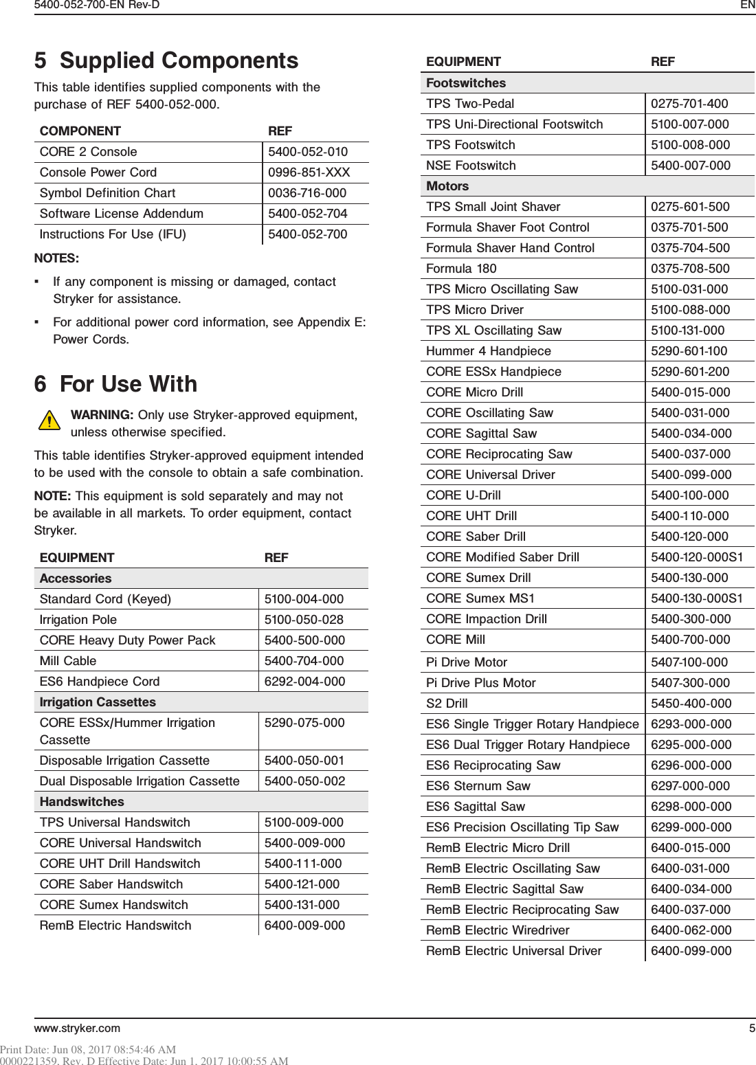
![12 www.stryker.comEN 5400-052-700-EN Rev-D11.4 Home Screen Instructions[Name 1]40000 RPM100 %90 %[Motor 1][Motor 2][Motor 3]B C D EAFigure 10 – Home ScreenA Navigation Bar Area – Provides navigational buttons and displays the active preset.NOTE: The reset button will appear within this area if the active preset has been modified. Press the reset button to undo changes.D Motor Settings Value Area – Displays the connected motor(s) name and value setting. Touch the motor value to access the slider bar to adjust the motor value setting.B Footswitch Assignment Area – Provides a graphical representation of the current footswitch assignment. These buttons can be touched to toggle footswitch assignment.E Decrease/Increase Area – From here, the user can use the decrease and increase buttons to adjust the motor value setting.C Quick Access Area – Allows the user to set features such as direction, irrigation, and mode on the Home screen. These buttons can be set to accommodate the user’s preference (Section 11.6.7.5).11.4.2 Access Other ScreensNOTE: The Home screen is where most user interaction will occur and allows access to other screens.From the Home screen: ▪ Touch (Preset) to access the preset screen. ▪ Touch (Settings) to access the system settings screen.11.4.1 Manage Connected DevicesNOTE: When navigating the software, touch (Home) to return to the Home screen.1. Access the Home screen.2. For each connected device, set the following as necessary (Figure 10): ▪ Motor settings value ▪ Footswitch assignment ▪ Quick access0000221359, Rev. D Effective Date: Jun 1, 2017 10:00:55 AMPrint Date: Jun 08, 2017 08:54:46 AM](https://usermanual.wiki/Stryker-Instruments/5400052020/User-Guide-3569287-Page-12.png)