Stryker Instruments 5400052020 13.56 MHz RFID Module User Manual
Stryker Instruments 13.56 MHz RFID Module Users Manual
Users Manual
2017-05 5400-052-700-EN Rev-D www.stryker.com
CORE™ 2 Console
5400-052-000
Instructions For Use
ENGLISH (EN) 1.X.X
Software Version
(01)07613327358247
0000221359, Rev. D Effective Date: Jun 1, 2017 10:00:55 AM
Print Date: Jun 08, 2017 08:54:46 AM

2 www.stryker.com
EN 5400-052-700-EN Rev-D
Contents
1 Introduction . . . . . . . . . . . . . . . . . . . . 3
1.1 Audience . . . . . . . . . . . . . . . . . . . 3
1.2 Conventions . . . . . . . . . . . . . . . . . . 3
1.3 Contact Information. . . . . . . . . . . . . . . 3
2 Indications For Use. . . . . . . . . . . . . . . . . 3
3 Contraindications . . . . . . . . . . . . . . . . . 3
4 Definitions . . . . . . . . . . . . . . . . . . . . . 3
5 Supplied Components . . . . . . . . . . . . . . . 5
6 For Use With . . . . . . . . . . . . . . . . . . . 5
7 Safety Directives . . . . . . . . . . . . . . . . . . 6
7.1 General Warnings . . . . . . . . . . . . . . . 6
7.2 Electrical Warnings . . . . . . . . . . . . . . . 6
8 System Overview. . . . . . . . . . . . . . . . . . 7
9 Hardware Features . . . . . . . . . . . . . . . . . 8
10 Screens and Menu Tabs . . . . . . . . . . . . . 9
11 Instructions . . . . . . . . . . . . . . . . . . . .10
11.1 Before the Procedure . . . . . . . . . . . . .10
11.2 During the Procedure . . . . . . . . . . . . .10
11.3 After the Procedure . . . . . . . . . . . . . .10
11.4 Home Screen Instructions . . . . . . . . . . . 12
11.4.1 Manage Connected Devices . . . . . . . .12
11.4.2 Access Other Screens. . . . . . . . . . .12
11.5 Preset Instructions. . . . . . . . . . . . . . .13
11.5.1 Create a Preset . . . . . . . . . . . . . .13
11.5.2 Edit a Preset . . . . . . . . . . . . . . . 13
11.5.3 Copy a Preset. . . . . . . . . . . . . . .13
11.5.4 Delete a Preset . . . . . . . . . . . . . .13
11.5.5 Save a Preset . . . . . . . . . . . . . . .13
11.5.6 Load a Preset . . . . . . . . . . . . . . .13
11.6 System Settings Instructions . . . . . . . . . .14
11.6.1 Manage Console Settings . . . . . . . . .14
11.6.2 Select a Motor and Edit Settings . . . . . .15
11.6.3 Manage Representative Information. . . . .15
11.6.3.1 Create New Rep Info. . . . . . . . . .15
11.6.3.2 Edit Rep Info . . . . . . . . . . . . .15
11.6.3.3 Delete Rep Info . . . . . . . . . . . .15
11.6.4 Set Control Permissions . . . . . . . . . .15
11.6.5 Import/Export Presets . . . . . . . . . . .16
11.6.6 Manage Irrigation . . . . . . . . . . . . .16
11.6.6.1 Prime the Irrigation Cassette . . . . . .16
11.6.6.2 Flush Irrigation Tubing . . . . . . . . .16
11.6.7 Manage Motor Settings . . . . . . . . . . 17
11.6.7.1 Adjust General (Motor Settings). . . . .17
11.6.7.2 Adjust Irrigation (Motor Settings) . . . . 17
11.6.7.3 Adjust Motor Options. . . . . . . . . .17
11.6.7.4 Adjust Control Options . . . . . . . . .17
11.6.7.5 Set Quick Access . . . . . . . . . . .18
12 Cleaning and Disinfection . . . . . . . . . . . . .19
12.1 Recommended Materials . . . . . . . . . . .19
12.2 Clean and Disinfect Procedure . . . . . . . . .19
13 Troubleshooting . . . . . . . . . . . . . . . . . .19
14 Maintenance . . . . . . . . . . . . . . . . . . .20
14.1 Fuse Replacement . . . . . . . . . . . . . .20
15 Storage and Handling . . . . . . . . . . . . . . .20
16 Disposal/Recycle . . . . . . . . . . . . . . . . .20
17 Appendices . . . . . . . . . . . . . . . . . . . .21
17.1 Appendix A: Acronyms . . . . . . . . . . . . .21
17.2 Appendix B: Audio Output . . . . . . . . . . .21
17.3 Appendix C: Colors . . . . . . . . . . . . . .21
17.3.1 User Interface Colors . . . . . . . . . . .21
17.3.2 Power Button Illumination Colors . . . . . .21
17.4 Appendix D: Equipotential Bonding . . . . . . .21
17.5 Appendix E: Power Cords . . . . . . . . . . .22
17.5.1 Power Cord General Specifications . . . . .22
17.5.2 Additional Power Cord Requirements . . . .22
17.6 Appendix F: Intellectual Property . . . . . . . .22
17.6.1 Software Licensing . . . . . . . . . . . .22
17.6.2 Trademarks . . . . . . . . . . . . . . . .22
17.7 Appendix G: Footswitch Pedal/Pad Options . . .23
17.7.1 Footswitch Pedal Direction Options . . . . .23
17.7.2 Footswitch Pedal Mode Options. . . . . . .23
17.7.3 Footswitch Pad Options . . . . . . . . . .23
17.8 Appendix H: Errors and Notifications . . . . . .24
17.9 Appendix I: Specifications . . . . . . . . . . .27
17.10 Appendix J: Electromagnetic Compatibility . . .29
17.11 Appendix K: Compliance Statements . . . . .31
0000221359, Rev. D Effective Date: Jun 1, 2017 10:00:55 AM
Print Date: Jun 08, 2017 08:54:46 AM
5400-052-700-EN Rev-D EN
www.stryker.com 3
1 Introduction
This manual contains information intended to ensure the
safe, effective, and compliant use of this product.
Keep and consult this manual as necessary.
1.1 Audience
This manual is intended for use by in-service trainers,
physicians, nurses, surgical assistants, and biomedical
equipment technicians.
1.2 Conventions
The following conventions are used in this manual:
▪ A WARNING highlights a safety-related issue. ALWAYS
comply with this information to prevent patient and/or
healthcare staff injury.
▪ A CAUTION highlights a product reliability issue.
ALWAYS comply with this information to prevent
product damage.
▪ A NOTE supplements and/or clarifies procedural
information.
1.3 Contact Information
For additional information, including safety information,
in-service training, or current literature, contact a Stryker
Sales Representative or call Stryker Customer Service at
1-269-323-7700 or 1-800-550-7836.
Outside the US, contact the nearest Stryker subsidiary.
2 Indications For Use
The Stryker Consolidated Operating Room Equipment
(CORE) 2 Console is intended for use in the cutting,
drilling, reaming, decorticating, shaping, and smoothing
of bone, bone cement and teeth in a variety of surgical
procedures, including but not limited to orthopedic, dental,
ENT (Ear, Nose, Throat), neuro, spine, and endoscopic
applications. The console is also usable in the placement
or cutting of screws, metal, wires, pins, and other fixation
devices.
3 Contraindications
None known.
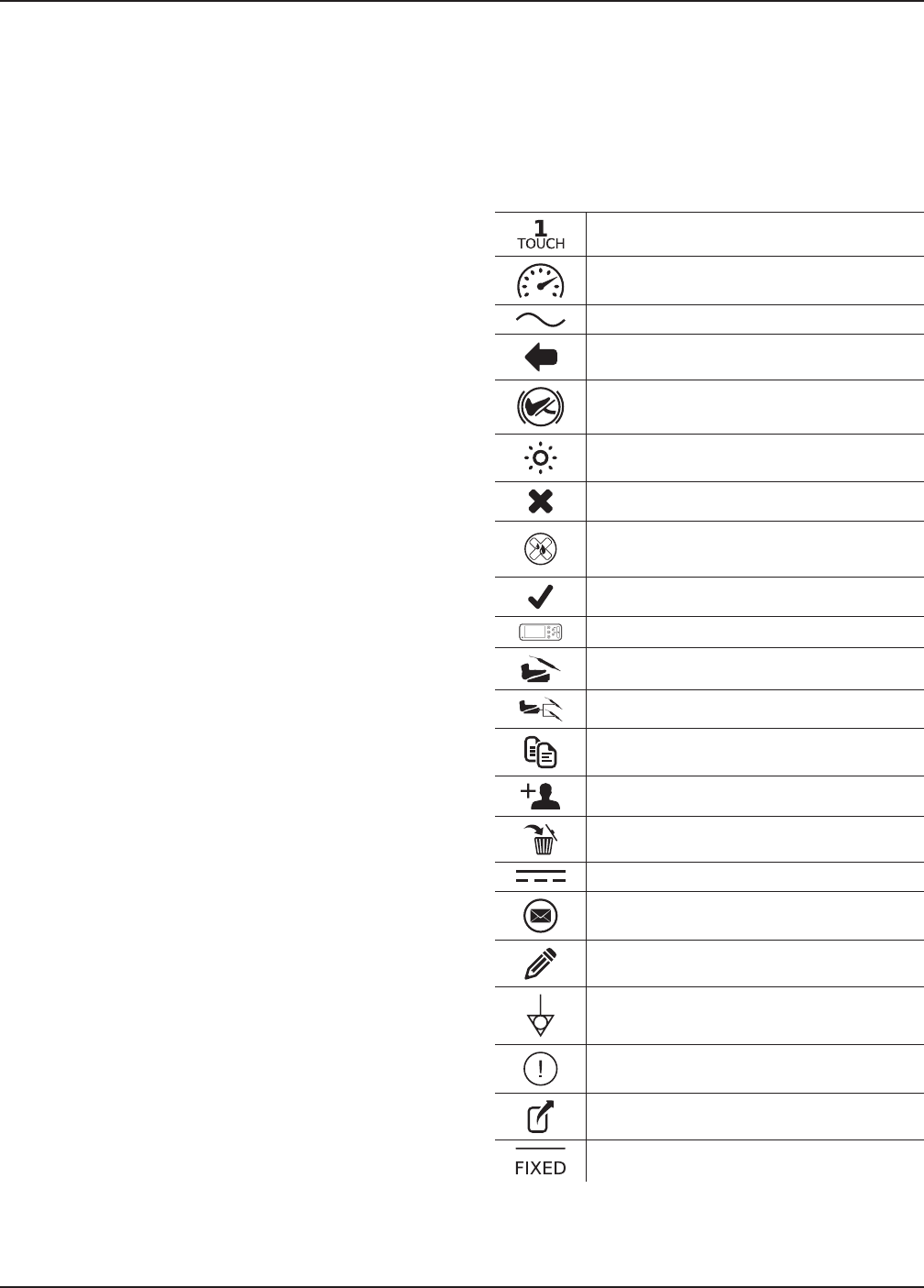
4 Definitions
The symbols located on the equipment and/or labeling
are defined in this section or in the Symbol Definition
Chart. Refer to the Symbol Definition Chart REF 0036-
716-000 supplied with the console.
SYMBOL DEFINITION
1Touch
Accelerate
Alternating Current
Back
Brake
Brightness
Cancel
Cancel Initial Prime
Confirm
Console
Control Options
Control Permissions
Copy
Create
Delete
Direct Current
Email
Edit
Equipotential
Error
Export
Fixed
0000221359, Rev. D Effective Date: Jun 1, 2017 10:00:55 AM
Print Date: Jun 08, 2017 08:54:46 AM
4 www.stryker.com
EN 5400-052-700-EN Rev-D
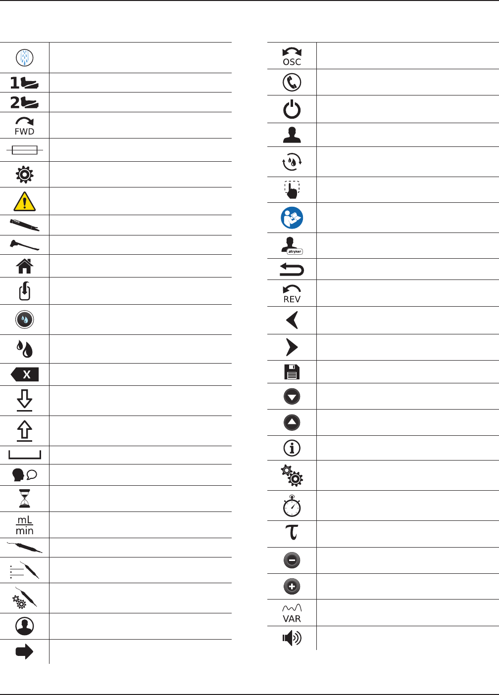
SYMBOL DEFINITION
Flush
Footswitch 1
Footswitch 2
Forward
Fuse
General Settings
General Warning Sign
Handpiece
Handswitch
Home
Import
Initial Prime
Irrigation
Keyboard - Backspace
Keyboard - Capital Letter OFF
Keyboard - Capital Letter ON
Keyboard - Spacebar
Language
Loading
Milliliters per Minute
Motor
Motor Options
Motor Settings
Name
Next
SYMBOL DEFINITION
Oscillating
Phone
Power
Preset/Representative
Priming
Quick Access
Refer to Instruction Manual/Booklet
Rep Info
Reset
Reverse
Roll-out Left
Roll-out Right
Save
Scroll Down
Scroll Up
System Information
System Settings
Time Based Turn
I.D. Touch (Torque)
Value - Decrease
Value - Increase
Variable
Volume
0000221359, Rev. D Effective Date: Jun 1, 2017 10:00:55 AM
Print Date: Jun 08, 2017 08:54:46 AM
5400-052-700-EN Rev-D EN
www.stryker.com 5
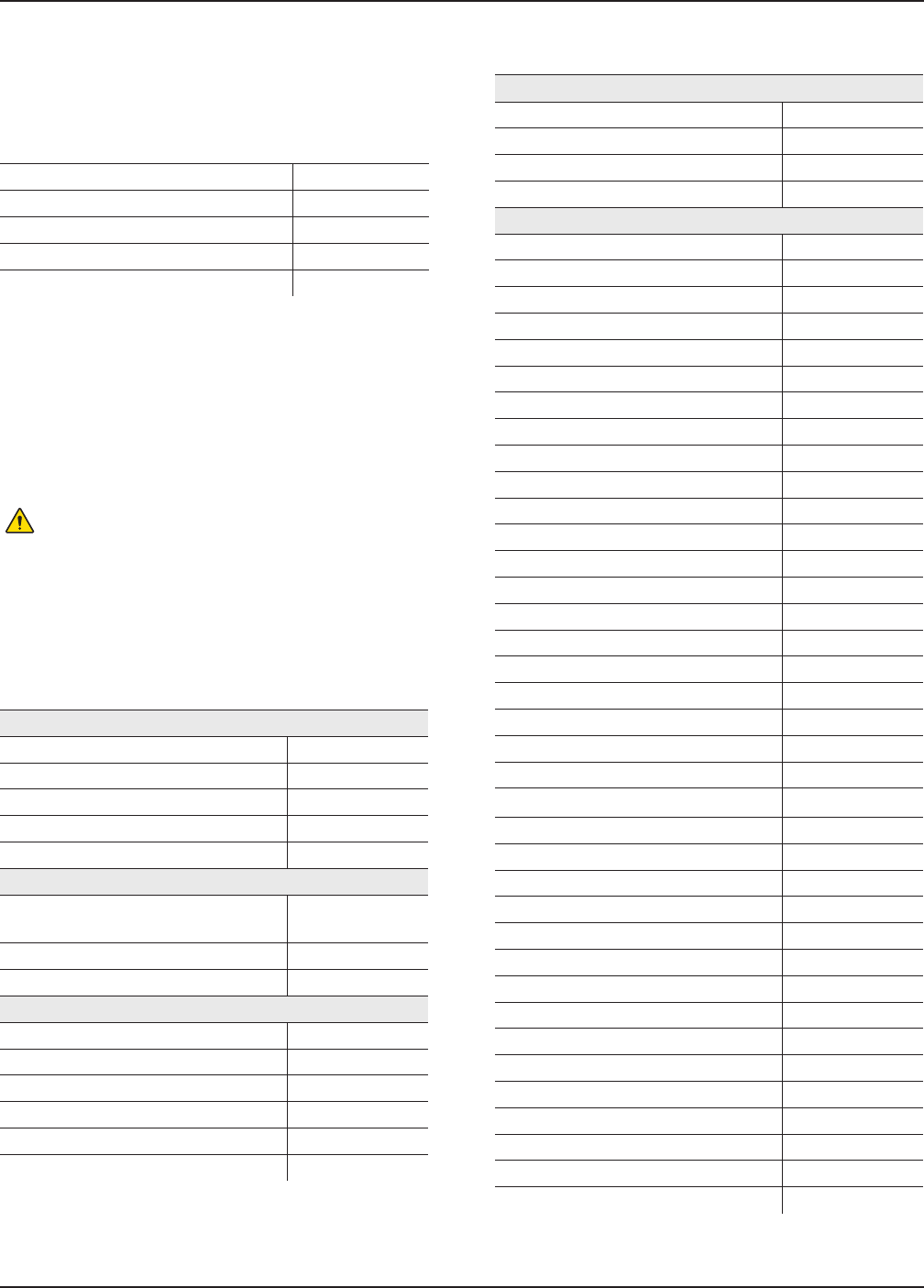
5 Supplied Components
This table identifies supplied components with the
purchase of REF 5400-052-000.
COMPONENT REF
CORE 2 Console 5400-052-010
Console Power Cord 0996-851-XXX
Symbol Definition Chart 0036-716-000
Software License Addendum 5400-052-704
Instructions For Use (IFU) 5400-052-700
NOTES:
▪ If any component is missing or damaged, contact
Stryker for assistance.
▪ For additional power cord information, see Appendix E:
Power Cords.
6 For Use With
WARNING: Only use Stryker-approved equipment,
unless otherwise specified.
This table identifies Stryker-approved equipment intended
to be used with the console to obtain a safe combination.
NOTE: This equipment is sold separately and may not
be available in all markets. To order equipment, contact
Stryker.
EQUIPMENT REF
Accessories
Standard Cord (Keyed) 5100-004-000
Irrigation Pole 5100-050-028
CORE Heavy Duty Power Pack 5400-500-000
Mill Cable 5400-704-000
ES6 Handpiece Cord 6292-004-000
Irrigation Cassettes
CORE ESSx/Hummer Irrigation
Cassette
5290-075-000
Disposable Irrigation Cassette 5400-050-001
Dual Disposable Irrigation Cassette 5400-050-002
Handswitches
TPS Universal Handswitch 5100-009-000
CORE Universal Handswitch 5400-009-000
CORE UHT Drill Handswitch 5400-111-000
CORE Saber Handswitch 5400-121-000
CORE Sumex Handswitch 5400-131-000
RemB Electric Handswitch 6400-009-000
EQUIPMENT REF
Footswitches
TPS Two-Pedal 0275-701-400
TPS Uni-Directional Footswitch 5100-007-000
TPS Footswitch 5100-008-000
NSE Footswitch 5400-007-000
Motors
TPS Small Joint Shaver 0275-601-500
Formula Shaver Foot Control 0375-701-500
Formula Shaver Hand Control 0375-704-500
Formula 180 0375-708-500
TPS Micro Oscillating Saw 5100-031-000
TPS Micro Driver 5100-088-000
TPS XL Oscillating Saw 5100-131-000
Hummer 4 Handpiece 5290-601-100
CORE ESSx Handpiece 5290-601-200
CORE Micro Drill 5400-015-000
CORE Oscillating Saw 5400-031-000
CORE Sagittal Saw 5400-034-000
CORE Reciprocating Saw 5400-037-000
CORE Universal Driver 5400-099-000
CORE U-Drill 5400-100-000
CORE UHT Drill 5400-110-000
CORE Saber Drill 5400-120-000
CORE Modified Saber Drill 5400-120-000S1
CORE Sumex Drill 5400-130-000
CORE Sumex MS1 5400-130-000S1
CORE Impaction Drill 5400-300-000
CORE Mill 5400-700-000
Pi Drive Motor 5407-100-000
Pi Drive Plus Motor 5407-300-000
S2 Drill 5450-400-000
ES6 Single Trigger Rotary Handpiece 6293-000-000
ES6 Dual Trigger Rotary Handpiece 6295-000-000
ES6 Reciprocating Saw 6296-000-000
ES6 Sternum Saw 6297-000-000
ES6 Sagittal Saw 6298-000-000
ES6 Precision Oscillating Tip Saw 6299-000-000
RemB Electric Micro Drill 6400-015-000
RemB Electric Oscillating Saw 6400-031-000
RemB Electric Sagittal Saw 6400-034-000
RemB Electric Reciprocating Saw 6400-037-000
RemB Electric Wiredriver 6400-062-000
RemB Electric Universal Driver 6400-099-000
0000221359, Rev. D Effective Date: Jun 1, 2017 10:00:55 AM
Print Date: Jun 08, 2017 08:54:46 AM

6 www.stryker.com
EN 5400-052-700-EN Rev-D
7 Safety Directives
7.1 General Warnings
WARNINGS:
▪ ALWAYS be familiar with the Instructions For Use and
proper operation of this equipment before use. To
request in-service training, contact Stryker.
▪ ALWAYS consult the Instructions For Use that
accompanies motors, footswitches, and attachments
for product specific duty cycles and additional
information.
▪ Only healthcare professionals trained and experienced
in the use of this medical device should operate this
equipment.
▪ Healthcare professionals should be thoroughly familiar
with the Instructions For Use, handling characteristics,
and the indicated and intended uses of this equipment.
Contact Stryker for in-service training.
▪ The healthcare professional performing any procedure
is responsible for determining the appropriateness of
this equipment and the specific technique used for
each patient. Stryker, as a manufacturer, DOES NOT
recommend surgical procedure or technique.
▪ ALWAYS ensure the console is placed on a sturdy,
flat surface near a hospital-grade power outlet and all
connections (front and rear) are easily accessible.
▪ Upon initial receipt and before each use, ALWAYS
inspect equipment for damage. DO NOT use any
equipment if damage is apparent.
▪ ALWAYS clean and disinfect the equipment as
indicated upon initial receipt and before each use.
Failure to comply may cause infection and result in
patient and/or healthcare staff injury.
▪ ALWAYS consult the Instructions For Use that
accompanies motors, footswitches, and attachments
for product specific cleaning requirements.
▪ DO NOT touch the screen with any sharp or hard
object. Failure to comply may cause breakage and
result in healthcare staff and/or patient injury.
▪ DO NOT disassemble, modify, service, or repair this
equipment when using this equipment with a patient.
▪ DO NOT disassemble, modify, service, or repair
any equipment without the authorization of the
manufacturer. For assistance, contact Stryker.
▪ ALWAYS operate this equipment within the specified
environmental condition values (Appendix I:
Specifications).
▪ ALWAYS follow the recommended duty cycle to prevent
this equipment from overheating.
▪ DO NOT stack or place equipment adjacent to the
console. If such a configuration is necessary, observe
the configuration to ensure that electromagnetic
interference does not degrade performance.
▪ Take special precautions regarding electromagnetic
compatibility (EMC) when using medical electrical
equipment like the console. Portable and mobile radio
frequency (RF) communications equipment can affect
the function of the console.
▪ DO NOT use the console in an MRI environment.
Using the console in an MRI environment could affect
the function of the console.
▪ ALWAYS ensure footswitch placement is in a secure
area where inadvertent activation is not possible.
▪ ALWAYS select the correct irrigation flow rate based on
the surgical procedure and/or handpiece requirements
to prevent excessive or insufficient irrigation flow.
Failure to comply may limit the view of the surgical site
and result in patient and/or healthcare staff injury.
▪ ALWAYS select the correct attachment/reducer when
selecting the motor setting to prevent excessive or
insufficient motor speed. Failure to comply may cause
incorrect information to be displayed and result in
patient and/or healthcare staff injury.
▪ DO NOT place the console within the sterile field.
7.2 Electrical Warnings
WARNINGS:
▪ ALWAYS connect the console to a hospital-grade,
power outlet with protective earth (ground) to avoid the
risk of electrical shock.
▪ Electrical power is present when the console is
in standby mode. To completely remove power,
disconnect the power cord from either the console or
the hospital-grade, power outlet with protective earth
(ground) to avoid the risk of electrical shock.
▪ If power is lost, some of the console’s adjustable
settings, such as the motor to footswitch assignment,
footswitch options, and motor operating modes, will
revert to the default configuration or the last selected
preset. After power is restored, verify console settings.
0000221359, Rev. D Effective Date: Jun 1, 2017 10:00:55 AM
Print Date: Jun 08, 2017 08:54:46 AM
5400-052-700-EN Rev-D EN
www.stryker.com 7
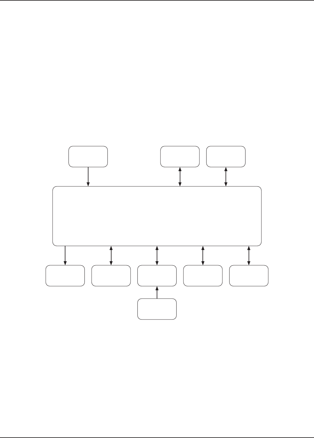
8 System Overview
The CORE 2 Console has three handpiece ports, two
footswitch ports, and one irrigation cassette port. The
console supplies power to a variety of devices including
small and large bone drills, small and large bone saws,
small and large bone drivers, large joint and small
joint shavers, ENT shavers, bone mills, and various
footswitches. Additionally, the console supports the use
of irrigation. For a complete list of equipment that can
be used with the console, see Section 6.
When a device is connected to the console, the console
automatically detects the connected device and will
only display options and settings that are available for
the connected device.
The touch screen provides visual output and serves as
an input device when navigating the user interface. The
internal speaker provides audio output during operation.
See Appendix B: Audio Output for additional information.
The console can store user presets and representative
information internally. The presets can be exported from
one console and imported to another console with the
use of a USB data storage device (Section 11.6.5).
Handswitches
Console
100-240 VAC
50-60 Hz
Irrigation
Cassette
Footswitches
Motors/
Handpieces
EthernetUSB
Audio Output
Touch
Screen
Figure 1 – System Block Diagram
0000221359, Rev. D Effective Date: Jun 1, 2017 10:00:55 AM
Print Date: Jun 08, 2017 08:54:46 AM
8 www.stryker.com
EN 5400-052-700-EN Rev-D
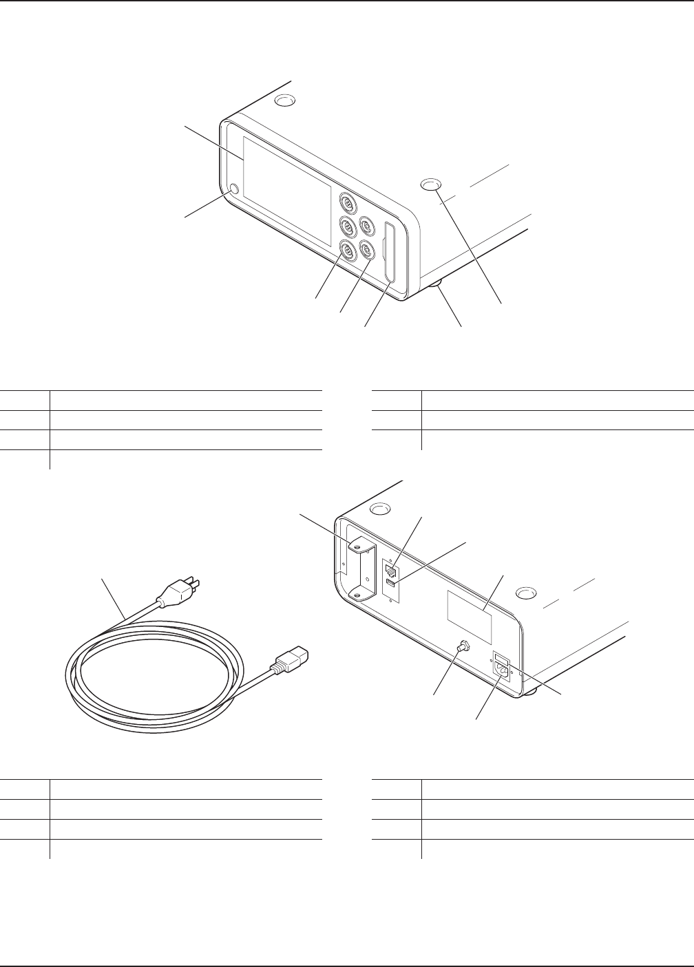
9 Hardware Features
B
A
G
F
E D
C
Figure 2 – Console (Front View)
APower Button EIrrigation Cassette Port
BTouch Screen FFootswitch Ports (2)
CStacking Inserts (4) GMotor Ports (3)
DStacking Feet (4)
H
I
K
N
O
J
L
M
Figure 3 – Console (Rear View)
HPower Cord LSpecification Label
IPole Bracket MFuse Holder
JEthernet Port NPower Receptacle
KUSB Port OEquipotential Lug
0000221359, Rev. D Effective Date: Jun 1, 2017 10:00:55 AM
Print Date: Jun 08, 2017 08:54:46 AM
5400-052-700-EN Rev-D EN
www.stryker.com 9
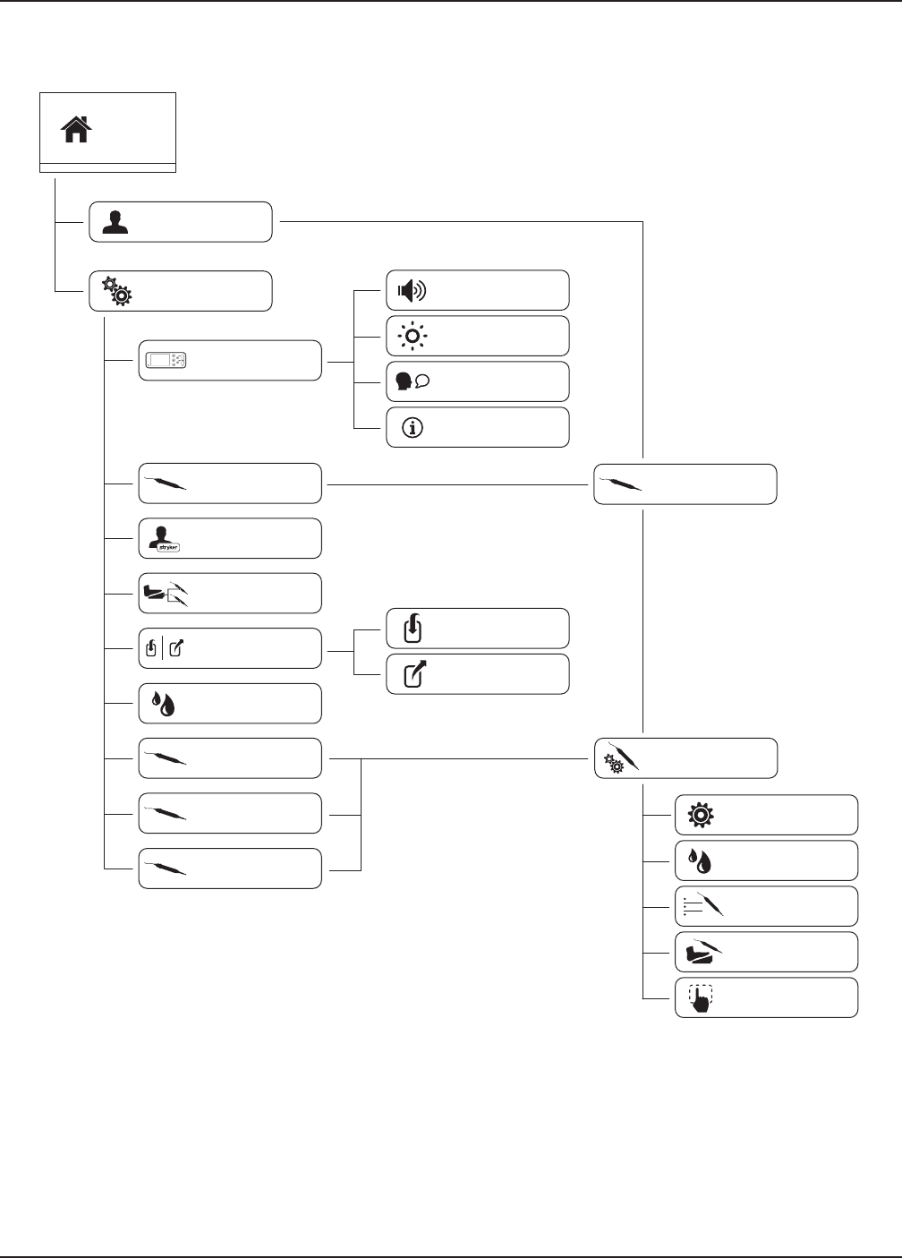
10 Screens and Menu Tabs
Preset
Console
System Settings
Select Motor
Rep Info
Control
Permissions
Import/Export
Irrigation
Motor 1
Motor 2
Motor 3
Home
Import
Volume
Brightness
Language
System Info
Export
Motor List
Motor Settings
General
Irrigation
Motor Options
Control Options
Quick Access
Figure 4 – Screens and Menu Tabs Map
0000221359, Rev. D Effective Date: Jun 1, 2017 10:00:55 AM
Print Date: Jun 08, 2017 08:54:46 AM
10 www.stryker.com
EN 5400-052-700-EN Rev-D
11 Instructions
WARNING: Before using this equipment, or any
compatible equipment, read and understand the
Instructions For Use. Pay particular attention to
safety information. ALWAYS become familiar with
the equipment before use.
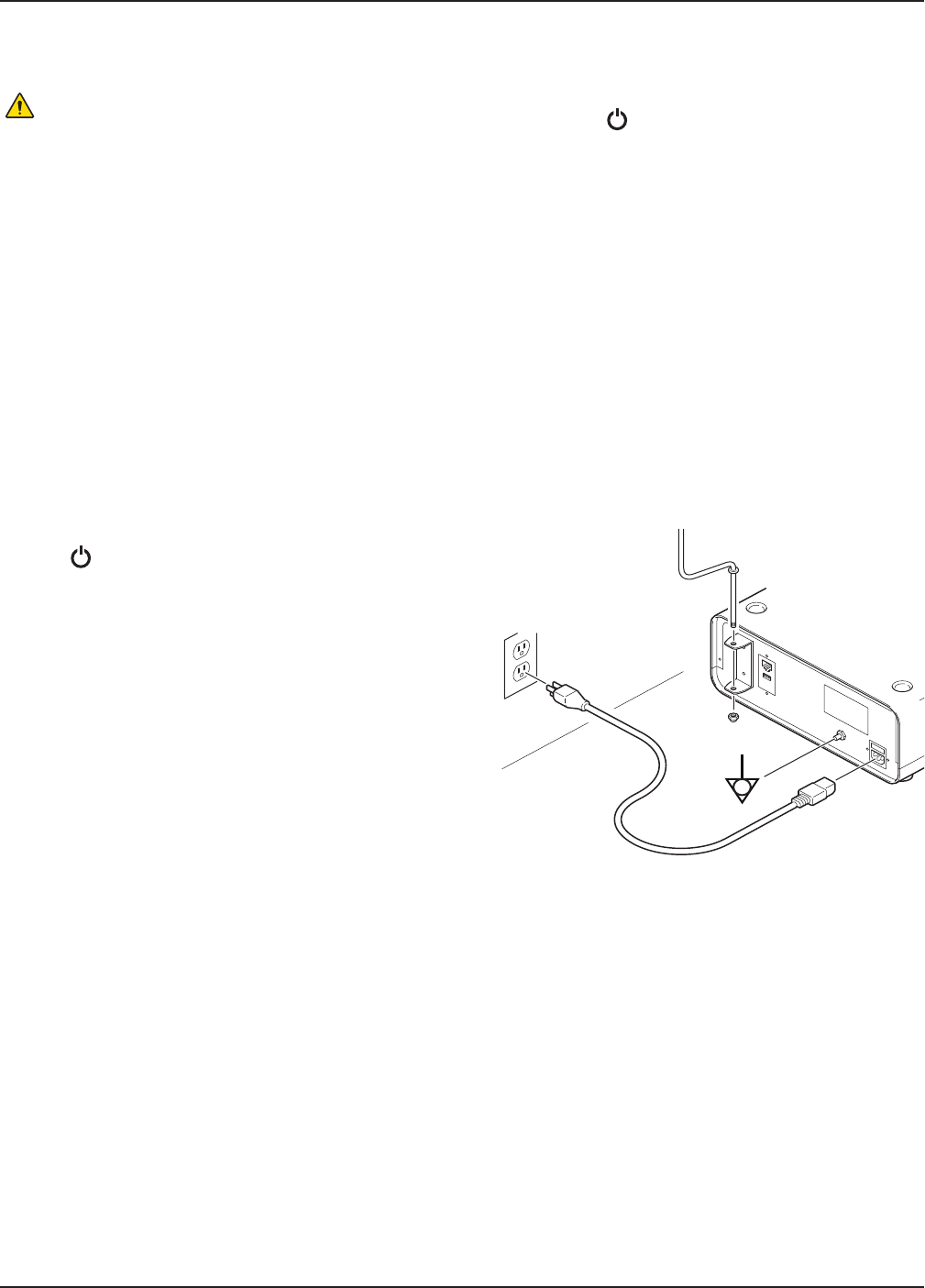
11.1 Before the Procedure
1. Verify the console is placed on a sturdy, flat surface.
2. Verify the console is not within the sterile field.
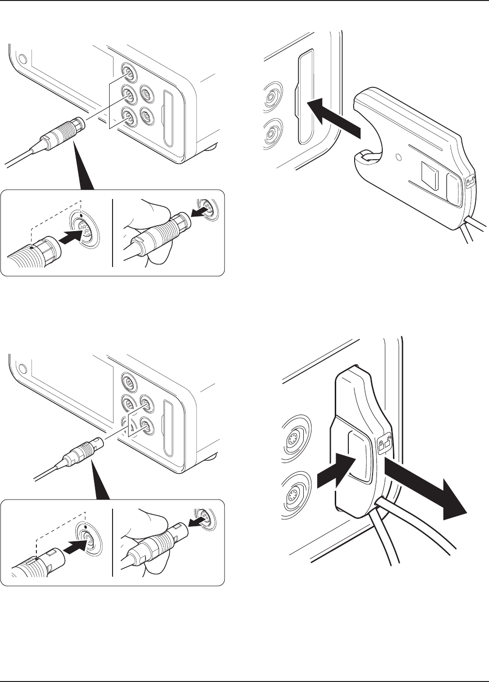
3. Verify the following items are connected; connect as
necessary (Figure 5):
▪ (Optional) Equipotential cable
▪ Power cord
4. Verify the equipment is clean and not damaged.
5. Connect the following devices as necessary:
▪ Motor(s) (Figure 6)
▪ Footswitch(es) (Figure 7)
6. Press to power the console on.
7. (Optional) Prepare the console for irrigation as follows:
7. 1. If required, install an irrigation pole into the pole
bracket on the rear of the console (Figure 5).
7. 2. Insert an irrigation cassette (Figure 8).
7. 3. Attach the irrigation clips onto the motor and
connect the tubing to the irrigation bag.
7. 4. Prime the irrigation cassette (Section 11.6.6.1).
8. Manage presets as necessary (Section 11.5).
9. Manage system settings as necessary (Section 11.6).
11.2 During the Procedure
▪ Connect and disconnect devices as necessary.
▪ If using irrigation, flush irrigation tubing as necessary
(Section 11.6.6.2).
▪ Refer to the following sections for guidance during the
procedure as necessary:
▪ Section 11.4 Home Screen Instructions
▪ Section 11.5 Preset Instructions
▪ Section 11.6 System Settings Instructions
11.3 After the Procedure
1. Remove power from the console as follows:
1. 1. Press to set the console in standby mode.
CAUTION: Some power cords have a locking mechanism,
press the colored tab prior to disconnection.
1. 2. Disconnect the power cord.
1. 3. If used, disconnect the equipotential cable.
2. If irrigation was used, perform the following:
2. 1. Detach the irrigation clips from the motor and
disconnect the tubing from the irrigation bag.
2. 2. Remove the irrigation cassette (Figure 9).
3. Disconnect the following devices as necessary:
▪ Motor(s) (Figure 6)
▪ Footswitch(es) (Figure 7)
4. Clean and disinfect the console (Section 12).
5. Inspect the equipment for damage.
Figure 5 – Console (Rear View)
0000221359, Rev. D Effective Date: Jun 1, 2017 10:00:55 AM
Print Date: Jun 08, 2017 08:54:46 AM
5400-052-700-EN Rev-D EN
www.stryker.com 11
Figure 6 – To Connect/Disconnect a Motor
Figure 7 – To Connect/Disconnect a Footswitch
Figure 8 – To Insert an Irrigation Cassette
Figure 9 – To Remove an Irrigation Cassette
0000221359, Rev. D Effective Date: Jun 1, 2017 10:00:55 AM
Print Date: Jun 08, 2017 08:54:46 AM
12 www.stryker.com
EN 5400-052-700-EN Rev-D
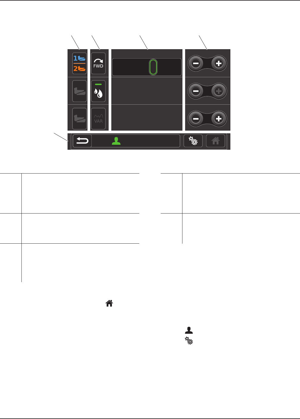
11.4 Home Screen Instructions
[Name 1]
40000 RPM
100 %
90 %
[Motor 1]
[Motor 2]
[Motor 3]
B C D E
A
Figure 10 – Home Screen
A Navigation Bar Area – Provides navigational
buttons and displays the active preset.
NOTE: The reset button will appear within this
area if the active preset has been modified.
Press the reset button to undo changes.
D Motor Settings Value Area – Displays the
connected motor(s) name and value setting.
Touch the motor value to access the slider bar
to adjust the motor value setting.
B Footswitch Assignment Area – Provides
a graphical representation of the current
footswitch assignment. These buttons can be
touched to toggle footswitch assignment.
E Decrease/Increase Area – From here, the user
can use the decrease and increase buttons to
adjust the motor value setting.
C Quick Access Area – Allows the user to set
features such as direction, irrigation, and mode
on the Home screen. These buttons can be
set to accommodate the user’s preference
(Section 11.6.7.5).
11.4.2 Access Other Screens
NOTE: The Home screen is where most user interaction
will occur and allows access to other screens.
From the Home screen:
▪ Touch (Preset) to access the preset screen.
▪ Touch (Settings) to access the system settings
screen.
11.4.1 Manage Connected Devices
NOTE: When navigating the software, touch (Home)
to return to the Home screen.
1. Access the Home screen.
2. For each connected device, set the following as
necessary (Figure 10):
▪ Motor settings value
▪ Footswitch assignment
▪ Quick access
0000221359, Rev. D Effective Date: Jun 1, 2017 10:00:55 AM
Print Date: Jun 08, 2017 08:54:46 AM