Stryker Medical 6390 Power-LOAD User Manual 10f4
Stryker Medical Power-LOAD Users Manual 10f4
Contents
- 1. Users Manual 10f4
- 2. Users Manual 20f4
- 3. Users Manual 30f4
- 4. Users Manual 40f4
Users Manual 10f4

2011/10 B.4 6390-009-001 REV B www.stryker.com
Power-LOAD™
Cot Fastener System
Model 6390
Operations/Maintenance Manual
For parts or technical assistance:
USA: 1-800-327-0770

www.stryker.com 6390-009-001 REV B 3
Table of Contents
Symbols and Definitions ....................................................................5
Symbols ............................................................................5
Warning/Caution/Note Definition ...........................................................6
Introduction .............................................................................7
Product Description ....................................................................7
Intended Use of Product.................................................................7
Product Illustration.....................................................................7
Important Contact Information ............................................................8
Stryker Contact Information ..............................................................8
Serial Number Location .................................................................8
Specifications ........................................................................9
Summary of Safety Precautions .............................................................11
Pinch Points ........................................................................13
Vehicle Cot Compatibility Information .........................................................14
Installation Setup Procedures ...............................................................15
Floor Plate Assembly Installation Component Checklist .........................................15
Power-LOAD Assembly Installation Component Checklist .......................................16
Optional Wheel Guide Assembly Installation Component Checklist ................................17
Quality System Regulation for Installation ......................................................18
Quality System Regulation ..............................................................18
Floor Plate Installation Guidelines ............................................................19
Installation Guide ........................................................................21
Installing the Floor Plate (with a Wood Floor) ................................................21
Installing the Power-LOAD System ........................................................27
Installing The Optional Wheel Guide.......................................................34
Installing Cot Wheel Covers .............................................................37
Power-LOAD Installation Checklist ........................................................38
User Setup Procedures....................................................................40
User Controls and LED Indicators ............................................................41
Manual User Controls.....................................................................43
Power-PRO Cot User Controls...............................................................44
Using the Cot Control Switches ..........................................................44
Checking the Cot Battery Power Level .....................................................45
Powered Operations Instructions.............................................................46
Manual Operations Instructions..............................................................47
Operation Guide.........................................................................48
Operating Guidelines ..................................................................48
Checking the Battery Power Level ........................................................49
Charging the Battery ..................................................................49
Storing Power-LOAD ..................................................................49
Setting the Cot Load Height .............................................................49
Using a Non-Upgraded X-Frame Cot for a Mass Casualty Incident ................................50
Extending Power-LOAD from the Vehicle without a Cot .........................................50
Loading a Performance-PRO Cot into a Vehicle (Model 6085/6086 with the Power-LOAD Option) .........51
Unloading a Performance-PRO Cot from a Vehicle (Model 6085/6086 with the Power-LOAD Option) .......53

4 6390-009-001 REV B www.stryker.com
Loading a Power-PRO Cot into a Vehicle (Model 6500/6506 & 6510/6516 with the Power-LOAD Option).....55
Unloading a Power-PRO Cot from a Vehicle (Model 6500/6506 & 6510/6516 with the Power-LOAD Option) ..57
Unloading a Cot From a Vehicle Manually (Power-LOAD Power Loss or System Error) ..................59
Loading a Cot into a Vehicle Manually (Power-LOAD Power Loss or System Error) ....................61
Unloading a Cot from a Vehicle Manually ...................................................62
Removing a Cot from a Vehicle for Repair ..................................................63
Loading a Cot into a Vehicle Manually (Power-PRO Power Loss) ..................................64
Cleaning...............................................................................66
Cleaning Procedure ...................................................................66
Cleaning Limitations...................................................................66
Removal of Iodine Compounds ...........................................................67
Preventative Maintenance..................................................................68
Warranty ..............................................................................69
Stryker EMS Return Policy ..............................................................70
Return Authorization...................................................................70
Damaged Merchandise ................................................................70
International Warranty Clause............................................................70
Patent Information ....................................................................70
EMC Information.........................................................................71
Table of Contents
www.stryker.com 6390-009-001 REV B 5
Return To Table of Contents
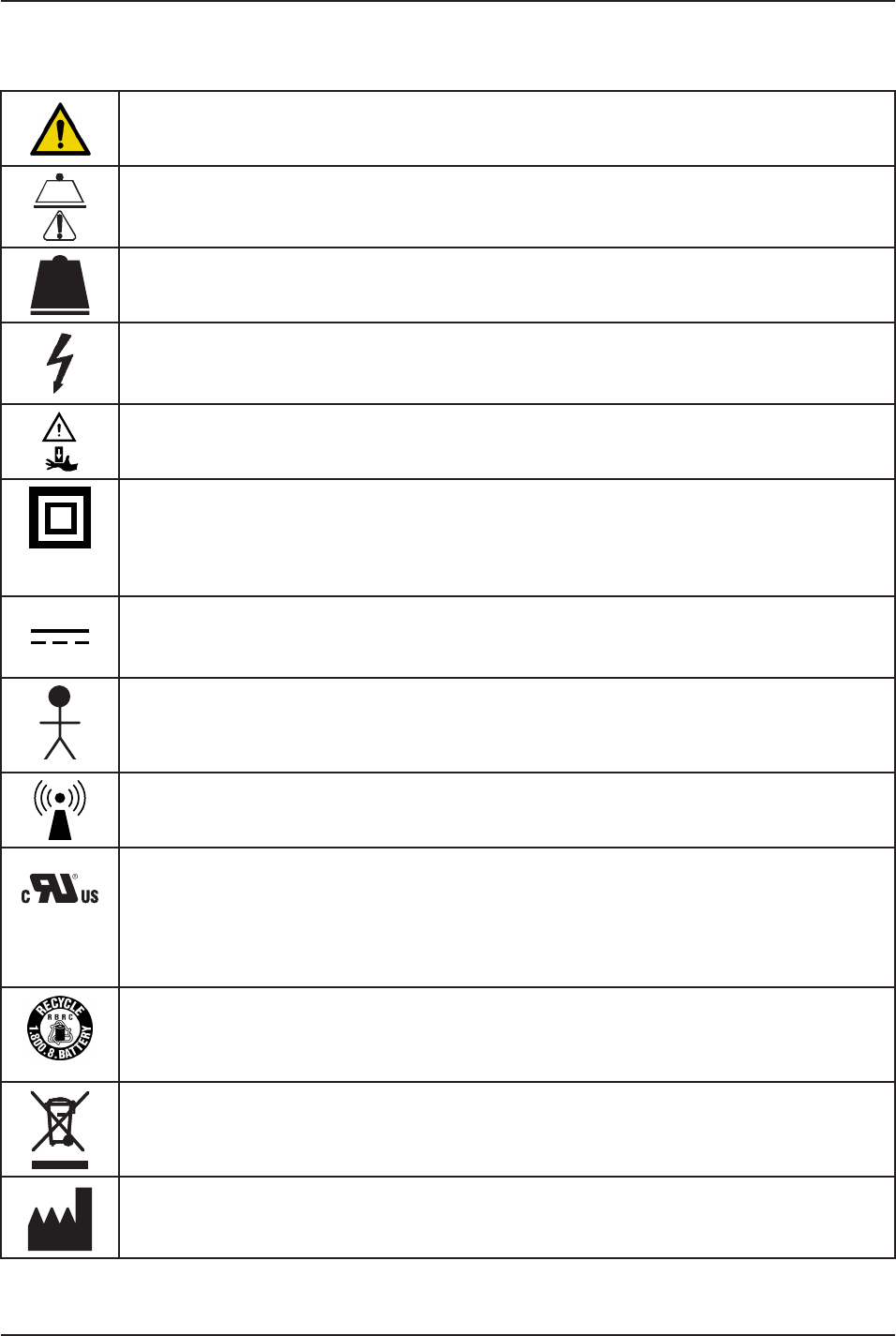
Symbols and Definitions
Warning, consult accompanying documentation
Safe Working Load
Maximum Weight
Dangerous Voltage
Pinch Point
Class II Equipment: equipment in which protection against electric shock does not rely on basic
insulation only, but in which additional safety precautions such as double insulation or reinforced
insulation are provided, there being no provision for protective earthing or reliance upon installation
conditions.
Direct Current
Type B Equipment: equipment providing a particular degree of protection against electric shock,
particularly regarding allowable leakage current and reliability of the protective earth connection.
Internally Powered.
ME EQUIPMENT or ME EQUIPMENT parts that include RF transmitters or that apply RF electromagnetic
energy for diagnosis or treatment
UL60601-1
CAN/CSA
C22.2 NO.
601.1
Medical Equipment Recognized by Underwriters Laboratories Inc. With Respect to Electric Shock,
Fire, and Mechanical Hazards Only in Accordance with UL 60601−1, and CAN/CSA C22.2 No. 601.1.
The Rechargeable Battery Recycling Corporation (RBRC) is a non-profit, public service organization
that promotes the recycling of portable rechargeable batteries. Batteries must be delivered to a
battery collection site. Visit the RBRC website (www.rbrc.org) to find a nearby collection site or call
the phone number shown on the recycling symbol.
In accordance with European Directive 2002/96/EC on Waste Electrical and Electronic Equipment,
this symbol indicates that the product must not be disposed of as unsorted municipal waste, but
should be collected separately. Refer to your local distributor for return and/or collection systems
available in your country.
Manufacturer
SYMBOLS

6 6390-009-001 REV B www.stryker.com
Return To Table of Contents
Symbols and Definitions
WARNING/CAUTION/NOTE DEFINITION
The words WARNING, CAUTION and Note carry special meanings and should be carefully reviewed.
WARNING
Alerts the reader about a situation which, if not avoided, could result in death or serious injury. It may also describe
potential serious adverse reactions and safety hazards.
CAUTION
Alerts the reader of a potentially hazardous situation which, if not avoided, may result in minor or moderate injury to the
user or patient or damage to the equipment or other property. This includes special care necessary for the safe and
effective use of the device and the care necessary to avoid damage to a device that may occur as a result of use or
misuse.
Note
Provides special information to make maintenance easier or important instructions clearer.
www.stryker.com 6390-009-001 REV B 7
Return To Table of Contents
Introduction
This manual is designed to provide instructions for the operation and maintenance of the Stryker 6390 Power-LOAD™.
Read it thoroughly before installing or using the equipment or beginning any maintenance on it.
PRODUCT DESCRIPTION
The Stryker 6390 Power-LOAD is designed to assist the user in loading the cot into a vehicle, unloading the cot from
the vehicle, and to restrict the movement of the cot as it is being transported in the vehicle patient compartment under
normal conditions. Usage of this product in any other way becomes the complete responsibility of the owner/user.
Caution must be used at all times during placement of the cot into the vehicle patient compartment.
INTENDED USE OF PRODUCT
The Stryker 6390 Power-LOAD is intended to aid in the loading and unloading of a cot, patient and corresponding
equipment to and from an ambulance/transport vehicle and holding of the cot during the transport (transports include
from an emergency scene or patient location to a medical care center, from a medical care center to a medical care
center, from a nursing home to another facility, etc). The safe working load of the system is 870 lb (395 kg), with a
maximum patient weight of 700 lb (318 kg). Users of the device will be emergency medical service and medical care
center personnel, as well as medical first responders, service technicians and installers. The device has an expected
life of 7 years.
PRODUCT ILLUSTRATION
Trolley Assembly
Transfer Assembly
Anchor Assembly
Floor
Plate
Head End Lock LED
Error LED
Battery LED
FOOT END
HEAD END
Figure 1: Product Illustration
Safety Hook
8 6390-009-001 REV B www.stryker.com
Return To Table of Contents
Introduction
IMPORTANT CONTACT INFORMATION
For information about Federal Ambulance Specification KKK−A−1822, contact:
Chief, Automotive & Commodity Management Branch (QMDAA)
Office of Motor Vehicle Management
General Services Administration
2200 Crystal Drive, Suite 1006
Arlington, VA 22202
Telephone: 703-605-2277
For more information about AMD standards, contact:
Ambulance Manufacturers Division
(National Truck Equipment Association)
37400 Hills Tech Drive
Farmington Hills, MI 48331−3414
STRYKER CONTACT INFORMATION
Contact Stryker Customer Service or Technical Support at (800) 327-0770.
Stryker Medical
3800 E. Centre Avenue
Portage, MI 49002
USA
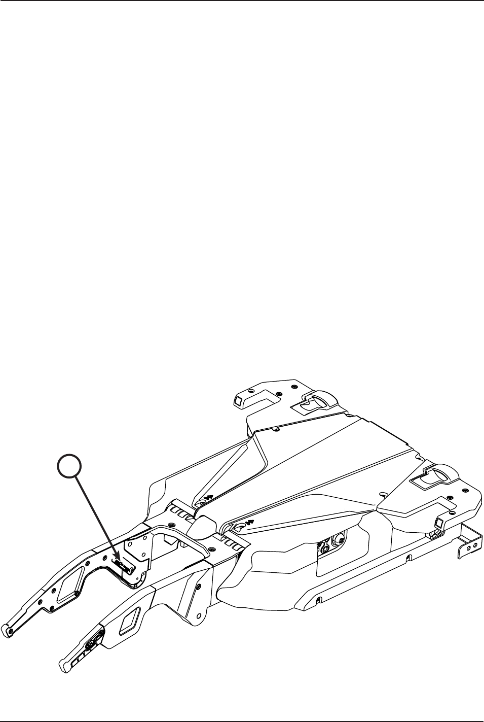
Please have the serial number (A) of your Stryker product available when calling Stryker Customer Service or Technical
Support. Include the serial number in all written communication.
SERIAL NUMBER LOCATION
A
Figure 2: Serial Number Location
www.stryker.com 6390-009-001 REV B 9
Return To Table of Contents
Introduction
SPECIFICATIONS
Safe Working Load
Note: Safe Working Load represents the sum of
the cot total weight and patient
870 lb 395 kg
Maximum Lift Capacity (patient and accessories) 700 lb 318 kg
Overall Length/Minimum Length/Width 95 in / 85 in / 24.5 in 241 cm / 216 cm / 62 cm
Weight
Floor Plate Assembly 16.5 lb 7.5 kg
Anchor Assembly 23 lb 10.5 kg
Transfer Assembly 67 lb 30.5 kg
Trolley Assembly 105 lb 48 kg
Minimum Operators Required for Loading/
Unloading an Occupied Cot
2
Minimum Operators Required for Loading/
Unloading an Unoccupied Cot
1
Recommended Loading Height 22 in to 36 in 56 cm to 91 cm
Hydraulic Oil Mobil Mercon® V Synthetic Blend Oil (6500-001-293)
Electrical Requirements 12.8V-15.6V , 15A breaker, 2 conductor 10 AWG cable
Battery Duty Cycle, Charging 100%
Battery Duty Cycle, Loading 10% (33 sec On / 5 min Off)
Battery 12V , 5 Ah Lead Acid Battery (6390-001-468)
Standards IEC 60601-1 CAN/CSA-C22.2 No. 601.1-M90
UL 60601-1 IEC 60601-1-2:2007
Stryker reserves the right to change specifications without notice.
Patents pending.
The yellow and black color scheme is a proprietary trademark of Stryker Corporation.
WARNING
• Do not operate Power-LOAD using a voltage inconsistent with the rating on the unit.
• To avoid the risk of equipment damage or smoke hazard, do not use Power-LOAD above its duty cycle.
• To ensure performance and prevent power hazards, connect Power-LOAD to a 12.8V-15.6V DC vehicle circuit that is
on a 15A breaker. Do not connect Power-LOAD to a 24V DC vehicle circuit.
CAUTION
• Changes or modifications to the Power-LOAD system not expressly approved by Stryker could void the user’s
authority to operate the system.
• This equipment has been tested and found to comply with the limits for a Class A digital device, pursuant to part
15 of the FCC Rules. These limits are designed to provide reasonable protection against harmful interference when
the equipment is operated in a commercial environment. This equipment generates, uses, and can radiate radio
frequency energy and, if not installed and used in accordance with the instruction manual, may cause harmful
interference to radio communications. Operation of this equipment in a residential area is likely to cause harmful
interference in which case the user will be required to correct the interference at their expense.


www.stryker.com 6390-009-001 REV B 11
Return To Table of Contents
Summary of Safety Precautions
Carefully read and strictly follow the warnings and cautions listed on this page. Service only by qualified personnel.
WARNING
• Do not operate Power-LOAD using a voltage inconsistent with the rating on the unit.
• To avoid the risk of equipment damage or smoke hazard, do not use Power-LOAD above its duty cycle.
• To ensure performance and prevent power hazards, connect Power-LOAD to a 12.8V-15.6V DC vehicle circuit that
is on a 15A breaker. Do not connect Power-LOAD to a 24V DC vehicle circuit.
• Power-LOAD is designed to be compatible with the Performance-PRO XT, Power-PRO XT, and Power-PRO IT cots
with the Power-LOAD option only. In certain situations, you can use Power-LOAD as a standard antler for most
X-frame cots, but a rail clamp assembly is required for all cots without the Power-LOAD option.
• It is the responsibility of the cot operator to ensure that the cot being used in the Stryker Model 6390 Power-LOAD
system is a Power-LOAD compatible cot. Injury may result if a non-compatible cot is used in the Stryker Model
6390 Power-LOAD system.
• Improper installation can result in injury. Install the Stryker Model 6390 Power-LOAD system as described in this
manual. Ensure that, at a minimum, your configuration with Power-LOAD is tested to meet AMD Standard 004.
• Take special precautions regarding electromagnetic compatibility (EMC) when using medical electrical equipment
like Power-LOAD. Install and place Power-LOAD into service according to the EMC information in this manual.
Portable and mobile RF communications equipment can affect the function of Power-LOAD.
• To avoid the risk of personal injury or equipment damage, properly secure the item that you are cutting and be
aware of the area around your cutting location. Always wear appropriate eye protection while operating a saw.
• During installation, always wear safety glasses and a face mask while operating a router.
• To avoid the risk of personal injury or vehicle damage, be aware of items around and below the electrical inlet during
floor plate installation.
• Ensure that all gaps to the exterior of the vehicle are sealed to prevent exhaust fumes from entering the vehicle
patient compartment.
• To prevent exhaust fumes from entering the vehicle patient compartment, route the drain tube under the vehicle
away from the exhaust system.
• To avoid the risk of personal injury or vehicle damage, be aware of items around and below the anchor to vehicle
cable during floor plate installation.
• Failure to install the safety hook can cause injury to the patient or operator. Install and use the safety hook as
described in this manual.
• To avoid the risk of injury, two installers are required when lifting and positioning the transfer assembly.
• To avoid the risk of injury, keep hands and fingers clear of all moving mechanisms.
• To avoid the risk of injury, two installers are required when lifting and positioning the trolley assembly.
• To avoid the risk of patient injury, adjust the cot height to match the vehicle deck height as described in the
appropriate cot operations/maintenance manual for your cot model.
• Improper usage of the Power-LOAD system or any accessory can cause injury to the patient or operator. Operate
the Power-LOAD system and accessories only as described in the manuals.
• For manual operations, the operator must support the foot end of the cot.
• Failure to ensure proper Power-LOAD functionality prior to use may result in patient and/or operator injury.
• Use caution while moving around in the vehicle patient compartment to avoid tripping on Power-LOAD.
• To avoid the risk of operator and/or patient injury, use caution when operating Power-LOAD in adverse weather
conditions (for example, rain, ice, snow).
• Entanglement in powered cot and/or Power-LOAD mechanisms can cause serious injury. Operate the cot and/or
Power-LOAD only when all persons are clear of the mechanisms.
• Practice loading and unloading the cot with Power-LOAD until operation of the product is fully understood. Improper
use can cause injury.
• Do not allow untrained personnel to assist in the operation of Power-LOAD. Untrained technicians/personnel can
cause injury to the patient or themselves.
• To reduce the risk of patient injury and/or equipment damage, do not drive the vehicle with the trolley in the mid
position. This position does not lock and is not intended for driving.
• Power-LOAD is only an assisting device. Operators are responsible for evaluating each situation to determine how
to distribute and lift the weight being transported. Always use both hands when handling the cot.
• When handling weights over 400 lb (181 kg), ensure there are enough operators to handle the forces required for
loading/unloading. To increase safety, users should attempt to perform loading/unloading on flat surfaces.
12 6390-009-001 REV B www.stryker.com
Return To Table of Contents
Summary of Safety Precautions
WARNING (CONTINUED)
• Keep hands and extremities clear of the Power-LOAD trolley lifting arms and the cot base during powered loading
and unloading.
• Return damaged batteries to a service center for recycling. Do not dispose of the battery.
• To reduce the risk of electric shock, do not remove the battery when Power-LOAD in operation.
• Before servicing Power-LOAD, disconnect the vehicle battery, press the main power button to turn the unit off, and
then place the trolley into the loading position.
• Do not press the main power button to turn the unit off during normal use as it will prevent battery charging.
• To prevent the cot frame from coming out of the rail jaws, the space between the rail clamp and the rail stationary
jaw must never exceed 1 in (2.5 cm). To prevent the cot from coming out of the rail jaws and causing possible
injury to the patient or user, the rail clamp must not overlap the red adjustment limit label on the rail tube.
• The rail clamp fastener closes with a strong spring action. To avoid injury, do not use hand or fingers to press the
manual trolley release button when the rail jaws are open.
• Loading and/or unloading an occupied cot into a vehicle requires a minimum of two (2) trained operators.
• Make sure that all occupants enter the vehicle patient compartment after the Power-LOAD compatible cot has
been loaded into the vehicle patient compartment.
• As the cot is unlocked for removal from the vehicle patient compartment, the Power-LOAD lifting arms will slightly
raise the cot. If the lifting arms do not raise the cot, then the operators must be ready to accept the entire weight
of the cot and patient to avoid injury.
• When unloading the cot, ensure that the cot wheels are on the ground before lowering the arms.
• When unloading a cot from the vehicle patient compartment while Power-LOAD is experiencing a power loss or
system error, the operators must be ready to accept the entire weight of the cot and patient.
• Removing a cot from a vehicle for repair requires a minimum of two (2) trained operators.
• Always press the main power button to turn the unit off before service or cleaning.
• Use any appropriate personal safety equipment, such as goggles or respirators, to avoid the risk of inhaling
contagion.
• SOME CLEANING PRODUCTS ARE CORROSIVE IN NATURE AND MAY CAUSE DAMAGE TO THE PRODUCT IF
USED IMPROPERLY. If the products described above are used to clean Stryker patient care equipment, measures
must be taken to insure the units are wiped with clean water and thoroughly dried following cleaning. Failure
to properly rinse and dry the units will leave a corrosive residue on the surface of the units, possibly causing
premature corrosion of critical components.
• To avoid the risk of injury, replace Power-LOAD if it has been involved in an accident. A fastener that has been
involved in a accident may be damaged, possibly causing failure to operate properly.
CAUTION
• Changes or modifications to the Power-LOAD system not expressly approved by Stryker could void the user’s
authority to operate the system.
• This equipment has been tested and found to comply with the limits for a Class A digital device, pursuant to
part 15 of the FCC Rules. These limits are designed to provide reasonable protection against harmful interfer-
ence when the equipment is operated in a commercial environment. This equipment generates, uses, and can
radiate radio frequency energy and, if not installed and used in accordance with the instruction manual, may
cause harmful interference to radio communications. Operation of this equipment in a residential area is likely to
cause harmful interference in which case the user will be required to correct the interference at their expense.
• When installing the anchor assembly, ensure that the wires rest inside of the floor plate assembly channel and are
not pinched by the anchor assembly.
• When installing the transfer assembly, slowly slide the transfer assembly to avoid breaking the cot inductive charge
housing.
• To avoid the risk of vehicle damage, be aware of items around your selected drill hole locations during installation.
• The manual overrides allow the Power-LOAD system to move freely.
• Possible fire hazard when used with oxygen administering equipment of other than nasal, mask or 1/2 bed length
tent type. Oxygen tent should not extend below mattress support level nor be used around Power-LOAD or a Power-
LOAD compatible cot.
www.stryker.com 6390-009-001 REV B 13
Return To Table of Contents
Summary of Safety Precautions
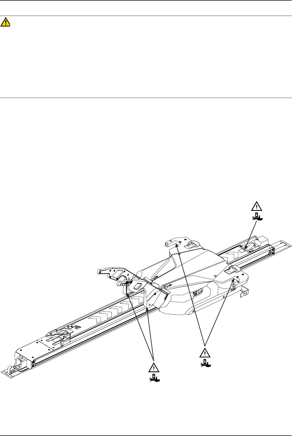
PINCH POINTS
Figure 3: Pinch Points
• To avoid the risk of equipment damage, do not slam the cot into the trolley when loading.
• To avoid the risk of equipment damage, do not push the cot into the vehicle patient compartment until the cot base
is fully retracted.
• Do not let go of the manual release until the cot locks into position at the head end. If you let go too early, then
the cot base may prevent the cot from properly locking into Power-LOAD.
• DO NOT STEAM CLEAN OR ULTRASONICALLY CLEAN THE UNIT.
• Maximum water temperature should not exceed 180°F/82°C.
• Allow unit to air dry prior to use.
• Failure to comply with these instructions may invalidate any/all warranties.
CAUTION (CONTINUED)

14 6390-009-001 REV B www.stryker.com
Return To Table of Contents
Vehicle Cot Compatibility Information
The Stryker Model 6390 Power-LOAD system is designed to be fully compatible with cots with the Power-LOAD
compatible option only. Vehicle cots which currently meet these specifications are:
• Model 6085 Performance-PRO™ XT with the Power-LOAD option (compatibility kit - 6085-700-010)
• Model 6086 Performance-PRO™ XT with the Power-LOAD option (compatibility kit - 6086-700-001)
• Model 6500 Power-PRO™ XT with the Power-LOAD option (compatibility kit - 6500-700-049)
• Model 6506 Power-PRO™ XT with the Power-LOAD option (compatibility kit - 6506-700-001)
• Model 6510 Power-PRO™ IT with the Power-LOAD option (compatibility kit - 6510-700-001)
• Model 6516 Power-PRO™ IT with the Power-LOAD option (compatibility kit - 6516-700-001)
WARNING
• Power-LOAD is designed to be compatible with the Performance-PRO XT, Power-PRO XT, and Power-PRO IT cots
with the Power-LOAD option only. In certain situations, you can use Power-LOAD as a standard antler for most
X-frame cots, but a rail clamp assembly is required for all cots without the Power-LOAD option.
• It is the responsibility of the cot operator to ensure that the cot being used in the Stryker Model 6390 Power-LOAD
system is a Power-LOAD compatible cot. Injury may result if a non-compatible cot is used in the Stryker Model
6390 Power-LOAD system.
www.stryker.com 6390-009-001 REV B 15
Return To Table of Contents
Installation Setup Procedures
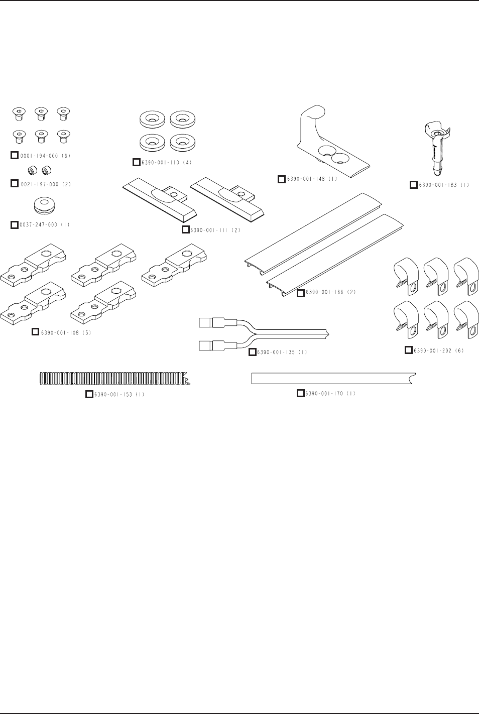
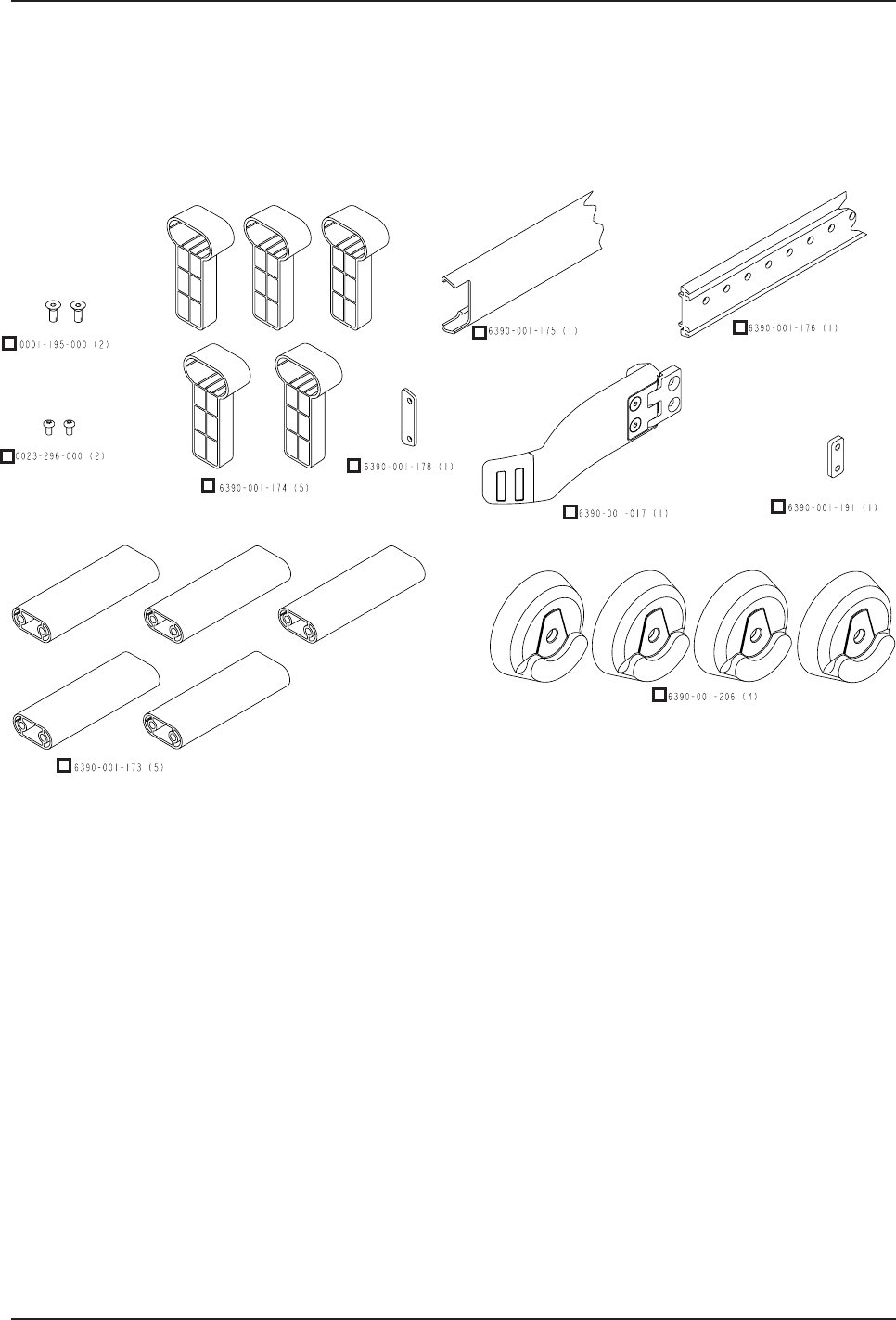
FLOOR PLATE ASSEMBLY INSTALLATION COMPONENT CHECKLIST
Follow this component checklist to ensure that you have all of the required components to properly install the Power-
LOAD system. For installation instructions, see “Installing the Floor Plate (with a Wood Floor)” on page 21.
Figure 4: Floor Plate Installation Kit Components (6390-001-055)
16 6390-009-001 REV B www.stryker.com
Return To Table of Contents
Installation Setup Procedures
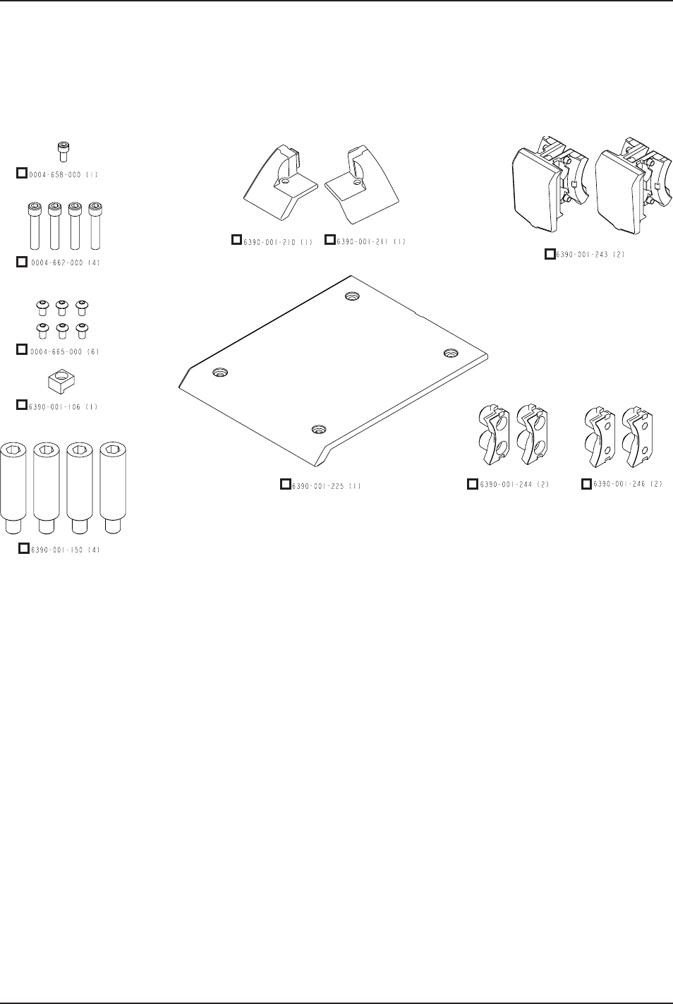
POWER-LOAD ASSEMBLY INSTALLATION COMPONENT CHECKLIST
Follow this component checklist to ensure that you have all of the required components to properly install the Power-
LOAD system. For installation instructions, see “Installing the Power-LOAD System” on page 27.
Figure 5: Power-LOAD Assembly Installation Kit Components (6390-001-054)
www.stryker.com 6390-009-001 REV B 17
Return To Table of Contents
Installation Setup Procedures
OPTIONAL WHEEL GUIDE ASSEMBLY INSTALLATION COMPONENT CHECKLIST
Follow this component checklist to ensure that you have all of the required components to properly install the Power-
LOAD system. For installation instructions, see “Installing The Optional Wheel Guide” on page 34.
Figure 6: Optional Wheel Guide Assembly Installation Kit Components (6390-027-000)

18 6390-009-001 REV B www.stryker.com
Return To Table of Contents
QUALITY SYSTEM REGULATION
The U.S. Food and Drug Administration (FDA) Code of Federal Regulations (CFR) Title 21 provides guidance regarding
the installation of devices, such as Power-LOAD. To comply with these federal regulations, each device must be
verified to have been properly installed by trained* individuals by following the inspection criteria in the “Power-LOAD
Installation Checklist” on page 38. This document must be maintained for a minimum of 7 years for each serial
number/installation.
*the Power-LOAD installation facility must maintain their own training records showing that the installer was qualified.
CFR 21 SEC. 820.170 INSTALLATION
(a) Each manufacturer of a device requiring installation shall establish and maintain adequate installation and inspection
instructions, and where appropriate test procedures. Instructions and procedures shall include directions for ensuring
proper installation so that the device will perform as intended after installation. The manufacturer shall distribute the
instructions and procedures with the device or otherwise make them available to the person(s) installing the device.
(b) The person installing the device shall ensure that the installation, inspection, and any required testing are performed
in accordance with the manufacturer’s instructions and procedures and shall document the inspection and any test
results to demonstrate proper installation.
CFR 21 SEC. 820.180 GENERAL REQUIREMENTS
All records required by this part shall be maintained at the manufacturing establishment or other location that is
reasonably accessible to responsible officials of the manufacturer and to employees of FDA designated to perform
inspections. Such records, including those not stored at the inspected establishment, shall be made readily available
for review and copying by FDA employee(s). Such records shall be legible and shall be stored to minimize deterioration
and to prevent loss. Those records stored in automated data processing systems shall be backed up.
(a) Confidentiality. Records deemed confidential by the manufacturer may be marked to aid FDA in determining
whether information may be disclosed under the public information regulation in part 20 of this chapter.
(b) Record retention period. All records required by this part shall be retained for a period of time equivalent to the
design and expected life of the device, but in no case less than 2 years from the date of release for commercial
distribution by the manufacturer.
WARNING
• Improper installation can result in injury. Install the Stryker Model 6390 Power-LOAD system as described in this
manual. Ensure that, at a minimum, your configuration with Power-LOAD is tested to meet AMD Standard 004.
• Take special precautions regarding electromagnetic compatibility (EMC) when using medical electrical equipment
like Power-LOAD. Install and place Power-LOAD into service according to the EMC information in this manual.
Portable and mobile RF communications equipment can affect the function of Power-LOAD.
Quality System Regulation for Installation
www.stryker.com 6390-009-001 REV B 19
Return To Table of Contents
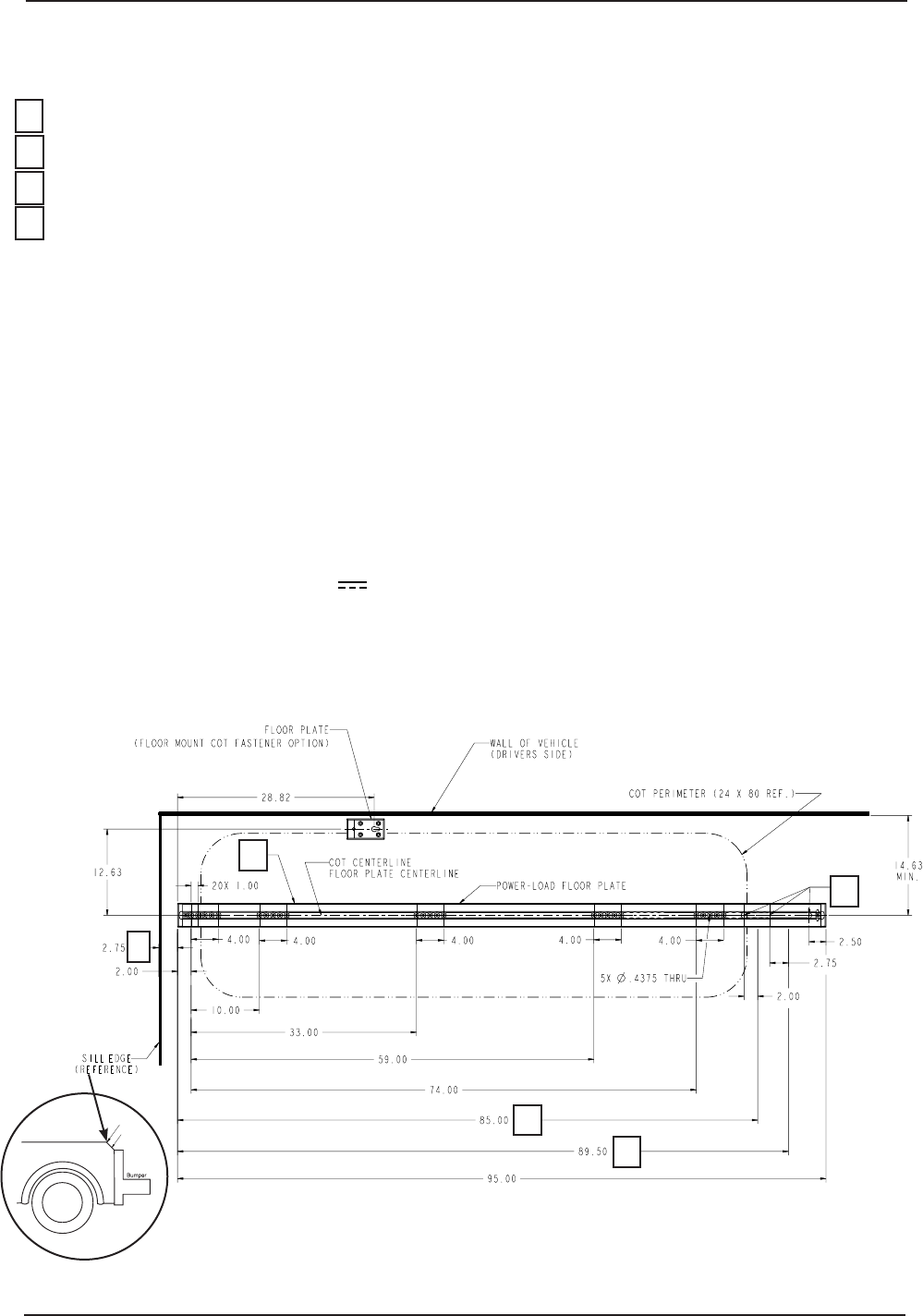
Select your configuration (see Figure 7, Figure 8, or Figure 9 for reference).
Note: All measurements are shown in inches.
1 Choose one hole to drill Ø 1/2 in (1.3 cm) through for electrical input.
2 Router depth to be 9/16 in (1.4 cm) for the floor plate pocket.
3 Floor plate may be cut shorter to either indicated length.
4 Note: The foot end of the floor plate should be 2-3/4 in (7 cm) from the location where the door sill first drops off.
• Floor plate pocket width will be approximately 2.563 in (6.5 cm).
• Bolts (not included) for the floor plate (select one bolt location from each of the five bolt patterns) are to be 3/8-16
UNC flat head cap screws, ASTM-F835 or SAE grade 8. Each bolt should have a flat washer, lock washer, and nut.
• Each bolt and supporting structure underneath must be able to withstand 2750 lb (998 kg) in upward tension and 600
lb (272 kg) in shear in all horizontal directions.
• Each bolt must be installed with a minimum of 40 ft-lb torque.
• Bolts for the antler and rail clamp plates are to be 3/8-16 UNC socket head cap screws.
Note: Antler and rail clamp plates are optional.
• Choose an unused bolt hole to drill through Ø 9/16 in (1.4 cm) for drain hole toward the foot end. Do not use the
front four drill holes.
• Electrical requirements: 12.8V-15.6V , 15A breaker, 2 conductor 10 AWG cable.
• Ensure that minimum clearance is provided from the captain’s seat. Refer to KKK-A-1822F Federal Specification for
the Star-of-Life Ambulance, section 3.10.4, for further guidance.
• You must install the optional wheel guide (6390-027-000) for Type II ambulances (see page 34).
Figure 7: Power-LOAD Floor Plate with Single Standard Floor Mount Cot Fastener Floor Plate (Optional)
Sill
Sill Edge
4
3
2
1
3
Floor Plate Installation Guidelines