Subaru EX40 Parts Manual EP6516 Rev 06 12 User To The 31061a7a B23f 4734 Bfc4 8ce7411517b8
User Manual: Subaru EX40 to the manual
Open the PDF directly: View PDF ![]() .
.
Page Count: 33

PARTS
MANUAL
Models
EX40
ENGINES
PUB-EP6516
Rev. 04/14
© Copyright 2009 Robin America, Inc.
Robin America, Inc.
905 Telser Road, Lake Zurich, IL 60047 • Phone: 847-540-7300 • Fax:847-438-5012
e-mail: sales@robinamerica.com • www.subarupower.com
HOW TO USE THIS MANUAL
Robin engines are identifi ed by MODEL, SPECIFICATION, and CODE NUMBER. For each
model there may be many different versions called specifi cations. Each specifi cation will be
unique in some way. The difference may only be the paint color or it may have a different type
of PTO or some other signifi cant difference.
In order the identify the correct service part number, it is important to confi rm the specifi ca-
tion and code numbers for your engine. The specifi cation and code number together are
know as the PRODUCT NUMBER.
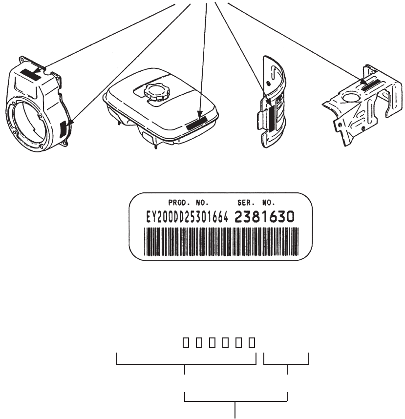
All Robin 4 cycle engines have a Product Number label similar to the label illustrated below.
The Product Number Label has a 15 digit alphanumeric string that consists of the
SPECIFICATION (SPEC) number (11 digits) and the CODE number (4 digits). Please
note the illustration below:
X X X X
SPEC NO. (11 digits) CODE NO. (4 digits)
PRODUCT NO. (15 digits)
E X 4 0 0
MANUAL LAYOUT
1. SECTION NAME Parts are broadly classifi ed according to their functions.
Refer to the Group Index (table of contents) for respective section name.
2. FIG. No. The FIG. number indexes the reference and part numbers to the illustration. Figure numbers
that vary only in the tens place (i.e..: 700 and 710) are in a group of the same section
(i.e..:Electrical Device Group).
3. REF. No . The Reference number identifi es the part illustration with the corresponding part number in the
part list.
4. SUBASSEMBLY SUBASSEMBLY parts of part assembly are listed below the assembly part. The subassembly
part reference number is indicated by the number led by "-" such as "-1", "-2".
5. PART NUMBER It is the number assigned for sales unit. Use the PART No. when making an order.
6. DESCRIPTION It is designation of the part.
7. QTY. Quantity of each part used for each product.
8. REMARKS This gives a distinctive feature and/or a supplementary comment for the type, the specifi cation,
and the part concerned. It also shows part number(s) interchangeable for the part.
9. FROM-TO This section shows the CODE No. to indicate the history of progress in which improved parts
have been introduced in the product. The FROM-TO CODE No. helps to identify PART No.
being employed in the product concerned. See the examples below:
- The part is used in the product irrespective of CODE No.
2101- The part is used in the products with CODE No. of 2101 and after this number.
- 2100 The part is used in the products with CODE No. of 2100 and before this number.
1
23
4
16792
8
3
5
4

GROUP INDEX
Group Name Page
CRANKCASE GROUP ............................................................................... 6
CRANKSHAFT GROUP ............................................................................. 8
INTAKE and EXHAUST GROUP .............................................................. 10
GOVERNOR GROUP .............................................................................. 14
COOLING and STARTING GROUP ......................................................... 16
FUEL, LUBRICANT GROUP .................................................................... 18
CARBURETOR GROUP .......................................................................... 20
ELECTRIC DEVICE GROUP .................................................................. 22
ACCESSORY GROUP ............................................................................. 24
SYMBOL DESCRIPTION
AY ...........................ASSEMBLY
CP ...........................COMPLETE
EX ...........................EXPORT (from Japan)
FIG. .........................FIGURE
FR. ..........................FRONT
" ..............................INCH
INCL. ......................INCLUDE
~L ............................LITER
L= ...........................LENGTH (in. mm)
L.H. (LH) .................LEFT-HAND SIDE
MECH ..................... MECHANICAL
NO (NON) ...............NONE
OPT.........................OPTIONAL
O.S. ........................OVER SIZE
SYMBOL DESCRIPTION
P= ...........................PITCH (in mm)
P.T.O. (PTO) ...........POWER TAKE OFF
REF. ........................REFERENCE
R.H. (RH) ................RIGHT HAND SIDE
RR. .........................REAR
STD. .......................STANDARD
SW ..........................SWITCH
T= ...........................THICKNESS (in mm)
UN ..........................UNIT
U.S..........................UNDER SIZE
~V ........................... VOLTAGE
~W .......................... WATT
W/ ...........................WITH
W/O ........................WITHOUT
INDEX OF DESCRIPTION SYMBOLS
EX40 - 6 - 08-09
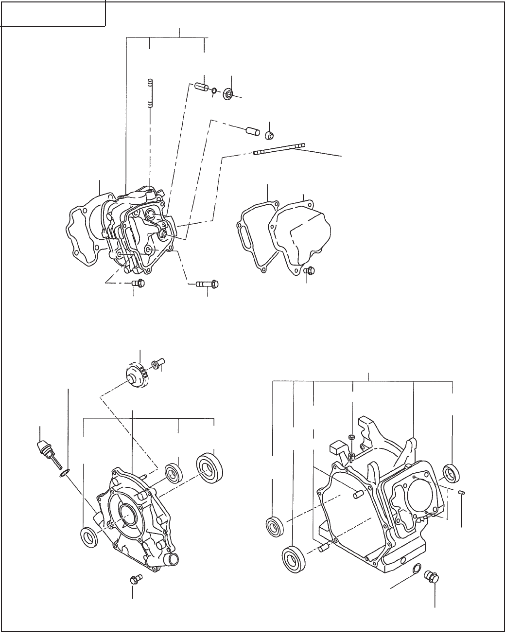
SECTION 1 CRANKCASE GROUP
FIG. 100
260
250
270
280
220
210
230
240
300
10
50
40
45
75 30
700
90
80
70 20 28
27 26
60
620
631 630
690 680
710
610

EX40 - 7 - 08-09
Ref. Part Number Description Qty Remarks To-From Fig.
SECTION 1 CRANKCASE GROUP
10 20B-10102-11 Crankcase Cp 1 100
20 20B-14202-03 Valve Guide 2 100
26 132-07AA0-50 Seal, intake valve 1 100
27 056-51000-50 Clip 1 100
28 263-35341-03 Retainer Plate 1 100
30 044-03500-90 Oil Seal 1 100
40 060-03502-40 Ball Bearing 1 100
45 X60-01500-11 Ball Bearing 1 100
50 277-15011-03 Pipe Knock 2 100
60 010-50603-51 Stud, intake 2 100
70 010-50802-90 Stud, exhaust 2 100
75 044-00800-10 Oil Seal 1 100
80 040-11400-30 Plug 1 100
90 021-11400-20 Gasket 1 100
210 20B-11002-11 Main Bearing Cover Cp 1 100
220 044-03500-90 Oil Seal 1 100
230 060-03502-40 Ball Bearing 1 100
240 X60-01500-11 Ball Bearing 1 100
250 20B-45003-01 Governor Gear Cp 1 100
260 277-41901-03 Governor Sleeve 1 100
270 279-63601-30 Oil Gauge Ay 1 8157- 100
224-63601-03 Oil Gauge 1 -8156 100
280 021-32000-50 Gasket 1 100
300 011-00803-40 Flange Bolt 8 100
610 20B-13001-01 Cylinder Head Cp 1 100
620 20B-15001-03 Gasket, cylinder head 1 100
630 011-01000-40 Flange Bolt 4 100
631 001-04083-50 Flange Bolt 2 100
680 20B-15501-01 Rocker Cover Cp 1 100
690 20B-16001-03 Gasket, rocker cover 1 100
700 031-00600-20 Dowel Pin 2 100
710 011-00600-20 Flange Bolt 4 100
960 20B-99001-07 Gasket Set 1 100
EX40 - 8 - 08-09
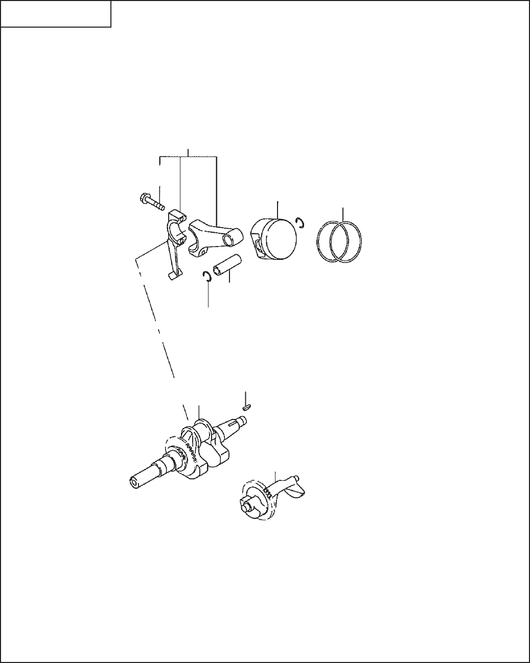
SECTION 2 CRANKSHAFT GROUP
FIG. 200
310
320
360 370
380
350
10
70
390

EX40 - 9 - 08-09
Ref. Part Number Description Qty Remarks To-From Fig.
SECTION 2 CRANKSHAFT GROUP
10 20B-20901-01 Crankshaft Cp 1 1" Key 200
20B-21201-01 Crankshaft Cp 1 7/8" Taper 200
20B-21001-01 Crankshaft Cp 1 1" Pump 200
70 005-32054-01 Woodruff Key 1 200
310 20B-22501-00 Connecting Rod Ay 1 200
320 001-05084-00 Connecting Rod Bolt 2 200
350 263-23301-33 Piston Pin 1 200
360 20B-23401-H3 Piston 1 Std 200
360 20B-23403-H3 Piston 1 Oversize 0.25mm 200
360 20B-23404-H3 Piston 1 Oversize 0.50mm 200
370 20B-23501-07 Piston Ring Set 1 Std 200
370 20B-23502-07 Piston Ring Set 1 Oversize 0.25mm 200
370 20B-23503-07 Piston Ring Set 1 Oversize 0.50mm 200
380 056-52100-20 Clip 2 200
390 20B-24101-03 Balancer Shaft 1 200
EX40 - 10 - 08-09
SECTION 3 INTAKE and EXHAUST GROUP
FIG. 300
350
310
365
315
317
340
80
90
290
225
241 231
210
240
230
60
70
220
95
320
361
170
25
27
37 35 34 38
166 163 160
10
150
370

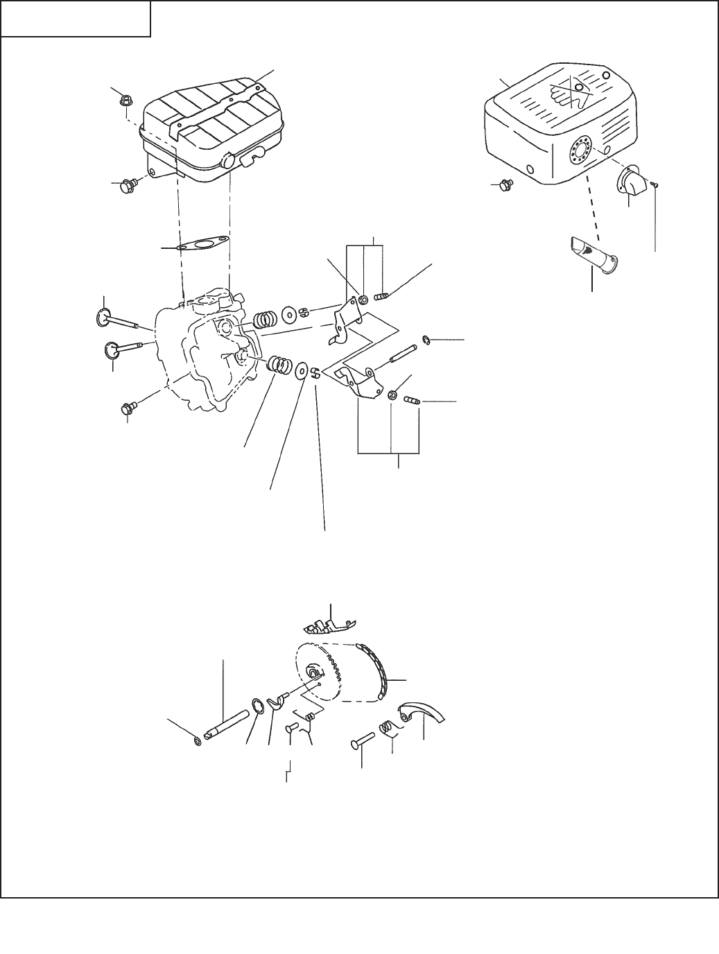
SECTION 3 INTAKE and EXHAUST GROUP
Ref. Part Number Description Qty Remarks To-From Fig.
10 20B-31601-01 Camshaft Cp 1300
25 20B-35101-03 Pin, camshaft 1300
27 024-00700-20 O ring 1300
34 005-19041-00 Pin, spring 2300
35 277-36401-03 Release lever 1300
37 20B-36501-03 Clip 1300
38 277-38702-03 Return Spring 1300
60 246-33611-03 Valve Spring 2300
70 246-33711-13 Spring Retainer 2300
80 20B-33401-H3 Intake Valve 1300
90 20B-33501-H3 Exhaust Valve 1300
95 246-35501-03 Collet Valve 4300
150 20B-35601-H1 Timing Chain 1300
160 277-36911-03 Tentioner 1300
163 277-37101-03 Spring, tentioner 1300
166 277-36902-03 Pin, tentioner 1300
170 277-36913-13 Chain Guide 1300
200 20B-35001-01 Pin, rocker 1300
210 003-13060-00 Clip 1300
220 20B-36101-00 Rocker Arm Ay, intake 1300
225 20B-36102-10 Rocker Arm Ay, exhaust 1300
230 014-90500-20 Adjust Screw 1300
231 014-90500-20 Adjust Screw 1300
240 017-00500-30 Nut 1300
241 017-00500-30 Nut 1300
290 011-00600-20 Flange Bolt 1300
310 20B-30101-J2 Muffler 1300
315 20B-37001-01 Deflector Cp 1300
317 015-00400-60 Tapping Screw 3300
320 20B-34201-11 Muffler Cover Cp 1300
340 20B-35201-03 Gasket, muffler 1300
350 980-20082-80 Flange Nut 2300
361 011-00600-10 Flange Bolt 5300
365 011-00803-20 Flange Bolt 1300
370 267-37601-01 Spark Arrestor 1300
EX40 - 11 - 04-14

EX40 - 12 - 08-09
SECTION 3 INTAKE and EXHAUST GROUP
FIG. 310$
200 290
295
280
250
510
520
270
220
260
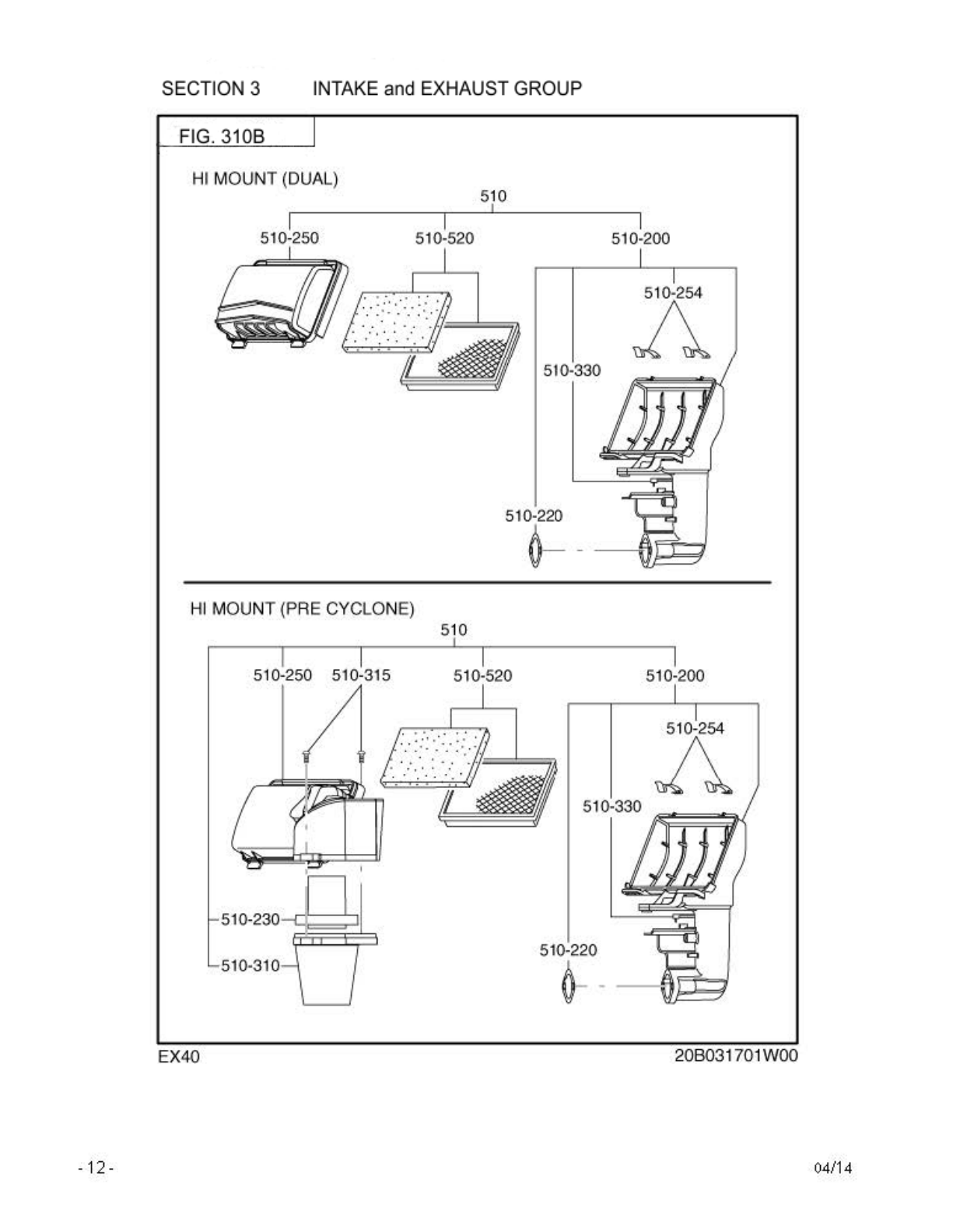

SECTION 3 INTAKE and EXHAUST GROUP
Ref. Part Number Description Q1ty Remarks To-From Fig.
510 20B-32611-H0 Air Cleaner Ay 1Dual 310A
510 20B-32651-H0 Air Cleaner Ay 1310B
200 20B-32630-H8 Cleaner Body 1310A
220 20B-32720-H8 Gasket, packing 1310A&B
250 20B-32640-H8 Cover 1310A
250 20B-32641-H8 Cover 1310B
254 20B-32680-H8 Clip1 2310B
260 20B-32850-H8 Cap 1310A
270 20B-32650-H8 Bolt 1310A
280 X85-11001-80 Rubber Pipe, breather 1310A
290 002-38060-00 Flange Nut 2310A
295 001-04061-60 Flange Bolt 1310A
520 20B-32610-H7 Element 1310A&B
EX40 - 13 - 04-14
EX40 - 14 - 08-09
SECTION 4 GOVERNOR GROUP
FIG. 400
80
30
40
450
340
345
310
311
355
480
10
70
60
485
360
370
435 396
395
436
50
90
20 50
490

EX40 - 15 - 08-09
Ref. Part Number Description Qty Remarks To-From Fig.
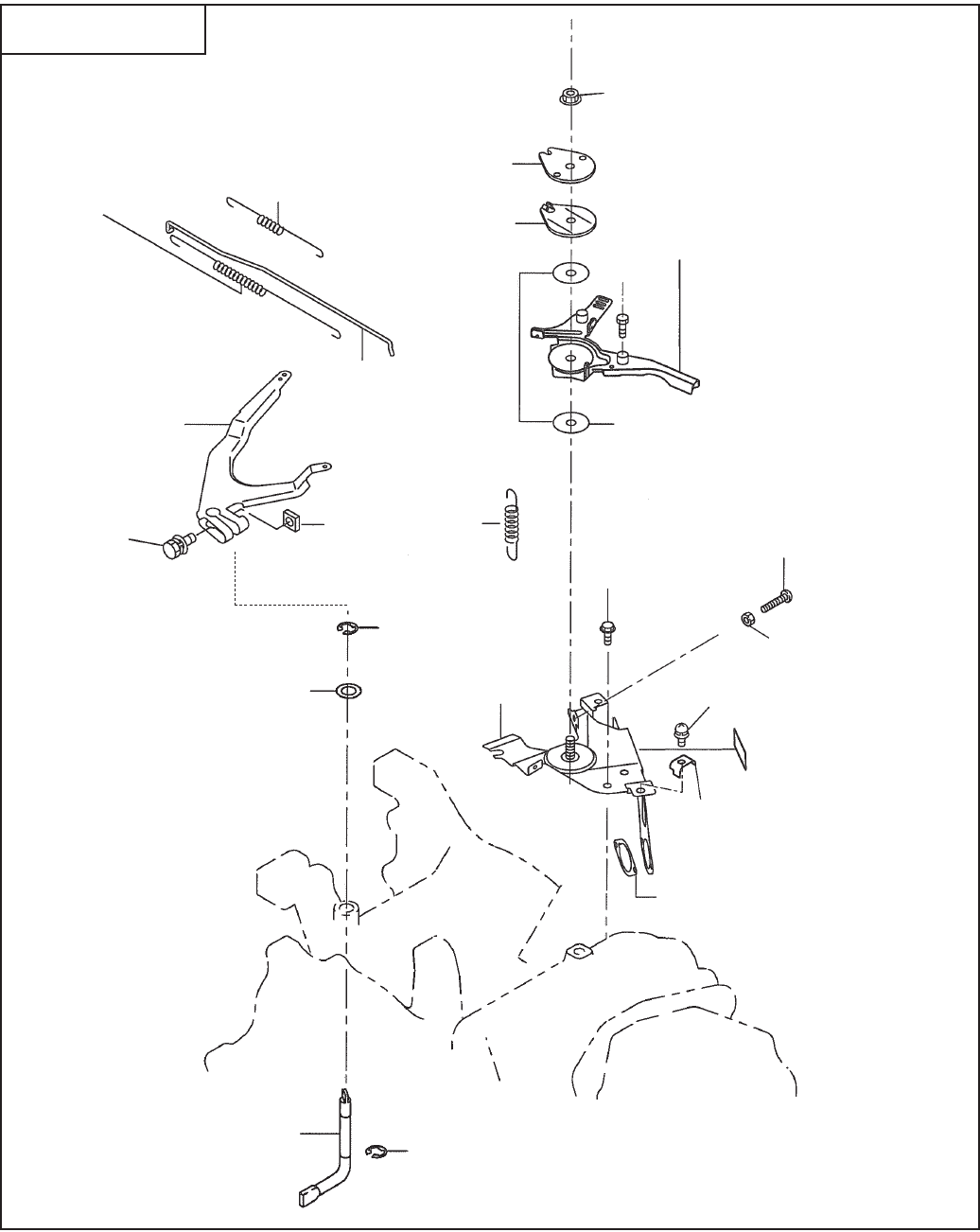
SECTION 4 GOVERNOR GROUP
10 20B-42301-03 Governor Lever 1 400
20 20B-42201-13 Governor Shaft 1 400
30 20B-42701-01 Governor Rod 1 400
40 20B-42801-13 Rod Spring 1 400
50 003-13060-00 Clip 2 400
60 001-14062-50 Bolt and Washer 1 400
70 018-60600-20 Nut 1 400
80 20B-42503-13 Governor Spring 1 400
90 003-11080-00 Washer 1 400
310 20B-43301-01 Speed Control Lever Cp 1 Std 400
20B-43351-03 Speed Control Lever 1 Generator 400
311 011-60400-30 Bolt, swivel 1 400
340 227-43501-13 Stop Plate 1 400
345 227-45002-03 Spring Washer 1 400
355 021-70600-30 Friction Washer 2 400
360 004-31061-80 Screw, panhead 1 400
370 002-27060-00 Nut 1 400
395 277-43902-03 Clamp 1 400
396 013-10500-30 Screw and Washer 1 400
435 20B-46001-11 Speed Control Bracket Cp 1 400
436 20B-35903-03 Gasket 3 1 400
450 002-35060-00 Self Lock Nut 1 400
480 267-45101-03 Return Spring 1 400
485 011-00600-20 Flange Bolt 1 400
EX40 - 16 - 08-09
SECTION 5 COOLING and STARTING GROUP
FIG. 500
707
705
706
220
210
20
80
60 40
16
10
15
17
61
81
18

EX40 - 17 - 08-09
Ref. Part Number Description Qty Remarks To-From Fig.
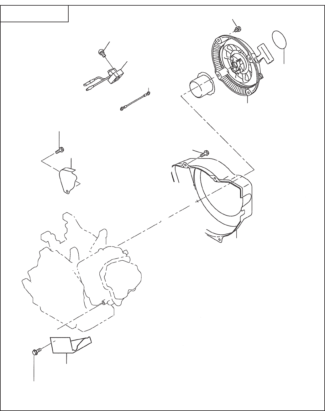
SECTION 5 COOLING and STARTING GROUP
490 277-96107-03 Label, hi-low 1 400
10 20B-51201-H1 Blower Housing 1 500
15 20B-55101-02 Recoil Bracket Un 1 500
16 010-00804-40 Bolt 2 500
17 010-00804-50 Bolt 2 500
18 002-38060-00 Flange Nut 4 500
20 073-20054-70 Label, trademark 1 500
40 001-04061-60 Flange Bolt 5 500
60 001-65081-20 Bolt 1 500
61 20B-52702-H1 Baffl e 2, head 1 500
80 279-52711-11 Baffl e 1, case 1 500
81 011-00600-20 Flange Bolt 3 500
220 013-00602-81 Bolt and Washer Ay 4 500
705 KU3-11077-01 Float C/U Cp11 1 500
706 20B-73102-01 Wire 2 Cp 1 500
EX40 - 18 - 08-09
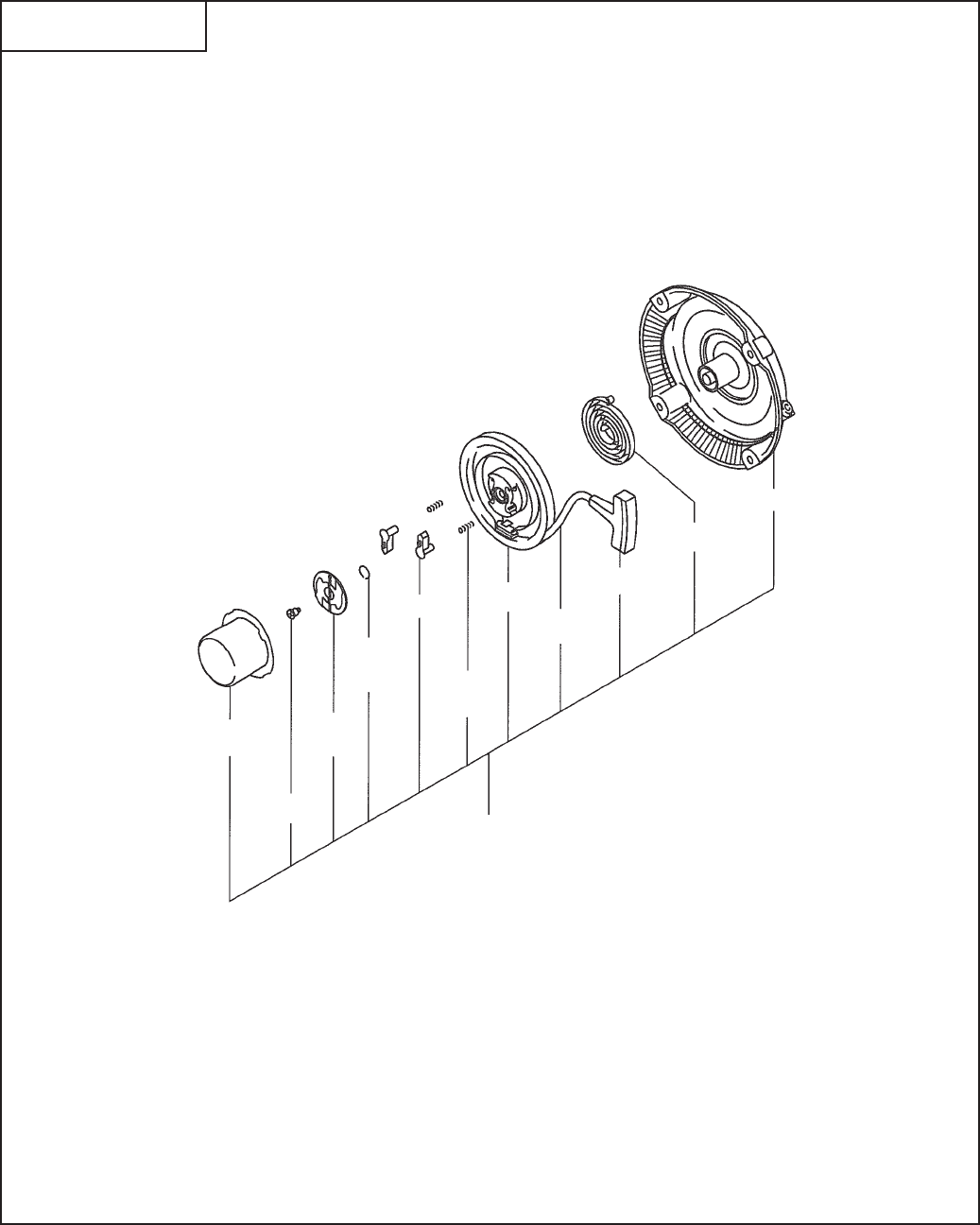
SECTION 5 COOLING and STARTING GROUP
FIG. 520
-1
-4
-7
210
-5
-9
-6
-11
-8
-2
-3
-10

EX40 - 19 - 08-09
Ref. Part Number Description Qty Remarks To-From Fig.
SECTION 5 COOLING and STARTING GROUP
210 20B-50301-00 Recoil Starter Ay 1 520
-1 20B-50145-08 Starter Pulley 1 520
-2 261-50100-08 Starter Knob 1 520
-3 20B-50110-08 Starter Rope 1 520
-4 20B-50101-08 Set Screw 1 520
-5 161-50150-08 Ratchet Guide 1 520
-6 227-50135-08 Return Spring 2 520
-7 227-50131-08 Friction Spring 1 520
-8 277-50155-08 Spiral Spring 1 520
-9 161-50125-08 Ratchet 2 520
-10 20B-50120-08 Reel 1 520
-11 20B-50150-08 Starter Case 1 520
EX40 - 20 - 08-09
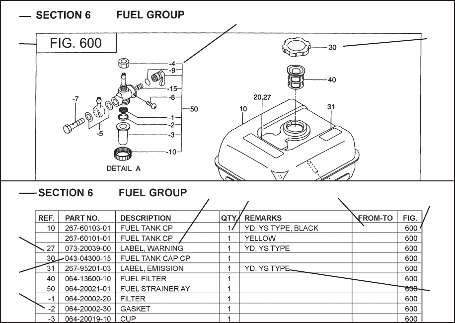
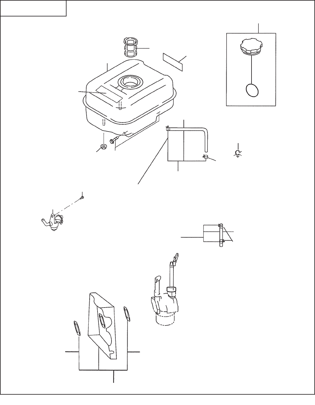
SECTION 6 FUEL, LUBRICATION GROUP
FIG. 600
40 23
30
10
20
52
60 63
59
53
51
54
50
58
55 56
57
210
560 550
540

EX40 - 21 - 08-09
Ref. Part Number Description Qty Remarks To-From Fig.
SECTION 6 FUEL, LUBRICATION GROUP
707 004-36041-20 Screw and Washer Ay 2 500
10 20B-60102-01 Fuel Tank Cp 1 600
20 073-20051-81 Label, warning 1 600
23 20B-95101-03 Label, model 1 600
30 X43-04401-61 Fuel Tank Cap Cp 1 600
40 X64-13600-10 Fuel Filter 1 600
50 X64-20122-00 Fuel Strainer Ay 1 600
51 267-62604-11 Fuel Pipe Cp 1 fuel tank strainer 600
52 X85-10614-91 Rubber Pipe 1 600
53 X56-11100-60 Hose Clamp 1 fuel pipe, strainer 600
54 056-11200-40 Hose Clamp 1 fuel pipe, tank 600
55 20B-62601-01 Fuel Pipe Cp 1 strainer, carb 600
56 085-10620-90 Rubber Pipe 1 600
57 056-11000-30 Hose Clamp 2 fuel pipe 600
58 011-00600-20 Flange Bolt 1 600
59 056-81200-10 Clamp 1 600
60 002-38080-00 Flange Nut 2 600
63 011-00802-50 Flange Bolt 2 600
540 20B-32901-J1 Insulator Cp 1 600
550 20B-35901-H3 Gasket 1, insulator 1 600

EX40 - 22 - 08-09
SECTION 6 FUEL, LUBRICATION GROUP
FIG. 610

EX40 - 23 - 08-09
Ref. Part Number Description Qty Remarks To-From Fig.
SECTION 6 FUEL, LUBRICATION GROUP
560 20B-35902-H3 Gasket 2, insulator 1 600
210 20B-62301-00 Carburetor Ay 1 Std 640
EX40 - 24 - 08-09
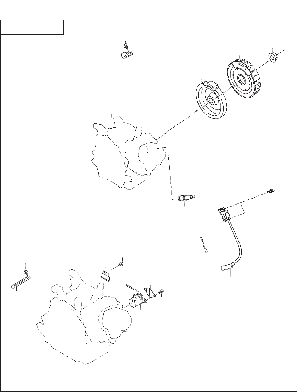
SECTION 7 ELECTRIC DEVICE GROUP
FIG. 700
770
775
740
700
733
385
384
15 16
10
785
780
100
30
50
110
11
35
12
20

EX40 - 25 - 08-09
Ref. Part Number Description Qty Remarks To-From Fig.
SECTION 7 ELECTRIC DEVICE GROUP
20B-62302-00 Carburetor Ay 1 Generator 640
10 20B-79230-H1 Flywheel Cp 1 Std 700
20B-79241-H1 Flywheel Cp 1 15 Watt 700
11 20B-79430-H1 Ignition Coil 1 700
12 20B-79301-H1 Charge Coil 1 15 Watt 700
15 20B-54101-H3 Cooling Blower 1 700
16 018-01800-10 Flange Nut 1 700
20 20B-71002-03 Ring Gear 1 700
30 001-14062-50 Bolt and Washer Ay 2 700
35 004-35062-00 Screw and Washer Ay 2 700
50 20B-73101-01 Wire 1 1 700
100 065-01401-50 Spark Plug 1 700
110 065-50003-11 Spark Plug Cap 1 700
384 056-60002-50 Clamp 1 700
385 011-00600-10 Flange Bolt 1 700
700 279-76301-51 Oil Sensor 1 700
733 277-75801-03 Shield Plate 1 700
740 013-00602-60 Bolt and Washer 2 700
770 20B-75501-03 Wire Clamp 1 700
775 015-20600-50 Tapping Bolt 1 700
780 214-79006-01 Clamp Cp 1 stop wire 700
785 011-00600-10 Flange Bolt 1 clamp 700
EX40 - 26 - 08-09
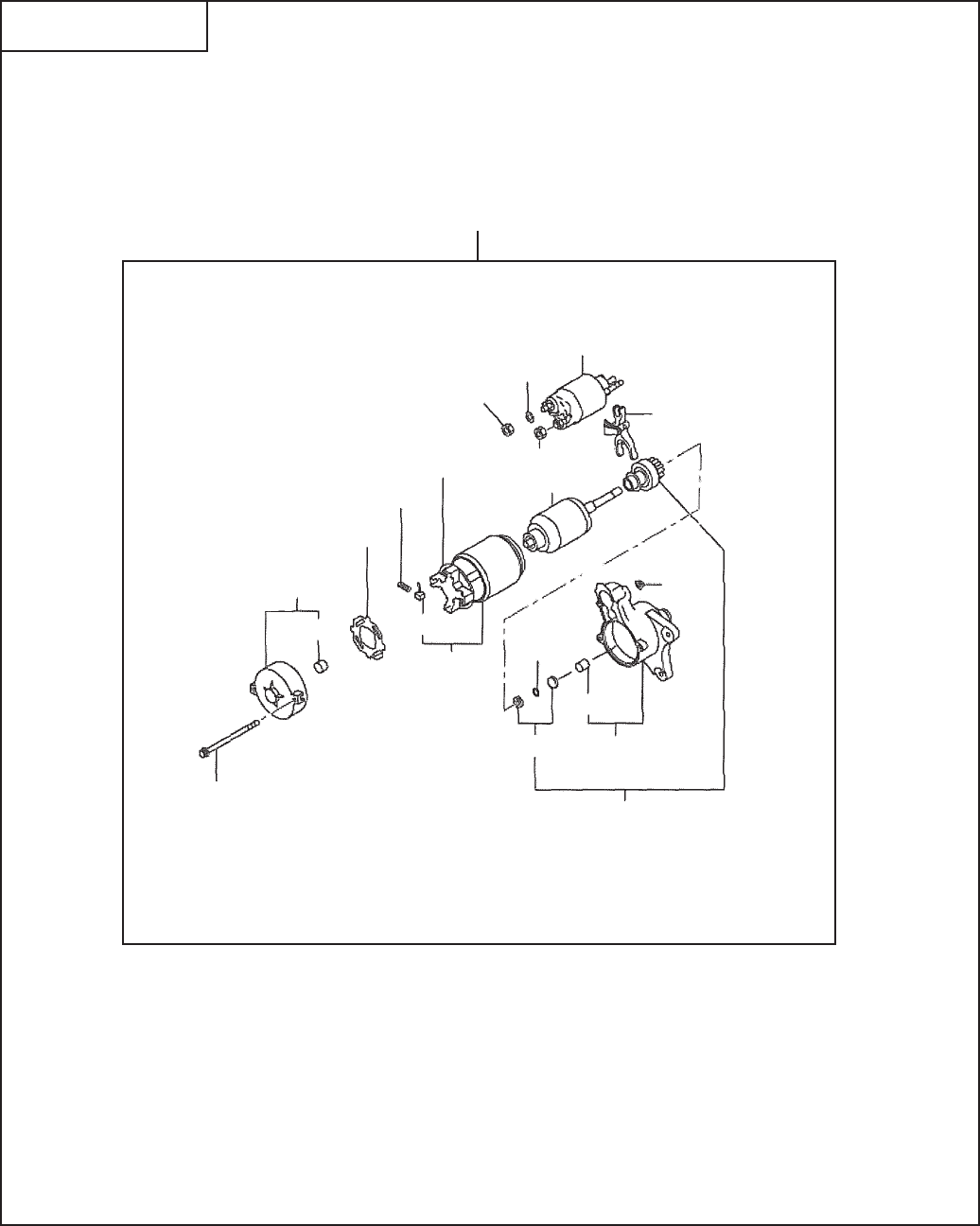
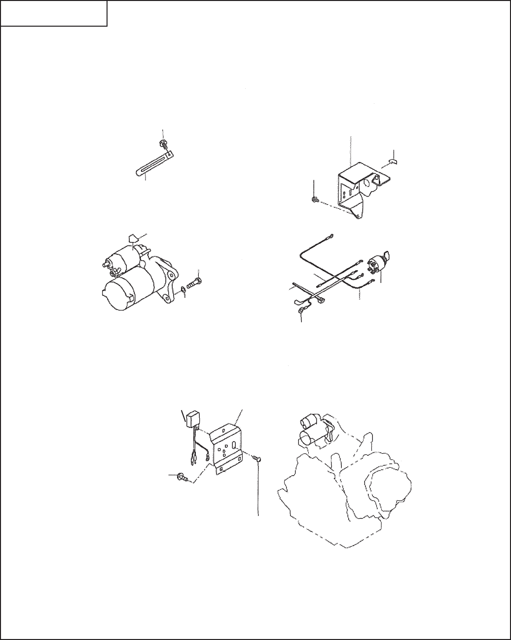
SECTION 7 ELECTRIC DEVICE GROUP - ELECTRIC STARTER
FIG. 710
1
13
19
20 12
18
6
4
3
5
10
11
17
15
9
14 8
7
16
2
120

EX40 - 27 - 08-09
Ref. Part Number Description Qty Remarks To-From Fig.
SECTION 7 ELECTRIC DEVICE GROUP - ELECTRIC STARTER
120 279-70502-00 Starting Motor Ay 1 710
-1 209-70550-08 Yoke Cp 1 710
-2 209-70551-08 Brush 4 710
-3 209-70545-08 Brush Spring 4 710
-4 209-70530-08 Brush Holder 1 710
-5 209-70552-08 Insulator 1 710
-6 209-70554-08 Armature Ay 1 710
-7 209-70521-08 Over Running Clutch Cp 1 710
-8 279-70550-08 Housing Cp 1 710
-9 209-70511-08 Bush 1 710
-10 209-70505-18 Frame Cp 1 710
-11 209-70510-08 Bush 1 710
-12 209-70525-08 Lever 1 710
-13 279-70515-18 Magnet Switch Cp 1 710
-14 234-70555-08 Pinion Stopper 1 710
-15 209-70557-18 Snap Ring 1 710
-16 209-70558-08 Through Bolt 2 710
-17 949-29970-02 Nut 2 710
-18 209-70560-08 Nut 1 710
-19 107-70652-08 Spring Washer 1 710
-20 211-70584-08 Nut 1 710
EX40 - 28 - 08-09
SECTION 7 ELECTRIC DEVICE GROUP - CONTROL BOX
FIG. 720
387
386
200
388
210
385
55
220
335
260
190
130
131
387
385
230
240

EX40 - 29 - 08-09
Ref. Part Number Description Qty Remarks To-From Fig.
SECTION 7 ELECTRIC DEVICE GROUP - CONTROL BOX
55 277-73105-01 Wire 5 1 720
130 214-79007-01 Bolt, starter 2 720
131 003-10080-00 Washer 2 720
190 073-20044-80 Label, battery 1 720
200 20B-75101-01 Control Box Cp 1 720
210 073-20044-70 Label, starter switch 1 720
220 066-00003-30 Switch Ay 1 720
-1 066-00099-80 Key 1 720
230 277-71401-01 Diode Rectifi er Cp 1 720
240 044-35061-00 Screw and Washer Ay 1 720
260 277-73103-11 Wire 3 Cp 1 720
335 277-73104-01 Wire 4 Cp 1 720
385 056-30000-60 Wire Band 1 720
385 20B-76511-01 Bracket Cp, SEL 1 720
386 056-60002-50 Clamp, sel 1 720
387 011-00600-20 Flange Bolt 3 720
388 013-50600-10 Bolt and Washer Ay 2 720
EX40 - 30 - 08-09
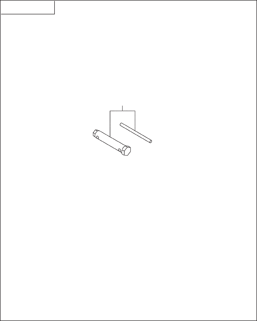
SECTION 9 ACCESSORY GROUP
FIG. 900

EX40 - 31 - 08-09
Ref. Part Number Description Qty Remarks To-From Fig.
SECTION 9 ACCESSORY GROUP
10 224-90303-00 Accessory Tool Kit 1 900

Robin America, Inc
905 TFMTFS3PBEt-BLF;VSJDI*- 60047
1IPOFt'BY
FNBJMTBMFT!TVCBSVQPXFSDPNtXXXTVCBSVQPXFS.com
PRINTED IN THE USA
