Summation Research ST326-4-I TELEMETRY Transmitter User Manual SUMMATION RESEARCH INCORPORATED

Summation Research Inc TELEMETRY Transmitter SUMMATION RESEARCH INCORPORATED

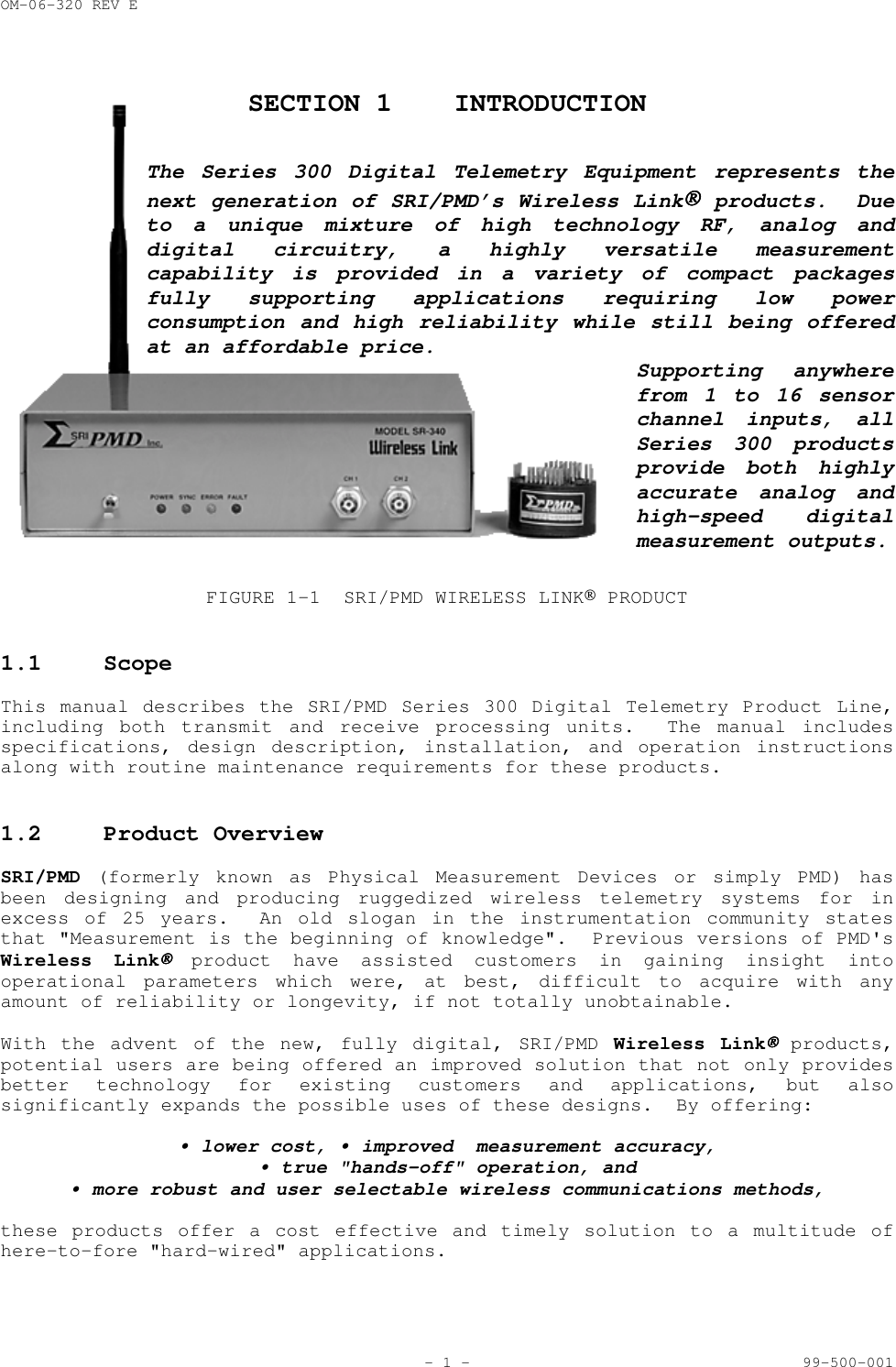
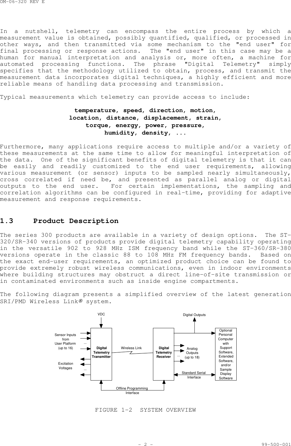
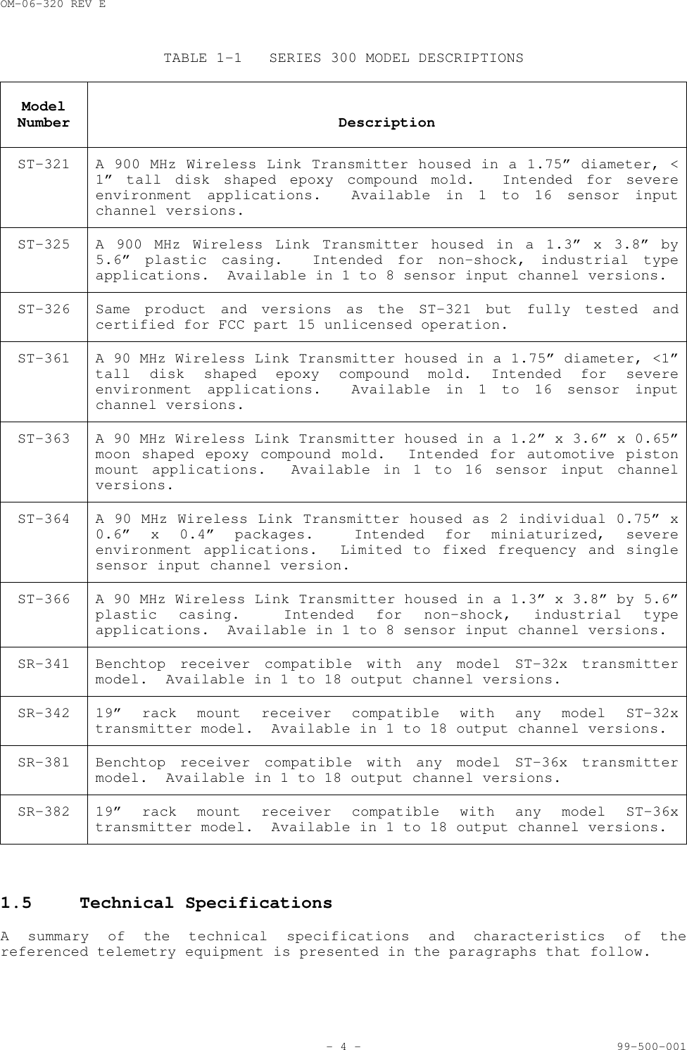
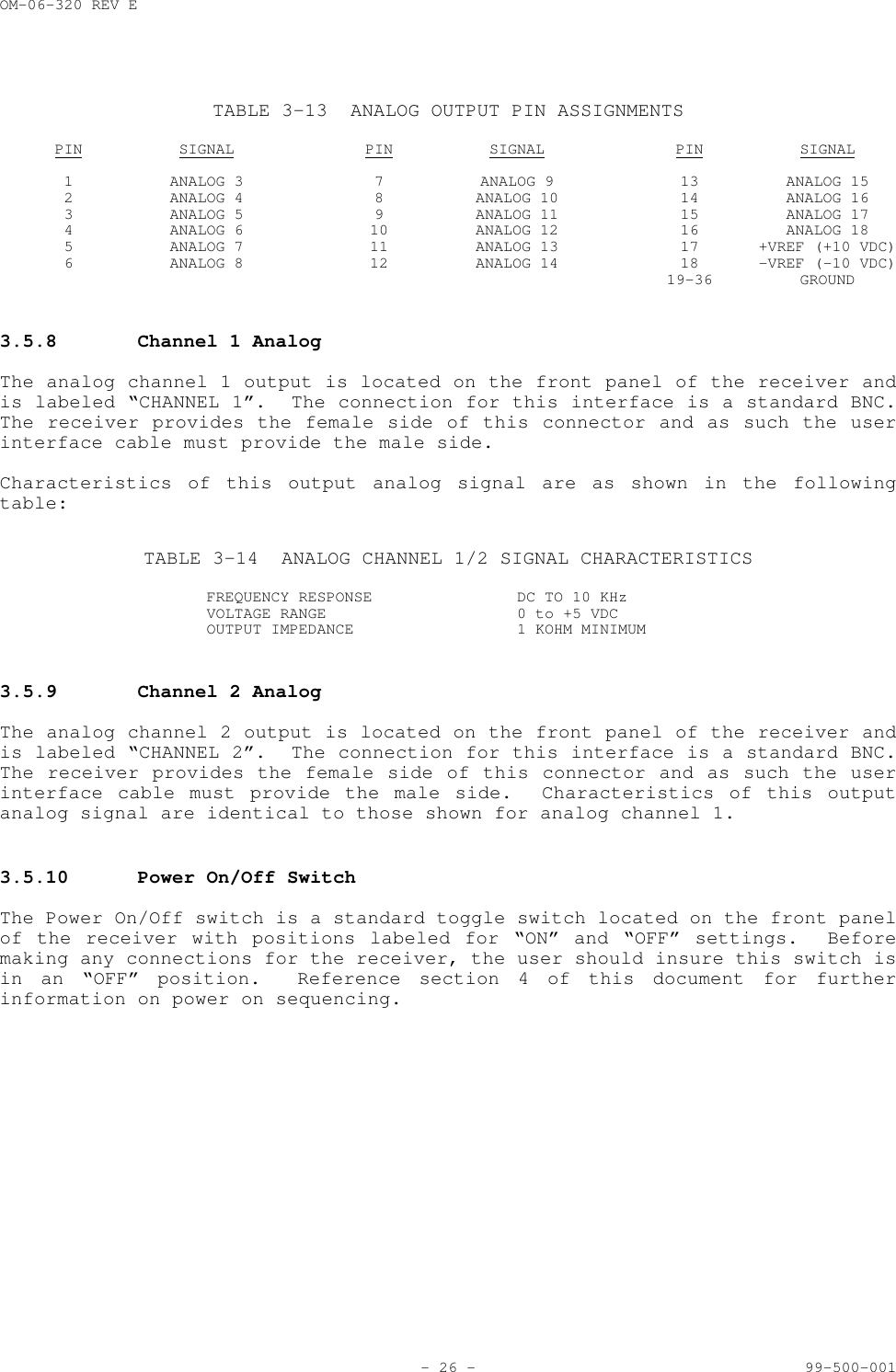
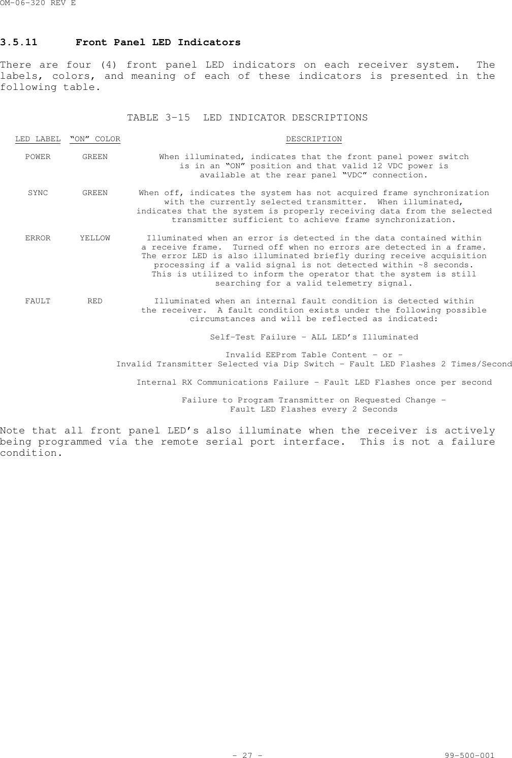
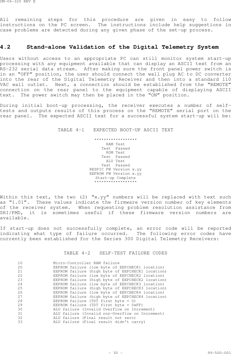
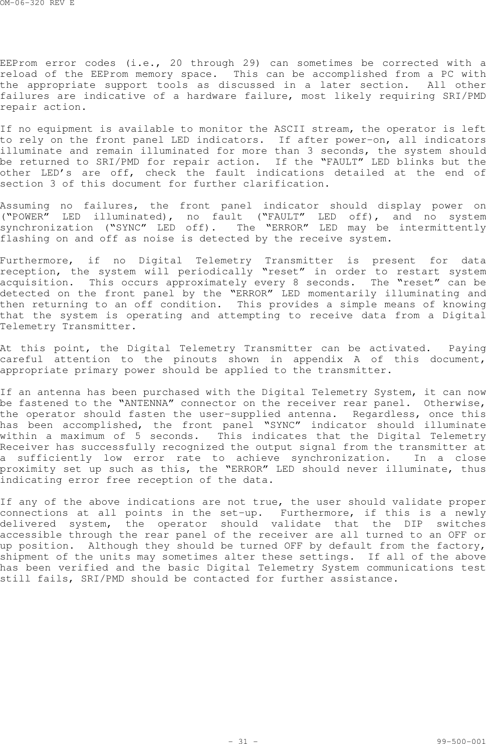
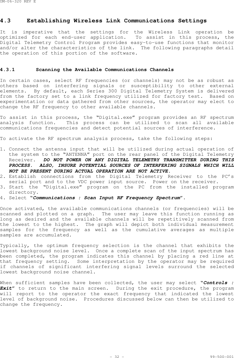
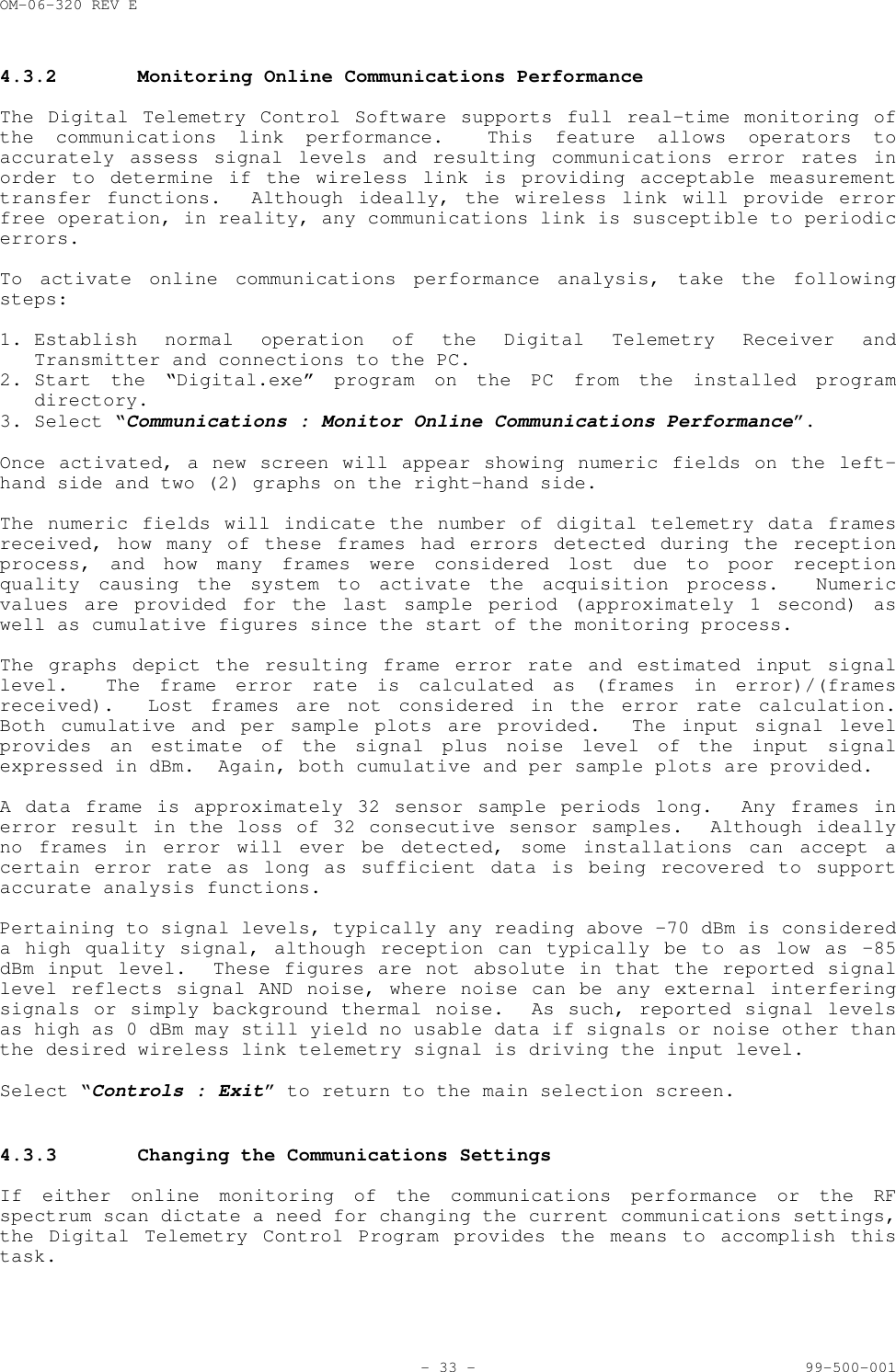
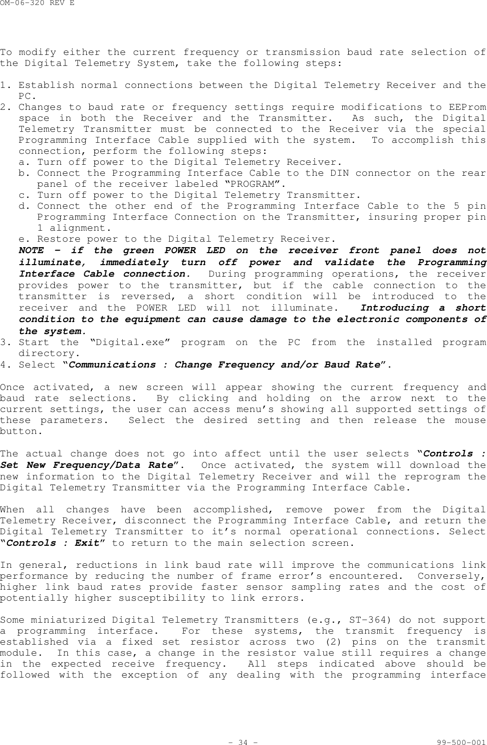
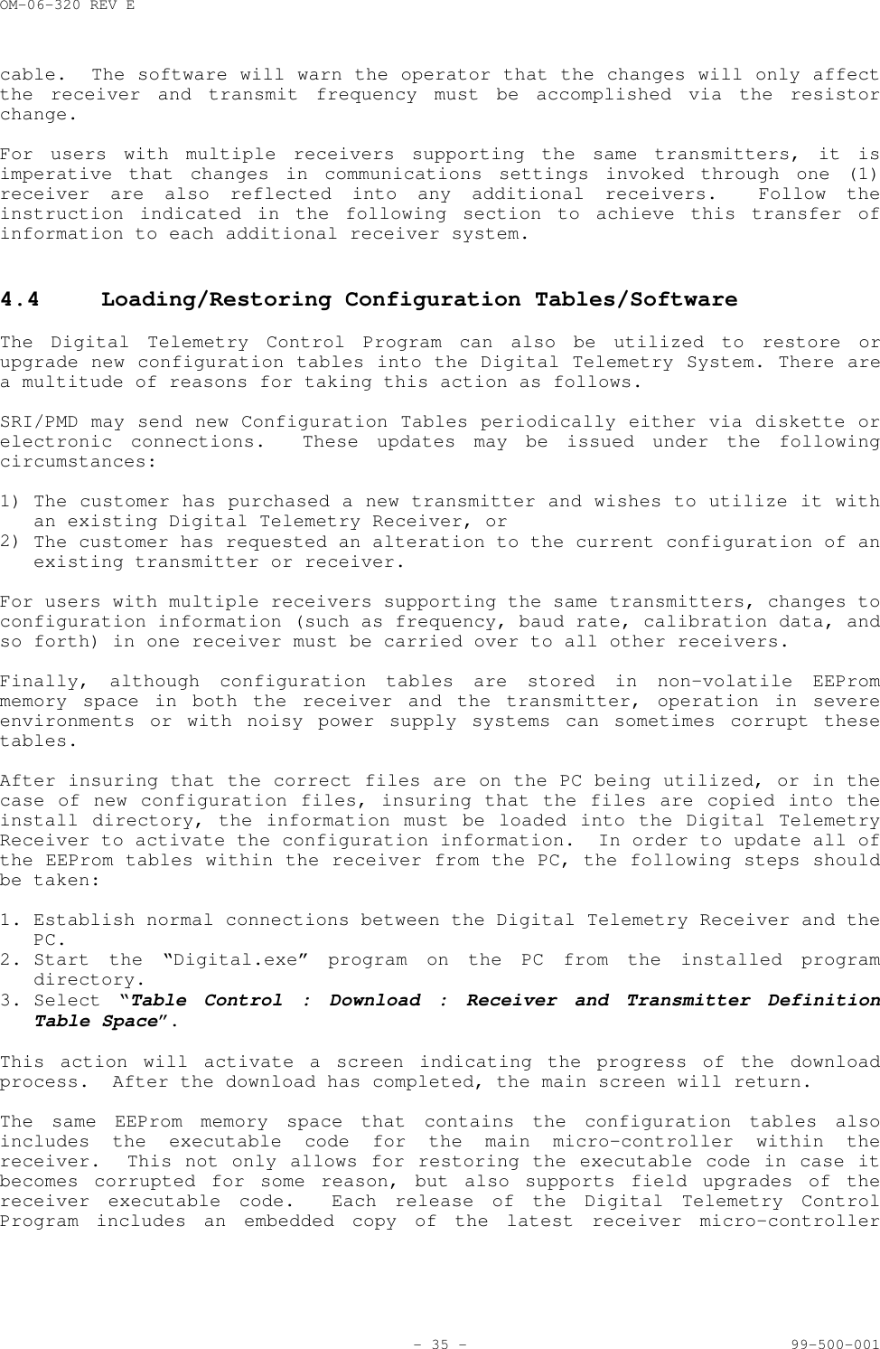
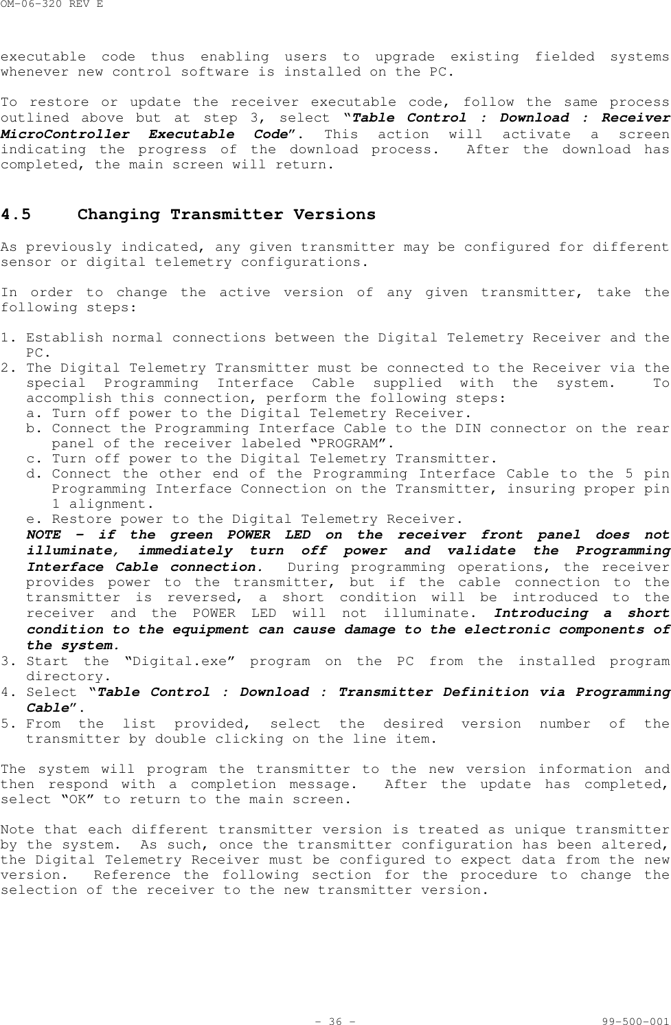
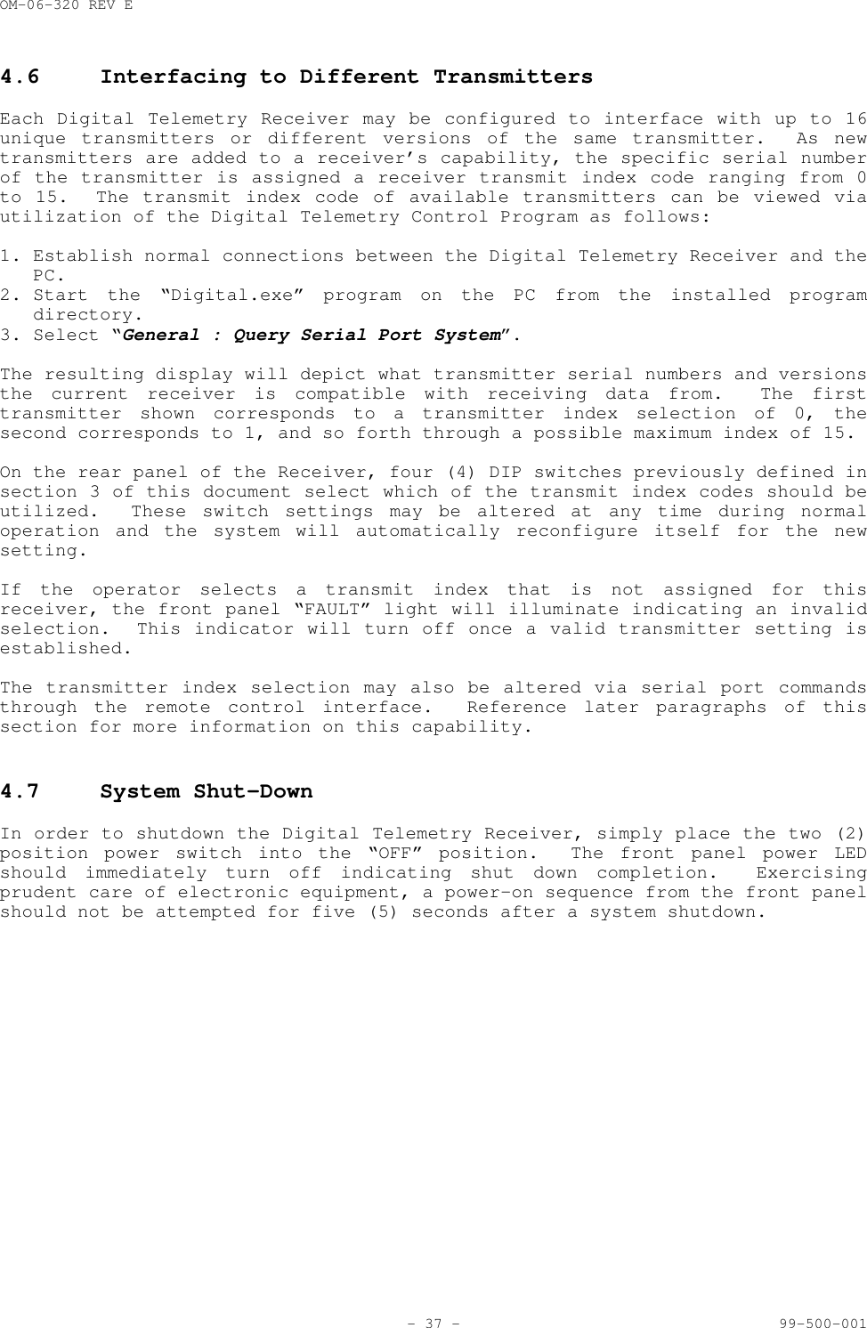
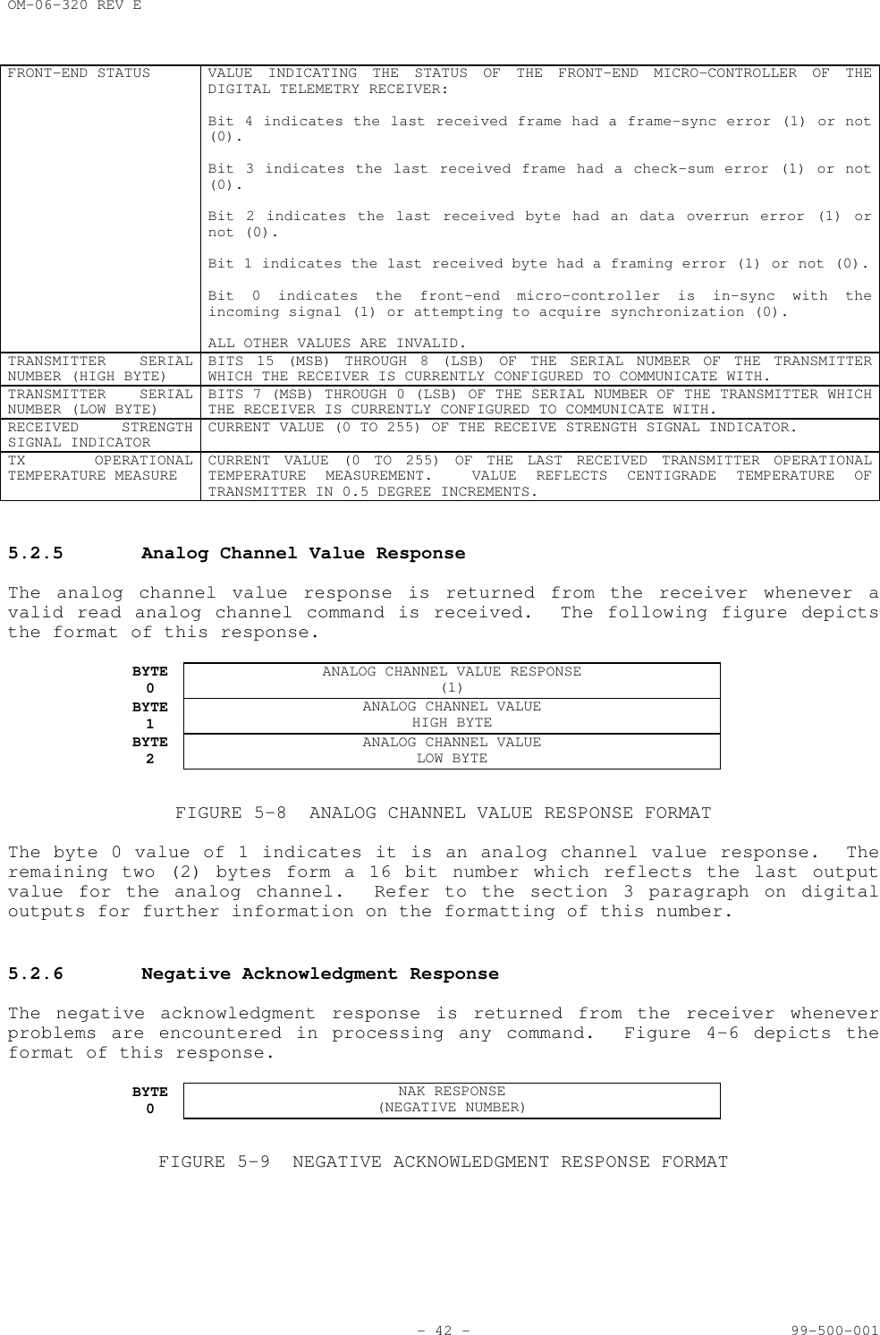
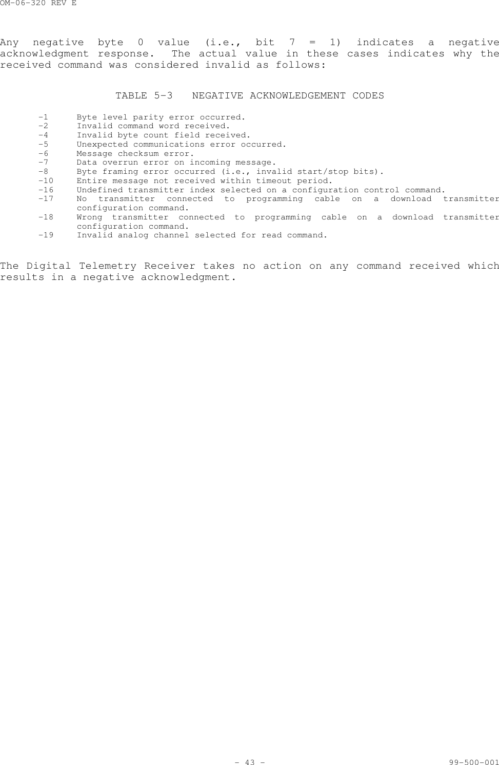
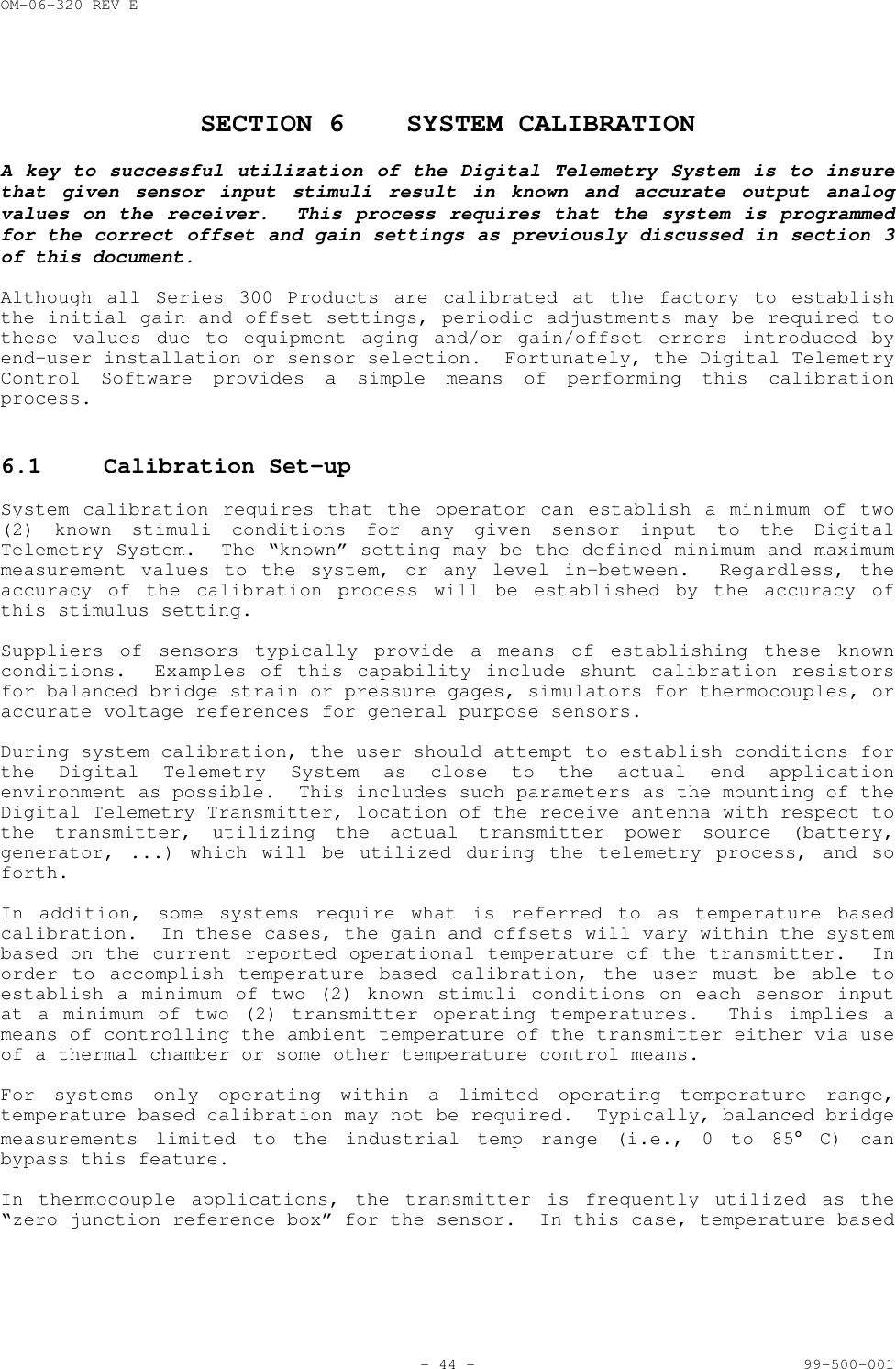
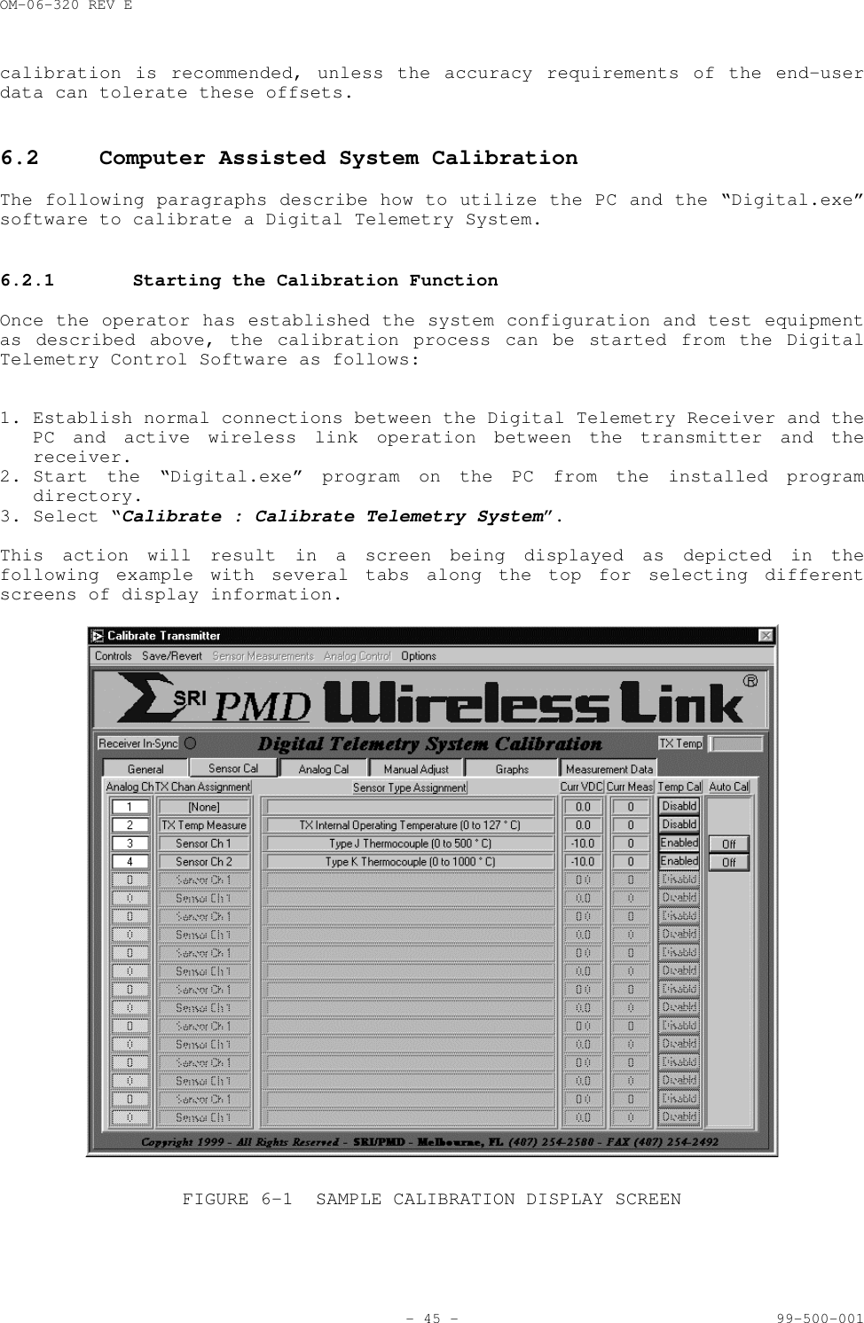
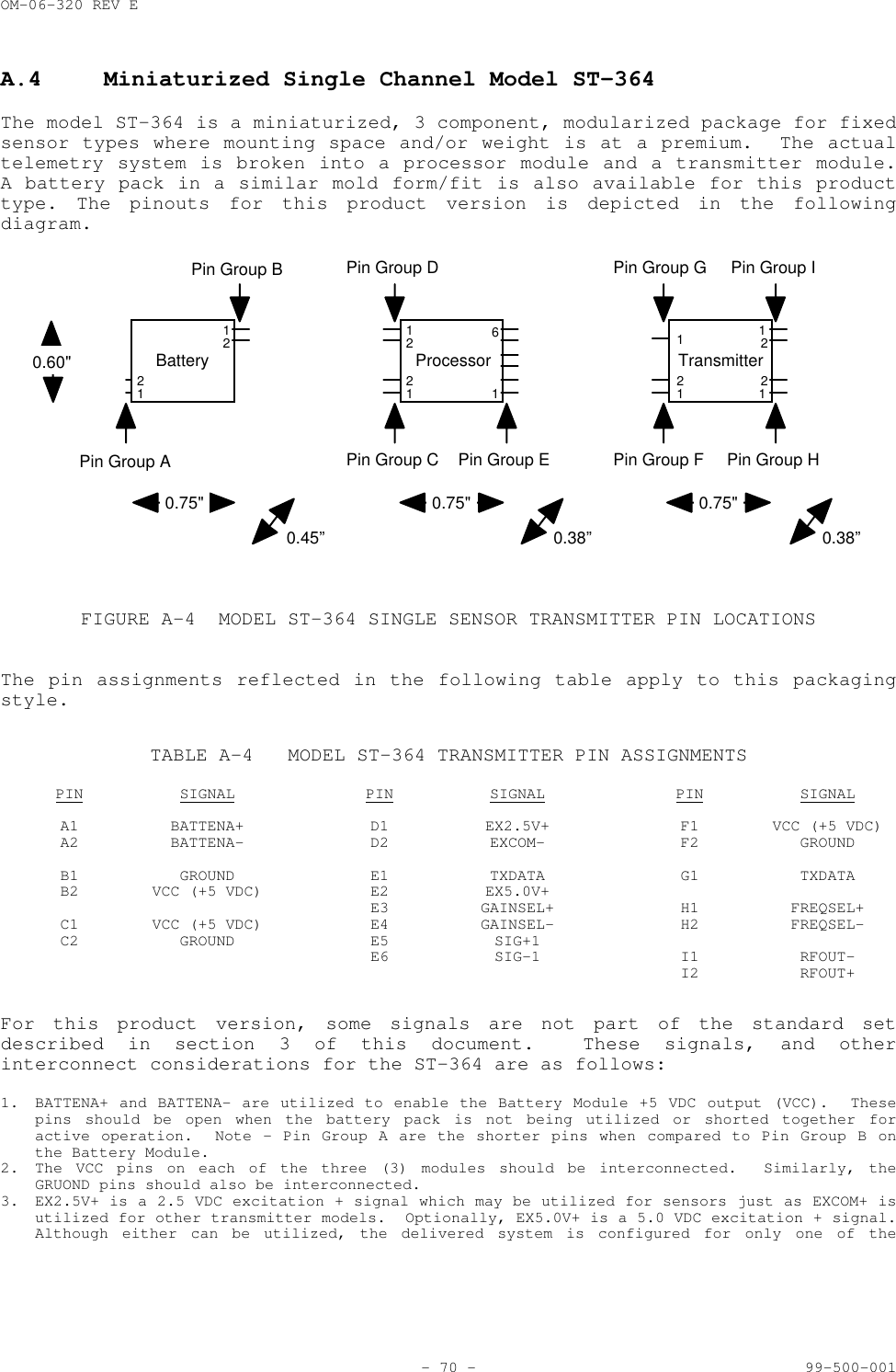
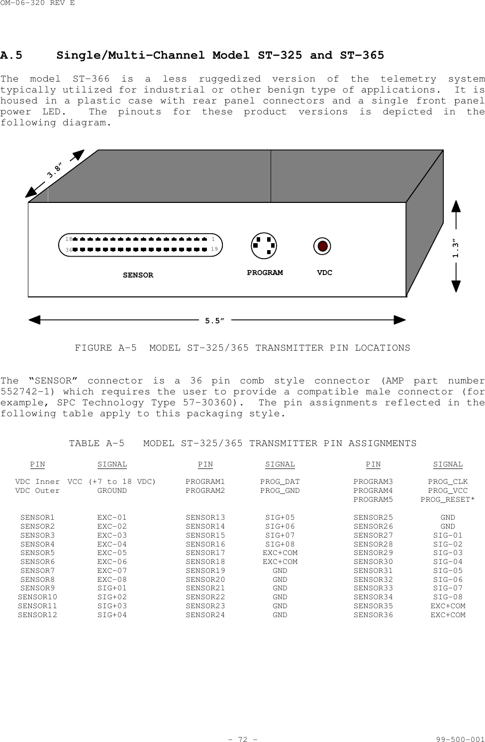
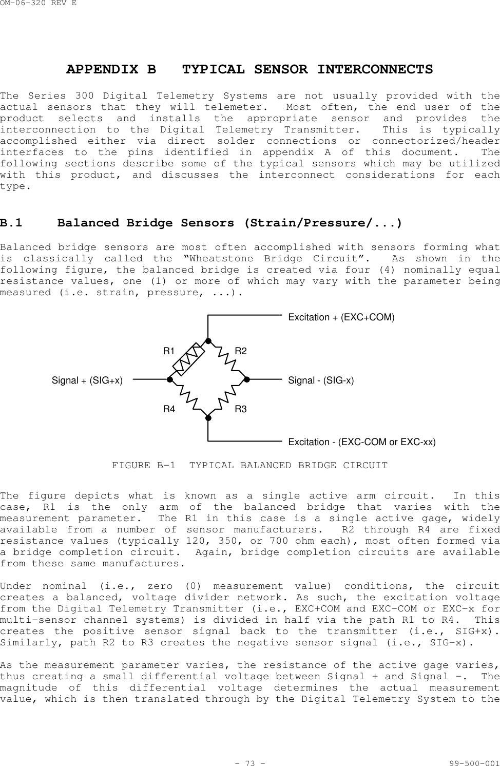
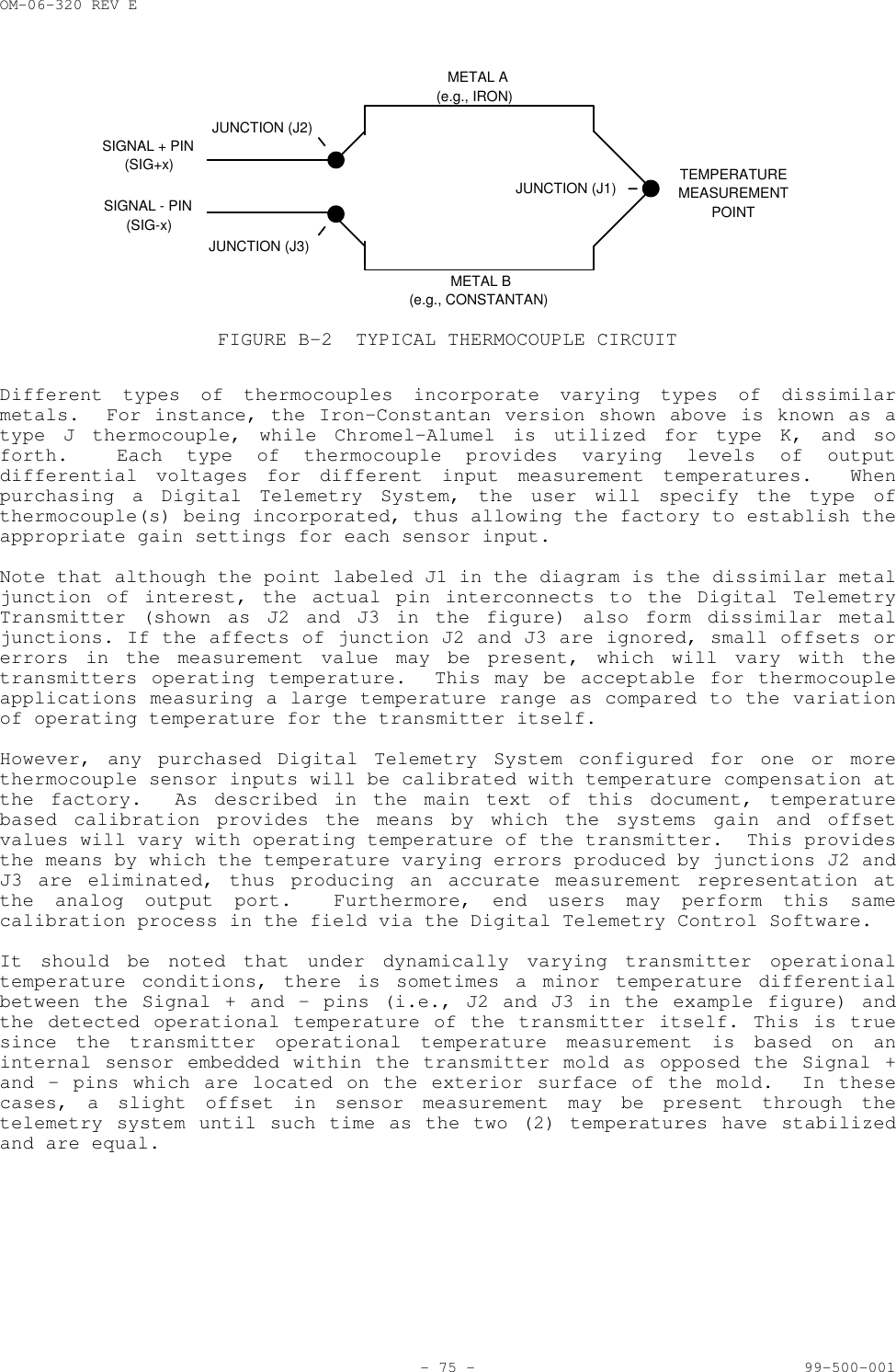
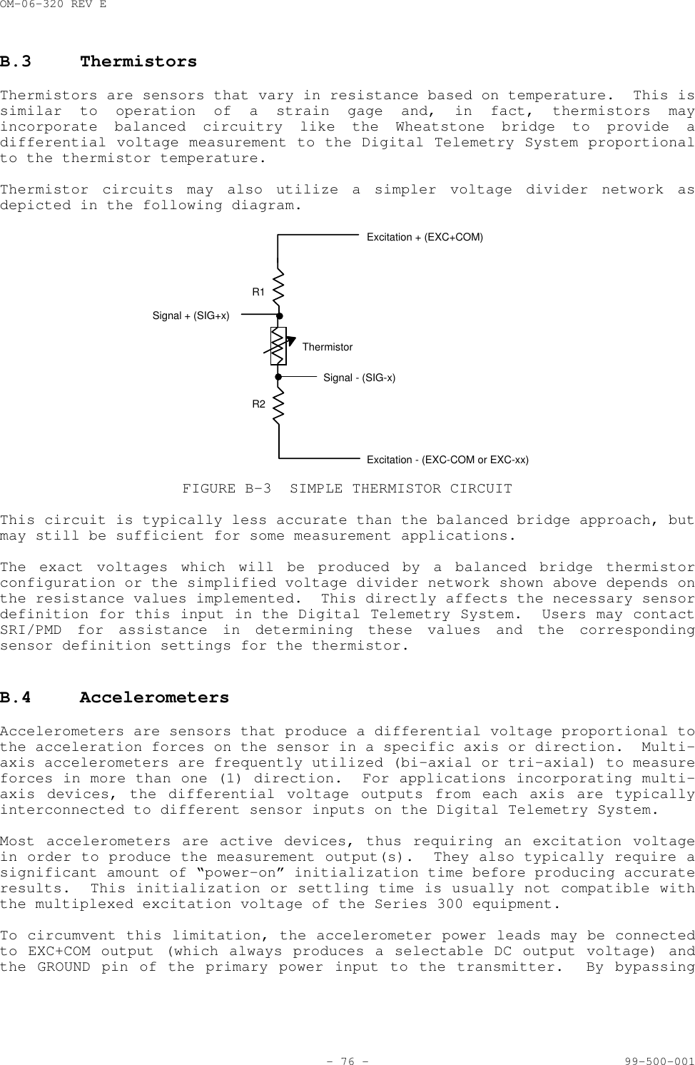
O and M Manual for Series 300 Equipment including ST326 and SR346

OM-06-320 REV E- i - 99-500-001SRI/PMD SERIES 300 DIGITAL TELEMETRY SYSTEMSA BRIEF INTRODUCTIONWith over 25 years of experience in the field of industrial and commercial telemetry systems,SRI/PMD stands as an industry leader in providing an efficient means of transporting measurementdata from one location to another.  The use of Wireless Link technology allows these systems tobe utilized to obtain information from hard to get to locations, or from places where it issimply inconvenient and/or insecure to run hard wired interconnects.With the advent of our newest Series 300 Digital Telemetry Systems, we have released the power ofDigital Signal Processing into what was previously a purely “analog” marketplace.  The use of alldigital signal processing not only furnishes a more robust and versatile means of gathering,transmitting, processing, and outputting highly accurate measurement data, but it also providesthis capability at a cost affordable for even budget conscientious consumers.In developing the Series 300 systems, SRI/PMD has taken technology developed for highly criticalspace telemetry applications and applied it to designs suited for a wide variety of applicationshere on earth.  Whether your particular need is gathering real-time torque, pressure, ortemperature data from large industrial equipment, or is more simply oriented toward sending abasic analog signal across a parking lot, we believe you will find the right solution to yourrequirements at a price far below what has previously been offered.LIMITED WARRANTYSRI/PMD warrants that the receiver and accessory equipment’s of its manufacture as identifiedwithin this document shall, at the time of shipment to the original purchaser, be free fromdefects in material and workmanship and conform to the specifications at time of purchase(incorporated herein) for a period of one (1) year from the date of original shipment.Encapsulated transmitters and batteries shall be covered under these same warranty terms for aperiod of 90 days from the date of original shipment.This warranty applies only to equipment installed, operated, and maintained in accordance withSRI/PMD recommendations, and such warranty does not apply where SRI/PMD determines that anyclaimed defect has been caused by installation or repair, alteration, accident, or excessivedeterioration due to environmental contamination.SRI/PMD’s obligation under this warranty is limited to repairing, or replacing, exclusive of costof installation and labor charges, any part that SRI/PMD determines to be defective, providedthat such part is received at SRI’s principal office, freight prepaid.  All equipment's mustreceive prior approval for return to SRI for warranty repair, and must be sent prepaid.  If theyare returned collect, they will not be accepted.This warranty is subject to any existing conditions of supply which may directly affect SRI/PMD’sability to obtain materials or manufacture replacement parts.SRI/PMD makes no warranty that the equipment shall be merchantable or fit for any particularpurpose; nor does SRI make other warranties, express or implied, by operation of law orotherwise, except such as are expressly set forth herein.  SRI/PMD shall not be liable to buyer,or to any third persons for any incidental, consequential, special or contingent damages forbreach of any warranty.IMPORTANT NOTICEMost Series 300 products are designed as component devices that require external components tofunction.  The products are intended to allow for full Part 15 compliance; however, they are notapproved by the FCC or any other agency worldwide.  The purchaser understands that approvals maybe required prior to the sale or operation of this device, and agrees to utilize the component inkeeping with all laws governing its operation in the country of operation.Some specific Series 300 models have been fully certified for FCC part 15 unlicensed operation.Contact SRI/PMD for further information for these units.
OM-06-320 REV E- ii - 99-500-001LIST OF EFFECTIVE PAGESDates of issue for original and changed pages are:Revision - August 1998Revision A February 1999Revision B May 1999Revision C June 1999Revision D November 1999Total number of pages in this publication is 85 consisting of the following:i - viii Table of Contents/List of Figures/List of Tables1 - 77 Document Main TextNOTE: On partial document updates, insert latest changed pages and destroysuperseded pages.  A vertical line in the outer margin of the page indicatesthe portion of the text affected by changes.  A vertical line in the outermargin of the Figure or Table name indicates changes to illustrations ortables.RECORD OF CHANGESREVISION DATE TITLE OR BRIEF DESCRIPTIONN/A March 1998 Draft Market Research ReleaseBreadboard Version 0.00- August 1998 ST-320/SR-340 Beta Test ReleaseFW Versions 1.00A February1999 Production Upgrade Release – ST-360/SR-380FW Versions 2.00B May1999 Firmware Upgrade and Pinout CorrectionsFW Versions 2.01C June1999 Upgrade to All FirmwareFW Versions 2.05D November1999 Production Release for Software 3.00Including Extended SW Capabilities
OM-06-320 REV ETABLE OF CONTENTS- iii - 99-500-001SECTION 1 INTRODUCTION ..................................... 11.1 Scope ............................................................ 11.2 Product Overview ................................................. 11.3 Product Description .............................................. 21.4 Model Numbers .................................................... 31.5 Technical Specifications ......................................... 41.5.1 Transmitter Specifications .................................... 51.5.2 Receiver Specifications ....................................... 51.5.3 Optional Accessory Equipment and Software ..................... 6SECTION 2 DIGITAL TELEMETRY SYSTEM DESCRIPTION ............. 82.1 Transmitter Details .............................................. 82.2 Receiver Details ................................................. 92.3 System Data Processing Overview ................................. 102.3.1 Gain and Offset Processing ................................... 112.3.2 Data Filtering ............................................... 142.4 Digital Telemetry Control Software .............................. 142.4.1 Serial Numbers and Versions .................................. 152.4.2 File Structure ............................................... 152.5 Configurable System Parameters and Processing ................... 16SECTION 3 RECEIVING, INSPECTION AND INSTALLATION .......... 183.1 Unloading and Unpacking ......................................... 183.2 Receiving Documentation ......................................... 183.3 Installation and Connection Requirements ........................ 183.4 Transmitter Signal Definitions and Characteristics .............. 193.5 Receiver Indicators, Controls, and Connector Interfaces ......... 203.5.1 Antenna Input ................................................ 203.5.2 VDC Input .................................................... 203.5.3 Remote Status/Control ........................................ 203.5.4 Digital Telemetry Transmitter Programming Interface .......... 213.5.5 DIP Switch Control ........................................... 213.5.6 Digital Output ............................................... 233.5.7 Analog Outputs ............................................... 253.5.8 Channel 1 Analog ............................................. 26
OM-06-320 REV ETABLE OF CONTENTS (CONTINUED)- iv - 99-500-0013.5.9 Channel 2 Analog ............................................. 263.5.10 Power On/Off Switch .......................................... 263.5.11 Front Panel LED Indicators ................................... 27SECTION 4 BASIC OPERATION ................................. 284.1 Getting Started ................................................. 284.2 Stand-alone Validation of the Digital Telemetry System .......... 304.3 Establishing Wireless Link Communications Settings .............. 324.3.1 Scanning the Available Communications Channels ............... 324.3.2 Monitoring Online Communications Performance ................. 334.3.3 Changing the Communications Settings ......................... 334.4 Loading/Restoring Configuration Tables/Software ................. 354.5 Changing Transmitter Versions ................................... 364.6 Interfacing to Different Transmitters ........................... 374.7 System Shut-Down ................................................ 37SECTION 5 REMOTE STATUS/CONTROL ........................... 385.1 Remote Interface Frame Format ................................... 385.2 Data Field Contents ............................................. 395.2.1 Set Configuration Command .................................... 395.2.2 Report Status Command ........................................ 405.2.3 Read Analog Channel Command .................................. 405.2.4 System Status Response ....................................... 415.2.5 Analog Channel Value Response ................................ 425.2.6 Negative Acknowledgment Response ............................. 42SECTION 6 SYSTEM CALIBRATION .............................. 446.1 Calibration Set-up .............................................. 446.2 Computer Assisted System Calibration ............................ 456.2.1 Starting the Calibration Function ............................ 456.2.2 Calibrating Sensor Channels .................................. 466.3 Manual Adjustments to Calibration Data .......................... 496.4 Analog Channel Calibration ...................................... 49SECTION 7 DIGITAL TELEMETRY SYSTEM DEFINITIONS ............ 517.1 Viewing System Definitions ...................................... 51
OM-06-320 REV ETABLE OF CONTENTS (CONTINUED)- v - 99-500-0017.1.1 “System” Display ............................................. 527.1.2 “TX General” Display ......................................... 537.1.3 “Sensor Channels” Display .................................... 537.1.3.1 Sampling Dwell Control ................................... 547.1.3.2 Sensor Definitions ....................................... 547.1.3.2.1 Generic Analog Voltages .............................. 557.1.3.2.2 Strain Gages ......................................... 557.1.3.2.3 Thermocouple’s ....................................... 567.1.3.2.4 Pressure Transducers ................................. 567.1.3.2.5 Accelerometers ....................................... 567.1.3.2.6 Thermistors .......................................... 577.1.4 “Analog Channels” Display .................................... 577.1.5 “Operational Parameters” Display ............................. 587.1.5.1 Transmitter Parameters ................................... 587.1.5.2 Receiver Parameters ...................................... 587.1.5.2.1 Asynchronous Operation ............................... 597.1.5.2.2 Synchronous Operation ................................ 597.2 Changing System Definitions ..................................... 607.2.1 Transmitter Definition Control ............................... 607.2.2 Editing Parameters ........................................... 617.2.3 Saving Updates ............................................... 627.3 Printing System Reports ......................................... 63SECTION 8 MAINTENANCE ..................................... 648.1 Maintenance Concept ............................................. 648.2 Preventive Maintenance Requirements ............................. 648.2.1 Inspection ................................................... 648.2.2 Cleaning ..................................................... 658.3 Corrective Maintenance Requirements ............................. 65APPENDIX A MODEL DEPENDENT PIN ASSIGNMENTS............... 66A.1 Single Channel Model ST-321, ST-325, and ST-361 ................. 67A.2 Multi-Channel Model ST-321, ST-325 or ST-361 .................... 68A.3 Piston Mount Multi-Channel Model ST-363 ......................... 69A.4 Miniaturized Single Channel Model ST-364 ........................ 70A.5 Single/Multi-Channel Model ST-326 and ST-366 .................... 72APPENDIX B TYPICAL SENSOR INTERCONNECTS.................. 73B.1 Balanced Bridge Sensors (Strain/Pressure/...) ................... 73B.2 Thermocouples ................................................... 74
OM-06-320 REV ETABLE OF CONTENTS (CONTINUED)- vi - 99-500-001B.3 Thermistors ..................................................... 76B.4 Accelerometers .................................................. 76B.5 Other Sensor Types .............................................. 77
OM-06-320 REV ELIST OF FIGURES- vii - 99-500-001FIGURE 1-1 SRI/PMD WIRELESS LINK PRODUCT.............................. 1FIGURE 1-2 SYSTEM OVERVIEW............................................. 2FIGURE 2-1 TRANSMITTER BLOCK DIAGRAM................................... 8FIGURE 2-2 RECEIVER BLOCK DIAGRAM...................................... 9FIGURE 2-3 DATA PROCESSING OVERVIEW................................... 11FIGURE 2-4 DATA PROCESSING DETAILS.................................... 12FIGURE 3-1 REMOTE STATUS/CONTROL INTERFACE CONNECTOR.................. 21FIGURE 3-2 DIP SWITCH CONTROL INTERFACE............................... 22FIGURE 3-3 DIGITAL OUTPUT CONNECTOR................................... 23FIGURE 3-4 DIGITAL OUTPUT TIMING DIAGRAM.............................. 24FIGURE 3-5 ANALOG OUTPUT CONNECTOR.................................... 25FIGURE 4-1 DIGITAL CONTROL PROGRAM START-UP SCREEN.................... 29FIGURE 5-1 REMOTE STATUS/CONTROL BYTE FORMAT.......................... 38FIGURE 5-2 REMOTE STATUS/CONTROL FRAME FORMAT......................... 38FIGURE 5-3 SET CONFIGURATION COMMAND FORMAT........................... 39FIGURE 5-4 REPORT STATUS COMMAND FORMAT............................... 40FIGURE 5-6 READ ANALOG CHANNEL COMMAND FORMAT......................... 40FIGURE 5-7 STATUS RESPONSE FORMAT..................................... 41FIGURE 5-8 ANALOG CHANNEL VALUE RESPONSE FORMAT....................... 42FIGURE 5-9 NEGATIVE ACKNOWLEDGMENT RESPONSE FORMAT.................... 42FIGURE 6-1 SAMPLE CALIBRATION DISPLAY SCREEN.......................... 45FIGURE 7-1 SAMPLE CONFIGURATION DISPLAY SCREEN........................ 52FIGURE A-1 MODEL ST-321/326/361 SINGLE SENSOR TX PIN LOCATIONS........ 67FIGURE A-2 MODEL ST-321/326/361 MULTI-SENSOR TX PIN LOCATIONS......... 68FIGURE A-3 MODEL ST-363 MULTI-SENSOR TRANSMITTER PIN LOCATIONS........ 69FIGURE A-4 MODEL ST-364 SINGLE SENSOR TRANSMITTER PIN LOCATIONS....... 70FIGURE A-5 MODEL ST-325/365 TRANSMITTER PIN LOCATIONS................. 72FIGURE B-1 TYPICAL BALANCED BRIDGE CIRCUIT............................ 73FIGURE B-2 TYPICAL THERMOCOUPLE CIRCUIT............................... 75FIGURE B-3 SIMPLE THERMISTOR CIRCUIT.................................. 76
OM-06-320 REV ELIST OF TABLES- viii - 99-500-001TABLE 1-1 SERIES 300 MODEL DESCRIPTIONS............................... 4TABLE 1-2 TRANSMITTER SPECIFICATIONS.................................. 5TABLE 1-3 RECEIVER SPECIFICATIONS..................................... 6TABLE 1-4 OPTIONAL SUPPORT EQUIPMENT.................................. 6TABLE 2-1 SAMPLE DATA PROCESSING STAGES.............................. 13TABLE 2-2 SELECTABLE CONFIGURATION AND PROCESSING OPTIONS............ 16TABLE 3-1 TRANSMITTER SIGNAL DEFINITIONS, AND CHARACTERISTICS........ 19TABLE 3-2 RF INPUT CHARACTERISTICS................................... 20TABLE 3-3 INPUT POWER CHARACTERISTICS................................ 20TABLE 3-4 REMOTE STATUS/CONTROL PIN ASSIGNMENTS...................... 21TABLE 3-5 PROGRAMMING INTERFACE PIN ASSIGNMENTS...................... 21TABLE 3-6 DIP SWITCH ASSIGNMENTS..................................... 22TABLE 3-7 DIP SWITCH SELECTIONS...................................... 22TABLE 3-8 DIGITAL OUTPUT SIGNAL CHARACTERISTICS...................... 23TABLE 3-9 DIGITAL OUTPUT PIN ASSIGNMENTS............................. 23TABLE 3-10 ANALOG CHANNEL TO DIGITAL ADDRESS CORRELATION.............. 24TABLE 3-11 DIGITAL OUTPUT RANGES...................................... 25TABLE 3-12 ANALOG OUTPUT SIGNAL CHARACTERISTICS....................... 25TABLE 3-13 ANALOG OUTPUT PIN ASSIGNMENTS.............................. 26TABLE 3-14 ANALOG CHANNEL 1/2 SIGNAL CHARACTERISTICS.................. 26TABLE 3-15 LED INDICATOR DESCRIPTIONS................................. 27TABLE 4-1 EXPECTED BOOT-UP ASCII TEXT................................ 30TABLE 4-2 SELF-TEST FAILURE CODES.................................... 30TABLE 5-1 SET CONFIGURATION COMMAND PARAMETERS....................... 40TABLE 5-2 STATUS RESPONSE PARAMETERS................................. 41TABLE 5-3 NEGATIVE ACKNOWLEDGEMENT CODES............................. 43TABLE A-1 MODEL ST-321/ST-326/ST-361 SINGLE CHANNEL TX PIN ASSIGNMENTS67TABLE A-2 MODEL ST-321/ST-326/ST-361 MULTI-CHANNEL TX PIN ASSIGNMENTS 68TABLE A-3 MODEL ST-363 TRANSMITTER PIN ASSIGNMENTS................... 69TABLE A-4 MODEL ST-364 TRANSMITTER PIN ASSIGNMENTS................... 70TABLE A-5 MODEL ST-325/365 TRANSMITTER PIN ASSIGNMENTS............... 72
OM-06-320 REV E- 1 - 99-500-001SECTION 1 INTRODUCTIONThe Series 300 Digital Telemetry Equipment represents thenext generation of SRI/PMD’s Wireless Link products.  Dueto a unique mixture of high technology RF, analog anddigital circuitry, a highly versatile measurementcapability is provided in a variety of compact packagesfully supporting applications requiring low powerconsumption and high reliability while still being offeredat an affordable price.Supporting anywherefrom 1 to 16 sensorchannel inputs, allSeries 300 productsprovide both highlyaccurate analog andhigh-speed digitalmeasurement outputs.FIGURE 1-1 SRI/PMD WIRELESS LINK PRODUCT1.1 ScopeThis manual describes the SRI/PMD Series 300 Digital Telemetry Product Line,including both transmit and receive processing units.  The manual includesspecifications, design description, installation, and operation instructionsalong with routine maintenance requirements for these products.1.2 Product OverviewSRI/PMD (formerly known as Physical Measurement Devices or simply PMD) hasbeen designing and producing ruggedized wireless telemetry systems for inexcess of 25 years.  An old slogan in the instrumentation community statesthat "Measurement is the beginning of knowledge".  Previous versions of PMD'sWireless Link product have assisted customers in gaining insight intooperational parameters which were, at best, difficult to acquire with anyamount of reliability or longevity, if not totally unobtainable.With the advent of the new, fully digital, SRI/PMD Wireless Link products,potential users are being offered an improved solution that not only providesbetter technology for existing customers and applications, but alsosignificantly expands the possible uses of these designs.  By offering:• lower cost, • improved  measurement accuracy,• true "hands-off" operation, and• more robust and user selectable wireless communications methods,these products offer a cost effective and timely solution to a multitude ofhere-to-fore "hard-wired" applications.
OM-06-320 REV E- 2 - 99-500-001In a nutshell, telemetry can encompass the entire process by which ameasurement value is obtained, possibly quantified, qualified, or processed inother ways, and then transmitted via some mechanism to the "end user" forfinal processing or response actions.  The "end user" in this case may be ahuman for manual interpretation and analysis or, more often, a machine forautomated processing functions. The phrase "Digital Telemetry" simplyspecifies that the methodology utilized to obtain, process, and transmit themeasurement data incorporates digital techniques, a highly efficient and morereliable means of handling data processing and transmission.Typical measurements which telemetry can provide access to include:temperature, speed, direction, motion,location, distance, displacement, strain,torque, energy, power, pressure,humidity, density, ...Furthermore, many applications require access to multiple and/or a variety ofthese measurements at the same time to allow for meaningful interpretation ofthe data.  One of the significant benefits of digital telemetry is that it canbe easily and readily customized to the end user requirements, allowingvarious measurement (or sensor) inputs to be sampled nearly simultaneously,cross correlated if need be, and presented as parallel analog or digitaloutputs to the end user.  For certain implementations, the sampling andcorrelation algorithms can be configured in real-time, providing for adaptivemeasurement and response requirements.1.3 Product DescriptionThe series 300 products are available in a variety of design options.  The ST-320/SR-340 versions of products provide digital telemetry capability operatingin the versatile 902 to 928 MHz ISM frequency band while the ST-360/SR-380versions operate in the classic 88 to 108 MHz FM frequency bands.  Based onthe exact end-user requirements, an optimized product choice can be found toprovide extremely robust wireless communications, even in indoor environmentswhere building structures may obstruct a direct line-of-site transmission orin contaminated environments such as inside engine compartments.The following diagram presents a simplified overview of the latest generationSRI/PMD Wireless Link system....Sensor InputsfromUser Platform(up to 16)ExcitationVoltages ...DigitalTelemetryTransmitterVDCWireless Link DigitalTelemetryReceiverOptionalPersonalComputerwithSupportSoftware,ExtendedSoftware,and/orSampleDisplaySoftwareStandard SerialInterfaceOffline ProgrammingInterface...AnalogOutputs(up to 18)Digital OutputsFIGURE 1-2 SYSTEM OVERVIEW
OM-06-320 REV E- 3 - 99-500-001As shown, the system consists of the following major elements:1)  The Digital Telemetry Transmitter is a miniaturized and ruggedized radiofrequency (RF) transmitter providing the interface circuitry to selectand sample up to 16 sensor inputs and transmit the detected readings indigital format over the Wireless Link.2)  The Digital Telemetry Receiver provides the logic to recover thetransmitted data, detect and account for errors which might have beenintroduced via the transmission path, and output error free anddigitally compensated samples of the sensor data in both analog anddigital output formats.  The receive system also supports an optionalinterface to a standard personal computer for status, control, andanalysis functions.3)  The optional Personal Computer can be utilized to execute additionalsoftware packages available from SRI/PMD.  These optional supportsoftware packages include:a) Standard support software for monitoring general systemhealth, communications performance, and sensor gain/offsetcalibration functions.b) Extended support software providing for editing of sensordefinitions including type, sampling frequency, filtering,measurement ranges, and so forth.c) Display capture/display software for storing measurementdata to the PC disk or displaying the data ingraphical/scope type formats.The transmitter portion of the series is available in a variety of shapes andsizes depending on the exact end user requirements.  This includesminiaturized, single channel versions, or versatile, multi-channel, mixedsensor type packages.  The design also readily supports custom packaging forunique end user applications.The receiver is offered as both a stand-alone desk or bench top enclosureconfiguration or as a 19” rack mountable chassis.The communications link for the telemetry transmission is supported in eitherthe popular 900 MHz ISM band or the classic 90 MHz FM band.  Depending uponthe exact application, an ideal solution is available to provide a robust andreliable communications path.1.4 Model NumbersEach version of the Series 300 products assigned a model number.  Transmittersfor this series are always designated as an ST-3xx where xx defines the exactmodel type.  Similarly, receivers are designated as an SR-3xx.  The followingtable provides an overview of each of the available standard models for thisseries.
OM-06-320 REV E- 4 - 99-500-001TABLE 1-1 SERIES 300 MODEL DESCRIPTIONSModelNumber DescriptionST-321 A 900 MHz Wireless Link Transmitter housed in a 1.75” diameter, <1” tall disk shaped epoxy compound mold.  Intended for severeenvironment applications.  Available in 1 to 16 sensor inputchannel versions.ST-325 A 900 MHz Wireless Link Transmitter housed in a 1.3” x 3.8” by5.6” plastic casing.  Intended for non-shock, industrial typeapplications.  Available in 1 to 8 sensor input channel versions.ST-326 Same product and versions as the ST-321 but fully tested andcertified for FCC part 15 unlicensed operation.ST-361 A 90 MHz Wireless Link Transmitter housed in a 1.75” diameter, <1”tall disk shaped epoxy compound mold. Intended for severeenvironment applications.  Available in 1 to 16 sensor inputchannel versions.ST-363 A 90 MHz Wireless Link Transmitter housed in a 1.2” x 3.6” x 0.65”moon shaped epoxy compound mold.  Intended for automotive pistonmount applications.  Available in 1 to 16 sensor input channelversions.ST-364 A 90 MHz Wireless Link Transmitter housed as 2 individual 0.75” x0.6” x 0.4” packages.  Intended for miniaturized, severeenvironment applications.  Limited to fixed frequency and singlesensor input channel version.ST-366 A 90 MHz Wireless Link Transmitter housed in a 1.3” x 3.8” by 5.6”plastic casing.  Intended for non-shock, industrial typeapplications.  Available in 1 to 8 sensor input channel versions.SR-341 Benchtop receiver compatible with any model ST-32x transmittermodel.  Available in 1 to 18 output channel versions.SR-342 19” rack mount receiver compatible with any model ST-32xtransmitter model.  Available in 1 to 18 output channel versions.SR-381 Benchtop receiver compatible with any model ST-36x transmittermodel.  Available in 1 to 18 output channel versions.SR-382 19” rack mount receiver compatible with any model ST-36xtransmitter model.  Available in 1 to 18 output channel versions.1.5 Technical SpecificationsA summary of the technical specifications and characteristics of thereferenced telemetry equipment is presented in the paragraphs that follow.
OM-06-320 REV E- 5 - 99-500-0011.5.1 Transmitter SpecificationsThe specifications indicated in the following table apply to the DigitalTelemetry Transmitter.TABLE 1-2 TRANSMITTER SPECIFICATIONSPARAMETER SPECIFICATIONOUTPUT FREQUENCIES 8 Channels from 902 to 928 MHz (Series ST-320)88 to 108 MHz in 200 KHz Channels (Series ST-360)MODULATION FORMATS Minimum Shift Keyed (MSK) -or-Standard Frequency Shift Keyed (FSK)NUMBER OF SENSOR INPUTS  Up to 16INPUT SENSOR LEVEL RANGE Programmable within the range of 0.625 uVDC to 5 VDC.SENSOR EXCITATION Optional sensor excitation voltage driven duringsensor sampling period.  Excitation voltage isselectable from 0.625 to 5 VDC.TYPICAL SENSOR TYPES Absolute voltage measurements, such as Type J/KThermocouples (up to 1000° measurement range),Displacement Sensors, Generic Analog Voltages, ...Relative voltage measurements, such as Strain Bridges(120, 350 ohm, or 700 ohm, 4 arms, up to +/- 2000uStrain measurement range), Pressure Transducers, ...CustomMEASUREMENT RESOLUTION 8 bitsSAMPLING RATE Up to 3 K samples per second (Series ST-320)Up to 27 K samples per second (Series ST-360)SENSOR MULTIPLEXING OPTIONS High speed sequential, or optional dwell/stepoperationCustomINPUT POWER +7 Vdc to +18 VdcCustomPOWER CONSUMPTION < 20 mA (excluding sensor loads on excitation outputs)OPERATING TEMPERATURE Standard - 0 to +70° CIndustrial - 0 to +85° CAutomotive – 0 to +125° C (ST-360 only)ACCELERATION 5,000 G Rotational Typical1.5.2 Receiver SpecificationsThe specifications indicated in the following table apply to the DigitalTelemetry Receiver.
OM-06-320 REV E- 6 - 99-500-001TABLE 1-3 RECEIVER SPECIFICATIONSPARAMETER SPECIFICATIONRECEIVE/DEMODULATION CAPABILITIES Compatible with transmitter waveformNUMBER OF ANALOG OUTPUTS  Up to 18SENSOR TO ANALOG CHANNEL ASSIGNMENTS SelectableANALOG OUTPUT RANGES 2 Channels fixed at 0 to 5 VdcAdditional channels selectable from 0 to 5Vdc, +/- 5 Vdc, 0 to 10 Vdc or +/- 10 VdcANALOG OUTPUT RESOLUTION 2 Channels fixed at 8 bitsAdditional channels 12 bitsDIGITAL OUTPUT 16 bits of parallel digital samples6 bit channel indicatorData StrobeSample Error IndicatorERROR DETECTION Data checksum capable of detecting errorrates of up to 1 in 100SENSOR DATA COMPENSATION OPTIONS Fixed gain/offset compensationTX operational temp dependent compensationCustomDATA PROCESSING OPTIONS NoneInfinite Impulse Response Averaging    (K = ½, ¼, or 1/8)CustomINPUT POWER +12 Vdc (AC/DC Wall Plug Standard)POWER CONSUMPTION < 12 Watt typicalPACKAGING OPTIONS 9” x 7” x 3” Bench Top Enclosure1U 19” Rack MountCustomOPERATING TEMPERATURE Standard - 0 to +70° CIndustrial - 0 to +85° C1.5.3 Optional Accessory Equipment and SoftwareIn addition to the standard Digital Telemetry Equipment listed above, thefollowing optional support equipment is also supported.TABLE 1-4 OPTIONAL SUPPORT EQUIPMENTDESCRIPTIONAntenna’s for the Digital Telemetry Receiver.  Typically available in ¼ or ½ wavelength versionsfor either direct mounting onto the enclosure, as a stand-alone bench/desktop standing unit, oras a magnet mounted unit.Batteries for operating the Digital Telemetry Transmitter, available in rechargeable ordisposable versions.Inductively coupled power generator modules for shaft or piston mount applications.  Generatesthe 7 Vdc power required by the Digital Telemetry Transmitter for these applications.
OM-06-320 REV E- 7 - 99-500-001Software for a standard Personal Computer.  May include the following packages:Standard Software Package (included with all systems):Basic system support functions including query telemetry system, monitor self-testresults, print a detailed system configuration report, ...Link analysis functions for the Digital Telemetry System.  Provides a means to analyzeall potential communications links for the system to select the optimum channel.  Alsoprovides error rate analysis capabilities to determine expected link performancecharacteristics as well as online monitoring features of an active systemstransmission characteristics.Calibration control functions for the Digital Telemetry System.  Provides a means fora user to alter the compensation and calibration data associated with a transmitterbased on actual sensor or other types of measurement errors.Extended Software Package:Configuration control functions for the Digital Telemetry System.  Allows a user toreassign sensor and analog channels, reconfigure a transmitter for alternate sensortypes, alter the transmission bandwidth allocation of the Wireless Link, set filteringcontrols for individual channels, and so forth.Display Software Package:Sample capture/display functions for the Digital Telemetry System.  Provides real timecapture of data samples from the Digital Telemetry Receiver and displays the samplesin a scope like format on a PC while also supporting the means to save the samples todisk for later viewing or analysis by other programs.
OM-06-320 REV E- 8 - 99-500-001SECTION 2 DIGITAL TELEMETRY SYSTEM DESCRIPTIONSeries 300 Wireless Link Digital Telemetry Systems are accomplished with anoptimum mix of analog and digital circuitry in order to provide a low-cost,flexible system capable of handling a wide variety of telemetry requirements.Utilization of state-of-the-art design technology combined with a latestgeneration micro-controller allows the design to meet requirements of a highperformance, high reliability communications link for transferring measurementdata while still maintaining a highly cost-effective price.2.1 Transmitter DetailsFigure 2-1 presents a more detailed overview of a Digital TelemetryTransmitter.ChannelSelectGain andExcitationSelectAnalogInputUp to 16SensorInputsUp to 16ExcitationOutputsSingleSensorInputsSingleExcitationOutputsHardwareBuildOptionDigitalDataStreamChannelSelectWirelessLinkExternal Programming InterfaceAnalogInput 2MicroControllerTemperatureSensorOptionalMultiplexersSignalContioningConfig Datain EEPromFMTransmitterFIGURE 2-1 TRANSMITTER BLOCK DIAGRAMAt the heart of the transmitter design is a high-speed micro-controller withembedded analog to digital conversion capabilities.  For most series 300products, execution processing of the micro-controller is determined viaconfiguration data stored within electronically erasable programmable read-only-memory (EEProm).  The configuration tables contained within this memorydictates operational characteristics such as the number of input sensorchannels, the type of each input, the desired sampling sequence to be utilizedfor data transmission purposes, output RF frequency selection, and so forth.Since the EEProm memory space can be reprogrammed via the external programming
OM-06-320 REV E- 9 - 99-500-001interface to the Digital Telemetry Receiver, all significant operationalcharacteristics of the Transmitter can be readily modified, even for fieldedunits.  Certain single channel, miniaturized series 300 models (e.g., ST-364)do not support the transmitter EEProm memory space and are built with fixedgain and sampling characteristics.For transmitters limited to a single input sensor channel, onboard circuitryis available to process the input measurement data through signal conditioningcircuitry.  When the number of input sensor channels exceeds one (1), anoptional multiplexer card is provided.  This card includes a sixteen (16) toone (1) multiplexer to support connecting multiple sensor channels to thesingle input of the main board.  All sensor-input logic also includesassociated excitation voltage output circuitry that may be utilized to drivesensors requiring an input voltage, such as balanced bridges.Operation of the signal conditioning logic is controlled via the micro-controller to establish appropriate gain settings.  This powerful feature ofthe design allows the same circuitry to be reprogrammed to support a widevariety of potential input sensor types.  Furthermore, because the sensor typeinformation is also included in the EEProm configuration tables, thesesettings can be changed for various user requirements.Data transmission across the wireless link is accomplished with dual datachannels known as the primary and the background channels respectively.  Theprimary data channel is allocated in excess of 90% of the transmit bandwidthand typically includes the input sensor data measurement information.  Thebackground channel is relatively low rate and contains information requiredfor receive side frame synchronization and error detection.Another key feature to the design is that the background channel can also beutilized to transmit data pertaining to the current transmitter operationaltemperature.  For applications which require a high degree of data accuracy,this information may be utilized to support real-time temperature basedcompensation of sensor data samples through the receive chain.2.2 Receiver DetailsFigure 2-2 presents a more detailed overview of the Series 300 DigitalTelemetry Receiver’s.ChannelSelectUp to 16AnalogOutputsDigitalDataStreamWirelessLinkRemote  InterfaceConfigControlDigitalDataWordsProgramming Interfaceto TransmitterReceiveStrengthSignalIndicatorDigitalOutputs2 AnalogOutputsOptionalExtendedI/O’sFront PanelLED’sDIPSwitchesBack endMicro ControllerProg/ConfigEEPromOther ExtInterfacesRS-232InterfaceProgramInterfaceFMReceiverFront EndMicro ContOpt ExtAnalog ChanDigitalInterfaceOnboardAnalog ChanFIGURE 2-2 RECEIVER BLOCK DIAGRAM
OM-06-320 REV E- 10 - 99-500-001The receiver incorporates two (2) high-speed micro-controllers to provide forfull real time processing of incoming measurement samples.  The front-endmicro-controller interfaces with the Wireless Link receiver to recover bit,byte, word, and frame synchronization with the incoming data stream.  Theprocess of achieving this level of synchronization is known as the acquisitionprocess and is in-turn reflected on the front panel “SYNC” indicator.  Onceframe synchronization has been achieved, the “SYNC” indicator is illuminated.After proper acquisition, the front-end micro-controller begins sendingreceived data sensor samples to the back-end processor.  In parallel with thisprocess, the front-end performs error detection functions via embeddedchecksums within the incoming data.  All received data samples during a framedetected to have an error within it are flagged as error samples.The back-end micro-controller accepts the data samples and providesconfigurable data processing on the information prior to outputting the datato analog and digital output channels.  Data processing, in this case, mayinclude standard gain adjustment multiplication, offset addition, transmittertemperature dependent data compensation, as well as alternate data averagingand or filtering functions.Program execution of the back-end micro-controller is directed via code andconfiguration tables stored in EEProm memory space resident on the card.  Thecontents of this memory space can be loaded via the remote control RS-232interface to a standard personal computer.  This feature allows fieldedDigital Telemetry Receiver systems to be upgraded to new releases ofexecutable firmware, or modified to support new transmitters or alter theprocessing characteristics of existing transmitters.The minimum configuration of a Digital Telemetry Receiver supports two (2)analog output channels.  These onboard channels, designated as Analog Channel1 and 2, are limited to eight (8) bits of data resolution and support anoutput voltage range of 0 to 5 Vdc.  An optional extension card may be addedto support up to 16 additional analog output channels (designated as AnalogChannels 3 through 18).  These channels support 12 bits of data resolution andcan be programmed to cover an entire output voltage range of -10 to +10 Vdc.Furthermore, the optional extension card contains highly accurate voltagereference circuitry to guarantee the accuracy of the +/- 10 Vdc range tobetter than +/- 0.2 percent.2.3 System Data Processing OverviewThe Series 300 products can be configured to process input sensor measurementsanywhere within the range of 0 to 5 VDC.  Typically, instrumentation sensorsdo not utilize this entire measurement range.  For instance, a single activearm, 350 ohm strain gage with 5 V excitation will only produce a +/- 1.25millivolt DC (mVDC) signal for strain levels of +/- 500 micro-strain (uE).Obviously, these signal levels are not overly useful to most end-userprocessing equipment.To create a useful signal, the product line provides programmable gain,offset, and data filtering functions on the input sensor signals.  Thefollowing sections describe this processing in more detail.
OM-06-320 REV E- 11 - 99-500-0012.3.1 Gain and Offset ProcessingThe Digital Telemetry process applies various stages of gain to the inputsignal such that the configured measurement input levels of the sensor end upcorresponding to a specified output analog voltage range (e.g., -10 to +10VDC).  For the strain gage example, this implies a gain of x 8000 in order totranslate -1.25 mVDC to -10 VDC and +1.25 mVDC to +10 VDC.A gain of this magnitude is never 100% accurate.  Furthermore, small errorsintroduced by the exact mechanical installation of the sensor, grounddifferentials, cabling losses, or transmitter sensor input to digitalmeasurement processing circuitry end up causing additional errors.  Theseerrors are reflected as incorrect gain or variations in offset (i.e., where a0 reading does not correspond to a 0 output).In order to compensate for these factors, the Digital Telemetry Systemprovides programmable gain and offset control that are invoked at variousstages within the system.  The following figure provides a very simplisticoverview of this process.SensorInput SystemGain SystemOffset OutputValueVDC VoltageUnipolar Range limitedfrom 0 to +5 VDC orBipolar Range limitedfrom -2.5 to +2.5 VDC.Installation, connection,or sensor interfacecircuitry characteristicscontribute to gain andoffset errors.Multiplier ValueAccomplished viaProgrammable GainAmplification in DigitalTelemetry Transmittercombined with DigitalMultiplier in Receiver()Adder ValueAccomplished viaDigital Adder inReceiver (limited to-10.00 to +20.00).Analog or DigitalRepresentation ofOutput VDC VoltageProgrammable foroutput range from -10 to+10 VDC.FIGURE 2-3 DATA PROCESSING OVERVIEWThe system gain and offset values are set to not only translate the inputmeasurement signal range to the desired analog output voltage range, but canalso be utilized to account for the gain and offset errors discussed above.The following figure presents a more detailed view of the entire signalprocessing of the Digital Telemetry System.
OM-06-320 REV E- 12 - 99-500-001SensorInput with Gainand Offset ErrorsTransmitterUnipolar/BipolarSelectIndependentlyConfigured for eachSensor Channel viaTransmit EEProm Tablesfor centering Sensor -Input at 0 (Unipolar) or2.5 VDC (Bipolar).TransmitterGainAmplifierIndependentlyConfigured for eachSensor Channel viaTransmit EEProm Tablesfor x1 to x2500 gain.TransmitterAnalog to DigitalConversionConversion from Analog0 to +5 VDC Signal toDigital Value from 0x00to 0xFF.Differential Sensor +and Sensor - InputsWirelessLinkTransmitterWirelessLinkReceiverReceiverUnipolar/BipolarFloating Point ConvertConversion of Digital IntegerValues to Floating PointRepresentation where 0x00 goesto 0.0 (Unipolar) or -10.0(Bipolar) and 0xFF goes to +20.0(Unipolar) or +10.0 (Bipolar).ReceiverGainMultiplierMultiplication ofFloating PointMeasurement byConfigurable GainMultiplier (0.01 to 9.99).ReceiverOffsetAdderAddition ofFloating PointMeasurement toConfigurable OffsetAdder (-10.0 to +20.0).AnalogOutputChannelOutput of FloatingPoint Value asAnalog Level inRange of -10 to +10VDC.FIGURE 2-4 DATA PROCESSING DETAILSAs shown, the processing varies based on whether the measurement input is aunipolar (i.e., positive only) or bipolar (i.e., positive and negative)signal.  For unipolar signals, the 0 reading is eventually output as a -10 VDCanalog output (for channels configured for -10 to +10 output voltage range)and all gains are applied in a positive direction from that point.  Forbipolar signals, the 0 reading is eventually output as a true 0 VDC analogoutput and gains work in both directions from that center point up to themaximum output values of -10 VDC for negative values and +10 VDC for positivevalues.The processing through the receive side can also be made dependent upon thetransmitter operational temperature at the time of the measurement.  Thetransmitter logic monitors it’s own temperature and periodically reports thisvalue across the wireless link.  For sensor data which varies with temperature(e.g., thermocouples), this feature is utilized to dynamically modify thereceiver gain multiplier and offset adder to compensate for these variations.The table on the following page provides four (4) examples of the dataprocessing stages and the affects on the measurement values.
OM-06-320 REV E- 13 - 99-500-001TABLE 2-1 SAMPLE DATA PROCESSING STAGESProcessingStage Case 1GenericUnipolar 0 to5 VDC AnalogInputCase 2GenericBipolar +/-25 mVDCAnalog InputCase 3Unipolar TypeJ Thermocplefor 32 to500°°°° FMeasurementsCase 4Bipolar 350Ohm StrainGage for +/-500 uEMeasurementswith +5VExcitationSensor Input 0 VDC  to 5VDC -25 mVDC to+25 mVDC 0 VDC (32°°°° F)to +28.5 mVDC(500°°°° F)-1.25 mVDC (-500 uE) to+1.25 mVDC(+500 uE)TransmitUnipolarBipolarSelect0 VDC to 5VDC 2.475 VDC (-25 Input) to2.525 VDC(+25 Input)0 VDC (32°°°° F)to +28.5 mVDC(500°°°° F)2.49875 VDC(-500 uE) to2.50125 (+500uE)Transmit GainAmplifier = x10 VDC to 5VDC=x501.25 VDC (-25Input) to3.75 VDC (+25Input)= x1000 VDC (32°°°° F)to 2.85 VDC(500°°°° F)= x10001.25 VDC (-500 uE) to3.75 VDC(+500 uE)TransmitAnalog toDigitalConvert0x00 (0Input) to0xFF (5Input)0x40 (-25Input) to0xc0 (+25Input)0x00 (32°°°° F)to 0x91 (500°°°°F)0x40 (-500uE) to 0xC0(+500 uE)ReceiveFloatingPoint Convert0.0 (0 Input)to 20.0 (5Input)-5.0 (-25Input) to+5.0 (+25Input)0.0 (32°°°° F)to 11.375(500°°°° F)-5.0 (-500uE) to +5.0(+500 uE)Receive GainMultiplier = x1.00.0 (0 Input)to 20.0 (5Input)= x2.0-10.0 (-25Input) to+10.0 (+25Input)= x1.760.0 (32°°°° F)to 20.0 (500°°°°F)= x2.0-10.0 (-500uE) to +10.0(+500 uE)ReceiveOffset Adder = 0.00.0 (0 Input)to 20.0 (5Input)= +10.00.0 (-25Input) to+20.0 (+25Input)= 0.00.0 (32°°°° F)to 20.0 (500°°°°F)= +10.00.0 (-500 uE)to +20.0(+500 uE)Analog OutputChannel -10 VDC (0Input) to +10VDC (5 Input)-10 VDC (-25Input) to +10VDC (+25Input)-10 VDC (32°°°°F) to +10 VDC(500°°°° F)-10 VDC (-500uE) to +10VDC (+500 uE)
OM-06-320 REV E- 14 - 99-500-0012.3.2 Data FilteringIn addition to offset and gain processing, the Series 300 Product Line alsosupports digital data filtering of the measurement samples.  Filtering may beutilized to eliminate high frequency noise from the sensor inputs which may bepresent due to power supply noise or other equipment operating near thetelemetry system.Standard filters supported by the system all utilize the following basicformula:OUT(n) = (K x IN(n)) + ((1-K) x OUT(n-1))In this formula, OUT(n) implies the output value to the analog channel fortime period “n”, while IN(n) implies the new measurement sample for the analogchannel during time period “n”.  K is a simple constant that may be programmedto be equal to ½, ¼, or 1/8, 1/16, 1/64, 1/256.This type is filter is known as an “Infinite Impulse Response” (or IIR)filter, since any given input sample affects all future outputs.  On a custombasis, a more sophisticated “Finite Impulse Response” (or FIR) filter, orhigher order IIR filters are available.2.4 Digital Telemetry Control SoftwareEach Digital Telemetry System is typically delivered with Control Softwarecompatible with running on a standard Personal Computer (PC) operating underthe Windows 95 or 98 operating system.  This software provides a number ofcritical functions for the system, including the following:Initial Set-up and IntroductionAssistance in getting started with the Digital Telemetry SystemCommunications Analysis FunctionsOn-line monitoring of communications performanceAnalysis of all possible communications frequenciesAltering of the wireless link frequency and/or baud rateSystem CalibrationModifications to system gain and offset settingsTable Control FunctionsList functions of currently defined Digital Telemetry SystemsDownload functions to update or restore EEProm memory spaceIn addition, an extended version of the above software may be purchased whichprovides the user full configuration control over transmitters and receivers,including altering sensor definitions, channel assignments, and so forth.Later sections of this document provide a detailed description of theoperation of this control software.  The remaining portion of this sectiondescribes some of the system elements that are referenced by this software anddefines the meaning of each.
OM-06-320 REV E- 15 - 99-500-0012.4.1 Serial Numbers and VersionsEach Series 300 Product is assigned a unique 4-digit serial number to identifythe receiver or transmitter and its assigned hardware configuration.  Inaddition to the serial number, a single digit version number is also utilizedto delineate software configurations for the hardware element.  For instance,a transmitter built for a single sensor channel input may be configured viasoftware to accept a 350-ohm strain gage input (version 0) and then be alteredto support a type J thermocouple input (version 1).The initial version number for any factory delivered item is 0.  As such, anew receiver assigned serial number 0123 will be displayed by the controlsoftware as “Receiver S/N 0123 V0”.  Similar designations are utilized for thetransmitters.  Hence, in the above transmitter example, the unit would bedisplayed with two (2) designations as “Transmitter S/N 0123 V0” and“Transmitter S/N 0123 V1”.Any given receiver can support up to 16 transmitters or versions oftransmitters.  Beyond this, the user must delete unused versions oftransmitters or purchase additional receiver units.2.4.2 File StructureCorresponding to the Digital Telemetry System are disk files on the installedprogram directory referred to as a Receiver Definition Tables (RDT’s) andTransmitter Definition Tables (TDT’s).  These are further identified by theunit serial number.  Hence, for the examples given in the previous section, adisk file would exist in the program directory called “RDT01230.cfg” alongwith disk files called “TDT01230.cfg” and “TDT01231.cfg”.The above referenced files are mirror images of what is stored in the receiverEEProm in order to fully define the Digital Telemetry System.  They includeinformation such as the unit serial number, number of configured and/or activesensor and analog channels, transmit frequency and baud rate, and so forth.The control software provides an easy means of downloading these file imagesto the receiver in case EEProm space is corrupted for some reason.  It shouldbe noted that if the control software has access to both the disk files and toEEProm space in the receiver via the serial port connection, it will alwaysutilize the EEProm tables as opposed to those stored on disk.Along with the above information, the TDTxxxxx.cfg files also containcalibration information for the corresponding transmitter.  If the systemcalibration data is altered via the control program, new values are storedboth in the EEProm memory of the receiver and on the disk file.  Users areencouraged to back-up these disk files to an alternate media source if changesare made.  In addition, if an installation of the Digital Telemetry ControlSoftware is performed on another PC, the installed files will containcalibration data from the factory.  Users may wish to copy updated filesbetween PC’s to insure the latest data is maintained.Along with the above files, transmitters definitions provided by SRI/PMD alsoinclude files named “TDTxxxxx.fac”.  These files contain the definition andcalibration data for the transmitter as it was delivered from the factory.The Digital Control Software discussed in later sections of this document usethese files to support “revert” functions to factory settings.  Users may alsoutilize these files to restore factory defaults by manually copying the “.fac”files to the “.cfg” version of the same file.
OM-06-320 REV E- 16 - 99-500-001Finally, anytime a system calibration is performed utilizing the DigitalControl Software, a file named “TDTxxxxx.cal” is created if it doesn’t alreadyexist on the PC.  The “.cal” file contains detailed information on thecalibration process which was performed and is utilized to print out a reporton this information.  If the “.cal” file already exists from a previouscalibration, data on the new calibration is added onto the end of the file.2.5 Configurable System Parameters and ProcessingAs indicated above, the power of the system architecture is contained withinthe number of features that are programmable and/or selectable.  This not onlyallows the same product to be utilized for a wide variety of applications butalso supports modifications to existing equipment for new applications or dataprocessing schemes.The following table indicates some of the programmable features of the systemand provides standard, optional, or custom selections that may be specifiedfor each parameter.TABLE 2-2 SELECTABLE CONFIGURATION AND PROCESSING OPTIONSPARAMETER PROGRAMMABLE OPTIONS OR SETTINGSTransmissionData Rate 6.25 to 32.6 Kbps (ST-320)62.5 to 250 Kbps (ST-360)Number of SensorInputs Standard : 1, 2, 4, 8, or 16Custom : 3, 5 - 7, 9 - 15, 17+Sensor Types StandardType J/K ThermocoupleStrain Gages (1, 2 or 4 active arms)Pressure TransducersAccelerometerThermistorsGeneric 0 to 5 VDCGeneric Analog VoltageCustomUser specifiedMeasurementResolution 8 bitSensor SamplingAlgorithms Maximum Rate Sequential SamplingEach sensor channel is sampled sequentially and issued at the maximum ratesupported by the transmission path.Dwell/Step Sequential SamplingThe sensor channels are selected sequentially but at each selection settingthe system dwells for a configurable number of output sample periods (from 2to 65535 samples (e.g. > 28 seconds)) before the next sensor channel isselected.CustomMixed or alternate sampling rates, sensor channel ordering schemes, ormeasurement resolution settings.
OM-06-320 REV E- 17 - 99-500-001Sensor to AnalogChannelAssignmentStandardVaries based on number of input sensor channels versus available analogchannels.  Assignments are sequential in nature with lower number sensorinputs given priority to analog assignments.OptionalAny sensor input channel to any analog output channel.Analog OutputVoltage Range StandardFixed at 0 to +5 VDC for analog channels 1 and 2.  Selectable from -10 to +10VDC, +5 to -5 VDC, 0 to +10 VDC, or 0 to +5 VDC for analog channels 3 through18.OptionalAny voltage range within maximum supported ranges.SampleProcessing Logic StandardNone, standard gain/offset compensation, sample compensation based on TXoperating temperature, and/or IIR filtering (K = ½, ¼, or 1/8, 1/16, 1/64,1/256).CustomFIR filtering, custom filtering, multi-channel math functions, other.The ease with which these parameters can be modified not only allows SRI/PMDto provide a Digital Telemetry System ideally suited for an initial customersrequirements, but also supports modifying the systems definition andcharacteristics to meet new and different sets of needs, even for previouslyfielded equipment’s.
OM-06-320 REV E- 18 - 99-500-001SECTION 3 RECEIVING, INSPECTION AND INSTALLATION3.1 Unloading and UnpackingNOTEIf shipping carton is damaged uponreceipt, request carrier’s agent bepresent during unpacking and inspection ofthe system.Upon receipt of the equipment, inspect the shipping container for damage.  Ifthe container or the cushioning material is found damaged, they should be keptuntil the contents of the shipment have been verified for completeness and theequipment has been inspected for mechanical and electrical defects.  If thecontents are incomplete or if there is a mechanical or electrical defect,please notify:SRI/PMD751 North DriveMelbourne, Florida  329343.2 Receiving DocumentationEach Digital Telemetry System is shipped with a copy of this manual and apacking slip.  The packing slip should be carefully checked against thecontents of the shipping container.3.3 Installation and Connection RequirementsUsers should be aware that the Digital Telemetry Receiver and the DigitalTelemetry Transmitter contain sensitive electronic components.  Proper“Electrostatic Discharge” (ESD) handling procedures should be utilized forthis equipment as with any other electronic apparatus.The transmitter may be delivered in a variety of standard or custom moldsbased on the actual end application of the telemetry system.  The availableconnections and pin locations will vary based on the packaging style andpurchased configuration.The receiver is typically delivered either as a stand-alone bench or desktopenclosure or as a standard 19 inch rack mountable chassis.  Due to its light-weight, slides are not provided as part of the standard product for the rackmount version.  Holes on the front panel ears may be used to secure thechassis directly into the rack.Prior to establishing external connections from the transmitter to any sensorequipment or the receiver to any user processing equipment, it is recommendedthat both units be validated in a stand-alone mode as discussed in section 4.0of this document.
OM-06-320 REV E- 19 - 99-500-0013.4 Transmitter Signal Definitions and CharacteristicsThis section describes the standard connector interfaces of the DigitalTelemetry Transmitter, including the definition and associated requirements ofall signals.  As previously indicated, pin locations and assignments will varybased upon the exact model of Transmitter that is purchased.  Appendix A ofthis document provides model dependent pin assignments and interconnectinformation.The following table details the signal definitions common to all models of theDigital Telemetry Transmitters.TABLE 3-1 TRANSMITTER SIGNAL DEFINITIONS, AND CHARACTERISTICSSIGNAL DESCRIPTIONPROGRAMMING INTERFACE SIGNALSPROG_VCC ALTERNATE 5 VDC POWER SUPPLIED TO TRANSMITTER WHEN IT IS BEING REPROGRAMMED FROMTHE DIGITAL TELEMETRY RECEIVER.PROG_GND GROUND SIGNAL UTILIZED WITH THE PROGRAMMING CABLE.PROG_RESET* MICRO-CONTROLLER RESET LINE UTILIZED WITH THE PROGRAMMING CABLE.PROG_DATA DATA LINE UTILIZED TO REPROGRAM EEPROM SPACE OF THE TRANSMITTER.PROG_CLOCK CLOCK LINE UTILIZED TO REPROGRAM EEPROM SPACE OF THE TRANSMITTER.COMMON SIGNALSVCC PRIMARY VDC POWER FOR THE TRANSMITTER DURING NORMAL OPERATION.  THE SOURCE FORTHIS POWER MAY PROVIDE ANYWHERE FROM +7 TO +18 VDC AS THE PRIMARY POWER LEVEL.EXCESSIVELY NOISY GROUND CHARACTERISTICS ON THIS INPUT LINE MAY BE REFLECTED INPOOR MEASUREMENT ACCURACY RESULTS.  THE PRIMARY POWER SOURCE MUST BE ABLE TOSUPPORT A MINIMUM 20 mA LOAD ON THIS INPUT LINE.    GND PRIMARY GROUND FOR THE TRANSMITTER. EXCESSIVELY NOISY GROUND CHARACTERISTICS ONTHIS INPUT LINE MAY BE REFLECTED IN POOR MEASUREMENT ACCURACY RESULTS.EXC+COM EXCITATION OUTPUT + VOLTAGE COMMON.  THIS OUTPUT WILL ALWAYS BE AT THE POSITIVEEXCITATION VOLTAGE (+5, +2.5, +1.25, OR +0.625 VDC) AND SHOULD BE CONNECTED TOANY SENSOR CHANNEL REQUIRING EXCITATION VOLTAGES.  THE OUTPUT SHOULD BE COMMON TOALL SENSORS REQUIRING THIS CAPABILITY.  EACH SENSOR ON THIS LINE MAY EXHIBIT AMINIMUM LOAD IMPEDANCE OF 150 OHMS.  NOTE - ADDITIONAL CURRENT DRAW ON THEPRIMARY VCC DUE TO SENSOR UTILIZATION OF THIS OUTPUT IS NOT INCLUDED IN THE < 20mA MAXIMUM CURRENT SPECIFICATION.EXC-COM EXCITATION OUTPUT - VOLTAGE COMMON.  THIS OUTPUT WILL ALWAYS BE AT APPROXIMATELY- VDC AND SHOULD BE CONNECTED TO SINGLE CHANNEL SENSOR CONFIGURATIONS REQUIRINGEXCITATION VOLTAGES.  FOR MULTIPLE CHANNEL CONFIGURATION, THE MULTIPLEXED EXC-SIGNALS DISCUSSED BELOW SHOULD BE UTILIZED.  A SENSOR ON THIS LINE MAY EXHIBIT AMINIMUM LOAD IMPEDANCE OF 150 OHMS.  NOTE - ADDITIONAL CURRENT DRAW ON THEPRIMARY VCC DUE TO SENSOR UTILIZATION OF THIS OUTPUT IS NOT INCLUDED IN THE < 20mA MAXIMUM CURRENT SPECIFICATION.  FOR OPTIMUM MEASUREMENT ACCURACY, THE EXC-COMSHOULD NOT BE TIED TO THE PRIMARY GROUND SIGNAL DISCUSSED ABOVE VIA ANY PATH.SENSOR INTERFACE SIGNALSSIG+x POSITIVE SENSOR SIGNAL INPUT FOR CHANNEL x WHERE x IS VALID FOR THE POPULATEDNUMBER OF AVAILABLE SENSOR CHANNELS (1 THROUGH 16).  THIS INPUT SHOULD PROVIDETHE POSITIVE SIDE OF THE MEASUREMENT VALUE FOR DIFFERENTIAL SIGNALS OR THEPRIMARY MEASUREMENT VALUE FOR NON-DIFFERENTIAL SIGNALS.  ABSOLUTE MAXIMUM VOLTAGERATING ON THIS INPUT IS 0 TO 5.5 VDC.  VALID SIGNAL MEASUREMENT RANGE DEPENDS ONSELECTED CONFIGURATION AND MAY BE VARIED VIA CONFIGURATION TABLESSIG-x NEGATIVE SENSOR SIGNAL INPUT FOR CHANNEL x WHERE x IS VALID FOR THE POPULATEDNUMBER OF AVAILABLE SENSOR CHANNELS (1 THROUGH 16).  THIS INPUT SHOULD PROVIDETHE NEGATIVE SIDE OF THE MEASUREMENT VALUE FOR DIFFERENTIAL SIGNALS OR GROUND FORNON-DIFFERENTIAL SIGNALS.  OTHER SIGNAL CHARACTERISTICS AND RESTRICTIONS FOR THIS
OM-06-320 REV E- 20 - 99-500-001INPUT ARE IDENTICAL TO SIG+x.EXC-x NEGATIVE EXCITATION OUTPUT VOLTAGE FOR CHANNEL x WHERE x IS VALID FOR THEPOPULATED NUMBER OF AVAILABLE SENSOR CHANNELS (1 THROUGH 16). THIS OUTPUT WILL BEEQUAL TO EXC+COM WHEN THE CHANNEL IS NOT BEING SAMPLED OR EQUAL TO EXC-COM DURINGAN ACTIVE MEASUREMENT PERIOD.  THIS OUTPUT SHOULD ONLY BE CONNECTED TO THECORRESPONDING SENSOR PROVIDING THE SIG+x AND SIG-x INPUTS.3.5 Receiver Indicators, Controls, and Connector InterfacesThis section describes the status, control, and connector interfaces of theDigital Telemetry Receiver, including the types of connectors used and thedefinition of the signals associated with each.  In general, these connectorsare identical for all models of the Series 300 Receivers, although theconnector locations may vary.3.5.1 Antenna InputThe Antenna input is a bulkhead mount type TNC jack located on the rear paneland labeled “ANTENNA”.  The Digital Telemetry Receiver provides the femaleside of this connector and as such the user interface cable must provide themale side.Characteristics of this input signal are as indicated in the following table.TABLE 3-2 RF INPUT CHARACTERISTICSINPUT CENTER FREQUENCY 913.5 MHz (SR-340 Model)98 MHz (SR-380 Model)INPUT BANDWIDTH +/- 15 MHz RF BANDWIDTHMAXIMUM INPUT SIGNAL LEVEL + 10 dBm CONTINUOUS WITHOUT DAMAGE (NOTE: PROPEROPERATION UP TO - 10 dBm ONLY)INPUT IMPEDANCE 50 OHMSVSWR 2.0:1 MAXIMUM3.5.2 VDC InputThe power input to the receiver is a standard DC power jack located on therear panel and labeled “VDC”.  This input is compatible with the AC to DC wallplug unit supplied with the receiver.Characteristics of the input power signal are as indicated in the followingtable.TABLE 3-3 INPUT POWER CHARACTERISTICSINPUT VOLTAGE 10 TO 14 VDC (+/- 5%)CAPACITY 2 Amp (MINIMUM)3.5.3 Remote Status/ControlThe remote status/control input/output is a serial interface compatible withthe EIA Standard RS-232 (MIL-STD-188, Section 114, Unbalanced).  The connectorfor this interface is a 9 position D-type connector as depicted in Figure 3-1and is labeled "REMOTE".  The Digital Telemetry Receiver provides the female
OM-06-320 REV E- 21 - 99-500-001side of this connector and as such the user interface cable must provide themale side.REAR PANEL VIEW5196FIGURE 3-1 REMOTE STATUS/CONTROL INTERFACE CONNECTORThe Digital Telemetry Receiver operates as standard Data Terminal Equipment(DTE) utilizing the signal definitions defined in the following table.TABLE 3-4 REMOTE STATUS/CONTROL PIN ASSIGNMENTSPIN SIGNAL INPUT/OUTPUT1 GND - GROUND N/A2 TD - TRANSMIT DATA OUTPUT3 RD - RECEIVE DATA INPUT5 GND - GROUND N/A7 CTS - CLEAR TO SEND INPUT8 RTS - REQUEST TO SEND OUTPUT9 GND - GROUND N/AThe standard product does not support hardware handshaking via the CTS and RTSsignals.  Custom versions incorporating this protocol can be supplied ifrequired.3.5.4 Digital Telemetry Transmitter Programming InterfaceThe receiver provides a programming interface connection for the DigitalTelemetry Transmitter.  This connection is a 5 pin DIN style connector locatedon the rear panel and labeled “PROGRAM”.The pin assignments for this connection are defined in the following table.TABLE 3-5 PROGRAMMING INTERFACE PIN ASSIGNMENTSPIN SIGNAL1 DATA2 GND - GROUND3 CLOCK4 VCC - +5 VDC5 RESET*This interface should only be utilized with the programming cable suppliedwith the Digital Telemetry System.  Section 4 of this manual describes theproper utilization of this interface via the programming cable.3.5.5 DIP Switch ControlThe receiver provides an access hole on the rear panel to an internal sideactuated DIP switch.  The DIP switch itself is depicted in the followingfigure.
OM-06-320 REV E- 22 - 99-500-001REAR PANEL VIEWON1 2345 678FIGURE 3-2 DIP SWITCH CONTROL INTERFACEThe switch assignments for this interface are defined in the following table.TABLE 3-6 DIP SWITCH ASSIGNMENTSSWITCH SIGNAL1 SPARE2 SPARE3 SPARE4 SPARE5 TX SELECT 36 TX SELECT 27 TX SELECT 18 TX SELECT 0TX SELECT 3 through 0 act as a 4 bit control input where TX SELECT 3 is themost significant bit (MSB) and TX SELECT 0 is the least significant bit (LSB).Each Digital Telemetry Receiver may be configured to interface with up to 16unique transmitters.  Each transmitter is assigned an index number rangingfrom 0 to 15 within the receiver when it’s configuration is loaded into theunit.  By altering the switch selections of TX SELECT 3 through 0, theoperator may select which of the 16 transmitters from which the unit isexpecting to receive data.  Invalid switch settings to selections that havenot been assigned to a transmitter will cause a fault condition until a validselection is realized.  The following table details the various switchselections of the receiver.TABLE 3-7 DIP SWITCH SELECTIONSSwitch 1 Switch 2 Switch 3 Switch 4 Switch 5 Switch 6 Switch 7 Switch 8 TX SelectionOFF OFF OFF OFF OFF OFF OFF OFF TX Index 0OFF OFF OFF OFF OFF OFF OFF ON TX Index 1OFF OFF OFF OFF OFF OFF ON OFF TX Index 2OFF OFF OFF OFF OFF OFF ON ON TX Index 3OFF OFF OFF OFF OFF ON OFF OFF TX Index 4OFF OFF OFF OFF OFF ON OFF ON TX Index 5OFF OFF OFF OFF OFF ON ON OFF TX Index 6OFF OFF OFF OFF OFF ON ON ON TX Index 7OFF OFF OFF OFF ON OFF OFF OFF TX Index 8OFF OFF OFF OFF ON OFF OFF ON TX Index 9OFF OFF OFF OFF ON OFF ON OFF TX Index 10OFF OFF OFF OFF ON OFF ON ON TX Index 11OFF OFF OFF OFF ON ON OFF OFF TX Index 12OFF OFF OFF OFF ON ON OFF ON TX Index 13OFF OFF OFF OFF ON ON ON OFF TX Index 14OFF OFF OFF OFF ON ON ON ON TX Index 15The assignment of internal transmitter indexes to actual transmitter serialnumbers may be viewed via support software discussed in section 4 of thismanual.
OM-06-320 REV E- 23 - 99-500-0013.5.6 Digital OutputThe digital output is a 25 pin D-type connector as depicted in Figure 3-2. Itis located on the rear panel and labeled “DIGITAL”.  The receiver provides thefemale side of this connector and as such the user interface cable mustprovide the male side.REAR PANEL VIEW13 125 14FIGURE 3-3 DIGITAL OUTPUT CONNECTORCharacteristics of these output TTL signals are as identified in the followingtable.TABLE 3-8 DIGITAL OUTPUT SIGNAL CHARACTERISTICSOUTPUT VOLTAGE FOR A “1” 2.0 V (MINIMUM)OUTPUT VOLTAGE FOR A “0” 0.55 V (MAXIMUM)OUTPUT SINK CAPABILTY 64 mAOUTPUT SOURCE CAPABILITY 32 mAThe connector provides 6 bits of analog channel address information as well as16 bits of digital representation of the analog data value.  In addition, adata strobe line is provided to serve as a clock latch for any data change onthe interface and an error sample line indicates when data has not beenupdated due to a detected receive data error.  The following pin assignmentsapply to this connector.TABLE 3-9 DIGITAL OUTPUT PIN ASSIGNMENTSPIN SIGNAL PIN SIGNAL PIN SIGNAL1 GROUND 9 ERROR SAMPLE 17 DATA 72 STROBE 10 DATA 0 18 DATA 83 ADDRESS 0 11 DATA 1 19 DATA 94 ADDRESS 1 12 DATA 2 20 DATA 105 ADDRESS 2 13 DATA 3 21 DATA 116 ADDRESS 3 14 DATA 4 22 DATA 127 ADDRESS 4 15 DATA 5 23 DATA 138 ADDRESS 5 16 DATA 6 24 DATA 1425 DATA 15Each time a sensor sample is recovered by the receiver, the processed andcompensated data is written to this digital interface as well as beingreflected on the corresponding analog channel.  The address bits areinterpreted as a 6 bit value where ADDRESS 0 is the least significant bit andADDRESS 5 is the most significant bit.  The three (3) lower order bits reflecta Digital to Analog Converter (DAC) address (0 through 7) while the upperthree (3) bits reflect an DAC group number (0, 1, or 2).  The resulting valueindicates which receiver analog channel is being updated as shown in thefollowing table.
OM-06-320 REV E- 24 - 99-500-001TABLE 3-10 ANALOG CHANNEL TO DIGITAL ADDRESS CORRELATIONANALOG CHAN DAC GROUP # DAC CHANNEL # OUTPUT ADDRESS1 0 0 0x002 0 1 0x013 1 0 0x084 1 1 0x095 1 2 0x0a6 1 3 0x0b7 1 4 0x0c8 1 5 0x0d9 1 6 0x0e10 1 7 0x0f11 2 0 0x1012 2 1 0x1113 2 2 0x1214 2 3 0x1315 2 4 0x1416 2 5 0x1517 2 6 0x1618 2 7 0x17In this table, the 0x indicates a hexadecimal representation of the 6 ADDRESSbits.When the receiver receives a sensor sample, the correct address lines are seton the interface as well as the data lines.  For analog channels 0 and 1, themaximum 8 bit sample is contained on DATA 8 (LSB) through DATA 15 (MSB) whileDATA 0 through DATA 7 are undefined.  For analog channels 2 through 18, themaximum 12 bit samples are driven on DATA 4 (LSB) through DATA 15 (MSB) whileDATA 0 through DATA 3 are undefined.During the initial write of the DATA and ADDRESS lines, the STROBE line isheld low.  After sufficient setup time, STROBE is driven high and then returnslow again.  The minimum timing of this interface is reflected in figure 3-3.Minimum Setup Time200 nsecMinimum Hold Time200 nsecMinimum Strobe High200 nsecMinimum Data Valid Time600 nsecADDRESS,DATA, andERROR LinesSTROBELineFIGURE 3-4 DIGITAL OUTPUT TIMING DIAGRAMIf the received sensor input sample is detected to have no error’s present init, the ERROR line is driven low simultaneously with the DATA and ADDRESSlines being set.  If error’s are detected in the received sample, the ERRORline will be driven high and the DATA lines will be driven to reflect the lastvalid data sample for that analog channel.  Other than start-up periods whenno valid samples are available, the Digital Telemetry Receiver will not outputinvalid data samples onto the digital output port.
OM-06-320 REV E- 25 - 99-500-001It is important to note that the digital values reflected on this interfacecontain the compensated and processed data content.  Processing in this caseincludes gain and offset adjustments required to satisfy the selected outputvoltage range of the analog channel.  Analog channels 2 through 18 have afull-scale range of -10 VDC (represented by a digital value of 0x0000) to +10Vdc (represented by 0xFFFF).  If the customer specified receiver configurationhas limited the output voltage range to 0 to 5 VDC, output digital sampleswill be limited to the range of 0x8000 to 0xBFFF.  These values equate to 0VDC (representing the minimum input sensor level) and 5 VDC (representing themaximum input sensor level) respectively.The following table supplies some typical output voltage range selections andthe corresponding minimum and maximum digital sample output values for eachsetting.TABLE 3-11 DIGITAL OUTPUT RANGESMIN ANALOG VDC MAX ANALOG VDC MIN DIGITAL VAL MAX DIGITAL VAL-10 +10 0x0000 0xFFFF-5 +5 0x4000 0xBFFF-2.5 +2.5 0x6000 0x9FFF0 +5 0x8000 0xBFFF0 +10 0x8000 0xFFFF3.5.7 Analog OutputsThe optional analog outputs for channels 3 through 18 are provided via a 36pin comb style connector (AMP part number 552742-1) located on the rear paneland labeled “ANALOG”.  This connector is not present for receiver systemslimited to 1 or 2 analog channels.  As depicted in figure 3-4, the receiverprovides the female side of this connector and as such the user interfacecable must provide the male side (for example, SPC Technology Type 57-30360).REAR PANEL VIEW18 136 19FIGURE 3-5 ANALOG OUTPUT CONNECTORCharacteristics of these output analog signal are as shown in the followingtable:TABLE 3-12 ANALOG OUTPUT SIGNAL CHARACTERISTICSFREQUENCY RESPONSE DC TO 10 KHzVOLTAGE RANGE -10 to +10 VDC (USER SELECTABLE)LOAD IMPEDANCE 1 KOHM MINIMUMThe pin assignments for this connector are as follows:
OM-06-320 REV E- 26 - 99-500-001TABLE 3-13 ANALOG OUTPUT PIN ASSIGNMENTSPIN SIGNAL PIN SIGNAL PIN SIGNAL1 ANALOG 3 7 ANALOG 9 13 ANALOG 152 ANALOG 4 8 ANALOG 10 14 ANALOG 163 ANALOG 5 9 ANALOG 11 15 ANALOG 174 ANALOG 6 10 ANALOG 12 16 ANALOG 185 ANALOG 7 11 ANALOG 13 17 +VREF (+10 VDC)6 ANALOG 8 12 ANALOG 14 18 -VREF (-10 VDC)19-36 GROUND3.5.8 Channel 1 AnalogThe analog channel 1 output is located on the front panel of the receiver andis labeled “CHANNEL 1”.  The connection for this interface is a standard BNC.The receiver provides the female side of this connector and as such the userinterface cable must provide the male side.Characteristics of this output analog signal are as shown in the followingtable:TABLE 3-14 ANALOG CHANNEL 1/2 SIGNAL CHARACTERISTICSFREQUENCY RESPONSE DC TO 10 KHzVOLTAGE RANGE 0 to +5 VDCOUTPUT IMPEDANCE 1 KOHM MINIMUM3.5.9 Channel 2 AnalogThe analog channel 2 output is located on the front panel of the receiver andis labeled “CHANNEL 2”.  The connection for this interface is a standard BNC.The receiver provides the female side of this connector and as such the userinterface cable must provide the male side.  Characteristics of this outputanalog signal are identical to those shown for analog channel 1.3.5.10 Power On/Off SwitchThe Power On/Off switch is a standard toggle switch located on the front panelof the receiver with positions labeled for “ON” and “OFF” settings.  Beforemaking any connections for the receiver, the user should insure this switch isin an “OFF” position.  Reference section 4 of this document for furtherinformation on power on sequencing.
OM-06-320 REV E- 27 - 99-500-0013.5.11 Front Panel LED IndicatorsThere are four (4) front panel LED indicators on each receiver system.  Thelabels, colors, and meaning of each of these indicators is presented in thefollowing table.TABLE 3-15 LED INDICATOR DESCRIPTIONSLED LABEL “ON” COLOR DESCRIPTIONPOWER GREEN When illuminated, indicates that the front panel power switchis in an “ON” position and that valid 12 VDC power is  available at the rear panel “VDC” connection.SYNC GREEN When off, indicates the system has not acquired frame synchronizationwith the currently selected transmitter.  When illuminated,indicates that the system is properly receiving data from the selectedtransmitter sufficient to achieve frame synchronization.ERROR YELLOW Illuminated when an error is detected in the data contained withina receive frame.  Turned off when no errors are detected in a frame.The error LED is also illuminated briefly during receive acquisitionprocessing if a valid signal is not detected within ~8 seconds.This is utilized to inform the operator that the system is stillsearching for a valid telemetry signal.FAULT RED Illuminated when an internal fault condition is detected withinthe receiver.  A fault condition exists under the following possiblecircumstances and will be reflected as indicated:Self-Test Failure – ALL LED’s IlluminatedInvalid EEProm Table Content – or -Invalid Transmitter Selected via Dip Switch – Fault LED Flashes 2 Times/SecondInternal RX Communications Failure – Fault LED Flashes once per secondFailure to Program Transmitter on Requested Change –Fault LED Flashes every 2 SecondsNote that all front panel LED’s also illuminate when the receiver is activelybeing programmed via the remote serial port interface.  This is not a failurecondition.
OM-06-320 REV E- 28 - 99-500-001SECTION 4 BASIC OPERATIONThe Series 300 Digital Telemetry Product Line has been designed to provide auser friendly interface environment while minimizing the amount of operatorinteraction which must be taken to achieve proper measurement transmissionfunctions.  In general, the system design is oriented towards a “hands-off”philosophy while still supporting the necessary interfaces and capabilities toallow detailed status and control of the unit if required for specificapplications.The following paragraphs describe the procedures for verifying the basicoperation of the system and altering a limited number of system parameters.Users should be aware that the Digital Telemetry System contains sensitiveelectronic components.  Proper “Electrostatic Discharge” (ESD) handlingprocedures should be utilized for this equipment as with any other electronicapparatus.4.1 Getting StartedEach Series 300 delivery typically includes a set of 3.5 inch diskettes or aCD ROM disk which includes control software for the system.  Directions on thediskette or CD ROM label should be followed to properly install this softwareonto a personal computer (PC) operating with the Windows 95 or 98 operatingsystem.  The installation procedure creates a program on the PC called“Digital.exe” as well as associated data and support files to fully define thepurchased equipment.  The “Digital.exe” program is also referred to as theDigital Control Program within the context of this document “Digital.exe” provides the interface from the PC to the Digital TelemetrySystem.  This software supports standard Windows type operation, includingmenu based selection processes.  Throughout the remaining portions of thisdocument, a reference such as “select aaaa : bbbb” indicates a Windows typemenu selection process where aaaa is the text name which appears at the top ofthe active “Digital” program screen and bbbb is the submenu item displayedonce the aaaa menu is selected.The Digital Control Program has been developed utilizing standard Windowssmall fonts settings.  Systems that deviate from these standard settings mayproduce undesirable display results.  If the program exhibits thesecharacteristics, locate the current display font settings by following theWindows path for “Start : Settings : Control Panel : Display : Settings” andinsure small fonts is selected.  Furthermore, the minimum Desktop Area settingshould be 800 by 600 pixels.All of the screens associated with the Digital Control Program support onlinehelp functions.  This display of information can be activated by selecting“Controls : Display Online Help Window” or “Controls : Display Online HelpWindow”.  By moving the mouse over the field of interest, the help window willdepict a description of any control or display field on the displays.A set-up and introduction feature of the program provides a step by steptutorial on how to connect the equipment, as well as validating variousoperational parameters of the system as it is powered on and exercised througha variety of processes.
OM-06-320 REV E- 29 - 99-500-001To activate the set-up and introduction process, take the following steps:1. Unpack and validate the contents of the shipping package.2. Install the Digital Telemetry System Control Software on a PC as directedon the label of the received diskettes or CD ROM.3. Connect the Digital Telemetry Receiver to one of the PC’s serial ports viaa standard RS-232 serial port cable (9 pin D to 9 pin D).  The cable shouldconnect to the “REMOTE” connection on the rear panel of the receiver.  Notethat the factory delivered software assumes the use of the PC’s COM1: port,but this may be altered during the set-up and introduction process.4. Connect the AC to DC wall plug to the “VDC” input on the rear panel of thereceiver and then to an AC wall socket (110 VAC, 50 to 70 Hz).  DO NOTPOWER ON THE RECEIVER AT THIS TIME.5. Start the “Digital.exe” program on the PC from the installed programdirectory.6. Select “General : Set-up and Initialization”.The following diagram shows the screen that will be displayed on the PC aswell as the selection action to start the set-up and initialization process.FIGURE 4-1 DIGITAL CONTROL PROGRAM START-UP SCREEN
OM-06-320 REV E- 30 - 99-500-001All remaining steps for this procedure are given in easy to followinstructions on the PC screen.  The instructions include help suggestions incase problems are detected during any given phase of the set-up process.4.2 Stand-alone Validation of the Digital Telemetry SystemUsers without access to an appropriate PC can still monitor system start-upprocessing with any equipment available that can display an ASCII text from anRS-232 serial data stream.  After making sure the front panel power switch isin an “OFF” position, the user should connect the wall plug AC to DC converterinto the rear of the Digital Telemetry Receiver and then into a standard 110VAC wall outlet.  Next, a connection should be established from the “REMOTE”connection on the rear panel to the equipment capable of displaying ASCIItext.  The power switch may then be placed in the “ON” position.During initial boot-up processing, the receiver executes a number of self-tests and outputs results of this process on the “REMOTE” serial port on therear panel.  The expected ASCII text for a successful system start-up will be:TABLE 4-1 EXPECTED BOOT-UP ASCII TEXT******************RAM TestTest  PassedROM TestTest  PassedALU TestTest  PassedRESPIC FW Version x.yyEEPROM FW Version x.yyStart-up Complete******************Within this text, the two (2) “x.yy” numbers will be replaced with text suchas “1.01”.  These values indicate the firmware version number of key elementsof the receiver system.  When requesting problem resolution assistance fromSRI/PMD, it is sometimes useful if these firmware version numbers areavailable.If start-up does not successfully complete, an error code will be reportedindicating what type of failure occurred.  The following error codes havecurrently been established for the Series 300 Digital Telemetry Receivers:TABLE 4-2 SELF-TEST FAILURE CODES10  Micro-Controller RAM failure20  EEPROM failure (low byte of EEPCHECK1 location)21 EEPROM failure (high byte of EEPCHECK1 location)22 EEPROM failure (low byte of EEPCHECK2 location)23 EEPROM failure (high byte of EEPCHECK2 location)24 EEPROM failure (low byte of EEPCHECK3 location)25 EEPROM failure (high byte of EEPCHECK3 location)26 EEPROM failure (low byte of EEPCHECK4 location)27 EEPROM failure (high byte of EEPCHECK4 location)28 EEPROM failure (TDT first byte = 0)29 EEPROM failure (TDT first byte = 0xFF)30 ALU failure (Invalid Overflow on Increment)31 ALU failure (Invalid non-Overflow on Increment)32  ALU failure (Final result not zero)33 ALU failure (Final result didn't carry)
OM-06-320 REV E- 31 - 99-500-001EEProm error codes (i.e., 20 through 29) can sometimes be corrected with areload of the EEProm memory space.  This can be accomplished from a PC withthe appropriate support tools as discussed in a later section.  All otherfailures are indicative of a hardware failure, most likely requiring SRI/PMDrepair action.If no equipment is available to monitor the ASCII stream, the operator is leftto rely on the front panel LED indicators.  If after power-on, all indicatorsilluminate and remain illuminated for more than 3 seconds, the system shouldbe returned to SRI/PMD for repair action.  If the “FAULT” LED blinks but theother LED’s are off, check the fault indications detailed at the end ofsection 3 of this document for further clarification.Assuming no failures, the front panel indicator should display power on(“POWER” LED illuminated), no fault (“FAULT” LED off), and no systemsynchronization (“SYNC” LED off).  The “ERROR” LED may be intermittentlyflashing on and off as noise is detected by the receive system.Furthermore, if no Digital Telemetry Transmitter is present for datareception, the system will periodically “reset” in order to restart systemacquisition.  This occurs approximately every 8 seconds.  The “reset” can bedetected on the front panel by the “ERROR” LED momentarily illuminating andthen returning to an off condition.  This provides a simple means of knowingthat the system is operating and attempting to receive data from a DigitalTelemetry Transmitter.At this point, the Digital Telemetry Transmitter can be activated.  Payingcareful attention to the pinouts shown in appendix A of this document,appropriate primary power should be applied to the transmitter.If an antenna has been purchased with the Digital Telemetry System, it can nowbe fastened to the “ANTENNA” connector on the receiver rear panel.  Otherwise,the operator should fasten the user-supplied antenna.  Regardless, once thishas been accomplished, the front panel “SYNC” indicator should illuminatewithin a maximum of 5 seconds.  This indicates that the Digital TelemetryReceiver has successfully recognized the output signal from the transmitter ata sufficiently low error rate to achieve synchronization.  In a closeproximity set up such as this, the “ERROR” LED should never illuminate, thusindicating error free reception of the data.If any of the above indications are not true, the user should validate properconnections at all points in the set-up.  Furthermore, if this is a newlydelivered system, the operator should validate that the DIP switchesaccessible through the rear panel of the receiver are all turned to an OFF orup position.  Although they should be turned OFF by default from the factory,shipment of the units may sometimes alter these settings.  If all of the abovehas been verified and the basic Digital Telemetry System communications teststill fails, SRI/PMD should be contacted for further assistance.
OM-06-320 REV E- 32 - 99-500-0014.3 Establishing Wireless Link Communications SettingsIt is imperative that the settings for the Wireless Link operation beoptimized for each end-user application.  To assist in this process, theDigital Telemetry Control Program provides easy-to-use functions that monitorand/or alter the characteristics of the link.  The following paragraphs detailthe operation of this portion of the software.4.3.1 Scanning the Available Communications ChannelsIn certain cases, select RF frequencies (or channels) may not be as robust asothers based on interfering signals or susceptibility to other externalelements.  By default, each Series 300 Digital Telemetry System is deliveredfrom the factory set to a link frequency utilized for factory test.  Based onexperimentation or data gathered from other sources, the operator may elect tochange the RF frequency to other available channels.To assist in this process, the “Digital.exe” program provides an RF spectrumanalysis function.  This process can be utilized to scan all availablecommunications frequencies and detect potential sources of interference.To activate the RF spectrum analysis process, take the following steps:1. Connect the antenna input that will be utilized during actual operation ofthe system to the “ANTENNA” port on the rear panel of the Digital TelemetryReceiver.  DO NOT POWER ON ANY DIGITAL TELEMETRY TRANSMITTER DURING THISPROCESS.  ALSO, INSURE POTENTIAL SOURCES OF INTERFERING SIGNALS WHICH WILLNOT BE PRESENT DURING ACTUAL OPERATION ARE NOT ACTIVE.2. Establish connections from the Digital Telemetry Receiver to the PC’sserial port and to the VDC power input source.  Power on the receiver.3. Start the “Digital.exe” program on the PC from the installed programdirectory.4. Select “Communications : Scan Input RF Frequency Spectrum”.Once activated, the available communications channels (or frequencies) will bescanned and plotted on a graph.  The user may leave this function running aslong as desired and the available channels will be repetitively scanned fromthe lowest to the highest.  The graph will depict both individual measurementsamples for the frequency as well as the cumulative averages as multiplesamples are accumulated.Typically, the optimum frequency selection is the channel that exhibits thelowest background noise level.  Once a complete scan of the input spectrum hasbeen completed, the program indicates this channel by placing a red line atthat frequency setting.  Some interpretation by the operator may be requiredif channels of significant interfering signal levels surround the selectedlowest background noise channel.When sufficient samples have been collected, the user may select “Controls :Exit” to return to the main screen.  During the exit procedure, the programwill report to the operator the exact frequency that indicated the lowestlevel of background noise.  Procedures discussed below can then be utilized tochange the frequency.
OM-06-320 REV E- 33 - 99-500-0014.3.2 Monitoring Online Communications PerformanceThe Digital Telemetry Control Software supports full real-time monitoring ofthe communications link performance.  This feature allows operators toaccurately assess signal levels and resulting communications error rates inorder to determine if the wireless link is providing acceptable measurementtransfer functions.  Although ideally, the wireless link will provide errorfree operation, in reality, any communications link is susceptible to periodicerrors.To activate online communications performance analysis, take the followingsteps:1. Establish normal operation of the Digital Telemetry Receiver andTransmitter and connections to the PC.2. Start the “Digital.exe” program on the PC from the installed programdirectory.3. Select “Communications : Monitor Online Communications Performance”.Once activated, a new screen will appear showing numeric fields on the left-hand side and two (2) graphs on the right-hand side.The numeric fields will indicate the number of digital telemetry data framesreceived, how many of these frames had errors detected during the receptionprocess, and how many frames were considered lost due to poor receptionquality causing the system to activate the acquisition process.  Numericvalues are provided for the last sample period (approximately 1 second) aswell as cumulative figures since the start of the monitoring process.The graphs depict the resulting frame error rate and estimated input signallevel.  The frame error rate is calculated as (frames in error)/(framesreceived).  Lost frames are not considered in the error rate calculation.Both cumulative and per sample plots are provided.  The input signal levelprovides an estimate of the signal plus noise level of the input signalexpressed in dBm.  Again, both cumulative and per sample plots are provided.A data frame is approximately 32 sensor sample periods long.  Any frames inerror result in the loss of 32 consecutive sensor samples.  Although ideallyno frames in error will ever be detected, some installations can accept acertain error rate as long as sufficient data is being recovered to supportaccurate analysis functions.Pertaining to signal levels, typically any reading above –70 dBm is considereda high quality signal, although reception can typically be to as low as –85dBm input level.  These figures are not absolute in that the reported signallevel reflects signal AND noise, where noise can be any external interferingsignals or simply background thermal noise.  As such, reported signal levelsas high as 0 dBm may still yield no usable data if signals or noise other thanthe desired wireless link telemetry signal is driving the input level.Select “Controls : Exit” to return to the main selection screen.4.3.3 Changing the Communications SettingsIf either online monitoring of the communications performance or the RFspectrum scan dictate a need for changing the current communications settings,the Digital Telemetry Control Program provides the means to accomplish thistask.
OM-06-320 REV E- 34 - 99-500-001To modify either the current frequency or transmission baud rate selection ofthe Digital Telemetry System, take the following steps:1. Establish normal connections between the Digital Telemetry Receiver and thePC.2. Changes to baud rate or frequency settings require modifications to EEPromspace in both the Receiver and the Transmitter.  As such, the DigitalTelemetry Transmitter must be connected to the Receiver via the specialProgramming Interface Cable supplied with the system.  To accomplish thisconnection, perform the following steps:a. Turn off power to the Digital Telemetry Receiver.b. Connect the Programming Interface Cable to the DIN connector on the rearpanel of the receiver labeled “PROGRAM”.c. Turn off power to the Digital Telemetry Transmitter.d. Connect the other end of the Programming Interface Cable to the 5 pinProgramming Interface Connection on the Transmitter, insuring proper pin1 alignment.e. Restore power to the Digital Telemetry Receiver.NOTE – if the green POWER LED on the receiver front panel does notilluminate, immediately turn off power and validate the ProgrammingInterface Cable connection.  During programming operations, the receiverprovides power to the transmitter, but if the cable connection to thetransmitter is reversed, a short condition will be introduced to thereceiver and the POWER LED will not illuminate.  Introducing a shortcondition to the equipment can cause damage to the electronic components ofthe system.     3. Start the “Digital.exe” program on the PC from the installed programdirectory.4. Select “Communications : Change Frequency and/or Baud Rate”.Once activated, a new screen will appear showing the current frequency andbaud rate selections.  By clicking and holding on the arrow next to thecurrent settings, the user can access menu’s showing all supported settings ofthese parameters.  Select the desired setting and then release the mousebutton.The actual change does not go into affect until the user selects “Controls :Set New Frequency/Data Rate”.  Once activated, the system will download thenew information to the Digital Telemetry Receiver and will the reprogram theDigital Telemetry Transmitter via the Programming Interface Cable.When all changes have been accomplished, remove power from the DigitalTelemetry Receiver, disconnect the Programming Interface Cable, and return theDigital Telemetry Transmitter to it’s normal operational connections. Select“Controls : Exit” to return to the main selection screen.In general, reductions in link baud rate will improve the communications linkperformance by reducing the number of frame error’s encountered.  Conversely,higher link baud rates provide faster sensor sampling rates and the cost ofpotentially higher susceptibility to link errors.Some miniaturized Digital Telemetry Transmitters (e.g., ST-364) do not supporta programming interface.  For these systems, the transmit frequency isestablished via a fixed set resistor across two (2) pins on the transmitmodule.  In this case, a change in the resistor value still requires a changein the expected receive frequency.  All steps indicated above should befollowed with the exception of any dealing with the programming interface
OM-06-320 REV E- 35 - 99-500-001cable.  The software will warn the operator that the changes will only affectthe receiver and transmit frequency must be accomplished via the resistorchange.For users with multiple receivers supporting the same transmitters, it isimperative that changes in communications settings invoked through one (1)receiver are also reflected into any additional receivers.  Follow theinstruction indicated in the following section to achieve this transfer ofinformation to each additional receiver system.4.4 Loading/Restoring Configuration Tables/SoftwareThe Digital Telemetry Control Program can also be utilized to restore orupgrade new configuration tables into the Digital Telemetry System. There area multitude of reasons for taking this action as follows.SRI/PMD may send new Configuration Tables periodically either via diskette orelectronic connections.  These updates may be issued under the followingcircumstances:1)  The customer has purchased a new transmitter and wishes to utilize it withan existing Digital Telemetry Receiver, or2)  The customer has requested an alteration to the current configuration of anexisting transmitter or receiver.For users with multiple receivers supporting the same transmitters, changes toconfiguration information (such as frequency, baud rate, calibration data, andso forth) in one receiver must be carried over to all other receivers.Finally, although configuration tables are stored in non-volatile EEPrommemory space in both the receiver and the transmitter, operation in severeenvironments or with noisy power supply systems can sometimes corrupt thesetables.After insuring that the correct files are on the PC being utilized, or in thecase of new configuration files, insuring that the files are copied into theinstall directory, the information must be loaded into the Digital TelemetryReceiver to activate the configuration information.  In order to update all ofthe EEProm tables within the receiver from the PC, the following steps shouldbe taken:1. Establish normal connections between the Digital Telemetry Receiver and thePC.2. Start the “Digital.exe” program on the PC from the installed programdirectory.3. Select “Table Control : Download : Receiver and Transmitter DefinitionTable Space”.This action will activate a screen indicating the progress of the downloadprocess.  After the download has completed, the main screen will return.The same EEProm memory space that contains the configuration tables alsoincludes the executable code for the main micro-controller within thereceiver.  This not only allows for restoring the executable code in case itbecomes corrupted for some reason, but also supports field upgrades of thereceiver executable code.  Each release of the Digital Telemetry ControlProgram includes an embedded copy of the latest receiver micro-controller
OM-06-320 REV E- 36 - 99-500-001executable code thus enabling users to upgrade existing fielded systemswhenever new control software is installed on the PC.To restore or update the receiver executable code, follow the same processoutlined above but at step 3, select “Table Control : Download : ReceiverMicroController Executable Code”. This action will activate a screenindicating the progress of the download process.  After the download hascompleted, the main screen will return.4.5 Changing Transmitter VersionsAs previously indicated, any given transmitter may be configured for differentsensor or digital telemetry configurations.In order to change the active version of any given transmitter, take thefollowing steps:1. Establish normal connections between the Digital Telemetry Receiver and thePC.2. The Digital Telemetry Transmitter must be connected to the Receiver via thespecial Programming Interface Cable supplied with the system.  Toaccomplish this connection, perform the following steps:a. Turn off power to the Digital Telemetry Receiver.b. Connect the Programming Interface Cable to the DIN connector on the rearpanel of the receiver labeled “PROGRAM”.c. Turn off power to the Digital Telemetry Transmitter.d. Connect the other end of the Programming Interface Cable to the 5 pinProgramming Interface Connection on the Transmitter, insuring proper pin1 alignment.e. Restore power to the Digital Telemetry Receiver.NOTE – if the green POWER LED on the receiver front panel does notilluminate, immediately turn off power and validate the ProgrammingInterface Cable connection.  During programming operations, the receiverprovides power to the transmitter, but if the cable connection to thetransmitter is reversed, a short condition will be introduced to thereceiver and the POWER LED will not illuminate. Introducing a shortcondition to the equipment can cause damage to the electronic components ofthe system.3. Start the “Digital.exe” program on the PC from the installed programdirectory.4. Select “Table Control : Download : Transmitter Definition via ProgrammingCable”.5. From the list provided, select the desired version number of thetransmitter by double clicking on the line item.The system will program the transmitter to the new version information andthen respond with a completion message.  After the update has completed,select “OK” to return to the main screen.Note that each different transmitter version is treated as unique transmitterby the system.  As such, once the transmitter configuration has been altered,the Digital Telemetry Receiver must be configured to expect data from the newversion.  Reference the following section for the procedure to change theselection of the receiver to the new transmitter version.
OM-06-320 REV E- 37 - 99-500-0014.6 Interfacing to Different TransmittersEach Digital Telemetry Receiver may be configured to interface with up to 16unique transmitters or different versions of the same transmitter.  As newtransmitters are added to a receiver’s capability, the specific serial numberof the transmitter is assigned a receiver transmit index code ranging from 0to 15.  The transmit index code of available transmitters can be viewed viautilization of the Digital Telemetry Control Program as follows:1. Establish normal connections between the Digital Telemetry Receiver and thePC.2. Start the “Digital.exe” program on the PC from the installed programdirectory.3. Select “General : Query Serial Port System”.The resulting display will depict what transmitter serial numbers and versionsthe current receiver is compatible with receiving data from.  The firsttransmitter shown corresponds to a transmitter index selection of 0, thesecond corresponds to 1, and so forth through a possible maximum index of 15.On the rear panel of the Receiver, four (4) DIP switches previously defined insection 3 of this document select which of the transmit index codes should beutilized.  These switch settings may be altered at any time during normaloperation and the system will automatically reconfigure itself for the newsetting.If the operator selects a transmit index that is not assigned for thisreceiver, the front panel “FAULT” light will illuminate indicating an invalidselection.  This indicator will turn off once a valid transmitter setting isestablished.The transmitter index selection may also be altered via serial port commandsthrough the remote control interface.  Reference later paragraphs of thissection for more information on this capability.4.7 System Shut-DownIn order to shutdown the Digital Telemetry Receiver, simply place the two (2)position power switch into the “OFF” position.  The front panel power LEDshould immediately turn off indicating shut down completion.  Exercisingprudent care of electronic equipment, a power-on sequence from the front panelshould not be attempted for five (5) seconds after a system shutdown.
OM-06-320 REV E- 38 - 99-500-001SECTION 5 REMOTE STATUS/CONTROLThe remote status/control interface supports control and status functions forthe Digital Telemetry Receiver across the “REMOTE” RS-232 interface located onthe rear panel.  The following paragraphs describe the protocol associatedwith this interface.5.1 Remote Interface Frame FormatThe remote status/control interface is an asynchronous RS-232 link capable ofoperating at rates up to 19200 bps and can support even, odd, or no parity.As shown in Figure 4-1, each data byte is transferred asynchronously, leastsignificant bit first, and is surrounded by one (1) start bit, one (1) stopbit, and one (1) parity bit (when parity is used).  The default operatingparameters for the interface is 9600 bps, 1 start bit, 1 stop bit, and noparity.  Additional interface characteristics are available upon request.DATA LSbMSbOptPARITYSTOP STARTbit 10 bit 9 bit 8 bit 7 bit 6 bit 5 bit 4 bit 3 bit 2 bit 1 bit 0 bit 0FIGURE 5-1 REMOTE STATUS/CONTROL BYTE FORMATThe interface is a byte oriented bus (eight (8) bits).  Bytes are groupedtogether to form frames which constitute an entire message.  All transfers areaccomplished starting with byte 0 and ending with the last byte of the frame(frame checksum).Frame formats are the same for both sides of the interface (i.e., input and/oroutput to the Digital Telemetry Receiver).  All frames are composed of three(3) fields as shown in Figure 4-2.b7 b6 b5 b4 b3 b2 b1 b0BYTE0FRAME BYTE COUNTFIELDBYTE1FIRST BYTE OFDATA FIELDBYTE2SECOND BYTE OFDATA FIELD......BYTEN-1LAST BYTE OFDATA FIELDBYTENFRAME CHECKSUMFIELDFIGURE 5-2 REMOTE STATUS/CONTROL FRAME FORMATThe byte count field contains a count of the total number of bytes in theframe, including the byte count field.
OM-06-320 REV E- 39 - 99-500-001The data field bytes contain the commands on the input side of the receiverand provide the status on the output side from the receiver.  Section 4.2.2below describes the contents of this field.A frame checksum field is included on all frames and is used to verify that noerrors occurred during the frame transfer.  The checksum is calculated byperforming a two’s compliment addition of all frame bytes preceding thechecksum field, truncating the result to eight (8) bits, and performing atwo's complement negate of the result.  On the receive side, the checksum isverified by adding all bytes together including the checksum byte andverifying that the result is zero (0).  The parity, start, and stop bits arenot included when calculating the frame checksum.When a command is received, the receiver validates the byte count andchecksum, and then attempts to process the command, invoke any necessaryconfiguration changes, and respond with an appropriate status message.Invalid byte counts, checksums, or data field parameters result in a negativeacknowledgment.  In order to accommodate this entire process, a minimum three(3) second time-out waiting for response should be incorporated after anycommand is issued to the receiver.5.2 Data Field ContentsThe data field of the remote status/control frame contains the commands to beperformed by the Digital Telemetry Receiver or the response in return fromthese commands.  The following sections describe the contents of the datafield for each message type.  Please note that byte offsets shown in thefollowing paragraphs indicate offsets within the data field as opposed toframe offsets.5.2.1 Set Configuration CommandThe set configuration command is used to establish the operating parameters ofthe Digital Telemetry Receiver.  This command will override the currentsettings of the rear panel DIP switches until such time as the systemexperiences a power up restart. Figure 4-3 depicts this command format.BYTE0COMMAND FIELD(0)BYTE1TRANSMITTER INDEXSELECTBYTE2DO NOTUSEBYTE3DO NOTUSEFIGURE 5-3 SET CONFIGURATION COMMAND FORMATFields contained within this command are defined in the following table.
OM-06-320 REV E- 40 - 99-500-001TABLE 5-1 SET CONFIGURATION COMMAND PARAMETERSFIELD DEFINITIONCOMMAND FIELD VALUE OF 0 INDICATING A SET CONFIGURATION COMMANDTX INDEX SELECT BIT 7 CONTROLS WHETHER THE COMMAND SHOULD RESULT IN A DOWNLOAD OF THETRANSMITTER DEFINITION TO THE TRANSMITTER VIA THE PROGRAMMING INTERFACE CABLE(1) OR NOT (0).BIT 6 CONTROLS WHETHER A NEW TRANSMITTER INDEX IS BEING SELECTED BY THECOMMAND (1) OR WHETHER THE CURRENTLY ACTIVE RECEIVER TRANSMITTER INDEX SHOULDBE USED (0).THE LOW ORDER 4 BITS SELECT A VALUE BETWEEN 0 AND 15 TO SPECIFY A NEWTRANSMITTER INDEX SETTING FOR THE RECEIVER.IF BIT 7 IS SET AND THE RECEIVER DOES NOT DETECT THE PRESENCE OF ATRANSMITTER ON THE PROGRAMMING INTERFACE CABLE, A NEGATIVE ACKNOWLEDGEMENTWILL RESULT.IF BIT 6 IS SET AND THE RECEIVER DOES NOT HAVE A CORRESPONDING TRANSMITTERDEFINED FOR THE SELECTED INDEX, THE COMMAND WILL RESULT IN A NEGATIVEACKNOWLEDGEMENT.  OTHERWISE, THE SYSTEM WILL BEGIN ATTEMPTING TO ACQUIRE ATRANSMISSION FOR THE NEW TRANSMITTER.ALL OTHER VALUES ARE INVALIDDO NOT USE THESE FIELDS MUST BE SET TO 0 FOR PROPER OPERATION OF THE COMMAND.5.2.2 Report Status CommandThe report status command is used to request a status response from theDigital Telemetry Receiver. Figure 4-4 depicts this command format.BYTE0COMMAND FIELD(255)FIGURE 5-4 REPORT STATUS COMMAND FORMATThe command field is simply set to a value of 255 to invoke this command.  Thecommand causes the receiver to respond with a status response without changingany operational parameters.5.2.3 Read Analog Channel CommandThe read analog channel command causes the Digital Telemetry Receiver torespond with the last valid output value for any given analog channel.  Thefollowing figure depicts the format of this command.BYTE0COMMAND FIELD(1)BYTE1ANALOG CHANNELSELECTFIGURE 5-6 READ ANALOG CHANNEL COMMAND FORMAT
OM-06-320 REV E- 41 - 99-500-001The command field is simply set to a value of 1 to invoke this command.  Theanalog channel select is a value between 0 and 17 corresponding to analogchannels 1 through 18.  All other values are invalid in this field.5.2.4 System Status ResponseThe system status response is returned from the Digital Telemetry Receiver atthe completion of successfully processing any command with the exception ofthe read analog channel command.  The following figure depicts the format ofthis response.BYTE0STATUS RESPONSE(0)BYTE1BACK-ENDSTATUSBYTE2FRONT-ENDSTATUSBYTE3TRANSMITTER SERIAL NUMBER(HIGH BYTE)BYTE4TRANSMITTER SERIAL NUMBER(LOW BYTE)BYTE5RECEIVE STRENGTHSIGNAL INDICATORBYTE6TRANSMITTER OPERATIONALTEMPERATURE MEASUREMENTFIGURE 5-7 STATUS RESPONSE FORMATThe status response field of 0 simply indicates the message type.  Bytes 1through 8 are defined as follows:TABLE 5-2 STATUS RESPONSE PARAMETERSFIELD DEFINITIONBACK-END STATUS VALUE INDICATING THE CURRENT STATUS OF THE BACK-END MICRO-CONTROLLER OFTHE DIGITAL TELEMETRY RECEIVER:Bit 7 indicates the system sync status as in-sync (1) or out of sync (0).Bit 6 indicates the last received frame had an error (1) or was error free(0).Bit 5 indicates the system has detected an error in the configurationtables (1) or not (0).Bit 4 indicates the back-end micro-controller has encountered errors incommunicating with the front-end micro-controller (1) or not (0).Bit 3 indicates the last attempt to program a new transmitter frequencyeither because of a remote command or due to dip switch settings failed(1) or was successful (0).ALL OTHER BITS ARE RESERVED.
OM-06-320 REV E- 42 - 99-500-001FRONT-END STATUS VALUE INDICATING THE STATUS OF THE FRONT-END MICRO-CONTROLLER OF THEDIGITAL TELEMETRY RECEIVER:Bit 4 indicates the last received frame had a frame-sync error (1) or not(0).Bit 3 indicates the last received frame had a check-sum error (1) or not(0).Bit 2 indicates the last received byte had an data overrun error (1) ornot (0).Bit 1 indicates the last received byte had a framing error (1) or not (0).Bit 0 indicates the front-end micro-controller is in-sync with theincoming signal (1) or attempting to acquire synchronization (0).ALL OTHER VALUES ARE INVALID.TRANSMITTER SERIALNUMBER (HIGH BYTE) BITS 15 (MSB) THROUGH 8 (LSB) OF THE SERIAL NUMBER OF THE TRANSMITTERWHICH THE RECEIVER IS CURRENTLY CONFIGURED TO COMMUNICATE WITH.TRANSMITTER SERIALNUMBER (LOW BYTE) BITS 7 (MSB) THROUGH 0 (LSB) OF THE SERIAL NUMBER OF THE TRANSMITTER WHICHTHE RECEIVER IS CURRENTLY CONFIGURED TO COMMUNICATE WITH.RECEIVED STRENGTHSIGNAL INDICATOR CURRENT VALUE (0 TO 255) OF THE RECEIVE STRENGTH SIGNAL INDICATOR.TX OPERATIONALTEMPERATURE MEASURE CURRENT VALUE (0 TO 255) OF THE LAST RECEIVED TRANSMITTER OPERATIONALTEMPERATURE MEASUREMENT.  VALUE REFLECTS CENTIGRADE TEMPERATURE OFTRANSMITTER IN 0.5 DEGREE INCREMENTS.5.2.5 Analog Channel Value ResponseThe analog channel value response is returned from the receiver whenever avalid read analog channel command is received.  The following figure depictsthe format of this response.BYTE0ANALOG CHANNEL VALUE RESPONSE(1)BYTE1ANALOG CHANNEL VALUEHIGH BYTEBYTE2ANALOG CHANNEL VALUELOW BYTEFIGURE 5-8 ANALOG CHANNEL VALUE RESPONSE FORMATThe byte 0 value of 1 indicates it is an analog channel value response.  Theremaining two (2) bytes form a 16 bit number which reflects the last outputvalue for the analog channel.  Refer to the section 3 paragraph on digitaloutputs for further information on the formatting of this number.5.2.6 Negative Acknowledgment ResponseThe negative acknowledgment response is returned from the receiver wheneverproblems are encountered in processing any command.  Figure 4-6 depicts theformat of this response.BYTE0NAK RESPONSE(NEGATIVE NUMBER)FIGURE 5-9 NEGATIVE ACKNOWLEDGMENT RESPONSE FORMAT
OM-06-320 REV E- 43 - 99-500-001Any negative byte 0 value (i.e., bit 7 = 1) indicates a negativeacknowledgment response.  The actual value in these cases indicates why thereceived command was considered invalid as follows:TABLE 5-3 NEGATIVE ACKNOWLEDGEMENT CODES-1 Byte level parity error occurred.-2 Invalid command word received.-4 Invalid byte count field received.-5 Unexpected communications error occurred.-6 Message checksum error.-7 Data overrun error on incoming message.-8 Byte framing error occurred (i.e., invalid start/stop bits).-10 Entire message not received within timeout period.-16 Undefined transmitter index selected on a configuration control command.-17 No transmitter connected to programming cable on a download transmitterconfiguration command.-18 Wrong transmitter connected to programming cable on a download transmitterconfiguration command.-19 Invalid analog channel selected for read command.The Digital Telemetry Receiver takes no action on any command received whichresults in a negative acknowledgment.
OM-06-320 REV E- 44 - 99-500-001SECTION 6 SYSTEM CALIBRATIONA key to successful utilization of the Digital Telemetry System is to insurethat given sensor input stimuli result in known and accurate output analogvalues on the receiver.  This process requires that the system is programmedfor the correct offset and gain settings as previously discussed in section 3of this document.Although all Series 300 Products are calibrated at the factory to establishthe initial gain and offset settings, periodic adjustments may be required tothese values due to equipment aging and/or gain/offset errors introduced byend-user installation or sensor selection.  Fortunately, the Digital TelemetryControl Software provides a simple means of performing this calibrationprocess.6.1 Calibration Set-upSystem calibration requires that the operator can establish a minimum of two(2) known stimuli conditions for any given sensor input to the DigitalTelemetry System.  The “known” setting may be the defined minimum and maximummeasurement values to the system, or any level in-between.  Regardless, theaccuracy of the calibration process will be established by the accuracy ofthis stimulus setting.Suppliers of sensors typically provide a means of establishing these knownconditions.  Examples of this capability include shunt calibration resistorsfor balanced bridge strain or pressure gages, simulators for thermocouples, oraccurate voltage references for general purpose sensors.During system calibration, the user should attempt to establish conditions forthe Digital Telemetry System as close to the actual end applicationenvironment as possible.  This includes such parameters as the mounting of theDigital Telemetry Transmitter, location of the receive antenna with respect tothe transmitter, utilizing the actual transmitter power source (battery,generator, ...) which will be utilized during the telemetry process, and soforth.In addition, some systems require what is referred to as temperature basedcalibration.  In these cases, the gain and offsets will vary within the systembased on the current reported operational temperature of the transmitter.  Inorder to accomplish temperature based calibration, the user must be able toestablish a minimum of two (2) known stimuli conditions on each sensor inputat a minimum of two (2) transmitter operating temperatures.  This implies ameans of controlling the ambient temperature of the transmitter either via useof a thermal chamber or some other temperature control means.For systems only operating within a limited operating temperature range,temperature based calibration may not be required.  Typically, balanced bridgemeasurements limited to the industrial temp range (i.e., 0 to 85° C) canbypass this feature.In thermocouple applications, the transmitter is frequently utilized as the“zero junction reference box” for the sensor.  In this case, temperature based
OM-06-320 REV E- 45 - 99-500-001calibration is recommended, unless the accuracy requirements of the end-userdata can tolerate these offsets.6.2 Computer Assisted System CalibrationThe following paragraphs describe how to utilize the PC and the “Digital.exe”software to calibrate a Digital Telemetry System.6.2.1 Starting the Calibration FunctionOnce the operator has established the system configuration and test equipmentas described above, the calibration process can be started from the DigitalTelemetry Control Software as follows:1. Establish normal connections between the Digital Telemetry Receiver and thePC and active wireless link operation between the transmitter and thereceiver.2. Start the “Digital.exe” program on the PC from the installed programdirectory.3. Select “Calibrate : Calibrate Telemetry System”.This action will result in a screen being displayed as depicted in thefollowing example with several tabs along the top for selecting differentscreens of display information.FIGURE 6-1 SAMPLE CALIBRATION DISPLAY SCREEN
OM-06-320 REV E- 46 - 99-500-001The “General” tab selects the display to general information about thetelemetry system connected to the serial port including serial numbers,descriptions, last calibration date, and so forth.  There are no controls forthis screen.The “Sensor Cal” tab selects the display to a table with each of the definedanalog channels shown as well as:a) the channels associated transmitter sensor assignment,b) the sensor type and measurement range, andc) the current reading for the channel presented both as the analogchannel output VDC level and the corresponding sensor measurementlevels.The indicated levels are only valid if the system is receiving data from theselected transmitter.  The controls on the right hand side of the screen areutilized to calibrate the sensor channel as indicated below.The “Analog Cal” tab also selects the display to a table with each of thedefined analog channels, but depicts active data filtering and selected outputVDC ranges as opposed to the sensor information indicated above.  The controlon the right hand side of the screen is utilized to calibrate the analogchannel as indicated below.The “Manual Adjust” tab selects the display to detailed information aboutsensor calibration gain and offset settings for a particular analog/sensorchannel.  The channel selection is located at the top of the screen while thedetailed data fills the remaining portion of the screen.  If temperature basedcalibration is enabled for the selected channel, then the detailed dataincludes gain and offset settings for all temperatures from 0 to 126°C in 2°Cincrements.  If temperature based calibration is not enabled, the gain/offsetadjust data is limited to a single setting.  This screen can be utilized formanual adjustment to the calibration data as described below.The “Graphs” tab selects the display to three (3) graphs which correlate tocurrent sensor channel measurement data, gain adjust curve, and offset adjustcurve.  As with the “Manual Adjust” screen, the channel selection for thegraphs is located at the top of the screen while the graphs fill the remainingportion of the screen.The “Measurement Data” tab selects a screen allowing the operator to viewmeasurements that have been made during the computer assisted calibrationprocess as discussed below.  Measurement information shown includes thetransmitter temperature at the time of the measurement, the desired outputanalog voltage, as well as the actual output analog voltage.6.2.2 Calibrating Sensor ChannelsAt the far right-hand side of the “Auto Cal” screen is a column also labeled“Auto Cal” with control buttons initially showing an “OFF” condition.  Thisindicates calibration is not active for any channel.  The column next to thisis labeled “Temp Cal” and will show “Enabled” if temperature based calibrationis enabled for the channel or “Disabld” if it is not enabled.  Before startingcalibration, the “Temp Cal” selection should be verified and/or changed to thecorrect setting for each channel.  This is accomplished by placing the cursor
OM-06-320 REV E- 47 - 99-500-001over the corresponding “Temp Cal” button and doing a left hand click to togglethe setting..To activate a computer assisted calibration process on an individual channel,the operator should click on the “Auto Cal” button corresponding to thatparticular channel.  This will change the state of this control to an “ON”condition.  If the transmitter definition includes multiple sensor channelswith the exact same definition AND if the set-up described above will supportdriving multiple channels at the same time, the operator may activatecalibration on multiple channels at the same time.  To enable this capability,select “Options : Enable Multi-Channel Calibration” which then allowsmultiple, identically defined sensor channel “Auto Cal” controls to be turned“ON”.To perform the calibration process on the channel or channels, execute thefollowing steps:1. Establish a known stimuli condition for the corresponding sensor for thischannel.  Also establish a stable transmitter operating temperature iftemperature based calibration has been invoked.  A stable operatingtemperature can be detected by a non-changing value on the reportedtemperature status indicator near the top of the calibration screen.2. Invoke a measurement on the sensor channel by selecting “SensorMeasurements : Sensor(s) is at xxxx” where xxxx will be replaced with thetext corresponding to one (1) or five (5) measurement points.  These pointswill be dependent upon the defined sensor type, total measurement range,and measurement units and will correspond to 0, 25, 50, 75, and 100% of themeasurement range for unipolar (i.e., positive only) sensor definitions, or–100, -50, 0, 50 and 100% of the measurement range for bipolar(i.e.,positive and negative) sensor definitions.For instance, a strain gage defined to measure –200 to +200 micro-strainwill depict the following measurement options:a. Sensor is at –200 uEb. Sensor is at –100 uEc. Sensor is at 0 uEd. Sensor is at 100 uEe. Sensor is at 200 uESimilarly, a thermocouple defined to measure 0 to 500° C will depict thefollowing measurement options:a. Sensor is at 0°°°° Cb. Sensor is at 125°°°° Cc. Sensor is at 250°°°° Cd. Sensor is at 375°°°° Ce. Sensor is at 500°°°° CFor stimuli conditions not covered by the fixed selections described above,the operator may choose one of the following options:a. Select “Sensor Measurements : Channel is at User Specified Level :Specified as Sensor Input Measurement Level”. This will activate anadditional screen where the operator may enter a value between theminimum and maximum defined valid sensor measurement units for theactive channel (e.g., +225° C or –93 uE).b. Select “Sensor Measurements : Channel is at User Specified Level :Specified as Percentage of Measurement Range”. This will activate anadditional screen where the operator may enter between 0.00 and
OM-06-320 REV E- 48 - 99-500-001100.00 percent for unipolar values or between –100.00 to +100.00percent for bipolar values.  For instance, a strain gage configuredfor +/- 500 micro-stain strain with a stimuli of –250 uE shouldresult in a selected measurement percentage of –50%.c. Select “Sensor Measurements : Channel is at User Specified Level :Specified as Desired Analog Output Voltage Level”. This will activatean additional screen where the operator selects an actual VDC outputlevel the analog channel should be at for the current sensor stimuli.With the same example as above on an analog channel configured for+/- 10 VDC output, the selection should be for –5.00 VDC.3. After establishing the appropriate selection, the system will indicate thata measurement is active on the analog channel.  After the measurement hascompleted, the “Auto Cal” control for each “ON” channel will turn yellow toindicate that a measurement has been made, but insufficient informationexists to calibrate the channel.  To validate the measurement, the operatormay select the “Measurements” tab and view the results.4. Repeat steps 1 and 2 for a different input stimulus.  After this hascompleted, the number of measurements made as shown on the “Measurements”tab display should reflect 2.  Furthermore, if temperature basedcalibration is not enabled, the “Auto Cal” control for each “ON” channelwill turn green, indicating successful initial calibration.5. If temperature based calibration is enabled, repeat the above process for adifferent stable transmitter operating temperature.  For this case, once 4measurements have been made (2 each at 2 discrete temperatures), the “AutoCal” control for each “ON” channel will turn green.Additional measurements beyond the 2 or 4 discussed above can be activatedwhich will improve the accuracy of the calibration process.If an error is made in the setting of the stimuli or the selection of themeasurement function, the operator may either:a) Delete individual measurements that are in error.  This is accomplished byselecting the “Measurements” tab display, locating the erroneousmeasurement, and then selecting the “Ignore this Measurement Point” controlto “Point Disabled”.b) Select “Save/Revert : Revert to Last Stored in Receiver EEProm”.  Thisaction will discard all measurement data and calibration information fromthe current calibration session and reload the gain/offset tables from thereceiver EEProm memory space.c) Select “Save/Revert : Revert to Factory Settings”.  This action will resetthe calibration and configuration data for the active transmitter andreceiver to the “as-delivered” factory settings.  Any calibration changesdone since the transmitter was delivered from SRI/PMD will be discarded.The calibration and measurement process outlined above only updatescalibration data within the PC’s local memory.  Once the operator is satisfiedwith the calibration data for the channel, “Save/Revert : Update ReceiverCalibration Data” should be selected. This will update both the receiver non-volatile storage space as well as the PC resident disk files associated withthe transmitter.  Note that multiple sensor channels can be calibrated priorto storing the values within receiver EEProm memory space if the operator sodesires.  Turning the “Auto Cal” control “OFF” on a previously calibratedchannel does not lose the calibration data associated with that channel.
OM-06-320 REV E- 49 - 99-500-0016.3 Manual Adjustments to Calibration DataFor users lacking the capability to perform the Computer Assisted Calibrationprocess discussed above, manual alteration of the calibration data ispossible.  To invoke this procedure, activate the “Manual Adjust” tab from thecalibration program screen.  Note that for manual adjustments to thecalibration data, the “Auto Cal” controls for the channel in question must beset to “OFF”For channels with temperature based calibration disabled, the singlegain/offset adjustment value will be displayed for the analog channel selectedvia the control located at the top of the display.  Utilizing the up/downarrows located next to the gain adjust and offset adjust values, the operatormay raise or lower the values.  Alternatively, standard text entry methods maybe utilized to change the settings.Since gain is a multiplicative function, the nominal control setting foradjusting gain is 1.000.  Gain can be decreased by taking this value below thenominal or increased by taking it above the nominal.  Offset is an additivefunction and, as such, the nominal control setting for this adjustment is 0.For channels invoking temperature-based calibration, all temperature pointgain and offset values will be displayed.  In addition, a “Common Adjust AllGains” and “Common Adjust All Offsets” will be displayed.  These controlsprovide an easy means of shifting the entire gain or offset curves by commonamounts.  In addition, individual temperature points may be adjusted asdiscussed above.As with computer assisted calibration, the manual process outlined above onlyupdates calibration data within the PC’s local memory.  Once the operator issatisfied with the calibration data for the channel, “Save/Revert : UpdateReceiver Calibration Data” should be selected. This will update both thereceiver non-volatile storage space as well as the PC resident disk filesassociated with the transmitter.6.4 Analog Channel CalibrationIndependent of the sensor calibration discussed above, the system providescalibration support functions for the receivers’ analog channels.  Thesefunctions may be utilized to accurately measure any analog channels outputvoltages from the Digital Telemetry System.To enable the analog calibration support functions, start the calibrationprocess as discussed above and then select the “Analog Cal” tab at the top ofthe screen.  This will activate a screen showing each of the analog channelsand providing miscellaneous information about the channels currentconfiguration.On the far right hand side of the display is a control labeled “Analog Cal”.This control will initially indicate “Disabld”.  By placing the cursor on oneof the controls and clicking, the control will change to “Enabled”.  Note thatchannels currently selected for an active “Auto Cal” cannot be simultaneouslyenabled for “Analog Cal”.The above action will enable a menu at the top of the screen labeled “AnalogControl”.  This menu supports the following options:
OM-06-320 REV E- 50 - 99-500-001a. Select “Analog Control : Force channel(s) to minimum output level” in orderto establish the minimum output VDC level as indicated on the “Output VoltRange” field on each of the “Enabled” channels.b. Select “Analog Control : Force channel(s) to mid-range output level” inorder to establish the output VDC level half way between the minimum andmaximum levels as indicated on the “Output Volt Range” field on each of the“Enabled” channels.c. Select “Analog Control : Force channel(s) to maximum output level” in orderto establish the maximum output VDC level as indicated on the “Output VoltRange” field on each of the “Enabled” channels.d. Select “Analog Control : Force channel(s) to sine wave output” in order tocause a sine wave to be output on each of the “Enabled” channels varying inVDC level from the minimum to the maximum output VDC levels as indicated onthe “Output Volt Range” field.Note that analog calibration functions are only supported to provideinformation for the user pertaining to analog VDC levels.  The system does notstore any calibration data directly associated with this process.
OM-06-320 REV E- 51 - 99-500-001SECTION 7 Digital Telemetry System DefinitionsThe versatile nature of the Digital Telemetry System allows the system to bereadily modified to a multitude of input sensor types, output analog voltageconfigurations, sampling schemes, and so forth.  These capabilities areutilized by SRI/PMD to initially establish the system configuration and mayalso be utilized for fielded systems by those users electing to purchase theextended software capabilities package.Even without the extended software package, users can still purchaseadditional system configurations from SRI/PMD, or return systems to thefactory for configuration changes combined with system calibration functions.This powerful capability provides the means to utilize the product for a widevariety of applications and installations.The following paragraphs describe in detail the system definition parametersthat may be viewed through the Digital Control Software.  This section alsoprovides the procedure for users of the extended software capabilities tomodify these parameters.7.1 Viewing System DefinitionsAny user of the Digital Control Software can display the current configurationof the Digital Telemetry System connected to the PC’s serial port by selecting“Table Control : View Telemetry System Information : View Current Serial PortSystem”.  Once invoked, this action will interrogate the active serial portsystem and initialize a display showing the configuration.Alternatively, the user may select “Table Control : View Telemetry SystemInformation : View a Defined Telemetry System”.  This action will allow theuser to view the configuration of any system currently defined on the PC’sdisk.  For users of multiple systems, an additional selection screen willappear for choosing which system the user wishes to view.The configuration display, shown in the following figure, is similar in natureto the calibration display in that display “tabs” are provided along the topof the screen for selecting what portions of the definition the user wishes toview.  The following paragraph’s detail each of these displays and the datadefinitions of the fields contained within each.
OM-06-320 REV E- 52 - 99-500-001FIGURE 7-1 SAMPLE CONFIGURATION DISPLAY SCREEN7.1.1 “System” DisplayA Digital Telemetry System is comprised of a single receiver along with one(1) to 16 transmitters for which the receiver is currently configured.  The“System” display depicts this information and includes the following detailedinformation.1) Title block – shows current date, the RX serial number for the displayedDigital Telemetry System as well as the TX serial number currentlyactive for display and/or edit purposes.  When the configuration displayis initially activated, the active TX serial number is always the firstTX from the list of all supported TX’s.2) Customer - a 30 character text field which normally defines the customerof this particular RX.3) Receiver Model Number - depicts the model number for the displayed RX.4) Number of Analog Channels – shows the number of analog channels for theRX.  The first 2 channels (i.e., analog channels 1 and 2) are located onthe front panel of the receiver via BNC connectors.  Extended channels 1through 16 (if present) are provided via the rear panel "Analog"connector.
OM-06-320 REV E- 53 - 99-500-0015) Transmitters Currently Supported by this Receiver - a table containingthe list of transmitters which the RX is configured to support.  Thetable includes the TX serial number and the text description of thatserial number.  The table is ordered by transmitter index that alsocorresponds to the rear panel dipswitch selection for activating TX’s.Reference section 3 of this manual for further description of the dipswitch settings required to activate interfacing with differenttransmitters.All remaining screens of the configuration display pertain to detailedinformation about a particular transmitter.  The transmitter being displayedis indicated in both the title block of the “System” display and via aselection indicator in the “Transmitters Currently Supported by this Receiver”table.  To select viewing of another TX, users should move the cursor to thetable entry corresponding to that TX and click the mouse on that entry.  A“Loading TX Tables” indicator will be shown after which all other display tabselections will reflect the new TX selection.7.1.2 “TX General” DisplayGeneral information pertaining to the specific TX selected through the“System” display as discussed above includes the following information:1) Serial Number – displays the serial number of the current TX.  Theserial number includes the basic 4-digit serial number plus a 1-digitversion number for this particular definition.2) Description - a 50 character description of this particular versiondefinition of the TX.3) Transmitter Model Number - depicts the model number for the displayedTX.4) Transmit Frequency - indicates the current transmit frequency associatedwith this TX.5) Transmit Baud Rate - indicates the current transmit baud rate associatedwith this TX.6) Configured Sensor Channels - depicts the number of sensor channels whichwere configured (i.e., built) for the associated TX.7) Active Sensor Channels - shows the number of sensor channels that havebeen activated for this particular version definition of the associatedTX.  The number of active sensor channels must always be less than orequal to the number of configured sensor channels.8) Excitation Voltage - indicates the VDC level of the output excitationvoltage from the TX for sensors requiring a drive voltage.9) Front-end Gain - depicts the fixed gain setting configured (i.e., built)for the associated TX.  The fixed gain precedes the programmable gainstage of the TX and is established at the factory by installed hardware.7.1.3 “Sensor Channels” DisplayTransmitters may be configured for 1 to 16 “active” sensor input channels.The “Sensor Channels” display shows the configuration of each of these inputsas well as defining the time period over which the sensor is sampled. Thefollowing sections describe the details of this display.
OM-06-320 REV E- 54 - 99-500-0017.1.3.1 Sampling Dwell ControlThe dwell control (labeled as “Dwell Cont” on the display) setting determinesthe sampling algorithm that will be employed for multiple sensor channelsystems.  This field has no meaning for single sensor channel systems and willtypically be set to 0 for these cases.  For all multi-sensor channel systems,the dwell control works the same regardless of configured sensor type.For multi-sensor channel, lower speed systems (i.e., 900 MHz ST-32x models),the dwell control field reflects the number of individual measurement samplesthat are taken for the channel before the multiplex logic switches to the nextchannel.  The actual sensor sampling rate is determined as TX Baud Ratedivided by 11.For example, a TX configured for a 25 Kbps baud rate will result in anaggregate sampling rate of ~2272.72 samples per second (i.e., 25K/11) or asampling period of 440 micro-seconds.  If a system defined with four (4)active sensor channels has the dwell control set to 1 for each, the logic willswitch channels between each sampling period, thus producing a single channelsampling rate of ~568.18 samples per second (i.e. 2272.72/4) or a samplingperiod of 1.76 milli-seconds.If for this same definition the dwell control is taken to 2272 for eachsensor, the system will “dwell” on each input for a period of approximatelyone (1) second before switching to the next channel.  During the one (1)second period, the system will transmit 2272 consecutive samples of the activesensor channel.  On the receive side, the currently selected sensor channel isindicated via address lines output on the digital output interface.For these lower speed systems, a requirement exists that the end of an even16-sample period must coincide with the end of a sensor channel dwell period,unless the sensor channel dwell period is greater than 16 samples.  In thelatter case, the end of the channels dwell period must coincide with the endof an even 16-sample period.  Hence, for the four (4) sensor channel systemdiscussed above, dwell selections of 4, 8, 2, 2 are valid (i.e., total of 16samples) as is 32, 8, 7, 1.  A setting of 64, 64, 64, 1 would be invalid.For higher speed systems (i.e., 88-108 MHz ST-36x models), a minimum dwellperiod of 32 samples exists for each channel.  As such, the dwell controlfield reflects the number of 32 sample periods that are taken for the channelbefore the multiplex logic switches to the next channel. For these systems,the actual minimum sampling rate is determined as TX Baud Rate divided by 9.For example, a TX configured for a 250 Kbps baud rate will result in anaggregate sampling rate of ~27777.77 samples per second (i.e., 250K/9) or asampling period of 36 micro-seconds.  If a system defined with four (4) activesensor channels has the dwell control set to 1 for each, the logic will switchchannels between each set of 32 sample periods.  This will produce a singlechannel dwell rate of 1.152 milli-seconds (i.e. 32 x 36 micro-seconds).During this dwell period, the TX and hence RX will output 32 consecutivesamples of the sensor.7.1.3.2 Sensor DefinitionsThe remaining fields on the “Sensor Channels” display define the configurationof the sensor channel itself.  This includes the following fields:
OM-06-320 REV E- 55 - 99-500-0011) Sensor Type Assignment – displays the type of sensor which will beconnected to the sensor input channel (i.e., strain gage, pressuretransducer, ...).2) Sensor Scale/Sensor Offset – fields which further define thecharacteristics of the exact sensor being utilized.  The interpretation ofthese fields varies with each type of defined sensor.3) Measurement Units – defines the measurement units which should be utilizedfor the sensor.  This field also varies with the sensor type and includesselection such as milli-volts DC (mVDC), micro-strain (uE), degree’s C/F,and so forth.4) Minimum/Maximum – controls the range of measurement units which the sensorchannel is configured to measure.The definition and content of each of these fields varies based on theconfigured sensor type as defined in the following paragraphs.7.1.3.2.1 Generic Analog VoltagesThere are two (2) possible selections under the “Sensor Type Assignment”utilized to define sensors in terms of generic analog voltages.  These are“Generic 0-5 VDC” and “Generic Analog Voltage”.The “Generic 0-5 VDC” selection is unique from all other sensor types in thatit is limited to a single ended input voltage.  As such, the Signal+ input forthe channel contains a voltage between 0 and 5 VDC referenced to the groundsource of the TX power supply.  Signal– is not utilized for this case.The “Measurement Units” for a “Generic 0-5 VDC” channel is limited to mVDC andthe minimum and maximum range values can be set anywhere from 0 to 5000 mVDC.Note that for this sensor type, the transmitter does not apply any gain.Setting the minimum and maximum range values to other than 0 and 5000 simplycauses the RX gain setting to be increased.  Sensor Scale/Sensor Offset fieldshave no meaning for this sensor type.The “Generic Analog Voltage” selection measures a differential voltage rangebetween the Signal+ and Signal– inputs.  The measurement units may bespecified as mVDC or micro-volts DC (uVDC).  The minimum and maximum rangevalues can be set anywhere from -1250 to +1250 for mVDC and –32768 to +32768for uVDC although this may be further limited by the minimum gain settings ofthe TX.  Scale/Sensor Offset have no meaning for this sensor type.7.1.3.2.2 Strain GagesThere are three (3) possible selections under the “Sensor Type Assignment”utilized to define strain gage sensor types.  These are “Strain Gage – 1Active Arm”, “Strain Gage – 2 Active Arms”, and “Strain Gage – 4 Active Arms”.The proper selection is determined by the balanced bridge configurationutilized for the implementation of the strain gage.  Reference appendix B ofthis document for further information on balanced bridge configurations.Regardless of the number of active arms, the “Sensor Scale” field for a straingage defines what is known as the gage factor.  Most strain gages incorporatea gage factor of 2.0, although custom sensors may vary from this setting.  Therange of gage factors supported by this field is 0.0 to 255.996 inapproximately 0.004 count increments. The Sensor Offset field has no meaningfor this sensor type.
OM-06-320 REV E- 56 - 99-500-001The measurement units for a strain gage is limited to micro-strain (uE). Theminimum and maximum range values can be set anywhere from -32768 to +32768,although this may be further limited by the minimum and maximum gain settingsof the TX.7.1.3.2.3 Thermocouple’sThere are two (2) possible selections under the “Sensor Type Assignment”utilized to define thermocouple sensor types.  These are “Type JThermocouple”, and “Type K Thermocouple”. The Sensor Scale/Sensor Offsetfields have no meaning for these sensor types.The measurement units for a thermocouple may be selected between “Degree’s C(°C)” and “Degree’s F (°F)” corresponding to Celsius and Fahrenheitrespectively.  The minimum and maximum range values can be set anywhere from -32768 to +32768, although this may be further limited by the minimum andmaximum gain settings of the TX as well as limitations of the specifiedthermocouple type.7.1.3.2.4 Pressure TransducersThe “Sensor Type Assignment” can also be selected to “Pressure Transducer”.The measurement units for a pressure transducer may be selected between Poundsper Square Inch (PSI) or Killi-grams per Square Centi-meter (kg/cm^2). Theminimum and maximum range values can be set anywhere from -32768 to +32768,although this may be further limited by the minimum and maximum gain settingsof the TX as well as limitations of the specified transducer type.The “Sensor Scale” field for a pressure transducer defines the output voltagerange of the sensor in terms of mVDC/(1000 PSI) or mVDC/(1000 kg/cm^2)depending upon the selected measurement units.  For example, a pressuretransducer which outputs a 10 mVDC level for 500 PSI would have a “SensorScale” field of 20.0.The range of “Sensor Scale” factors supported by this field is 0.0 to 255.996in approximately 0.004 count increments. The Sensor Offset field has nomeaning for this sensor type.7.1.3.2.5 AccelerometersThe “Sensor Type Assignment” can be selected to “Accelerometer”. Themeasurement units for an accelerometer are limited to Gravitational Forces(G’s). The minimum and maximum range values can be set anywhere from -32768 to+32768, although this may be further limited by the minimum and maximum gainsettings of the TX as well as limitations of the specified accelerometer type.The “Sensor Scale” field for an accelerometer defines the output voltage rangeof the sensor in terms of mVDC/G.  For example, an accelerometer which outputsa 25 mVDC level for 5 G’s would have a “Sensor Scale” field of 5.0.The range of “Sensor Scale” factors supported by this field is 0.0 to 255.996in approximately 0.004 count increments. The Sensor Offset field has nomeaning for this sensor type.
OM-06-320 REV E- 57 - 99-500-0017.1.3.2.6 ThermistorsThe “Sensor Type Assignment” can be selected to “Thermistor”. The measurementunits for a thermistor may be selected between “Degree’s C (°C)” and “Degree’sF (°F)” corresponding to Celsius and Fahrenheit respectively.  The minimum andmaximum range values can be set anywhere from -32768 to +32768, although thismay be further limited by the minimum and maximum gain settings of the TX aswell as limitations of the thermistor circuit implementation.Thermistors are typically incorporated into a balanced bridge configuration ora simpler voltage divider circuit.  Reference appendix B of this document forfurther information on thermistor sensor implementations.The “Sensor Scale” field for a thermistor defines the output voltage range ofthe sensor in terms of mVDC/(°C) or mVDC/(°F) based on which measurement unitshave been selected for the channel. The range of “Sensor Scale” supported bythis field is 0.0 to 255.996 in approximately 0.004 count increments.The “Sensor Offset” field defines the °C or °F which are represented by a 0differential input voltage been the Signal+ and Signal– inputs to the TX.  Therange of the “Sensor Offset” field for a thermistor is –32768 to +32768.For example, a thermistor circuit which produces a +10 mVDC output for 100 °Cinput and a 0 mVDC output for a 50 °C input would have a “Sensor Offset” valueof 50 and a “Sensor Scale” field of 5.0.7.1.4 “Analog Channels” DisplayReceivers may be configured for 1 to 18 analog output channels.  Channels 1and 2 are known as the “Basic Channels” and are located on the front panel ofthe RX via BNC connectors.  Channels 3 through 18 are optional and designatedas “Extended Channels” located on the rear panel “Analog” connector.The “Analog Channels” display depicts each of the configured analog channelsin tabular format.  Each entry provides the following information for thechannel:1) TX Channel Assignment – displays the TX sensor channel that has beenassigned to this RX analog output channel.  Note that any given TX sensorchannel may only be assigned to one (1) analog output channel.2) Data Filtering – specifies the type of data filtering which is beingperformed on the samples prior to output to the analog channel.  Supporteddata filtering options is discussed in more detail in section 2 of thisdocument.3) Output Voltage Range – this field is only present on the “ExtendedChannels” and specifies the output VDC levels that should correspond to theminimum and maximum measurement unit values for the sensor.  Valid settingsinclude 0 to +5 VDC, 0 to +10 VDC, -5 to +5 VDC, and –10 to +10 VDC.  Notethat “Basic Channels” are limited to 0 to +5 VDC output voltage ranges.In addition to sensor channels, an analog output may also be assigned to thedetected transmitter operational temperature.  This detected temperature iswhat is utilized by the receive system to perform temperature based gain andoffset adjustment functions.  When presented on an analog output, 0 °C
OM-06-320 REV E- 58 - 99-500-001corresponds to the minimum output voltage while +128 °C corresponds to themaximum output voltage.7.1.5 “Operational Parameters” DisplayThe “Operational Parameters” of the Digital Telemetry System control theoperational characteristics of the system with respect to link acquisition,signal tracking, and so forth.  The factory settings of these fields have beenestablished through extensive testing by SRI/PMD and are, in general,applicable to the vast majority of system applications.  Periodically a uniquecustomer environment or requirement lends itself to minor modifications tothese programmable parameters.7.1.5.1 Transmitter ParametersFor all Digital Telemetry Systems, there are two (2) parameters applicable totransmitter operation.  These are:1) Target Transmit Gain % - establishes what amount of the total requiredsystem gain for sensor channels should be achieved through the transmitteras opposed to the receiver.  This parameter is typically set to 90%, thusallowing for offset and gain errors within the sensor interface withoutcausing the sensor input to exceed the measurement range of thetransmitters digitizer.  Lowering this parameter increases the amount ofexternal offset/gain errors that can be tolerated at the price of reducingthe total measurement resolution through the system.2) Frame Sync Value – establishes the data content of the 8-bit frame synctransmitted across the wireless link.  The frame sync data allows thereceive side to detect and maintain correct data synchronization with theincoming bit stream from the transmitter.For 88-108 MHz Digital Telemetry Systems, operational parameter tables arealso present for “TX Frequency Cal” and “TX Frequency Deviation Cal”.  Thesetables establish the correct settings within the transmitter to achieve aselected output transmit frequency with a known frequency deviation amount.7.1.5.2 Receiver ParametersFor all Digital Telemetry Systems, there is a single common parameterapplicable to receiver operation.  This is:1) In-sync Error Threshold - indicates the number of consecutive frames whichthe receiver will tolerate being in error before declaring a loss ofsynchronization and forcing the system back into signal acquisition mode.Increasing this value allows the system to tolerate longer periods ofsignal drop out at the cost of not detecting data sync slips as quickly.For 88-108 MHz Digital Telemetry Systems, an operational parameter table isalso present for “RX Frequency Cal”.  This table establishes the correctsettings within the receiver to achieve a selected input tuning.All remaining receive side operational parameters are dependent upon the modeof operation of the wireless link.  Lower speed systems (i.e., 900 MHz ST-32x
OM-06-320 REV E- 59 - 99-500-001models) operate in what is known as an asynchronous receive mode while higherspeed systems (i.e., 88-108 MHz ST-36x models) operate in synchronous receivemode.  The following paragraphs detail the parameters associated with eachmode of operation.7.1.5.2.1 Asynchronous OperationAsynchronous receive mode operational parameters include the following:1) USART Retry Count - indicates the number of times the receive logicattempts to achieve USART data frame synchronization (i.e., properstart/stop bits) before completely restarting the acquisition process.2) USART In-sync Threshold - controls the number of times the receive logicmust detect proper USART data byte synchronization (i.e., correctstart/stop bits) before proceeding on to attempt to find data framesynchronization.  Increasing this number makes it more difficult for thesystem to falsely declare USART synchronization at the expense of increasedacquisition time.3) Frame Sync Search Count - establishes the number of bytes the receive logicwill scan looking for frame sync on the background data channel after USARTsynchronization has been declared.  Since the frame sync is transmittedonce per data frame, this value should at least be a frames worth of bytes(i.e., 32) or greater.7.1.5.2.2 Synchronous OperationSynchronous receive mode operational parameters include the following:1) Frequency Range Control, Positive Frequency Range Control, and FrequencyStep Size Control - establishes the search frequency range utilized by thereceiver during acquisition.  While attempting to locate a signal, thereceiver scans the possible valid frequency range looking for a signal fromthe Digital Telemetry Transmitter.  This is done by continuously steppingthe receive frequency over a range of settings.  These values establish thesize of each step where each unit count equals approximately 20 KHz.Hence, the setting of the step size x 20 KHz x Frequency Range Controlequals the approximate scan width of the receive acquisition logic.  The(step size x 20 KHz x Positive Frequency Range Control) + TransmitFrequency equals the starting point of the scan, which then proceeds in anegative direction.2) Bit-sync Range Control and Bit-sync Step Size Control - establishes thesearch bit-sync range utilized by the receiver during acquisition.   Whileattempting to locate a signal, the receiver scans the possible validfrequencies and at each frequency setting attempts to lock up the bit-sync.This is done by continuously stepping the bit-sync over a range ofsettings.  The step size control set the size of each step where each unitcount equals approximately 250 bps.  Hence, the setting of step size x 200bps x Bit-Sync Range Control equals the approximate bit rate scan width ofthe receive acquisition logic.3) Signal Detect Threshold – establishes the minimum signal level that must bedetected for the system to attempt data lock on a signal.  Lowering thisvalue increases the potential sensitivity of the system for locking ontoweak signals at the cost of increasing acquisition time for all signals.4) Frame-sync Bit Search Count and Frame-sync Byte Search Count – The bitsearch count establishes the number of bits the receive logic will scan
OM-06-320 REV E- 60 - 99-500-001looking for the correct orientation of the background data channel withrespect to the primary data channel.  Since the word length of the systemis 9 bits, this is the minimum value this field should be set to.Increasing it beyond this setting allows some noise hits to be toleratedduring the data sync lock attempt logic at the price of increasingacquisition time.  The byte search count control the number of bytes thereceiver attempts to gain frame lock with the incoming signal. This fieldcontrols how many background channel byte locations are scanned looking forthe frame sync value.  Since the frame length of the system is 32 words,this is the minimum value this field should be set to.  Increasing itbeyond this setting allows some noise hits to be tolerated during the datasync lock attempt logic at the price of increasing acquisition time.5) AFC Minimum Offset Threshold and AFC Loop Multiplier Control – once thesystem is in-sync and tracking a signal, the Automatic Frequency Control(AFC) logic tracks dynamic changes in the transmit frequency due to doppleror changing TX operational temperatures. The minimum offset thresholdestablishes how large of a frequency error must be present before AFCtracking takes action while the loop multiplier control establishes howfast the logic tracks a frequency error.6) Bit-sync Tracking Lead Multiplier and Bit-sync Tracking Lag Multiplier –once the system is in-sync and tracking a signal, the bit-sync trackinglogic tracks dynamic changes in the transmit baud rate due to doppler orchanging TX operational temperatures.  The lead and lag multiplier valuesestablish the constants utilized in a classic type 2 loop filter for thistracking function.7.2 Changing System DefinitionsExtended software users have available menu selections from the main DigitalControl Software display for “Table Control : Edit Existing Telemetry SystemDefinition : Edit Current Serial Port System” to change the definition of thesystem currently connected to the PC’s serial port.Alternatively, selecting “Table Control : Edit Existing Telemetry SystemDefinition: Edit a Defined Telemetry System” can be utilized to edit a systemdefined on the PC’s disk.  Users who modify the definition of a disk residentsystem should insure that the disk file used properly reflects allconfiguration and calibration data that may have been modified in the EEPrommemory space of the system in question.  After editing, the new definitionfiles should be downloaded to the receiver and/or transmitter to affect theupdate.Either of these selections produces the same display as the configurationscreens discussed above but enable editing of most configurable parameters.7.2.1 Transmitter Definition ControlTo change parameters of an existing transmitter serial number and version, theuser need only select the appropriate definition from the “TransmittersCurrently Supported by this Receiver” on the “System” configuration page andthen proceed to the appropriate tab selections for the parameter of interestand make the necessary changes.Users wishing to maintain the current definition but wanting to create a newversion of a transmitter configuration for an alternate application should
OM-06-320 REV E- 61 - 99-500-001select “Transmitters : Define/Add New Transmitter”.  If the user currently hasonly a single version of the transmitter definition existing, the system willautomatically create an identical definition to that version and assign it toa new serial number with the version digit portion incremented by 1.  Forexample, TX S/N 1234 V0 would produce the new version of TX S/N 1234 V1.If the user already has multiple versions of the transmitter definitionexisting or owns multiple Series 300 TX’s, the system will query the user asto which of the transmitter definitions the new one should be based on.  Itwill then create an identical definition and assign the next available versiondigit number for that serial number.For users owning multiple Series 300 systems, transmitter definitionssupported by one (1) receiver may be added to another receiver by selecting“Transmitters : Add Existing Transmitter”.  The user will then be queried asto which transmitter to add.Regardless, any of the above actions will cause the new transmitter serialnumber to appear on the “Transmitters Currently Supported by this Receiver”list.  The user may then select that definition and edit it accordingly.In the case where a user no longer requires a specific transmitter definition,selecting “Transmitters : Remove/Delete a Currently Supported Transmitter”should be used to delete the definition.  After querying the operator as towhich definition should be deleted, that specific serial number will beremoved from the “Transmitters Currently Supported by this Receiver” list.Furthermore, the operator will be queried as to whether the delete processshould also remove disk files associated with that definition.  Answering yeswill totally eliminate the transmitter definition from both the EEProm memoryspace and the disk resident versions.7.2.2 Editing ParametersIn general, users of the extended software capabilities may modify anyparameter identified in section 7.1 of this document with the exception ofthose associated with the actual hardware build of the system.  Consistentwith this, the user is not allowed to modify the following parameters evenwith the extended software capabilities:1) Receiver Model Number2) Number of Analog Channels3) Transmitter Serial Number – the user may create a new version of anexisting 4 digit basic serial number, but is not allowed to change thebasic serial number value.4) Transmitter Model Number5) Configured Sensor Channels – the user may modify the Active Sensor Channelsto be anything less than or equal to the configured, but may not change theconfigured sensor channels.6) Front-end GainChanges to editable parameters are via standard Windows techniques with menutype selection options, up/down control arrows, or standard text entrymethods.  For text entry fields, the system supports standard copy/pastefunctions under an “Edit” menu.
OM-06-320 REV E- 62 - 99-500-001Some fields within the configuration are interrelated.  Where possible, theDigital Control Software will attempt to insure that the user cannot createinvalid relationships during the edit process.  For example, since any givensensor input channel can only be assigned to a single analog output channel,changing a sensor channel output assignment will cause the system toautomatically reassign the previous analog channel which might have beenassigned to that sensor.In some cases the automatic correction logic is not practical.  For instance,a change to a sensor type assignment requires that all parameters associatedwith the sensor type be established before the logic can validate thesettings.  For these instances, the logic waits until the user invokes a saveoperation before testing the validity of the new configuration.  If an invalidcondition is determined to exist, the save function is inhibited until theconfiguration is corrected to a valid state.For instance, a system built to a front-end gain setting of x25 has a minimumtotal TX gain of x50 (ignoring the unity gain setting for a Generic 0 to 5 VDCsensor type selection).  Defining a “Generic Analog Value” sensor with ameasurement range of +/- 200 mVDC would create a condition where the maximumsensor inputs would exceed the TX’s digitizer input range (i.e., 200 x 50 =10,000 mVDC > +/- 2.5 VDC).  If a save operation is invoked with thesesettings, the Digital Control Software will detect the violation, notify theoperator, and inhibit the save function from proceeding.7.2.3 Saving UpdatesWhen an extended software user has enabled editing of a telemetry systemdefinition, the “Save” menu provides four (4) options for saving changes.These are:1) Select “Save : Save to Disk” to update the disk resident copy of thetelemetry system definition without changing a receivers EEProm version.2) Select “Save : Save to Disk and Exit” to update the disk resident copy ofthe telemetry system definition and exit the edit session.3) Select “Save : Save to Disk and Download to Serial Port System” to updatethe disk resident copy of the telemetry system definition as well as thereceivers EEProm version currently connected to the PC’s serial port.4) Select “Save : Save to Disk, Download to Serial Port System and Exit” toupdate the disk resident copy of the telemetry system definition as well asthe receivers EEProm version currently connected to the PC’s serial portand exit the edit session.In general, users are encouraged to update both the disk resident and EEPromversions of the definitions to insure consistency.  For edit sessionsinvolving extensive changes, periodic “Save : Save to Disk” selections can beutilized to backup the change process at interim time periods.For system definitions involving multiple transmitters or versions of the sametransmitter, the Digital Control Software is limited to maintaining a singleTX definition within memory at any given time.  When an editing sessioninvolves changes to multiple TX definitions, the user should select “Save :Save to Disk” upon completing the changes to one (1) TX definition beforeproceeding to the next definition.  After all changes have been accomplished,
OM-06-320 REV E- 63 - 99-500-001the operator may select “Save : Save to Disk and Download to Serial PortSystem” one time to update the EEProm resident version.When updating a serial port system, the Digital Control Software willautomatically detect if a Digital Telemetry Transmitter is connected to theprogramming interface of the receiver.  If so, the user will be queried as towhether the transmitter should also be updated with its definition.  Selectingyes will cause the system to prompt the operator for which definition shouldbe loaded into the programming interface transmitter.To insure proper operation of the Digital Telemetry System, the transmitterdefinition must be updated via the programming interface for any changesaffecting sensor definitions, dwell period controls, and/or transmitfrequency/baud rate.  If the user does not have the transmitter connected tothe programming interface upon exiting the edit session, it may be updated ata later time via the “Table Control : Download : Transmitter via ProgrammingInterface” from the Digital Control Software main screen.7.3 Printing System ReportsFrom the main screen of the Digital Control Software, the user may select“Table Control : Print Telemetry System Report : Print Current Serial PortSystem” to generate a text report to a printer detailing the configuration ofthe telemetry system currently connected to the PC’s serial port.  The reportincludes all information about the systems configuration discussed in previousparagraphs of this section.Alternatively, selecting “Table Control : Print Telemetry System Report :Print a Defined Telemetry System” allows the user to print a configurationreport on any system defined on the PC’s disk.As previously mentioned, the system maintains records on all calibrationsessions for a telemetry system.  When printing a report, if the systemdetects the presence of these records, it will query the operator as towhether a calibration report should be printed in addition to theconfiguration report.  If selected, the calibration report includes detailedinformation pertaining to measurements made, associated gain/offsetadjustments affected by the calibration process, and before/after gain/offsetcurves of the telemetry system.The Digital Telemetry System report requires a graphics compatible printer.Users may establish the printer selection and other configurable printeroptions by selecting “General : Printer Setup...” from the main screen.
OM-06-320 REV E- 64 - 99-500-001SECTION 8 MAINTENANCEIn order to ensure that the Digital Telemetry System is always ready foroperation, it should be checked periodically such that defects may bediscovered and corrected before they develop into any serious damage or systemfailure.  A minimal preventive maintenance program will significantly increasethe systems life span.This section describes the necessary preventive maintenance checks and teststhe user can perform to easily identify most defects and problems.  Any otherdefects or problems discovered during the normal operation of the systemshould be noted for future corrective measures.CAUTIONStop the operation of the systemimmediately if a problem is noted duringnormal operation that can otherwise damagethe system.This section also describes the corrective maintenance checks that can beperformed on the Digital Telemetry Systems.8.1 Maintenance ConceptThe maintenance concept for the Digital Telemetry Equipment is limited toperiod preventive maintenance actions as identified in the following sections.8.2 Preventive Maintenance RequirementsThe following is a recommended timetable for performing preventive maintenancechecks on Series 300 Digital Telemetry Systems.CAUTIONPower to the chassis must be turned OFFwhen performing preventive maintenance onthe equipment.8.2.1 InspectionThe Digital Telemetry System, chassis, and interface cables should beinspected periodically for defects or physical damage developed duringoperation.  Inspect all the interface cables for cracks, breaks and properseating with their mating connectors.  Inspect all cables for frayed, brokenor damaged wires.  In addition, inspect all connections for accumulation ofdirt, grease, or any foreign material that can cause a non-connection.  If acable is found damaged or non-repairable, it should be replaced beforeoperating the system again.
OM-06-320 REV E- 65 - 99-500-001Inspection should be performed at least once every month.  The frequency ofinspection should be increased for units exposed to dusty or heavy particulateenvironments.8.2.2 CleaningClean the outside surfaces and areas around the connectors periodically.Clean the surfaces with a clean, soft, lint-free cloth.  Clean the areasaround the connectors with a soft bristle brush.  Cleaning can be done with acloth moistened in warm soapy water after all the excess water has beensqueezed out of the cloth.To remove grease, fungus, or corrosion, use a cloth dampened in high qualityelectronic cleansing solution.Cleaning should be done at least once every month.  The frequency of cleaningshould be increased for units exposed to dusty or heavy particulateenvironments.8.3 Corrective Maintenance RequirementsSRI/PMD does not recommend any corrective maintenance actions be performed forfielded units except as specifically directed by SRI/PMD during any potentialservice assistance calls.  In general, if a transmitter or receiver isexhibiting suspect behaviors, the operational start-up procedures discussed insection 4 of this document should be followed in an attempt to isolatepotential areas of failure.  Following this action, SRI/PMD should becontacted directly for further maintenance recommendations.
OM-06-320 REV E- 66 - 99-500-001APPENDIX A MODEL DEPENDENT PIN ASSIGNMENTSThe following pages detail the pin assignments for the various models of theSeries 300 Digital Telemetry Transmitters.  The indicated signal namescorrespond to the definitions provided in section 3 of this document.
OM-06-320 REV E- 67 - 99-500-001A.1 Single Channel Model ST-321, ST-326, and ST-361The models ST-321, ST-326, and ST-361 are a 1.75” diameter disk shape.  Forproduct versions limited to one (1) sensor input channel, a single transmittercard is housed in the 0.6” tall enclosure.  The pinouts for this productversion is depicted in the following diagram.Pin Group DPin Group B15121Pin Group C21.75"0.60”MountingHoleMountingHolePin Group A12Note: Mounting holes are ~0.170” in diameter.They are centered at an offset of +/- 0.600” from the horizontal center lineand +/- 0.175 from the vertical center line.FIGURE A-1 MODEL ST-321/326/361 SINGLE SENSOR TX PIN LOCATIONSThe pin assignments reflected in the following table apply to this packagingstyle.TABLE A-1 MODEL ST-321/ST-326/ST-361 SINGLE CHANNEL TX PIN ASSIGNMENTSPIN SIGNAL PIN SIGNAL PIN SIGNALA1 VCC (+7 to 18 VDC) B1 PROG_VCC (+5 VDC)  C1 SIG-1A2 GROUND B2 PROG_RESET* C2 SIG+1B3 PROG_CLK B4 PROG_DAT D1 EXCOM-B5 PROG_GND D2 EXCOM+
OM-06-320 REV E- 68 - 99-500-001A.2 Multi-Channel Model ST-321, ST-326 or ST-361The models ST-321, ST-326 and ST-361 are a 1.75” diameter disk shape.  Forproduct versions from two (2) to 16 sensor inputs, a dual card arrangement ishoused in the 0.85” tall enclosure.  The pinouts for these product versions isdepicted in the following diagram.Pin Group BPin Group D1816 24179182417169MountingHoleMountingHole1Pin Group F Pin Group EPin Group A1215Sensor 1Sensor 3Sensor 5Sensor 7Sensor 9Sensor 11Sensor 13Sensor 15Sensor 16Sensor 14Sensor 12Sensor 10Sensor 8Sensor 6Sensor 4Sensor 21.75"0.85”Note: Mounting holes are ~0.170” in diameter.They are centered at an offset of +/- 0.600” from the horizontal center lineand +/- 0.175 from the vertical center line.FIGURE A-2 MODEL ST-321/326/361 MULTI-SENSOR TX PIN LOCATIONSPin locations shown in gray in this figure indicate factory test points whichmay be present on the transmitter but which should not be utilized for end-user applications.The pin assignments reflected in the following table apply to this packagingstyle.TABLE A-2 MODEL ST-321/ST-326/ST-361 MULTI-CHANNEL TX PIN ASSIGNMENTSPIN SIGNAL PIN SIGNAL PIN SIGNALA1 VCC (+7 to 18 VDC) B1 PROG_VCC (+5 VDC)  D1 EXCOM+A2 GROUND B2 PROG_RESET*B3 PROG_CLK B4 PROG_DATB5 PROG_GNDE1 SIG+01 E17 EXC-01  F9 SIG-16E2 SIG+03 E18 EXC-03 F10 SIG-14E3 SIG+05 E19 EXC-05 F11 SIG-12E4 SIG+07 E20 EXC-07 F12 SIG-10E5 SIG+09 E21 EXC-09 F13 SIG-08E6 SIG+11 E22 EXC-11 F14 SIG-06E7 SIG+13 E23 EXC-13 F15 SIG-04E8 SIG+15 E24 EXC-15 F16 SIG-02E9 SIG-01 F1 SIG+16 F17 EXC-16E10 SIG-03 F2 SIG+14 F18 EXC-14E11 SIG-05 F3 SIG+12 F19 EXC-12E12 SIG-07 F4 SIG+10 F20 EXC-10E13 SIG-09 F5 SIG+08 F21 EXC-08E14 SIG-11 F6 SIG+06 F22 EXC-06E15 SIG-13 F7 SIG+04 F23 EXC-04E16 SIG-15 F8 SIG+02 F24 EXC-02
OM-06-320 REV E- 69 - 99-500-001A.3 Piston Mount Multi-Channel Model ST-363The model ST-363 is a moon shaped version of the telemetry system typicallyutilized for piston mount or similar types of applications.  For productversions up to 16 sensor inputs, a dual card arrangement is housed in the0.65” tall enclosure.  The pinouts for these product versions is depicted inthe following diagram.1.17"3.64" 0.65”Pin Group B51 21Pin Group AMountingHoles1241161Pin Group DPin Group CPin Group EEXCITATION -VOLTAGESSENSOR 1SENSOR 3SENSOR 5SENSOR 7SENSOR 9SENSOR 11SENSOR 13SENSOR 15SENSOR 2SENSOR 4SENSOR 6SENSOR 8SENSOR 10SENSOR 12SENSOR 14SENSOR 16Note: Mounting holes are ~0.170” in diameter.  They are centered at anoffset of +/- 1.150” from the vertical center line and at +0.450 from the flatside edge.  The mold shape is compatible with a 4.00” piston.FIGURE A-3 MODEL ST-363 MULTI-SENSOR TRANSMITTER PIN LOCATIONSThe pin assignments reflected in the following table apply to this packagingstyle.TABLE A-3 MODEL ST-363 TRANSMITTER PIN ASSIGNMENTSPIN SIGNAL PIN SIGNAL PIN SIGNALA1 VCC (+7 to 18 VDC) B1 PROG_VCC (+5 VDC)  C1 EXCOM+A2 GROUND B2 PROG_RESET*B3 PROG_CLK B4 PROG_DATB5 PROG_GNDD1 EXC-01 D15 SIG+07  E5 SIG+06D2 EXC-02 D16 SIG-07  E6 SIG-06D3 EXC-03 D17 SIG+09  E7 SIG+08D4 EXC-04 D18 SIG-09  E8 SIG-08D5 EXC-05 D19 SIG+11  E9 SIG+10D6 EXC-06 D20 SIG-11 E10 SIG-10D7 EXC-07 D21 SIG+13 E11 SIG+12D8 EXC-08 D22 SIG-13 E12 SIG-12D9 SIG+01 D23 SIG+15 E13 SIG+14D10 SIG-01   D24 SIG-15  E14 SIG-14D11 SIG+03   E1 SIG+02  E15 SIG+16D12 SIG-03 E2 SIG-02 E16 SIG-16D13 SIG+05 E3 SIG+04D14 SIG-05 E4 SIG-04Note that excitation voltages are only supported for sensor channels 1 through8 on this model of the Digital Telemetry Transmitter.
OM-06-320 REV E- 70 - 99-500-001A.4 Miniaturized Single Channel Model ST-364The model ST-364 is a miniaturized, 3 component, modularized package for fixedsensor types where mounting space and/or weight is at a premium.  The actualtelemetry system is broken into a processor module and a transmitter module.A battery pack in a similar mold form/fit is also available for this producttype. The pinouts for this product version is depicted in the followingdiagram.0.75"0.45”Pin Group APin Group BPin Group CPin Group DPin Group E Pin Group FPin Group GPin Group HPin Group I111122221611211220.75" 0.75"0.60"0.38” 0.38”Battery Processor TransmitterFIGURE A-4 MODEL ST-364 SINGLE SENSOR TRANSMITTER PIN LOCATIONSThe pin assignments reflected in the following table apply to this packagingstyle.TABLE A-4 MODEL ST-364 TRANSMITTER PIN ASSIGNMENTSPIN SIGNAL PIN SIGNAL PIN SIGNALA1 BATTENA+ D1 EX2.5V+ F1 VCC (+5 VDC)A2 BATTENA- D2 EXCOM- F2 GROUNDB1 GROUND E1 TXDATA G1 TXDATAB2  VCC (+5 VDC) E2 EX5.0V+E3 GAINSEL+ H1 FREQSEL+C1 VCC (+5 VDC) E4 GAINSEL- H2 FREQSEL-C2 GROUND E5 SIG+1E6 SIG-1 I1 RFOUT-I2 RFOUT+For this product version, some signals are not part of the standard setdescribed in section 3 of this document.  These signals, and otherinterconnect considerations for the ST-364 are as follows:1. BATTENA+ and BATTENA- are utilized to enable the Battery Module +5 VDC output (VCC).  Thesepins should be open when the battery pack is not being utilized or shorted together foractive operation.  Note – Pin Group A are the shorter pins when compared to Pin Group B onthe Battery Module.2. The VCC pins on each of the three (3) modules should be interconnected.  Similarly, theGRUOND pins should also be interconnected.3. EX2.5V+ is a 2.5 VDC excitation + signal which may be utilized for sensors just as EXCOM+ isutilized for other transmitter models.  Optionally, EX5.0V+ is a 5.0 VDC excitation + signal.Although either can be utilized, the delivered system is configured for only one of the
OM-06-320 REV E- 71 - 99-500-001excitation voltage levels.  Refer to the configuration data delivered with the system todetermine which pin to utilize.4. TXDATA on the Processor Module should be interconnected to TXDATA on the Transmitter Module.5. GAINSEL+ and GAINSEL- are an interconnect utilized to establish the sensor gain of thesystem.  The appropriate resistor will be factory installed by SRI/PMD.  Consult the factoryfor potential modifications to this resistor.6. FREQSEL+ and FREQSEL- are an interconnect utilized to establish the transmit frequency of theTransmitter Module.  The system will be delivered with a resistor installed by SRI/PMD formid frequency range transmission.  Test data supplied with the system will indicateappropriate values to select alternate transmission frequencies.7. RFOUT+ and RFOUT- are the RF output pins from the Transmitter Module.  An optional externalantenna may be connected to these pins if required.  RFOUT+ is the actual RF output signalfrom the transmitter.  RFOUT- is an internal RF GROUND signal through the Transmitter Module,although it is NOT the system GROUND referenced above.
OM-06-320 REV E- 72 - 99-500-001A.5 Single/Multi-Channel Model ST-325 and ST-365The model ST-366 is a less ruggedized version of the telemetry systemtypically utilized for industrial or other benign type of applications.  It ishoused in a plastic case with rear panel connectors and a single front panelpower LED.  The pinouts for these product versions is depicted in thefollowing diagram.SENSOR18 136 19PROGRAM VDC5.5”1.3”3.8”FIGURE A-5 MODEL ST-325/365 TRANSMITTER PIN LOCATIONSThe “SENSOR” connector is a 36 pin comb style connector (AMP part number552742-1) which requires the user to provide a compatible male connector (forexample, SPC Technology Type 57-30360).  The pin assignments reflected in thefollowing table apply to this packaging style.TABLE A-5 MODEL ST-325/365 TRANSMITTER PIN ASSIGNMENTSPIN SIGNAL PIN SIGNAL PIN SIGNALVDC Inner VCC (+7 to 18 VDC) PROGRAM1 PROG_DAT PROGRAM3 PROG_CLKVDC Outer GROUND PROGRAM2 PROG_GND PROGRAM4 PROG_VCCPROGRAM5 PROG_RESET*SENSOR1 EXC-01 SENSOR13 SIG+05 SENSOR25 GNDSENSOR2 EXC-02 SENSOR14 SIG+06 SENSOR26 GNDSENSOR3 EXC-03 SENSOR15 SIG+07 SENSOR27 SIG-01SENSOR4 EXC-04 SENSOR16 SIG+08 SENSOR28 SIG-02SENSOR5 EXC-05 SENSOR17 EXC+COM SENSOR29 SIG-03SENSOR6 EXC-06 SENSOR18 EXC+COM SENSOR30 SIG-04SENSOR7 EXC-07 SENSOR19 GND  SENSOR31 SIG-05SENSOR8 EXC-08 SENSOR20 GND  SENSOR32 SIG-06SENSOR9 SIG+01 SENSOR21 GND  SENSOR33 SIG-07SENSOR10 SIG+02   SENSOR22 GND  SENSOR34 SIG-08SENSOR11 SIG+03   SENSOR23 GND  SENSOR35 EXC+COMSENSOR12 SIG+04 SENSOR24 GND SENSOR36 EXC+COM
OM-06-320 REV E- 73 - 99-500-001APPENDIX B TYPICAL SENSOR INTERCONNECTSThe Series 300 Digital Telemetry Systems are not usually provided with theactual sensors that they will telemeter.  Most often, the end user of theproduct selects and installs the appropriate sensor and provides theinterconnection to the Digital Telemetry Transmitter.  This is typicallyaccomplished either via direct solder connections or connectorized/headerinterfaces to the pins identified in appendix A of this document.  Thefollowing sections describe some of the typical sensors which may be utilizedwith this product, and discusses the interconnect considerations for eachtype.B.1 Balanced Bridge Sensors (Strain/Pressure/...)Balanced bridge sensors are most often accomplished with sensors forming whatis classically called the “Wheatstone Bridge Circuit”.  As shown in thefollowing figure, the balanced bridge is created via four (4) nominally equalresistance values, one (1) or more of which may vary with the parameter beingmeasured (i.e. strain, pressure, ...).Excitation + (EXC+COM)Signal - (SIG-x)Excitation - (EXC-COM or EXC-xx)Signal + (SIG+x)R1R4R2R3FIGURE B-1 TYPICAL BALANCED BRIDGE CIRCUITThe figure depicts what is known as a single active arm circuit.  In thiscase, R1 is the only arm of the balanced bridge that varies with themeasurement parameter.  The R1 in this case is a single active gage, widelyavailable from a number of sensor manufacturers.  R2 through R4 are fixedresistance values (typically 120, 350, or 700 ohm each), most often formed viaa bridge completion circuit.  Again, bridge completion circuits are availablefrom these same manufactures.Under nominal (i.e., zero (0) measurement value) conditions, the circuitcreates a balanced, voltage divider network. As such, the excitation voltagefrom the Digital Telemetry Transmitter (i.e., EXC+COM and EXC-COM or EXC-x formulti-sensor channel systems) is divided in half via the path R1 to R4.  Thiscreates the positive sensor signal back to the transmitter (i.e., SIG+x).Similarly, path R2 to R3 creates the negative sensor signal (i.e., SIG-x).As the measurement parameter varies, the resistance of the active gage varies,thus creating a small differential voltage between Signal + and Signal -.  Themagnitude of this differential voltage determines the actual measurementvalue, which is then translated through by the Digital Telemetry System to the
OM-06-320 REV E- 74 - 99-500-001analog output port associated with that sensor.  Each system is configured atthe factory for the maximum measurement range of the sensor, which determinesthe maximum amount of differential voltage between the + and – Signal inputswhich will correspond to the maximum and minimum voltage outputs of the analogport.Users may also incorporate sensor configurations that utilize multiple activearms.  For instance, by replacing R4 with an active gage and limiting thebridge completion circuit to R2 and R3, a two (2) active arm bridge iscreated.  With no changes to the telemetry system, this in affect doubles theresolution of the circuit while halving the maximum measurement range.  Forinstance, a single active arm strain gage sensor may be configured to measure+/- 1000 micro-strain (uE), which would equate to 100 uE/VDC on a +/- 10 VDCanalog output channel.  By modifying the circuit to a two (2) active armbridge, the analog output port will reflect 50 uE/VDC if no other parametersare modified.  Similarly, a four (4) active arm system, with R1 through R4 allbeing accomplished via active gages with increase the resolution by 4 whencompared to a single active arm system.The Digital Telemetry System also supports selectable excitation voltagelevels.  This feature may be utilized to reduce the current utilization ofsensors utilizing the excitation voltage.  Typical sensors utilizing +5 VDCexcitation will require twice as much system current as compared to a reducedexcitation voltage of +2.5 VDC.  However, the output differential voltageassociated with any given measurement value will also be reduced by half.Although the Digital Telemetry System automatically compensates for thisreduced output value by doubling the invoked gain settings, the accuracy ofresulting measurements is reduced as a consequence.  Note that the outputexcitation voltage level is a configurable parameter on a per transmitterbasis.  As such, this level cannot be varied for different sensor inputs toany given, single transmitter.It is also important to note that on multi-sensor input systems, the DigitalTelemetry Transmitter only activates the excitation voltage to any givensensor during the actual measurement period associated with that channel.This reduces the total power consumption of the system by eliminating currentdraw from sensors that are not being actively measured.  The multiplexing ofthe excitation voltage is accomplished by allowing the excitation – voltageassociated with the sensor channel (i.e., EXC-x) to float during non-activeperiods.  In order to realize the power consumption savings of this feature,users should not incorporate sensor configurations that tie the EXC-x signalto an external ground reference.B.2 ThermocouplesA thermocouple is a temperature measurement sensor that consists of two (2)dissimilar metals joined together at one end (i.e., a junction) that producesa small thermoelectric voltage when the junction is heated.  As shown in thefollowing figure, this thermoelectric voltage causes a differential voltagebetween the signal + and – inputs (i.e., SIG+x and SIG-x) to the DigitalTelemetry System for the particular sensor input channel.
OM-06-320 REV E- 75 - 99-500-001JUNCTION (J1)METAL A(e.g., IRON)METAL B(e.g., CONSTANTAN)JUNCTION (J2)JUNCTION (J3)SIGNAL + PIN(SIG+x)SIGNAL - PIN(SIG-x)TEMPERATUREMEASUREMENTPOINTFIGURE B-2 TYPICAL THERMOCOUPLE CIRCUITDifferent types of thermocouples incorporate varying types of dissimilarmetals.  For instance, the Iron-Constantan version shown above is known as atype J thermocouple, while Chromel-Alumel is utilized for type K, and soforth.  Each type of thermocouple provides varying levels of outputdifferential voltages for different input measurement temperatures.  Whenpurchasing a Digital Telemetry System, the user will specify the type ofthermocouple(s) being incorporated, thus allowing the factory to establish theappropriate gain settings for each sensor input.Note that although the point labeled J1 in the diagram is the dissimilar metaljunction of interest, the actual pin interconnects to the Digital TelemetryTransmitter (shown as J2 and J3 in the figure) also form dissimilar metaljunctions. If the affects of junction J2 and J3 are ignored, small offsets orerrors in the measurement value may be present, which will vary with thetransmitters operating temperature.  This may be acceptable for thermocoupleapplications measuring a large temperature range as compared to the variationof operating temperature for the transmitter itself.However, any purchased Digital Telemetry System configured for one or morethermocouple sensor inputs will be calibrated with temperature compensation atthe factory.  As described in the main text of this document, temperaturebased calibration provides the means by which the systems gain and offsetvalues will vary with operating temperature of the transmitter.  This providesthe means by which the temperature varying errors produced by junctions J2 andJ3 are eliminated, thus producing an accurate measurement representation atthe analog output port.  Furthermore, end users may perform this samecalibration process in the field via the Digital Telemetry Control Software.It should be noted that under dynamically varying transmitter operationaltemperature conditions, there is sometimes a minor temperature differentialbetween the Signal + and – pins (i.e., J2 and J3 in the example figure) andthe detected operational temperature of the transmitter itself. This is truesince the transmitter operational temperature measurement is based on aninternal sensor embedded within the transmitter mold as opposed the Signal +and – pins which are located on the exterior surface of the mold.  In thesecases, a slight offset in sensor measurement may be present through thetelemetry system until such time as the two (2) temperatures have stabilizedand are equal.
OM-06-320 REV E- 76 - 99-500-001B.3 ThermistorsThermistors are sensors that vary in resistance based on temperature.  This issimilar to operation of a strain gage and, in fact, thermistors mayincorporate balanced circuitry like the Wheatstone bridge to provide adifferential voltage measurement to the Digital Telemetry System proportionalto the thermistor temperature.Thermistor circuits may also utilize a simpler voltage divider network asdepicted in the following diagram.Excitation + (EXC+COM)Excitation - (EXC-COM or EXC-xx)Signal + (SIG+x)R1ThermistorR2Signal - (SIG-x)FIGURE B-3 SIMPLE THERMISTOR CIRCUITThis circuit is typically less accurate than the balanced bridge approach, butmay still be sufficient for some measurement applications.The exact voltages which will be produced by a balanced bridge thermistorconfiguration or the simplified voltage divider network shown above depends onthe resistance values implemented.  This directly affects the necessary sensordefinition for this input in the Digital Telemetry System.  Users may contactSRI/PMD for assistance in determining these values and the correspondingsensor definition settings for the thermistor.B.4 AccelerometersAccelerometers are sensors that produce a differential voltage proportional tothe acceleration forces on the sensor in a specific axis or direction.  Multi-axis accelerometers are frequently utilized (bi-axial or tri-axial) to measureforces in more than one (1) direction.  For applications incorporating multi-axis devices, the differential voltage outputs from each axis are typicallyinterconnected to different sensor inputs on the Digital Telemetry System.Most accelerometers are active devices, thus requiring an excitation voltagein order to produce the measurement output(s).  They also typically require asignificant amount of “power-on” initialization time before producing accurateresults.  This initialization or settling time is usually not compatible withthe multiplexed excitation voltage of the Series 300 equipment.To circumvent this limitation, the accelerometer power leads may be connectedto EXC+COM output (which always produces a selectable DC output voltage) andthe GROUND pin of the primary power input to the transmitter.  By bypassing
OM-06-320 REV E- 77 - 99-500-001the multiplexed EXC-x outputs from the transmitter, power will be constantlyprovided to the sensor during transmitter operation.  Users need to be awareof the extra current draw this places on the primary power source to thetransmitter and adjust the associated power budget accordingly.B.5 Other Sensor TypesAs noted within the main text of this document, the Series 300 DigitalTelemetry Systems can be configured for almost any type of sensor input,ranging from those which produce micro-volt DC level inputs to 0 to +5 VDCinputs.  Due to the simplicity and versatility of configuring these systems,custom sensor types can also be readily accommodated.It is important to note that for all defined sensor types other than “Generic0 to 5 VDC” inputs, the standard product always treats the Signal + and –inputs (i.e., SIG+x and SIG-x) as differential, bipolar signals.  As such, anypositive or negative relationship is allowed to exist between these inputsignals within the configured measurement range.  However, due to thisimplementation, neither input should ever be tied to any ground reference ofthe Digital Telemetry Transmitter via any path.  Establishing a direct pathbetween the input sensor signals and the transmitter ground will cause offsetsthat cannot be compensated for by the telemetry system.Certain sensors require external circuitry to make them compatible with theinput/output requirements of the Series 300 equipment.  For example, certainpiezoelectric type sensors require an external charge amplifier to produce acompatible voltage output.  Similarly, some sensors require an excitationsignal from a frequency source.  SRI/PMD frequently delivers custom externalcircuitry that can readily be connected to a standard transmitter toaccomplish these adaptations.Potential users with unique or special sensor input needs should contactSRI/PMD directly for assistance in determining the suitability of the Series300 products for these applications.

Navigation menu