Summation Research ST326-4-I TELEMETRY Transmitter User Manual SUMMATION RESEARCH INCORPORATED
Summation Research Inc TELEMETRY Transmitter SUMMATION RESEARCH INCORPORATED
O and M Manual for Series 300 Equipment including ST326 and SR346
OM-06-320 REV E
- i - 99-500-001
SRI/PMD SERIES 300 DIGITAL TELEMETRY SYSTEMS
A BRIEF INTRODUCTION
With over 25 years of experience in the field of industrial and commercial telemetry systems,
SRI/PMD stands as an industry leader in providing an efficient means of transporting measurement
data from one location to another. The use of Wireless Link
technology allows these systems to
be utilized to obtain information from hard to get to locations, or from places where it is
simply inconvenient and/or insecure to run hard wired interconnects.
With the advent of our newest Series 300 Digital Telemetry Systems, we have released the power of
Digital Signal Processing into what was previously a purely “analog” marketplace. The use of all
digital signal processing not only furnishes a more robust and versatile means of gathering,
transmitting, processing, and outputting highly accurate measurement data, but it also provides
this capability at a cost affordable for even budget conscientious consumers.
In developing the Series 300 systems, SRI/PMD has taken technology developed for highly critical
space telemetry applications and applied it to designs suited for a wide variety of applications
here on earth. Whether your particular need is gathering real-time torque, pressure, or
temperature data from large industrial equipment, or is more simply oriented toward sending a
basic analog signal across a parking lot, we believe you will find the right solution to your
requirements at a price far below what has previously been offered.
LIMITED WARRANTY
SRI/PMD warrants that the receiver and accessory equipment’s of its manufacture as identified
within this document shall, at the time of shipment to the original purchaser, be free from
defects in material and workmanship and conform to the specifications at time of purchase
(incorporated herein) for a period of one (1) year from the date of original shipment.
Encapsulated transmitters and batteries shall be covered under these same warranty terms for a
period of 90 days from the date of original shipment.
This warranty applies only to equipment installed, operated, and maintained in accordance with
SRI/PMD recommendations, and such warranty does not apply where SRI/PMD determines that any
claimed defect has been caused by installation or repair, alteration, accident, or excessive
deterioration due to environmental contamination.
SRI/PMD’s obligation under this warranty is limited to repairing, or replacing, exclusive of cost
of installation and labor charges, any part that SRI/PMD determines to be defective, provided
that such part is received at SRI’s principal office, freight prepaid. All equipment's must
receive prior approval for return to SRI for warranty repair, and must be sent prepaid. If they
are returned collect, they will not be accepted.
This warranty is subject to any existing conditions of supply which may directly affect SRI/PMD’s
ability to obtain materials or manufacture replacement parts.
SRI/PMD makes no warranty that the equipment shall be merchantable or fit for any particular
purpose; nor does SRI make other warranties, express or implied, by operation of law or
otherwise, except such as are expressly set forth herein. SRI/PMD shall not be liable to buyer,
or to any third persons for any incidental, consequential, special or contingent damages for
breach of any warranty.
IMPORTANT NOTICE
Most Series 300 products are designed as component devices that require external components to
function. The products are intended to allow for full Part 15 compliance; however, they are not
approved by the FCC or any other agency worldwide. The purchaser understands that approvals may
be required prior to the sale or operation of this device, and agrees to utilize the component in
keeping with all laws governing its operation in the country of operation.
Some specific Series 300 models have been fully certified for FCC part 15 unlicensed operation.
Contact SRI/PMD for further information for these units.

OM-06-320 REV E
- ii - 99-500-001
LIST OF EFFECTIVE PAGES
Dates of issue for original and changed pages are:
Revision - August 1998
Revision A February 1999
Revision B May 1999
Revision C June 1999
Revision D November 1999
Total number of pages in this publication is 85 consisting of the following:
i - viii Table of Contents/List of Figures/List of Tables
1 - 77 Document Main Text
NOTE: On partial document updates, insert latest changed pages and destroy
superseded pages. A vertical line in the outer margin of the page indicates
the portion of the text affected by changes. A vertical line in the outer
margin of the Figure or Table name indicates changes to illustrations or
tables.
RECORD OF CHANGES
REVISION DATE TITLE OR BRIEF DESCRIPTION
N/A March 1998 Draft Market Research Release
Breadboard Version 0.00
- August 1998 ST-320/SR-340 Beta Test Release
FW Versions 1.00
A February
1999 Production Upgrade Release – ST-360/SR-380
FW Versions 2.00
B May
1999 Firmware Upgrade and Pinout Corrections
FW Versions 2.01
C June
1999 Upgrade to All Firmware
FW Versions 2.05
D November
1999 Production Release for Software 3.00
Including Extended SW Capabilities
OM-06-320 REV E
TABLE OF CONTENTS
- iii - 99-500-001
SECTION 1 INTRODUCTION ..................................... 1
1.1 Scope ............................................................ 1
1.2 Product Overview ................................................. 1
1.3 Product Description .............................................. 2
1.4 Model Numbers .................................................... 3
1.5 Technical Specifications ......................................... 4
1.5.1 Transmitter Specifications .................................... 5
1.5.2 Receiver Specifications ....................................... 5
1.5.3 Optional Accessory Equipment and Software ..................... 6
SECTION 2 DIGITAL TELEMETRY SYSTEM DESCRIPTION ............. 8
2.1 Transmitter Details .............................................. 8
2.2 Receiver Details ................................................. 9
2.3 System Data Processing Overview ................................. 10
2.3.1 Gain and Offset Processing ................................... 11
2.3.2 Data Filtering ............................................... 14
2.4 Digital Telemetry Control Software .............................. 14
2.4.1 Serial Numbers and Versions .................................. 15
2.4.2 File Structure ............................................... 15
2.5 Configurable System Parameters and Processing ................... 16
SECTION 3 RECEIVING, INSPECTION AND INSTALLATION .......... 18
3.1 Unloading and Unpacking ......................................... 18
3.2 Receiving Documentation ......................................... 18
3.3 Installation and Connection Requirements ........................ 18
3.4 Transmitter Signal Definitions and Characteristics .............. 19
3.5 Receiver Indicators, Controls, and Connector Interfaces ......... 20
3.5.1 Antenna Input ................................................ 20
3.5.2 VDC Input .................................................... 20
3.5.3 Remote Status/Control ........................................ 20
3.5.4 Digital Telemetry Transmitter Programming Interface .......... 21
3.5.5 DIP Switch Control ........................................... 21
3.5.6 Digital Output ............................................... 23
3.5.7 Analog Outputs ............................................... 25
3.5.8 Channel 1 Analog ............................................. 26
OM-06-320 REV E
TABLE OF CONTENTS (CONTINUED)
- iv - 99-500-001
3.5.9 Channel 2 Analog ............................................. 26
3.5.10 Power On/Off Switch .......................................... 26
3.5.11 Front Panel LED Indicators ................................... 27
SECTION 4 BASIC OPERATION ................................. 28
4.1 Getting Started ................................................. 28
4.2 Stand-alone Validation of the Digital Telemetry System .......... 30
4.3 Establishing Wireless Link Communications Settings .............. 32
4.3.1 Scanning the Available Communications Channels ............... 32
4.3.2 Monitoring Online Communications Performance ................. 33
4.3.3 Changing the Communications Settings ......................... 33
4.4 Loading/Restoring Configuration Tables/Software ................. 35
4.5 Changing Transmitter Versions ................................... 36
4.6 Interfacing to Different Transmitters ........................... 37
4.7 System Shut-Down ................................................ 37
SECTION 5 REMOTE STATUS/CONTROL ........................... 38
5.1 Remote Interface Frame Format ................................... 38
5.2 Data Field Contents ............................................. 39
5.2.1 Set Configuration Command .................................... 39
5.2.2 Report Status Command ........................................ 40
5.2.3 Read Analog Channel Command .................................. 40
5.2.4 System Status Response ....................................... 41
5.2.5 Analog Channel Value Response ................................ 42
5.2.6 Negative Acknowledgment Response ............................. 42
SECTION 6 SYSTEM CALIBRATION .............................. 44
6.1 Calibration Set-up .............................................. 44
6.2 Computer Assisted System Calibration ............................ 45
6.2.1 Starting the Calibration Function ............................ 45
6.2.2 Calibrating Sensor Channels .................................. 46
6.3 Manual Adjustments to Calibration Data .......................... 49
6.4 Analog Channel Calibration ...................................... 49
SECTION 7 DIGITAL TELEMETRY SYSTEM DEFINITIONS ............ 51
7.1 Viewing System Definitions ...................................... 51
OM-06-320 REV E
TABLE OF CONTENTS (CONTINUED)
- v - 99-500-001
7.1.1 “System” Display ............................................. 52
7.1.2 “TX General” Display ......................................... 53
7.1.3 “Sensor Channels” Display .................................... 53
7.1.3.1 Sampling Dwell Control ................................... 54
7.1.3.2 Sensor Definitions ....................................... 54
7.1.3.2.1 Generic Analog Voltages .............................. 55
7.1.3.2.2 Strain Gages ......................................... 55
7.1.3.2.3 Thermocouple’s ....................................... 56
7.1.3.2.4 Pressure Transducers ................................. 56
7.1.3.2.5 Accelerometers ....................................... 56
7.1.3.2.6 Thermistors .......................................... 57
7.1.4 “Analog Channels” Display .................................... 57
7.1.5 “Operational Parameters” Display ............................. 58
7.1.5.1 Transmitter Parameters ................................... 58
7.1.5.2 Receiver Parameters ...................................... 58
7.1.5.2.1 Asynchronous Operation ............................... 59
7.1.5.2.2 Synchronous Operation ................................ 59
7.2 Changing System Definitions ..................................... 60
7.2.1 Transmitter Definition Control ............................... 60
7.2.2 Editing Parameters ........................................... 61
7.2.3 Saving Updates ............................................... 62
7.3 Printing System Reports ......................................... 63
SECTION 8 MAINTENANCE ..................................... 64
8.1 Maintenance Concept ............................................. 64
8.2 Preventive Maintenance Requirements ............................. 64
8.2.1 Inspection ................................................... 64
8.2.2 Cleaning ..................................................... 65
8.3 Corrective Maintenance Requirements ............................. 65
APPENDIX A MODEL DEPENDENT PIN ASSIGNMENTS............... 66
A.1 Single Channel Model ST-321, ST-325, and ST-361 ................. 67
A.2 Multi-Channel Model ST-321, ST-325 or ST-361 .................... 68
A.3 Piston Mount Multi-Channel Model ST-363 ......................... 69
A.4 Miniaturized Single Channel Model ST-364 ........................ 70
A.5 Single/Multi-Channel Model ST-326 and ST-366 .................... 72
APPENDIX B TYPICAL SENSOR INTERCONNECTS.................. 73
B.1 Balanced Bridge Sensors (Strain/Pressure/...) ................... 73
B.2 Thermocouples ................................................... 74
OM-06-320 REV E
LIST OF FIGURES
- vii - 99-500-001
FIGURE 1-1 SRI/PMD WIRELESS LINK PRODUCT.............................. 1
FIGURE 1-2 SYSTEM OVERVIEW............................................. 2
FIGURE 2-1 TRANSMITTER BLOCK DIAGRAM................................... 8
FIGURE 2-2 RECEIVER BLOCK DIAGRAM...................................... 9
FIGURE 2-3 DATA PROCESSING OVERVIEW................................... 11
FIGURE 2-4 DATA PROCESSING DETAILS.................................... 12
FIGURE 3-1 REMOTE STATUS/CONTROL INTERFACE CONNECTOR.................. 21
FIGURE 3-2 DIP SWITCH CONTROL INTERFACE............................... 22
FIGURE 3-3 DIGITAL OUTPUT CONNECTOR................................... 23
FIGURE 3-4 DIGITAL OUTPUT TIMING DIAGRAM.............................. 24
FIGURE 3-5 ANALOG OUTPUT CONNECTOR.................................... 25
FIGURE 4-1 DIGITAL CONTROL PROGRAM START-UP SCREEN.................... 29
FIGURE 5-1 REMOTE STATUS/CONTROL BYTE FORMAT.......................... 38
FIGURE 5-2 REMOTE STATUS/CONTROL FRAME FORMAT......................... 38
FIGURE 5-3 SET CONFIGURATION COMMAND FORMAT........................... 39
FIGURE 5-4 REPORT STATUS COMMAND FORMAT............................... 40
FIGURE 5-6 READ ANALOG CHANNEL COMMAND FORMAT......................... 40
FIGURE 5-7 STATUS RESPONSE FORMAT..................................... 41
FIGURE 5-8 ANALOG CHANNEL VALUE RESPONSE FORMAT....................... 42
FIGURE 5-9 NEGATIVE ACKNOWLEDGMENT RESPONSE FORMAT.................... 42
FIGURE 6-1 SAMPLE CALIBRATION DISPLAY SCREEN.......................... 45
FIGURE 7-1 SAMPLE CONFIGURATION DISPLAY SCREEN........................ 52
FIGURE A-1 MODEL ST-321/326/361 SINGLE SENSOR TX PIN LOCATIONS........ 67
FIGURE A-2 MODEL ST-321/326/361 MULTI-SENSOR TX PIN LOCATIONS......... 68
FIGURE A-3 MODEL ST-363 MULTI-SENSOR TRANSMITTER PIN LOCATIONS........ 69
FIGURE A-4 MODEL ST-364 SINGLE SENSOR TRANSMITTER PIN LOCATIONS....... 70
FIGURE A-5 MODEL ST-325/365 TRANSMITTER PIN LOCATIONS................. 72
FIGURE B-1 TYPICAL BALANCED BRIDGE CIRCUIT............................ 73
FIGURE B-2 TYPICAL THERMOCOUPLE CIRCUIT............................... 75
FIGURE B-3 SIMPLE THERMISTOR CIRCUIT.................................. 76
OM-06-320 REV E
LIST OF TABLES
- viii - 99-500-001
TABLE 1-1 SERIES 300 MODEL DESCRIPTIONS............................... 4
TABLE 1-2 TRANSMITTER SPECIFICATIONS.................................. 5
TABLE 1-3 RECEIVER SPECIFICATIONS..................................... 6
TABLE 1-4 OPTIONAL SUPPORT EQUIPMENT.................................. 6
TABLE 2-1 SAMPLE DATA PROCESSING STAGES.............................. 13
TABLE 2-2 SELECTABLE CONFIGURATION AND PROCESSING OPTIONS............ 16
TABLE 3-1 TRANSMITTER SIGNAL DEFINITIONS, AND CHARACTERISTICS........ 19
TABLE 3-2 RF INPUT CHARACTERISTICS................................... 20
TABLE 3-3 INPUT POWER CHARACTERISTICS................................ 20
TABLE 3-4 REMOTE STATUS/CONTROL PIN ASSIGNMENTS...................... 21
TABLE 3-5 PROGRAMMING INTERFACE PIN ASSIGNMENTS...................... 21
TABLE 3-6 DIP SWITCH ASSIGNMENTS..................................... 22
TABLE 3-7 DIP SWITCH SELECTIONS...................................... 22
TABLE 3-8 DIGITAL OUTPUT SIGNAL CHARACTERISTICS...................... 23
TABLE 3-9 DIGITAL OUTPUT PIN ASSIGNMENTS............................. 23
TABLE 3-10 ANALOG CHANNEL TO DIGITAL ADDRESS CORRELATION.............. 24
TABLE 3-11 DIGITAL OUTPUT RANGES...................................... 25
TABLE 3-12 ANALOG OUTPUT SIGNAL CHARACTERISTICS....................... 25
TABLE 3-13 ANALOG OUTPUT PIN ASSIGNMENTS.............................. 26
TABLE 3-14 ANALOG CHANNEL 1/2 SIGNAL CHARACTERISTICS.................. 26
TABLE 3-15 LED INDICATOR DESCRIPTIONS................................. 27
TABLE 4-1 EXPECTED BOOT-UP ASCII TEXT................................ 30
TABLE 4-2 SELF-TEST FAILURE CODES.................................... 30
TABLE 5-1 SET CONFIGURATION COMMAND PARAMETERS....................... 40
TABLE 5-2 STATUS RESPONSE PARAMETERS................................. 41
TABLE 5-3 NEGATIVE ACKNOWLEDGEMENT CODES............................. 43
TABLE A-1 MODEL ST-321/ST-326/ST-361 SINGLE CHANNEL TX PIN ASSIGNMENTS67
TABLE A-2 MODEL ST-321/ST-326/ST-361 MULTI-CHANNEL TX PIN ASSIGNMENTS 68
TABLE A-3 MODEL ST-363 TRANSMITTER PIN ASSIGNMENTS................... 69
TABLE A-4 MODEL ST-364 TRANSMITTER PIN ASSIGNMENTS................... 70
TABLE A-5 MODEL ST-325/365 TRANSMITTER PIN ASSIGNMENTS............... 72
OM-06-320 REV E
- 1 - 99-500-001
SECTION 1 INTRODUCTION
The Series 300 Digital Telemetry Equipment represents the
next generation of SRI/PMD’s Wireless Link
products. Due
to a unique mixture of high technology RF, analog and
digital circuitry, a highly versatile measurement
capability is provided in a variety of compact packages
fully supporting applications requiring low power
consumption and high reliability while still being offered
at an affordable price.
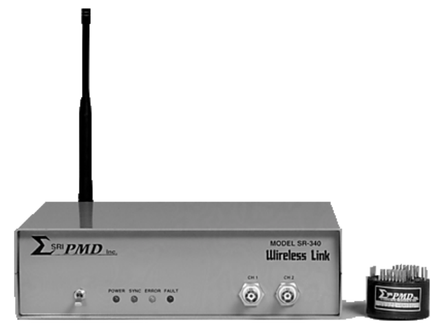
Supporting anywhere
from 1 to 16 sensor
channel inputs, all
Series 300 products
provide both highly
accurate analog and
high-speed digital
measurement outputs.
FIGURE 1-1 SRI/PMD WIRELESS LINK PRODUCT
1.1 Scope
This manual describes the SRI/PMD Series 300 Digital Telemetry Product Line,
including both transmit and receive processing units. The manual includes
specifications, design description, installation, and operation instructions
along with routine maintenance requirements for these products.
1.2 Product Overview
SRI/PMD (formerly known as Physical Measurement Devices or simply PMD) has
been designing and producing ruggedized wireless telemetry systems for in
excess of 25 years. An old slogan in the instrumentation community states
that "Measurement is the beginning of knowledge". Previous versions of PMD's
Wireless Link
product have assisted customers in gaining insight into
operational parameters which were, at best, difficult to acquire with any
amount of reliability or longevity, if not totally unobtainable.
With the advent of the new, fully digital, SRI/PMD Wireless Link
products,
potential users are being offered an improved solution that not only provides
better technology for existing customers and applications, but also
significantly expands the possible uses of these designs. By offering:
• lower cost, • improved measurement accuracy,
• true "hands-off" operation, and
• more robust and user selectable wireless communications methods,
these products offer a cost effective and timely solution to a multitude of
here-to-fore "hard-wired" applications.
OM-06-320 REV E
- 2 - 99-500-001
In a nutshell, telemetry can encompass the entire process by which a
measurement value is obtained, possibly quantified, qualified, or processed in
other ways, and then transmitted via some mechanism to the "end user" for
final processing or response actions. The "end user" in this case may be a
human for manual interpretation and analysis or, more often, a machine for
automated processing functions. The phrase "Digital Telemetry" simply
specifies that the methodology utilized to obtain, process, and transmit the
measurement data incorporates digital techniques, a highly efficient and more
reliable means of handling data processing and transmission.
Typical measurements which telemetry can provide access to include:
temperature, speed, direction, motion,
location, distance, displacement, strain,
torque, energy, power, pressure,
humidity, density, ...
Furthermore, many applications require access to multiple and/or a variety of
these measurements at the same time to allow for meaningful interpretation of
the data. One of the significant benefits of digital telemetry is that it can
be easily and readily customized to the end user requirements, allowing
various measurement (or sensor) inputs to be sampled nearly simultaneously,
cross correlated if need be, and presented as parallel analog or digital
outputs to the end user. For certain implementations, the sampling and
correlation algorithms can be configured in real-time, providing for adaptive
measurement and response requirements.
1.3 Product Description
The series 300 products are available in a variety of design options. The ST-
320/SR-340 versions of products provide digital telemetry capability operating
in the versatile 902 to 928 MHz ISM frequency band while the ST-360/SR-380
versions operate in the classic 88 to 108 MHz FM frequency bands. Based on
the exact end-user requirements, an optimized product choice can be found to
provide extremely robust wireless communications, even in indoor environments
where building structures may obstruct a direct line-of-site transmission or
in contaminated environments such as inside engine compartments.
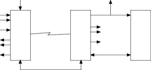
The following diagram presents a simplified overview of the latest generation
SRI/PMD Wireless Link
system.
...
Sensor Inputs
from
User Platform
(up to 16)
Excitation
Voltages ...
Digital
Telemetry
Transmitter
VDC
Wireless Link Digital
Telemetry
Receiver
Optional
Personal
Computer
with
Support
Software,
Extended
Software,
and/or
Sample
Display
Software
Standard Serial
Interface
Offline Programming
Interface
...
Analog
Outputs
(up to 18)
Digital Outputs
FIGURE 1-2 SYSTEM OVERVIEW
OM-06-320 REV E
- 3 - 99-500-001
As shown, the system consists of the following major elements:
1)
The Digital Telemetry Transmitter is a miniaturized and ruggedized radio
frequency (RF) transmitter providing the interface circuitry to select
and sample up to 16 sensor inputs and transmit the detected readings in
digital format over the Wireless Link.
2)
The Digital Telemetry Receiver provides the logic to recover the
transmitted data, detect and account for errors which might have been
introduced via the transmission path, and output error free and
digitally compensated samples of the sensor data in both analog and
digital output formats. The receive system also supports an optional
interface to a standard personal computer for status, control, and
analysis functions.
3)
The optional Personal Computer can be utilized to execute additional
software packages available from SRI/PMD. These optional support
software packages include:
a) Standard support software for monitoring general system
health, communications performance, and sensor gain/offset
calibration functions.
b) Extended support software providing for editing of sensor
definitions including type, sampling frequency, filtering,
measurement ranges, and so forth.
c) Display capture/display software for storing measurement
data to the PC disk or displaying the data in
graphical/scope type formats.
The transmitter portion of the series is available in a variety of shapes and
sizes depending on the exact end user requirements. This includes
miniaturized, single channel versions, or versatile, multi-channel, mixed
sensor type packages. The design also readily supports custom packaging for
unique end user applications.
The receiver is offered as both a stand-alone desk or bench top enclosure
configuration or as a 19” rack mountable chassis.
The communications link for the telemetry transmission is supported in either
the popular 900 MHz ISM band or the classic 90 MHz FM band. Depending upon
the exact application, an ideal solution is available to provide a robust and
reliable communications path.
1.4 Model Numbers
Each version of the Series 300 products assigned a model number. Transmitters
for this series are always designated as an ST-3xx where xx defines the exact
model type. Similarly, receivers are designated as an SR-3xx. The following
table provides an overview of each of the available standard models for this
series.

OM-06-320 REV E
- 4 - 99-500-001
TABLE 1-1 SERIES 300 MODEL DESCRIPTIONS
Model
Number Description
ST-321 A 900 MHz Wireless Link Transmitter housed in a 1.75” diameter, <
1” tall disk shaped epoxy compound mold. Intended for severe
environment applications. Available in 1 to 16 sensor input
channel versions.
ST-325 A 900 MHz Wireless Link Transmitter housed in a 1.3” x 3.8” by
5.6” plastic casing. Intended for non-shock, industrial type
applications. Available in 1 to 8 sensor input channel versions.
ST-326 Same product and versions as the ST-321 but fully tested and
certified for FCC part 15 unlicensed operation.
ST-361 A 90 MHz Wireless Link Transmitter housed in a 1.75” diameter, <1”
tall disk shaped epoxy compound mold. Intended for severe
environment applications. Available in 1 to 16 sensor input
channel versions.
ST-363 A 90 MHz Wireless Link Transmitter housed in a 1.2” x 3.6” x 0.65”
moon shaped epoxy compound mold. Intended for automotive piston
mount applications. Available in 1 to 16 sensor input channel
versions.
ST-364 A 90 MHz Wireless Link Transmitter housed as 2 individual 0.75” x
0.6” x 0.4” packages. Intended for miniaturized, severe
environment applications. Limited to fixed frequency and single
sensor input channel version.
ST-366 A 90 MHz Wireless Link Transmitter housed in a 1.3” x 3.8” by 5.6”
plastic casing. Intended for non-shock, industrial type
applications. Available in 1 to 8 sensor input channel versions.
SR-341 Benchtop receiver compatible with any model ST-32x transmitter
model. Available in 1 to 18 output channel versions.
SR-342 19” rack mount receiver compatible with any model ST-32x
transmitter model. Available in 1 to 18 output channel versions.
SR-381 Benchtop receiver compatible with any model ST-36x transmitter
model. Available in 1 to 18 output channel versions.
SR-382 19” rack mount receiver compatible with any model ST-36x
transmitter model. Available in 1 to 18 output channel versions.
1.5 Technical Specifications
A summary of the technical specifications and characteristics of the
referenced telemetry equipment is presented in the paragraphs that follow.

OM-06-320 REV E
- 5 - 99-500-001
1.5.1 Transmitter Specifications
The specifications indicated in the following table apply to the Digital
Telemetry Transmitter.
TABLE 1-2 TRANSMITTER SPECIFICATIONS
PARAMETER SPECIFICATION
OUTPUT FREQUENCIES 8 Channels from 902 to 928 MHz (Series ST-320)
88 to 108 MHz in 200 KHz Channels (Series ST-360)
MODULATION FORMATS Minimum Shift Keyed (MSK) -or-
Standard Frequency Shift Keyed (FSK)
NUMBER OF SENSOR INPUTS Up to 16
INPUT SENSOR LEVEL RANGE Programmable within the range of 0.625 uVDC to 5 VDC.
SENSOR EXCITATION Optional sensor excitation voltage driven during
sensor sampling period. Excitation voltage is
selectable from 0.625 to 5 VDC.
TYPICAL SENSOR TYPES Absolute voltage measurements, such as Type J/K
Thermocouples (up to 1000° measurement range),
Displacement Sensors, Generic Analog Voltages, ...
Relative voltage measurements, such as Strain Bridges
(120, 350 ohm, or 700 ohm, 4 arms, up to +/- 2000
uStrain measurement range), Pressure Transducers, ...
Custom
MEASUREMENT RESOLUTION 8 bits
SAMPLING RATE Up to 3 K samples per second (Series ST-320)
Up to 27 K samples per second (Series ST-360)
SENSOR MULTIPLEXING OPTIONS High speed sequential, or optional dwell/step
operation
Custom
INPUT POWER +7 Vdc to +18 Vdc
Custom
POWER CONSUMPTION < 20 mA (excluding sensor loads on excitation outputs)
OPERATING TEMPERATURE Standard - 0 to +70° C
Industrial - 0 to +85° C
Automotive – 0 to +125° C (ST-360 only)
ACCELERATION 5,000 G Rotational Typical
1.5.2 Receiver Specifications
The specifications indicated in the following table apply to the Digital
Telemetry Receiver.

OM-06-320 REV E
- 6 - 99-500-001
TABLE 1-3 RECEIVER SPECIFICATIONS
PARAMETER SPECIFICATION
RECEIVE/DEMODULATION CAPABILITIES Compatible with transmitter waveform
NUMBER OF ANALOG OUTPUTS Up to 18
SENSOR TO ANALOG CHANNEL ASSIGNMENTS Selectable
ANALOG OUTPUT RANGES 2 Channels fixed at 0 to 5 Vdc
Additional channels selectable from 0 to 5
Vdc, +/- 5 Vdc, 0 to 10 Vdc or +/- 10 Vdc
ANALOG OUTPUT RESOLUTION 2 Channels fixed at 8 bits
Additional channels 12 bits
DIGITAL OUTPUT 16 bits of parallel digital samples
6 bit channel indicator
Data Strobe
Sample Error Indicator
ERROR DETECTION Data checksum capable of detecting error
rates of up to 1 in 100
SENSOR DATA COMPENSATION OPTIONS Fixed gain/offset compensation
TX operational temp dependent compensation
Custom
DATA PROCESSING OPTIONS None
Infinite Impulse Response Averaging
(K = ½, ¼, or 1/8)
Custom
INPUT POWER +12 Vdc (AC/DC Wall Plug Standard)
POWER CONSUMPTION < 12 Watt typical
PACKAGING OPTIONS 9” x 7” x 3” Bench Top Enclosure
1U 19” Rack Mount
Custom
OPERATING TEMPERATURE Standard - 0 to +70° C
Industrial - 0 to +85° C
1.5.3 Optional Accessory Equipment and Software
In addition to the standard Digital Telemetry Equipment listed above, the
following optional support equipment is also supported.
TABLE 1-4 OPTIONAL SUPPORT EQUIPMENT
DESCRIPTION
Antenna’s for the Digital Telemetry Receiver. Typically available in ¼ or ½ wavelength versions
for either direct mounting onto the enclosure, as a stand-alone bench/desktop standing unit, or
as a magnet mounted unit.
Batteries for operating the Digital Telemetry Transmitter, available in rechargeable or
disposable versions.
Inductively coupled power generator modules for shaft or piston mount applications. Generates
the 7 Vdc power required by the Digital Telemetry Transmitter for these applications.
OM-06-320 REV E
- 7 - 99-500-001
Software for a standard Personal Computer. May include the following packages:
Standard Software Package (included with all systems):
Basic system support functions including query telemetry system, monitor self-test
results, print a detailed system configuration report, ...
Link analysis functions for the Digital Telemetry System. Provides a means to analyze
all potential communications links for the system to select the optimum channel. Also
provides error rate analysis capabilities to determine expected link performance
characteristics as well as online monitoring features of an active systems
transmission characteristics.
Calibration control functions for the Digital Telemetry System. Provides a means for
a user to alter the compensation and calibration data associated with a transmitter
based on actual sensor or other types of measurement errors.
Extended Software Package:
Configuration control functions for the Digital Telemetry System. Allows a user to
reassign sensor and analog channels, reconfigure a transmitter for alternate sensor
types, alter the transmission bandwidth allocation of the Wireless Link, set filtering
controls for individual channels, and so forth.
Display Software Package:
Sample capture/display functions for the Digital Telemetry System. Provides real time
capture of data samples from the Digital Telemetry Receiver and displays the samples
in a scope like format on a PC while also supporting the means to save the samples to
disk for later viewing or analysis by other programs.
OM-06-320 REV E
- 8 - 99-500-001
SECTION 2 DIGITAL TELEMETRY SYSTEM DESCRIPTION
Series 300 Wireless Link Digital Telemetry Systems are accomplished with an
optimum mix of analog and digital circuitry in order to provide a low-cost,
flexible system capable of handling a wide variety of telemetry requirements.
Utilization of state-of-the-art design technology combined with a latest
generation micro-controller allows the design to meet requirements of a high
performance, high reliability communications link for transferring measurement
data while still maintaining a highly cost-effective price.
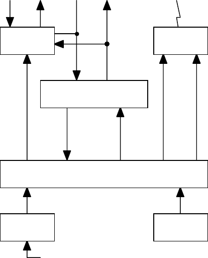
2.1 Transmitter Details
Figure 2-1 presents a more detailed overview of a Digital Telemetry
Transmitter.
Channel
Select
Gain and
Excitation
Select
Analog
Input
Up to 16
Sensor
Inputs
Up to 16
Excitation
Outputs
Single
Sensor
Inputs
Single
Excitation
Outputs
Hardware
Build
Option
Digital
Data
Stream
Channel
Select
Wireless
Link
External Programming Interface
Analog
Input 2
Micro
Controller
Temperature
Sensor
Optional
Multiplexers
Signal
Contioning
Config Data
in EEProm
FM
Transmitter
FIGURE 2-1 TRANSMITTER BLOCK DIAGRAM
At the heart of the transmitter design is a high-speed micro-controller with
embedded analog to digital conversion capabilities. For most series 300
products, execution processing of the micro-controller is determined via
configuration data stored within electronically erasable programmable read-
only-memory (EEProm). The configuration tables contained within this memory
dictates operational characteristics such as the number of input sensor
channels, the type of each input, the desired sampling sequence to be utilized
for data transmission purposes, output RF frequency selection, and so forth.
Since the EEProm memory space can be reprogrammed via the external programming
OM-06-320 REV E
- 9 - 99-500-001
interface to the Digital Telemetry Receiver, all significant operational
characteristics of the Transmitter can be readily modified, even for fielded
units. Certain single channel, miniaturized series 300 models (e.g., ST-364)
do not support the transmitter EEProm memory space and are built with fixed
gain and sampling characteristics.
For transmitters limited to a single input sensor channel, onboard circuitry
is available to process the input measurement data through signal conditioning
circuitry. When the number of input sensor channels exceeds one (1), an
optional multiplexer card is provided. This card includes a sixteen (16) to
one (1) multiplexer to support connecting multiple sensor channels to the
single input of the main board. All sensor-input logic also includes
associated excitation voltage output circuitry that may be utilized to drive
sensors requiring an input voltage, such as balanced bridges.
Operation of the signal conditioning logic is controlled via the micro-
controller to establish appropriate gain settings. This powerful feature of
the design allows the same circuitry to be reprogrammed to support a wide
variety of potential input sensor types. Furthermore, because the sensor type
information is also included in the EEProm configuration tables, these
settings can be changed for various user requirements.
Data transmission across the wireless link is accomplished with dual data
channels known as the primary and the background channels respectively. The
primary data channel is allocated in excess of 90% of the transmit bandwidth
and typically includes the input sensor data measurement information. The
background channel is relatively low rate and contains information required
for receive side frame synchronization and error detection.
Another key feature to the design is that the background channel can also be
utilized to transmit data pertaining to the current transmitter operational
temperature. For applications which require a high degree of data accuracy,
this information may be utilized to support real-time temperature based
compensation of sensor data samples through the receive chain.
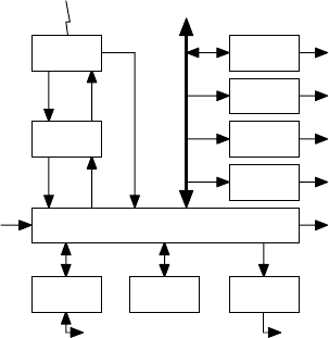
2.2 Receiver Details
Figure 2-2 presents a more detailed overview of the Series 300 Digital
Telemetry Receiver’s.
Channel
Select
Up to 16
Analog
Outputs
Digital
Data
Stream
Wireless
Link
Remote Interface
Config
Control
Digital
Data
Words
Programming Interface
to Transmitter
Receive
Strength
Signal
Indicator
Digital
Outputs
2 Analog
Outputs
Optional
Extended
I/O’s
Front Panel
LED’s
DIP
Switches
Back end
Micro Controller
Prog/Config
EEProm
Other Ext
Interfaces
RS-232
Interface
Program
Interface
FM
Receiver
Front End
Micro Cont
Opt Ext
Analog Chan
Digital
Interface
Onboard
Analog Chan
FIGURE 2-2 RECEIVER BLOCK DIAGRAM
OM-06-320 REV E
- 10 - 99-500-001
The receiver incorporates two (2) high-speed micro-controllers to provide for
full real time processing of incoming measurement samples. The front-end
micro-controller interfaces with the Wireless Link receiver to recover bit,
byte, word, and frame synchronization with the incoming data stream. The
process of achieving this level of synchronization is known as the acquisition
process and is in-turn reflected on the front panel “SYNC” indicator. Once
frame synchronization has been achieved, the “SYNC” indicator is illuminated.
After proper acquisition, the front-end micro-controller begins sending
received data sensor samples to the back-end processor. In parallel with this
process, the front-end performs error detection functions via embedded
checksums within the incoming data. All received data samples during a frame
detected to have an error within it are flagged as error samples.
The back-end micro-controller accepts the data samples and provides
configurable data processing on the information prior to outputting the data
to analog and digital output channels. Data processing, in this case, may
include standard gain adjustment multiplication, offset addition, transmitter
temperature dependent data compensation, as well as alternate data averaging
and or filtering functions.
Program execution of the back-end micro-controller is directed via code and
configuration tables stored in EEProm memory space resident on the card. The
contents of this memory space can be loaded via the remote control RS-232
interface to a standard personal computer. This feature allows fielded
Digital Telemetry Receiver systems to be upgraded to new releases of
executable firmware, or modified to support new transmitters or alter the
processing characteristics of existing transmitters.
The minimum configuration of a Digital Telemetry Receiver supports two (2)
analog output channels. These onboard channels, designated as Analog Channel
1 and 2, are limited to eight (8) bits of data resolution and support an
output voltage range of 0 to 5 Vdc. An optional extension card may be added
to support up to 16 additional analog output channels (designated as Analog
Channels 3 through 18). These channels support 12 bits of data resolution and
can be programmed to cover an entire output voltage range of -10 to +10 Vdc.
Furthermore, the optional extension card contains highly accurate voltage
reference circuitry to guarantee the accuracy of the +/- 10 Vdc range to
better than +/- 0.2 percent.
2.3 System Data Processing Overview
The Series 300 products can be configured to process input sensor measurements
anywhere within the range of 0 to 5 VDC. Typically, instrumentation sensors
do not utilize this entire measurement range. For instance, a single active
arm, 350 ohm strain gage with 5 V excitation will only produce a +/- 1.25
millivolt DC (mVDC) signal for strain levels of +/- 500 micro-strain (uE).
Obviously, these signal levels are not overly useful to most end-user
processing equipment.
To create a useful signal, the product line provides programmable gain,
offset, and data filtering functions on the input sensor signals. The
following sections describe this processing in more detail.

OM-06-320 REV E
- 11 - 99-500-001
2.3.1 Gain and Offset Processing
The Digital Telemetry process applies various stages of gain to the input
signal such that the configured measurement input levels of the sensor end up
corresponding to a specified output analog voltage range (e.g., -10 to +10
VDC). For the strain gage example, this implies a gain of x 8000 in order to
translate -1.25 mVDC to -10 VDC and +1.25 mVDC to +10 VDC.
A gain of this magnitude is never 100% accurate. Furthermore, small errors
introduced by the exact mechanical installation of the sensor, ground
differentials, cabling losses, or transmitter sensor input to digital
measurement processing circuitry end up causing additional errors. These
errors are reflected as incorrect gain or variations in offset (i.e., where a
0 reading does not correspond to a 0 output).
In order to compensate for these factors, the Digital Telemetry System
provides programmable gain and offset control that are invoked at various
stages within the system. The following figure provides a very simplistic
overview of this process.
Sensor
Input System
Gain System
Offset Output
Value
VDC Voltage
Unipolar Range limited
from 0 to +5 VDC or
Bipolar Range limited
from -2.5 to +2.5 VDC.
Installation, connection,
or sensor interface
circuitry characteristics
contribute to gain and
offset errors.
Multiplier Value
Accomplished via
Programmable Gain
Amplification in Digital
Telemetry Transmitter
combined with Digital
Multiplier in Receiver
()
Adder Value
Accomplished via
Digital Adder in
Receiver (limited to
-10.00 to +20.00).
Analog or Digital
Representation of
Output VDC Voltage
Programmable for
output range from -10 to
+10 VDC.
FIGURE 2-3 DATA PROCESSING OVERVIEW
The system gain and offset values are set to not only translate the input
measurement signal range to the desired analog output voltage range, but can
also be utilized to account for the gain and offset errors discussed above.
The following figure presents a more detailed view of the entire signal
processing of the Digital Telemetry System.

OM-06-320 REV E
- 12 - 99-500-001
Sensor
Input with Gain
and Offset Errors
Transmitter
Unipolar/Bipolar
Select
Independently
Configured for each
Sensor Channel via
Transmit EEProm Tables
for centering Sensor -
Input at 0 (Unipolar) or
2.5 VDC (Bipolar).
Transmitter
Gain
Amplifier
Independently
Configured for each
Sensor Channel via
Transmit EEProm Tables
for x1 to x2500 gain.
Transmitter
Analog to Digital
Conversion
Conversion from Analog
0 to +5 VDC Signal to
Digital Value from 0x00
to 0xFF.
Differential Sensor +
and Sensor - Inputs
Wireless
Link
Transmitter
Wireless
Link
Receiver
Receiver
Unipolar/Bipolar
Floating Point Convert
Conversion of Digital Integer
Values to Floating Point
Representation where 0x00 goes
to 0.0 (Unipolar) or -10.0
(Bipolar) and 0xFF goes to +20.0
(Unipolar) or +10.0 (Bipolar).
Receiver
Gain
Multiplier
Multiplication of
Floating Point
Measurement by
Configurable Gain
Multiplier (0.01 to 9.99).
Receiver
Offset
Adder
Addition of
Floating Point
Measurement to
Configurable Offset
Adder (-10.0 to +20.0).
Analog
Output
Channel
Output of Floating
Point Value as
Analog Level in
Range of -10 to +10
VDC.
FIGURE 2-4 DATA PROCESSING DETAILS
As shown, the processing varies based on whether the measurement input is a
unipolar (i.e., positive only) or bipolar (i.e., positive and negative)
signal. For unipolar signals, the 0 reading is eventually output as a -10 VDC
analog output (for channels configured for -10 to +10 output voltage range)
and all gains are applied in a positive direction from that point. For
bipolar signals, the 0 reading is eventually output as a true 0 VDC analog
output and gains work in both directions from that center point up to the
maximum output values of -10 VDC for negative values and +10 VDC for positive
values.
The processing through the receive side can also be made dependent upon the
transmitter operational temperature at the time of the measurement. The
transmitter logic monitors it’s own temperature and periodically reports this
value across the wireless link. For sensor data which varies with temperature
(e.g., thermocouples), this feature is utilized to dynamically modify the
receiver gain multiplier and offset adder to compensate for these variations.
The table on the following page provides four (4) examples of the data
processing stages and the affects on the measurement values.

OM-06-320 REV E
- 13 - 99-500-001
TABLE 2-1 SAMPLE DATA PROCESSING STAGES
Processing
Stage Case 1
Generic
Unipolar 0 to
5 VDC Analog
Input
Case 2
Generic
Bipolar +/-
25 mVDC
Analog Input
Case 3
Unipolar Type
J Thermocple
for 32 to
500°
°°
° F
Measurements
Case 4
Bipolar 350
Ohm Strain
Gage for +/-
500 uE
Measurements
with +5V
Excitation
Sensor Input 0 VDC to 5
VDC -25 mVDC to
+25 mVDC 0 VDC (32°
°°
° F)
to +28.5 mVDC
(500°
°°
° F)
-1.25 mVDC (-
500 uE) to
+1.25 mVDC
(+500 uE)
Transmit
Unipolar
Bipolar
Select
0 VDC to 5
VDC 2.475 VDC (-
25 Input) to
2.525 VDC
(+25 Input)
0 VDC (32°
°°
° F)
to +28.5 mVDC
(500°
°°
° F)
2.49875 VDC
(-500 uE) to
2.50125 (+500
uE)
Transmit Gain
Amplifier = x1
0 VDC to 5
VDC
=x50
1.25 VDC (-25
Input) to
3.75 VDC (+25
Input)
= x100
0 VDC (32°
°°
° F)
to 2.85 VDC
(500°
°°
° F)
= x1000
1.25 VDC (-
500 uE) to
3.75 VDC
(+500 uE)
Transmit
Analog to
Digital
Convert
0x00 (0
Input) to
0xFF (5
Input)
0x40 (-25
Input) to
0xc0 (+25
Input)
0x00 (32°
°°
° F)
to 0x91 (500°
°°
°
F)
0x40 (-500
uE) to 0xC0
(+500 uE)
Receive
Floating
Point Convert
0.0 (0 Input)
to 20.0 (5
Input)
-5.0 (-25
Input) to
+5.0 (+25
Input)
0.0 (32°
°°
° F)
to 11.375
(500°
°°
° F)
-5.0 (-500
uE) to +5.0
(+500 uE)
Receive Gain
Multiplier = x1.0
0.0 (0 Input)
to 20.0 (5
Input)
= x2.0
-10.0 (-25
Input) to
+10.0 (+25
Input)
= x1.76
0.0 (32°
°°
° F)
to 20.0 (500°
°°
°
F)
= x2.0
-10.0 (-500
uE) to +10.0
(+500 uE)
Receive
Offset Adder = 0.0
0.0 (0 Input)
to 20.0 (5
Input)
= +10.0
0.0 (-25
Input) to
+20.0 (+25
Input)
= 0.0
0.0 (32°
°°
° F)
to 20.0 (500°
°°
°
F)
= +10.0
0.0 (-500 uE)
to +20.0
(+500 uE)
Analog Output
Channel -10 VDC (0
Input) to +10
VDC (5 Input)
-10 VDC (-25
Input) to +10
VDC (+25
Input)
-10 VDC (32°
°°
°
F) to +10 VDC
(500°
°°
° F)
-10 VDC (-500
uE) to +10
VDC (+500 uE)
OM-06-320 REV E
- 14 - 99-500-001
2.3.2 Data Filtering
In addition to offset and gain processing, the Series 300 Product Line also
supports digital data filtering of the measurement samples. Filtering may be
utilized to eliminate high frequency noise from the sensor inputs which may be
present due to power supply noise or other equipment operating near the
telemetry system.
Standard filters supported by the system all utilize the following basic
formula:
OUT(n) = (K x IN(n)) + ((1-K) x OUT(n-1))
In this formula, OUT(n) implies the output value to the analog channel for
time period “n”, while IN(n) implies the new measurement sample for the analog
channel during time period “n”. K is a simple constant that may be programmed
to be equal to ½, ¼, or 1/8, 1/16, 1/64, 1/256.
This type is filter is known as an “Infinite Impulse Response” (or IIR)
filter, since any given input sample affects all future outputs. On a custom
basis, a more sophisticated “Finite Impulse Response” (or FIR) filter, or
higher order IIR filters are available.
2.4 Digital Telemetry Control Software
Each Digital Telemetry System is typically delivered with Control Software
compatible with running on a standard Personal Computer (PC) operating under
the Windows 95 or 98 operating system. This software provides a number of
critical functions for the system, including the following:
Initial Set-up and Introduction
Assistance in getting started with the Digital Telemetry System
Communications Analysis Functions
On-line monitoring of communications performance
Analysis of all possible communications frequencies
Altering of the wireless link frequency and/or baud rate
System Calibration
Modifications to system gain and offset settings
Table Control Functions
List functions of currently defined Digital Telemetry Systems
Download functions to update or restore EEProm memory space
In addition, an extended version of the above software may be purchased which
provides the user full configuration control over transmitters and receivers,
including altering sensor definitions, channel assignments, and so forth.
Later sections of this document provide a detailed description of the
operation of this control software. The remaining portion of this section
describes some of the system elements that are referenced by this software and
defines the meaning of each.
OM-06-320 REV E
- 15 - 99-500-001
2.4.1 Serial Numbers and Versions
Each Series 300 Product is assigned a unique 4-digit serial number to identify
the receiver or transmitter and its assigned hardware configuration. In
addition to the serial number, a single digit version number is also utilized
to delineate software configurations for the hardware element. For instance,
a transmitter built for a single sensor channel input may be configured via
software to accept a 350-ohm strain gage input (version 0) and then be altered
to support a type J thermocouple input (version 1).
The initial version number for any factory delivered item is 0. As such, a
new receiver assigned serial number 0123 will be displayed by the control
software as “Receiver S/N 0123 V0”. Similar designations are utilized for the
transmitters. Hence, in the above transmitter example, the unit would be
displayed with two (2) designations as “Transmitter S/N 0123 V0” and
“Transmitter S/N 0123 V1”.
Any given receiver can support up to 16 transmitters or versions of
transmitters. Beyond this, the user must delete unused versions of
transmitters or purchase additional receiver units.
2.4.2 File Structure
Corresponding to the Digital Telemetry System are disk files on the installed
program directory referred to as a Receiver Definition Tables (RDT’s) and
Transmitter Definition Tables (TDT’s). These are further identified by the
unit serial number. Hence, for the examples given in the previous section, a
disk file would exist in the program directory called “RDT01230.cfg” along
with disk files called “TDT01230.cfg” and “TDT01231.cfg”.
The above referenced files are mirror images of what is stored in the receiver
EEProm in order to fully define the Digital Telemetry System. They include
information such as the unit serial number, number of configured and/or active
sensor and analog channels, transmit frequency and baud rate, and so forth.
The control software provides an easy means of downloading these file images
to the receiver in case EEProm space is corrupted for some reason. It should
be noted that if the control software has access to both the disk files and to
EEProm space in the receiver via the serial port connection, it will always
utilize the EEProm tables as opposed to those stored on disk.
Along with the above information, the TDTxxxxx.cfg files also contain
calibration information for the corresponding transmitter. If the system
calibration data is altered via the control program, new values are stored
both in the EEProm memory of the receiver and on the disk file. Users are
encouraged to back-up these disk files to an alternate media source if changes
are made. In addition, if an installation of the Digital Telemetry Control
Software is performed on another PC, the installed files will contain
calibration data from the factory. Users may wish to copy updated files
between PC’s to insure the latest data is maintained.
Along with the above files, transmitters definitions provided by SRI/PMD also
include files named “TDTxxxxx.fac”. These files contain the definition and
calibration data for the transmitter as it was delivered from the factory.
The Digital Control Software discussed in later sections of this document use
these files to support “revert” functions to factory settings. Users may also
utilize these files to restore factory defaults by manually copying the “.fac”
files to the “.cfg” version of the same file.

OM-06-320 REV E
- 16 - 99-500-001
Finally, anytime a system calibration is performed utilizing the Digital
Control Software, a file named “TDTxxxxx.cal” is created if it doesn’t already
exist on the PC. The “.cal” file contains detailed information on the
calibration process which was performed and is utilized to print out a report
on this information. If the “.cal” file already exists from a previous
calibration, data on the new calibration is added onto the end of the file.
2.5 Configurable System Parameters and Processing
As indicated above, the power of the system architecture is contained within
the number of features that are programmable and/or selectable. This not only
allows the same product to be utilized for a wide variety of applications but
also supports modifications to existing equipment for new applications or data
processing schemes.
The following table indicates some of the programmable features of the system
and provides standard, optional, or custom selections that may be specified
for each parameter.
TABLE 2-2 SELECTABLE CONFIGURATION AND PROCESSING OPTIONS
PARAMETER PROGRAMMABLE OPTIONS OR SETTINGS
Transmission
Data Rate 6.25 to 32.6 Kbps (ST-320)
62.5 to 250 Kbps (ST-360)
Number of Sensor
Inputs Standard : 1, 2, 4, 8, or 16
Custom : 3, 5 - 7, 9 - 15, 17+
Sensor Types Standard
Type J/K Thermocouple
Strain Gages (1, 2 or 4 active arms)
Pressure Transducers
Accelerometer
Thermistors
Generic 0 to 5 VDC
Generic Analog Voltage
Custom
User specified
Measurement
Resolution 8 bit
Sensor Sampling
Algorithms Maximum Rate Sequential Sampling
Each sensor channel is sampled sequentially and issued at the maximum rate
supported by the transmission path.
Dwell/Step Sequential Sampling
The sensor channels are selected sequentially but at each selection setting
the system dwells for a configurable number of output sample periods (from 2
to 65535 samples (e.g. > 28 seconds)) before the next sensor channel is
selected.
Custom
Mixed or alternate sampling rates, sensor channel ordering schemes, or
measurement resolution settings.

OM-06-320 REV E
- 17 - 99-500-001
Sensor to Analog
Channel
Assignment
Standard
Varies based on number of input sensor channels versus available analog
channels. Assignments are sequential in nature with lower number sensor
inputs given priority to analog assignments.
Optional
Any sensor input channel to any analog output channel.
Analog Output
Voltage Range Standard
Fixed at 0 to +5 VDC for analog channels 1 and 2. Selectable from -10 to +10
VDC, +5 to -5 VDC, 0 to +10 VDC, or 0 to +5 VDC for analog channels 3 through
18.
Optional
Any voltage range within maximum supported ranges.
Sample
Processing Logic Standard
None, standard gain/offset compensation, sample compensation based on TX
operating temperature, and/or IIR filtering (K = ½, ¼, or 1/8, 1/16, 1/64,
1/256).
Custom
FIR filtering, custom filtering, multi-channel math functions, other.
The ease with which these parameters can be modified not only allows SRI/PMD
to provide a Digital Telemetry System ideally suited for an initial customers
requirements, but also supports modifying the systems definition and
characteristics to meet new and different sets of needs, even for previously
fielded equipment’s.

OM-06-320 REV E
- 18 - 99-500-001
SECTION 3 RECEIVING, INSPECTION AND INSTALLATION
3.1 Unloading and Unpacking
NOTE
If shipping carton is damaged upon
receipt, request carrier’s agent be
present during unpacking and inspection of
the system.
Upon receipt of the equipment, inspect the shipping container for damage. If
the container or the cushioning material is found damaged, they should be kept
until the contents of the shipment have been verified for completeness and the
equipment has been inspected for mechanical and electrical defects. If the
contents are incomplete or if there is a mechanical or electrical defect,
please notify:
SRI/PMD
751 North Drive
Melbourne, Florida 32934
3.2 Receiving Documentation
Each Digital Telemetry System is shipped with a copy of this manual and a
packing slip. The packing slip should be carefully checked against the
contents of the shipping container.
3.3 Installation and Connection Requirements
Users should be aware that the Digital Telemetry Receiver and the Digital
Telemetry Transmitter contain sensitive electronic components. Proper
“Electrostatic Discharge” (ESD) handling procedures should be utilized for
this equipment as with any other electronic apparatus.
The transmitter may be delivered in a variety of standard or custom molds
based on the actual end application of the telemetry system. The available
connections and pin locations will vary based on the packaging style and
purchased configuration.
The receiver is typically delivered either as a stand-alone bench or desktop
enclosure or as a standard 19 inch rack mountable chassis. Due to its light-
weight, slides are not provided as part of the standard product for the rack
mount version. Holes on the front panel ears may be used to secure the
chassis directly into the rack.
Prior to establishing external connections from the transmitter to any sensor
equipment or the receiver to any user processing equipment, it is recommended
that both units be validated in a stand-alone mode as discussed in section 4.0
of this document.

OM-06-320 REV E
- 19 - 99-500-001
3.4 Transmitter Signal Definitions and Characteristics
This section describes the standard connector interfaces of the Digital
Telemetry Transmitter, including the definition and associated requirements of
all signals. As previously indicated, pin locations and assignments will vary
based upon the exact model of Transmitter that is purchased. Appendix A of
this document provides model dependent pin assignments and interconnect
information.
The following table details the signal definitions common to all models of the
Digital Telemetry Transmitters.
TABLE 3-1 TRANSMITTER SIGNAL DEFINITIONS, AND CHARACTERISTICS
SIGNAL DESCRIPTION
PROGRAMMING INTERFACE SIGNALS
PROG_VCC ALTERNATE 5 VDC POWER SUPPLIED TO TRANSMITTER WHEN IT IS BEING REPROGRAMMED FROM
THE DIGITAL TELEMETRY RECEIVER.
PROG_GND GROUND SIGNAL UTILIZED WITH THE PROGRAMMING CABLE.
PROG_RESET* MICRO-CONTROLLER RESET LINE UTILIZED WITH THE PROGRAMMING CABLE.
PROG_DATA DATA LINE UTILIZED TO REPROGRAM EEPROM SPACE OF THE TRANSMITTER.
PROG_CLOCK CLOCK LINE UTILIZED TO REPROGRAM EEPROM SPACE OF THE TRANSMITTER.
COMMON SIGNALS
VCC PRIMARY VDC POWER FOR THE TRANSMITTER DURING NORMAL OPERATION. THE SOURCE FOR
THIS POWER MAY PROVIDE ANYWHERE FROM +7 TO +18 VDC AS THE PRIMARY POWER LEVEL.
EXCESSIVELY NOISY GROUND CHARACTERISTICS ON THIS INPUT LINE MAY BE REFLECTED IN
POOR MEASUREMENT ACCURACY RESULTS. THE PRIMARY POWER SOURCE MUST BE ABLE TO
SUPPORT A MINIMUM 20 mA LOAD ON THIS INPUT LINE.
GND PRIMARY GROUND FOR THE TRANSMITTER. EXCESSIVELY NOISY GROUND CHARACTERISTICS ON
THIS INPUT LINE MAY BE REFLECTED IN POOR MEASUREMENT ACCURACY RESULTS.
EXC+COM EXCITATION OUTPUT + VOLTAGE COMMON. THIS OUTPUT WILL ALWAYS BE AT THE POSITIVE
EXCITATION VOLTAGE (+5, +2.5, +1.25, OR +0.625 VDC) AND SHOULD BE CONNECTED TO
ANY SENSOR CHANNEL REQUIRING EXCITATION VOLTAGES. THE OUTPUT SHOULD BE COMMON TO
ALL SENSORS REQUIRING THIS CAPABILITY. EACH SENSOR ON THIS LINE MAY EXHIBIT A
MINIMUM LOAD IMPEDANCE OF 150 OHMS. NOTE - ADDITIONAL CURRENT DRAW ON THE
PRIMARY VCC DUE TO SENSOR UTILIZATION OF THIS OUTPUT IS NOT INCLUDED IN THE < 20
mA MAXIMUM CURRENT SPECIFICATION.
EXC-COM EXCITATION OUTPUT - VOLTAGE COMMON. THIS OUTPUT WILL ALWAYS BE AT APPROXIMATELY
- VDC AND SHOULD BE CONNECTED TO SINGLE CHANNEL SENSOR CONFIGURATIONS REQUIRING
EXCITATION VOLTAGES. FOR MULTIPLE CHANNEL CONFIGURATION, THE MULTIPLEXED EXC-
SIGNALS DISCUSSED BELOW SHOULD BE UTILIZED. A SENSOR ON THIS LINE MAY EXHIBIT A
MINIMUM LOAD IMPEDANCE OF 150 OHMS. NOTE - ADDITIONAL CURRENT DRAW ON THE
PRIMARY VCC DUE TO SENSOR UTILIZATION OF THIS OUTPUT IS NOT INCLUDED IN THE < 20
mA MAXIMUM CURRENT SPECIFICATION. FOR OPTIMUM MEASUREMENT ACCURACY, THE EXC-COM
SHOULD NOT BE TIED TO THE PRIMARY GROUND SIGNAL DISCUSSED ABOVE VIA ANY PATH.
SENSOR INTERFACE SIGNALS
SIG+x POSITIVE SENSOR SIGNAL INPUT FOR CHANNEL x WHERE x IS VALID FOR THE POPULATED
NUMBER OF AVAILABLE SENSOR CHANNELS (1 THROUGH 16). THIS INPUT SHOULD PROVIDE
THE POSITIVE SIDE OF THE MEASUREMENT VALUE FOR DIFFERENTIAL SIGNALS OR THE
PRIMARY MEASUREMENT VALUE FOR NON-DIFFERENTIAL SIGNALS. ABSOLUTE MAXIMUM VOLTAGE
RATING ON THIS INPUT IS 0 TO 5.5 VDC. VALID SIGNAL MEASUREMENT RANGE DEPENDS ON
SELECTED CONFIGURATION AND MAY BE VARIED VIA CONFIGURATION TABLES
SIG-x NEGATIVE SENSOR SIGNAL INPUT FOR CHANNEL x WHERE x IS VALID FOR THE POPULATED
NUMBER OF AVAILABLE SENSOR CHANNELS (1 THROUGH 16). THIS INPUT SHOULD PROVIDE
THE NEGATIVE SIDE OF THE MEASUREMENT VALUE FOR DIFFERENTIAL SIGNALS OR GROUND FOR
NON-DIFFERENTIAL SIGNALS. OTHER SIGNAL CHARACTERISTICS AND RESTRICTIONS FOR THIS
OM-06-320 REV E
- 20 - 99-500-001
INPUT ARE IDENTICAL TO SIG+x.
EXC-x NEGATIVE EXCITATION OUTPUT VOLTAGE FOR CHANNEL x WHERE x IS VALID FOR THE
POPULATED NUMBER OF AVAILABLE SENSOR CHANNELS (1 THROUGH 16). THIS OUTPUT WILL BE
EQUAL TO EXC+COM WHEN THE CHANNEL IS NOT BEING SAMPLED OR EQUAL TO EXC-COM DURING
AN ACTIVE MEASUREMENT PERIOD. THIS OUTPUT SHOULD ONLY BE CONNECTED TO THE
CORRESPONDING SENSOR PROVIDING THE SIG+x AND SIG-x INPUTS.
3.5 Receiver Indicators, Controls, and Connector Interfaces
This section describes the status, control, and connector interfaces of the
Digital Telemetry Receiver, including the types of connectors used and the
definition of the signals associated with each. In general, these connectors
are identical for all models of the Series 300 Receivers, although the
connector locations may vary.
3.5.1 Antenna Input
The Antenna input is a bulkhead mount type TNC jack located on the rear panel
and labeled “ANTENNA”. The Digital Telemetry Receiver provides the female
side of this connector and as such the user interface cable must provide the
male side.
Characteristics of this input signal are as indicated in the following table.
TABLE 3-2 RF INPUT CHARACTERISTICS
INPUT CENTER FREQUENCY 913.5 MHz (SR-340 Model)
98 MHz (SR-380 Model)
INPUT BANDWIDTH +/- 15 MHz RF BANDWIDTH
MAXIMUM INPUT SIGNAL LEVEL + 10 dBm CONTINUOUS WITHOUT DAMAGE (NOTE: PROPER
OPERATION UP TO - 10 dBm ONLY)
INPUT IMPEDANCE 50 OHMS
VSWR 2.0:1 MAXIMUM
3.5.2 VDC Input
The power input to the receiver is a standard DC power jack located on the
rear panel and labeled “VDC”. This input is compatible with the AC to DC wall
plug unit supplied with the receiver.
Characteristics of the input power signal are as indicated in the following
table.
TABLE 3-3 INPUT POWER CHARACTERISTICS
INPUT VOLTAGE 10 TO 14 VDC (+/- 5%)
CAPACITY 2 Amp (MINIMUM)
3.5.3 Remote Status/Control
The remote status/control input/output is a serial interface compatible with
the EIA Standard RS-232 (MIL-STD-188, Section 114, Unbalanced). The connector
for this interface is a 9 position D-type connector as depicted in Figure 3-1
and is labeled "REMOTE". The Digital Telemetry Receiver provides the female

OM-06-320 REV E
- 21 - 99-500-001
side of this connector and as such the user interface cable must provide the
male side.
REAR PANEL VIEW
51
96
FIGURE 3-1 REMOTE STATUS/CONTROL INTERFACE CONNECTOR
The Digital Telemetry Receiver operates as standard Data Terminal Equipment
(DTE) utilizing the signal definitions defined in the following table.
TABLE 3-4 REMOTE STATUS/CONTROL PIN ASSIGNMENTS
PIN SIGNAL INPUT/OUTPUT
1 GND - GROUND N/A
2 TD - TRANSMIT DATA OUTPUT
3 RD - RECEIVE DATA INPUT
5 GND - GROUND N/A
7 CTS - CLEAR TO SEND INPUT
8 RTS - REQUEST TO SEND OUTPUT
9 GND - GROUND N/A
The standard product does not support hardware handshaking via the CTS and RTS
signals. Custom versions incorporating this protocol can be supplied if
required.
3.5.4 Digital Telemetry Transmitter Programming Interface
The receiver provides a programming interface connection for the Digital
Telemetry Transmitter. This connection is a 5 pin DIN style connector located
on the rear panel and labeled “PROGRAM”.
The pin assignments for this connection are defined in the following table.
TABLE 3-5 PROGRAMMING INTERFACE PIN ASSIGNMENTS
PIN SIGNAL
1 DATA
2 GND - GROUND
3 CLOCK
4 VCC - +5 VDC
5 RESET*
This interface should only be utilized with the programming cable supplied
with the Digital Telemetry System. Section 4 of this manual describes the
proper utilization of this interface via the programming cable.
3.5.5 DIP Switch Control
The receiver provides an access hole on the rear panel to an internal side
actuated DIP switch. The DIP switch itself is depicted in the following
figure.

OM-06-320 REV E
- 22 - 99-500-001
REAR PANEL VIEW
ON
1 2345 678
FIGURE 3-2 DIP SWITCH CONTROL INTERFACE
The switch assignments for this interface are defined in the following table.
TABLE 3-6 DIP SWITCH ASSIGNMENTS
SWITCH SIGNAL
1 SPARE
2 SPARE
3 SPARE
4 SPARE
5 TX SELECT 3
6 TX SELECT 2
7 TX SELECT 1
8 TX SELECT 0
TX SELECT 3 through 0 act as a 4 bit control input where TX SELECT 3 is the
most significant bit (MSB) and TX SELECT 0 is the least significant bit (LSB).
Each Digital Telemetry Receiver may be configured to interface with up to 16
unique transmitters. Each transmitter is assigned an index number ranging
from 0 to 15 within the receiver when it’s configuration is loaded into the
unit. By altering the switch selections of TX SELECT 3 through 0, the
operator may select which of the 16 transmitters from which the unit is
expecting to receive data. Invalid switch settings to selections that have
not been assigned to a transmitter will cause a fault condition until a valid
selection is realized. The following table details the various switch
selections of the receiver.
TABLE 3-7 DIP SWITCH SELECTIONS
Switch 1 Switch 2 Switch 3 Switch 4 Switch 5 Switch 6 Switch 7 Switch 8 TX Selection
OFF OFF OFF OFF OFF OFF OFF OFF TX Index 0
OFF OFF OFF OFF OFF OFF OFF ON TX Index 1
OFF OFF OFF OFF OFF OFF ON OFF TX Index 2
OFF OFF OFF OFF OFF OFF ON ON TX Index 3
OFF OFF OFF OFF OFF ON OFF OFF TX Index 4
OFF OFF OFF OFF OFF ON OFF ON TX Index 5
OFF OFF OFF OFF OFF ON ON OFF TX Index 6
OFF OFF OFF OFF OFF ON ON ON TX Index 7
OFF OFF OFF OFF ON OFF OFF OFF TX Index 8
OFF OFF OFF OFF ON OFF OFF ON TX Index 9
OFF OFF OFF OFF ON OFF ON OFF TX Index 10
OFF OFF OFF OFF ON OFF ON ON TX Index 11
OFF OFF OFF OFF ON ON OFF OFF TX Index 12
OFF OFF OFF OFF ON ON OFF ON TX Index 13
OFF OFF OFF OFF ON ON ON OFF TX Index 14
OFF OFF OFF OFF ON ON ON ON TX Index 15
The assignment of internal transmitter indexes to actual transmitter serial
numbers may be viewed via support software discussed in section 4 of this
manual.

OM-06-320 REV E
- 23 - 99-500-001
3.5.6 Digital Output
The digital output is a 25 pin D-type connector as depicted in Figure 3-2. It
is located on the rear panel and labeled “DIGITAL”. The receiver provides the
female side of this connector and as such the user interface cable must
provide the male side.
REAR PANEL VIEW
13 1
25 14
FIGURE 3-3 DIGITAL OUTPUT CONNECTOR
Characteristics of these output TTL signals are as identified in the following
table.
TABLE 3-8 DIGITAL OUTPUT SIGNAL CHARACTERISTICS
OUTPUT VOLTAGE FOR A “1” 2.0 V (MINIMUM)
OUTPUT VOLTAGE FOR A “0” 0.55 V (MAXIMUM)
OUTPUT SINK CAPABILTY 64 mA
OUTPUT SOURCE CAPABILITY 32 mA
The connector provides 6 bits of analog channel address information as well as
16 bits of digital representation of the analog data value. In addition, a
data strobe line is provided to serve as a clock latch for any data change on
the interface and an error sample line indicates when data has not been
updated due to a detected receive data error. The following pin assignments
apply to this connector.
TABLE 3-9 DIGITAL OUTPUT PIN ASSIGNMENTS
PIN SIGNAL PIN SIGNAL PIN SIGNAL
1 GROUND 9 ERROR SAMPLE 17 DATA 7
2 STROBE 10 DATA 0 18 DATA 8
3 ADDRESS 0 11 DATA 1 19 DATA 9
4 ADDRESS 1 12 DATA 2 20 DATA 10
5 ADDRESS 2 13 DATA 3 21 DATA 11
6 ADDRESS 3 14 DATA 4 22 DATA 12
7 ADDRESS 4 15 DATA 5 23 DATA 13
8 ADDRESS 5 16 DATA 6 24 DATA 14
25 DATA 15
Each time a sensor sample is recovered by the receiver, the processed and
compensated data is written to this digital interface as well as being
reflected on the corresponding analog channel. The address bits are
interpreted as a 6 bit value where ADDRESS 0 is the least significant bit and
ADDRESS 5 is the most significant bit. The three (3) lower order bits reflect
a Digital to Analog Converter (DAC) address (0 through 7) while the upper
three (3) bits reflect an DAC group number (0, 1, or 2). The resulting value
indicates which receiver analog channel is being updated as shown in the
following table.
OM-06-320 REV E
- 24 - 99-500-001
TABLE 3-10 ANALOG CHANNEL TO DIGITAL ADDRESS CORRELATION
ANALOG CHAN DAC GROUP # DAC CHANNEL # OUTPUT ADDRESS
1 0 0 0x00
2 0 1 0x01
3 1 0 0x08
4 1 1 0x09
5 1 2 0x0a
6 1 3 0x0b
7 1 4 0x0c
8 1 5 0x0d
9 1 6 0x0e
10 1 7 0x0f
11 2 0 0x10
12 2 1 0x11
13 2 2 0x12
14 2 3 0x13
15 2 4 0x14
16 2 5 0x15
17 2 6 0x16
18 2 7 0x17
In this table, the 0x indicates a hexadecimal representation of the 6 ADDRESS
bits.
When the receiver receives a sensor sample, the correct address lines are set
on the interface as well as the data lines. For analog channels 0 and 1, the
maximum 8 bit sample is contained on DATA 8 (LSB) through DATA 15 (MSB) while
DATA 0 through DATA 7 are undefined. For analog channels 2 through 18, the
maximum 12 bit samples are driven on DATA 4 (LSB) through DATA 15 (MSB) while
DATA 0 through DATA 3 are undefined.
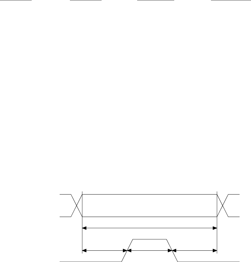
During the initial write of the DATA and ADDRESS lines, the STROBE line is
held low. After sufficient setup time, STROBE is driven high and then returns
low again. The minimum timing of this interface is reflected in figure 3-3.
Minimum Setup Time
200 nsec
Minimum Hold Time
200 nsec
Minimum Strobe High
200 nsec
Minimum Data Valid Time
600 nsec
ADDRESS,
DATA, and
ERROR Lines
STROBE
Line
FIGURE 3-4 DIGITAL OUTPUT TIMING DIAGRAM
If the received sensor input sample is detected to have no error’s present in
it, the ERROR line is driven low simultaneously with the DATA and ADDRESS
lines being set. If error’s are detected in the received sample, the ERROR
line will be driven high and the DATA lines will be driven to reflect the last
valid data sample for that analog channel. Other than start-up periods when
no valid samples are available, the Digital Telemetry Receiver will not output
invalid data samples onto the digital output port.
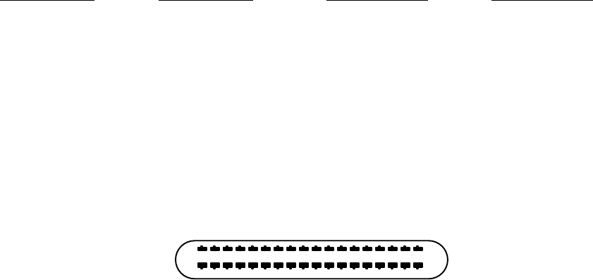
OM-06-320 REV E
- 25 - 99-500-001
It is important to note that the digital values reflected on this interface
contain the compensated and processed data content. Processing in this case
includes gain and offset adjustments required to satisfy the selected output
voltage range of the analog channel. Analog channels 2 through 18 have a
full-scale range of -10 VDC (represented by a digital value of 0x0000) to +10
Vdc (represented by 0xFFFF). If the customer specified receiver configuration
has limited the output voltage range to 0 to 5 VDC, output digital samples
will be limited to the range of 0x8000 to 0xBFFF. These values equate to 0
VDC (representing the minimum input sensor level) and 5 VDC (representing the
maximum input sensor level) respectively.
The following table supplies some typical output voltage range selections and
the corresponding minimum and maximum digital sample output values for each
setting.
TABLE 3-11 DIGITAL OUTPUT RANGES
MIN ANALOG VDC MAX ANALOG VDC MIN DIGITAL VAL MAX DIGITAL VAL
-10 +10 0x0000 0xFFFF
-5 +5 0x4000 0xBFFF
-2.5 +2.5 0x6000 0x9FFF
0 +5 0x8000 0xBFFF
0 +10 0x8000 0xFFFF
3.5.7 Analog Outputs
The optional analog outputs for channels 3 through 18 are provided via a 36
pin comb style connector (AMP part number 552742-1) located on the rear panel
and labeled “ANALOG”. This connector is not present for receiver systems
limited to 1 or 2 analog channels. As depicted in figure 3-4, the receiver
provides the female side of this connector and as such the user interface
cable must provide the male side (for example, SPC Technology Type 57-30360).
REAR PANEL VIEW
18 1
36 19
FIGURE 3-5 ANALOG OUTPUT CONNECTOR
Characteristics of these output analog signal are as shown in the following
table:
TABLE 3-12 ANALOG OUTPUT SIGNAL CHARACTERISTICS
FREQUENCY RESPONSE DC TO 10 KHz
VOLTAGE RANGE -10 to +10 VDC (USER SELECTABLE)
LOAD IMPEDANCE 1 KOHM MINIMUM
The pin assignments for this connector are as follows:

OM-06-320 REV E
- 26 - 99-500-001
TABLE 3-13 ANALOG OUTPUT PIN ASSIGNMENTS
PIN SIGNAL PIN SIGNAL PIN SIGNAL
1 ANALOG 3 7 ANALOG 9 13 ANALOG 15
2 ANALOG 4 8 ANALOG 10 14 ANALOG 16
3 ANALOG 5 9 ANALOG 11 15 ANALOG 17
4 ANALOG 6 10 ANALOG 12 16 ANALOG 18
5 ANALOG 7 11 ANALOG 13 17 +VREF (+10 VDC)
6 ANALOG 8 12 ANALOG 14 18 -VREF (-10 VDC)
19-36 GROUND
3.5.8 Channel 1 Analog
The analog channel 1 output is located on the front panel of the receiver and
is labeled “CHANNEL 1”. The connection for this interface is a standard BNC.
The receiver provides the female side of this connector and as such the user
interface cable must provide the male side.
Characteristics of this output analog signal are as shown in the following
table:
TABLE 3-14 ANALOG CHANNEL 1/2 SIGNAL CHARACTERISTICS
FREQUENCY RESPONSE DC TO 10 KHz
VOLTAGE RANGE 0 to +5 VDC
OUTPUT IMPEDANCE 1 KOHM MINIMUM
3.5.9 Channel 2 Analog
The analog channel 2 output is located on the front panel of the receiver and
is labeled “CHANNEL 2”. The connection for this interface is a standard BNC.
The receiver provides the female side of this connector and as such the user
interface cable must provide the male side. Characteristics of this output
analog signal are identical to those shown for analog channel 1.
3.5.10 Power On/Off Switch
The Power On/Off switch is a standard toggle switch located on the front panel
of the receiver with positions labeled for “ON” and “OFF” settings. Before
making any connections for the receiver, the user should insure this switch is
in an “OFF” position. Reference section 4 of this document for further
information on power on sequencing.

OM-06-320 REV E
- 27 - 99-500-001
3.5.11 Front Panel LED Indicators
There are four (4) front panel LED indicators on each receiver system. The
labels, colors, and meaning of each of these indicators is presented in the
following table.
TABLE 3-15 LED INDICATOR DESCRIPTIONS
LED LABEL “ON” COLOR DESCRIPTION
POWER GREEN When illuminated, indicates that the front panel power switch
is in an “ON” position and that valid 12 VDC power is
available at the rear panel “VDC” connection.
SYNC GREEN When off, indicates the system has not acquired frame synchronization
with the currently selected transmitter. When illuminated,
indicates that the system is properly receiving data from the selected
transmitter sufficient to achieve frame synchronization.
ERROR YELLOW Illuminated when an error is detected in the data contained within
a receive frame. Turned off when no errors are detected in a frame.
The error LED is also illuminated briefly during receive acquisition
processing if a valid signal is not detected within ~8 seconds.
This is utilized to inform the operator that the system is still
searching for a valid telemetry signal.
FAULT RED Illuminated when an internal fault condition is detected within
the receiver. A fault condition exists under the following possible
circumstances and will be reflected as indicated:
Self-Test Failure – ALL LED’s Illuminated
Invalid EEProm Table Content – or -
Invalid Transmitter Selected via Dip Switch – Fault LED Flashes 2 Times/Second
Internal RX Communications Failure – Fault LED Flashes once per second
Failure to Program Transmitter on Requested Change –
Fault LED Flashes every 2 Seconds
Note that all front panel LED’s also illuminate when the receiver is actively
being programmed via the remote serial port interface. This is not a failure
condition.
OM-06-320 REV E
- 28 - 99-500-001
SECTION 4 BASIC OPERATION
The Series 300 Digital Telemetry Product Line has been designed to provide a
user friendly interface environment while minimizing the amount of operator
interaction which must be taken to achieve proper measurement transmission
functions. In general, the system design is oriented towards a “hands-off”
philosophy while still supporting the necessary interfaces and capabilities to
allow detailed status and control of the unit if required for specific
applications.
The following paragraphs describe the procedures for verifying the basic
operation of the system and altering a limited number of system parameters.
Users should be aware that the Digital Telemetry System contains sensitive
electronic components. Proper “Electrostatic Discharge” (ESD) handling
procedures should be utilized for this equipment as with any other electronic
apparatus.
4.1 Getting Started
Each Series 300 delivery typically includes a set of 3.5 inch diskettes or a
CD ROM disk which includes control software for the system. Directions on the
diskette or CD ROM label should be followed to properly install this software
onto a personal computer (PC) operating with the Windows 95 or 98 operating
system. The installation procedure creates a program on the PC called
“Digital.exe” as well as associated data and support files to fully define the
purchased equipment. The “Digital.exe” program is also referred to as the
Digital Control Program within the context of this document
“Digital.exe” provides the interface from the PC to the Digital Telemetry
System. This software supports standard Windows type operation, including
menu based selection processes. Throughout the remaining portions of this
document, a reference such as “select aaaa : bbbb” indicates a Windows type
menu selection process where aaaa is the text name which appears at the top of
the active “Digital” program screen and bbbb is the submenu item displayed
once the aaaa menu is selected.
The Digital Control Program has been developed utilizing standard Windows
small fonts settings. Systems that deviate from these standard settings may
produce undesirable display results. If the program exhibits these
characteristics, locate the current display font settings by following the
Windows path for “Start : Settings : Control Panel : Display : Settings” and
insure small fonts is selected. Furthermore, the minimum Desktop Area setting
should be 800 by 600 pixels.
All of the screens associated with the Digital Control Program support online
help functions. This display of information can be activated by selecting
“Controls : Display Online Help Window” or “Controls : Display Online Help
Window”. By moving the mouse over the field of interest, the help window will
depict a description of any control or display field on the displays.
A set-up and introduction feature of the program provides a step by step
tutorial on how to connect the equipment, as well as validating various
operational parameters of the system as it is powered on and exercised through
a variety of processes.
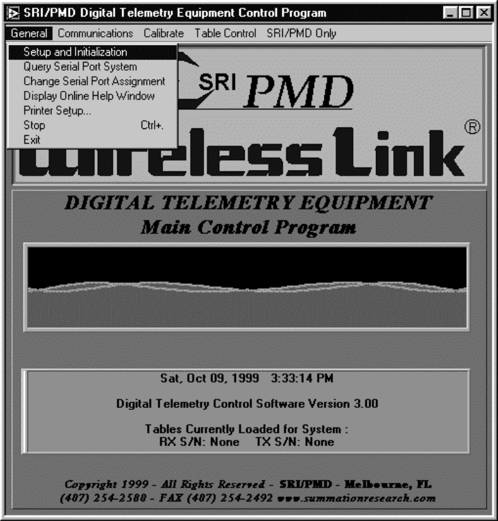
OM-06-320 REV E
- 29 - 99-500-001
To activate the set-up and introduction process, take the following steps:
1. Unpack and validate the contents of the shipping package.
2. Install the Digital Telemetry System Control Software on a PC as directed
on the label of the received diskettes or CD ROM.
3. Connect the Digital Telemetry Receiver to one of the PC’s serial ports via
a standard RS-232 serial port cable (9 pin D to 9 pin D). The cable should
connect to the “REMOTE” connection on the rear panel of the receiver. Note
that the factory delivered software assumes the use of the PC’s COM1: port,
but this may be altered during the set-up and introduction process.
4. Connect the AC to DC wall plug to the “VDC” input on the rear panel of the
receiver and then to an AC wall socket (110 VAC, 50 to 70 Hz). DO NOT
POWER ON THE RECEIVER AT THIS TIME.
5. Start the “Digital.exe” program on the PC from the installed program
directory.
6. Select “General : Set-up and Initialization”.
The following diagram shows the screen that will be displayed on the PC as
well as the selection action to start the set-up and initialization process.
FIGURE 4-1 DIGITAL CONTROL PROGRAM START-UP SCREEN
OM-06-320 REV E
- 30 - 99-500-001
All remaining steps for this procedure are given in easy to follow
instructions on the PC screen. The instructions include help suggestions in
case problems are detected during any given phase of the set-up process.
4.2 Stand-alone Validation of the Digital Telemetry System
Users without access to an appropriate PC can still monitor system start-up
processing with any equipment available that can display an ASCII text from an
RS-232 serial data stream. After making sure the front panel power switch is
in an “OFF” position, the user should connect the wall plug AC to DC converter
into the rear of the Digital Telemetry Receiver and then into a standard 110
VAC wall outlet. Next, a connection should be established from the “REMOTE”
connection on the rear panel to the equipment capable of displaying ASCII
text. The power switch may then be placed in the “ON” position.
During initial boot-up processing, the receiver executes a number of self-
tests and outputs results of this process on the “REMOTE” serial port on the
rear panel. The expected ASCII text for a successful system start-up will be:
TABLE 4-1 EXPECTED BOOT-UP ASCII TEXT
******************
RAM Test
Test Passed
ROM Test
Test Passed
ALU Test
Test Passed
RESPIC FW Version x.yy
EEPROM FW Version x.yy
Start-up Complete
******************
Within this text, the two (2) “x.yy” numbers will be replaced with text such
as “1.01”. These values indicate the firmware version number of key elements
of the receiver system. When requesting problem resolution assistance from
SRI/PMD, it is sometimes useful if these firmware version numbers are
available.
If start-up does not successfully complete, an error code will be reported
indicating what type of failure occurred. The following error codes have
currently been established for the Series 300 Digital Telemetry Receivers:
TABLE 4-2 SELF-TEST FAILURE CODES
10 Micro-Controller RAM failure
20 EEPROM failure (low byte of EEPCHECK1 location)
21 EEPROM failure (high byte of EEPCHECK1 location)
22 EEPROM failure (low byte of EEPCHECK2 location)
23 EEPROM failure (high byte of EEPCHECK2 location)
24 EEPROM failure (low byte of EEPCHECK3 location)
25 EEPROM failure (high byte of EEPCHECK3 location)
26 EEPROM failure (low byte of EEPCHECK4 location)
27 EEPROM failure (high byte of EEPCHECK4 location)
28 EEPROM failure (TDT first byte = 0)
29 EEPROM failure (TDT first byte = 0xFF)
30 ALU failure (Invalid Overflow on Increment)
31 ALU failure (Invalid non-Overflow on Increment)
32 ALU failure (Final result not zero)
33 ALU failure (Final result didn't carry)
OM-06-320 REV E
- 31 - 99-500-001
EEProm error codes (i.e., 20 through 29) can sometimes be corrected with a
reload of the EEProm memory space. This can be accomplished from a PC with
the appropriate support tools as discussed in a later section. All other
failures are indicative of a hardware failure, most likely requiring SRI/PMD
repair action.
If no equipment is available to monitor the ASCII stream, the operator is left
to rely on the front panel LED indicators. If after power-on, all indicators
illuminate and remain illuminated for more than 3 seconds, the system should
be returned to SRI/PMD for repair action. If the “FAULT” LED blinks but the
other LED’s are off, check the fault indications detailed at the end of
section 3 of this document for further clarification.
Assuming no failures, the front panel indicator should display power on
(“POWER” LED illuminated), no fault (“FAULT” LED off), and no system
synchronization (“SYNC” LED off). The “ERROR” LED may be intermittently
flashing on and off as noise is detected by the receive system.
Furthermore, if no Digital Telemetry Transmitter is present for data
reception, the system will periodically “reset” in order to restart system
acquisition. This occurs approximately every 8 seconds. The “reset” can be
detected on the front panel by the “ERROR” LED momentarily illuminating and
then returning to an off condition. This provides a simple means of knowing
that the system is operating and attempting to receive data from a Digital
Telemetry Transmitter.
At this point, the Digital Telemetry Transmitter can be activated. Paying
careful attention to the pinouts shown in appendix A of this document,
appropriate primary power should be applied to the transmitter.
If an antenna has been purchased with the Digital Telemetry System, it can now
be fastened to the “ANTENNA” connector on the receiver rear panel. Otherwise,
the operator should fasten the user-supplied antenna. Regardless, once this
has been accomplished, the front panel “SYNC” indicator should illuminate
within a maximum of 5 seconds. This indicates that the Digital Telemetry
Receiver has successfully recognized the output signal from the transmitter at
a sufficiently low error rate to achieve synchronization. In a close
proximity set up such as this, the “ERROR” LED should never illuminate, thus
indicating error free reception of the data.
If any of the above indications are not true, the user should validate proper
connections at all points in the set-up. Furthermore, if this is a newly
delivered system, the operator should validate that the DIP switches
accessible through the rear panel of the receiver are all turned to an OFF or
up position. Although they should be turned OFF by default from the factory,
shipment of the units may sometimes alter these settings. If all of the above
has been verified and the basic Digital Telemetry System communications test
still fails, SRI/PMD should be contacted for further assistance.
OM-06-320 REV E
- 32 - 99-500-001
4.3 Establishing Wireless Link Communications Settings
It is imperative that the settings for the Wireless Link operation be
optimized for each end-user application. To assist in this process, the
Digital Telemetry Control Program provides easy-to-use functions that monitor
and/or alter the characteristics of the link. The following paragraphs detail
the operation of this portion of the software.
4.3.1 Scanning the Available Communications Channels
In certain cases, select RF frequencies (or channels) may not be as robust as
others based on interfering signals or susceptibility to other external
elements. By default, each Series 300 Digital Telemetry System is delivered
from the factory set to a link frequency utilized for factory test. Based on
experimentation or data gathered from other sources, the operator may elect to
change the RF frequency to other available channels.
To assist in this process, the “Digital.exe” program provides an RF spectrum
analysis function. This process can be utilized to scan all available
communications frequencies and detect potential sources of interference.
To activate the RF spectrum analysis process, take the following steps:
1. Connect the antenna input that will be utilized during actual operation of
the system to the “ANTENNA” port on the rear panel of the Digital Telemetry
Receiver. DO NOT POWER ON ANY DIGITAL TELEMETRY TRANSMITTER DURING THIS
PROCESS. ALSO, INSURE POTENTIAL SOURCES OF INTERFERING SIGNALS WHICH WILL
NOT BE PRESENT DURING ACTUAL OPERATION ARE NOT ACTIVE.
2. Establish connections from the Digital Telemetry Receiver to the PC’s
serial port and to the VDC power input source. Power on the receiver.
3. Start the “Digital.exe” program on the PC from the installed program
directory.
4. Select “Communications : Scan Input RF Frequency Spectrum”.
Once activated, the available communications channels (or frequencies) will be
scanned and plotted on a graph. The user may leave this function running as
long as desired and the available channels will be repetitively scanned from
the lowest to the highest. The graph will depict both individual measurement
samples for the frequency as well as the cumulative averages as multiple
samples are accumulated.
Typically, the optimum frequency selection is the channel that exhibits the
lowest background noise level. Once a complete scan of the input spectrum has
been completed, the program indicates this channel by placing a red line at
that frequency setting. Some interpretation by the operator may be required
if channels of significant interfering signal levels surround the selected
lowest background noise channel.
When sufficient samples have been collected, the user may select “Controls :
Exit” to return to the main screen. During the exit procedure, the program
will report to the operator the exact frequency that indicated the lowest
level of background noise. Procedures discussed below can then be utilized to
change the frequency.
OM-06-320 REV E
- 33 - 99-500-001
4.3.2 Monitoring Online Communications Performance
The Digital Telemetry Control Software supports full real-time monitoring of
the communications link performance. This feature allows operators to
accurately assess signal levels and resulting communications error rates in
order to determine if the wireless link is providing acceptable measurement
transfer functions. Although ideally, the wireless link will provide error
free operation, in reality, any communications link is susceptible to periodic
errors.
To activate online communications performance analysis, take the following
steps:
1. Establish normal operation of the Digital Telemetry Receiver and
Transmitter and connections to the PC.
2. Start the “Digital.exe” program on the PC from the installed program
directory.
3. Select “Communications : Monitor Online Communications Performance”.
Once activated, a new screen will appear showing numeric fields on the left-
hand side and two (2) graphs on the right-hand side.
The numeric fields will indicate the number of digital telemetry data frames
received, how many of these frames had errors detected during the reception
process, and how many frames were considered lost due to poor reception
quality causing the system to activate the acquisition process. Numeric
values are provided for the last sample period (approximately 1 second) as
well as cumulative figures since the start of the monitoring process.
The graphs depict the resulting frame error rate and estimated input signal
level. The frame error rate is calculated as (frames in error)/(frames
received). Lost frames are not considered in the error rate calculation.
Both cumulative and per sample plots are provided. The input signal level
provides an estimate of the signal plus noise level of the input signal
expressed in dBm. Again, both cumulative and per sample plots are provided.
A data frame is approximately 32 sensor sample periods long. Any frames in
error result in the loss of 32 consecutive sensor samples. Although ideally
no frames in error will ever be detected, some installations can accept a
certain error rate as long as sufficient data is being recovered to support
accurate analysis functions.
Pertaining to signal levels, typically any reading above –70 dBm is considered
a high quality signal, although reception can typically be to as low as –85
dBm input level. These figures are not absolute in that the reported signal
level reflects signal AND noise, where noise can be any external interfering
signals or simply background thermal noise. As such, reported signal levels
as high as 0 dBm may still yield no usable data if signals or noise other than
the desired wireless link telemetry signal is driving the input level.
Select “Controls : Exit” to return to the main selection screen.
4.3.3 Changing the Communications Settings
If either online monitoring of the communications performance or the RF
spectrum scan dictate a need for changing the current communications settings,
the Digital Telemetry Control Program provides the means to accomplish this
task.
OM-06-320 REV E
- 34 - 99-500-001
To modify either the current frequency or transmission baud rate selection of
the Digital Telemetry System, take the following steps:
1. Establish normal connections between the Digital Telemetry Receiver and the
PC.
2. Changes to baud rate or frequency settings require modifications to EEProm
space in both the Receiver and the Transmitter. As such, the Digital
Telemetry Transmitter must be connected to the Receiver via the special
Programming Interface Cable supplied with the system. To accomplish this
connection, perform the following steps:
a. Turn off power to the Digital Telemetry Receiver.
b. Connect the Programming Interface Cable to the DIN connector on the rear
panel of the receiver labeled “PROGRAM”.
c. Turn off power to the Digital Telemetry Transmitter.
d. Connect the other end of the Programming Interface Cable to the 5 pin
Programming Interface Connection on the Transmitter, insuring proper pin
1 alignment.
e. Restore power to the Digital Telemetry Receiver.
NOTE – if the green POWER LED on the receiver front panel does not
illuminate, immediately turn off power and validate the Programming
Interface Cable connection. During programming operations, the receiver
provides power to the transmitter, but if the cable connection to the
transmitter is reversed, a short condition will be introduced to the
receiver and the POWER LED will not illuminate. Introducing a short
condition to the equipment can cause damage to the electronic components of
the system.
3. Start the “Digital.exe” program on the PC from the installed program
directory.
4. Select “Communications : Change Frequency and/or Baud Rate”.
Once activated, a new screen will appear showing the current frequency and
baud rate selections. By clicking and holding on the arrow next to the
current settings, the user can access menu’s showing all supported settings of
these parameters. Select the desired setting and then release the mouse
button.
The actual change does not go into affect until the user selects “Controls :
Set New Frequency/Data Rate”. Once activated, the system will download the
new information to the Digital Telemetry Receiver and will the reprogram the
Digital Telemetry Transmitter via the Programming Interface Cable.
When all changes have been accomplished, remove power from the Digital
Telemetry Receiver, disconnect the Programming Interface Cable, and return the
Digital Telemetry Transmitter to it’s normal operational connections. Select
“Controls : Exit” to return to the main selection screen.
In general, reductions in link baud rate will improve the communications link
performance by reducing the number of frame error’s encountered. Conversely,
higher link baud rates provide faster sensor sampling rates and the cost of
potentially higher susceptibility to link errors.
Some miniaturized Digital Telemetry Transmitters (e.g., ST-364) do not support
a programming interface. For these systems, the transmit frequency is
established via a fixed set resistor across two (2) pins on the transmit
module. In this case, a change in the resistor value still requires a change
in the expected receive frequency. All steps indicated above should be
followed with the exception of any dealing with the programming interface
OM-06-320 REV E
- 35 - 99-500-001
cable. The software will warn the operator that the changes will only affect
the receiver and transmit frequency must be accomplished via the resistor
change.
For users with multiple receivers supporting the same transmitters, it is
imperative that changes in communications settings invoked through one (1)
receiver are also reflected into any additional receivers. Follow the
instruction indicated in the following section to achieve this transfer of
information to each additional receiver system.
4.4 Loading/Restoring Configuration Tables/Software
The Digital Telemetry Control Program can also be utilized to restore or
upgrade new configuration tables into the Digital Telemetry System. There are
a multitude of reasons for taking this action as follows.
SRI/PMD may send new Configuration Tables periodically either via diskette or
electronic connections. These updates may be issued under the following
circumstances:
1)
The customer has purchased a new transmitter and wishes to utilize it with
an existing Digital Telemetry Receiver, or
2)
The customer has requested an alteration to the current configuration of an
existing transmitter or receiver.
For users with multiple receivers supporting the same transmitters, changes to
configuration information (such as frequency, baud rate, calibration data, and
so forth) in one receiver must be carried over to all other receivers.
Finally, although configuration tables are stored in non-volatile EEProm
memory space in both the receiver and the transmitter, operation in severe
environments or with noisy power supply systems can sometimes corrupt these
tables.
After insuring that the correct files are on the PC being utilized, or in the
case of new configuration files, insuring that the files are copied into the
install directory, the information must be loaded into the Digital Telemetry
Receiver to activate the configuration information. In order to update all of
the EEProm tables within the receiver from the PC, the following steps should
be taken:
1. Establish normal connections between the Digital Telemetry Receiver and the
PC.
2. Start the “Digital.exe” program on the PC from the installed program
directory.
3. Select “Table Control : Download : Receiver and Transmitter Definition
Table Space”.
This action will activate a screen indicating the progress of the download
process. After the download has completed, the main screen will return.
The same EEProm memory space that contains the configuration tables also
includes the executable code for the main micro-controller within the
receiver. This not only allows for restoring the executable code in case it
becomes corrupted for some reason, but also supports field upgrades of the
receiver executable code. Each release of the Digital Telemetry Control
Program includes an embedded copy of the latest receiver micro-controller
OM-06-320 REV E
- 36 - 99-500-001
executable code thus enabling users to upgrade existing fielded systems
whenever new control software is installed on the PC.
To restore or update the receiver executable code, follow the same process
outlined above but at step 3, select “Table Control : Download : Receiver
MicroController Executable Code”. This action will activate a screen
indicating the progress of the download process. After the download has
completed, the main screen will return.
4.5 Changing Transmitter Versions
As previously indicated, any given transmitter may be configured for different
sensor or digital telemetry configurations.
In order to change the active version of any given transmitter, take the
following steps:
1. Establish normal connections between the Digital Telemetry Receiver and the
PC.
2. The Digital Telemetry Transmitter must be connected to the Receiver via the
special Programming Interface Cable supplied with the system. To
accomplish this connection, perform the following steps:
a. Turn off power to the Digital Telemetry Receiver.
b. Connect the Programming Interface Cable to the DIN connector on the rear
panel of the receiver labeled “PROGRAM”.
c. Turn off power to the Digital Telemetry Transmitter.
d. Connect the other end of the Programming Interface Cable to the 5 pin
Programming Interface Connection on the Transmitter, insuring proper pin
1 alignment.
e. Restore power to the Digital Telemetry Receiver.
NOTE – if the green POWER LED on the receiver front panel does not
illuminate, immediately turn off power and validate the Programming
Interface Cable connection. During programming operations, the receiver
provides power to the transmitter, but if the cable connection to the
transmitter is reversed, a short condition will be introduced to the
receiver and the POWER LED will not illuminate. Introducing a short
condition to the equipment can cause damage to the electronic components of
the system.
3. Start the “Digital.exe” program on the PC from the installed program
directory.
4. Select “Table Control : Download : Transmitter Definition via Programming
Cable”.
5. From the list provided, select the desired version number of the
transmitter by double clicking on the line item.
The system will program the transmitter to the new version information and
then respond with a completion message. After the update has completed,
select “OK” to return to the main screen.
Note that each different transmitter version is treated as unique transmitter
by the system. As such, once the transmitter configuration has been altered,
the Digital Telemetry Receiver must be configured to expect data from the new
version. Reference the following section for the procedure to change the
selection of the receiver to the new transmitter version.
OM-06-320 REV E
- 37 - 99-500-001
4.6 Interfacing to Different Transmitters
Each Digital Telemetry Receiver may be configured to interface with up to 16
unique transmitters or different versions of the same transmitter. As new
transmitters are added to a receiver’s capability, the specific serial number
of the transmitter is assigned a receiver transmit index code ranging from 0
to 15. The transmit index code of available transmitters can be viewed via
utilization of the Digital Telemetry Control Program as follows:
1. Establish normal connections between the Digital Telemetry Receiver and the
PC.
2. Start the “Digital.exe” program on the PC from the installed program
directory.
3. Select “General : Query Serial Port System”.
The resulting display will depict what transmitter serial numbers and versions
the current receiver is compatible with receiving data from. The first
transmitter shown corresponds to a transmitter index selection of 0, the
second corresponds to 1, and so forth through a possible maximum index of 15.
On the rear panel of the Receiver, four (4) DIP switches previously defined in
section 3 of this document select which of the transmit index codes should be
utilized. These switch settings may be altered at any time during normal
operation and the system will automatically reconfigure itself for the new
setting.
If the operator selects a transmit index that is not assigned for this
receiver, the front panel “FAULT” light will illuminate indicating an invalid
selection. This indicator will turn off once a valid transmitter setting is
established.
The transmitter index selection may also be altered via serial port commands
through the remote control interface. Reference later paragraphs of this
section for more information on this capability.
4.7 System Shut-Down
In order to shutdown the Digital Telemetry Receiver, simply place the two (2)
position power switch into the “OFF” position. The front panel power LED
should immediately turn off indicating shut down completion. Exercising
prudent care of electronic equipment, a power-on sequence from the front panel
should not be attempted for five (5) seconds after a system shutdown.
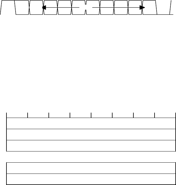
OM-06-320 REV E
- 38 - 99-500-001
SECTION 5 REMOTE STATUS/CONTROL
The remote status/control interface supports control and status functions for
the Digital Telemetry Receiver across the “REMOTE” RS-232 interface located on
the rear panel. The following paragraphs describe the protocol associated
with this interface.
5.1 Remote Interface Frame Format
The remote status/control interface is an asynchronous RS-232 link capable of
operating at rates up to 19200 bps and can support even, odd, or no parity.
As shown in Figure 4-1, each data byte is transferred asynchronously, least
significant bit first, and is surrounded by one (1) start bit, one (1) stop
bit, and one (1) parity bit (when parity is used). The default operating
parameters for the interface is 9600 bps, 1 start bit, 1 stop bit, and no
parity. Additional interface characteristics are available upon request.
DATA LSbMSb
Opt
PARITY
STOP START
bit 10 bit 9 bit 8 bit 7 bit 6 bit 5 bit 4 bit 3 bit 2 bit 1 bit 0 bit 0
FIGURE 5-1 REMOTE STATUS/CONTROL BYTE FORMAT
The interface is a byte oriented bus (eight (8) bits). Bytes are grouped
together to form frames which constitute an entire message. All transfers are
accomplished starting with byte 0 and ending with the last byte of the frame
(frame checksum).
Frame formats are the same for both sides of the interface (i.e., input and/or
output to the Digital Telemetry Receiver). All frames are composed of three
(3) fields as shown in Figure 4-2.
b7 b6 b5 b4 b3 b2 b1 b0
BYTE
0
FRAME BYTE COUNT
FIELD
BYTE
1
FIRST BYTE OF
DATA FIELD
BYTE
2
SECOND BYTE OF
DATA FIELD
...
...
BYTE
N-1
LAST BYTE OF
DATA FIELD
BYTE
N
FRAME CHECKSUM
FIELD
FIGURE 5-2 REMOTE STATUS/CONTROL FRAME FORMAT
The byte count field contains a count of the total number of bytes in the
frame, including the byte count field.

OM-06-320 REV E
- 39 - 99-500-001
The data field bytes contain the commands on the input side of the receiver
and provide the status on the output side from the receiver. Section 4.2.2
below describes the contents of this field.
A frame checksum field is included on all frames and is used to verify that no
errors occurred during the frame transfer. The checksum is calculated by
performing a two’s compliment addition of all frame bytes preceding the
checksum field, truncating the result to eight (8) bits, and performing a
two's complement negate of the result. On the receive side, the checksum is
verified by adding all bytes together including the checksum byte and
verifying that the result is zero (0). The parity, start, and stop bits are
not included when calculating the frame checksum.
When a command is received, the receiver validates the byte count and
checksum, and then attempts to process the command, invoke any necessary
configuration changes, and respond with an appropriate status message.
Invalid byte counts, checksums, or data field parameters result in a negative
acknowledgment. In order to accommodate this entire process, a minimum three
(3) second time-out waiting for response should be incorporated after any
command is issued to the receiver.
5.2 Data Field Contents
The data field of the remote status/control frame contains the commands to be
performed by the Digital Telemetry Receiver or the response in return from
these commands. The following sections describe the contents of the data
field for each message type. Please note that byte offsets shown in the
following paragraphs indicate offsets within the data field as opposed to
frame offsets.
5.2.1 Set Configuration Command
The set configuration command is used to establish the operating parameters of
the Digital Telemetry Receiver. This command will override the current
settings of the rear panel DIP switches until such time as the system
experiences a power up restart. Figure 4-3 depicts this command format.
BYTE
0
COMMAND FIELD
(0)
BYTE
1
TRANSMITTER INDEX
SELECT
BYTE
2
DO NOT
USE
BYTE
3
DO NOT
USE
FIGURE 5-3 SET CONFIGURATION COMMAND FORMAT
Fields contained within this command are defined in the following table.

OM-06-320 REV E
- 40 - 99-500-001
TABLE 5-1 SET CONFIGURATION COMMAND PARAMETERS
FIELD DEFINITION
COMMAND FIELD VALUE OF 0 INDICATING A SET CONFIGURATION COMMAND
TX INDEX SELECT BIT 7 CONTROLS WHETHER THE COMMAND SHOULD RESULT IN A DOWNLOAD OF THE
TRANSMITTER DEFINITION TO THE TRANSMITTER VIA THE PROGRAMMING INTERFACE CABLE
(1) OR NOT (0).
BIT 6 CONTROLS WHETHER A NEW TRANSMITTER INDEX IS BEING SELECTED BY THE
COMMAND (1) OR WHETHER THE CURRENTLY ACTIVE RECEIVER TRANSMITTER INDEX SHOULD
BE USED (0).
THE LOW ORDER 4 BITS SELECT A VALUE BETWEEN 0 AND 15 TO SPECIFY A NEW
TRANSMITTER INDEX SETTING FOR THE RECEIVER.
IF BIT 7 IS SET AND THE RECEIVER DOES NOT DETECT THE PRESENCE OF A
TRANSMITTER ON THE PROGRAMMING INTERFACE CABLE, A NEGATIVE ACKNOWLEDGEMENT
WILL RESULT.
IF BIT 6 IS SET AND THE RECEIVER DOES NOT HAVE A CORRESPONDING TRANSMITTER
DEFINED FOR THE SELECTED INDEX, THE COMMAND WILL RESULT IN A NEGATIVE
ACKNOWLEDGEMENT. OTHERWISE, THE SYSTEM WILL BEGIN ATTEMPTING TO ACQUIRE A
TRANSMISSION FOR THE NEW TRANSMITTER.
ALL OTHER VALUES ARE INVALID
DO NOT USE THESE FIELDS MUST BE SET TO 0 FOR PROPER OPERATION OF THE COMMAND.
5.2.2 Report Status Command
The report status command is used to request a status response from the
Digital Telemetry Receiver. Figure 4-4 depicts this command format.
BYTE
0
COMMAND FIELD
(255)
FIGURE 5-4 REPORT STATUS COMMAND FORMAT
The command field is simply set to a value of 255 to invoke this command. The
command causes the receiver to respond with a status response without changing
any operational parameters.
5.2.3 Read Analog Channel Command
The read analog channel command causes the Digital Telemetry Receiver to
respond with the last valid output value for any given analog channel. The
following figure depicts the format of this command.
BYTE
0
COMMAND FIELD
(1)
BYTE
1
ANALOG CHANNEL
SELECT
FIGURE 5-6 READ ANALOG CHANNEL COMMAND FORMAT

OM-06-320 REV E
- 41 - 99-500-001
The command field is simply set to a value of 1 to invoke this command. The
analog channel select is a value between 0 and 17 corresponding to analog
channels 1 through 18. All other values are invalid in this field.
5.2.4 System Status Response
The system status response is returned from the Digital Telemetry Receiver at
the completion of successfully processing any command with the exception of
the read analog channel command. The following figure depicts the format of
this response.
BYTE
0
STATUS RESPONSE
(0)
BYTE
1
BACK-END
STATUS
BYTE
2
FRONT-END
STATUS
BYTE
3
TRANSMITTER SERIAL NUMBER
(HIGH BYTE)
BYTE
4
TRANSMITTER SERIAL NUMBER
(LOW BYTE)
BYTE
5
RECEIVE STRENGTH
SIGNAL INDICATOR
BYTE
6
TRANSMITTER OPERATIONAL
TEMPERATURE MEASUREMENT
FIGURE 5-7 STATUS RESPONSE FORMAT
The status response field of 0 simply indicates the message type. Bytes 1
through 8 are defined as follows:
TABLE 5-2 STATUS RESPONSE PARAMETERS
FIELD DEFINITION
BACK-END STATUS VALUE INDICATING THE CURRENT STATUS OF THE BACK-END MICRO-CONTROLLER OF
THE DIGITAL TELEMETRY RECEIVER:
Bit 7 indicates the system sync status as in-sync (1) or out of sync (0).
Bit 6 indicates the last received frame had an error (1) or was error free
(0).
Bit 5 indicates the system has detected an error in the configuration
tables (1) or not (0).
Bit 4 indicates the back-end micro-controller has encountered errors in
communicating with the front-end micro-controller (1) or not (0).
Bit 3 indicates the last attempt to program a new transmitter frequency
either because of a remote command or due to dip switch settings failed
(1) or was successful (0).
ALL OTHER BITS ARE RESERVED.

OM-06-320 REV E
- 42 - 99-500-001
FRONT-END STATUS VALUE INDICATING THE STATUS OF THE FRONT-END MICRO-CONTROLLER OF THE
DIGITAL TELEMETRY RECEIVER:
Bit 4 indicates the last received frame had a frame-sync error (1) or not
(0).
Bit 3 indicates the last received frame had a check-sum error (1) or not
(0).
Bit 2 indicates the last received byte had an data overrun error (1) or
not (0).
Bit 1 indicates the last received byte had a framing error (1) or not (0).
Bit 0 indicates the front-end micro-controller is in-sync with the
incoming signal (1) or attempting to acquire synchronization (0).
ALL OTHER VALUES ARE INVALID.
TRANSMITTER SERIAL
NUMBER (HIGH BYTE) BITS 15 (MSB) THROUGH 8 (LSB) OF THE SERIAL NUMBER OF THE TRANSMITTER
WHICH THE RECEIVER IS CURRENTLY CONFIGURED TO COMMUNICATE WITH.
TRANSMITTER SERIAL
NUMBER (LOW BYTE) BITS 7 (MSB) THROUGH 0 (LSB) OF THE SERIAL NUMBER OF THE TRANSMITTER WHICH
THE RECEIVER IS CURRENTLY CONFIGURED TO COMMUNICATE WITH.
RECEIVED STRENGTH
SIGNAL INDICATOR CURRENT VALUE (0 TO 255) OF THE RECEIVE STRENGTH SIGNAL INDICATOR.
TX OPERATIONAL
TEMPERATURE MEASURE CURRENT VALUE (0 TO 255) OF THE LAST RECEIVED TRANSMITTER OPERATIONAL
TEMPERATURE MEASUREMENT. VALUE REFLECTS CENTIGRADE TEMPERATURE OF
TRANSMITTER IN 0.5 DEGREE INCREMENTS.
5.2.5 Analog Channel Value Response
The analog channel value response is returned from the receiver whenever a
valid read analog channel command is received. The following figure depicts
the format of this response.
BYTE
0
ANALOG CHANNEL VALUE RESPONSE
(1)
BYTE
1
ANALOG CHANNEL VALUE
HIGH BYTE
BYTE
2
ANALOG CHANNEL VALUE
LOW BYTE
FIGURE 5-8 ANALOG CHANNEL VALUE RESPONSE FORMAT
The byte 0 value of 1 indicates it is an analog channel value response. The
remaining two (2) bytes form a 16 bit number which reflects the last output
value for the analog channel. Refer to the section 3 paragraph on digital
outputs for further information on the formatting of this number.
5.2.6 Negative Acknowledgment Response
The negative acknowledgment response is returned from the receiver whenever
problems are encountered in processing any command. Figure 4-6 depicts the
format of this response.
BYTE
0
NAK RESPONSE
(NEGATIVE NUMBER)
FIGURE 5-9 NEGATIVE ACKNOWLEDGMENT RESPONSE FORMAT
OM-06-320 REV E
- 43 - 99-500-001
Any negative byte 0 value (i.e., bit 7 = 1) indicates a negative
acknowledgment response. The actual value in these cases indicates why the
received command was considered invalid as follows:
TABLE 5-3 NEGATIVE ACKNOWLEDGEMENT CODES
-1 Byte level parity error occurred.
-2 Invalid command word received.
-4 Invalid byte count field received.
-5 Unexpected communications error occurred.
-6 Message checksum error.
-7 Data overrun error on incoming message.
-8 Byte framing error occurred (i.e., invalid start/stop bits).
-10 Entire message not received within timeout period.
-16 Undefined transmitter index selected on a configuration control command.
-17 No transmitter connected to programming cable on a download transmitter
configuration command.
-18 Wrong transmitter connected to programming cable on a download transmitter
configuration command.
-19 Invalid analog channel selected for read command.
The Digital Telemetry Receiver takes no action on any command received which
results in a negative acknowledgment.
OM-06-320 REV E
- 44 - 99-500-001
SECTION 6 SYSTEM CALIBRATION
A key to successful utilization of the Digital Telemetry System is to insure
that given sensor input stimuli result in known and accurate output analog
values on the receiver. This process requires that the system is programmed
for the correct offset and gain settings as previously discussed in section 3
of this document.
Although all Series 300 Products are calibrated at the factory to establish
the initial gain and offset settings, periodic adjustments may be required to
these values due to equipment aging and/or gain/offset errors introduced by
end-user installation or sensor selection. Fortunately, the Digital Telemetry
Control Software provides a simple means of performing this calibration
process.
6.1 Calibration Set-up
System calibration requires that the operator can establish a minimum of two
(2) known stimuli conditions for any given sensor input to the Digital
Telemetry System. The “known” setting may be the defined minimum and maximum
measurement values to the system, or any level in-between. Regardless, the
accuracy of the calibration process will be established by the accuracy of
this stimulus setting.
Suppliers of sensors typically provide a means of establishing these known
conditions. Examples of this capability include shunt calibration resistors
for balanced bridge strain or pressure gages, simulators for thermocouples, or
accurate voltage references for general purpose sensors.
During system calibration, the user should attempt to establish conditions for
the Digital Telemetry System as close to the actual end application
environment as possible. This includes such parameters as the mounting of the
Digital Telemetry Transmitter, location of the receive antenna with respect to
the transmitter, utilizing the actual transmitter power source (battery,
generator, ...) which will be utilized during the telemetry process, and so
forth.
In addition, some systems require what is referred to as temperature based
calibration. In these cases, the gain and offsets will vary within the system
based on the current reported operational temperature of the transmitter. In
order to accomplish temperature based calibration, the user must be able to
establish a minimum of two (2) known stimuli conditions on each sensor input
at a minimum of two (2) transmitter operating temperatures. This implies a
means of controlling the ambient temperature of the transmitter either via use
of a thermal chamber or some other temperature control means.
For systems only operating within a limited operating temperature range,
temperature based calibration may not be required. Typically, balanced bridge
measurements limited to the industrial temp range (i.e., 0 to 85° C) can
bypass this feature.
In thermocouple applications, the transmitter is frequently utilized as the
“zero junction reference box” for the sensor. In this case, temperature based
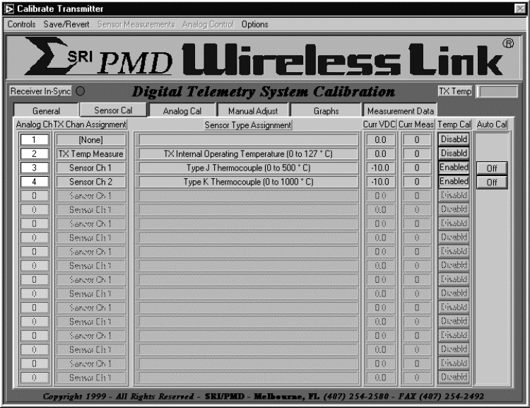
OM-06-320 REV E
- 45 - 99-500-001
calibration is recommended, unless the accuracy requirements of the end-user
data can tolerate these offsets.
6.2 Computer Assisted System Calibration
The following paragraphs describe how to utilize the PC and the “Digital.exe”
software to calibrate a Digital Telemetry System.
6.2.1 Starting the Calibration Function
Once the operator has established the system configuration and test equipment
as described above, the calibration process can be started from the Digital
Telemetry Control Software as follows:
1. Establish normal connections between the Digital Telemetry Receiver and the
PC and active wireless link operation between the transmitter and the
receiver.
2. Start the “Digital.exe” program on the PC from the installed program
directory.
3. Select “Calibrate : Calibrate Telemetry System”.
This action will result in a screen being displayed as depicted in the
following example with several tabs along the top for selecting different
screens of display information.
FIGURE 6-1 SAMPLE CALIBRATION DISPLAY SCREEN
OM-06-320 REV E
- 46 - 99-500-001
The “General” tab selects the display to general information about the
telemetry system connected to the serial port including serial numbers,
descriptions, last calibration date, and so forth. There are no controls for
this screen.
The “Sensor Cal” tab selects the display to a table with each of the defined
analog channels shown as well as:
a) the channels associated transmitter sensor assignment,
b) the sensor type and measurement range, and
c) the current reading for the channel presented both as the analog
channel output VDC level and the corresponding sensor measurement
levels.
The indicated levels are only valid if the system is receiving data from the
selected transmitter. The controls on the right hand side of the screen are
utilized to calibrate the sensor channel as indicated below.
The “Analog Cal” tab also selects the display to a table with each of the
defined analog channels, but depicts active data filtering and selected output
VDC ranges as opposed to the sensor information indicated above. The control
on the right hand side of the screen is utilized to calibrate the analog
channel as indicated below.
The “Manual Adjust” tab selects the display to detailed information about
sensor calibration gain and offset settings for a particular analog/sensor
channel. The channel selection is located at the top of the screen while the
detailed data fills the remaining portion of the screen. If temperature based
calibration is enabled for the selected channel, then the detailed data
includes gain and offset settings for all temperatures from 0 to 126°C in 2°C
increments. If temperature based calibration is not enabled, the gain/offset
adjust data is limited to a single setting. This screen can be utilized for
manual adjustment to the calibration data as described below.
The “Graphs” tab selects the display to three (3) graphs which correlate to
current sensor channel measurement data, gain adjust curve, and offset adjust
curve. As with the “Manual Adjust” screen, the channel selection for the
graphs is located at the top of the screen while the graphs fill the remaining
portion of the screen.
The “Measurement Data” tab selects a screen allowing the operator to view
measurements that have been made during the computer assisted calibration
process as discussed below. Measurement information shown includes the
transmitter temperature at the time of the measurement, the desired output
analog voltage, as well as the actual output analog voltage.
6.2.2 Calibrating Sensor Channels
At the far right-hand side of the “Auto Cal” screen is a column also labeled
“Auto Cal” with control buttons initially showing an “OFF” condition. This
indicates calibration is not active for any channel. The column next to this
is labeled “Temp Cal” and will show “Enabled” if temperature based calibration
is enabled for the channel or “Disabld” if it is not enabled. Before starting
calibration, the “Temp Cal” selection should be verified and/or changed to the
correct setting for each channel. This is accomplished by placing the cursor
OM-06-320 REV E
- 47 - 99-500-001
over the corresponding “Temp Cal” button and doing a left hand click to toggle
the setting..
To activate a computer assisted calibration process on an individual channel,
the operator should click on the “Auto Cal” button corresponding to that
particular channel. This will change the state of this control to an “ON”
condition. If the transmitter definition includes multiple sensor channels
with the exact same definition AND if the set-up described above will support
driving multiple channels at the same time, the operator may activate
calibration on multiple channels at the same time. To enable this capability,
select “Options : Enable Multi-Channel Calibration” which then allows
multiple, identically defined sensor channel “Auto Cal” controls to be turned
“ON”.
To perform the calibration process on the channel or channels, execute the
following steps:
1. Establish a known stimuli condition for the corresponding sensor for this
channel. Also establish a stable transmitter operating temperature if
temperature based calibration has been invoked. A stable operating
temperature can be detected by a non-changing value on the reported
temperature status indicator near the top of the calibration screen.
2. Invoke a measurement on the sensor channel by selecting “Sensor
Measurements : Sensor(s) is at xxxx” where xxxx will be replaced with the
text corresponding to one (1) or five (5) measurement points. These points
will be dependent upon the defined sensor type, total measurement range,
and measurement units and will correspond to 0, 25, 50, 75, and 100% of the
measurement range for unipolar (i.e., positive only) sensor definitions, or
–100, -50, 0, 50 and 100% of the measurement range for bipolar(i.e.,
positive and negative) sensor definitions.
For instance, a strain gage defined to measure –200 to +200 micro-strain
will depict the following measurement options:
a. Sensor is at –200 uE
b. Sensor is at –100 uE
c. Sensor is at 0 uE
d. Sensor is at 100 uE
e. Sensor is at 200 uE
Similarly, a thermocouple defined to measure 0 to 500° C will depict the
following measurement options:
a. Sensor is at 0
°
°°
°
C
b. Sensor is at 125
°
°°
°
C
c. Sensor is at 250
°
°°
°
C
d. Sensor is at 375
°
°°
°
C
e. Sensor is at 500
°
°°
°
C
For stimuli conditions not covered by the fixed selections described above,
the operator may choose one of the following options:
a. Select “Sensor Measurements : Channel is at User Specified Level :
Specified as Sensor Input Measurement Level”. This will activate an
additional screen where the operator may enter a value between the
minimum and maximum defined valid sensor measurement units for the
active channel (e.g., +225° C or –93 uE).
b. Select “Sensor Measurements : Channel is at User Specified Level :
Specified as Percentage of Measurement Range”. This will activate an
additional screen where the operator may enter between 0.00 and
OM-06-320 REV E
- 48 - 99-500-001
100.00 percent for unipolar values or between –100.00 to +100.00
percent for bipolar values. For instance, a strain gage configured
for +/- 500 micro-stain strain with a stimuli of –250 uE should
result in a selected measurement percentage of –50%.
c. Select “Sensor Measurements : Channel is at User Specified Level :
Specified as Desired Analog Output Voltage Level”. This will activate
an additional screen where the operator selects an actual VDC output
level the analog channel should be at for the current sensor stimuli.
With the same example as above on an analog channel configured for
+/- 10 VDC output, the selection should be for –5.00 VDC.
3. After establishing the appropriate selection, the system will indicate that
a measurement is active on the analog channel. After the measurement has
completed, the “Auto Cal” control for each “ON” channel will turn yellow to
indicate that a measurement has been made, but insufficient information
exists to calibrate the channel. To validate the measurement, the operator
may select the “Measurements” tab and view the results.
4. Repeat steps 1 and 2 for a different input stimulus. After this has
completed, the number of measurements made as shown on the “Measurements”
tab display should reflect 2. Furthermore, if temperature based
calibration is not enabled, the “Auto Cal” control for each “ON” channel
will turn green, indicating successful initial calibration.
5. If temperature based calibration is enabled, repeat the above process for a
different stable transmitter operating temperature. For this case, once 4
measurements have been made (2 each at 2 discrete temperatures), the “Auto
Cal” control for each “ON” channel will turn green.
Additional measurements beyond the 2 or 4 discussed above can be activated
which will improve the accuracy of the calibration process.
If an error is made in the setting of the stimuli or the selection of the
measurement function, the operator may either:
a) Delete individual measurements that are in error. This is accomplished by
selecting the “Measurements” tab display, locating the erroneous
measurement, and then selecting the “Ignore this Measurement Point” control
to “Point Disabled”.
b) Select “Save/Revert : Revert to Last Stored in Receiver EEProm”. This
action will discard all measurement data and calibration information from
the current calibration session and reload the gain/offset tables from the
receiver EEProm memory space.
c) Select “Save/Revert : Revert to Factory Settings”. This action will reset
the calibration and configuration data for the active transmitter and
receiver to the “as-delivered” factory settings. Any calibration changes
done since the transmitter was delivered from SRI/PMD will be discarded.
The calibration and measurement process outlined above only updates
calibration data within the PC’s local memory. Once the operator is satisfied
with the calibration data for the channel, “Save/Revert : Update Receiver
Calibration Data” should be selected. This will update both the receiver non-
volatile storage space as well as the PC resident disk files associated with
the transmitter. Note that multiple sensor channels can be calibrated prior
to storing the values within receiver EEProm memory space if the operator so
desires. Turning the “Auto Cal” control “OFF” on a previously calibrated
channel does not lose the calibration data associated with that channel.
OM-06-320 REV E
- 49 - 99-500-001
6.3 Manual Adjustments to Calibration Data
For users lacking the capability to perform the Computer Assisted Calibration
process discussed above, manual alteration of the calibration data is
possible. To invoke this procedure, activate the “Manual Adjust” tab from the
calibration program screen. Note that for manual adjustments to the
calibration data, the “Auto Cal” controls for the channel in question must be
set to “OFF”
For channels with temperature based calibration disabled, the single
gain/offset adjustment value will be displayed for the analog channel selected
via the control located at the top of the display. Utilizing the up/down
arrows located next to the gain adjust and offset adjust values, the operator
may raise or lower the values. Alternatively, standard text entry methods may
be utilized to change the settings.
Since gain is a multiplicative function, the nominal control setting for
adjusting gain is 1.000. Gain can be decreased by taking this value below the
nominal or increased by taking it above the nominal. Offset is an additive
function and, as such, the nominal control setting for this adjustment is 0.
For channels invoking temperature-based calibration, all temperature point
gain and offset values will be displayed. In addition, a “Common Adjust All
Gains” and “Common Adjust All Offsets” will be displayed. These controls
provide an easy means of shifting the entire gain or offset curves by common
amounts. In addition, individual temperature points may be adjusted as
discussed above.
As with computer assisted calibration, the manual process outlined above only
updates calibration data within the PC’s local memory. Once the operator is
satisfied with the calibration data for the channel, “Save/Revert : Update
Receiver Calibration Data” should be selected. This will update both the
receiver non-volatile storage space as well as the PC resident disk files
associated with the transmitter.
6.4 Analog Channel Calibration
Independent of the sensor calibration discussed above, the system provides
calibration support functions for the receivers’ analog channels. These
functions may be utilized to accurately measure any analog channels output
voltages from the Digital Telemetry System.
To enable the analog calibration support functions, start the calibration
process as discussed above and then select the “Analog Cal” tab at the top of
the screen. This will activate a screen showing each of the analog channels
and providing miscellaneous information about the channels current
configuration.
On the far right hand side of the display is a control labeled “Analog Cal”.
This control will initially indicate “Disabld”. By placing the cursor on one
of the controls and clicking, the control will change to “Enabled”. Note that
channels currently selected for an active “Auto Cal” cannot be simultaneously
enabled for “Analog Cal”.
The above action will enable a menu at the top of the screen labeled “Analog
Control”. This menu supports the following options:
OM-06-320 REV E
- 50 - 99-500-001
a. Select “Analog Control : Force channel(s) to minimum output level” in order
to establish the minimum output VDC level as indicated on the “Output Volt
Range” field on each of the “Enabled” channels.
b. Select “Analog Control : Force channel(s) to mid-range output level” in
order to establish the output VDC level half way between the minimum and
maximum levels as indicated on the “Output Volt Range” field on each of the
“Enabled” channels.
c. Select “Analog Control : Force channel(s) to maximum output level” in order
to establish the maximum output VDC level as indicated on the “Output Volt
Range” field on each of the “Enabled” channels.
d. Select “Analog Control : Force channel(s) to sine wave output” in order to
cause a sine wave to be output on each of the “Enabled” channels varying in
VDC level from the minimum to the maximum output VDC levels as indicated on
the “Output Volt Range” field.
Note that analog calibration functions are only supported to provide
information for the user pertaining to analog VDC levels. The system does not
store any calibration data directly associated with this process.
OM-06-320 REV E
- 51 - 99-500-001
SECTION 7 Digital Telemetry System Definitions
The versatile nature of the Digital Telemetry System allows the system to be
readily modified to a multitude of input sensor types, output analog voltage
configurations, sampling schemes, and so forth. These capabilities are
utilized by SRI/PMD to initially establish the system configuration and may
also be utilized for fielded systems by those users electing to purchase the
extended software capabilities package.
Even without the extended software package, users can still purchase
additional system configurations from SRI/PMD, or return systems to the
factory for configuration changes combined with system calibration functions.
This powerful capability provides the means to utilize the product for a wide
variety of applications and installations.
The following paragraphs describe in detail the system definition parameters
that may be viewed through the Digital Control Software. This section also
provides the procedure for users of the extended software capabilities to
modify these parameters.
7.1 Viewing System Definitions
Any user of the Digital Control Software can display the current configuration
of the Digital Telemetry System connected to the PC’s serial port by selecting
“Table Control : View Telemetry System Information : View Current Serial Port
System”. Once invoked, this action will interrogate the active serial port
system and initialize a display showing the configuration.
Alternatively, the user may select “Table Control : View Telemetry System
Information : View a Defined Telemetry System”. This action will allow the
user to view the configuration of any system currently defined on the PC’s
disk. For users of multiple systems, an additional selection screen will
appear for choosing which system the user wishes to view.
The configuration display, shown in the following figure, is similar in nature
to the calibration display in that display “tabs” are provided along the top
of the screen for selecting what portions of the definition the user wishes to
view. The following paragraph’s detail each of these displays and the data
definitions of the fields contained within each.
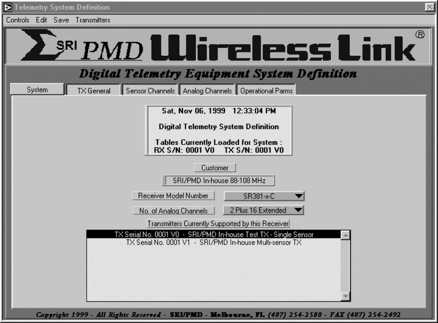
OM-06-320 REV E
- 52 - 99-500-001
FIGURE 7-1 SAMPLE CONFIGURATION DISPLAY SCREEN
7.1.1 “System” Display
A Digital Telemetry System is comprised of a single receiver along with one
(1) to 16 transmitters for which the receiver is currently configured. The
“System” display depicts this information and includes the following detailed
information.
1) Title block – shows current date, the RX serial number for the displayed
Digital Telemetry System as well as the TX serial number currently
active for display and/or edit purposes. When the configuration display
is initially activated, the active TX serial number is always the first
TX from the list of all supported TX’s.
2) Customer - a 30 character text field which normally defines the customer
of this particular RX.
3) Receiver Model Number - depicts the model number for the displayed RX.
4) Number of Analog Channels – shows the number of analog channels for the
RX. The first 2 channels (i.e., analog channels 1 and 2) are located on
the front panel of the receiver via BNC connectors. Extended channels 1
through 16 (if present) are provided via the rear panel "Analog"
connector.
OM-06-320 REV E
- 53 - 99-500-001
5) Transmitters Currently Supported by this Receiver - a table containing
the list of transmitters which the RX is configured to support. The
table includes the TX serial number and the text description of that
serial number. The table is ordered by transmitter index that also
corresponds to the rear panel dipswitch selection for activating TX’s.
Reference section 3 of this manual for further description of the dip
switch settings required to activate interfacing with different
transmitters.
All remaining screens of the configuration display pertain to detailed
information about a particular transmitter. The transmitter being displayed
is indicated in both the title block of the “System” display and via a
selection indicator in the “Transmitters Currently Supported by this Receiver”
table. To select viewing of another TX, users should move the cursor to the
table entry corresponding to that TX and click the mouse on that entry. A
“Loading TX Tables” indicator will be shown after which all other display tab
selections will reflect the new TX selection.
7.1.2 “TX General” Display
General information pertaining to the specific TX selected through the
“System” display as discussed above includes the following information:
1) Serial Number – displays the serial number of the current TX. The
serial number includes the basic 4-digit serial number plus a 1-digit
version number for this particular definition.
2) Description - a 50 character description of this particular version
definition of the TX.
3) Transmitter Model Number - depicts the model number for the displayed
TX.
4) Transmit Frequency - indicates the current transmit frequency associated
with this TX.
5) Transmit Baud Rate - indicates the current transmit baud rate associated
with this TX.
6) Configured Sensor Channels - depicts the number of sensor channels which
were configured (i.e., built) for the associated TX.
7) Active Sensor Channels - shows the number of sensor channels that have
been activated for this particular version definition of the associated
TX. The number of active sensor channels must always be less than or
equal to the number of configured sensor channels.
8) Excitation Voltage - indicates the VDC level of the output excitation
voltage from the TX for sensors requiring a drive voltage.
9) Front-end Gain - depicts the fixed gain setting configured (i.e., built)
for the associated TX. The fixed gain precedes the programmable gain
stage of the TX and is established at the factory by installed hardware.
7.1.3 “Sensor Channels” Display
Transmitters may be configured for 1 to 16 “active” sensor input channels.
The “Sensor Channels” display shows the configuration of each of these inputs
as well as defining the time period over which the sensor is sampled. The
following sections describe the details of this display.
OM-06-320 REV E
- 54 - 99-500-001
7.1.3.1 Sampling Dwell Control
The dwell control (labeled as “Dwell Cont” on the display) setting determines
the sampling algorithm that will be employed for multiple sensor channel
systems. This field has no meaning for single sensor channel systems and will
typically be set to 0 for these cases. For all multi-sensor channel systems,
the dwell control works the same regardless of configured sensor type.
For multi-sensor channel, lower speed systems (i.e., 900 MHz ST-32x models),
the dwell control field reflects the number of individual measurement samples
that are taken for the channel before the multiplex logic switches to the next
channel. The actual sensor sampling rate is determined as TX Baud Rate
divided by 11.
For example, a TX configured for a 25 Kbps baud rate will result in an
aggregate sampling rate of ~2272.72 samples per second (i.e., 25K/11) or a
sampling period of 440 micro-seconds. If a system defined with four (4)
active sensor channels has the dwell control set to 1 for each, the logic will
switch channels between each sampling period, thus producing a single channel
sampling rate of ~568.18 samples per second (i.e. 2272.72/4) or a sampling
period of 1.76 milli-seconds.
If for this same definition the dwell control is taken to 2272 for each
sensor, the system will “dwell” on each input for a period of approximately
one (1) second before switching to the next channel. During the one (1)
second period, the system will transmit 2272 consecutive samples of the active
sensor channel. On the receive side, the currently selected sensor channel is
indicated via address lines output on the digital output interface.
For these lower speed systems, a requirement exists that the end of an even
16-sample period must coincide with the end of a sensor channel dwell period,
unless the sensor channel dwell period is greater than 16 samples. In the
latter case, the end of the channels dwell period must coincide with the end
of an even 16-sample period. Hence, for the four (4) sensor channel system
discussed above, dwell selections of 4, 8, 2, 2 are valid (i.e., total of 16
samples) as is 32, 8, 7, 1. A setting of 64, 64, 64, 1 would be invalid.
For higher speed systems (i.e., 88-108 MHz ST-36x models), a minimum dwell
period of 32 samples exists for each channel. As such, the dwell control
field reflects the number of 32 sample periods that are taken for the channel
before the multiplex logic switches to the next channel. For these systems,
the actual minimum sampling rate is determined as TX Baud Rate divided by 9.
For example, a TX configured for a 250 Kbps baud rate will result in an
aggregate sampling rate of ~27777.77 samples per second (i.e., 250K/9) or a
sampling period of 36 micro-seconds. If a system defined with four (4) active
sensor channels has the dwell control set to 1 for each, the logic will switch
channels between each set of 32 sample periods. This will produce a single
channel dwell rate of 1.152 milli-seconds (i.e. 32 x 36 micro-seconds).
During this dwell period, the TX and hence RX will output 32 consecutive
samples of the sensor.
7.1.3.2 Sensor Definitions
The remaining fields on the “Sensor Channels” display define the configuration
of the sensor channel itself. This includes the following fields:
OM-06-320 REV E
- 55 - 99-500-001
1) Sensor Type Assignment – displays the type of sensor which will be
connected to the sensor input channel (i.e., strain gage, pressure
transducer, ...).
2) Sensor Scale/Sensor Offset – fields which further define the
characteristics of the exact sensor being utilized. The interpretation of
these fields varies with each type of defined sensor.
3) Measurement Units – defines the measurement units which should be utilized
for the sensor. This field also varies with the sensor type and includes
selection such as milli-volts DC (mVDC), micro-strain (uE), degree’s C/F,
and so forth.
4) Minimum/Maximum – controls the range of measurement units which the sensor
channel is configured to measure.
The definition and content of each of these fields varies based on the
configured sensor type as defined in the following paragraphs.
7.1.3.2.1 Generic Analog Voltages
There are two (2) possible selections under the “Sensor Type Assignment”
utilized to define sensors in terms of generic analog voltages. These are
“Generic 0-5 VDC” and “Generic Analog Voltage”.
The “Generic 0-5 VDC” selection is unique from all other sensor types in that
it is limited to a single ended input voltage. As such, the Signal+ input for
the channel contains a voltage between 0 and 5 VDC referenced to the ground
source of the TX power supply. Signal– is not utilized for this case.
The “Measurement Units” for a “Generic 0-5 VDC” channel is limited to mVDC and
the minimum and maximum range values can be set anywhere from 0 to 5000 mVDC.
Note that for this sensor type, the transmitter does not apply any gain.
Setting the minimum and maximum range values to other than 0 and 5000 simply
causes the RX gain setting to be increased. Sensor Scale/Sensor Offset fields
have no meaning for this sensor type.
The “Generic Analog Voltage” selection measures a differential voltage range
between the Signal+ and Signal– inputs. The measurement units may be
specified as mVDC or micro-volts DC (uVDC). The minimum and maximum range
values can be set anywhere from -1250 to +1250 for mVDC and –32768 to +32768
for uVDC although this may be further limited by the minimum gain settings of
the TX. Scale/Sensor Offset have no meaning for this sensor type.
7.1.3.2.2 Strain Gages
There are three (3) possible selections under the “Sensor Type Assignment”
utilized to define strain gage sensor types. These are “Strain Gage – 1
Active Arm”, “Strain Gage – 2 Active Arms”, and “Strain Gage – 4 Active Arms”.
The proper selection is determined by the balanced bridge configuration
utilized for the implementation of the strain gage. Reference appendix B of
this document for further information on balanced bridge configurations.
Regardless of the number of active arms, the “Sensor Scale” field for a strain
gage defines what is known as the gage factor. Most strain gages incorporate
a gage factor of 2.0, although custom sensors may vary from this setting. The
range of gage factors supported by this field is 0.0 to 255.996 in
approximately 0.004 count increments. The Sensor Offset field has no meaning
for this sensor type.
OM-06-320 REV E
- 56 - 99-500-001
The measurement units for a strain gage is limited to micro-strain (uE). The
minimum and maximum range values can be set anywhere from -32768 to +32768,
although this may be further limited by the minimum and maximum gain settings
of the TX.
7.1.3.2.3 Thermocouple’s
There are two (2) possible selections under the “Sensor Type Assignment”
utilized to define thermocouple sensor types. These are “Type J
Thermocouple”, and “Type K Thermocouple”. The Sensor Scale/Sensor Offset
fields have no meaning for these sensor types.
The measurement units for a thermocouple may be selected between “Degree’s C
(°C)” and “Degree’s F (°F)” corresponding to Celsius and Fahrenheit
respectively. The minimum and maximum range values can be set anywhere from -
32768 to +32768, although this may be further limited by the minimum and
maximum gain settings of the TX as well as limitations of the specified
thermocouple type.
7.1.3.2.4 Pressure Transducers
The “Sensor Type Assignment” can also be selected to “Pressure Transducer”.
The measurement units for a pressure transducer may be selected between Pounds
per Square Inch (PSI) or Killi-grams per Square Centi-meter (kg/cm^2). The
minimum and maximum range values can be set anywhere from -32768 to +32768,
although this may be further limited by the minimum and maximum gain settings
of the TX as well as limitations of the specified transducer type.
The “Sensor Scale” field for a pressure transducer defines the output voltage
range of the sensor in terms of mVDC/(1000 PSI) or mVDC/(1000 kg/cm^2)
depending upon the selected measurement units. For example, a pressure
transducer which outputs a 10 mVDC level for 500 PSI would have a “Sensor
Scale” field of 20.0.
The range of “Sensor Scale” factors supported by this field is 0.0 to 255.996
in approximately 0.004 count increments. The Sensor Offset field has no
meaning for this sensor type.
7.1.3.2.5 Accelerometers
The “Sensor Type Assignment” can be selected to “Accelerometer”. The
measurement units for an accelerometer are limited to Gravitational Forces
(G’s). The minimum and maximum range values can be set anywhere from -32768 to
+32768, although this may be further limited by the minimum and maximum gain
settings of the TX as well as limitations of the specified accelerometer type.
The “Sensor Scale” field for an accelerometer defines the output voltage range
of the sensor in terms of mVDC/G. For example, an accelerometer which outputs
a 25 mVDC level for 5 G’s would have a “Sensor Scale” field of 5.0.
The range of “Sensor Scale” factors supported by this field is 0.0 to 255.996
in approximately 0.004 count increments. The Sensor Offset field has no
meaning for this sensor type.
OM-06-320 REV E
- 57 - 99-500-001
7.1.3.2.6 Thermistors
The “Sensor Type Assignment” can be selected to “Thermistor”. The measurement
units for a thermistor may be selected between “Degree’s C (°C)” and “Degree’s
F (°F)” corresponding to Celsius and Fahrenheit respectively. The minimum and
maximum range values can be set anywhere from -32768 to +32768, although this
may be further limited by the minimum and maximum gain settings of the TX as
well as limitations of the thermistor circuit implementation.
Thermistors are typically incorporated into a balanced bridge configuration or
a simpler voltage divider circuit. Reference appendix B of this document for
further information on thermistor sensor implementations.
The “Sensor Scale” field for a thermistor defines the output voltage range of
the sensor in terms of mVDC/(°C) or mVDC/(°F) based on which measurement units
have been selected for the channel. The range of “Sensor Scale” supported by
this field is 0.0 to 255.996 in approximately 0.004 count increments.
The “Sensor Offset” field defines the °C or °F which are represented by a 0
differential input voltage been the Signal+ and Signal– inputs to the TX. The
range of the “Sensor Offset” field for a thermistor is –32768 to +32768.
For example, a thermistor circuit which produces a +10 mVDC output for 100 °C
input and a 0 mVDC output for a 50 °C input would have a “Sensor Offset” value
of 50 and a “Sensor Scale” field of 5.0.
7.1.4 “Analog Channels” Display
Receivers may be configured for 1 to 18 analog output channels. Channels 1
and 2 are known as the “Basic Channels” and are located on the front panel of
the RX via BNC connectors. Channels 3 through 18 are optional and designated
as “Extended Channels” located on the rear panel “Analog” connector.
The “Analog Channels” display depicts each of the configured analog channels
in tabular format. Each entry provides the following information for the
channel:
1) TX Channel Assignment – displays the TX sensor channel that has been
assigned to this RX analog output channel. Note that any given TX sensor
channel may only be assigned to one (1) analog output channel.
2) Data Filtering – specifies the type of data filtering which is being
performed on the samples prior to output to the analog channel. Supported
data filtering options is discussed in more detail in section 2 of this
document.
3) Output Voltage Range – this field is only present on the “Extended
Channels” and specifies the output VDC levels that should correspond to the
minimum and maximum measurement unit values for the sensor. Valid settings
include 0 to +5 VDC, 0 to +10 VDC, -5 to +5 VDC, and –10 to +10 VDC. Note
that “Basic Channels” are limited to 0 to +5 VDC output voltage ranges.
In addition to sensor channels, an analog output may also be assigned to the
detected transmitter operational temperature. This detected temperature is
what is utilized by the receive system to perform temperature based gain and
offset adjustment functions. When presented on an analog output, 0 °C
OM-06-320 REV E
- 58 - 99-500-001
corresponds to the minimum output voltage while +128 °C corresponds to the
maximum output voltage.
7.1.5 “Operational Parameters” Display
The “Operational Parameters” of the Digital Telemetry System control the
operational characteristics of the system with respect to link acquisition,
signal tracking, and so forth. The factory settings of these fields have been
established through extensive testing by SRI/PMD and are, in general,
applicable to the vast majority of system applications. Periodically a unique
customer environment or requirement lends itself to minor modifications to
these programmable parameters.
7.1.5.1 Transmitter Parameters
For all Digital Telemetry Systems, there are two (2) parameters applicable to
transmitter operation. These are:
1) Target Transmit Gain % - establishes what amount of the total required
system gain for sensor channels should be achieved through the transmitter
as opposed to the receiver. This parameter is typically set to 90%, thus
allowing for offset and gain errors within the sensor interface without
causing the sensor input to exceed the measurement range of the
transmitters digitizer. Lowering this parameter increases the amount of
external offset/gain errors that can be tolerated at the price of reducing
the total measurement resolution through the system.
2) Frame Sync Value – establishes the data content of the 8-bit frame sync
transmitted across the wireless link. The frame sync data allows the
receive side to detect and maintain correct data synchronization with the
incoming bit stream from the transmitter.
For 88-108 MHz Digital Telemetry Systems, operational parameter tables are
also present for “TX Frequency Cal” and “TX Frequency Deviation Cal”. These
tables establish the correct settings within the transmitter to achieve a
selected output transmit frequency with a known frequency deviation amount.
7.1.5.2 Receiver Parameters
For all Digital Telemetry Systems, there is a single common parameter
applicable to receiver operation. This is:
1) In-sync Error Threshold - indicates the number of consecutive frames which
the receiver will tolerate being in error before declaring a loss of
synchronization and forcing the system back into signal acquisition mode.
Increasing this value allows the system to tolerate longer periods of
signal drop out at the cost of not detecting data sync slips as quickly.
For 88-108 MHz Digital Telemetry Systems, an operational parameter table is
also present for “RX Frequency Cal”. This table establishes the correct
settings within the receiver to achieve a selected input tuning.
All remaining receive side operational parameters are dependent upon the mode
of operation of the wireless link. Lower speed systems (i.e., 900 MHz ST-32x
OM-06-320 REV E
- 59 - 99-500-001
models) operate in what is known as an asynchronous receive mode while higher
speed systems (i.e., 88-108 MHz ST-36x models) operate in synchronous receive
mode. The following paragraphs detail the parameters associated with each
mode of operation.
7.1.5.2.1 Asynchronous Operation
Asynchronous receive mode operational parameters include the following:
1) USART Retry Count - indicates the number of times the receive logic
attempts to achieve USART data frame synchronization (i.e., proper
start/stop bits) before completely restarting the acquisition process.
2) USART In-sync Threshold - controls the number of times the receive logic
must detect proper USART data byte synchronization (i.e., correct
start/stop bits) before proceeding on to attempt to find data frame
synchronization. Increasing this number makes it more difficult for the
system to falsely declare USART synchronization at the expense of increased
acquisition time.
3) Frame Sync Search Count - establishes the number of bytes the receive logic
will scan looking for frame sync on the background data channel after USART
synchronization has been declared. Since the frame sync is transmitted
once per data frame, this value should at least be a frames worth of bytes
(i.e., 32) or greater.
7.1.5.2.2 Synchronous Operation
Synchronous receive mode operational parameters include the following:
1) Frequency Range Control, Positive Frequency Range Control, and Frequency
Step Size Control - establishes the search frequency range utilized by the
receiver during acquisition. While attempting to locate a signal, the
receiver scans the possible valid frequency range looking for a signal from
the Digital Telemetry Transmitter. This is done by continuously stepping
the receive frequency over a range of settings. These values establish the
size of each step where each unit count equals approximately 20 KHz.
Hence, the setting of the step size x 20 KHz x Frequency Range Control
equals the approximate scan width of the receive acquisition logic. The
(step size x 20 KHz x Positive Frequency Range Control) + Transmit
Frequency equals the starting point of the scan, which then proceeds in a
negative direction.
2) Bit-sync Range Control and Bit-sync Step Size Control - establishes the
search bit-sync range utilized by the receiver during acquisition. While
attempting to locate a signal, the receiver scans the possible valid
frequencies and at each frequency setting attempts to lock up the bit-sync.
This is done by continuously stepping the bit-sync over a range of
settings. The step size control set the size of each step where each unit
count equals approximately 250 bps. Hence, the setting of step size x 200
bps x Bit-Sync Range Control equals the approximate bit rate scan width of
the receive acquisition logic.
3) Signal Detect Threshold – establishes the minimum signal level that must be
detected for the system to attempt data lock on a signal. Lowering this
value increases the potential sensitivity of the system for locking onto
weak signals at the cost of increasing acquisition time for all signals.
4) Frame-sync Bit Search Count and Frame-sync Byte Search Count – The bit
search count establishes the number of bits the receive logic will scan
OM-06-320 REV E
- 60 - 99-500-001
looking for the correct orientation of the background data channel with
respect to the primary data channel. Since the word length of the system
is 9 bits, this is the minimum value this field should be set to.
Increasing it beyond this setting allows some noise hits to be tolerated
during the data sync lock attempt logic at the price of increasing
acquisition time. The byte search count control the number of bytes the
receiver attempts to gain frame lock with the incoming signal. This field
controls how many background channel byte locations are scanned looking for
the frame sync value. Since the frame length of the system is 32 words,
this is the minimum value this field should be set to. Increasing it
beyond this setting allows some noise hits to be tolerated during the data
sync lock attempt logic at the price of increasing acquisition time.
5) AFC Minimum Offset Threshold and AFC Loop Multiplier Control – once the
system is in-sync and tracking a signal, the Automatic Frequency Control
(AFC) logic tracks dynamic changes in the transmit frequency due to doppler
or changing TX operational temperatures. The minimum offset threshold
establishes how large of a frequency error must be present before AFC
tracking takes action while the loop multiplier control establishes how
fast the logic tracks a frequency error.
6) Bit-sync Tracking Lead Multiplier and Bit-sync Tracking Lag Multiplier –
once the system is in-sync and tracking a signal, the bit-sync tracking
logic tracks dynamic changes in the transmit baud rate due to doppler or
changing TX operational temperatures. The lead and lag multiplier values
establish the constants utilized in a classic type 2 loop filter for this
tracking function.
7.2 Changing System Definitions
Extended software users have available menu selections from the main Digital
Control Software display for “Table Control : Edit Existing Telemetry System
Definition : Edit Current Serial Port System” to change the definition of the
system currently connected to the PC’s serial port.
Alternatively, selecting “Table Control : Edit Existing Telemetry System
Definition: Edit a Defined Telemetry System” can be utilized to edit a system
defined on the PC’s disk. Users who modify the definition of a disk resident
system should insure that the disk file used properly reflects all
configuration and calibration data that may have been modified in the EEProm
memory space of the system in question. After editing, the new definition
files should be downloaded to the receiver and/or transmitter to affect the
update.
Either of these selections produces the same display as the configuration
screens discussed above but enable editing of most configurable parameters.
7.2.1 Transmitter Definition Control
To change parameters of an existing transmitter serial number and version, the
user need only select the appropriate definition from the “Transmitters
Currently Supported by this Receiver” on the “System” configuration page and
then proceed to the appropriate tab selections for the parameter of interest
and make the necessary changes.
Users wishing to maintain the current definition but wanting to create a new
version of a transmitter configuration for an alternate application should
OM-06-320 REV E
- 61 - 99-500-001
select “Transmitters : Define/Add New Transmitter”. If the user currently has
only a single version of the transmitter definition existing, the system will
automatically create an identical definition to that version and assign it to
a new serial number with the version digit portion incremented by 1. For
example, TX S/N 1234 V0 would produce the new version of TX S/N 1234 V1.
If the user already has multiple versions of the transmitter definition
existing or owns multiple Series 300 TX’s, the system will query the user as
to which of the transmitter definitions the new one should be based on. It
will then create an identical definition and assign the next available version
digit number for that serial number.
For users owning multiple Series 300 systems, transmitter definitions
supported by one (1) receiver may be added to another receiver by selecting
“Transmitters : Add Existing Transmitter”. The user will then be queried as
to which transmitter to add.
Regardless, any of the above actions will cause the new transmitter serial
number to appear on the “Transmitters Currently Supported by this Receiver”
list. The user may then select that definition and edit it accordingly.
In the case where a user no longer requires a specific transmitter definition,
selecting “Transmitters : Remove/Delete a Currently Supported Transmitter”
should be used to delete the definition. After querying the operator as to
which definition should be deleted, that specific serial number will be
removed from the “Transmitters Currently Supported by this Receiver” list.
Furthermore, the operator will be queried as to whether the delete process
should also remove disk files associated with that definition. Answering yes
will totally eliminate the transmitter definition from both the EEProm memory
space and the disk resident versions.
7.2.2 Editing Parameters
In general, users of the extended software capabilities may modify any
parameter identified in section 7.1 of this document with the exception of
those associated with the actual hardware build of the system. Consistent
with this, the user is not allowed to modify the following parameters even
with the extended software capabilities:
1) Receiver Model Number
2) Number of Analog Channels
3) Transmitter Serial Number – the user may create a new version of an
existing 4 digit basic serial number, but is not allowed to change the
basic serial number value.
4) Transmitter Model Number
5) Configured Sensor Channels – the user may modify the Active Sensor Channels
to be anything less than or equal to the configured, but may not change the
configured sensor channels.
6) Front-end Gain
Changes to editable parameters are via standard Windows techniques with menu
type selection options, up/down control arrows, or standard text entry
methods. For text entry fields, the system supports standard copy/paste
functions under an “Edit” menu.
OM-06-320 REV E
- 62 - 99-500-001
Some fields within the configuration are interrelated. Where possible, the
Digital Control Software will attempt to insure that the user cannot create
invalid relationships during the edit process. For example, since any given
sensor input channel can only be assigned to a single analog output channel,
changing a sensor channel output assignment will cause the system to
automatically reassign the previous analog channel which might have been
assigned to that sensor.
In some cases the automatic correction logic is not practical. For instance,
a change to a sensor type assignment requires that all parameters associated
with the sensor type be established before the logic can validate the
settings. For these instances, the logic waits until the user invokes a save
operation before testing the validity of the new configuration. If an invalid
condition is determined to exist, the save function is inhibited until the
configuration is corrected to a valid state.
For instance, a system built to a front-end gain setting of x25 has a minimum
total TX gain of x50 (ignoring the unity gain setting for a Generic 0 to 5 VDC
sensor type selection). Defining a “Generic Analog Value” sensor with a
measurement range of +/- 200 mVDC would create a condition where the maximum
sensor inputs would exceed the TX’s digitizer input range (i.e., 200 x 50 =
10,000 mVDC > +/- 2.5 VDC). If a save operation is invoked with these
settings, the Digital Control Software will detect the violation, notify the
operator, and inhibit the save function from proceeding.
7.2.3 Saving Updates
When an extended software user has enabled editing of a telemetry system
definition, the “Save” menu provides four (4) options for saving changes.
These are:
1) Select “Save : Save to Disk” to update the disk resident copy of the
telemetry system definition without changing a receivers EEProm version.
2) Select “Save : Save to Disk and Exit” to update the disk resident copy of
the telemetry system definition and exit the edit session.
3) Select “Save : Save to Disk and Download to Serial Port System” to update
the disk resident copy of the telemetry system definition as well as the
receivers EEProm version currently connected to the PC’s serial port.
4) Select “Save : Save to Disk, Download to Serial Port System and Exit” to
update the disk resident copy of the telemetry system definition as well as
the receivers EEProm version currently connected to the PC’s serial port
and exit the edit session.
In general, users are encouraged to update both the disk resident and EEProm
versions of the definitions to insure consistency. For edit sessions
involving extensive changes, periodic “Save : Save to Disk” selections can be
utilized to backup the change process at interim time periods.
For system definitions involving multiple transmitters or versions of the same
transmitter, the Digital Control Software is limited to maintaining a single
TX definition within memory at any given time. When an editing session
involves changes to multiple TX definitions, the user should select “Save :
Save to Disk” upon completing the changes to one (1) TX definition before
proceeding to the next definition. After all changes have been accomplished,
OM-06-320 REV E
- 63 - 99-500-001
the operator may select “Save : Save to Disk and Download to Serial Port
System” one time to update the EEProm resident version.
When updating a serial port system, the Digital Control Software will
automatically detect if a Digital Telemetry Transmitter is connected to the
programming interface of the receiver. If so, the user will be queried as to
whether the transmitter should also be updated with its definition. Selecting
yes will cause the system to prompt the operator for which definition should
be loaded into the programming interface transmitter.
To insure proper operation of the Digital Telemetry System, the transmitter
definition must be updated via the programming interface for any changes
affecting sensor definitions, dwell period controls, and/or transmit
frequency/baud rate. If the user does not have the transmitter connected to
the programming interface upon exiting the edit session, it may be updated at
a later time via the “Table Control : Download : Transmitter via Programming
Interface” from the Digital Control Software main screen.
7.3 Printing System Reports
From the main screen of the Digital Control Software, the user may select
“Table Control : Print Telemetry System Report : Print Current Serial Port
System” to generate a text report to a printer detailing the configuration of
the telemetry system currently connected to the PC’s serial port. The report
includes all information about the systems configuration discussed in previous
paragraphs of this section.
Alternatively, selecting “Table Control : Print Telemetry System Report :
Print a Defined Telemetry System” allows the user to print a configuration
report on any system defined on the PC’s disk.
As previously mentioned, the system maintains records on all calibration
sessions for a telemetry system. When printing a report, if the system
detects the presence of these records, it will query the operator as to
whether a calibration report should be printed in addition to the
configuration report. If selected, the calibration report includes detailed
information pertaining to measurements made, associated gain/offset
adjustments affected by the calibration process, and before/after gain/offset
curves of the telemetry system.
The Digital Telemetry System report requires a graphics compatible printer.
Users may establish the printer selection and other configurable printer
options by selecting “General : Printer Setup...” from the main screen.

OM-06-320 REV E
- 64 - 99-500-001
SECTION 8 MAINTENANCE
In order to ensure that the Digital Telemetry System is always ready for
operation, it should be checked periodically such that defects may be
discovered and corrected before they develop into any serious damage or system
failure. A minimal preventive maintenance program will significantly increase
the systems life span.
This section describes the necessary preventive maintenance checks and tests
the user can perform to easily identify most defects and problems. Any other
defects or problems discovered during the normal operation of the system
should be noted for future corrective measures.
CAUTION
Stop the operation of the system
immediately if a problem is noted during
normal operation that can otherwise damage
the system.
This section also describes the corrective maintenance checks that can be
performed on the Digital Telemetry Systems.
8.1 Maintenance Concept
The maintenance concept for the Digital Telemetry Equipment is limited to
period preventive maintenance actions as identified in the following sections.
8.2 Preventive Maintenance Requirements
The following is a recommended timetable for performing preventive maintenance
checks on Series 300 Digital Telemetry Systems.
CAUTION
Power to the chassis must be turned OFF
when performing preventive maintenance on
the equipment.
8.2.1 Inspection
The Digital Telemetry System, chassis, and interface cables should be
inspected periodically for defects or physical damage developed during
operation. Inspect all the interface cables for cracks, breaks and proper
seating with their mating connectors. Inspect all cables for frayed, broken
or damaged wires. In addition, inspect all connections for accumulation of
dirt, grease, or any foreign material that can cause a non-connection. If a
cable is found damaged or non-repairable, it should be replaced before
operating the system again.
OM-06-320 REV E
- 65 - 99-500-001
Inspection should be performed at least once every month. The frequency of
inspection should be increased for units exposed to dusty or heavy particulate
environments.
8.2.2 Cleaning
Clean the outside surfaces and areas around the connectors periodically.
Clean the surfaces with a clean, soft, lint-free cloth. Clean the areas
around the connectors with a soft bristle brush. Cleaning can be done with a
cloth moistened in warm soapy water after all the excess water has been
squeezed out of the cloth.
To remove grease, fungus, or corrosion, use a cloth dampened in high quality
electronic cleansing solution.
Cleaning should be done at least once every month. The frequency of cleaning
should be increased for units exposed to dusty or heavy particulate
environments.
8.3 Corrective Maintenance Requirements
SRI/PMD does not recommend any corrective maintenance actions be performed for
fielded units except as specifically directed by SRI/PMD during any potential
service assistance calls. In general, if a transmitter or receiver is
exhibiting suspect behaviors, the operational start-up procedures discussed in
section 4 of this document should be followed in an attempt to isolate
potential areas of failure. Following this action, SRI/PMD should be
contacted directly for further maintenance recommendations.
OM-06-320 REV E
- 66 - 99-500-001
APPENDIX A MODEL DEPENDENT PIN ASSIGNMENTS
The following pages detail the pin assignments for the various models of the
Series 300 Digital Telemetry Transmitters. The indicated signal names
correspond to the definitions provided in section 3 of this document.
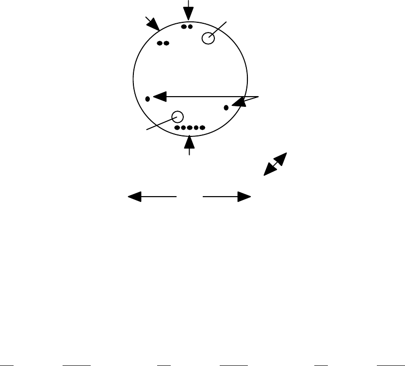
OM-06-320 REV E
- 67 - 99-500-001
A.1 Single Channel Model ST-321, ST-326, and ST-361
The models ST-321, ST-326, and ST-361 are a 1.75” diameter disk shape. For
product versions limited to one (1) sensor input channel, a single transmitter
card is housed in the 0.6” tall enclosure. The pinouts for this product
version is depicted in the following diagram.
Pin Group D
Pin Group B
15
12
1
Pin Group C
2
1.75"
0.60”
Mounting
Hole
Mounting
Hole
Pin Group A
12
Note: Mounting holes are ~0.170” in diameter.
They are centered at an offset of +/- 0.600” from the horizontal center line
and +/- 0.175 from the vertical center line.
FIGURE A-1 MODEL ST-321/326/361 SINGLE SENSOR TX PIN LOCATIONS
The pin assignments reflected in the following table apply to this packaging
style.
TABLE A-1 MODEL ST-321/ST-326/ST-361 SINGLE CHANNEL TX PIN ASSIGNMENTS
PIN SIGNAL PIN SIGNAL PIN SIGNAL
A1 VCC (+7 to 18 VDC) B1 PROG_VCC (+5 VDC) C1 SIG-1
A2 GROUND B2 PROG_RESET* C2 SIG+1
B3 PROG_CLK
B4 PROG_DAT D1 EXCOM-
B5 PROG_GND D2 EXCOM+
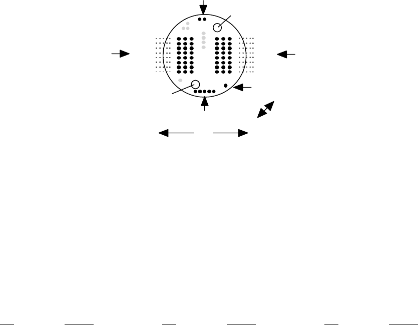
OM-06-320 REV E
- 68 - 99-500-001
A.2 Multi-Channel Model ST-321, ST-326 or ST-361
The models ST-321, ST-326 and ST-361 are a 1.75” diameter disk shape. For
product versions from two (2) to 16 sensor inputs, a dual card arrangement is
housed in the 0.85” tall enclosure. The pinouts for these product versions is
depicted in the following diagram.
Pin Group B
Pin Group D
1
816 24
17
91
824
17
16
9
Mounting
Hole
Mounting
Hole
1
Pin Group F Pin Group E
Pin Group A
12
15
Sensor 1
Sensor 3
Sensor 5
Sensor 7
Sensor 9
Sensor 11
Sensor 13
Sensor 15
Sensor 16
Sensor 14
Sensor 12
Sensor 10
Sensor 8
Sensor 6
Sensor 4
Sensor 2
1.75"
0.85”
Note: Mounting holes are ~0.170” in diameter.
They are centered at an offset of +/- 0.600” from the horizontal center line
and +/- 0.175 from the vertical center line.
FIGURE A-2 MODEL ST-321/326/361 MULTI-SENSOR TX PIN LOCATIONS
Pin locations shown in gray in this figure indicate factory test points which
may be present on the transmitter but which should not be utilized for end-
user applications.
The pin assignments reflected in the following table apply to this packaging
style.
TABLE A-2 MODEL ST-321/ST-326/ST-361 MULTI-CHANNEL TX PIN ASSIGNMENTS
PIN SIGNAL PIN SIGNAL PIN SIGNAL
A1 VCC (+7 to 18 VDC) B1 PROG_VCC (+5 VDC) D1 EXCOM+
A2 GROUND B2 PROG_RESET*
B3 PROG_CLK
B4 PROG_DAT
B5 PROG_GND
E1 SIG+01 E17 EXC-01 F9 SIG-16
E2 SIG+03 E18 EXC-03 F10 SIG-14
E3 SIG+05 E19 EXC-05 F11 SIG-12
E4 SIG+07 E20 EXC-07 F12 SIG-10
E5 SIG+09 E21 EXC-09 F13 SIG-08
E6 SIG+11 E22 EXC-11 F14 SIG-06
E7 SIG+13 E23 EXC-13 F15 SIG-04
E8 SIG+15 E24 EXC-15 F16 SIG-02
E9 SIG-01 F1 SIG+16 F17 EXC-16
E10 SIG-03 F2 SIG+14 F18 EXC-14
E11 SIG-05 F3 SIG+12 F19 EXC-12
E12 SIG-07 F4 SIG+10 F20 EXC-10
E13 SIG-09 F5 SIG+08 F21 EXC-08
E14 SIG-11 F6 SIG+06 F22 EXC-06
E15 SIG-13 F7 SIG+04 F23 EXC-04
E16 SIG-15 F8 SIG+02 F24 EXC-02
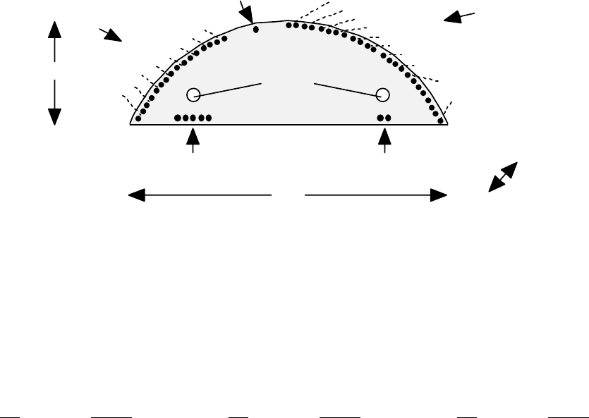
OM-06-320 REV E
- 69 - 99-500-001
A.3 Piston Mount Multi-Channel Model ST-363
The model ST-363 is a moon shaped version of the telemetry system typically
utilized for piston mount or similar types of applications. For product
versions up to 16 sensor inputs, a dual card arrangement is housed in the
0.65” tall enclosure. The pinouts for these product versions is depicted in
the following diagram.
1.17"
3.64" 0.65”
Pin Group B
51 21
Pin Group A
Mounting
Holes
1
24
1
16
1
Pin Group D
Pin Group C
Pin Group E
EXCITATION -
VOLTAGES
SENSOR 1
SENSOR 3
SENSOR 5
SENSOR 7
SENSOR 9
SENSOR 11
SENSOR 13
SENSOR 15
SENSOR 2
SENSOR 4
SENSOR 6
SENSOR 8
SENSOR 10
SENSOR 12
SENSOR 14
SENSOR 16
Note: Mounting holes are ~0.170” in diameter. They are centered at an
offset of +/- 1.150” from the vertical center line and at +0.450 from the flat
side edge. The mold shape is compatible with a 4.00” piston.
FIGURE A-3 MODEL ST-363 MULTI-SENSOR TRANSMITTER PIN LOCATIONS
The pin assignments reflected in the following table apply to this packaging
style.
TABLE A-3 MODEL ST-363 TRANSMITTER PIN ASSIGNMENTS
PIN SIGNAL PIN SIGNAL PIN SIGNAL
A1 VCC (+7 to 18 VDC) B1 PROG_VCC (+5 VDC) C1 EXCOM+
A2 GROUND B2 PROG_RESET*
B3 PROG_CLK
B4 PROG_DAT
B5 PROG_GND
D1 EXC-01 D15 SIG+07 E5 SIG+06
D2 EXC-02 D16 SIG-07 E6 SIG-06
D3 EXC-03 D17 SIG+09 E7 SIG+08
D4 EXC-04 D18 SIG-09 E8 SIG-08
D5 EXC-05 D19 SIG+11 E9 SIG+10
D6 EXC-06 D20 SIG-11 E10 SIG-10
D7 EXC-07 D21 SIG+13 E11 SIG+12
D8 EXC-08 D22 SIG-13 E12 SIG-12
D9 SIG+01 D23 SIG+15 E13 SIG+14
D10 SIG-01 D24 SIG-15 E14 SIG-14
D11 SIG+03 E1 SIG+02 E15 SIG+16
D12 SIG-03 E2 SIG-02 E16 SIG-16
D13 SIG+05 E3 SIG+04
D14 SIG-05 E4 SIG-04
Note that excitation voltages are only supported for sensor channels 1 through
8 on this model of the Digital Telemetry Transmitter.
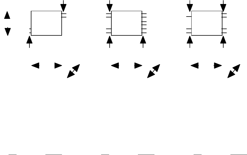
OM-06-320 REV E
- 70 - 99-500-001
A.4 Miniaturized Single Channel Model ST-364
The model ST-364 is a miniaturized, 3 component, modularized package for fixed
sensor types where mounting space and/or weight is at a premium. The actual
telemetry system is broken into a processor module and a transmitter module.
A battery pack in a similar mold form/fit is also available for this product
type. The pinouts for this product version is depicted in the following
diagram.
0.75"
0.45”
Pin Group A
Pin Group B
Pin Group C
Pin Group D
Pin Group E Pin Group F
Pin Group G
Pin Group H
Pin Group I
1
1
1
1
2
22
21
6
1
1
21
1
2
2
0.75" 0.75"
0.60"
0.38” 0.38”
Battery Processor Transmitter
FIGURE A-4 MODEL ST-364 SINGLE SENSOR TRANSMITTER PIN LOCATIONS
The pin assignments reflected in the following table apply to this packaging
style.
TABLE A-4 MODEL ST-364 TRANSMITTER PIN ASSIGNMENTS
PIN SIGNAL PIN SIGNAL PIN SIGNAL
A1 BATTENA+ D1 EX2.5V+ F1 VCC (+5 VDC)
A2 BATTENA- D2 EXCOM- F2 GROUND
B1 GROUND E1 TXDATA G1 TXDATA
B2 VCC (+5 VDC) E2 EX5.0V+
E3 GAINSEL+ H1 FREQSEL+
C1 VCC (+5 VDC) E4 GAINSEL- H2 FREQSEL-
C2 GROUND E5 SIG+1
E6 SIG-1 I1 RFOUT-
I2 RFOUT+
For this product version, some signals are not part of the standard set
described in section 3 of this document. These signals, and other
interconnect considerations for the ST-364 are as follows:
1. BATTENA+ and BATTENA- are utilized to enable the Battery Module +5 VDC output (VCC). These
pins should be open when the battery pack is not being utilized or shorted together for
active operation. Note – Pin Group A are the shorter pins when compared to Pin Group B on
the Battery Module.
2. The VCC pins on each of the three (3) modules should be interconnected. Similarly, the
GRUOND pins should also be interconnected.
3. EX2.5V+ is a 2.5 VDC excitation + signal which may be utilized for sensors just as EXCOM+ is
utilized for other transmitter models. Optionally, EX5.0V+ is a 5.0 VDC excitation + signal.
Although either can be utilized, the delivered system is configured for only one of the
OM-06-320 REV E
- 71 - 99-500-001
excitation voltage levels. Refer to the configuration data delivered with the system to
determine which pin to utilize.
4. TXDATA on the Processor Module should be interconnected to TXDATA on the Transmitter Module.
5. GAINSEL+ and GAINSEL- are an interconnect utilized to establish the sensor gain of the
system. The appropriate resistor will be factory installed by SRI/PMD. Consult the factory
for potential modifications to this resistor.
6. FREQSEL+ and FREQSEL- are an interconnect utilized to establish the transmit frequency of the
Transmitter Module. The system will be delivered with a resistor installed by SRI/PMD for
mid frequency range transmission. Test data supplied with the system will indicate
appropriate values to select alternate transmission frequencies.
7. RFOUT+ and RFOUT- are the RF output pins from the Transmitter Module. An optional external
antenna may be connected to these pins if required. RFOUT+ is the actual RF output signal
from the transmitter. RFOUT- is an internal RF GROUND signal through the Transmitter Module,
although it is NOT the system GROUND referenced above.
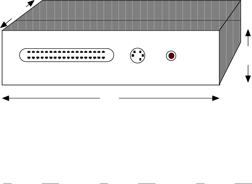
OM-06-320 REV E
- 72 - 99-500-001
A.5 Single/Multi-Channel Model ST-325 and ST-365
The model ST-366 is a less ruggedized version of the telemetry system
typically utilized for industrial or other benign type of applications. It is
housed in a plastic case with rear panel connectors and a single front panel
power LED. The pinouts for these product versions is depicted in the
following diagram.
SENSOR
18 1
36 19
PROGRAM VDC
5.5”
1.3”
3.8”
FIGURE A-5 MODEL ST-325/365 TRANSMITTER PIN LOCATIONS
The “SENSOR” connector is a 36 pin comb style connector (AMP part number
552742-1) which requires the user to provide a compatible male connector (for
example, SPC Technology Type 57-30360). The pin assignments reflected in the
following table apply to this packaging style.
TABLE A-5 MODEL ST-325/365 TRANSMITTER PIN ASSIGNMENTS
PIN SIGNAL PIN SIGNAL PIN SIGNAL
VDC Inner VCC (+7 to 18 VDC) PROGRAM1 PROG_DAT PROGRAM3 PROG_CLK
VDC Outer GROUND PROGRAM2 PROG_GND PROGRAM4 PROG_VCC
PROGRAM5 PROG_RESET*
SENSOR1 EXC-01 SENSOR13 SIG+05 SENSOR25 GND
SENSOR2 EXC-02 SENSOR14 SIG+06 SENSOR26 GND
SENSOR3 EXC-03 SENSOR15 SIG+07 SENSOR27 SIG-01
SENSOR4 EXC-04 SENSOR16 SIG+08 SENSOR28 SIG-02
SENSOR5 EXC-05 SENSOR17 EXC+COM SENSOR29 SIG-03
SENSOR6 EXC-06 SENSOR18 EXC+COM SENSOR30 SIG-04
SENSOR7 EXC-07 SENSOR19 GND SENSOR31 SIG-05
SENSOR8 EXC-08 SENSOR20 GND SENSOR32 SIG-06
SENSOR9 SIG+01 SENSOR21 GND SENSOR33 SIG-07
SENSOR10 SIG+02 SENSOR22 GND SENSOR34 SIG-08
SENSOR11 SIG+03 SENSOR23 GND SENSOR35 EXC+COM
SENSOR12 SIG+04 SENSOR24 GND SENSOR36 EXC+COM
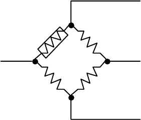
OM-06-320 REV E
- 73 - 99-500-001
APPENDIX B TYPICAL SENSOR INTERCONNECTS
The Series 300 Digital Telemetry Systems are not usually provided with the
actual sensors that they will telemeter. Most often, the end user of the
product selects and installs the appropriate sensor and provides the
interconnection to the Digital Telemetry Transmitter. This is typically
accomplished either via direct solder connections or connectorized/header
interfaces to the pins identified in appendix A of this document. The
following sections describe some of the typical sensors which may be utilized
with this product, and discusses the interconnect considerations for each
type.
B.1 Balanced Bridge Sensors (Strain/Pressure/...)
Balanced bridge sensors are most often accomplished with sensors forming what
is classically called the “Wheatstone Bridge Circuit”. As shown in the
following figure, the balanced bridge is created via four (4) nominally equal
resistance values, one (1) or more of which may vary with the parameter being
measured (i.e. strain, pressure, ...).
Excitation + (EXC+COM)
Signal - (SIG-x)
Excitation - (EXC-COM or EXC-xx)
Signal + (SIG+x)
R1
R4
R2
R3
FIGURE B-1 TYPICAL BALANCED BRIDGE CIRCUIT
The figure depicts what is known as a single active arm circuit. In this
case, R1 is the only arm of the balanced bridge that varies with the
measurement parameter. The R1 in this case is a single active gage, widely
available from a number of sensor manufacturers. R2 through R4 are fixed
resistance values (typically 120, 350, or 700 ohm each), most often formed via
a bridge completion circuit. Again, bridge completion circuits are available
from these same manufactures.
Under nominal (i.e., zero (0) measurement value) conditions, the circuit
creates a balanced, voltage divider network. As such, the excitation voltage
from the Digital Telemetry Transmitter (i.e., EXC+COM and EXC-COM or EXC-x for
multi-sensor channel systems) is divided in half via the path R1 to R4. This
creates the positive sensor signal back to the transmitter (i.e., SIG+x).
Similarly, path R2 to R3 creates the negative sensor signal (i.e., SIG-x).
As the measurement parameter varies, the resistance of the active gage varies,
thus creating a small differential voltage between Signal + and Signal -. The
magnitude of this differential voltage determines the actual measurement
value, which is then translated through by the Digital Telemetry System to the
OM-06-320 REV E
- 74 - 99-500-001
analog output port associated with that sensor. Each system is configured at
the factory for the maximum measurement range of the sensor, which determines
the maximum amount of differential voltage between the + and – Signal inputs
which will correspond to the maximum and minimum voltage outputs of the analog
port.
Users may also incorporate sensor configurations that utilize multiple active
arms. For instance, by replacing R4 with an active gage and limiting the
bridge completion circuit to R2 and R3, a two (2) active arm bridge is
created. With no changes to the telemetry system, this in affect doubles the
resolution of the circuit while halving the maximum measurement range. For
instance, a single active arm strain gage sensor may be configured to measure
+/- 1000 micro-strain (uE), which would equate to 100 uE/VDC on a +/- 10 VDC
analog output channel. By modifying the circuit to a two (2) active arm
bridge, the analog output port will reflect 50 uE/VDC if no other parameters
are modified. Similarly, a four (4) active arm system, with R1 through R4 all
being accomplished via active gages with increase the resolution by 4 when
compared to a single active arm system.
The Digital Telemetry System also supports selectable excitation voltage
levels. This feature may be utilized to reduce the current utilization of
sensors utilizing the excitation voltage. Typical sensors utilizing +5 VDC
excitation will require twice as much system current as compared to a reduced
excitation voltage of +2.5 VDC. However, the output differential voltage
associated with any given measurement value will also be reduced by half.
Although the Digital Telemetry System automatically compensates for this
reduced output value by doubling the invoked gain settings, the accuracy of
resulting measurements is reduced as a consequence. Note that the output
excitation voltage level is a configurable parameter on a per transmitter
basis. As such, this level cannot be varied for different sensor inputs to
any given, single transmitter.
It is also important to note that on multi-sensor input systems, the Digital
Telemetry Transmitter only activates the excitation voltage to any given
sensor during the actual measurement period associated with that channel.
This reduces the total power consumption of the system by eliminating current
draw from sensors that are not being actively measured. The multiplexing of
the excitation voltage is accomplished by allowing the excitation – voltage
associated with the sensor channel (i.e., EXC-x) to float during non-active
periods. In order to realize the power consumption savings of this feature,
users should not incorporate sensor configurations that tie the EXC-x signal
to an external ground reference.
B.2 Thermocouples
A thermocouple is a temperature measurement sensor that consists of two (2)
dissimilar metals joined together at one end (i.e., a junction) that produces
a small thermoelectric voltage when the junction is heated. As shown in the
following figure, this thermoelectric voltage causes a differential voltage
between the signal + and – inputs (i.e., SIG+x and SIG-x) to the Digital
Telemetry System for the particular sensor input channel.
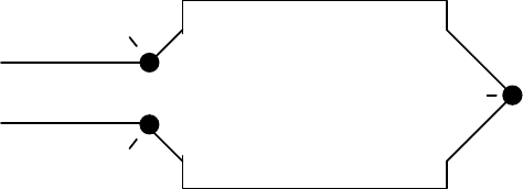
OM-06-320 REV E
- 75 - 99-500-001
JUNCTION (J1)
METAL A
(e.g., IRON)
METAL B
(e.g., CONSTANTAN)
JUNCTION (J2)
JUNCTION (J3)
SIGNAL + PIN
(SIG+x)
SIGNAL - PIN
(SIG-x)
TEMPERATURE
MEASUREMENT
POINT
FIGURE B-2 TYPICAL THERMOCOUPLE CIRCUIT
Different types of thermocouples incorporate varying types of dissimilar
metals. For instance, the Iron-Constantan version shown above is known as a
type J thermocouple, while Chromel-Alumel is utilized for type K, and so
forth. Each type of thermocouple provides varying levels of output
differential voltages for different input measurement temperatures. When
purchasing a Digital Telemetry System, the user will specify the type of
thermocouple(s) being incorporated, thus allowing the factory to establish the
appropriate gain settings for each sensor input.
Note that although the point labeled J1 in the diagram is the dissimilar metal
junction of interest, the actual pin interconnects to the Digital Telemetry
Transmitter (shown as J2 and J3 in the figure) also form dissimilar metal
junctions. If the affects of junction J2 and J3 are ignored, small offsets or
errors in the measurement value may be present, which will vary with the
transmitters operating temperature. This may be acceptable for thermocouple
applications measuring a large temperature range as compared to the variation
of operating temperature for the transmitter itself.
However, any purchased Digital Telemetry System configured for one or more
thermocouple sensor inputs will be calibrated with temperature compensation at
the factory. As described in the main text of this document, temperature
based calibration provides the means by which the systems gain and offset
values will vary with operating temperature of the transmitter. This provides
the means by which the temperature varying errors produced by junctions J2 and
J3 are eliminated, thus producing an accurate measurement representation at
the analog output port. Furthermore, end users may perform this same
calibration process in the field via the Digital Telemetry Control Software.
It should be noted that under dynamically varying transmitter operational
temperature conditions, there is sometimes a minor temperature differential
between the Signal + and – pins (i.e., J2 and J3 in the example figure) and
the detected operational temperature of the transmitter itself. This is true
since the transmitter operational temperature measurement is based on an
internal sensor embedded within the transmitter mold as opposed the Signal +
and – pins which are located on the exterior surface of the mold. In these
cases, a slight offset in sensor measurement may be present through the
telemetry system until such time as the two (2) temperatures have stabilized
and are equal.
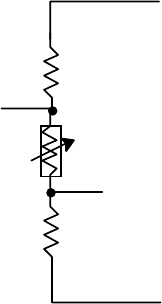
OM-06-320 REV E
- 76 - 99-500-001
B.3 Thermistors
Thermistors are sensors that vary in resistance based on temperature. This is
similar to operation of a strain gage and, in fact, thermistors may
incorporate balanced circuitry like the Wheatstone bridge to provide a
differential voltage measurement to the Digital Telemetry System proportional
to the thermistor temperature.
Thermistor circuits may also utilize a simpler voltage divider network as
depicted in the following diagram.
Excitation + (EXC+COM)
Excitation - (EXC-COM or EXC-xx)
Signal + (SIG+x)
R1
Thermistor
R2
Signal - (SIG-x)
FIGURE B-3 SIMPLE THERMISTOR CIRCUIT
This circuit is typically less accurate than the balanced bridge approach, but
may still be sufficient for some measurement applications.
The exact voltages which will be produced by a balanced bridge thermistor
configuration or the simplified voltage divider network shown above depends on
the resistance values implemented. This directly affects the necessary sensor
definition for this input in the Digital Telemetry System. Users may contact
SRI/PMD for assistance in determining these values and the corresponding
sensor definition settings for the thermistor.
B.4 Accelerometers
Accelerometers are sensors that produce a differential voltage proportional to
the acceleration forces on the sensor in a specific axis or direction. Multi-
axis accelerometers are frequently utilized (bi-axial or tri-axial) to measure
forces in more than one (1) direction. For applications incorporating multi-
axis devices, the differential voltage outputs from each axis are typically
interconnected to different sensor inputs on the Digital Telemetry System.
Most accelerometers are active devices, thus requiring an excitation voltage
in order to produce the measurement output(s). They also typically require a
significant amount of “power-on” initialization time before producing accurate
results. This initialization or settling time is usually not compatible with
the multiplexed excitation voltage of the Series 300 equipment.
To circumvent this limitation, the accelerometer power leads may be connected
to EXC+COM output (which always produces a selectable DC output voltage) and
the GROUND pin of the primary power input to the transmitter. By bypassing
OM-06-320 REV E
- 77 - 99-500-001
the multiplexed EXC-x outputs from the transmitter, power will be constantly
provided to the sensor during transmitter operation. Users need to be aware
of the extra current draw this places on the primary power source to the
transmitter and adjust the associated power budget accordingly.
B.5 Other Sensor Types
As noted within the main text of this document, the Series 300 Digital
Telemetry Systems can be configured for almost any type of sensor input,
ranging from those which produce micro-volt DC level inputs to 0 to +5 VDC
inputs. Due to the simplicity and versatility of configuring these systems,
custom sensor types can also be readily accommodated.
It is important to note that for all defined sensor types other than “Generic
0 to 5 VDC” inputs, the standard product always treats the Signal + and –
inputs (i.e., SIG+x and SIG-x) as differential, bipolar signals. As such, any
positive or negative relationship is allowed to exist between these input
signals within the configured measurement range. However, due to this
implementation, neither input should ever be tied to any ground reference of
the Digital Telemetry Transmitter via any path. Establishing a direct path
between the input sensor signals and the transmitter ground will cause offsets
that cannot be compensated for by the telemetry system.
Certain sensors require external circuitry to make them compatible with the
input/output requirements of the Series 300 equipment. For example, certain
piezoelectric type sensors require an external charge amplifier to produce a
compatible voltage output. Similarly, some sensors require an excitation
signal from a frequency source. SRI/PMD frequently delivers custom external
circuitry that can readily be connected to a standard transmitter to
accomplish these adaptations.
Potential users with unique or special sensor input needs should contact
SRI/PMD directly for assistance in determining the suitability of the Series
300 products for these applications.