Sun Castle Global Precision Technology Co SCGPTDL0003 Electronic RFID & Keypad Door Lock User Manual
Sun Castle Global Precision Technology Co, Ltd. Electronic RFID & Keypad Door Lock Users Manual
Users Manual
Before After
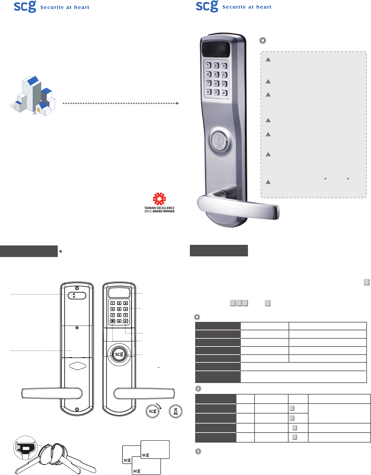
Product Overview The picture is for reference only.
Please check the actual model for specific functions.
Exterior plate
(Outside view)
Interior plate
(Inside view)
Setting Button
Up Button:
Use it to add new keycards/
PIN codes
Down Button:
Use it to delete keycards/
PIN codes
Battery Cover
Use the special tool provided
to open
Sensor
Keypad
PIN codes consist of 4~8
digits, numbers can be
repeated
Confirm/Exit Button
Select Button
Keyhole Cover
Horizontally position the
key and turn the keyhole
cover 90 clockwise to
remove it then unlock with
the key
--Accessories--
Emergency Override Key
3 keys provided per lock RFID Keycards
Door Lock Status
Type
Administrator
User
Single-Entry User
Volume
Quantity Function No. Instruction
4 sets
94 sets
1 set
1 set
Add/Modify/Delete
Unlock the door
Can be used only
once
Sound volume
Unlocking Keycards or PIN codes.
Keycards or PIN codes be used
only once.
Types of No.
Status
Operation Successful
Operation Failed
Enter/ Exit Setup Mode
Low Battery
Door Opened Indication
Door Closed Indication
Light
Blue
Red
Blue / Red
Red
1 beep
3 beeps
2 beeps
5 continuous beeps
Sounds
1 beep after the right Keycard or PIN code that the lock is open.
After depressing the lever, the door is locked 1.5 seconds after
the lever comes back to the horizontal position.
Unlocking Methods
Notice
.The factory default admin. PIN code is 123456. It is highly recommended to change the
admin. code upon installation of the lock.
.Only one PIN code or one Keycard can be set per No. of location.
.Please turn to the last page to restore to the factory default settings.
.There is no need to reset PIN codes or Keycards after battery replacement.
•The setup mode cannot be entered during the passage mode.
1.Mechanical Key : Horizontally position the key and turn the keyhole cover 90 degrees
clockwise to remove it then unlock with the key.
2.Keycard : Press any button to enter the system, simply place the RFID card to the sensor.
3.PIN Code : Press any button to enter the system, enter assigned PIN code and press
to confirm.
4.Passage Mode : Place the RFID card to the sensor or enter assigned PIN code and press
. Press to lock.
#
*#
*
#
00~03
*
04~97
*
98
*
99
*
Electronic RFID & Keypad Door Lock
SKR600
Operation Manual
SKR600 Specification
Dimension -- Panels:
290(H) x 70(W) x 72 (D)-(mm)
Approximate Weight:4520 g
Use 4AA Alkaline batteries (1.5V)
Others:
RFID Sensor
Digital Pad (Metal & Waterproof)
Door Thickness:
45mm ~ 55mm
56mm ~ 80mm
Standard US Mortise Lockbody
Temperature:-10 C ~ 70 C
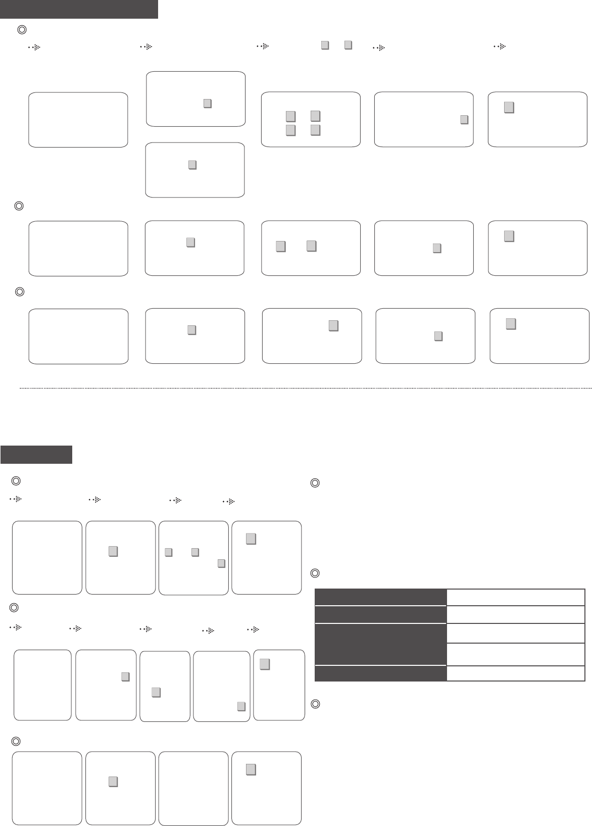
Enter the Setup Mode
Enter the
Setup Mode
Administrator Recognition
Administrator
*
Press the No. 00~ 99
*
Press
the No.
Enter
Exit Setup Mode
Exit Setup Mode
PIN Code/ RFID Keycard Setup
1. The admin. and user PIN code cannot be 000000/111111/123456.
2. Blue light flashes if the setup location has been occupied.
Notice
3. 3 beeps (red light) mean operation failure.
4. If no actions are taken over 5 seconds during the setup mode, the system will exit
automatically with two beeps (blue light).
User Setup
1345
2#
Press the Up Button on
the back of the lock for 2
seconds until hear two
beeps.
Input admin. PIN code and
then press to confirm or
position the admin. card to
the sensor.
#04 ~ 97
**
Press the No. Enter the intended PIN
code (consistsof 4-8 digits),
and then press to
confirm or position the card
to the sensor.
#
Single-Entry User Setup
Other Setup
User Deletion
1 2 3 4
#
Press the Down
Button on the
back of the lock
for 2 seconds
until hear two
beeps.
Input admin. PIN
code and then
press to confirm
or position the
admin. card to the
sensor.
#
Enter the No. you
intend to delete
( 01 ~ 97),
and then press
to confirm or
position the card.
#
**
Volume Setup
1 2 3 4 5
#
Press the Up
Button on the
back of the lock
for 2 seconds
until hear two
beeps.
Input admin.
PIN code and
then press
to confirm or
position the
admin. card to
the sensor.
#
Press
the No.
99
*
Press
00(mute),
01(low),
02(medium) or
03(loud), and
then press
to confirm.
#
1 2 3 4
All User Deletion
#
Press the Down
Button on the
back of the lock
for 2 seconds
until hear two
beeps.
Input admin. PIN
code and then
press to confirm
or position the
admin. card to the
sensor.
#
Press the Down
Button on the back
of the lock for 5
seconds until hear
a continuous beep
and two short beeps
mean successful
reset.
Factory Default Setting
Problem
Continuous beeps after successful
operation
No reaction when entering Keycards/
PIN codes
Light doesn’t go off
Low battery alert. Please replace
batteries immediately.
Batteries are dead. Please use
the key to unlock.
Consecutive Keycards/PIN codes entry
errors. Pleae try again after 1 minute.
Replace batteries.
Indication
Troubleshooting
Important Notes
1345
2#
Press the Up Button on
the back of the lock for 2
seconds until hear two
beeps.
Input admin. PIN code and
then press to confirm or
position the admin. card to
the sensor.
#Press the No. 98
*
Enter the intended PIN
code (consistsof 4-8 digits),
and then press to
confirm or position the card
to the sensor.
#
Administrator Setup
- First time setup
1345
2#
2
Press the Up Button on
the back of the lock for 2
seconds until hear two
beeps.
Input the factory default
admin. PIN code (123456)
and then press to
confirm.
#
Input admin. PIN code and
then press to confirm or
position the admin. card to
the sensor.
#
00/ 01
02/ 03
**
**
Press the No. Enter the intended admin.
PIN code (consists of 4-8
digits), and then press
to confirm or position the
admin. card to the sensor.
#
- Admin. already setup
1. Remove one battery.
2. Next, while continuously pressing the two buttons on the back, reinstall the
battery.
A continuous beeps (red light) and a short beep (blue light) after successful
operation.
1. If the Keycard is lost, please delete it right away.
* Notice:The administrator (*00) can’t be deleted individually.
2. Please use alkaline batteries only. Do not mix using old and new batteries.
3. The battery leakage will cause damage of the product. Please make
regular inspections of battery leakage.
4. Use a clean and dry cloth to preserve the cleanliness of the product. Do
not use alcohol or othe rchemical agents.
5. If you encounter any problems, please refer to the user manual first. If you
still have questions, please feel free to contact us or email us.
Enter the Intended PIN
Code or Card
Recognition
Enter the
Setup Mode
Administrator Enter Exit
Setup Mode
Recognition
Federal Communication Commission Interference Statement
This equipment has been tested and found to comply with the limits for a Class B digital device,
pursuant to Part 15 of the FCC Rules. These limits are designed to provide reasonable protection
against harmful interference in a residential installation.
This equipment generates, uses and can radiate radio frequency energy and, if not installed and
used in accordance with the instructions, may cause harmful interference to radio
communications. However, there is no guarantee that interference will not occur in a particular
installation. If this equipment does cause harmful interference to radio or television reception,
which can be determined by turning the equipment off and on, the user is encouraged to try to
correct the interference by one of the following measures:
. Reorient or relocate the receiving antenna.
. Increase the separation between the equipment and receiver.
. Connect the equipment into an outlet on a circuit different from that to which the receiver is
connected.
. Consult the dealer or an experienced radio/TV technician for help.
FCC Caution: To assure continued compliance, any changes or modifications not expressly
approved by the party responsible for compliance could void the user's authority to operate this
equipment. (Example - use only shielded interface cables when connecting to computer or
peripheral devices).
This device complies with Part 15 of the FCC Rules. Operation is subject to the following two
conditions:
(1) This device may not cause harmful interference, and
(2) This device must accept any interference received, including interference that may cause
undesired operation.