Sungworld Electronics SW-E102 UM BC User Manual
Shenzhen Sungworld Electronics Co., LTD. UM BC Users Manual
UserManual.wiki
>
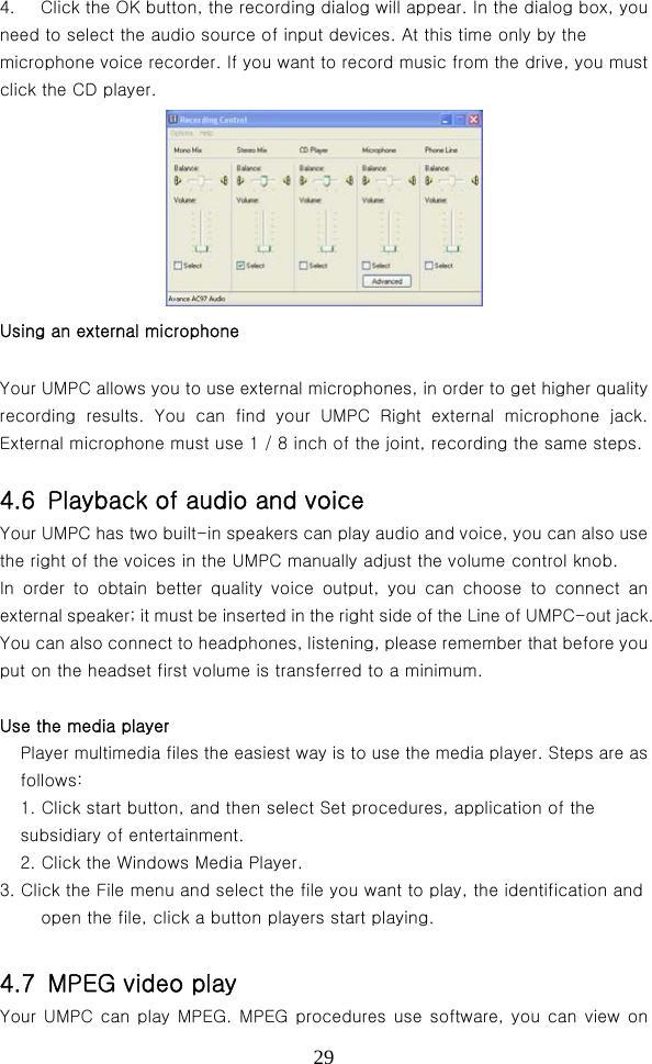
Sungworld Electronics
>
SW E102 User Manual
Users Manual
Navigation menu
Upload a User Manual
Namespaces
Wiki Guide
HTML
PDF
Info
Views
User Manual
Discussion / Help
Navigation
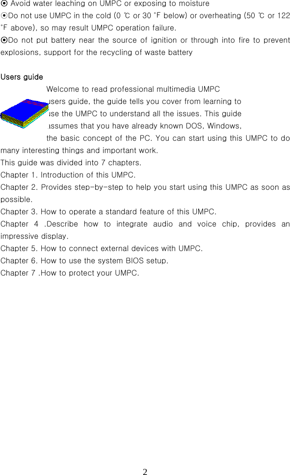
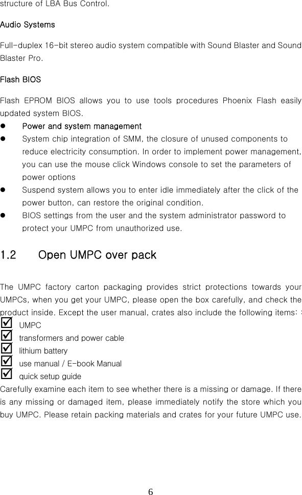
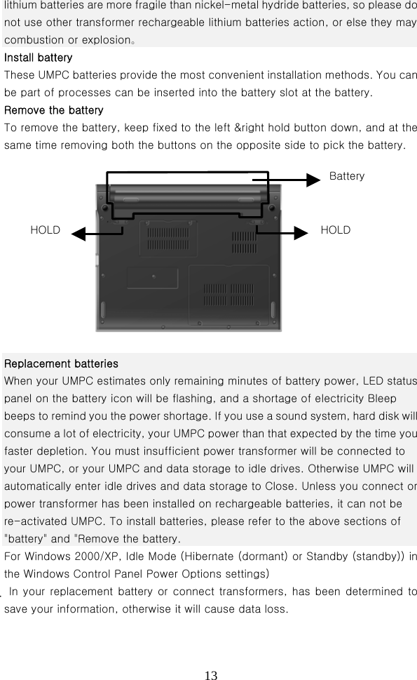
![37Boot Device Priority sub-manual This section is used to set up the boot disk driveing boot sequence, the use of <+> or <-> options will be set up before the shift, and after the shift. Hard Disk Drives sub-menu This section is used to set up the hard drives which will be set to boot disk drives, the default values for the open settings: [drive models] [Disabled] Removable](https://usermanual.wiki/Sungworld-Electronics/SW-E102/User-Guide-985277-Page-37.png)
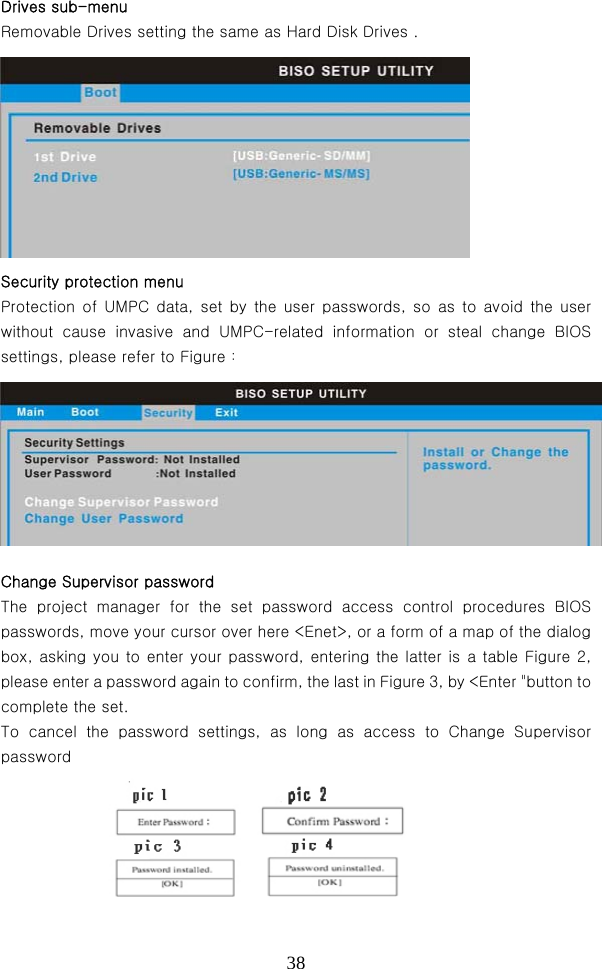
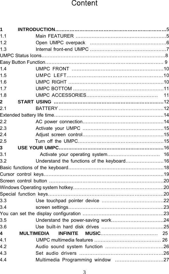
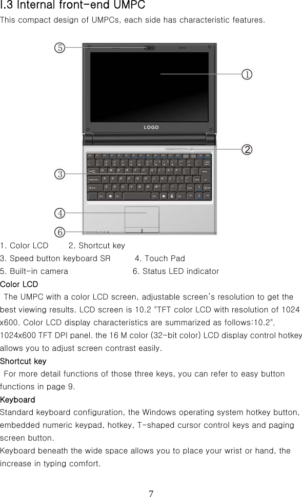
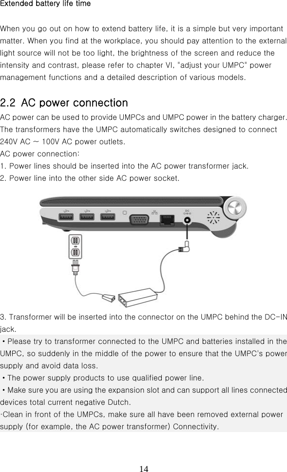
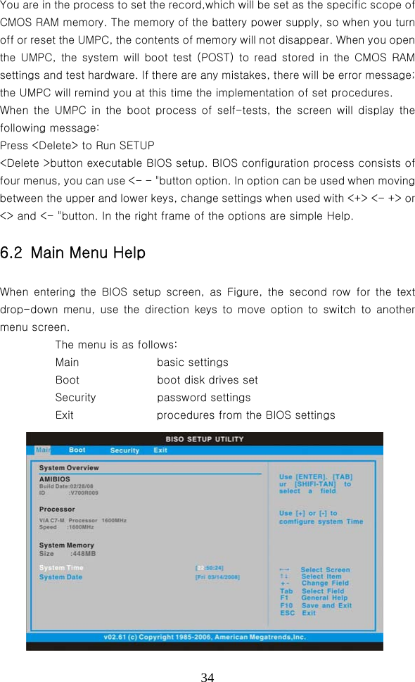
![39Options, a dialog box in Figure, do not enter a password directly <Enter "button, the dialog box in Figure 4, that is, cancellation password. Change User password The project is to set up user passwords, control system and boot into the BIOS setup program password, enter a user password to access BIOS procedures subject to the purview of the User Access Level on the settings. The cursor will move here <Enter>, or a form of a map of the dialog box, asking you to enter your password, enter the latter is a table Figure 2, you enter a password again to confirm password, last seen Figure 3, by <Enter> button to set up. Exit from the menu When you finish after all the BIOS settings from the menu to open, please enter the BIOS setup menu mode to leave, please refer to Figure: Saue Changes and Exit When you finish all the BIOS settings, select the item to confirm all settings to stored value into CMOS memory, click <Enter "button that is a dialogue window Figure 5: Selecting [OK] will set up a deposit of CMOS memory and leave the BIOS settings; election [Cancel] to BIOS settings. Discard Changes and Exit If you want to give up settings, and left the BIOS setup program, please move your cursor here <Enter>, a dialogue window Figure 6:](https://usermanual.wiki/Sungworld-Electronics/SW-E102/User-Guide-985277-Page-39.png)
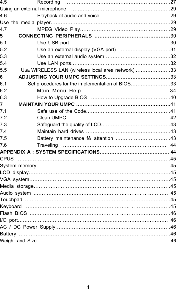
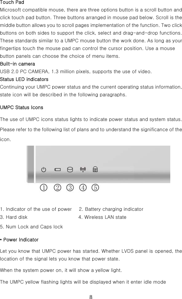
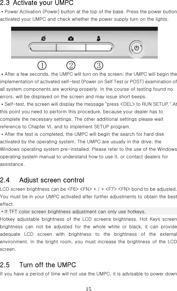
![40 Selecting[OK] will not change any settings and left BIOS settings; election [Cancel] to BIOS settings. Load Optimal Defaults If you want to give up settings, all settings will be the best value of the default values, I would be grateful if the cursor moved here <Enter>, a dialogue window Figure 7: Selecting [OK] will be the best value of all settings of the default values; elect [Cancel] to BIOS settings. 6.3 How to Upgrade BIOS Your UMPC use EPROM Flash BIOS chip, you can easily upgrade BIOS procedures. When you update BIOS, all the settings will be gone. Upgrade BIOS 1. BIOS Update will be inserted floppy disk machine. 2. Open the UMPC's power supply. 3. DOS prompt and type the following commands: A: ₩> audios / i XX.ROM (BIOS file name) 3. According <Enter "button BIOS implementation of this tool, systems implementation End after this procedure. 5. Re-activated by pressing any key UMPC. Please contact your dealer the latest BIOS upgrade files of the relevant information.](https://usermanual.wiki/Sungworld-Electronics/SW-E102/User-Guide-985277-Page-40.png)