Sunray TEchnology 8009 Transmitter User Manual
Shanghai Sunray Technology Co., Ltd. Transmitter
SRWF-8009 User manual RE0.5

ShangHai Sunray Technology Co.,Ltd
1 / 17
SRWF-8009 Wireless Meter Reading Module User
Manual
Version 2.0

ShangHai Sunray Technology Co.,Ltd
2 / 17
Content
1.Product Overview ................................................................................................................................. 3
2.Electric Characteristics and Parameter ................................................................................................. 3
3.Software Function ................................................................................................................................ 5
3.1. Measurement ............................................................................................................................ 5
3.2Communication Function ......................................................................................................... 8
3.3Valve Control Function ............................................................................................................ 8
3.4Battery voltage detection function ............................................................................................ 9
3.5Alarm function ....................................................................................................................... 10
4Brief Introduction of Compatibility..................................................................................................... 11
4.1. Pulse Closing Time Requirements ........................................................................................... 11
4.2.Pulse Number Requirements ................................................................................................... 11
4.3. Valve Requirements ................................................................................................................. 11
5Structure and Installation Size ............................................................................................................ 13
5.1.Structure of the Module .......................................................................................................... 13
5.2.Installation Size of the Module ............................................................................................... 13
6.Communication Tools ........................................................................................................................ 14
6.1.Handheld Unit ........................................................................................................................ 14
6.2.WAMR NET SYSTEM .......................................................................................................... 14
7.Parameter setting ................................................................................................................................ 15
7.1.Brief Introduction of parameter setting software.................................................................... 15
7.2.Relative Terminology Explanation of Parameter Setting ....................................................... 15
8.Certificates ......................................................................................................................................... 15
8.1.Pass CE、ROHS、R&TTE Certificates ................................................................................ 16
8.2.Conform to the IP68 Standard. ............................................................................................... 16
9.Trouble Shooting ................................................................................................................................ 16
9.1.Common Malfunction ............................................................................................................ 16
9.2. Installation Reference ............................................................................................................. 17
ShangHai Sunray Technology Co.,Ltd
3 / 17
1. ProductOverview
SRWF-8009 is a Wireless Remote Cold Water Meter Module which passed RoHS
and meets CE certification, and supports two-way communication. It can remotely turn
on/off the valve via background management system. The Background management
system can read the meter maximally every 1.5S. Standby current is less than 30uA
when no interference. ER18505M battery (3.3A/h) will guarantee 11 years of working
time.
The modules would take on Anti-rust action for the Meter valve every 10 days to
prevent valve stuck during remote valve controlling. Conforming to the IP68 standard
test, the modules ensure well function even in humid environment.
Wireless Remote Water Meter Module can be compatible with Reed switch
metering sensor, Pairs measured at the Hall element sensor, Hall element metering
sensor, Photoelectric direct reading measurement sensor.
2. ElectricCharacteristicsandParameter
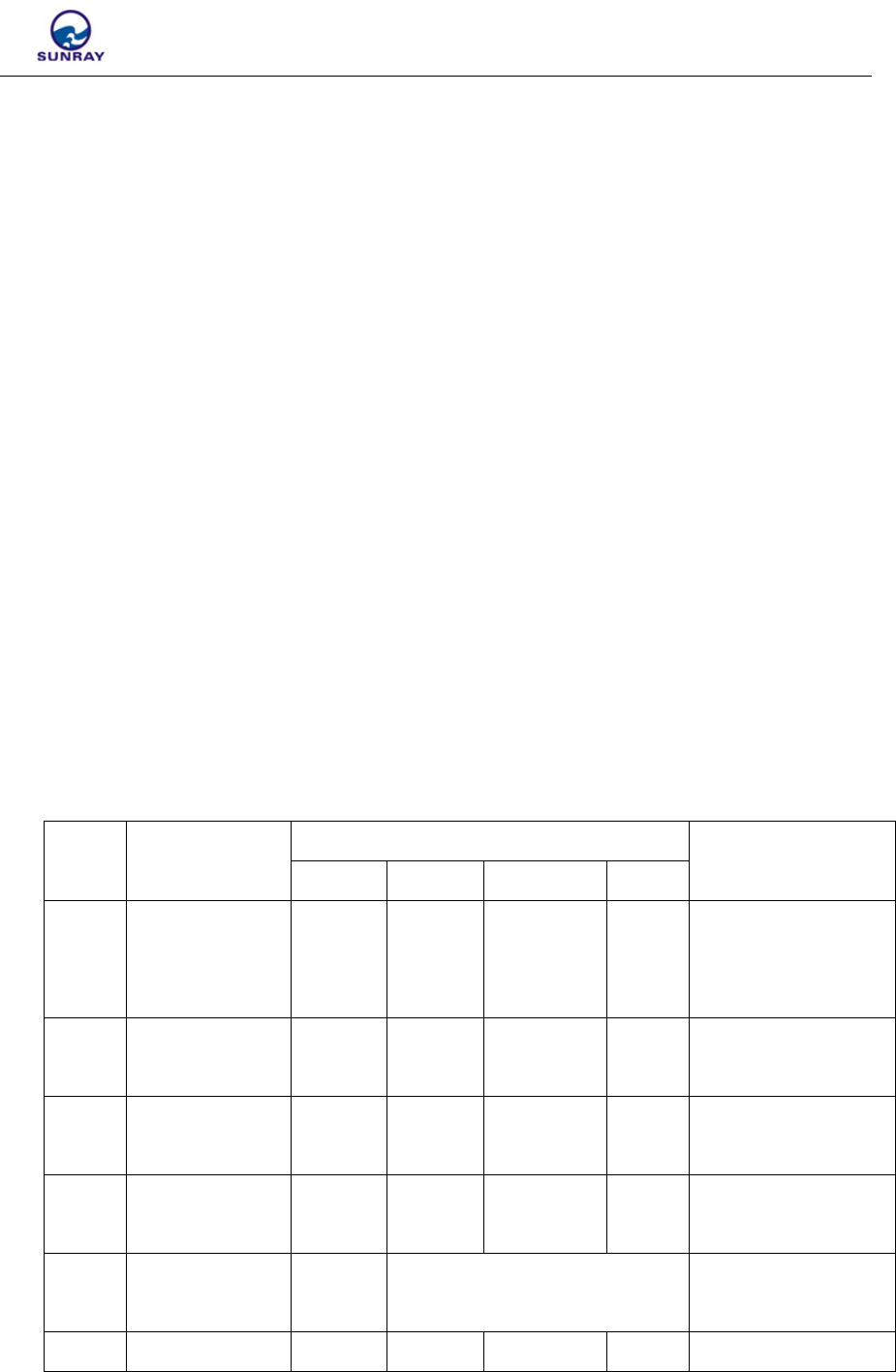
No. Description Parameter Notes
Unit Min Typical Max
1 Power supply V 3.2 3.6 4.0
Power type lithium
thionyl chloride
battery
2 Working
current uA 110 120
3 Reading
interval S 1 1.5
4 Working
temperature ℃ -25 25 65
5 Transmit
Frequency MHz 470
6 Reliable m 200 250 Open field

ShangHai Sunray Technology Co.,Ltd
4 / 17
Transmitting
Distance
7 Modulation
mode FSK
8 Channel 1 User can’t set the
channel
9 Lifetime year 10
10
Driving
current of
valve
mA 100 250
11
Reed switch
module pin
pull-up
resistors
KΩ 1.98 2 2.02
12
Hall
component pin
input
impedance
MΩ 60
13
Photoelectric
direct reading
module output
voltage
V 3.2 3.6 4
14
Photoelectric
direct reading
module output
current
mA 100
Photoelectric meter
power supply
15
UART Port
compatibility
level
V 3

ShangHai Sunray Technology Co.,Ltd
5 / 17
3. SoftwareFunction
3.1. Measurement
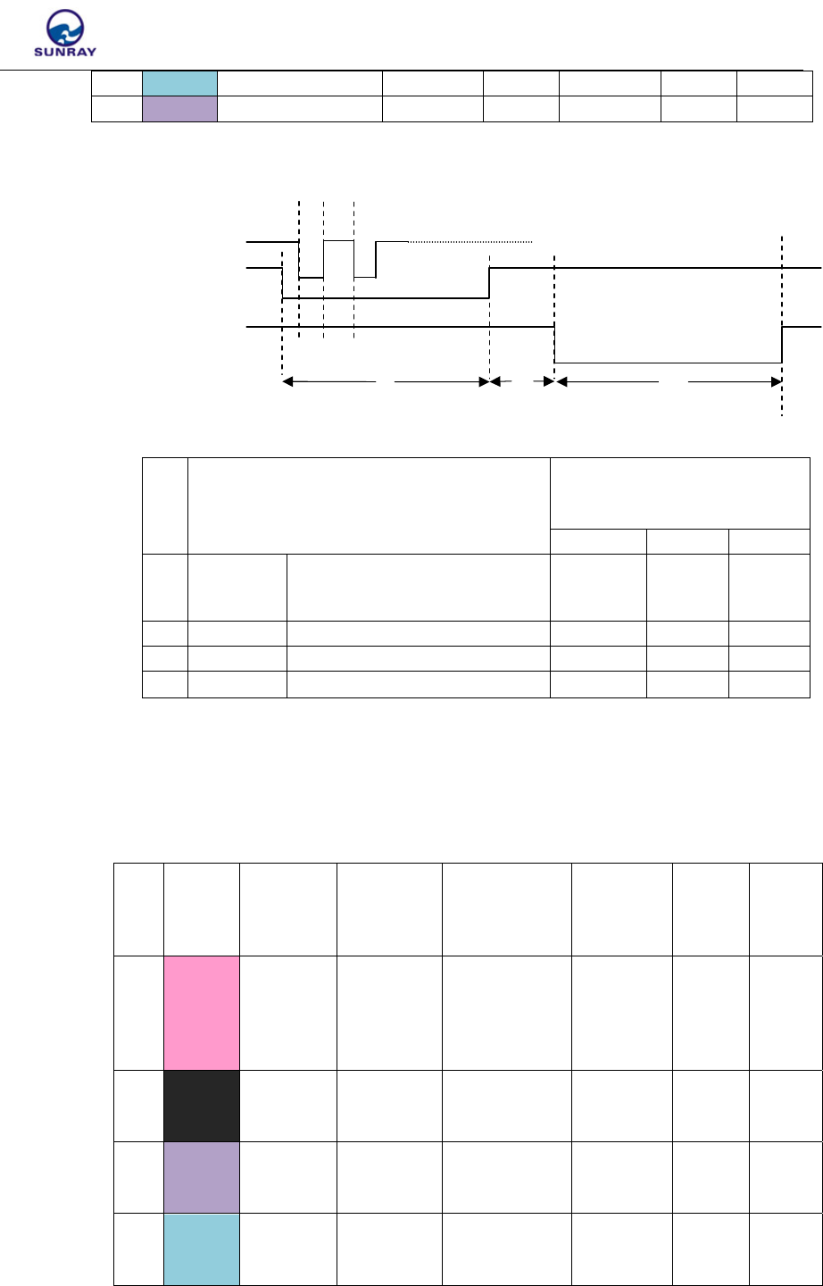
3.1.1. Double Reed Switch
3.1.1.1 Reed switch module pin connection
NO Wire Colour Pin Function
1 Black Common Ground
2 Purple Reed switch B
3 Green Reed switch A
3.1.1.2 A、B Reed switch pulse input timing diagram
A Reed switch
B Reed switch
t1 t2 t3
NO State Input low pulse time requirement
Min Typ Max
1 t1 A Closing Time 1.5S
2 t2 AB opening Time 1S
3 t3 B Closing Time 1.5S
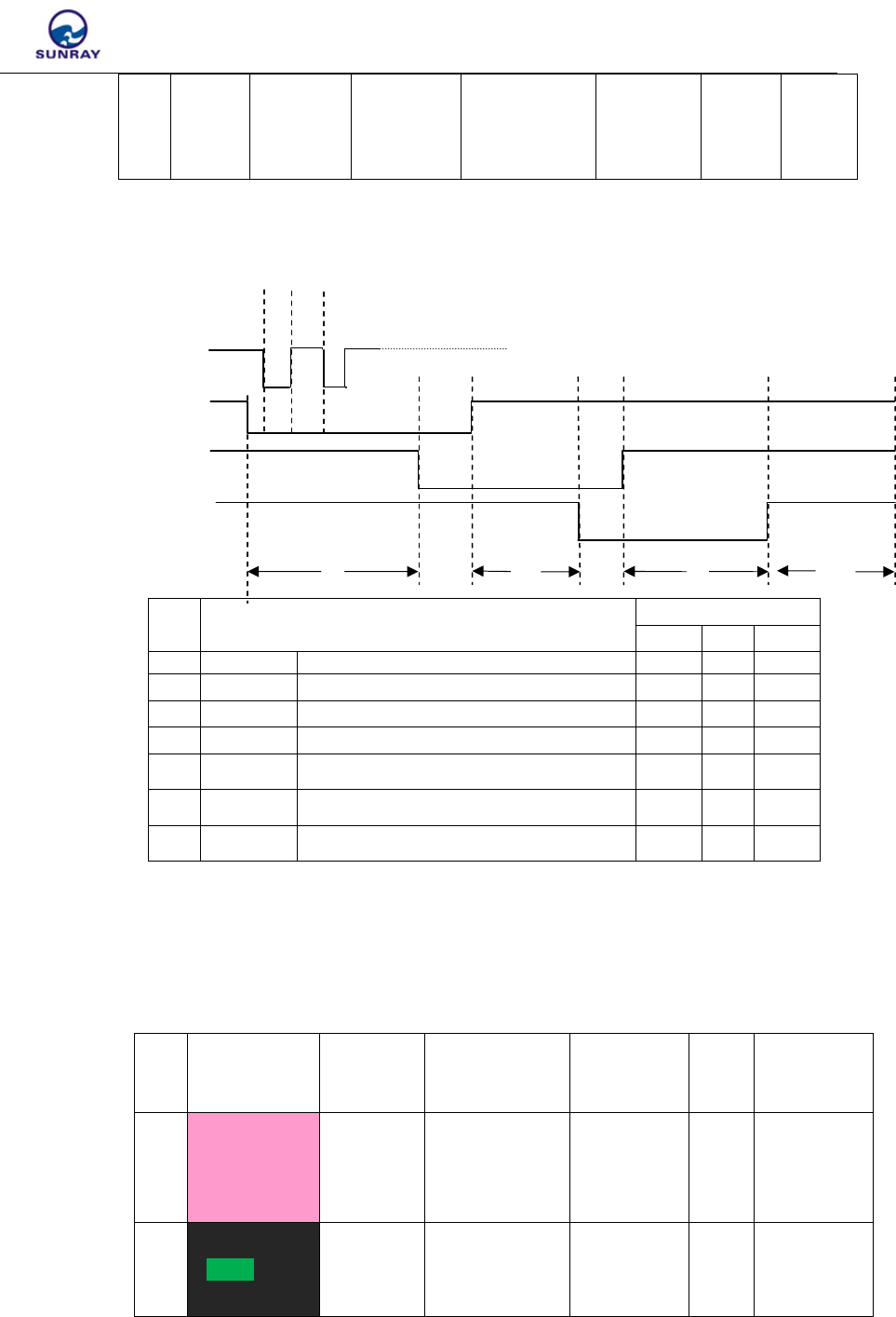
3.1.2. Double Hall Component
3.1.2.1 Hall module pin connection
NO Wire
Color Pin Function Test
Frequency
Max
driving
current
Power
supply
fre
q
uenc
y
Output
level
Input
level
1 Pink Hall power supply
terminal
1.5mA
(Vcc-
0.25)10Hz 3V
2 Black Common Ground
ShangHai Sunray Technology Co.,Ltd
6 / 17
3 Green Hall Input B 10Hz CMOS
4 Purple Hall Input A 10Hz CMOS
3.1.2.2 Parameter Requirements of Hall Component
VDD
Hall A t1 t2
Hall B
t3 t4 t5
NO State
Input low pulse time
requirement
Min Typ Max
1 t1 Hall meter head power supply
time
16mS
2 t2 Detection interval 100mS
3 t3、t5 Hall low time 1.5S
4 t4 Two Hall high time 1S
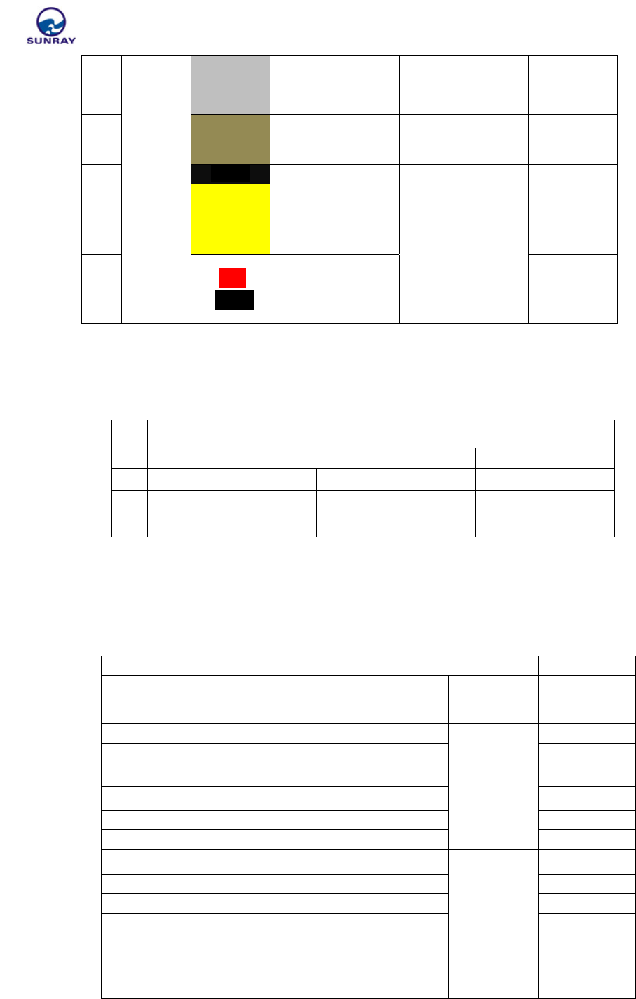
3.1.3. Three Hall Element
3.1.3.1 Double hall module pin connection
NO Wire
Color
Pin
Function
Test
Frequency
Maximal
driving
Current
Power
supply
frequency
Output
level
Input
level
1 Pink
Hall
power
supply
terminal
1.5mA(VCC-
0.25) 10Hz 3V
2 Black Common
Ground
3 Purple Hall Input
B 10Hz
CMOS
4 Green Hall Input
A 10Hz
CMOS
ShangHai Sunray Technology Co.,Ltd
7 / 17
3.1.1.4 Parameter of Hall Elements
VDD
Hall A t1 t2
Hall C
Hall B
t3 t4 t5 t6 t7 t8
NO State Input low pulse time
求
Min Typ Max
1 t1 Hall meter
p
ower su
pp
l
y
time 16mS
2 t2 Detection interval 100m
S
3 t3+t4 Hall A Low time 1.5S
4 t4+t5+t6 Hall C Low time 1.5S
5 t6+t7 Hall B Low time 1.5S
6 t8 Hall A、B、C High time 5S
7 t5 Hall A Low time to Hall B Low time 2S
3.1.4. Photoelectric direct reading
3.1.4.1 Photoelectric meter and the module pin connection
NO Wire Color Pin
Function
Maximum
driving current
Power
Supply
Fre
q
uenc
y
Outp
ut
level
Input level
1 Red
Module
power
supply
terminal
Depend on
meter
reading
frequency
3.6V
2 Green/Black
Controlled
public
ground
100mA
(VSS+0.2)
5 White Hall Input
C 10Hz CMOS

ShangHai Sunray Technology Co.,Ltd
8 / 17
3 White/Black Receive
data
3.6VCMOS
4 Yellow/Black Transmit
data 5mA
3VCMOS
3.1.4.2 Please see item 14, 15, 16 in Electric Characteristics and Parameter for detailed
interface parameter
3.1.4.3 For question related to UART Protocol, please contact the manufacturer.
3.2 Communication Function
3.2.1. Direct Reading
3.2.1.1. Handheld unit direct reading
3.2.1.2. Routing
3.2.1.2.1 Handheld unit reading though 1 layer routing
3.2.1.2.2 Handheld unit reading though 2 layer routing
3.3 Valve Control Function

ShangHai Sunray Technology Co.,Ltd
9 / 17
3.3.1. Wireless Valve control
3.3.1.1 Remotely open/close valve
When the modules received command of open/close valve, it first return
acknowledgment signal, then conduct valve-control action.
3.3.2. Automatically open/close valve to prevent rust
When the module is working in water meter, modules will turn on/off
valve automatically once every 10 days in order to prevent the valve to
get rusty.
3.3.3. Open/close valve during Magnetic attack
3.3.3.1. Double reed switch and double hall component meter
When two reed switch (Hall) turn off at the same time (low output),
module will report magnetic interference immediately and turn off the
valve. The module will open automatically after the magnetic attacks
disappeared for some time (depending on the setting).
3.3.3.2. Three Hall meter
When A Hall and C Hall give out the low output at the same time,
module will report magnetic interference immediately and turn off the
valve. The module will open automatically after the magnetic attacks
disappeared for some time.
3.4 Battery voltage detection function

ShangHai Sunray Technology Co.,Ltd
10 / 17
3.4.1.Power-on voltage detection
Once cold start-up, module will detect battery voltage once (load 47Ω
resisitance). Low voltage will be reported if battery voltage is below
3.15V
3.4.2. Voltage Detection while Continuous Working
The module loads the 47Ω resistance to detect the battery voltage every
48 hours, and it will report low voltage when battery voltage is below
3.15V. At the same time, voltage data is updated
3.5 Alarm function
3.5.1. Low voltage Alarm
“Low voltage mark” will be set once battery voltage is below 3.15V,
while system will not actively upload the alarm information.
3.5.2. Alarm during magnetic attack
When magnetic attack detection function of module is enabled, it will
report magnetic interference during magnetic attach. The alarm
information and also upload alarm information according to uploading
enable status
3.5.3. Anti disassembling alarm
When detecting function for disassembling is enabled, it will report
“disassembling” during magnetic attach (detected continuous changes
from four direction of sensor), and it will also upload alarm information
according to uploading enable status
3.5.4. Valve failure alarm
When driver’s opening in place and closing in place are detected at the
same time before valve control or after valve control, module will report
failure in place and will not actively upload alarm information,

ShangHai Sunray Technology Co.,Ltd
11 / 17
4 BriefIntroductionofCompatibility
4.1. Pulse Closing Time Requirements
See relevant introduction in software functions for details.
4.2. Pulse Number Requirements
Modules support,three pulse modes.
1 pulse for 1 cubic meter,
10 pulse for 1 cubic meter,
100 pulse for 1 cubic meter.
4.3. Valve Requirements
4.3.1. Valve control driver connection mode
NO Va lve
Type
Wire
Color
Module & Pin
Function Relative feature Signal Type
1
Photoele
ctric
position
valve
Yellow
Positive pole
during opening
valve Maximal driving
Current 250mA
2
Red
/Blackla
ck
Negative pole
during opening
valve
3 Gray Opening in place Input Resistance
60MΩ
TTL
4 Brown Closing in place Input Resistance
60MΩ
TTL
5 Blue Controllable
ground
100mA(VSS+0.25
)
Re
d
3.6V
p
ower out
p
ut
Mechani
cal
position
valve
Yellow Positive pole
during opening
valve Maximum Driving
Current 250mA
Red
/Black
lack
Negative pole
during opening
valve
ShangHai Sunray Technology Co.,Ltd
12 / 17
Gray
Opening in place 3V Pull up 2K
Resistance switch value
Brown Closing in place 3V Pull up 2K
Resistance switch value
Blac
k
Common Ground
No
position
signal
valve
Yellow
Positive pole
during opening
valve Maximum Driving
Current 250mA
Red
/Black
Negative pole
during opening
valve
4.3.2. Valve control circuit parameters
NO Status Input low pulse time requirements
Min Typ Max
1 Valve control time unit:S 24
2 Valve control current unit:mA 250
3 Current when valve stuck unit:mA 1.5S 250
4.3.3. Supported valve type
NO Valve Type Support
Mode
1 Type of valve in place Closing valve when
Over current
Valve Type Support
2 Photoelectric in place Yes
Ball valve
Support
3 Photoelectric in place No Support
4 Mechanic in place Yes Support
5 Mechanic in place No Support
6 None in position Yes Support
7 None in position No Support
8 Photoelectric in place Yes
Pilot valve
Support
9 Photoelectric in place No Su
pp
ort
10 Mechanic in place Yes S u
pp
ort
11 Mechanic in place No Support
12 None in position Yes Support
13 None in
p
osition No Su
pp
ort
14 None in
p
osition Yes Electroma
g
Su
pp
ort

ShangHai Sunray Technology Co.,Ltd
13 / 17
15 None in position No netic valve Support
5 StructureandInstallationSize
5.1. Structure of the Module
5.2. Installation Size of the Module
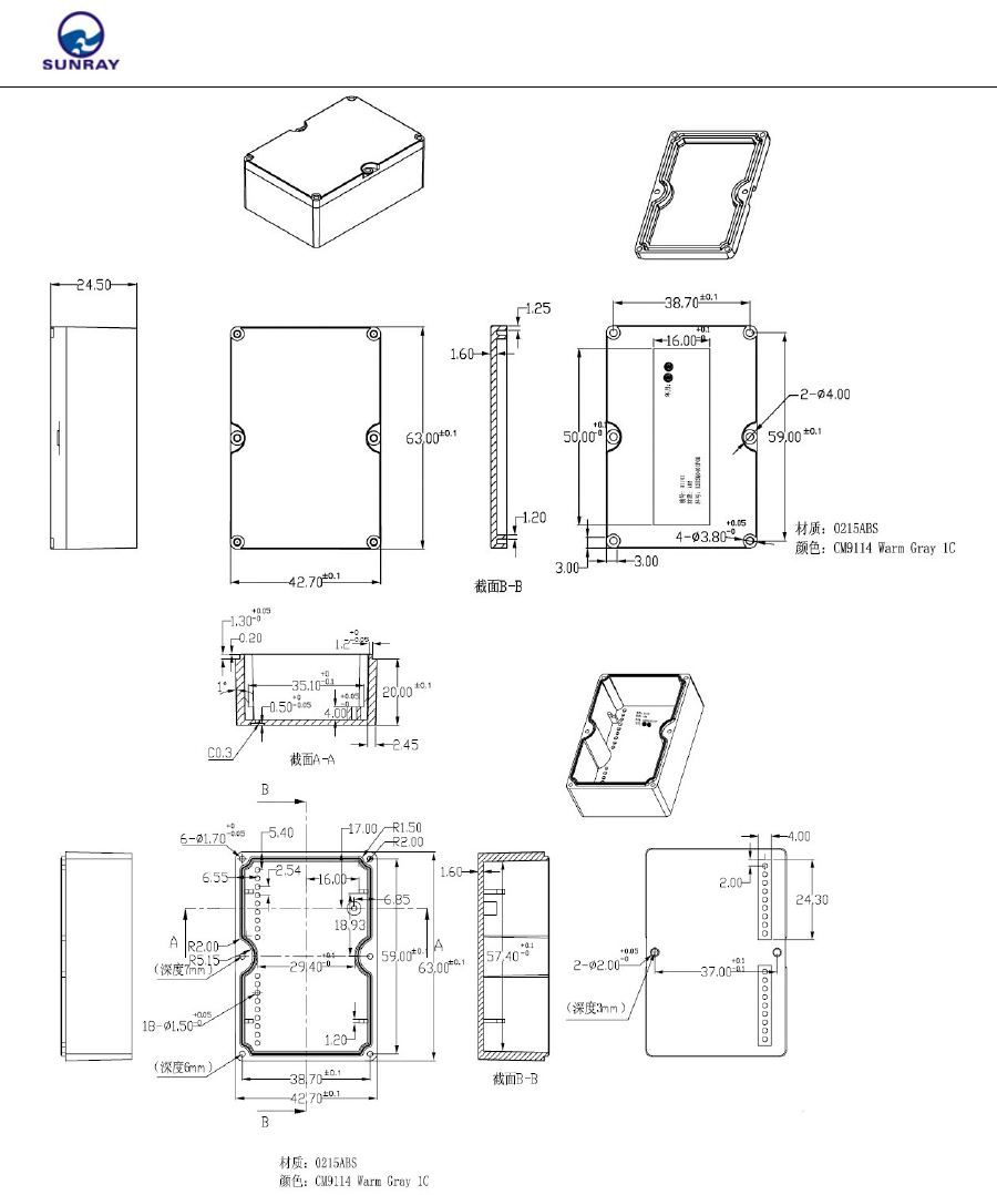
ShangHai Sunray Technology Co.,Ltd
14 / 17
6. CommunicationTools
6.1 . Handheld Unit
See “TP1100 User manual” for details
6.2. WAMR NET SYSTEM
See “WAMR NET SYSTEM User manual” for details

ShangHai Sunray Technology Co.,Ltd
15 / 17
7. Parametersetting
7.1. Brief Introduction of parameter setting software
See “WAMR NET SYSTEM User manual” for details
7.2. Relative Terminology Explanation of Parameter Setting
7.2.1. Meter ID:Set the meter ID,Maximum 10 BCD Code,e.g.1205130001
12 05 13 0001
Batch production,number of the day
Date,13 shows if it’s manufactured on 13th
Month,05 shows if it’s manufactured in May
Year,12 shows if it’s manufactured in 2012
7.2.2. Pulse number: corresponding pulse number for 1 m ³ water , can choose
among 1, 10, 100
7.2.3. Magnetic interference time: Valve will be opened after the set “magnetic
interference time”, the magnetic interference time is calculated when the
magnetic interference disappeared, the unit is: second. Set range: 0-127 S
default value is: 50 S
7.2.4. Usage: set the initial value of modules, namely, electronic number is the
same with what mechanical dial shows.
7.2.5. Valve control time: set the 100 milliseconds as base for the action time,
such as set 4S as the action time of valve for water meter module, a table
should be filled in 20 (range: 0-127). The actual action time of valve is 2
S*2 = 4 S, the maximum valve control time can be set as 25.4 S..
7.2.6. Meter type: Choose a meter type according to the application of module,
this module is only applicable to water meter.
7.2.7. Pulse type: Choose according to meter.type
7.2.8. Threshold current: mA is the unit. Parameters data is the result that the
actual value is devided by 2. For example, set threshold value as 120 mA,
60 shall be filled in, its range: 0-127, maximal threshold current that can be
set is 254 mA
8. Certificates

ShangHai Sunray Technology Co.,Ltd
16 / 17
8.1. Pass CE、ROHS、R&TTE Certificates
8.2. Conform to the IP68 Standard.
9. TroubleShooting
9.1. Common Malfunction
NO Problem Solution Notes
1 Unable to read the meter
Check whether the ID of the meter is
same to the one on label
Check whether the ID of the meter is
input correctly
Or if there is ID
setting of the meter
2 Unable to open/close the
valve
Check whether the cable of motor is
conversely connected
Common ground of in-position line is
open or not(apply for photoelectric
valve)
Check whether the motor is stuck
3
Can’t close the valve after
positioned(Large current
consumption)
Check whether there is in-position line
on valve
Check whether the in-position line is
reversely connected or not
Check if the set threshold current exceed
the range
4 Valve control not consistent
with command
Motor cable is reversely connected
5 Unable to measure Check whether the measure sensor type
is correct
6 Electrical and mechanical
inconsistencies
Check whether module pulse number is
consistent with the meter’s
Check whether the measure sensor of
meter failed
7 Low reading rate
Check whether the antenna of the module
is abnormal
Low battery
8 Abnormal Battery Pressure
Low battery Check whether the
battery type is correct
Return to manufacturer

ShangHai Sunray Technology Co.,Ltd
17 / 17
9.2.InstallationReference
A. The normal installation
(module antenna up and
parallel), maximize the
communication distance of
the module
B. Abnormal Installation,not
good for the communication
of the modules(shortens the
communication distance).
C. Abnormal Installation,not
good for the communication
of the modules, shortens the
communication distance.

ShangHai Sunray Technology Co.,Ltd
15 / 15
NOTE: This equipment has been tested and found to comply with the limits for a
Class B digital device, pursuant to part 15 of the FCC Rules. These limits are
designed to provide reasonable protection against harmful interference in a
residential installation.
This equipment generates, uses and can radiate radio frequency energy and, if not
installed and used in accordance with the instructions, may cause harmful
interference to radio communications. However, there is no guarantee that
interference will not occur in a particular installation. If this equipment does cause
harmful interference to radio or television reception, which can be determined by
turning the equipment off and on, the user is encouraged to try to correct the
interference by one or more of the following measures:
—Reorient or relocate the receiving antenna.
—Increase the separation between the equipment and receiver.
—Connect the equipment into an outlet on a circuit different from that to which
the receiver is connected.
—Consult the dealer or an experienced radio/TV technician for help.
This device complies with part 15 of the FCC Rules. Operation is subject to the
following two conditions:(1)This device may not canse harmful interference, and
(2)this device must accept any interference received,including interference that
may cause undesired operation.
Caution: The user is cautioned that changes or modifications not expressly
approved by the party responsible for compliance could void the user's authority
to operate the equipment.