Sunrise Telecom HTT01 Home Test Toolkit User Manual MAN 22461 001 A00 indd
Sunrise Telecom Inc. Home Test Toolkit MAN 22461 001 A00 indd
UserManual.wiki
>
Sunrise Telecom
>
HTT01 User Manual
Users Manual
Navigation menu
Upload a User Manual
Namespaces
Wiki Guide
HTML
PDF
Info
Views
User Manual
Discussion / Help
Navigation
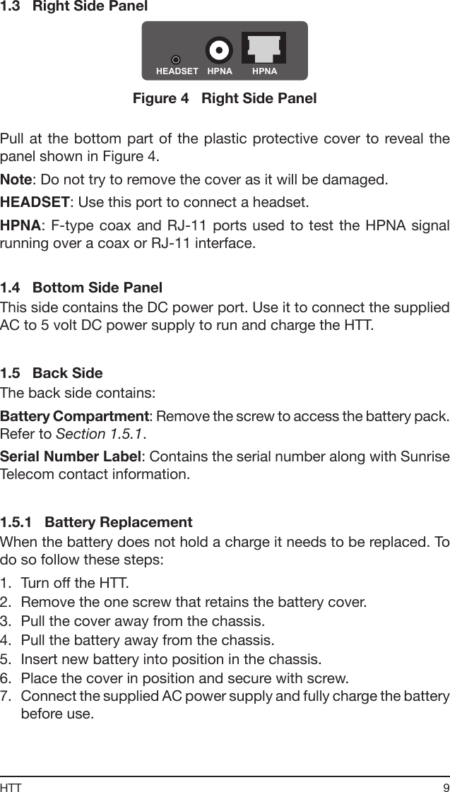

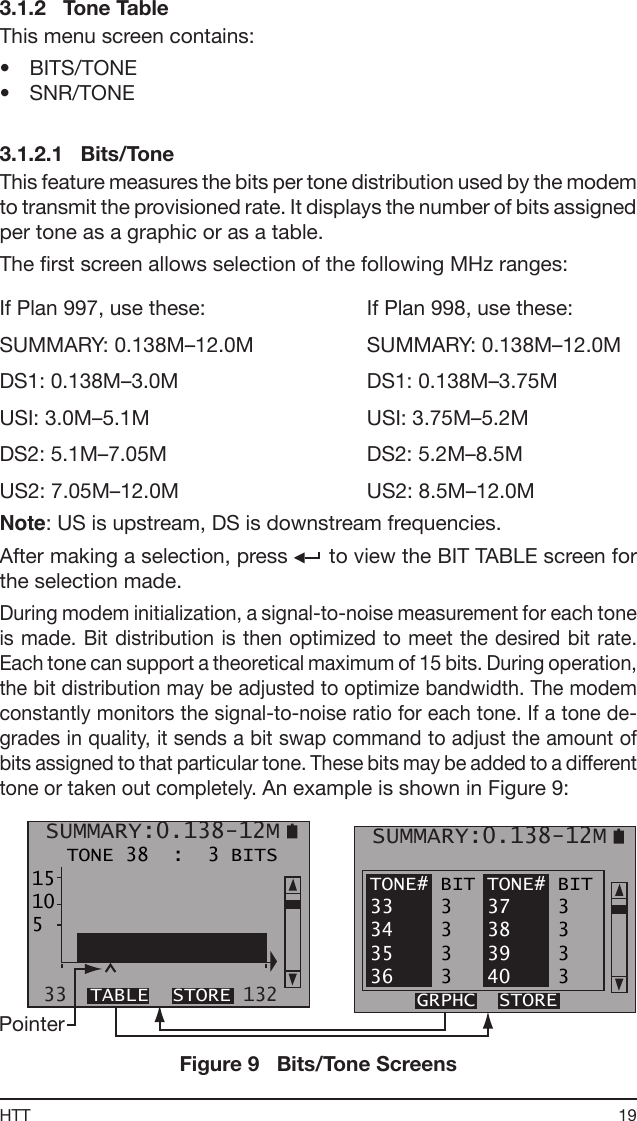
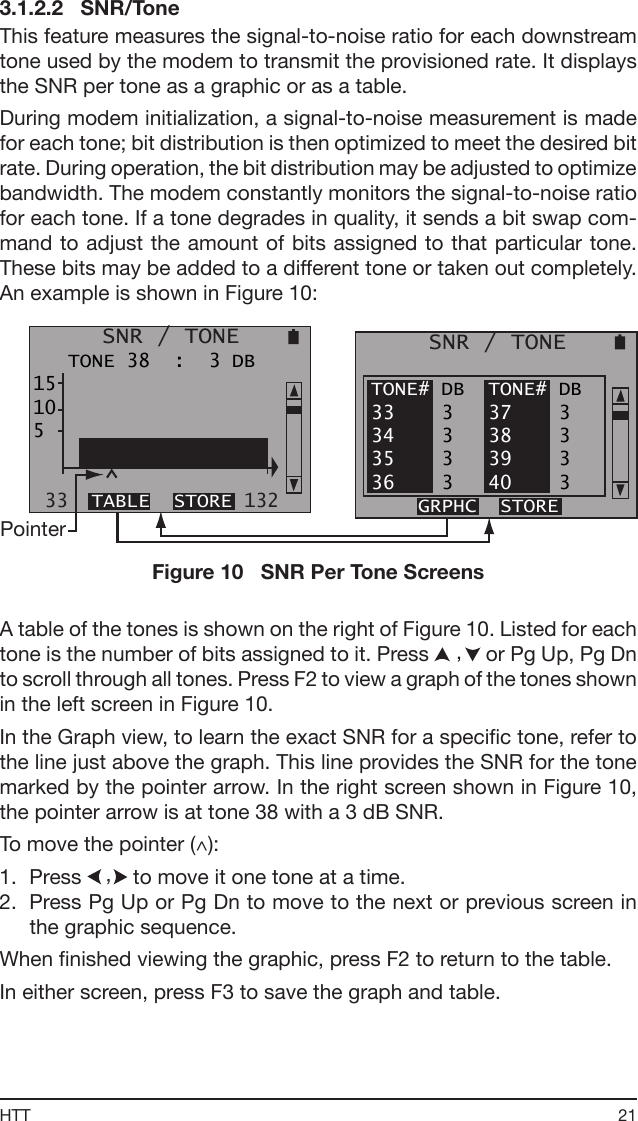
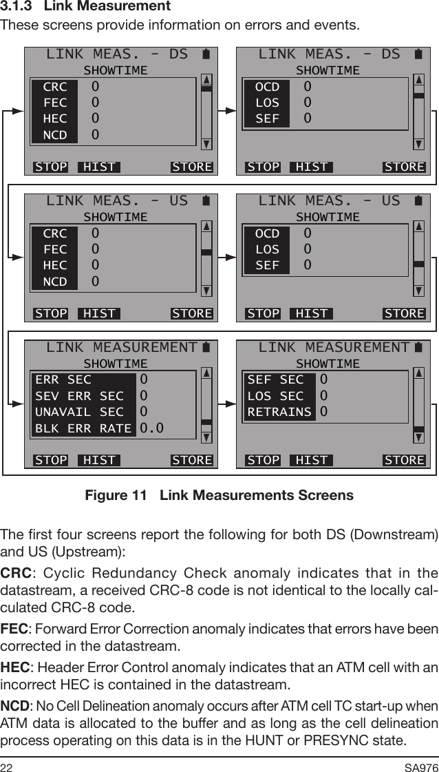
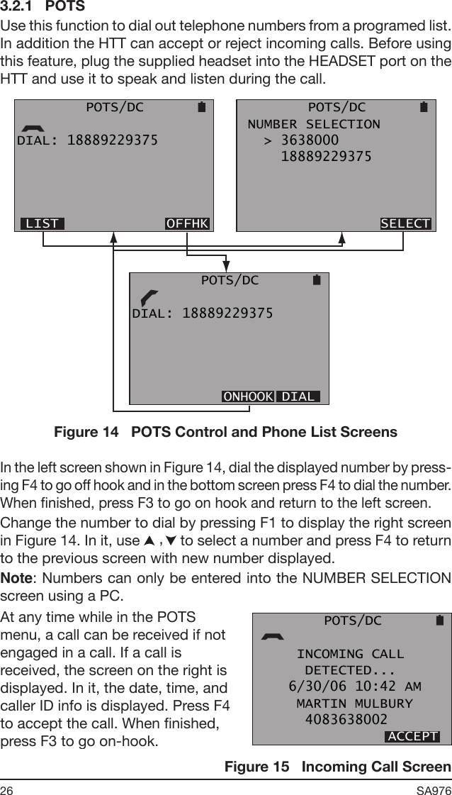
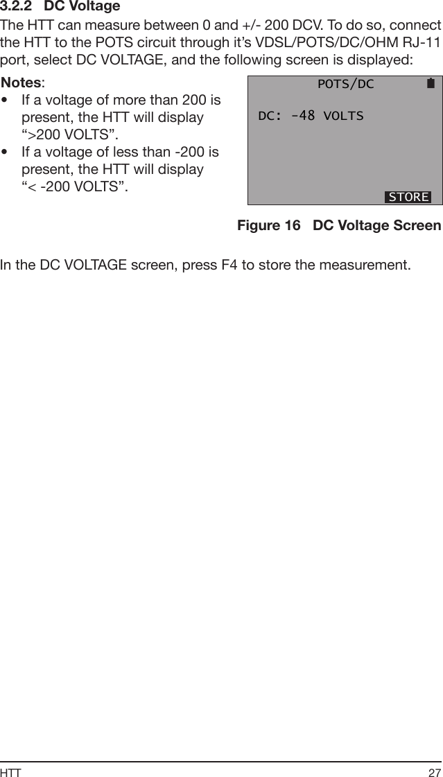
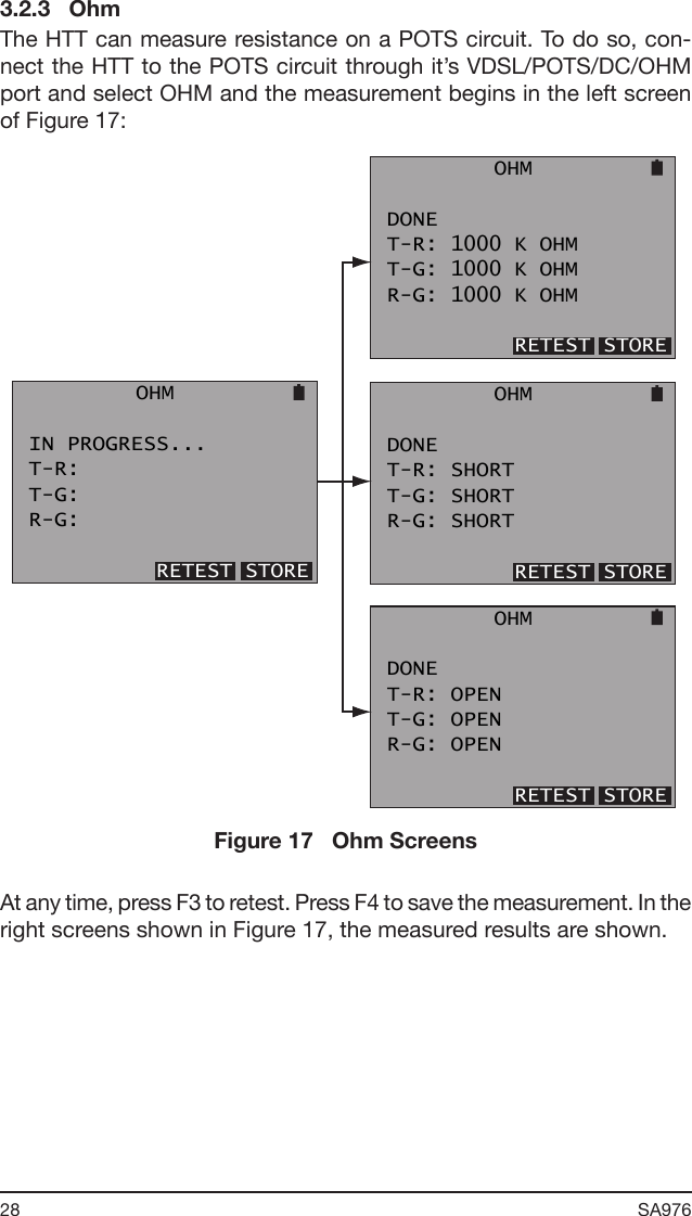
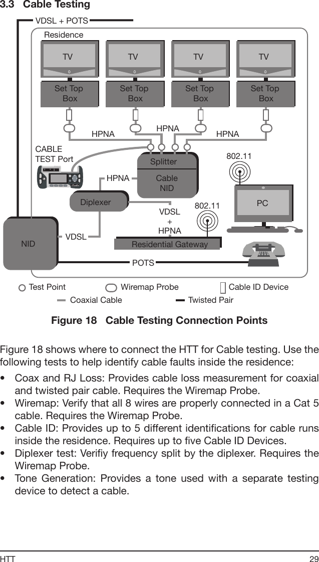
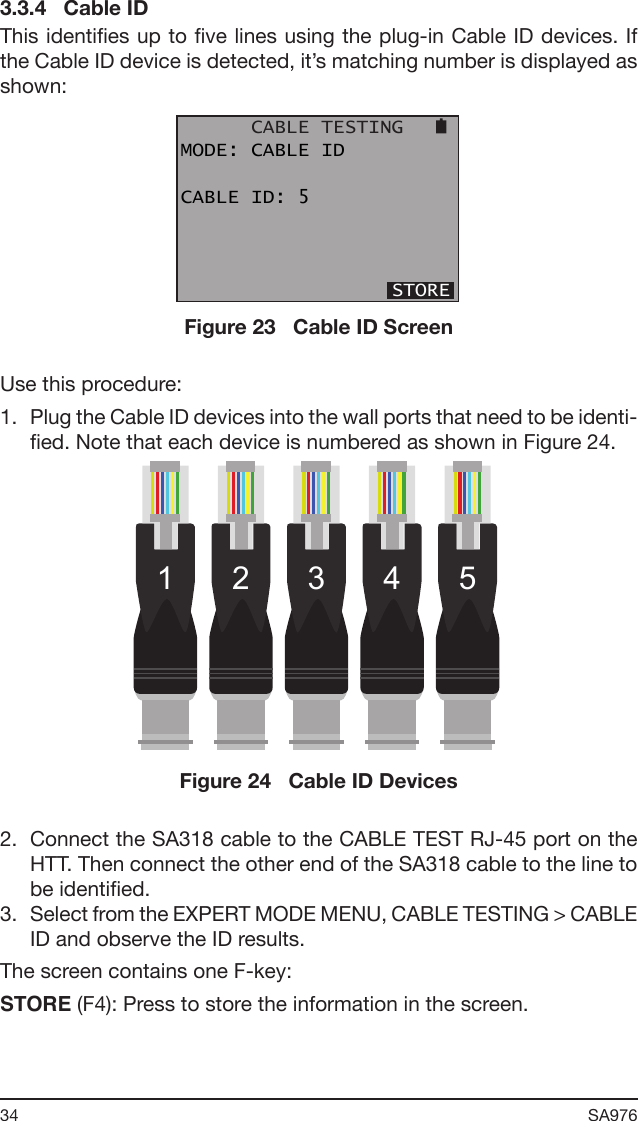
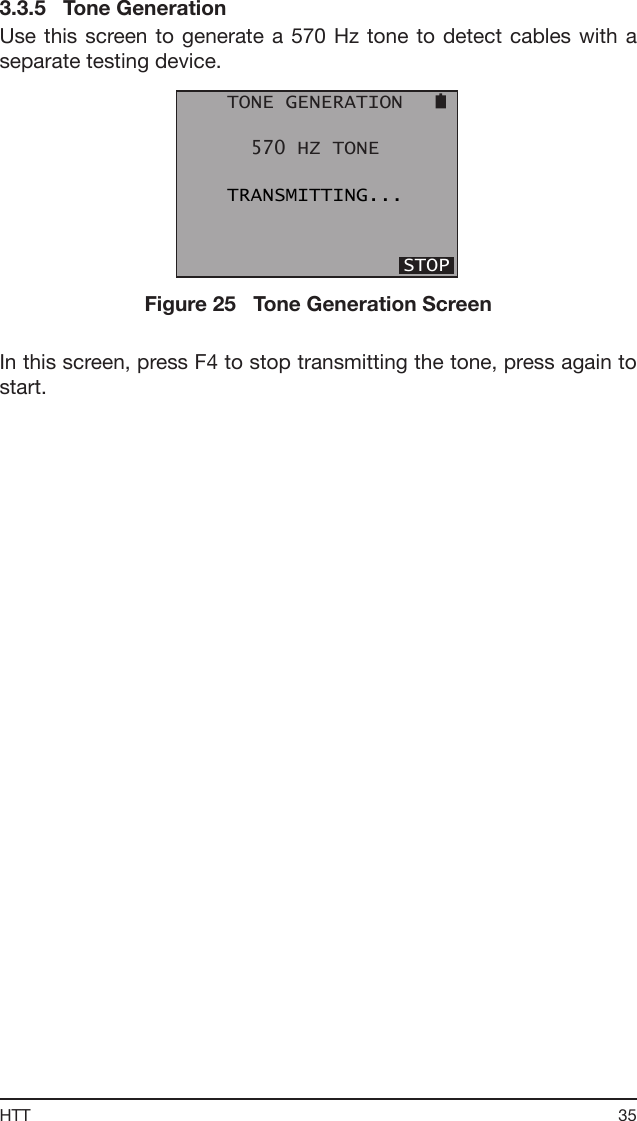
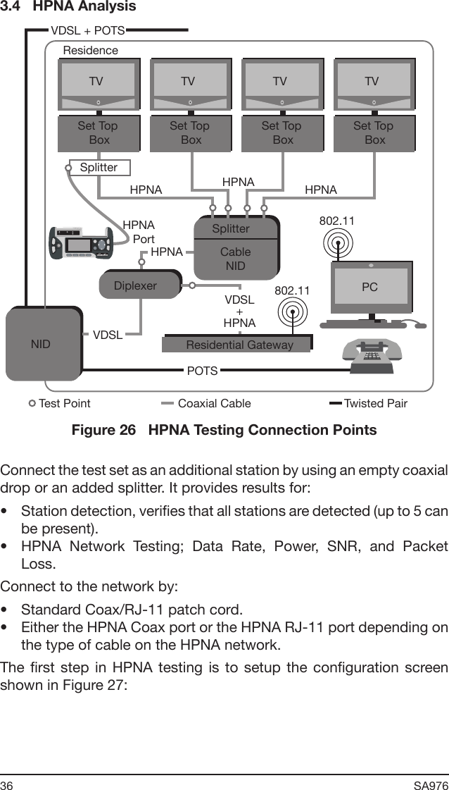
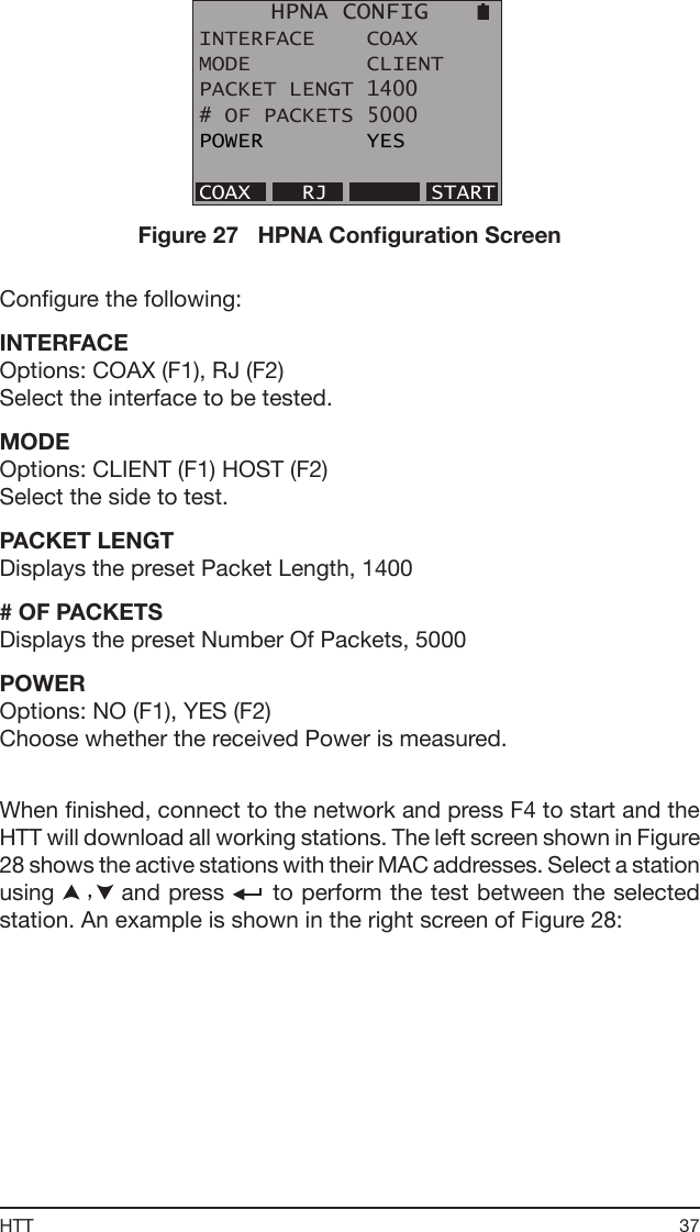
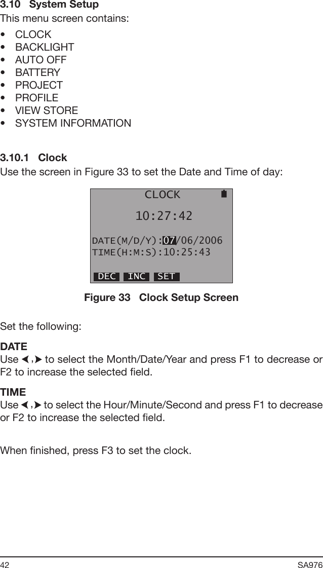
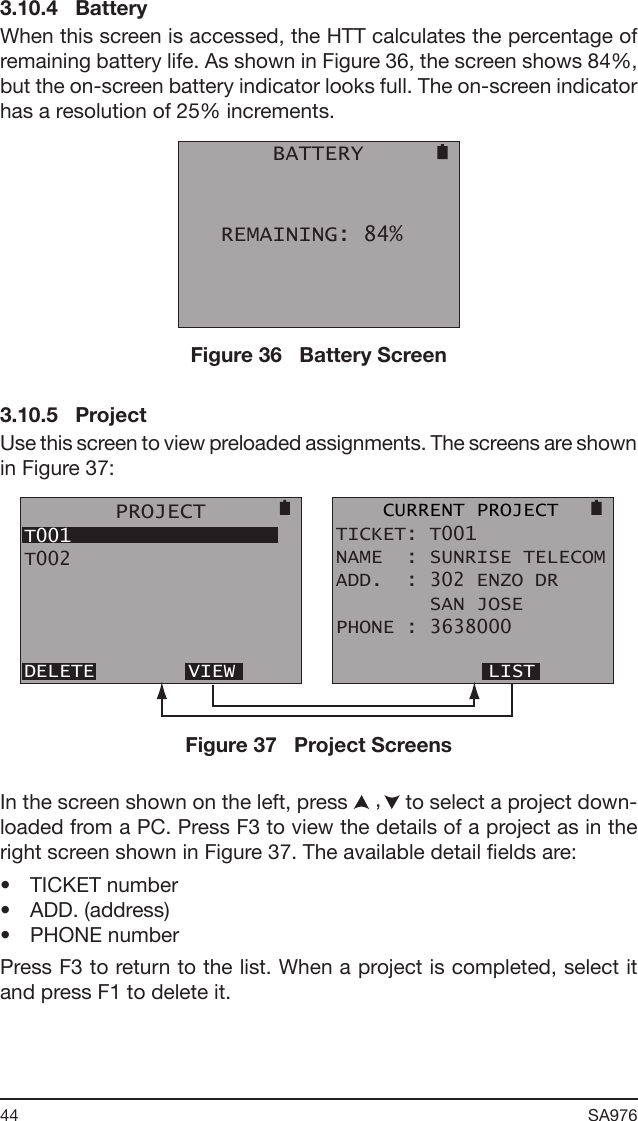
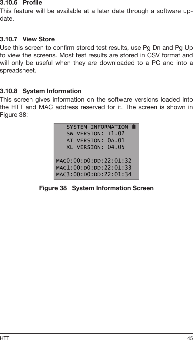
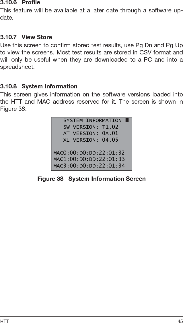
![43HTT3.10.2 BacklightUse the screen in Figure 34 to set the backlight on time and adjust the screen contrast: BACKLIGHT BACKLIGHT: ON[CONTRAST:USE ARROW KEYS] OFF 1 MIN 5 MIN ONFigure 34 Backlight Setup ScreenSet the following:BACKLIGHTOptions: OFF (F1), 1 MIN (F2), 5 MIN (F3), ON (F4)Choose the option that ts your needs.CONTRASTUse to adjust the screen contrast.3.10.3 Auto OffUse the screen shown in Figure 35 to control a shut off timer for the HTT: AUTO OFF AUTO SHUT OFF: OFF OFF 15 MIN 30 MINFigure 35 Auto Off Setup ScreenSet the following:AUTO SHUT OFFOptions: OFF (F1), 15 MIN (F2), 30 MIN (F3)Choose the option that ts your needs.](https://usermanual.wiki/Sunrise-Telecom/HTT01/User-Guide-684962-Page-43.png)