Sunrise Telecom HTT01 Home Test Toolkit User Manual MAN 22461 001 A00 indd
Sunrise Telecom Inc. Home Test Toolkit MAN 22461 001 A00 indd
Users Manual

1HTT
SUNRISE TELECOM
HT T
Home Test Toolkit
www.sunrisetelecom.com
User’s Manual
SA976
HTT
PASS/FAIL
BLUETOOTH
POWER
BATTERY
F1 F2 F3 F4
Pg
Up
Pg
Dn
MENU
AUTO ESC
SIGNAL
2 SA976
WARNING
Using the supplied equipment in a manner not specified by Sunrise Telecom may impair
the protection provided by the equipment.
End of Life Recycling and Disposal Information
DO NOT dispose of Waste Electrical and Electronic Equipment (WEEE) as unsorted
municipal waste. For proper disposal return the product to Sunrise Telecom. Please
contact our local offices or service centers for information on how to arrange the return
and recycling of any of our products.
• America: SUNRISE TELECOM INCORPORATED
302 Enzo Drive, San Jose, CA 95138, USA
Tel: +1-800-701-5208, +1-408-360-2200 Fax: +1-408-363-8313
Email: support@sunrisetelecom.com
• Germany: SUNRISE TELECOM GERMANY GmbH
Buchenstr. 10, D-72810 Gomaringen, GERMANY
Tel: +49-7072-9289-50 Fax: +49-7072-9289-55
Email: info@sunrisetelecom.de
• Europe: SUNRISE TELECOM PROTEL
Via Jacopo Peri, 41/c, 41100 Modena - ITALY
Tel: +39-059-403711 Fax: +39-059-403715
Email: europe.service@sunrisetelecom.it
• Asia: TAIWAN SUNRISE TELECOM Company Limited
21, Wu Chuan 3rd Road, Wu-Ku Hsiang, Taipei County, 248, Taiwan, R.O.C.
Tel: +886 2 2298 2598 Fax: +886 2 2298 2575
Email: support@sunrisetelecom.com
EC Directive on Waste Electrical and Electronic Equipment (WEEE)
The Waste Electrical and Electronic Equipment Directive aims to minimize the
impact of the disposal of electrical and electronic equipment on the environ-
ment. It encourages and sets criteria for the collection, treatment, recycling,
recovery, and disposal of waste electrical and electronic equipment.
MAN-22461-001 Rev B00
© 2006 Sunrise Telecom Incorporated. All rights reserved.
This device uses software either developed by Sunrise or licensed by Sunrise from third
parties. The software is confidential and proprietary. The software is protected by copy-
right and contains trade secrets of Sunrise or Sunrise’s licensors. The purchaser of this
device agrees that it has received a license solely to use the software as embedded in the
device, and the purchaser is prohibited from copying, reverse engineering, decompiling,
or disassembling the software.

3HTT
HTT
Introduction .................................................................... 5
Getting Around ...................................................................................5
1 Physical Description ................................................ 7
1.1 Front View ...................................................................................7
1.2 Top Side Panel ...........................................................................8
1.3 Right Side Panel .........................................................................9
1.4 Bottom Side Panel .....................................................................9
1.5 Back Side ...................................................................................9
1.5.1 Battery Replacement ...............................................................9
1.5.2 Battery Care and Storage ......................................................10
2 Auto Key .................................................................. 13
3 Expert Mode Menu ................................................. 15
3.1 VDSL VTU-R .............................................................................16
3.1.1 Current Status .......................................................................17
3.1.2 Tone Table .............................................................................19
3.1.2.1 Bits/Tone ............................................................................19
3.1.2.2 SNR/Tone ...........................................................................21
3.1.3 Link Measurement .................................................................22
3.1.4 Modem Setup ........................................................................24
3.2 POTS/DC/OHM ........................................................................25
3.2.1 POTS .....................................................................................26
3.2.2 DC Voltage ............................................................................27
3.2.3 Ohm .......................................................................................28
3.3 Cable Testing ............................................................................29
3.3.1 Coaxial Cable Loss ...............................................................31
3.3.2 RJ Cable Loss .......................................................................32
3.3.3 Wiremap ................................................................................33
3.3.4 Cable ID .................................................................................34
3.3.5 Tone Generation ....................................................................35
3.4 HPNA Analysis .........................................................................36
3.5 Wireless (802.11) ......................................................................39
3.6 SLM ..........................................................................................39

4SA976
3.7 Ethernet ....................................................................................40
3.8 PC Access ................................................................................41
3.9 Measurement Setup .................................................................41
3.10 System Setup .........................................................................42
3.10.1 Clock ...................................................................................42
3.10.2 Backlight ..............................................................................43
3.10.3 Auto Off ...............................................................................43
3.10.4 Battery .................................................................................44
3.10.5 Project .................................................................................44
3.10.6 Prole ..................................................................................45
3.10.7 View Store ...........................................................................45
3.10.8 System Information .............................................................45
4 General Information ............................................... 47
4.1 Customer Service .....................................................................47
4.2 Testing and Calibration Statement ...........................................47
4.3 Express Limited Warranty ........................................................48
Index ............................................................................. 51

5HTT
Introduction
Welcome to the HTT.
This User’s Manual describes the general structure of the HTT along
with it’s functions.
Contained within the shipping box are the following items:
HTT Test Set, Carrying Case, AC Charger, and User’s Manual: The
charger can simultaneously charge the battery and run the test set.
Cable ID Devices: These are used to identify coax or RJ runs into
each wall jack in the residence.
Wiremap Probe: Used primarily for Cable Loss and Wiremap test-
ing.
Cable Testing Cable: This is an RJ-45 to RJ-11/Coax connection cable
used for Cable Loss, and Cable ID testing. The single RJ-45 connects
to the HTT, and other ends connect to the circuit under test.
RJ-11 to clips Cable: Used for VDSL and POTS/DC testing.
RJ-11 to Coax Cable: Used for VDSL testing on Coax.
Coax Cable: Used for SLM or HPNA testing.
RJ-11 to RJ-11 Cable: Used for POTS/DC, VDSL, or HPNA testing
via an RJ-11 jack.
F-type Snap On Connector: Used on Coax cables to facilitate con-
nection.
F-type to F-type Barrel Adapter Coupler: Used to connect two ends
of male Coax cables together.
Headset: Used for POTS talk/listen applications.
Getting Around
The test set uses a hierarchical menu structure. From the test set’s
startup menu, make selections by pressing the appropriate part of
to move the cursor (
CURSOR SAMPLE 01:11:2006
). Once the selection has
been made, press or an indicated key.
Throughout this User’s Manual, the following shorthand is used to
indicate how to get to a particular menu function, such as: “SYSTEM
SETUP > CLOCK”, where the “>” means to press . To return to the
previous screen, press ESC.

6 SA976
FCC ID: UEBHTT01
This device complies with Part 15 of the FCC Rules. Operation is subject
to the following two conditions: (1) this device may not cause harmful
interference, and (2) this device must accept any interference received,
including interference that may cause undesired operation.
NOTE: This equipment has been tested and found to comply with the limits
for a Class A digital device, pursuant to Part 15 of the FCC Rules. These
limits are designed to provide reasonable protection against harmful in-
terference when the equipment is operated in a commercial environment.
This equipment generates, uses, and can radiate radio frequency energy
and, if not installed and used in accordance with the instruction manual,
may cause harmful interference to radio communications. Operation of
this equipment in a residential area is likely to cause harmful interference
in which case the user will be required to correct the interference at his
own expense.
Any changes or modifications not expressly approved by the party re-
sponsible for compliance could void the user’s authority to operate the
equipment.
Caution: Exposure to Radio Frequency Radiation.
To comply with FCC RF exposure compliance requirements, this device
must not be co-located or operating in conjunction with any other antenna
or transmitter.
7HTT
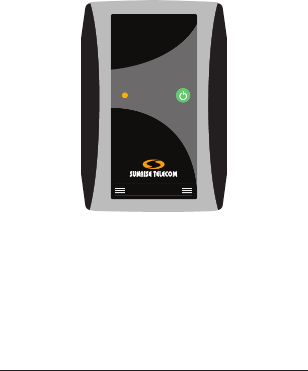
1 Physical Description
1.1 Front View
HTT
PASS/FAIL
BLUETOOTH
POWER
BATTERY
F1 F2 F3 F4
Pg
Up
Pg
Dn
MENU
AUTO ESC
Slide this cover to access the main port panel.
SIGNAL
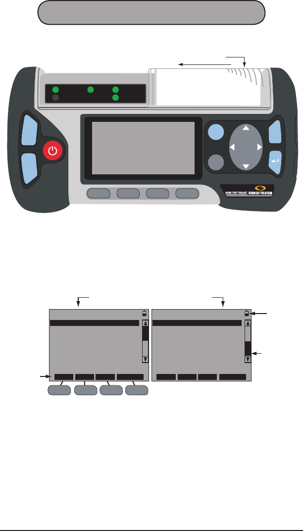
Figure 1 HTT Front View
Figure 1 shows the front view of the HTT. The major components
shown in this view are:
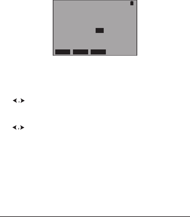
Display: This is an 8 line by 21 column LCD screen. Details of the
screen are show in Figure 2:
F1 F2 F3 F4
The scroll bar
indicates
additional
screens. Use
Pg Dn and Pg
Up to access.
EXPERT MODE MENU
VDSL VTU-R
POTS/DC/OHM
CABLE TESTING
HPNA ANALYSIS
WIRELESS (802.11)
VDSL POTS HPNA CABLE
EXPERT MODE MENU
SLM
ETHERNET
PC ACCESS
MEASUREMENT SETUP
SYSTEM SETUP
VDSL POTS HPNA CABLE
In this instance,
these F-keys
act as shortcuts
to a function.
The battery
indicates battery
life, in this case it
is about 1/2 full.
Press Pg Up or Pg Dn to access screens.
Figure 2 HTT Screen
LEDs:
PASS/FAIL: Indicates pass (green) or fail (red) results for a test.
SIGNAL: Indicates various signals specic to menu selection, such as
link up (green) and link down (red).
POWER: When the HTT is on, it is green.
BLUETOOTH: Indicates the presence of a Bluetooth network.
BATTERY: When the battery is low, it is red and the on-screen battery
indicator displays 1/4. It is green when charging.
8SA976
Keypad
Pg
Up
Pg
Dn
,
: Used to page up or page down through screens. Look for Pg
Up and Pg Dn in this manual.
: Use to power up/down the HTT. To turn on, press and hold for
3 seconds and the POWER LED illuminates green. To turn off, press
and hold for 5 seconds and the POWER LED will turn off. Look for
in this manual.
F1 F2 F3 F4
: These are used to perform selections shown on the
bottom of the screen as in Figure 2. Look for F1, F2, F3, F4, or F-keys
in this manual.
AUTO
: Starts a programed Auto Test sequence with on screen prompts.
Look for AUTO
in this manual.
MENU
: Use to display the EXPERT MODE MENU. Look for MENU in this
manual.
: Use to move the cursor in the indicated direction. Look for
in this manual.
ESC
: Use to move 1 step back in the menu. Look for ESC in this manual.
: Use to invoke a selection or action. Look for in this manual.
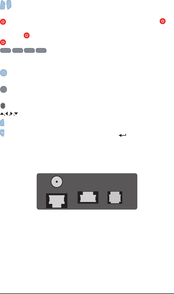
1.2 Top Side Panel
As shown in Figure 1, slide the transparent cover to access the main
port panel shown in Figure 3:
SLM
CABLE TEST
VDSL/
POTS/DC/OHM
ETHERNET
Figure 3 Main Port Panel
This panel contains:
SLM: Signal Level Meter Coax port used to test the quality of the signal
on the back of the STB (Set Top Box).
ETHERNET: Use this Ethernet port for basic Ethernet testing.
CABLE TEST: RJ-45 port used for Cable ID, Wiremap, Cable Loss
(over both twisted pair and Coax), and Diplexer testing.
VDSL/POTS/DC/OHM: RJ-11 port is used to test VDSL, POTS, and
check for DCV and OHM.

9HTT
1.3 Right Side Panel
HEADSET HPNA HPNA
Figure 4 Right Side Panel
Pull at the bottom part of the plastic protective cover to reveal the
panel shown in Figure 4.
Note: Do not try to remove the cover as it will be damaged.
HEADSET: Use this port to connect a headset.
HPNA: F-type coax and RJ-11 ports used to test the HPNA signal
running over a coax or RJ-11 interface.
1.4 Bottom Side Panel
This side contains the DC power port. Use it to connect the supplied
AC to 5 volt DC power supply to run and charge the HTT.
1.5 Back Side
The back side contains:
Battery Compartment: Remove the screw to access the battery pack.
Refer to Section 1.5.1.
Serial Number Label: Contains the serial number along with Sunrise
Telecom contact information.
1.5.1 Battery Replacement
When the battery does not hold a charge it needs to be replaced. To
do so follow these steps:
1. Turn off the HTT.
2. Remove the one screw that retains the battery cover.
3. Pull the cover away from the chassis.
4. Pull the battery away from the chassis.
5. Insert new battery into position in the chassis.
6. Place the cover in position and secure with screw.
7. Connect the supplied AC power supply and fully charge the battery
before use.

10 SA976
1.5.2 Battery Care and Storage
Observe these basic battery care procedures in order to avoid possible
damage to the battery and to maintain it’s performance.
WARNINGS
• Failure to observe the following procedures and precautions can
result in electrolyte leaks, heat generation, bursting, re, and seri-
ous personal injury.
• Battery electrolyte is a strong colorless alkaline solution, which is
extremely corrosive and will burn skin.
- If skin comes in contact with the electrolyte from the battery,
thoroughly wash the area immediately with clean water.
- If clothing comes in contact with the electrolyte from the battery,
discard the clothing.
- If any uid from the battery comes in contact with eyes, immedi-
ately ush thoroughly with clean water and immediately consult
a doctor. The electrolyte can cause permanent loss of eyesight.
• Keep the battery out of reach of children.
CAUTIONS
• Never dispose the battery in a re.
• Never heat the battery.
• Never strike or drop the battery.
• Do not apply water, or other oxidizing agents to the battery. This will
cause corrosion and heat generation. If the battery becomes rusted,
the gas release vent may no longer operate and cause the battery
to burst.
• Do not charge the battery using an AC adapter or charger not speci-
ed by Sunrise Telecom. Charge the battery only with the Sunrise
Telecom charger/AC adapter that came with your test set.
- If the battery is not fully charged after the battery charger’s
predetermined charging period has elapsed, stop the charging
process. Prolonged charging may cause leakage of battery uid,
heat generation, and or bursting.
- Charge the battery within a temperature range of 0°C (+32°F)
to +40°C (+104°F).
• Do not use the battery if it leaks uid or changes shape; otherwise
it may cause heat generation, bursting, and re.
• Do not short circuit the battery by connecting the positive (+) and
negative (-) terminals together with electrically conductive materials,
such as lead wires, etc.
• Do not connect the battery directly to a power source or the cigarette
lighter socket in a car. Use the optional specied cigarette lighter
charger from Sunrise Telecom.

11HTT
• Never disassemble the battery. Doing so may cause an internal
or external short circuit, or result in exposed material of battery
reacting chemically with the air. It may also cause heat generation,
bursting, and/or re.
• Never modify or reconstruct the battery pack. Protective devices
are built into the battery pack. If damaged, excessive current ow
may cause loss of control during charging or discharging of the
battery, which can result in leakage of battery uid, heat generation,
bursting, and/or re.
• When the battery operating time becomes much shorter than its
initial operating time even after recharged, the battery has reached
its end of life and should be replaced with a new one.
Extended Battery Storage
• Fully charge the battery before storing.
• Remove the battery from the test set as shown in Section 1.5.1.
• Do not store the battery in high temperatures, such as direct sunlight,
in cars during hot weather, or near any other heat source. This will
impair the performance and shorten the operating life of the battery,
and may cause battery leakage.
- For maximum battery life, store the battery between -20°C (-4°F)
and +30°C (+86°F).
• During storage, the battery will need to be regularly recharged. The
interval ranges from approximately 30 to 90 days at temperatures
between -20°C (-4°F) and +30°C (+86°F). In general the higher the
storage temperature the shorter the recharge cycle.
- To recharge, install the battery into the test set and use the sup-
plied Sunrise battery charger to recharge the battery.
- Charge the battery within a temperature range of 0°C (+32°F)
to +40°C (+104°F).
• After long-term storage, there is a possibility that the battery will not
fully recharge. To fully charge it, charge and discharge the battery
for a few times. Use the test set to discharge the battery.

12 SA976

13HTT
2 Auto Key
Press and hold for 3 seconds to power up the HTT. When the screen
shown in Figure 5 is displayed, press AUTO as indicated to perform
automated testing. The HTT will prompt you through all steps involved
in the test procedure from connection to the conclusion of the test.
S/N000102 VERSION T1.02
HTT
Home Test Toolkit
SUNRISE TELECOM
192.168.3.133
Press AUTO/MENU to START
HTT IP Address
Figure 5 HTT Initial Startup Screen
If desired, press MENU as indicated in Figure 5 and see Section 3.

14 SA976
15HTT
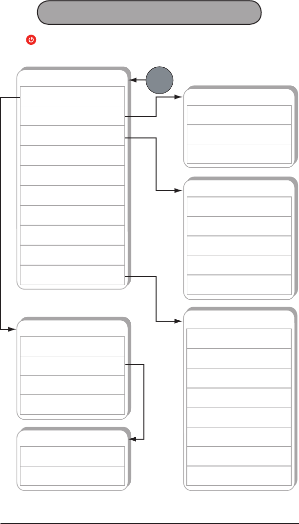
3 Expert Mode Menu
Press to power up the test set and then press MENU, refer to Figure
6 for the menu structure:
EXPERT MODE MENU
HPNA ANALYSIS
3.4
CABLE TESTING
3.3
POTS/DC/OHM
3.2
VDSL VTU-R
3.1
ETHERNET
3.7
SLM
3.6
WIRELESS (802.11)
3.5
PC ACCESS
3.8
MEASUREMENT SETUP
3.9
SYSTEM SETUP
3.10
POTS/DC/OHM
OHM
3.2.3
DC VOLTAGE
3.2.2
POTS
3.2.1
CABLE TESTING
WIREMAP
3.3.3
RJ LOSS
3.3.2
COAX LOSS
3.3.1
CABLE ID
3.3.4
TONE GENERATION
3.3.5
VDSL MAIN MENU
LINK MEASUREMENT
3.1.3
TONE TABLE
3.1.2
CURRENT STATUS
3.1.1
MODEM SETUP
3.1.4
TONE TABLE
SNR / TONE
3.1.2.2
BITS / TONE
3.1.2.1
MENU
SYSTEM SETUP
AUTO OFF
3.10.3
BACKLIGHT
3.10.2
CLOCK
3.10.1
PROFILE
3.10.6
VIEW STORE
3.10.7
SYSTEM INFORMATION
3.10.8
PROJECT
3.10.5
BATTERY
3.10.4
Figure 6 Expert Mode Menu Tree
16 SA976
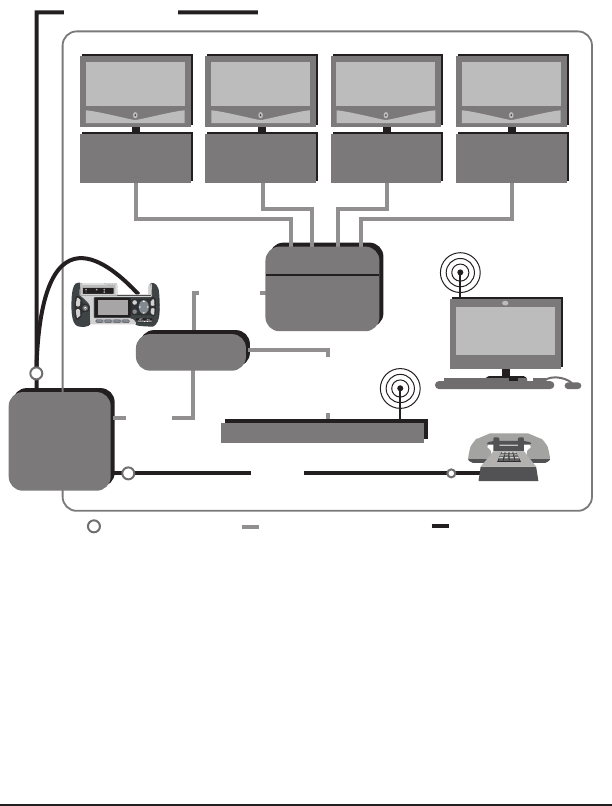
3.1 VDSL VTU-R
When the HTT is in this function, the SIGNAL LED indicates:
• Green: Link up
• Blinking Red: Attempting to open link and or training
• Red: Link down
NID
Set Top
Box
TV
PC
POTS
Diplexer
VDSL
Cable
NID
Splitter
Residence
Set Top
Box
TV
Set Top
Box
TV
Set Top
Box
TV
802.11
802.11
Test Point Coaxial Cable Twisted Pair
HPNA
HPNA
HPNA HPNA
VDSL + POTS
Residential Gateway
VDSL
+
HPNA
VDSL/POTS
DC/OHM
Port
Use the RJ-11-to-Clips (SA297) cable to connect to the test point.
Figure 7 VDSL Testing Connection Points
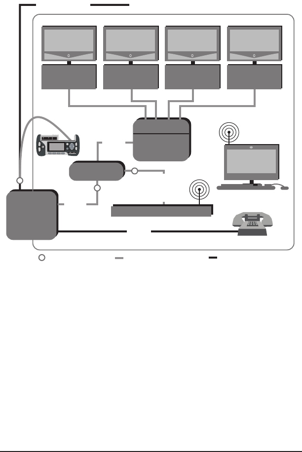
Figure 7 shows where to connect the HTT for VDSL testing and what
should be checked is:
• VDSL parameters outside the house before and after the balun at
the NID.
• VDSL parameters inside the house before RG installation.
• The following VDSL synch information:
- Downstream and Upstream rates (shown in the RATE eld,
Interleaved Speed)
- Downstream Max Rate, Capacity, SNR, and Delay
- Upstream Power and Delay

17HTT
The VDSL main menu screen contains:
• CURRENT STATUS
• TONE TABLE
• LINK MEASUREMENT
• MODEM SETUP
3.1.1 Current Status
CURRENT STATUS-DS
SHOWTIME
RATE 25024 KBPS
MAX 51240 KBPS
CPTY 48.88 %
CONT RETRN STORE
CURRENT STATUS-DS
SHOWTIME
SNRM 34.0 DB
ATTN 00.0 DB
DELAY 7.30 MS
CONT RETRN STORE
CURRENT STATUS-US
SHOWTIME
RATE 3004 KBPS
POWER 3.00 DBM
DELAY 7.30 MS
CONT RETRN STORE
Figure 8 Current Status Screens
These screens report:
Link status is shown above the box, SHOWTIME is shown in Figure
8, but this line can report:
LINK CLOSED: The HTT is idle and not trying to establish a link with
the DSLAM.
ATTEMPTING OPEN LINK: The HTT is attempting to establish a link
with the DSLAM.
TRAINING: The HTT has detected the DSLAM, and has begun the
VDSL training process.
SHOWTIME: The Link is up between the HTT and the DSLAM.
The following is reported inside the box:
DS: Downstream
RATE: This is the link up speed of the VDSL connection.
MAX: This is the maximum downstream rate the VDSL line can sup-
port.
CPTY: This is the downstream Capacity in percentage of utilization of
the VDSL connection (derived from the RATE/MAX speeds).
SNRM: Signal-to-Noise Ratio Margin is the downstream margin above
the noise oor where the signal and noise would be the same causing
the VDSL connection to drop.
ATTN: This is the aggregate downstream Attenuation of the signal
from the DSLAM to the HTT.
DELAY: This is the downstream Delay time from the DSLAM to the HTT.

18 SA976
US: Upstream
RATE: This is the Upstream link up speed.
POWER: This is the aggregate downstream Power of the signal from
the HTT to the DSLAM.
DELAY: This is the delay time from the HTT to the DSLAM.
These screens contain the following F-keys
CONT (F1): Press to return to the previous screen.
RETRN (F2): Press to retrain the modem and restart measurements.
STORE (F4): Press to store the measurements.
Interpreting the Results
Fixed Rate Circuits
Fixed rate circuits specify an exact data rate for the customer. If testing
a Fixed Rate service, look at the following:
Rate: Conrm that the value equals the xed rate set for the circuit,
in both the upstream and downstream directions. For example, if the
circuit under test is congured for 384 downstream/128 upstream, a
downstream rate at 384 and a upstream rate at 128 should be seen.
SNR Margin: Conrm that the signal-to-noise margin complies with
your company’s requirements. A common standard is 6 dB, higher
values can provide more room for any introduced noise.
Rate Adaptive Circuits
Rate adaptive circuits specify minimum and maximum data rates for a
circuit, and try to attain the maximum rate set by the DSLAM. If testing
a Rate Adaptive service, look at the following:
Rate: This value should be between the minimum and maximum
thresholds set for the circuit.
SNR Margin: The signal-to-noise margin value also needs to be above
the minimum allowable margin. Commonly it is 6 dB, your margin
might be higher. Since rate adaptive circuits try to use all the possible
bandwidth, the noise margin will typically be very close to 6 dB (or
the minimum value).
19HTT
3.1.2 Tone Table
This menu screen contains:
• BITS/TONE
• SNR/TONE
3.1.2.1 Bits/Tone
This feature measures the bits per tone distribution used by the modem
to transmit the provisioned rate. It displays the number of bits assigned
per tone as a graphic or as a table.
The rst screen allows selection of the following MHz ranges:
If Plan 997, use these: If Plan 998, use these:
SUMMARY: 0.138M–12.0M SUMMARY: 0.138M–12.0M
DS1: 0.138M–3.0M DS1: 0.138M–3.75M
USI: 3.0M–5.1M USI: 3.75M–5.2M
DS2: 5.1M–7.05M DS2: 5.2M–8.5M
US2: 7.05M–12.0M US2: 8.5M–12.0M
Note: US is upstream, DS is downstream frequencies.
After making a selection, press to view the BIT TABLE screen for
the selection made.
During modem initialization, a signal-to-noise measurement for each tone
is made. Bit distribution is then optimized to meet the desired bit rate.
Each tone can support a theoretical maximum of 15 bits. During operation,
the bit distribution may be adjusted to optimize bandwidth. The modem
constantly monitors the signal-to-noise ratio for each tone. If a tone de-
grades in quality, it sends a bit swap command to adjust the amount of
bits assigned to that particular tone. These bits may be added to a different
tone or taken out completely.
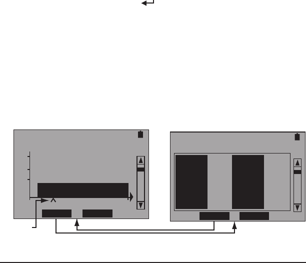
An example is shown in Figure 9:
Pointer
SUMMARY:0.138-12M
TONE 38 : 3 BITS
15
10
5
33 TABLE STORE 132
SUMMARY:0.138-12M
TONE# BIT TONE# BIT
33 3 37 3
34 3 38 3
35 3 39 3
36 3 40 3
GRPHC STORE
Figure 9 Bits/Tone Screens

20 SA976
A table of the tones is shown on the right of Figure 9. Listed for each
tone is the number of bits assigned to it. Press or Pg Up, Pg Dn
to scroll through all tones. Press F2 to view a graph of the tones shown
in the left screen in Figure 9.
In the Graph view, to learn the exact bit count of a specic tone, refer
to the line above the graph. This line provides the bit count for the tone
marked by the pointer arrow. In the left screen shown in Figure 9, the
pointer arrow is at tone 38 with 3 bits.
To move the pointer (^):
1. Press to move it one tone at a time.
2. Press Pg Up or Pg Dn to move to the next or previous screen in
the graphic sequence.
When nished viewing the graphic, press F2 to return to the table.
In either screen, press F3 to save the graph and table.
To view a narrower range of frequencies (less pages), press ESC and
select a range from the previously described list.
21HTT
3.1.2.2 SNR/Tone
This feature measures the signal-to-noise ratio for each downstream
tone used by the modem to transmit the provisioned rate. It displays
the SNR per tone as a graphic or as a table.
During modem initialization, a signal-to-noise measurement is made
for each tone; bit distribution is then optimized to meet the desired bit
rate. During operation, the bit distribution may be adjusted to optimize
bandwidth. The modem constantly monitors the signal-to-noise ratio
for each tone. If a tone degrades in quality, it sends a bit swap com-
mand to adjust the amount of bits assigned to that particular tone.
These bits may be added to a different tone or taken out completely.
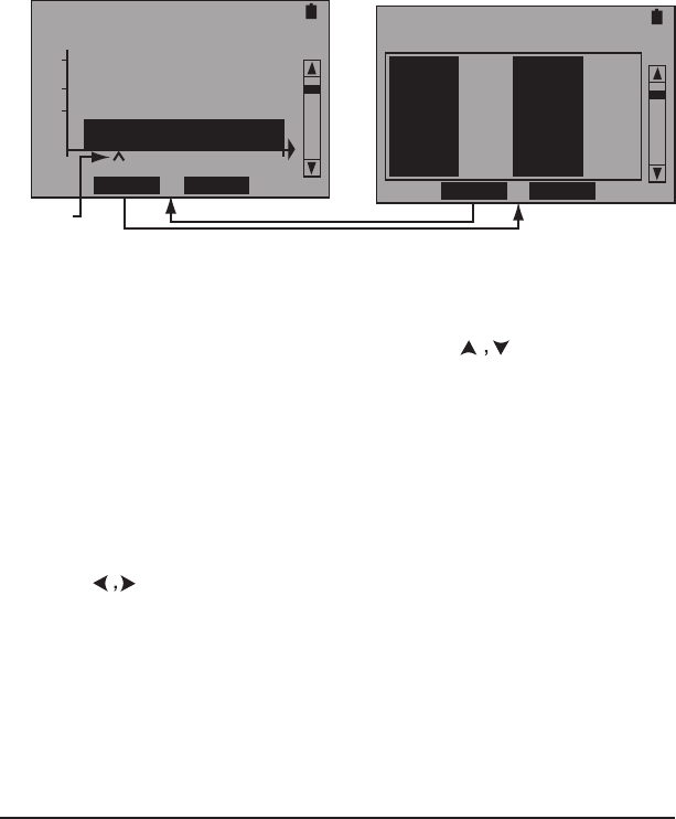
An example is shown in Figure 10:
Pointer
SNR / TONE
TONE 38 : 3 DB
15
10
5
33 TABLE STORE 132
SNR / TONE
TONE# DB TONE# DB
33 3 37 3
34 3 38 3
35 3 39 3
36 3 40 3
GRPHC STORE
Figure 10 SNR Per Tone Screens
A table of the tones is shown on the right of Figure 10. Listed for each
tone is the number of bits assigned to it. Press or Pg Up, Pg Dn
to scroll through all tones. Press F2 to view a graph of the tones shown
in the left screen in Figure 10.
In the Graph view, to learn the exact SNR for a specic tone, refer to
the line just above the graph. This line provides the SNR for the tone
marked by the pointer arrow. In the right screen shown in Figure 10,
the pointer arrow is at tone 38 with a 3 dB SNR.
To move the pointer (^):
1. Press to move it one tone at a time.
2. Press Pg Up or Pg Dn to move to the next or previous screen in
the graphic sequence.
When nished viewing the graphic, press F2 to return to the table.
In either screen, press F3 to save the graph and table.
22 SA976
3.1.3 Link Measurement
These screens provide information on errors and events.
LINK MEAS. - DS
SHOWTIME
CRC 0
FEC 0
HEC 0
NCD 0
STOP HIST STORE
LINK MEAS. - DS
SHOWTIME
OCD 0
LOS 0
SEF 0
STOP HIST STORE
LINK MEAS. - US
SHOWTIME
CRC 0
FEC 0
HEC 0
NCD 0
STOP HIST STORE
LINK MEAS. - US
SHOWTIME
OCD 0
LOS 0
SEF 0
STOP HIST STORE
LINK MEASUREMENT
SHOWTIME
ERR SEC 0
SEV ERR SEC 0
UNAVAIL SEC 0
BLK ERR RATE 0.0
STOP HIST STORE
LINK MEASUREMENT
SHOWTIME
SEF SEC 0
LOS SEC 0
RETRAINS 0
STOP HIST STORE
Figure 11 Link Measurements Screens
The rst four screens report the following for both DS (Downstream)
and US (Upstream):
CRC: Cyclic Redundancy Check anomaly indicates that in the
datastream, a received CRC-8 code is not identical to the locally cal-
culated CRC-8 code.
FEC: Forward Error Correction anomaly indicates that errors have been
corrected in the datastream.
HEC: Header Error Control anomaly indicates that an ATM cell with an
incorrect HEC is contained in the datastream.
NCD: No Cell Delineation anomaly occurs after ATM cell TC start-up when
ATM data is allocated to the buffer and as long as the cell delineation
process operating on this data is in the HUNT or PRESYNC state.

23HTT
OCD: Number of Out of Cell Delineation occurrences during the mea-
surement if it has been in synch, then goes out of synch.
LOS: Number of Loss Of Signal occurrences during measurement.
SEF: Number of Severe Error Frames occurrences during measure-
ment.
The last two screens report on the status of the received signal only.
Therefore, for VTU-R emulation, it shows results for the downstream
direction. The following results are shown:
ERR SEC: An Errored Second is dened as one second containing 1
or more CRC-8 anomalies or loss of signal.
SEV ERR SEC: A Severely Errored Second is dened as one second
containing 18 or more CRC-8 anomalies (a 30% errored block rate). A
severely errored second is also counted at loss of signal.
UNAVAIL SEC: An Unavailable Second begins after 10 consecutive
severely errored seconds.
BLK ERR RATE: The Block Error Rate during measurement.
SEF SEC: Total Severe Error Frame Seconds.
LOS SEC: Loss Of Signal Seconds.
RETRAINS: Number of resynchronizations (retrains) that have occurred
during measurement.
The following F-keys are available:
STOP/START (F1): Press to stop measurement, press again to start.
HIST (F2): Press History to reset all measurements to zero.
STORE (F4): Press to store the results.

24 SA976
3.1.4 Modem Setup
Note: As soon as this screen is accessed, if the link is up, the HTT
will close the link.
MODEM SETUP
LINK CLOSED
BAND PLAN: PLAN998
PLAN997
PLAN998
RETRN
Figure 12 Modem Setup Screen
This screen contains one item:
BAND PLAN
Options: PLAN997 or PLAN998
Press to select a BAND PLAN and press F1 to retrain and open
the link.
• PLAN997: Band Plan A, specied in Annex A of ITU-T G.993.1
standard.
•
PLAN998: Band Plan B, specied in Annex B of ITU-T G.993.1
standard.
25HTT
3.2 POTS/DC/OHM
This menu screen contains:
• POTS
• DC VOLTAGE
• OHM
Figure 13 shows where to connect the HTT for POTS/DC/OHM testing,
what should be checked is:
• Voltage is provided to the residence.
• Line is active and it can be used to dial out.
NID
Set Top
Box
TV
PC
POTS
Diplexer
VDSL
Cable
NID
Splitter
Residence
Set Top
Box
TV
Set Top
Box
TV
Set Top
Box
TV
802.11
802.11
HPNA
HPNA
HPNA HPNA
VDSL + POTS
Residential Gateway
VDSL
+
HPNA
VDSL/POTS
DC/OHM
Port
Test Point Coaxial Cable Twisted Pair
Use the RJ-11-to-Clips (SA297) cable to connect to the test point.
Figure 13 POTS/DC/OHM Testing Connection Points
26 SA976
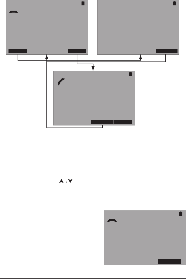
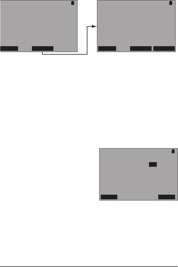
3.2.1 POTS
Use this function to dial out telephone numbers from a programed list.
In addition the HTT can accept or reject incoming calls. Before using
this feature, plug the supplied headset into the HEADSET port on the
HTT and use it to speak and listen during the call.
POTS/DC
DIAL: 18889229375
LIST OFFHK
POTS/DC
NUMBER SELECTION
> 3638000
18889229375
SELECT
POTS/DC
DIAL: 18889229375
ONHOOK DIAL
Figure 14 POTS Control and Phone List Screens
In the left screen shown in Figure 14, dial the displayed number by press-
ing F4 to go off hook and in the bottom screen press F4 to dial the number.
When nished, press F3 to go on hook and return to the left screen.
Change the number to dial by pressing F1 to display the right screen
in Figure 14. In it, use to select a number and press F4 to return
to the previous screen with new number displayed.
Note: Numbers can only be entered into the NUMBER SELECTION
screen using a PC.
POTS/DC
INCOMING CALL
DETECTED...
6/30/06 10:42 AM
MARTIN MULBURY
4083638002
ACCEPT
At any time while in the POTS
menu, a call can be received if not
engaged in a call. If a call is
received, the screen on the right is
displayed. In it, the date, time, and
caller ID info is displayed. Press F4
to accept the call. When finished,
press F3 to go on-hook.
Figure 15 Incoming Call Screen

27HTT
3.2.2 DC Voltage
The HTT can measure between 0 and +/- 200 DCV. To do so, connect
the HTT to the POTS circuit through it’s VDSL/POTS/DC/OHM RJ-11
port, select DC VOLTAGE, and the following screen is displayed:
Notes:
• If a voltage of more than 200 is
present, the HTT will display
“>200 VOLTS”.
• If a voltage of less than -200 is
present, the HTT will display
“< -200 VOLTS”.
POTS/DC
DC: -48 VOLTS
STORE
Figure 16 DC Voltage Screen
In the DC VOLTAGE screen, press F4 to store the measurement.
28 SA976
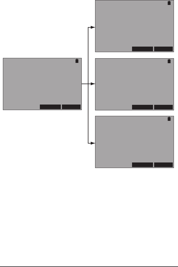
3.2.3 Ohm
The HTT can measure resistance on a POTS circuit. To do so, con-
nect the HTT to the POTS circuit through it’s VDSL/POTS/DC/OHM
port and select OHM and the measurement begins in the left screen
of Figure 17:
OHM
IN PROGRESS...
T-R:
T-G:
R-G:
RETEST STORE
OHM
DONE
T-R: 1000 K OHM
T-G: 1000 K OHM
R-G: 1000 K OHM
RETEST STORE
OHM
DONE
T-R: SHORT
T-G: SHORT
R-G: SHORT
RETEST STORE
OHM
DONE
T-R: OPEN
T-G: OPEN
R-G: OPEN
RETEST STORE
Figure 17 Ohm Screens
At any time, press F3 to retest. Press F4 to save the measurement. In the
right screens shown in Figure 17, the measured results are shown.
29HTT
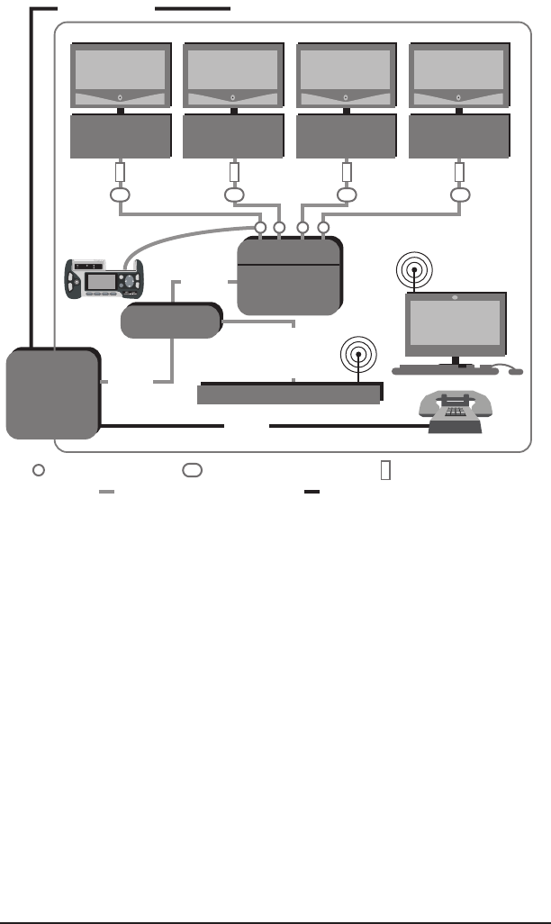
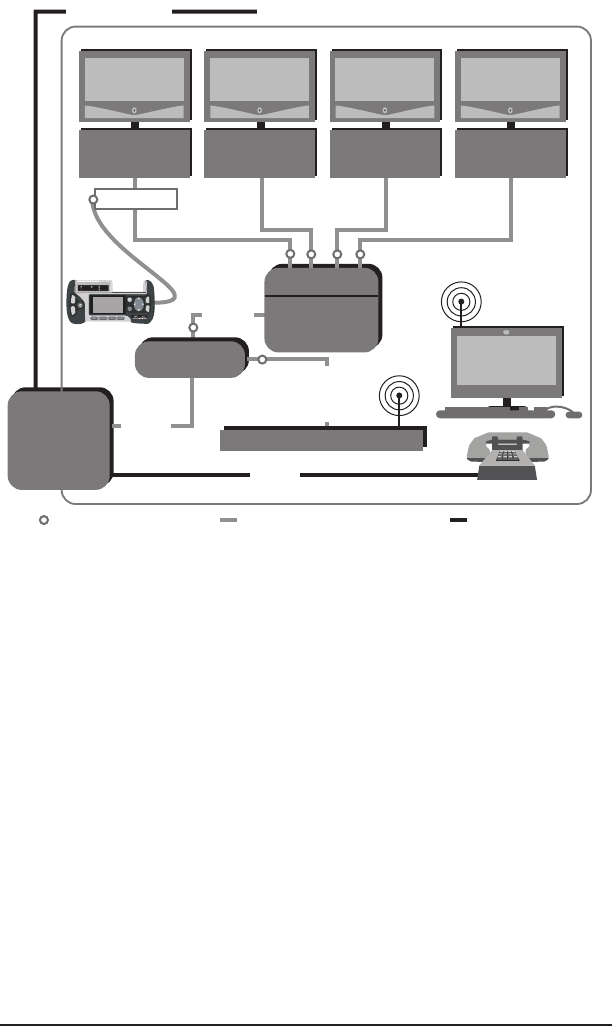
3.3 Cable Testing
NID
Set Top
Box
TV
PC
POTS
Diplexer
VDSL
Cable
NID
Splitter
Residence
Set Top
Box
TV
Set Top
Box
TV
Set Top
Box
TV
802.11
802.11
Wiremap ProbeTest Point
Coaxial Cable Twisted Pair
HPNA
HPNA
HPNA HPNA
VDSL + POTS
Residential Gateway
VDSL
+
HPNA
Cable ID Device
CABLE
TEST Port
Figure 18 Cable Testing Connection Points
Figure 18 shows where to connect the HTT for Cable testing. Use the
following tests to help identify cable faults inside the residence:
• Coax and RJ Loss: Provides cable loss measurement for coaxial
and twisted pair cable. Requires the Wiremap Probe.
• Wiremap: Verify that all 8 wires are properly connected in a Cat 5
cable. Requires the Wiremap Probe.
• Cable ID: Provides up to 5 different identications for cable runs
inside the residence. Requires up to ve Cable ID Devices.
• Diplexer test: Veriy frequency split by the diplexer. Requires the
Wiremap Probe.
• Tone Generation: Provides a tone used with a separate testing
device to detect a cable.
30 SA976
This menu screen contains:
• COAX LOSS
• RJ LOSS
• WIREMAP
• CABLE ID
• TONE GENERATION
These functions require the use of the Wiremap Probe shown in Figure
19:
• Coaxial Loss
• RJ Loss
• Wiremap
POWER
COAX RJ-45
WireMap Probe
Figure 19 Wiremap Probe
The Wiremap Probe generates frequencies used for measurements.

31HTT
3.3.1 Coaxial Cable Loss
This provides a coaxial cable loss measurement with the use of the
Wiremap Probe. To do so:
1. Perform the following calibration prior to testing:
A. Connect the SA318 test cable to the
HTT’s CABLE TEST port
and to the COAX port on Wiremap Probe.
B. Power ON the Wiremap Probe.
C.
Select from the EXPERT MODE MENU, CABLE TESTING >
COAX LOSS. When the screen gives a measurement for 7 and
14 MHz
, press F1 to calibrate the HTT to the Wiremap Probe
and test cable. This will zero out any losses from the test cable
and Wiremap Probe.
2. Connect the HTT using the calibrated SA318 test cable as shown in
Figure 18 to a desired test point.
3. Connect the calibrated HTT Wiremap Probe as shown in Figure 18
to a desired test point.
4. Select from the EXPERT MODE MENU, CABLE TESTING > COAX
LOSS and observe the results in the following screen:
CABLE TESTING
MODE: COAX LOSS
7MHz 14MHz
15.5 dB 10.0 dB
CALIB STORE
Figure 20 COAX Loss Screen
The following is reported:
• dB loss at 7 MHz (VDSL frequency range)
• dB loss at 14 MHz (HPNA frequency range)
5. If desired, repeat steps 2 through 4. Step 1 does not need to be
performed unless the HTT was powered down.
The screen contains the following F-keys:
CALIB (F1): Press to calibrate and zero out the Wiremap Probe and
the SA318 test cable.
STORE (F4): Press to store the information in the screen.

32 SA976
3.3.2 RJ Cable Loss
This provides an RJ cable loss measurement across any type of twisted
pair, whether CAT3 or CAT5 with the use of the Wiremap Probe. To
do so:
1. Perform the following calibration prior to testing:
A. Connect the SA318 test cable to the
HTT’s CABLE TEST port
and to the RJ-45 port on Wiremap Probe.
B. Power ON the Wiremap Probe.
C.
Select from the EXPERT MODE MENU, CABLE TESTING >
RJ LOSS. When the screen gives a measurement for 7 and 14
MHz
, press F1 to calibrate the HTT to the Wiremap Probe and
test cable. This will zero out any losses from the test cable and
Wiremap Probe.
2. Connect the HTT using the calibrated SA318 test cable as shown in
Figure 18 to a desired test point.
3. Connect the calibrated HTT Wiremap Probe as shown in Figure 18
to a desired test point.
4. Select from the EXPERT MODE MENU, CABLE TESTING > RJ LOSS
and observe the results in the following screen:
CABLE TESTING
MODE: RJ LOSS
7MHz 14MHz
15.5 dB 10.0 dB
EST LENGTH: 300 FT
CALIB STORE
Figure 21 RJ Loss Screen
The following is reported:
• dB loss at 7 MHz (VDSL frequency range)
• dB loss at 14 MHz (HPNA frequency range)
• EST LENGTH: Estimated cable length
5. If desired, repeat steps 2 through 4. Step 1 does not need to be
performed unless the HTT was powered down.
The screen contains the following F-keys:
CALIB (F1): Press to calibrate and zero out the Wiremap Probe and
the SA318 test cable.
STORE (F4): Press to store the information in the screen.

33HTT
3.3.3 Wiremap
This provides for CAT5 RJ-45 cable mapping, straight or crossover
with the use of the Wiremap Probe. To do so:
1. Connect one end of the CAT5 RJ-45 cable to the CABLE TEST RJ-
45 port on the HTT and the other end of the cable to the Wiremap
Probe’s RJ-45 port.
2. Select from the EXPERT MODE MENU, CABLE TESTING > WIRE-
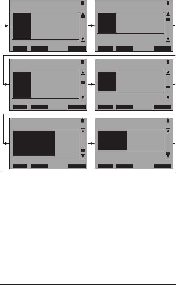
MAP and observe the results in the following screens:
Straight Cable
CABLE TESTING
MODE: WIREMAP
TESTSET -- PROBE
1--1 5--5
2--2 6--6
3--3 7--7
4--4 8--8
STORE
CABLE TESTING
MODE: WIREMAP
TESTSET -- PROBE
1--OPEN 5--5
2--OPEN 6--6
3--3 7--7
4--4 8--8
STORE
Straight Cable with Open
Figure 22 Wiremap Screens
The following can be displayed:
OPEN: Indicates a open conductor on the indicated conductor.
SHORT: Indicates a short between 2 or more indicated conductors.
The screen contains one F-key:
STORE (F4): Press to store the information in the screen.
34 SA976
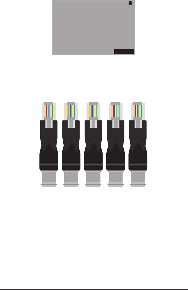
3.3.4 Cable ID
This identies up to ve lines using the plug-in Cable ID devices. If
the Cable ID device is detected, it’s matching number is displayed as
shown:
CABLE TESTING
MODE: CABLE ID
CABLE ID: 5
STORE
Figure 23 Cable ID Screen
Use this procedure:
1. Plug the Cable ID devices into the wall ports that need to be identi-
ed. Note that each device is numbered as shown in Figure 24.
1 2 3 4 5
Figure 24 Cable ID Devices
2. Connect the SA318 cable to the CABLE TEST RJ-45 port on the
HTT. Then connect the other end of the SA318 cable to the line to
be identied.
3. Select from the EXPERT MODE MENU, CABLE TESTING > CABLE
ID and observe the ID results.
The screen contains one F-key:
STORE (F4): Press to store the information in the screen.

35HTT
3.3.5 Tone Generation
Use this screen to generate a 570 Hz tone to detect cables with a
separate testing device.
TONE GENERATION
570 HZ TONE
TRANSMITTING...
STOP
Figure 25 Tone Generation Screen
In this screen, press F4 to stop transmitting the tone, press again to
start.
36 SA976
3.4 HPNA Analysis
NID
Set Top
Box
TV
PC
POTS
Diplexer
VDSL
Cable
NID
Splitter
Residence
Set Top
Box
TV
Set Top
Box
TV
Set Top
Box
TV
802.11
802.11
Test Point Coaxial Cable Twisted Pair
HPNA
HPNA
HPNA HPNA
VDSL + POTS
Residential Gateway
VDSL
+
HPNA
Splitter
HPNA
Port
Figure 26 HPNA Testing Connection Points
Connect the test set as an additional station by using an empty coaxial
drop or an added splitter. It provides results for:
• Station detection, veries that all stations are detected (up to 5 can
be present).
• HPNA Network Testing; Data Rate, Power, SNR, and Packet
Loss.
Connect to the network by:
• Standard Coax/RJ-11 patch cord.
• Either the HPNA Coax port or the HPNA RJ-11 port depending on
the type of cable on the HPNA network.
The rst step in HPNA testing is to setup the conguration screen
shown in Figure 27:

37HTT
HPNA CONFIG
INTERFACE COAX
MODE CLIENT
PACKET LENGT 1400
# OF PACKETS 5000
POWER YES
COAX RJ START
Figure 27 HPNA Conguration Screen
Congure the following:
INTERFACE
Options: COAX (F1), RJ (F2)
Select the interface to be tested.
MODE
Options: CLIENT (F1) HOST (F2)
Select the side to test.
PACKET LENGT
Displays the preset Packet Length, 1400
# OF PACKETS
Displays the preset Number Of Packets, 5000
POWER
Options: NO (F1), YES (F2)
Choose whether the received Power is measured.
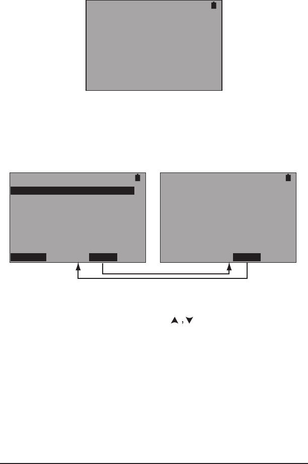
When nished, connect to the network and press F4 to start and the
HTT will download all working stations. The left screen shown in Figure
28 shows the active stations with their MAC addresses. Select a station
using and press to perform the test between the selected
station. An example is shown in the right screen of Figure 28:

38 SA976
2->3 HPNA ANALYSIS
RATE :112 MBPS
RX PWR :-58.70 DBM
SNR :38.32 DB
PACKET TX :5000
PACKET RX :5000
PACKET LOSS:0
CONFG TEST RESCAN MORE
RESET STORE MORE
HPNA ANALYSIS
TOTAL: 4 + TESTSET
MAC ID
1 00:D0:DD:22:01:34
X2 00:C5:D9:00:01:9A
X3 00:C5:D9:00:01:9B
X4 00:C5:D9:00:01:9C
CONFG TEST RESCAN MORE
RESET STORE MORE
Figure 28 HPNA Analysis Screens
The following is reported for each station:
RATE: Data rate between each HPNA device.
RX PWR: Received Power in DBM.
SNR: Signal-to-Noise in dB.
PACKET TX: Number of transmitted packets.
PACKET RX: Number of received packets.
PACKET LOSS: Number of lost packets.
The following F-keys are available:
CONFG (F1): Displays the Conguration Screen.
TEST (F2): Press to restart the test.
RESCAN (F3): Press to refresh the MAC address.
RESET (MORE, F1): Press to perform another HPNA network scan
(redownload HPNA software).
STORE (MORE, F2): Press to store the results.

39HTT
3.5 Wireless (802.11)
The HTT can detect and reveal information about wireless 802.11
networks. The HTT uses the SIGNAL LED to indicate the presence of
a network, green indicates a network, red indicates none are present.
The HTT must be in this menu in order to detect networks. The follow-
ing left screen is displayed after selecting this menu, the information
displayed is derived from any detected networks.
WIRELESS
APPLE NETWORK 9D8151
SRTI
RG1478
FREDS NETWORK
BOI NETWORK
COFFEE TRADER
RESCAN MAC
WIRELESS
00:11:24:9D:81:51
00:00:12:8C:74:42
01:54:24:1B:77:31
05:66:11:8F:97:99
21:57:18:5G:86:89
56:87:63:2E:32:66
RESCAN SSID
WIRELESS
SSID:
APPLE NETWORK 9D8151
RX POWER: -35 DBM
CH: 1 SECURE:YES
MAC ADDRESS:
00:11:24:9D:81:51
STORE
Press
Figure 29 Wireless Screens
In the left or middle screens of Figure 29, select an available network
using and press . The screen shown on the right of Figure 29
is then displayed with the following reported:
SSID: Network name, in this case APPLE NETWORK 9D8151.
RX POWER: Received power in dBm.
CH: Channel
SECURE: Either YES or NO, indicating if the network has security
codes.
MAC ADDRESS: In this case 00:11:24:9D:81:51.
This right screen in Figure 29 contains the following F-key:
STORE (F4): Press to store the information in the screen.
When nished, press ESC to return to the left or middle screen shown
in Figure 29. This screen contains the following F-keys:
RESCAN (F1): Press to rescan for wireless networks.
MAC/SSID (F2): Press to display in the AVAILABLE NETWORKS screen
either the SSID (common name) or MAC Address (number address
shown in the middle screen of Figure 29).
3.6 SLM
This feature will be available at a later date through a software up-
date.

40 SA976
3.7 Ethernet
This screen reports the status of the HTT ETHERNET port.
ETHERNET
LINK STATUS:LINK UP
SPEED :100 BASE
DUPLEX :FULL DUPLEX
DHCP STORE
Figure 30 Ethernet Screen
The following is reported:
LINK STATUS: LINK UP or LINK DOWN, if it is down the other items
in this screen are reported as N/A.
SPEED: 10 or 100 Mbps
DUPLEX: FULL of HALF
Note: Speed determination issues may result in connectivity issues,
see Table 1.
This screen contains the following F-keys:
DHCP (F1): Press to request an IP address.
STORE (F4): Press to store the information in the screen.
Congura-
tion Local
Device
Interface/
Mode
Congura-
tion Link
Partner
Interface/
Mode
Result-
ing Local
Device
Interface/
Mode
Resulting
Link Partner
Interface/
Mode
Comments
Auto
Negotiation
Auto
Negotiation
Maximum
common
capacity
Maximum
common
capacity
The module dis-
plays 100BaseT
full-duplex.
Auto
Negotiation
100 Mbps
full-duplex
100 Mbps
half-duplex
100 Mbps
full-duplex
Duplex
mismatch1
Auto
Negotiation
10 Mbps
full-duplex
10 Mbps
half-duplex
10 Mbps
full-duplex
Duplex
mismatch1
Note1
A duplex mismatch will result in performance issues, intermit-
tent connectivity, and possible loss of communication. When
troubleshooting local device issues, verify that the local
device and link partner are using a valid conguration.
Table 1 Ethernet Auto-Negotiation
41HTT
3.8 PC Access
Currently this menu screen contains BLUETOOTH. Use it along with the
PC Companion software to transfer stored results, update the HTT’s
software, or proles through a Bluetooth equipped PC.
Press F1 to turn the HTT Bluetooth on and see Figure 31:
BLUETOOTH NETWORK
LOCAL DEVICE
ADDR:08:00:17:20:74:86
NAME:HTT 000177
OFF SEARCH
BLUETOOTH NETWORK
REMOTE DEVICE (1/1)
ADDR:08:00:64:20:74:86
NAME:PC 001025
OFF SEARCH CONNEC
Figure 31 Bluetooth Network Screens
In the left screen shown in Figure 31, the HTT detects itself. Press F3
to detect other devices. If another device is detected SIGNAL stops
ashing and is green. Press F4 to connect to it. Once connected the
BLUETOOTH LED will be green.
Notes:
• If more than 1 remote device is found, press PgDn to select.
• The numbers (1/1) after REMOTE DEVICE indicate the rst device
is displayed out of 1 available device.
3.9 Measurement Setup
MEASUREMENT SETUP
THRESHOLD: ON
OFF ON
Use this screen to enable or disable
a preset threshold. The screen is
shown on the right:
Figure 32 Measurement Setup Screen
This screen contains:
THRESHOLD
Options: OFF (F1), ON (F4)
Choose whether or not to use the preset threshold. When on, the
PASS/FAIL LED is used to indicates the test result.
42 SA976
3.10 System Setup
This menu screen contains:
• CLOCK
• BACKLIGHT
• AUTO OFF
• BATTERY
• PROJECT
• PROFILE
• VIEW STORE
• SYSTEM INFORMATION
3.10.1 Clock
Use the screen in Figure 33 to set the Date and Time of day:
CLOCK
10:27:42
DATE(M/D/Y):07/06/2006
TIME(H:M:S):10:25:43
DEC INC SET
Figure 33 Clock Setup Screen
Set the following:
DATE
Use to select the Month/Date/Year and press F1 to decrease or
F2 to increase the selected eld.
TIME
Use to select the Hour/Minute/Second and press F1 to decrease
or F2 to increase the selected eld.
When nished, press F3 to set the clock.

43HTT
3.10.2 Backlight
Use the screen in Figure 34 to set the backlight on time and adjust
the screen contrast:
BACKLIGHT
BACKLIGHT: ON
[CONTRAST:USE ARROW KEYS]
OFF 1 MIN 5 MIN ON
Figure 34 Backlight Setup Screen
Set the following:
BACKLIGHT
Options: OFF (F1), 1 MIN (F2), 5 MIN (F3), ON (F4)
Choose the option that ts your needs.
CONTRAST
Use to adjust the screen contrast.
3.10.3 Auto Off
Use the screen shown in Figure 35 to control a shut off timer for the
HTT:
AUTO OFF
AUTO SHUT OFF: OFF
OFF 15 MIN 30 MIN
Figure 35 Auto Off Setup Screen
Set the following:
AUTO SHUT OFF
Options: OFF (F1), 15 MIN (F2), 30 MIN (F3)
Choose the option that ts your needs.
44 SA976
3.10.4 Battery
When this screen is accessed, the HTT calculates the percentage of
remaining battery life. As shown in Figure 36, the screen shows 84%,
but the on-screen battery indicator looks full. The on-screen indicator
has a resolution of 25% increments.
BATTERY
REMAINING: 84%
Figure 36 Battery Screen
3.10.5 Project
Use this screen to view preloaded assignments. The screens are shown
in Figure 37:
PROJECT
T001
T002
DELETE VIEW
CURRENT PROJECT
TICKET: T001
NAME : SUNRISE TELECOM
ADD. : 302 ENZO DR
SAN JOSE
PHONE : 3638000
LIST
Figure 37 Project Screens
In the screen shown on the left, press to select a project down-
loaded from a PC. Press F3 to view the details of a project as in the
right screen shown in Figure 37. The available detail elds are:
• TICKET number
• ADD. (address)
• PHONE number
Press F3 to return to the list. When a project is completed, select it
and press F1 to delete it.

45HTT
3.10.6 Prole
This feature will be available at a later date through a software up-
date.
3.10.7 View Store
Use this screen to conrm stored test results, use Pg Dn and Pg Up
to view the screens. Most test results are stored in CSV format and
will only be useful when they are downloaded to a PC and into a
spreadsheet.
3.10.8 System Information
This screen gives information on the software versions loaded into
the HTT and MAC address reserved for it. The screen is shown in
Figure 38:
SYSTEM INFORMATION
SW VERSION: T1.02
AT VERSION: 0A.01
XL VERSION: 04.05
MAC0:00:D0:DD:22:01:32
MAC1:00:D0:DD:22:01:33
MAC3:00:D0:DD:22:01:34
Figure 38 System Information Screen

46 SA976

47HTT
4 General Information
4.1 Customer Service
Sunrise Telecom Customer Service is available from 7:30 AM to 5:30
PM Pacic Standard Time (California, U.S.A.).
Customer Service performs the following functions:
• Answers customer questions over the phone on such topics as
product operation and repair.
• Facilitates prompt repair of malfunctioning test sets.
• Provides information about product upgrades.
A Return Merchandise Authorization (RMA) Number is required before
any product may be shipped to Sunrise Telecom for repair. Out-of-war-
ranty repairs require both an RMA and a Purchase Order before the
unit is returned. All repairs are warranted for 90 days.
Contact Customer Service if you need additional assistance at:
Customer Service
Sunrise Telecom Incorporated
302 Enzo Drive
San Jose, CA 95138
USA
Tel: 1-408-360-2200 or 1-800-701-5208
Fax: 1-408-363-8313
Internet: http://www.sunrisetelecom.com
e-mail: support@sunrisetelecom.com
4.2 Testing and Calibration Statement
Sunrise Telecom certies that this product was manufactured, tested,
and veried according to the applicable Sunrise Telecom Incorporated
manufacturing and test procedure(s). These formal procedures are de-
signed to assure that the product meets its required specications.
This product has no user-adjustable settings. During normal usage,
periodic calibration is not a requirement. However, if the product fails
during the self-verication test, during power up, the product can be
returned to the manufacturer for evaluation and repair.

48 SA976
4.3 Express Limited Warranty
A. Hardware Coverage. COMPANY warrants hardware products against
defects in materials and workmanship. During the warranty period
COMPANY will, at its sole option, either (i) refund of CUSTOMER’S
purchase price without interest, (ii) repair said products, or (iii) re-
place hardware products which prove to be defective; provided,
however, that such products which COMPANY elects to replace
must be returned to COMPANY by CUSTOMER, along with ac-
ceptable evidence of purchase, within twenty (20) days of request
by COMPANY, freight prepaid.
B. Software and Firmware Coverage. COMPANY warrants software
media and rmware materials against defects in materials and
workmanship. During the warranty period COMPANY will, at its sole
option, either (i) refund of CUSTOMER’S purchase price without
interest, (ii) repair said products, or (iii) replace software or rmware
products which prove to be defective; provided, however, that such
products which COMPANY elects to replace must be returned to
COMPANY by CUSTOMER, along with acceptable evidence of
purchase, within twenty (20) days of request by COMPANY, freight
prepaid. In addition, during the warranty period, COMPANY will
provide, without charge to CUSTOMER, all xes and patches to the
original product specications sold which COMPANY issues during
the warranty period. COMPANY does not warrant or represent that
all software defects will be corrected. In any case where COMPANY
has licensed a software product “AS-IS,” COMPANY’S obligation
will be limited to replacing an inaccurate copy of the original ma-
terial. This warranty does not cover upgrade or enhancements to
product software and rmware.
C.
Period. The warranty period for Hardware, Software and Firmware
will be Three (3) Years from date of shipment to CUSTOMER. The
COMPANY may also sell warranty extensions or provide a warranty
term of three years with the original sale, which provide a longer
coverage period for the test set chassis, software and rmware, in
which case the terms of the express limited warranty will apply to
said specied warranty term.
D. Only for CUSTOMER. COMPANY makes this warranty only for the
benet of CUSTOMER and not for the benet of any subsequent
purchaser or licensee of any merchandise.
E. LIMITATION ON WARRANTY. THIS CONSTITUTES THE SOLE AND
EXCLUSIVE WARRANTY MADE BY COMPANY WITH RESPECT
TO HARDWARE, SOFTWARE AND FIRMWARE. THERE ARE
NO OTHER WARRANTIES, EXPRESS OR IMPLIED. COMPANY
SPECIFICALLY DISCLAIMS THE IMPLIED WARRANTIES OF
MERCHANTABILITY AND FITNESS FOR A PARTICULAR PUR-

49HTT
POSE. COMPANY’S LIABILITY UNDER THIS AGREEMENT WITH
RESPECT TO A PRODUCT, INCLUDING COMPANY’S LIABILITY
FOR FAILURE AFTER REPEATED EFFORTS TO INSTALL EQUIP-
MENT IN GOOD WORKING ORDER OR TO REPAIR OR REPLACE
EQUIPMENT, SHALL IN NO EVENT EXCEED THE PURCHASE
PRICE OR LICENSE FEE FOR THAT PRODUCT, NOR SHALL
COMPANY IN ANY EVENT BE LIABLE FOR ANY INCIDENTAL,
CONSEQUENTIAL, INDIRECT, OR SPECIAL DAMAGES OF ANY
KIND OR NATURE WHATSOEVER, ARISING FROM OR RELATED
TO THE SALE OF THE MERCHANDISE HEREUNDER, INCLUDING
BUT NOT LIMITED TO DAMAGES ARISING FROM OR RELATED
TO LOSS OF BUSINESS, LOSS OF PROFIT, LOSS OF GOODWILL,
INJURY TO REPUTATION, OVERHEAD, DOWNTIME, REPAIR OR
REPLACEMENT, OR CHARGE-BACKS OR OTHER DEBITS FROM
CUSTOMER OR ANY CUSTOMER OF CUSTOMER.
F. No Guaranty, Nonapplication of Warranty. COMPANY does not
guaranty or warrant that the operation of hardware, software, or
rmware will be uninterrupted or error-free. Further, the warranty
shall not apply to defects resulting from:
(1) Improper or inadequate maintenance by CUSTOMER;
(2) CUSTOMER-supplied software or interfacing;
(3) Unauthorized modication or misuse;
(4) Operation outside of the environmental specications for the prod-
uct;
(5) Improper site preparation or maintenance; or
(6) Improper installation by CUSTOMER.

50 SA976

51HTT
Index
A
Auto Key; 13
Auto Off Setup Screen
AUTO SHUT OFF; 43
B
Backlight Setup Screen
BACKLIGHT; 43
CONTRAST; 43
Back Side
Battery Compartment; 9
Serial Number Label; 9
Battery Care and Storage; 10
Battery Replacement; 9
Battery Screen; 44
Bits/Tone Screens; 19
Bluetooth Network Screens; 41
Bottom Side Panel
DC power port; 9
C
Cable ID Devices; 34
Cable ID Screen; 34
Cable Testing Connection Points; 29
Calibration Statement; 47
Cautions; 10
Clock Setup Screen
DATE; 42
TIME; 42
COAX Loss Screen; 31
Current Status Screens
Downsteam
SNRM; 17
Downstream
ATTN; 17
CPTY; 17
DELAY; 17
MAX; 17
RATE; 17
Upstream
DELAY; 18
POWER; 18
RATE; 18

52 SA976
Customer Service; 47
D
DC Voltage Screen; 27
Display; 7
E
Ethernet Screen
DUPLEX; 40
LINK STATUS; 40
SPEED; 40
Expert Mode Menu Tree; 15
F
Figures
01 HTT Front View; 7
02 HTT Screen; 7
03 Main Port Panel; 8
04 Right Side Panel; 9
05 HTT Initial Startup Screen; 13
06 Expert Mode Menu Tree; 15
06 Upper Menu Screens; 15
07 VDSL Testing Connection Points; 16
08 Current Status Screens; 17
09 Bits Per Tone Screens; 19
10 SNR Per Tone Screens; 21
11 Link Measurements Screens; 22
12 Modem Setup Screen; 24
13 POTS/DC/OHM Testing Connection Points; 25
14 POTS Control and Phone List Screens; 26
15 Incoming Call Screen; 26
16 DC Voltage Screen; 27
17 Ohm Screens; 28
18 Cable Testing Connection Points; 29
19 Wiremap Probe; 30
20 COAX Loss Screen; 31
21 RJ Loss Screen; 32
22 Wiremap Screens; 33
23 Cable ID Screen; 34
24 Cable ID Devices; 34
25 Tone Generation Screen; 35
26 HPNA Testing Connection Points; 36
27 HPNA Conguration Screen; 37
28 HPNA Analysis Screens; 38
29 Wireless Screens; 39

53HTT
30 Ethernet Screen; 40
31 Bluetooth Network Screens; 41
32 Measurement Setup Screen; 41
33 Clock Setup Screen; 42
34 Backlight Setup Screen; 43
35 Auto Off Setup Screen; 43
36 Battery Screen; 44
37 Project Screens; 44
39 System Information Screen; 45
H
HPNA Analysis Screens
PACKET LOSS; 38
PACKET RX; 38
PACKET TX; 38
RATE; 38
RX PWR; 38
SNR; 38
HPNA Conguration Screen
# OF PACKETS; 37
INTERFACE
COAX or RJ; 37
MODE
CLIENT or HOST; 37
PACKET LENGTH; 37
POWER; 37
HPNA Testing Connection Points; 36
K
Keypad; 8
L
LEDs; 7
Link Measurements Screens
BLK ERR RATE; 23
CRC; 22
ERR SEC; 23
FEC; 22
HEC; 22
LOS; 23
LOS SEC; 23
NCD; 22
OCD; 23
RETRAINS; 23
SEF; 23

54 SA976
SEF SEC; 23
SEV ERR SEC; 23
UNAVAIL SEC; 23
Link status; 17
M
Measurement Setup Screen
THRESHOLD
ON or OFF; 41
Modem Setup Screen
BAND PLAN
PLAN997 or PLAN998; 24
O
Ohm Screens; 28
P
POTS/DC/OHM Testing Connection Points; 25
POTS Control and Phone List Screens; 26
POTS Incoming Call Screen; 26
Project Screens; 44
R
Right Side Panel
HEADSET; 9
HPNA; 9
RJ Loss Screen; 32
S
SLM; 39
SNR Per Tone Screens; 21
System Information Screen; 45
T
Tables
01 Ethernet Auto-Negotiation; 40
Tone Generation Screen; 35
Top Side Panel
CABLE TEST; 8
ETHERNET; 8
SLM; 8
VDSL/POTS/DC/OHM; 8
V
VDSL Testing Connection Points; 16
VDSL VTU-R; Current Status Screens
Interpreting the Results; 18

55HTT
View Store; 45
W
Warnings; 2, 10
Warranty; 48
Wireless Screens
CH; 39
MAC ADDRESS; 39
RX POWER; 39
SECURE; 39
SSID; 39
Wiremap Probe; 30
Wiremap Screens; 33

56 SA976