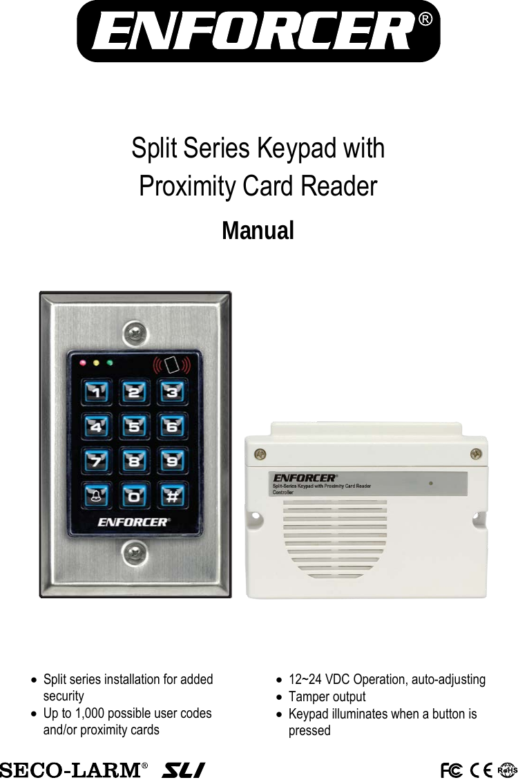
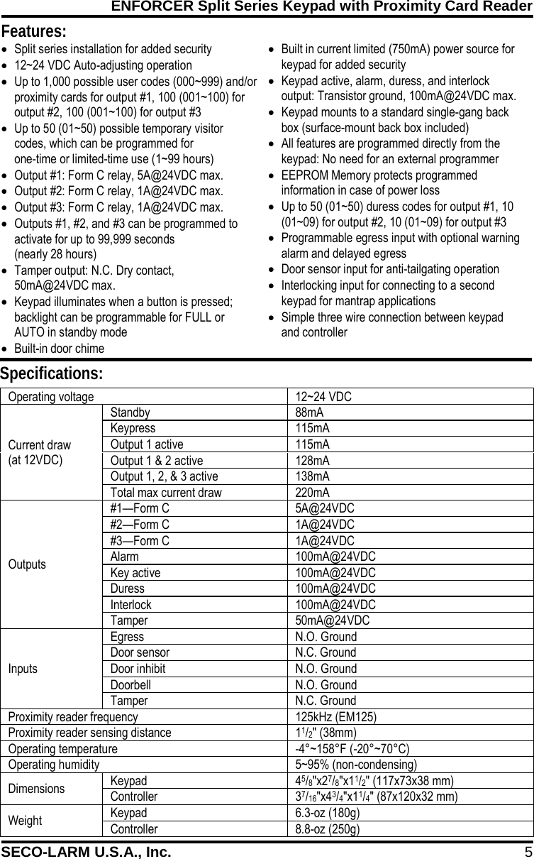
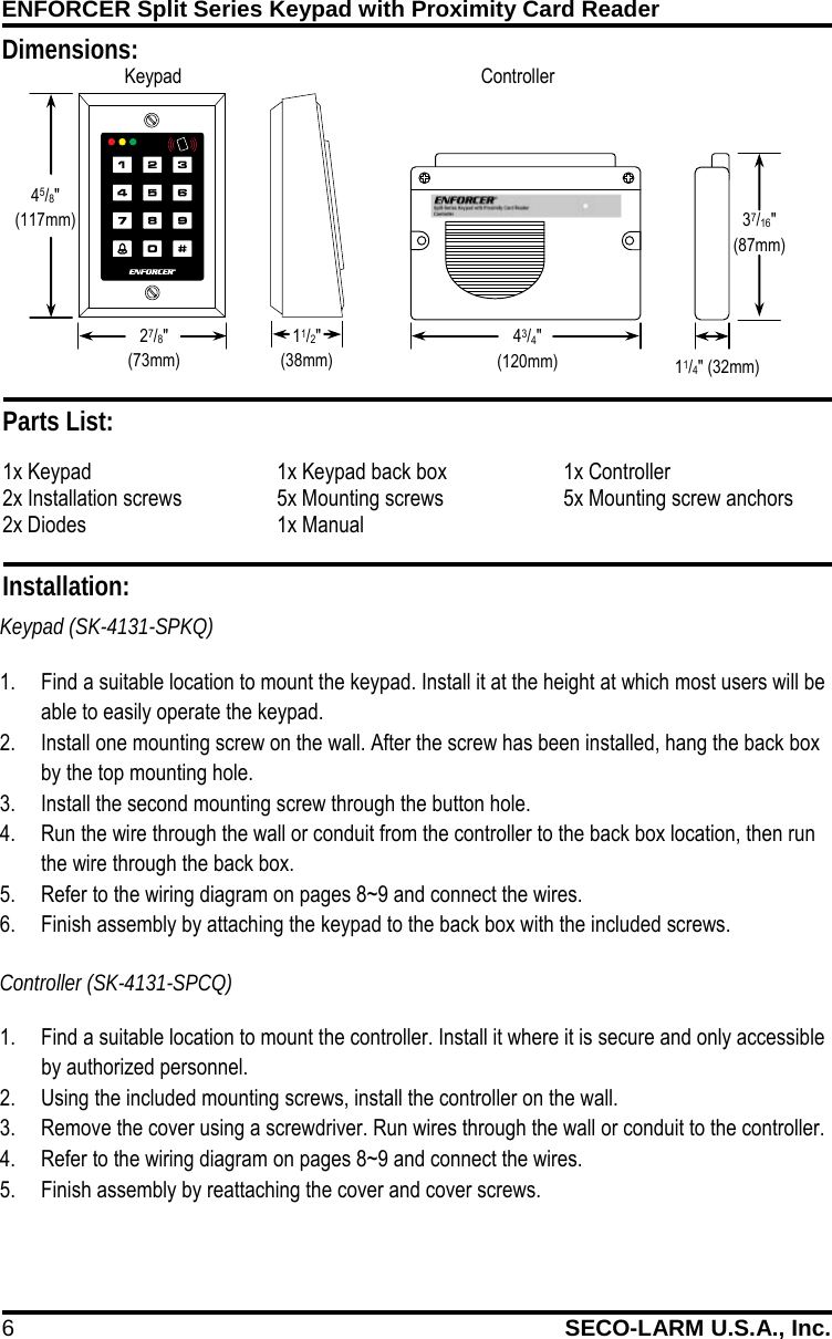
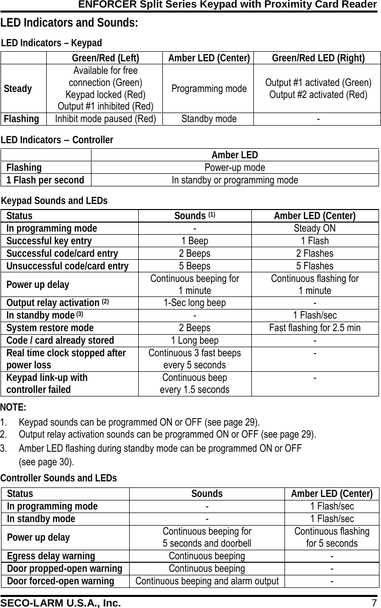
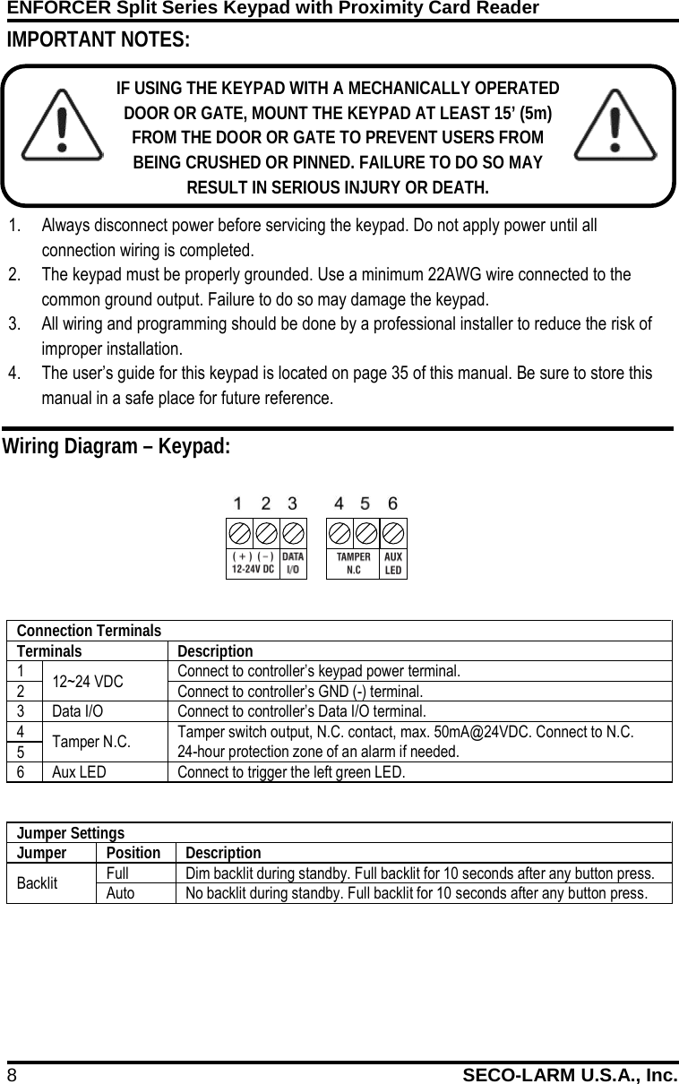
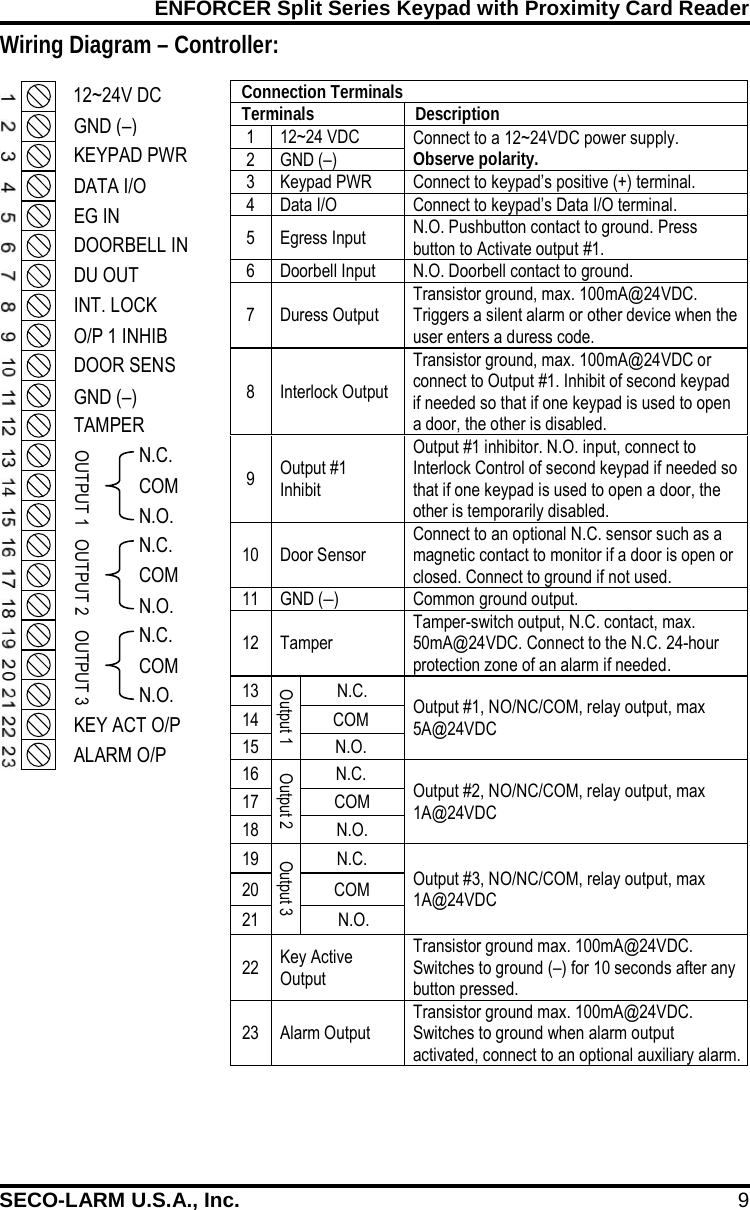
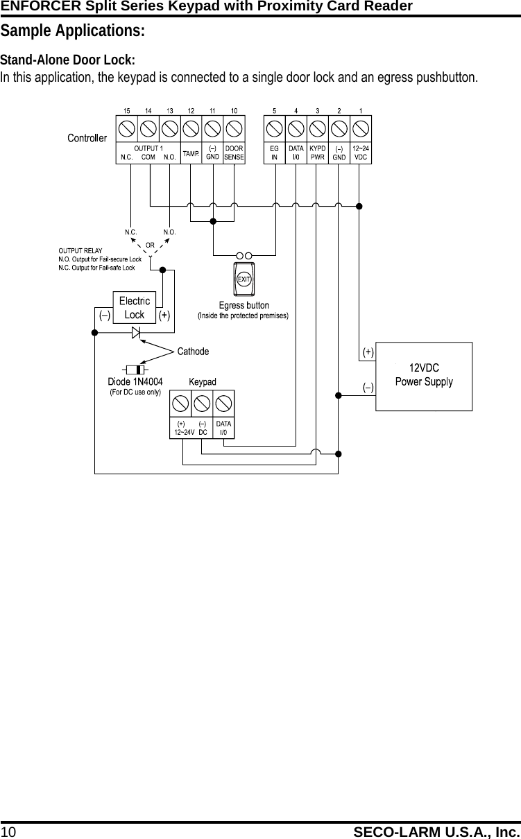
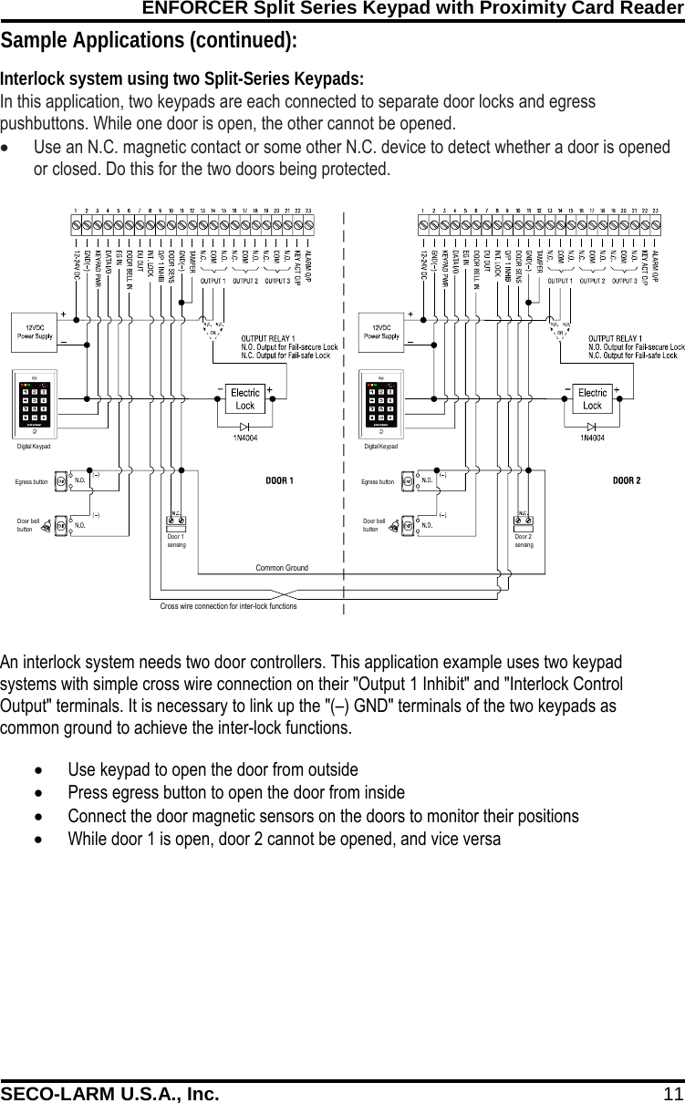
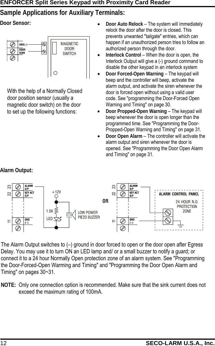
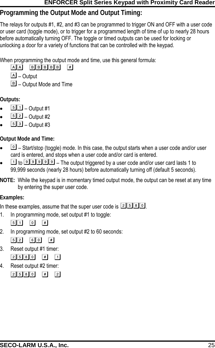
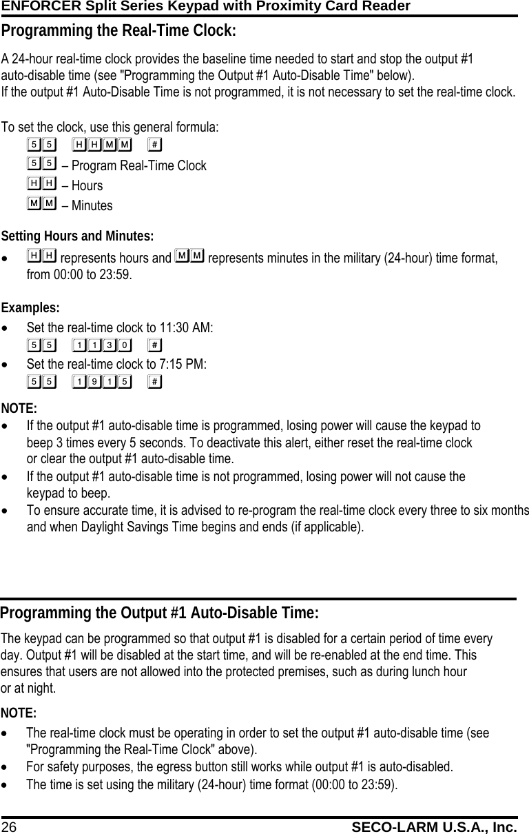
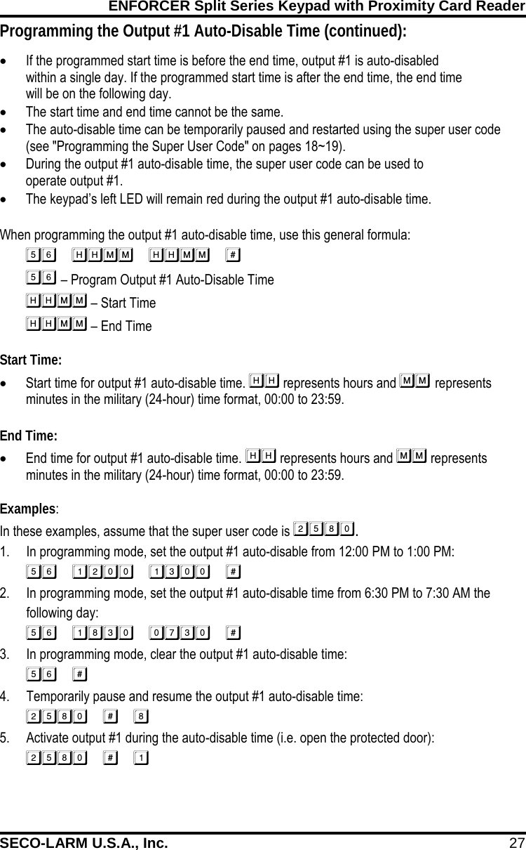
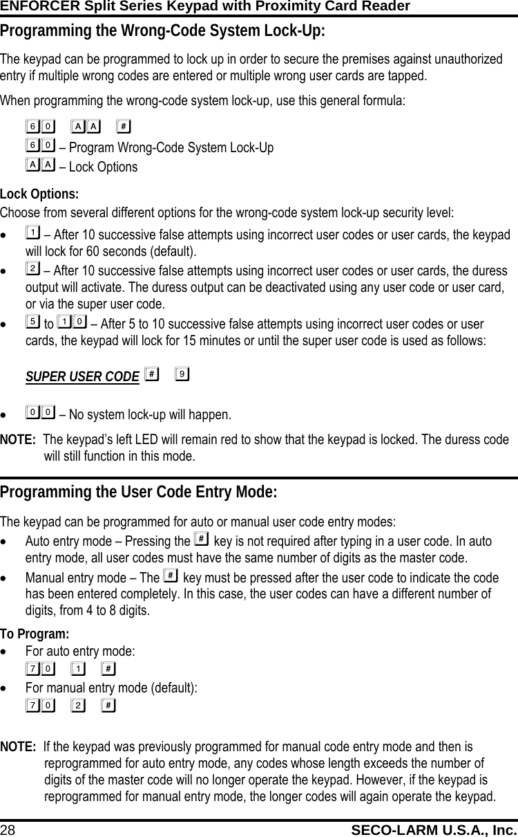
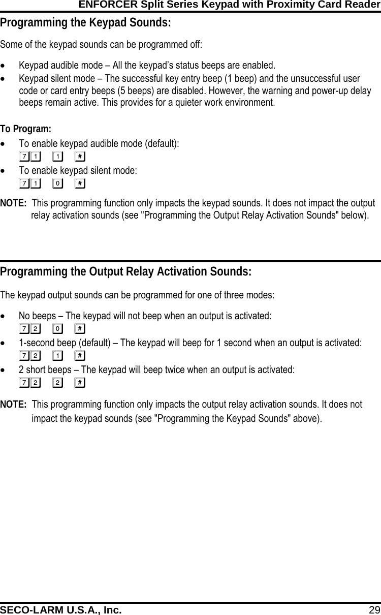
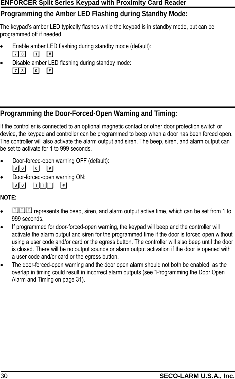
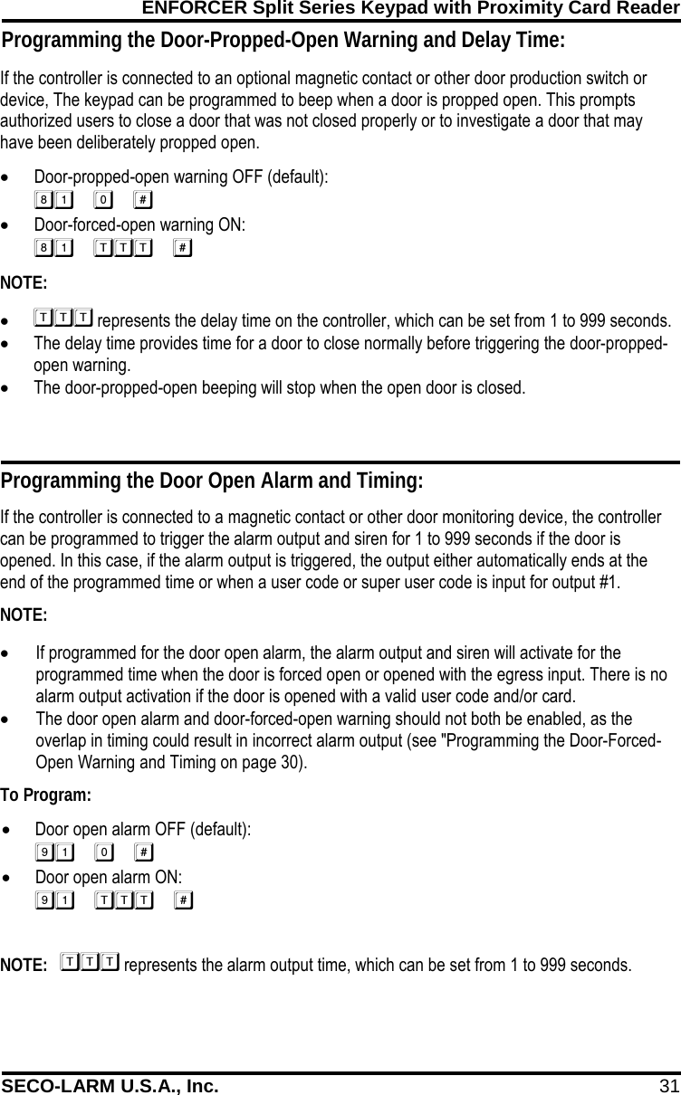
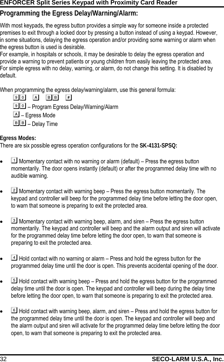
Superior Electronics 4131SPKQ SPLIT-SERIES KEYPAD User Manual

Superior Electronics Corporation SPLIT-SERIES KEYPAD

User Manual

       Split Series Keypad with  Proximity Card Reader Manual  • Split series installation for added security • Up to 1,000 possible user codes and/or proximity cards • 12~24 VDC Operation, auto-adjusting • Tamper output • Keypad illuminates when a button is pressed
ENFORCER Split Series Keypad with Proximity Card Reader 2 SECO-LARM U.S.A., Inc.                 Quick Installation Guide: This page is for installers looking to do a basic installation and programming of the keypad. For more in-depth installation and programming instructions, see the Table of Contents on page 4. Mounting Diagram: Quick Wiring Diagram: Keypad Controller Mounting screws Installation screws Mounting screws
ENFORCER Split Series Keypad with Proximity Card Reader SECO-LARM U.S.A., Inc. 3  Programming Instructions Follow the instructions bellow if the following covers your needs. • A new master code. • A single 4-digit user code for all users, and no proximity cards • One output to unlock a door. • A 3-second delay time in opening the door after the output is activated. This page is for installers looking to do a basic installation and programming of the keypad. For more in-depth installation and programming instructions, see the Table of Contents on page 4. Programming Tips • The master, super user, common user, visitor, duress, and user codes cannot be the same. • A flashing amber LED indicates the keypad is in standby mode. A solid amber LED indicates the keypad is in programming mode. • If the keypad is set for Auto Code Entry Mode, all codes will need to be the same number of digits as the master code (see page 28). 1. Power on the keypad and controller. 2. Turn off the beeping before the 1-minute power-up period ends:  3. Move the link-up jumper to the ON position. 4. Enter Programming Mode:         NOTE:   is the default master code. 5. Change the master code:   NOTE:   is the new master code. 6. Set the user code to operate output #1 (unlock the door):  NOTE:   chooses user ID #000 of 1,000 possible users (000~999).    is the new user code for user ID #000. 7. Set the output #1 delay time (skip this step if the default value of 5 seconds is acceptable):  NOTE:   sets the output #1 delay time for 3 seconds. 8. Exit Programming Mode:  9. Move the link-up jumper to the OFF position. NOTE:  The link-up procedure must be done during initial programming and any time  a. the master code is changed. Quick Programming Guide:
ENFORCER Split Series Keypad with Proximity Card Reader 4 SECO-LARM U.S.A., Inc.    Table of Contents: Quick Installation Guide  .................................................................................................................... 2 Mounting Diagram  ............................................................................................................................ 2 Quick Wiring Diagram  ....................................................................................................................... 2 Quick Programming Guide  ............................................................................................................... 3 Table of Contents  ............................................................................................................................. 4 Features  ........................................................................................................................................... 5 Specifications  ................................................................................................................................... 5 Dimensions  ....................................................................................................................................... 6 Parts List  ........................................................................................................................................... 6 Installation  ........................................................................................................................................ 6 LED Indicators and Sounds  .............................................................................................................. 7 Important Notes  ................................................................................................................................ 8 Wiring Diagram – Keypad  ................................................................................................................. 8 Wiring Diagram – Controller  ............................................................................................................. 9 Sample Applications  ................................................................................................................. 10~11 Sample Applications for Auxiliary Terminals  ............................................................................ 12~13 Getting Ready to Program  ........................................................................................................ 14~15 Programming Format and Default Programming Values  ................................................................ 16 System Restore  .............................................................................................................................. 17 Programming the Master Code  ...................................................................................................... 17 Programming the Super User Code  ......................................................................................... 18~19 Programming Common User Codes  ........................................................................................ 19~20 Programming User Codes and Proximity Cards  ....................................................................... 20~21 Programming Visitor Codes for Output #1  ...................................................................................... 22 Programming Duress Codes  .................................................................................................... 23~24 Programming the Output Mode and Output Timing  ........................................................................ 25 Programming the Real-Time Clock  ................................................................................................ 26 Programming the Output #1 Auto-Disable Time  ....................................................................... 26~27 Programming the Wrong-Code System Lock-Up  ........................................................................... 28 Programming the User Code Entry Mode  ...................................................................................... 28 Programming the Keypad Sounds  .................................................................................................. 29 Programming the Output Relay Activation Sounds  ........................................................................ 29 Programming the Amber LED Flashing during Standby Mode  ....................................................... 30 Programming the Door-Forced-Open Warning and Timing  ............................................................ 30 Programming the Door-Propped-Open Warning and Delay Time  .................................................. 31 Programming the Door Open Alarm and Timing  ............................................................................ 31 Programming the Egress Delay/Warning/Alarm  ....................................................................... 32~33 Direct Access to Programming (DAP)  ............................................................................................ 34 User’s Guide to Operating the SK-4131-SPSQ  .............................................................................. 35 Notes  .............................................................................................................................................. 36 Also Available  ................................................................................................................................. 36 Warranty  ......................................................................................................................................... 36
ENFORCER Split Series Keypad with Proximity Card Reader SECO-LARM U.S.A., Inc. 5    Features: Specifications: • Split series installation for added security • 12~24 VDC Auto-adjusting operation • Up to 1,000 possible user codes (000~999) and/or proximity cards for output #1, 100 (001~100) for output #2, 100 (001~100) for output #3 • Up to 50 (01~50) possible temporary visitor codes, which can be programmed for  one-time or limited-time use (1~99 hours) • Output #1: Form C relay, 5A@24VDC max. • Output #2: Form C relay, 1A@24VDC max. • Output #3: Form C relay, 1A@24VDC max. • Outputs #1, #2, and #3 can be programmed to activate for up to 99,999 seconds (nearly 28 hours) • Tamper output: N.C. Dry contact,    50mA@24VDC max. • Keypad illuminates when a button is pressed; backlight can be programmable for FULL or AUTO in standby mode • Built-in door chime • Built in current limited (750mA) power source for keypad for added security • Keypad active, alarm, duress, and interlock output: Transistor ground, 100mA@24VDC max. • Keypad mounts to a standard single-gang back box (surface-mount back box included) • All features are programmed directly from the keypad: No need for an external programmer • EEPROM Memory protects programmed information in case of power loss • Up to 50 (01~50) duress codes for output #1, 10 (01~09) for output #2, 10 (01~09) for output #3 • Programmable egress input with optional warning alarm and delayed egress • Door sensor input for anti-tailgating operation • Interlocking input for connecting to a second keypad for mantrap applications • Simple three wire connection between keypad  and controller  Operating voltage 12~24 VDC Current draw (at 12VDC) Standby 88mA Keypress 115mA Output 1 active 115mA Output 1 & 2 active 128mA Output 1, 2, & 3 active 138mA Total max current draw 220mA Outputs #1—Form C 5A@24VDC #2—Form C 1A@24VDC #3—Form C 1A@24VDC Alarm 100mA@24VDC Key active 100mA@24VDC Duress 100mA@24VDC Interlock 100mA@24VDC Tamper 50mA@24VDC Inputs Egress N.O. Ground Door sensor N.C. Ground Door inhibit N.O. Ground Doorbell N.O. Ground Tamper N.C. Ground Proximity reader frequency 125kHz (EM125) Proximity reader sensing distance 11/2" (38mm) Operating temperature -4°~158°F (-20°~70°C) Operating humidity 5~95% (non-condensing) Dimensions Keypad 45/8"x27/8"x11/2" (117x73x38 mm) Controller  37/16"x43/4"x11/4" (87x120x32 mm) Weight Keypad 6.3-oz (180g) Controller 8.8-oz (250g)
ENFORCER Split Series Keypad with Proximity Card Reader 6 SECO-LARM U.S.A., Inc.    Dimensions: 11/4" (32mm) 43/4" (120mm) Keypad  Controller  Installation: Keypad (SK-4131-SPKQ) 1. Find a suitable location to mount the keypad. Install it at the height at which most users will be able to easily operate the keypad. 2. Install one mounting screw on the wall. After the screw has been installed, hang the back box by the top mounting hole. 3. Install the second mounting screw through the button hole. 4. Run the wire through the wall or conduit from the controller to the back box location, then run the wire through the back box. 5. Refer to the wiring diagram on pages 8~9 and connect the wires.  6. Finish assembly by attaching the keypad to the back box with the included screws. Controller (SK-4131-SPCQ) 1. Find a suitable location to mount the controller. Install it where it is secure and only accessible by authorized personnel. 2. Using the included mounting screws, install the controller on the wall. 3. Remove the cover using a screwdriver. Run wires through the wall or conduit to the controller. 4. Refer to the wiring diagram on pages 8~9 and connect the wires. 5. Finish assembly by reattaching the cover and cover screws. Parts List: 1x Keypad 1x Keypad back box 1x Controller 2x Installation screws 5x Mounting screws 5x Mounting screw anchors 2x Diodes 1x Manual   37/16"  (87mm) 45/8" (117mm) 27/8" (73mm) 11/2" (38mm)
ENFORCER Split Series Keypad with Proximity Card Reader SECO-LARM U.S.A., Inc. 7     LED Indicators and Sounds: Controller Sounds and LEDs NOTE: 1. Keypad sounds can be programmed ON or OFF (see page 29). 2. Output relay activation sounds can be programmed ON or OFF (see page 29). 3. Amber LED flashing during standby mode can be programmed ON or OFF  (see page 30). Status Sounds Amber LED (Center) In programming mode - 1 Flash/sec In standby mode - 1 Flash/sec Power up delay Continuous beeping for  5 seconds and doorbell Continuous flashing for 5 seconds Egress delay warning Continuous beeping - Door propped-open warning Continuous beeping - Door forced-open warning Continuous beeping and alarm output -   Green/Red (Left) Amber LED (Center) Green/Red LED (Right) Steady Available for free  connection (Green) Keypad locked (Red) Output #1 inhibited (Red) Programming mode Output #1 activated (Green) Output #2 activated (Red) Flashing Inhibit mode paused (Red) Standby mode -  Keypad Sounds and LEDs LED Indicators – Keypad LED Indicators – Controller  Amber LED Flashing Power-up mode 1 Flash per second In standby or programming mode  Status Sounds (1) Amber LED (Center) In programming mode - Steady ON Successful key entry 1 Beep 1 Flash Successful code/card entry 2 Beeps 2 Flashes Unsuccessful code/card entry 5 Beeps 5 Flashes Power up delay Continuous beeping for  1 minute Continuous flashing for 1 minute Output relay activation (2) 1-Sec long beep - In standby mode (3) - 1 Flash/sec System restore mode 2 Beeps Fast flashing for 2.5 min Code / card already stored 1 Long beep - Real time clock stopped after power loss Continuous 3 fast beeps every 5 seconds - Keypad link-up with controller failed Continuous beep  every 1.5 seconds -
ENFORCER Split Series Keypad with Proximity Card Reader 8 SECO-LARM U.S.A., Inc.             IMPORTANT NOTES: IF USING THE KEYPAD WITH A MECHANICALLY OPERATED DOOR OR GATE, MOUNT THE KEYPAD AT LEAST 15’ (5m) FROM THE DOOR OR GATE TO PREVENT USERS FROM BEING CRUSHED OR PINNED. FAILURE TO DO SO MAY RESULT IN SERIOUS INJURY OR DEATH. 1. Always disconnect power before servicing the keypad. Do not apply power until all connection wiring is completed. 2. The keypad must be properly grounded. Use a minimum 22AWG wire connected to the common ground output. Failure to do so may damage the keypad. 3. All wiring and programming should be done by a professional installer to reduce the risk of improper installation. 4. The user’s guide for this keypad is located on page 35 of this manual. Be sure to store this manual in a safe place for future reference. Wiring Diagram – Keypad: Connection Terminals Terminals Description 1 12~24 VDC Connect to controller’s keypad power terminal.  2 Connect to controller’s GND (-) terminal. 3 Data I/O Connect to controller’s Data I/O terminal. 4 Tamper N.C. Tamper switch output, N.C. contact, max. 50mA@24VDC. Connect to N.C. 24-hour protection zone of an alarm if needed. 5 6 Aux LED Connect to trigger the left green LED.  Jumper Settings Jumper Position Description Backlit Full Dim backlit during standby. Full backlit for 10 seconds after any button press. Auto No backlit during standby. Full backlit for 10 seconds after any button press.
ENFORCER Split Series Keypad with Proximity Card Reader SECO-LARM U.S.A., Inc. 9    Wiring Diagram – Controller: Connection Terminals Terminals Description 1 12~24 VDC Connect to a 12~24VDC power supply. Observe polarity. 2 GND (–) 3 Keypad PWR Connect to keypad’s positive (+) terminal. 4 Data I/O Connect to keypad’s Data I/O terminal. 5  Egress Input N.O. Pushbutton contact to ground. Press button to Activate output #1. 6 Doorbell Input N.O. Doorbell contact to ground. 7  Duress Output Transistor ground, max. 100mA@24VDC. Triggers a silent alarm or other device when the user enters a duress code. 8  Interlock Output Transistor ground, max. 100mA@24VDC or connect to Output #1. Inhibit of second keypad if needed so that if one keypad is used to open a door, the other is disabled. 9  Output #1 Inhibit Output #1 inhibitor. N.O. input, connect to Interlock Control of second keypad if needed so that if one keypad is used to open a door, the other is temporarily disabled. 10 Door Sensor Connect to an optional N.C. sensor such as a magnetic contact to monitor if a door is open or closed. Connect to ground if not used. 11 GND (–) Common ground output. 12 Tamper Tamper-switch output, N.C. contact, max. 50mA@24VDC. Connect to the N.C. 24-hour protection zone of an alarm if needed. 13 Output 1 N.C. Output #1, NO/NC/COM, relay output, max 5A@24VDC 14 COM 15 N.O. 16 Output 2 N.C. Output #2, NO/NC/COM, relay output, max 1A@24VDC 17 COM 18 N.O. 19 Output 3 N.C. Output #3, NO/NC/COM, relay output, max 1A@24VDC 20 COM 21 N.O. 22 Key Active Output Transistor ground max. 100mA@24VDC. Switches to ground (–) for 10 seconds after any button pressed. 23 Alarm Output Transistor ground max. 100mA@24VDC. Switches to ground when alarm output activated, connect to an optional auxiliary alarm.  12~24V DC GND (–) KEYPAD PWR DATA I/O EG IN DOORBELL IN DU OUT INT. LOCK O/P 1 INHIB DOOR SENS TAMPER N.C. COM N.O. N.C. COM N.O. N.C. COM N.O. KEY ACT O/P ALARM O/P OUTPUT 3 OUTPUT 2 GND (–) OUTPUT 1
ENFORCER Split Series Keypad with Proximity Card Reader 10 SECO-LARM U.S.A., Inc.    Sample Applications: In this application, the keypad is connected to a single door lock and an egress pushbutton. Stand-Alone Door Lock:
ENFORCER Split Series Keypad with Proximity Card Reader SECO-LARM U.S.A., Inc. 11 Common GroundEgress buttonDoor bellbuttonEgress buttonDigital KeypadDigital KeypadDoor bellbuttonDoor 1sensingDoor 2sensingCross wire connection for inter-lock functions   Sample Applications (continued): In this application, two keypads are each connected to separate door locks and egress pushbuttons. While one door is open, the other cannot be opened.  • Use an N.C. magnetic contact or some other N.C. device to detect whether a door is opened or closed. Do this for the two doors being protected.   Interlock system using two Split-Series Keypads: An interlock system needs two door controllers. This application example uses two keypad systems with simple cross wire connection on their "Output 1 Inhibit" and "Interlock Control Output" terminals. It is necessary to link up the "(–) GND" terminals of the two keypads as common ground to achieve the inter-lock functions. • Use keypad to open the door from outside • Press egress button to open the door from inside • Connect the door magnetic sensors on the doors to monitor their positions • While door 1 is open, door 2 cannot be opened, and vice versa
ENFORCER Split Series Keypad with Proximity Card Reader 12 SECO-LARM U.S.A., Inc.    • Door Auto Relock – The system will immediately relock the door after the door is closed. This prevents unwanted "tailgate" entries, which can happen if an unauthorized person tries to follow an authorized person through the door. • Interlock Control – When the door is open, the Interlock Output will give a (-) ground command to disable the other keypad in an interlock system • Door Forced-Open Warning – The keypad will beep and the controller will beep, activate the alarm output, and activate the siren whenever the door is forced open without using a valid user code. See "programming the Door-Forced Open Warning and Timing" on page 30. • Door Propped-Open Warning – The keypad will beep whenever the door is open longer than the programmed time. See "Programming the Door-Propped-Open Warning and Timing" on page 31. • Door Open Alarm – The controller will activate the alarm output and siren whenever the door is opened. See "Programming the Door Open Alarm and Timing" on page 31. The Alarm Output switches to (–) ground in door forced to open or the door open after Egress Delay. You may use it to turn ON an LED lamp and/ or a small buzzer to notify a guard; or connect it to a 24 hour Normally Open protection zone of an alarm system. See "Programming the Door-Forced-Open Warming and Timing" and "Programming the Door Open Alarm and Timing" on pages 30~31.   NOTE:  Only one connection option is recommended. Make sure that the sink current does not exceed the maximum rating of 100mA. 2211 232211 23Sample Applications for Auxiliary Terminals:                                         With the help of a Normally Closed door position sensor (usually a magnetic door switch) on the door to set up the following functions: Door Sensor: Alarm Output:
ENFORCER Split Series Keypad with Proximity Card Reader SECO-LARM U.S.A., Inc. 13    The Duress Output switches to (–) ground when a duress code is entered. You may use it to turn ON an LED lamp and/ or a small buzzer to notify a guard; or connect it to a 24 hour Normally Open protection zone of an alarm system. NOTE: Only one connection option is recommended. Make sure that the sink current does not exceed the maximum rating of 100mA. The Key Active Output switches to (–) ground for 10 seconds whenever a key is touched. You may use it to turn ON an LED lamp and for a small buzzer to notify a guard, or to energize a relay to switch ON lights or trigger a CCTV Camera to start recording.  NOTE: • Make sure that the relay for switching ON lights has high enough isolation between high voltage and low voltage to prevent damage of the keypad. • Only one connection option is recommended. Make sure the sink current does not exceed the maximum rating of 100mA. • External power supply and isolation relay are strictly necessary in driving high power device, such as lights. Sample Applications for Auxiliary Terminals (continued):    Key Active Output: Duress Output:
ENFORCER Split Series Keypad with Proximity Card Reader 14 SECO-LARM U.S.A., Inc.     Power up the Keypad: When the keypad is first powered up, it will beep continuously for about 1 minute. During this power-up time, if needed, use Direct Access to Programming (DAP) to reset the master code  (see "Direct Access to Programming (DAP)" on page 34). 1. Turn off the beeping before the 1-minute powered-up period ends:  This will immediately stop the beeping. When this beeping has ended, the keypad is ready for normal operation or for programming. Getting Ready to Program: Code and/or Cards: The SK-4131-SPSQ can be set to be activated by users in one of three ways: 1. Keypad code only – There are five types of keypad codes: • Master code – Used only for entering programming mode; there can be only one master code per keypad. • Super user code – Can be used to activate outputs #1, #2, and #3, or to disable (inhibit) or enable the operation of output #1. • User codes – Unique codes for each user to activate outputs #1, #2, or #3. • Visitor codes – Temporary user codes that can be assigned to visitors or temporary workers to activate output #1; the visitor codes can be programmed for one-time use or to expire after a set number of hours has passed. • Duress codes – Assigned to specific users as a way to send a silent alert if forced to use the keypad under duress. 2. Proximity card only – Standard 125kHz (EM125) proximity cards can be used to activate output #1, output #2, or output #3. 3. Card + code – For enhanced security, the user can be required to also enter a code after tapping a proximity card. The code may be unique to each card or to a group of users, or a common code can be used with all cards. Security Levels: There are four possible security levels for the SK-4131-SPSQ: 1. Card only – The most basic, convenient level of security. Hold a previously-programmed proximity card over the keypad to activate outputs #1, #2, or #3 (see "Programming User Codes and Proximity Cards" on pages 20~21). 2. User code only – Type in a 4- to 8-digit user code to activate outputs #1, #2, or #3 (see pages 20~21). 3. Card + Common user code – All valid proximity cards can be programmed with a single common user code so that outputs #1, #2, or #3 can only be activated if one of the cards and the common user code are used together. The common user code is automatically assigned when each proximity card is programmed into the keypad (see "Programming Common User Codes" on pages 19~20). 4. Card + Unique user code – The most secure level. Each proximity card can be programmed with its own unique user code so that outputs #1, #2, or #3 can only be activated if the card and the unique code are used together (see pages 20~21).
ENFORCER Split Series Keypad with Proximity Card Reader SECO-LARM U.S.A., Inc. 15    Linking the Keypad and Controller: The keypad and controller must be linked prior to initial programming. 1. Enter the programming mode:   2. Move the link-up jumper on the controller to the ON position. 3. Exit programming mode:  4. Move the link-up jumper on the controller back to the OFF position. NOTE:  The link-up procedure must be done during initial programming and any time the  master code is changed.  Enter and Exit Programming Mode: All programming of the keypad is done in programming mode. 1. Enter the programming mode:   NOTE:   is the master code.  is the default master code (see "Programming the Master Code" on page 17 to program a new master code). The amber LED will turn to a steady ON to indicate that the keypad is in programming mode. 2. Exit programming mode:  The  entry can be used to exit programming mode at any time while programming. The keypad’s amber LED will return to flashing, indicating standby mode, upon exiting programming mode. NOTE:  DO NOT DISCONNECT THE KEYPAD FROM POWER WHILE IN PROGRAMMING MODE. Disconnecting the keypad while in programming mode could cause a keypad memory error. Getting Ready to Program (continued):
ENFORCER Split Series Keypad with Proximity Card Reader 16 SECO-LARM U.S.A., Inc.     Function Parameters Default functions and values Page # 01 Master code Default 0000, code length from 4~8 digits 17 02 Super user code No default, must be programmed 18~19 03 Common user code for output #1 No default, must be programmed 19~20 04 Common user code for output #2 No default, must be programmed 19~20 05 Common user code for output #3 No default, must be programmed 19~20 10 User codes/cards for output #1 No default, must be programmed 20~21 20 User codes/cards for output #2 No default, must be programmed 20~21 30 User codes/cards for output #3 No default, must be programmed 20~21 40 Visitor codes for output #1 No default, must be programmed 22 41 Duress codes for output #1 No default, must be programmed 23~24 42 Duress codes for output #2 No default, must be programmed 23~24 43 Duress codes for output #3 No default, must be programmed 23~24 51 Output mode for output #1 5-Second output, momentary 25 52 Output mode for output #2 5-Second output, momentary 25 53 Output mode for output #3 5-Second output, momentary 25 55 System real-time clock No default, must be programmed 26 56 Output #1 auto-disable time No default, must be programmed 26~27 60 Wrong-code system lock-up Locks keypad after 10 false code/card tries 28 70 User code entry mode Manual entry of "#" after each code 28 71 Keypad sounds Programming and operation beeps enabled 29 72 Output relay activation sounds 1-Second beep when output is activated 29 73 Amber LED standby flashing Amber LED flashes on standby 30 80 Door-forced-open warning Warning disabled 30 81 Door-propped-open warning Warning disabled 31 90 Egress delay/warning/alarm Egress output happens immediately 32~33 91 Door open alarm and timing Alarm output is disabled 31  NOTE:  The Direct Access to Programming (DAP) code 2828 (page 34) and the system restore code (page 17) are fixed and cannot be changed, even via programming.  Programming Format and Default Programming Values: In this manual, the format used for programming the keypad is as follows: • A 2 digit () FUNCTION identifier to tell the keypad what is being programmed. • A varying number of digits () to represent the parameters of this FUNCTION. • The () key to confirm programming of the FUNCTION. The following is a list of different programming functions:
ENFORCER Split Series Keypad with Proximity Card Reader SECO-LARM U.S.A., Inc. 17    System restore will reset all programming values except the master code back to the default values shown on page 16. 1. Make sure the keypad is in programming mode (see "Enter and Exit Programming Mode" on page 15). 2. Initiate system restore:  NOTE: • System restore will reset ALL programming except the master code back to default values. Be careful to use system restore only when absolutely necessary. • System restore may take several minutes. The amber LED will flash rapidly during this time. • Once system restore has been completed, the keypad will beep twice to show that all programming values have been reset to their default values and are ready to be  re-programmed. • At this point, the keypad is still in programming mode.  Programming the Master Code: The master code is used to enter programming mode. The master code does not serve as a user code for activating outputs #1, #2, or #3. 1. Make sure the keypad is in programming mode (see "Enter and Exit Programming Mode" on page 15). 2. Enter new master code:  NOTE: •  represents the new master code, which can be 4 to 8 digits long. • There can be only one master code for the keypad. • Programming a new master code will overwrite the previous master code. • If the master code is forgotten, use Direct Access to Programming (DAP) to reset the master code (see page 34). • The master, super user, common user, visitor, duress, and user codes cannot be the same. • If the keypad is set for Auto Code Entry Mode, user codes will need to be the same number of digits as the master code (see "Programming the User Code Entry Mode" on page 28). • It is recommended to re-link the keypad and controller immediately after changing the master code. If the link-up procedure is not performed after changing the master code then the keypad will beep once every second until the keypad and controller are re-linked (see "Linking the Keypad and Controller" on page 15). System Restore:
ENFORCER Split Series Keypad with Proximity Card Reader 18 SECO-LARM U.S.A., Inc. Programming the Super User Code: 1. Make sure the keypad is in programming mode (see "Enter and Exit Programming Mode" on page 15). 2. Enter the new super user code:   NOTE:   •  represents the new super user code, which can be 4 to 8 digits long. • There can be only one super user code for the keypad. • Programming a new super user code will overwrite the previous super user code. • The master, super user, common user, visitor, duress, and user codes cannot be the same. Deleting the Super User Code: This function is useful for protecting the premises in case the super user code is forgotten. To delete a super user code: 1. Make sure the keypad is in programming mode (see page 15). 2. Enter:  Using the Super User Code: In these examples, assume the super user code is . 1. Activate or deactivate output #1 (timed or toggle, depending on programming):  2. Activate or deactivate output #2 (timed or toggle, depending on programming):  3. Activate or deactivate output #3 (timed or toggle, depending on programming):  Programming the Super User Code: The super user code has multiple functions: • The super user code can activate or deactivate output #1, output #2, and             output #3 at any time. • The super user code can toggle operation of output #1 on or off.  • The super user code can pause or restart the timed output #1 auto-disable period.  • The super user code can enable or disable output #1.  • The super user code is exempt from any system inhibition or lockup functions. It is              valid at any time.
ENFORCER Split Series Keypad with Proximity Card Reader SECO-LARM U.S.A., Inc. 19 Programming the Super User Code (continued): 4. Toggle operation of output #1 ON or OFF.  NOTE:   • This function is used to leave output #1 active for extended periods of time. • Do not forget to deactivate this function after its use is no longer required. • It is recommended to only use this function with fail-safe locks. • All functions requiring use of the door sensor input are suspended while this function is in use.   5. Temporarily pause or restart the timed output #1 auto-disable period:  NOTE:   • This function is used to enable the operation of output #1 if it was disabled using the output #1 auto-disable function (see pages 26~27). • When the output #1 auto-disable function is inactive, the left red LED will flash steadily. This indicates that output #1 may now be used.  6. Disable or enable output #1 (toggle, regardless of programming):  NOTE:   • For more information on programming timed or toggle mode, see "Programming the Output Mode and Output Timing" on page 25. • The left LED will remain red while output #1 is disabled. • For safety reasons, the egress button works regardless of whether output #1 is enabled or disabled via the super user code. • The super user code continues to operate output #1 even while that output is disabled. Programming Common User Codes: This function allows a common user code to be automatically added to each proximity card as it is programmed. Every proximity card user also uses the same common user code to operate outputs #1, #2, or #3. This provides greater security than programming the keypad to operate with the card alone. It is also more convenient than assigning each user a unique user code, although unique user codes offer an even greater degree of security. 1. To program a common user code for output #1:  2. To program a common user code for output #2:  3. To program a common user code for output #3: 
ENFORCER Split Series Keypad with Proximity Card Reader 20 SECO-LARM U.S.A., Inc.    Programming Common User Codes (continued): NOTE:   •  represents the new common user code, which can be 4 to 8 digits long. • Programming a new common user code will overwrite the previous common user code. • A common user code is not necessary if unique user codes are assigned. • The master, super user, common user, visitor, duress, and user codes cannot be the same. Programming User Codes and Proximity Cards: When programming user codes and/or proximity cards, use this general formula:    – Output   – Security Level (or , to delete a user code or card)   – User ID   – User Code/Proximity Card  Outputs: •  – Output #1, up to 1,000 possible user codes and proximity cards. •  – Output #2, up to 100 possible user codes and proximity cards. •  – Output #3, up to 100 possible user codes and proximity cards.  Security Levels and Card/Code Deletion: There are four possible security levels for the SK-4131-SPSQ: •  – Card only – The most basic, convenient level of security. Just tap a                 previously-programmed proximity card over the keypad to activate outputs #1, #2, or #3.  NOTE:  The duress code feature cannot be used with the keypad programmed to the "card only" security mode. However, a duress code can be entered instead of a card.  •  – User code only – Type a 4 to 8-digit user code to activate outputs #1, #2, or #3. •  – Card + Unique user code – The most secure level. This code is programmed separately for each card and can be unique to the card, or the same code can be used for a group or department. The card and code must be used together to operate the output. •  – Card + Common user code – All valid proximity cards can be programmed with a single common user code so that outputs #1, #2, or #3 can only be activated if one of the cards and the common user code are used together. The common user code is automatically assigned as each proximity card is programmed into a keypad. •  – Delete a programmed proximity card or code. •  – Delete all programmed proximity cards or codes for the selected output.
ENFORCER Split Series Keypad with Proximity Card Reader SECO-LARM U.S.A., Inc. 21    Programming User Codes and Proximity Cards (continued): User IDs: •  to  – 1,000 unique user IDs for user codes and prox cards for output #1. •  to  – 100 unique user IDs for user codes and prox cards for output #2  or output #3.  User Codes: • A user code can be 4 to 8 digits long, and must have the same length as all other codes if the keypad is used in auto code entry mode (see page 28). • The master, super user, common user, visitor, duress, and user codes cannot be  the same. Examples: 1. Program only a proximity card for user ID #017 for output #1:  READ CARD   2. Program a user code for user ID #010 for output #1:  3. Delete a proximity card for output #1:  READ CARD   4. Delete code or proximity card for user ID #002 for output #1:  5. Delete all users for output #1:  6. Program a proximity card for user ID #001 for output #1 for use with a common user code:  READ CARD  NOTE:  A common user code must already be programmed to the output  (see pages 19~20). 7. Program a proximity card for user ID #023 for output #2 for use with unique user code:  READ CARD  
ENFORCER Split Series Keypad with Proximity Card Reader 22 SECO-LARM U.S.A., Inc.    When programming visitor codes, use this general formula:    – Visitor ID   – Valid Duration (hours)   – Visitor Code  Visitor IDs: •  to  – 50 unique visitor IDs for visitor codes for output #1. •  – Delete all currently programmed visitor codes.  Valid Duration: •  – Set a one-time code. This code can only be used once by a visitor, after which it is automatically deleted. •  to  – Set the duration the visitor code will be valid, from 1 to 99 hours.  Visitor Codes: • A visitor code can be 4 to 8 digits long, and must have the same length as all other codes if the keypad is used in auto code entry mode (see "Programming the User Code Entry Mode" on page 28). • All visitor codes are deleted if power is lost.  Examples: 1. Set the visitor ID #01 code to 1268, and make it a one-time code:  2. Set the visitor ID #02 code to 1378, and make it valid for three hours:  3. Delete the visitor ID #02 from memory:  4. Delete all currently programmed visitor codes:  Programming Visitor Codes for Output #1: Visitor codes are temporary codes that expire after use or after a specified amount of time has elapsed. While active, they operate output #1 as normal user codes. FIRE       NOTE:   • Visitor codes cannot be used to deactivate the duress output (see "Operating Duress Codes" on page 24).  • If the keypad is powered down, any programmed visitor codes will be deleted.
ENFORCER Split Series Keypad with Proximity Card Reader SECO-LARM U.S.A., Inc. 23    Programming Duress Codes: Duress codes allow users to trigger a silent alarm or alert if they are forced to allow access to a protected area. If a user uses a duress code instead of his or her normal user code, outputs #1, #2, or #3 will activate as normal, but the duress output will simultaneously activate to trigger a silent alarm or alert.  NOTE: • Duress codes are always valid and are not inhibited by any other operation of the keypad. • Duress codes cannot be the same as any other codes. • Duress codes can be used either as stand-alone codes or in conjunction with a user card, depending on how the user codes are programmed (see "Programming User Codes and Proximity Cards" on pages 20~21). • The duress code should be easy to remember. For instance, it can be the same as a user’s normal user code, but with a single digit changed, as by subtracting or adding 1 to the first or last digit of the code. For example, if the user code is 1369, a good duress code might be 2369.  When programming duress codes, use this general formula:        – Output          – Duress ID         – Duress Code  Outputs: •  – Output #1 •  – Output #2 •  – Output #3  Duress IDs: •  to  – Up to 50 duress codes can be programmed for output #1. •  to  – Up to 10 duress codes can be programmed for output #2 or output #3. •  – Delete all currently programmed duress codes for the selected output.  Duress Codes: • A duress code can be 4 to 8 digits long and must have the same length as all other codes if the keypad is used in auto code entry mode (see "Programming the User Code Entry Mode" on page 28).
ENFORCER Split Series Keypad with Proximity Card Reader 24 SECO-LARM U.S.A., Inc.    Programming Duress Codes (continued): Examples: 1. Set the duress ID #01 code for output #1 to 2369:  2. Set the duress ID #01 code for output #2 to 23980:  3. Delete the duress ID #011 code for output #1 from memory:  4. Delete all duress codes for output #1 from memory.  Operating Duress Codes: If a duress code is used in place of a normal user code, both the appropriate outputs #1, #2, or #3 and the duress output will be activated. However, a duress code cannot deactivate the duress output. Only a normal user code/card, super user code, or a master code can deactivate the duress output.  NOTE:  A duress code can also be used in conjunction with a user card to activate the duress output. However, a user card alone cannot activate the duress output.  Examples: In these examples, assume that  is an output #1 duress code and that  is a user code. 1. Activate the duress output and output #1 using the duress code:  NOTE:  Subsequently entering the duress code will activate output #1 again, but will not deactivate the duress output. 2. Deactivate the duress output using the user code:  3. Activate the duress output and activate output #1 using the duress code and a user card: READ CARD 
ENFORCER Split Series Keypad with Proximity Card Reader SECO-LARM U.S.A., Inc. 25    Programming the Output Mode and Output Timing: The relays for outputs #1, #2, and #3 can be programmed to trigger ON and OFF with a user code or user card (toggle mode), or to trigger for a programmed length of time of up to nearly 28 hours before automatically turning OFF. The toggle or timed outputs can be used for locking or unlocking a door for a variety of functions that can be controlled with the keypad.  When programming the output mode and time, use this general formula:    – Output   – Output Mode and Time  Outputs: •  – Output #1 •  – Output #2 •  – Output #3  Output Mode and Time: •  – Start/stop (toggle) mode. In this case, the output starts when a user code and/or user card is entered, and stops when a user code and/or card is entered. •  to  – The output triggered by a user code and/or user card lasts 1 to 99,999 seconds (nearly 28 hours) before automatically turning off (default 5 seconds).  NOTE:  While the keypad is in momentary timed output mode, the output can be reset at any time by entering the super user code.  Examples: In these examples, assume that the super user code is . 1. In programming mode, set output #1 to toggle:  2. In programming mode, set output #2 to 60 seconds:  3. Reset output #1 timer:  4. Reset output #2 timer: 
ENFORCER Split Series Keypad with Proximity Card Reader 26 SECO-LARM U.S.A., Inc.    A 24-hour real-time clock provides the baseline time needed to start and stop the output #1      auto-disable time (see "Programming the Output #1 Auto-Disable Time" below).  If the output #1 Auto-Disable Time is not programmed, it is not necessary to set the real-time clock.  To set the clock, use this general formula:              – Program Real-Time Clock        – Hours          – Minutes Setting Hours and Minutes: •  represents hours and  represents minutes in the military (24-hour) time format,    from 00:00 to 23:59.  Examples: • Set the real-time clock to 11:30 AM:  • Set the real-time clock to 7:15 PM:  NOTE:  • If the output #1 auto-disable time is programmed, losing power will cause the keypad to        beep 3 times every 5 seconds. To deactivate this alert, either reset the real-time clock                or clear the output #1 auto-disable time. • If the output #1 auto-disable time is not programmed, losing power will not cause the         keypad to beep. • To ensure accurate time, it is advised to re-program the real-time clock every three to six months and when Daylight Savings Time begins and ends (if applicable).  Programming the Output #1 Auto-Disable Time: The keypad can be programmed so that output #1 is disabled for a certain period of time every day. Output #1 will be disabled at the start time, and will be re-enabled at the end time. This ensures that users are not allowed into the protected premises, such as during lunch hour           or at night. NOTE:   • The real-time clock must be operating in order to set the output #1 auto-disable time (see "Programming the Real-Time Clock" above). • For safety purposes, the egress button still works while output #1 is auto-disabled. • The time is set using the military (24-hour) time format (00:00 to 23:59). Programming the Real-Time Clock:
ENFORCER Split Series Keypad with Proximity Card Reader SECO-LARM U.S.A., Inc. 27    Programming the Output #1 Auto-Disable Time (continued): • If the programmed start time is before the end time, output #1 is auto-disabled within a single day. If the programmed start time is after the end time, the end time will be on the following day. • The start time and end time cannot be the same. • The auto-disable time can be temporarily paused and restarted using the super user code (see "Programming the Super User Code" on pages 18~19). • During the output #1 auto-disable time, the super user code can be used to operate output #1. • The keypad’s left LED will remain red during the output #1 auto-disable time.  When programming the output #1 auto-disable time, use this general formula:  – Program Output #1 Auto-Disable Time       – Start Time        – End Time Start Time: • Start time for output #1 auto-disable time.  represents hours and  represents minutes in the military (24-hour) time format, 00:00 to 23:59.  End Time: • End time for output #1 auto-disable time.  represents hours and  represents minutes in the military (24-hour) time format, 00:00 to 23:59.  Examples: In these examples, assume that the super user code is . 1. In programming mode, set the output #1 auto-disable from 12:00 PM to 1:00 PM:  2. In programming mode, set the output #1 auto-disable time from 6:30 PM to 7:30 AM the following day:  3. In programming mode, clear the output #1 auto-disable time:  4. Temporarily pause and resume the output #1 auto-disable time:  5. Activate output #1 during the auto-disable time (i.e. open the protected door): 
ENFORCER Split Series Keypad with Proximity Card Reader 28 SECO-LARM U.S.A., Inc.    Programming the User Code Entry Mode: The keypad can be programmed for auto or manual user code entry modes: • Auto entry mode – Pressing the  key is not required after typing in a user code. In auto entry mode, all user codes must have the same number of digits as the master code. • Manual entry mode – The  key must be pressed after the user code to indicate the code has been entered completely. In this case, the user codes can have a different number of digits, from 4 to 8 digits. SILVER To Program: • For auto entry mode:  • For manual entry mode (default):  Programming the Wrong-Code System Lock-Up: The keypad can be programmed to lock up in order to secure the premises against unauthorized entry if multiple wrong codes are entered or multiple wrong user cards are tapped.  When programming the wrong-code system lock-up, use this general formula:    – Program Wrong-Code System Lock-Up   – Lock Options Lock Options: Choose from several different options for the wrong-code system lock-up security level: •  – After 10 successive false attempts using incorrect user codes or user cards, the keypad will lock for 60 seconds (default). •  – After 10 successive false attempts using incorrect user codes or user cards, the duress output will activate. The duress output can be deactivated using any user code or user card, or via the super user code. •  to  – After 5 to 10 successive false attempts using incorrect user codes or user cards, the keypad will lock for 15 minutes or until the super user code is used as follows:  SUPER USER CODE  •  – No system lock-up will happen. NOTE:  The keypad’s left LED will remain red to show that the keypad is locked. The duress code will still function in this mode. NOTE:  If the keypad was previously programmed for manual code entry mode and then is reprogrammed for auto entry mode, any codes whose length exceeds the number of digits of the master code will no longer operate the keypad. However, if the keypad is reprogrammed for manual entry mode, the longer codes will again operate the keypad.
ENFORCER Split Series Keypad with Proximity Card Reader SECO-LARM U.S.A., Inc. 29    Programming the Keypad Sounds: Some of the keypad sounds can be programmed off: • Keypad audible mode – All the keypad’s status beeps are enabled. • Keypad silent mode – The successful key entry beep (1 beep) and the unsuccessful user code or card entry beeps (5 beeps) are disabled. However, the warning and power-up delay beeps remain active. This provides for a quieter work environment.  To Program: • To enable keypad audible mode (default):  • To enable keypad silent mode:  NOTE:  This programming function only impacts the keypad sounds. It does not impact the output relay activation sounds (see "Programming the Output Relay Activation Sounds" below). Programming the Output Relay Activation Sounds: The keypad output sounds can be programmed for one of three modes: • No beeps – The keypad will not beep when an output is activated:  • 1-second beep (default) – The keypad will beep for 1 second when an output is activated:  • 2 short beeps – The keypad will beep twice when an output is activated:   Mercury NOTE:  This programming function only impacts the output relay activation sounds. It does not impact the keypad sounds (see "Programming the Keypad Sounds" above).
ENFORCER Split Series Keypad with Proximity Card Reader 30 SECO-LARM U.S.A., Inc.    The keypad’s amber LED typically flashes while the keypad is in standby mode, but can be programmed off if needed. • Enable amber LED flashing during standby mode (default):  • Disable amber LED flashing during standby mode:   Programming the Door-Forced-Open Warning and Timing: If the controller is connected to an optional magnetic contact or other door protection switch or device, the keypad and controller can be programmed to beep when a door has been forced open. The controller will also activate the alarm output and siren. The beep, siren, and alarm output can be set to activate for 1 to 999 seconds. • Door-forced-open warning OFF (default):  • Door-forced-open warning ON:  NOTE: •  represents the beep, siren, and alarm output active time, which can be set from 1 to 999 seconds. • If programmed for door-forced-open warning, the keypad will beep and the controller will activate the alarm output and siren for the programmed time if the door is forced open without using a user code and/or card or the egress button. The controller will also beep until the door is closed. There will be no output sounds or alarm output activation if the door is opened with a user code and/or card or the egress button. • The door-forced-open warning and the door open alarm should not both be enabled, as the overlap in timing could result in incorrect alarm outputs (see "Programming the Door Open Alarm and Timing on page 31). Programming the Amber LED Flashing during Standby Mode:
ENFORCER Split Series Keypad with Proximity Card Reader SECO-LARM U.S.A., Inc. 31    If the controller is connected to an optional magnetic contact or other door production switch or device, The keypad can be programmed to beep when a door is propped open. This prompts authorized users to close a door that was not closed properly or to investigate a door that may have been deliberately propped open. • Door-propped-open warning OFF (default):  • Door-forced-open warning ON:  NOTE: •  represents the delay time on the controller, which can be set from 1 to 999 seconds. • The delay time provides time for a door to close normally before triggering the door-propped-open warning. • The door-propped-open beeping will stop when the open door is closed. Programming the Door Open Alarm and Timing: If the controller is connected to a magnetic contact or other door monitoring device, the controller can be programmed to trigger the alarm output and siren for 1 to 999 seconds if the door is opened. In this case, if the alarm output is triggered, the output either automatically ends at the end of the programmed time or when a user code or super user code is input for output #1. NOTE: • If programmed for the door open alarm, the alarm output and siren will activate for the programmed time when the door is forced open or opened with the egress input. There is no alarm output activation if the door is opened with a valid user code and/or card. • The door open alarm and door-forced-open warning should not both be enabled, as the overlap in timing could result in incorrect alarm output (see "Programming the Door-Forced-Open Warning and Timing on page 30). To Program: • Door open alarm OFF (default):  • Door open alarm ON:   NOTE:    represents the alarm output time, which can be set from 1 to 999 seconds. Programming the Door-Propped-Open Warning and Delay Time:
ENFORCER Split Series Keypad with Proximity Card Reader 32 SECO-LARM U.S.A., Inc.    Programming the Egress Delay/Warning/Alarm: With most keypads, the egress button provides a simple way for someone inside a protected premises to exit through a locked door by pressing a button instead of using a keypad. However, in some situations, delaying the egress operation and/or providing some warning or alarm when the egress button is used is desirable. For example, in hospitals or schools, it may be desirable to delay the egress operation and provide a warning to prevent patients or young children from easily leaving the protected area. For simple egress with no delay, warning, or alarm, do not change this setting. It is disabled by default.  When programming the egress delay/warning/alarm, use this general formula:          – Program Egress Delay/Warning/Alarm                    – Egress Mode              – Delay Time  Egress Modes: There are six possible egress operation configurations for the SK-4131-SPSQ: •  Momentary contact with no warning or alarm (default) – Press the egress button momentarily. The door opens instantly (default) or after the programmed delay time with no audible warning.  •  Momentary contact with warning beep – Press the egress button momentarily. The keypad and controller will beep for the programmed delay time before letting the door open, to warn that someone is preparing to exit the protected area.  •  Momentary contact with warning beep, alarm, and siren – Press the egress button momentarily. The keypad and controller will beep and the alarm output and siren will activate for the programmed delay time before letting the door open, to warn that someone is preparing to exit the protected area.  •  Hold contact with no warning or alarm – Press and hold the egress button for the programmed delay time until the door is open. This prevents accidental opening of the door.  •  Hold contact with warning beep – Press and hold the egress button for the programmed delay time until the door is open. The keypad and controller will beep during the delay time before letting the door open, to warn that someone is preparing to exit the protected area.  •  Hold contact with warning beep, alarm, and siren – Press and hold the egress button for the programmed delay time until the door is open. The keypad and controller will beep and the alarm output and siren will activate for the programmed delay time before letting the door open, to warn that someone is preparing to exit the protected area.
ENFORCER Split Series Keypad with Proximity Card Reader SECO-LARM U.S.A., Inc. 33    Programming the Egress Delay/Warning/Alarm (continued): NOTE:  When the egress button is programmed to hold for a delay time before the door is released, it is important to put a sign near the egress button to notify users of the delay time.  Delay Time: •  – No delay time (default): Output #1 operates immediately when the egress button is pressed.  •  to  – Egress button delay time: The delay time can be set from 1 to 99 seconds. This tells the keypad how long to wait after the egress button is pressed before activate output #1. Examples: 1. Momentary mode – Press the egress button, and the keypad and controller will beep for 5 seconds before output #1 activates: 2. Hold the button to activate – Press and hold the egress button for 10 seconds, and the keypad and controller will beep for those 10 seconds before output #1 activates: 3. Return to default setting – Press the egress button to activate output #1 with no beeping or delay: NOTE:  For safety and to avoid confusion, when a delay or a press-and-hold delay is programmed, please post a notice near the egress button, such as "Press and hold the button for 5 seconds or until the door is unlocked."
ENFORCER Split Series Keypad with Proximity Card Reader 34 SECO-LARM U.S.A., Inc.    Direct Access to Programming (DAP): Direct Access to Programming (DAP) is used to enter programming mode if the master code is forgotten. DAP will not change the programming of the SK-4131-SPSQ in any way.  To Use DAP: 1. Disconnect the keypad’s power. 2. Wait one minute to ensure that the keypad’s power is fully discharged. 3. Reconnect the power. The keypad will beep repeatedly for one minute. 4. While the keypad is beeping, move the DAP jumper to the ON position then back to the OFF position once to stop the beeping. 5. Enter the DAP code:   6. The amber LED will turn ON, indicating that the keypad is ready for a new master code to be programmed.  NOTE: • See "Programming the Master Code" on page 17 for how to program a new master code. • Direct Access to Programming (DAP) will not reset the keypad’s programming. It will only enter programming mode in order to program a new master code.  • For complete system reset, see "System Restore" on page 17.
ENFORCER Split Series Keypad with Proximity Card Reader SECO-LARM U.S.A., Inc. 35    See "Programming the Master Code" and "Programming the Super User Code" on pages 17~19 for functions specific to those authorized to use those codes.  Opening the Door: In these examples, assume that the user code is , the common user code is , and a unique user code is . • Security Level 1 – Card only READ CARD 1 Long beep indicates that the door can be opened.  • Security Level 2 – Code only  * 1 Long beep indicates that the door can be opened.  • Security Level 3 – Card + Common user code READ CARD 2 Short beeps and a rapidly flashing amber LED indicates the card is accepted and the keypad is waiting for the Common user code.  *1 Long beep indicates that the door can be opened. • Security Level 4 – Card + Unique user code READ CARD 2 Short beeps and a rapidly flashing amber LED indicates the card is accepted and the keypad is waiting for the Unique user code.  *1 Long beep indicates that the door can be opened.  NOTE:  For more information on security levels, please see "Getting Ready to Program" on   page 14. * The  key is not needed if the keypad is programmed for auto entry mode. See page 28.  User’s Guide to Operating the SK-4131-SPSQ: Operating the Egress Button: Press the egress button from inside the protected premises to unlock the door and exit without using the keypad.  NOTE:  For more information or programming the Egress button, please see "Programming the Egress Delay/Warning/Alarm" on pages 32~33).
ENFORCER Split Series Keypad with Proximity Card Reader 36 SECO-LARM U.S.A., Inc.     NOTICE: The information and specifications printed in this manual are current at the time of publication. However, the SECO-LARM policy is one of continual development and improvement. For this reason, SECO-LARM reserves the right to change specifications without notice. SECO-LARM is also not responsible for misprints or typographical errors. Copyright © 2017 SECO-LARM U.S.A., Inc. All rights reserved. This material may not be reproduced or copied, in whole or in part, without the written permission of SECO-LARM.  LIMITED LIFETIME WARRANTY: This SE CO-LARM product i s w arranted against d efects in m aterial an d workmanship while used in normal service for the lifetime of the product. SECO-LARM’s obligation is limited to the repair or replacement of any defective part if the unit is returned, transportation prepaid, to SECO-LARM. This Warranty is vo id i f damage i s caused by  or at tributed t o a cts of  G od, physical or  el ectrical m isuse or a buse, neglect, r epair or al teration, improper or abnormal usage, or faulty installation, or if for any other reason SECO-LARM determines that such equipment is not o perating pr operly as  a r esult of  c auses ot her t han d efects i n m aterial a nd w orkmanship. The s ole obl igation of  SECO-LARM and the purchaser’s exclusive remedy, shall be l imited to the replacement or repair only, at SECO-LARM’s option. In no event shall SECO-LARM be liable for any special, collateral, incidental, or consequential personal or property damage of any kind to the purchaser or anyone else. This limited lifetime warranty is for products sold and installed in the United States and Canada. For all other countries, the warranty is 1 (one) year.  SECO-LARM® U.S.A., Inc. 16842 Millikan Avenue, Irvine, CA, 92606 Website: www.seco-larm.com  PIHAK1 Phone: (949) 261-2999  |  (800) 662-0800 Email: sales@seco-larm.com MI_SK-4131-SPSQ_161220.docx  FCC COMPLIANCE STATEMENT FCC ID: K4E4131SPKQ THIS DEVICE COMPLIES WITH PART 15 OF THE FCC RULES. OPERATION IS SUBJECT TO THE FOLLOWING TWO CONDITIONS: (1) THIS DEVICE MAY NOT CAUSE HARMFUL INTERFERENCE AND (2) THIS DEVICE MUST ACCEPT ANY INTERFERENCE RECEIVED, INCLUDING INTERFERENCE THAT MAY CAUSE UNDESIRED OPERATION. (2):The change or modifications not expressly approved by the party responsible for compliance could void the user’s authority to operate the equipment. IMPORTANT N OTE: T o comply w ith t he F CC RF exposure c ompliance requirements no change t o the antenna or t he device i s per mitted. A ny c hange t o t he ant enna or  t he dev ice c ould r esult i n t he d evice ex ceeding t he R F ex posure requirements and voice user’s authority.   Also Available: Proximity Cards (sold in packs of 10) PR-K1S1-A  Proximity Fobs (sold in packs of 10) PR-K1K1-AQ  Notes:
37 SECO-LARM U.S.A., Inc. NOTE: This equipment has been tested and found to comply with the limitsfor a Class B digital, pursuant to Part 15 or the FCC Rules. These limits are designed to provide reasonable protection against harmful interference in a residential installation. This equipment generates, uses and can radiate radio frequency energy and, if not installed and used in accordance with the instructions, may casue harmful interference to radio communications, However, there is no guarantee that interference will not occur in a particular installation. If the equipment does cause harmful interference to radio or television reception, which can be determined by turning the equipment off and on, the user is encouraged to try to correct the interference by one or more of the following measures:--- Reorient or relocate the receiving antenna.--- Increase the separation between the equipment and receiver.--- Connect the equipment into an outlet on a circuit different from that to which the receiver is connected.--- Consult the dealer or an experienced radio/ TV technician for help.

Navigation menu