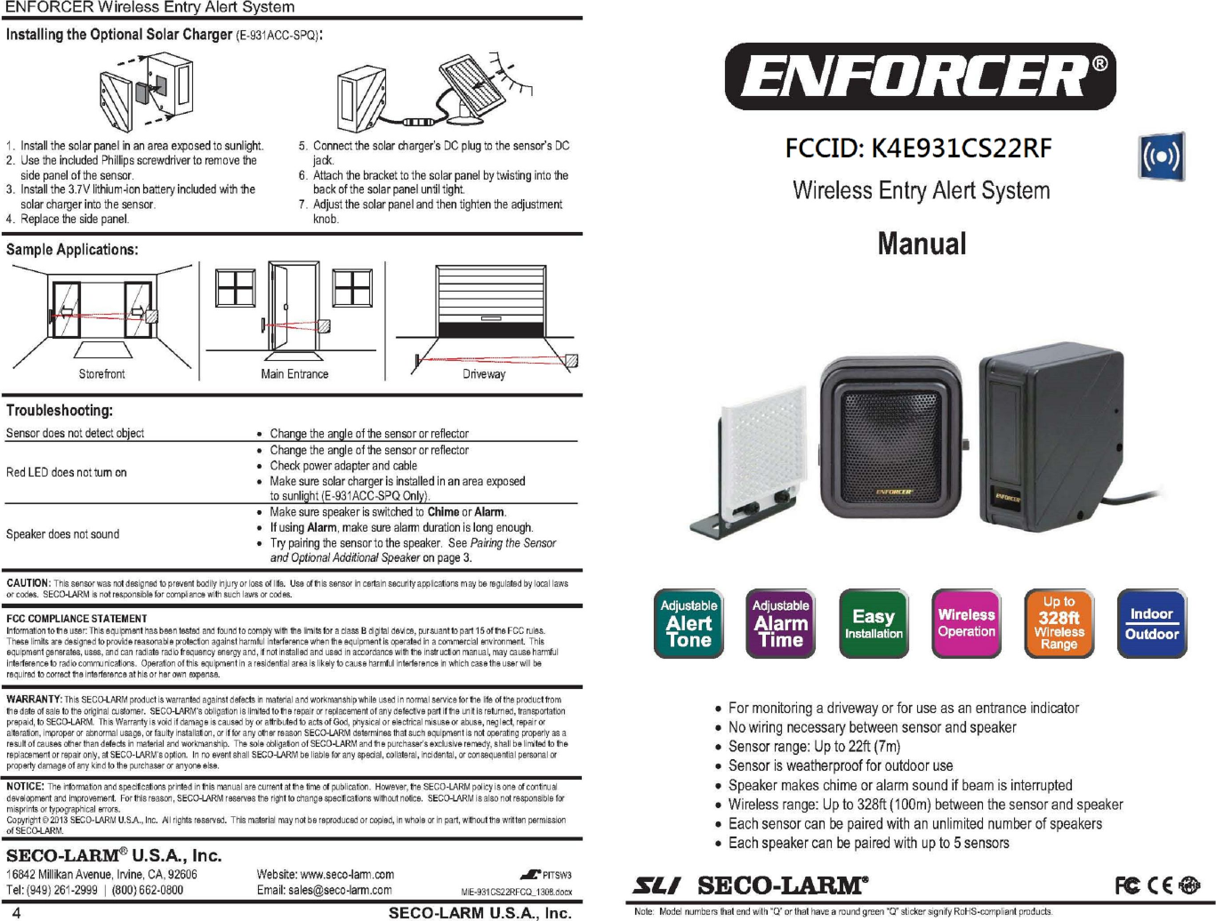
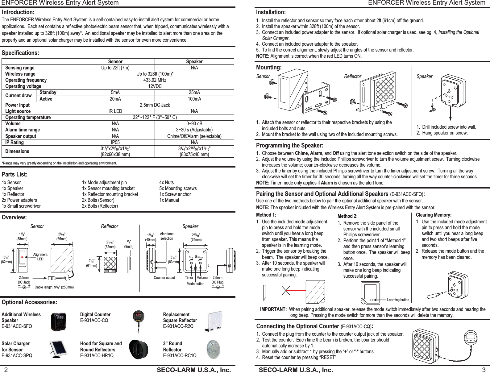
Superior Electronics 931CS22RF Wireless Door Entry Alarm & Counting System (Infrared Beam)/Solar Panel Included User Manual

Superior Electronics Corporation Wireless Door Entry Alarm & Counting System (Infrared Beam)/Solar Panel Included

User Manual

ENFORCER Wireless Entry Alert System SECO-LARM U.S.A., Inc.  3    Installation: 1. Install the reflector and sensor so they face each other about 2ft (61cm) off the ground. 2. Install the speaker within 328ft (100m) of the sensor. 3. Connect an included power adapter to the sensor.  If optional solar charger is used, see pg. 4, Installing the Optional Solar Charger. 4. Connect an included power adapter to the speaker. 5. To find the correct alignment, slowly adjust the angles of the sensor and reflector. NOTE: Alignment is correct when the red LED turns ON. Mounting: Programming the Speaker: Sensor Reflector Speaker 1. Drill included screw into wall. 2. Hang speaker on screw. 1. Attach the sensor or reflector to their respective brackets by using the included bolts and nuts. 2. Mount the bracket to the wall using two of the included mounting screws. 1. Choose between Chime, Alarm, and Off using the alert tone selection switch on the side of the speaker. 2. Adjust the volume by using the included Phillips screwdriver to turn the volume adjustment screw.  Turning clockwise increases the volume; counter-clockwise decreases the volume. 3. Adjust the timer by using the included Phillips screwdriver to turn the timer adjustment screw.  Turning all the way clockwise will set the timer for 30 seconds; turning all the way counter-clockwise will set the timer for three seconds. NOTE: Timer mode only applies if Alarm is chosen as the alert tone. Pairing the Sensor and Optional Additional Speakers (E-931ACC-SFQ): Use one of the two methods below to pair the optional additional speaker with the sensor. Method 1: 1. Use the included mode adjustment pin to press and hold the mode switch until you hear a long beep from speaker. This means the speaker is in the learning mode. 2. Trigger the sensor by breaking the beam.  The speaker will beep once. 3. After 10 seconds, the speaker will make one long beep indicating successful pairing. Method 2: 1. Remove the side panel of the sensor with the included small Phillips screwdriver. 2. Perform the point 1 of “Method 1” and then press sensor’s learning button once.  The speaker will beep once. 3. After 10 seconds, the speaker will make one long beep indicating successful pairing. Clearing Memory: 1. Use the included mode adjustment pin to press and hold the mode switch until you hear a long beep and two short beeps after five seconds. 2. Release the mode button and the memory has been cleared. Connecting the Optional Counter (E-931ACC-CQ): 1. Connect the plug from the counter to the counter output jack of the speaker. 2. Test the counter.  Each time the beam is broken, the counter should automatically increase by 1. 3. Manually add or subtract 1 by pressing the “+” or “-“ buttons 4. Reset the counter by pressing “RESET”. Learning button NOTE: The speaker included with the Wireless Entry Alert System is pre-paired with the sensor.  IMPORTANT:  When pairing additional speaker, release the mode switch immediately after two seconds and hearing the                          long beep. Pressing the mode switch for more than five seconds will delete the memory. ENFORCER Wireless Entry Alert System 2  SECO-LARM U.S.A., Inc.                  Introduction: The ENFORCER Wireless Entry Alert System is a self-contained easy-to-install alert system for commercial or home applications.  Each set contains a reflective photoelectric beam sensor that, when tripped, communicates wirelessly with a speaker installed up to 328ft (100m) away*.  An additional speaker may be installed to alert more than one area on the property and an optional solar charger may be installed with the sensor for even more convenience. Specifications:  Sensor Speaker Sensing range Up to 22ft (7m)  N/A Wireless range Up to 328ft (100m)* Operating frequency 433.92 MHz Operating voltage 12VDC Current draw Standby 5mA 25mA Active 20mA 100mA Power input 2.5mm DC Jack Light source IR LED N/A Operating temperature 32°~122° F (0°~50° C) Volume N/A 0~90 dB Alarm time range N/A 3~30 s (Adjustable) Speaker output N/A Chime/Off/Alarm (selectable) IP Rating IP55 N/A Dimensions 31/4”x29/16”x11/2”  (82x66x38 mm) 31/4”x215/16”x19/16” (83x75x40 mm)  Parts List: Overview: Optional Accessories: Additional Wireless  Speaker E-931ACC-SFQ Digital Counter E-931ACC-CQ  Replacement   Square Reflector E-931ACC-R2Q Solar Charger  for Sensor E-931ACC-SPQ Hood for Square and Round Reflectors E-931ACC-HR1Q 3” Round  Reflector E-931ACC-RC1Q Sensor Reflector Speaker 21/16” (52mm) 23/8” (61mm) 3/8” (9mm) *Range may vary greatly depending on the installation and operating environment. 19/16” (40mm) 215/16” (75mm) 31/4” (83mm) Alert tone selection Counter output Timer Volume 2.5mm DC Plug Mode button 1x Sensor 1x Speaker 1x Reflector 2x Power adapters 1x Small screwdriver 1x Mode adjustment pin 1x Sensor mounting bracket 1x Reflector mounting bracket 2x Bolts (Sensor) 2x Bolts (Reflector)  4x Nuts 5x Mounting screws 1x Screw anchor 1x Manual Cable length: 97/8” (250mm) 31/4” (82mm) 11/2” (38mm) 29/16” (66mm) 2.5mm DC Jack Alignment LED
  The Federal Communication Commission Statement This equipment has been tested and found to comply with the limits for a Class B Digital Device, pursuant to Part  15  of  the  FCC  rules.    These  limits  are  designed  to  provide  reasonable  protection  against  harmful interference  in a  residential  installation.  This  equipment  generates,  uses  and  can  radiate  radio  frequency energy and, if not installed and used in accordance with the instruction, may cause harmful interference to radio  communication.    However,  there  is  no  guarantee  that  interference  will  not  occur in  a  particular installation. If this equipment does cause harmful interference to radio or television reception, which can be determined by turning the equipment off and on, the user is encouraged to try to correct the interference by one of more of the following measures: -   -  Reorient or relocate the receiving antenna.  -  Increase the separation between the equipment and receiver.  - Connect the equipment into an outlet on a circuit different from that to which the receiver is connected.  -  Consult the dealer or an experienced Radio/TV technician for help.  Use  only  shielded  cables  to  connect  I/O  devices  to  this  equipment.  You  are  cautioned  that  change  or modifications not expressly approved by the party responsible for compliance could void your authority to operate the equipment.   THIS  DEVICE  COMPLIES  WITH  PART  15  OF  FCC  RULES.    OPERATION  IS  SUBJECT  TO  THE FOLLOWING TWO CONDITIONS:   1 This device may not cause harmful interference and  2 This device must accept any interference received, including interference that may cause undesired operation.   The antenna used for this transmitter must not be collocated or operation in conjunction with any other antenna or transmitter.  Notice :      The changes or modifications not expressly approved by the party responsible                   for compliance could void the user’s authority to operate the equipment.  IMPORTANT NOTE: To comply with the FCC RF exposure compliance requirements, no change to the antenna or the device is permitted. Any change to the antenna or the device could result in the device exceeding the RF exposure requirements and void user’s authority to operate the device.

Navigation menu