Superior Cdcl Cen Users Manual
CDCR-CMN to the manual 0b4e0882-f377-42c8-95ce-716f538f669e
2015-01-24
: Superior Superior-Cdcl-Cen-Users-Manual-234140 superior-cdcl-cen-users-manual-234140 superior pdf
Open the PDF directly: View PDF ![]() .
.
Page Count: 1
1
NOTE: DIAGRAMS & ILLUSTRATIONS NOT TO SCALE.
INSTALLATION
INSTRUCTIONS
FOR YOUR SAFETY: Do not store or use gasoline
or other flammable vapors or liquids in the vicin-
ity of this or any other appliance.
FOR YOUR SAFETY: What to do if you smell gas:
• DO NOT light any appliance.
• DO NOT touch any electrical switches.
• DO NOT use any phone in your building.
• Immediately call your gas supplier from a
neighbor’s phone. Follow your gas suppliers
instructions.
• If your gas supplier cannot be reached, call the
fire department.
Installation and service must be performed by a
qualified installer, service agency or the gas
supplier.
POUR VOTRE SÉCURITÉ: Ne pas entreposer ni utiliser
d'essence ni d'autre vapeurs ou liquides inflammables
dans le voisinage de cet appareil ou de tout autre
appareil.
POUR VOTRE SÉCURITÉ: Que faire si vous sentez une
odeur de gaz:
• Ne pas tenter d'allumer d'appareil.
• Ne touchez à aucun interrupteur. Ne pas vous servir
des téléphones se trouvant dans le batiment où
vous vous trouvez.
• Evacuez la piéce, le bâtiment ou la zone.
• Appelez immédiatement votre fournisseur de gaz
depuis un voisin. Suivez les instructions du
fournisseur.
• Si vous ne pouvez rejoindre le fournisseur de gaz,
appelez le service dos incendies.
L'installation et service doit être exécuté par un qualifié
installeur, agence de service ou le fournisseur de gaz.
This appliance may be installed in an aftermar-
ket permanently located, manufactured home
(USA only) or mobile home, where not prohib-
ited by local codes. This appliance is only for
use with the type of gas indicated on the rating
plate. This appliance is not convertible for use
with other gases, unless a certified kit is used.
DIRECT VENT
MULTI-OPEN SERIES
VENTED GAS FIREPLACE HEATERS - DIRECT VENT MODELS
P/N 700,001M REV. H 09/2005
WH Report No. J20006712
sledoMtlovilliMsledoMcinortcelE
NMC-TSDCNMC-LCDCNEC-TSDCNEC-LCDC
PMC-TSDCPMC-LCDCPEC-TSDCPEC-LCDC
NMC-FPDCNMC-RCDCNEC-FPDCNEC-RCDC
PMC-FPDCPMC-RCDCPEC-FPDCPEC-RCDC
MODELS
RETAIN THESE INSTRUCTIONS
FOR FUTURE REFERENCE
WARNING: IF THE INFORMATION IN THIS MANUAL
IS NOT FOLLOWED EXACTLY, A FIRE OR EXPLO-
SION MAY RESULT CAUSING PROPERTY DAM-
AGE, PERSONAL INJURY OR LOSS OF LIFE.
AVERTISSEMENT: ASSUREZ-VOUS DE BIEN SUIVRE
LES INSTRUCTIONS DONNÉ DANS CETTE NOTICE POUR
RÉDUIRE AU MINIMUM LE RISQUE D'INCENDIE OU
POUR ÉVITER TOUT DOMMAGE MATÉRIEL, TOUTE
BLESSURE OU LA MORT.
A French manual is available upon request. Order Form Number
700,001CF.
Ce manuel d’installation est disponible en francais, simplement
en faire la demande. Numéro de la pièce 700,001CF.
2NOTE: DIAGRAMS & ILLUSTRATIONS NOT TO SCALE.
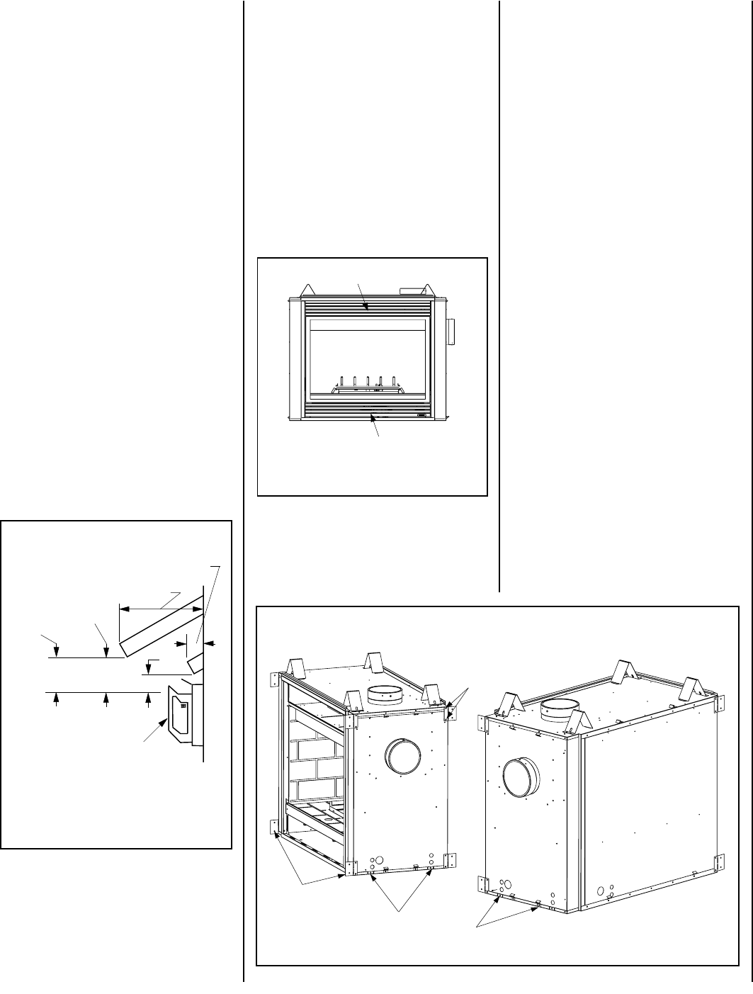
Figure 1
CDPF
CDST
Millivolt Models -
Millivolt models come standard with the
manually-modulated gas valve; flame ap-
pearance and heat output can be con-
trolled at the gas valve.
Input of millivolt models is shown in the
following table:
Electronic appliances are designed to operate
on natural or propane gas. An electronic inter-
mittent pilot ignition system provides safe,
efficient operation. External electrical power is
required to operate these units.
These appliances comply with National Safety
Standards and are tested and listed by War-
nock Hersey (Report No. J20006712) to ANSI
Z21.88-2000 (in Canada, CSA-2.33-2000), and
CAN/CGA-2.17-M91 in both USA and Canada,
as vented gas fireplace heaters.
Both millivolt and electronic versions of these
appliances are listed by Warnock Hersey for
installation in bedrooms and mobile homes.
Installation must conform to local codes. In the
absence of local codes, installation must com-
ply with the current National Fuel Gas Code,
ANSI Z223.1. (In Canada, the current CAN-1
B149 installation code.) Electrical wiring must
comply with the National Electrical Code ANSI/
NFPA 70 - (latest edition). (In Canada, the
current CSA C22-1 Canadian Electrical Code.)
TYPICAL INSTALLATION
DO NOT ATTEMPT TO ALTER OR MODIFY
THE CONSTRUCTION OF THE APPLIANCE OR
ITS COMPONENTS. ANY MODIFICATION OR
ALTERATION MAY VOID THE WARRANTY,
CERTIFICATION AND LISTINGS OF THIS UNIT.
INTRODUCTION
These fireplaces are designed, tested and listed
for operation and installation with, and only with,
Secure Vent™ Direct Vent System Components,
Secure Flex™ Flexible Vent Components manu-
factured by Security Chimneys International and
Z-Flex™ Model GA Venting Systems, listed to
UL1777 and ULCS635 manufactured by Flex-
master Canada Limited. These approved vent
system components are labeled for identifica-
tion. DO NOT use any other manufacturer's vent
components with these appliances.
The millivolt appliances are designed to operate
on either natural or propane gas. A millivolt gas
control valve with piezo ignition system pro-
vides safe, efficient operation. If any optional
accessories which require electrical power are
being installed, the electrical power must be
provided at the time of appliance installation.
GENERAL INFORMATION
Note: Installation and repair should be per-
formed by a qualified service person. The appli-
ance should be inspected annually by a quali-
fied professional service technician. More fre-
quent inspections and cleanings may be re-
quired due to excessive lint from carpeting,
bedding material, etc. It is imperative that the
control compartment, burners and circulating
air passage ways of the appliance be kept clean.
S'assurer que le brùleur et le compartiment des
commandes sont propres. Voir les instruc-
tions d'installation et d'utilisation qui
accompagnent l'appareil.
Provide adequate clearances around air open-
ings and adequate accessibility clearance for
service and proper operation. Never obstruct
the front, back and/or side viewing surfaces of
the appliance.
These appliances are designed to operate on
natural or propane gas only.
This installation manual will help you achieve a
safe, efficient and dependable installation for
your appliance and vent system. Please read
and understand these instructions be-
fore beginning your installation.
Packaging ........................................ page 2
Introduction ..................................... page 2
General Information......................... page 2
Location .......................................... page 3
Appliance and Vent Clearances ....... page 4
Vent Termination Clearances ........... page 4
Typical Installation Sequence .......... page 5
Detailed Installation Steps ............... page 5
Step 1. Framing ............................. page 5
Fireplace Specifications ................... page 8
Step 2. Routing Gas Line ............... page 10
Step 3. Install the Venting System . page 10
Vertical Termination Systems .......... page 11
Vent Section Length Chart ............... page 11
Vertical Vent Tables and Figures...... page 14
Horizontal Termination System........ page 16
Horizontal Vent Tables and Figures . page 18
Venting Using Flexible Vent Pipe ..... page 21
Step 4. Field Wiring ....................... page 22
Step 5. Optional Blower Kit Wiring page 22
Step 6. Connecting Gas Line.......... page 23
Step 7. Installing Logs, Decorative Volcanic
Stone and Glowing Embers ........... page 23
Step 8. Checking Unit Operation ..... page 23
Step 9. Installing Glass
Enclosure Panels ........................... page 24
Step 10. Burner Adjustments........... page 24
Step 11. Hood Installation ............... page 25
Finishing Requirements ................... page 25
Cold Climate Insulation.................... page 25
Installation Accessories ................... page 26
Gas Conversion Kits.................. page 28
TABLE OF CONTENTS
sledoMtlovilliM
enaporPdnalarutaN sledoMsaG
)H/UTB(etartupnI -yllaunaM detaludom
,NMC-FPDC,NMC-TSDC ,NMC-RCDC,NMC-LCDC ,PMC-FPDC,PMC-TSDC PMC-RCDC,PMC-LCDC
005,73OT000,03
PACKAGING
The assembled vented gas fireplace heater is
packaged with:
1 - one cartoned log set located in firebox area;
decorative volcanic stone and glowing em-
bers (rockwool) located inside the bottom
cabinet compartment.
2 -one envelope containing the literature
package which consists of the homeowner's
manual, installation instructions, warranty,
and 8 (CDST), 4 (CDPF, CDCR and CDCL)
nailing flanges; envelope is located on top
of the unit.
3 - one vent restrictor to be applied as shown on
page 10
; restrictor is taped to the envelope.
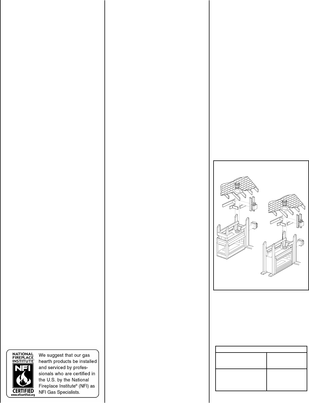
4 - two hoods (CDST, CDCR, CDCL), or three
hoods (CDPF) taped to the top of the fireplace.
NOTE: DIAGRAMS & ILLUSTRATIONS NOT TO SCALE.
3
NOTE: DIAGRAMS & ILLUSTRATIONS NOT TO SCALE.
* Each model has two burners. Each burner contains
one of these orifices.
sledoMcinortcelE
enaporPdnalarutaN sledoMsaG )H/UTB(etartupnI etaRdexiF
,NEC-FPDC,NEC-TSDC ,NEC-RCDC,NEC-LCDC ,PEC-FPDC,PEC-TSDC PEC-RCDC,PEC-LCDC
005,73
ledoM .oN
*ezisecifirO noitavelE )sretem(teeF
.taN.porP
TSDC FPDC RCDC LCDC
44#55# 0054-0 )0731-0(
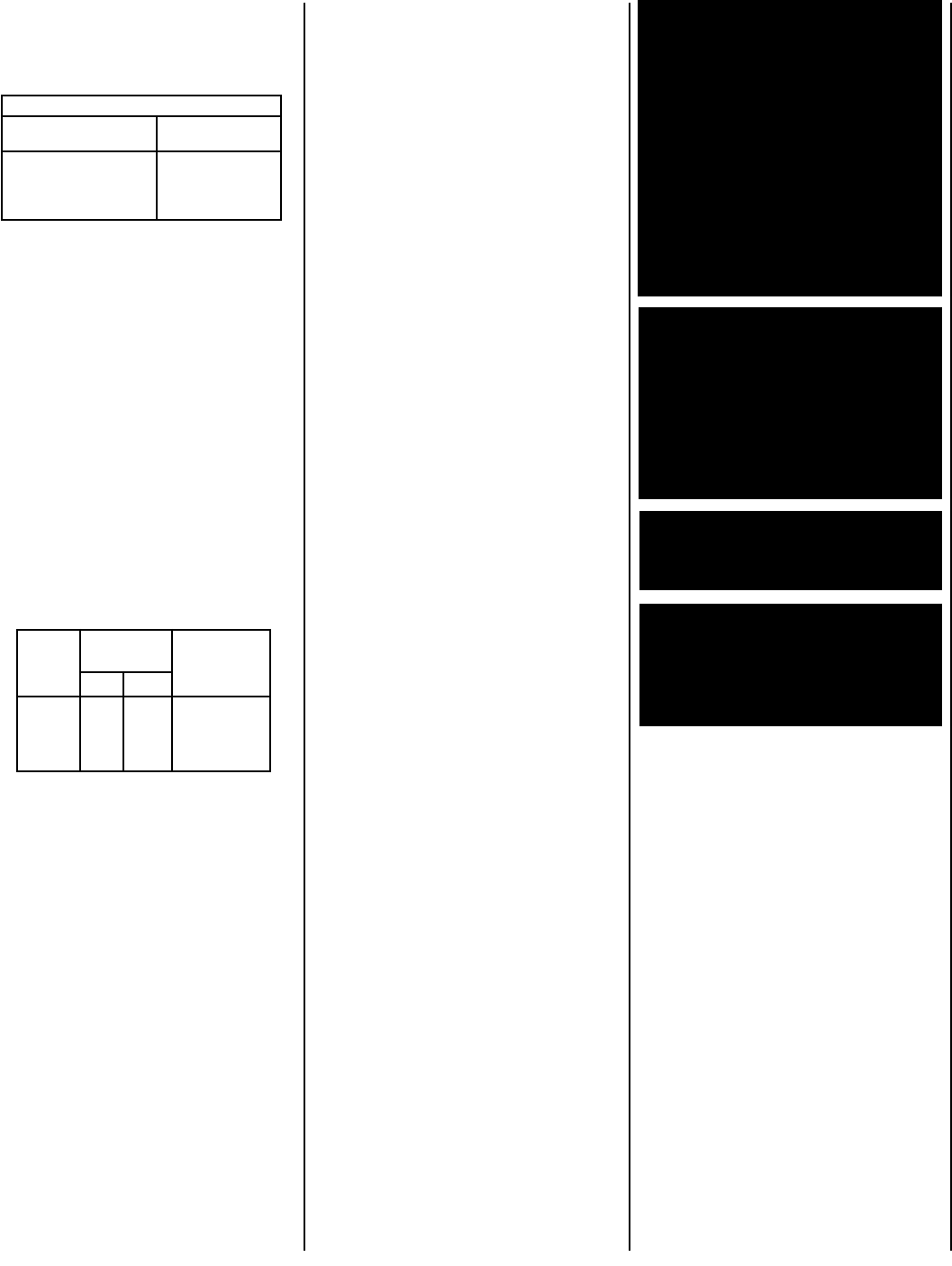
LOCATION
In selecting the location, the aesthetic and func-
tional use of the appliance are primary concerns.
However, vent system routing to the outside
atmosphere and access to the fuel supply are
also important. Consideration should be given to
traffic ways, furniture, draperies, etc., due to
high surface temperatures (
Figure 2
). The loca-
tion should also be free of electrical, plumbing or
other heating/air conditioning ducting.
These direct vent appliances are uniquely suited
for installations requiring a utility shelf posi-
tioned directly above the fireplace. Utility shelves
like these are commonly used for locating tele-
vision sets and decorative plants.
To achieve the lowest possible shelf height, use
the alternative rear vent outlet. Do not insulate
the space between the appliance and the area
above it. See
Figure 3 on page 4
. The minimum
height from the base of the appliance to the
underside of combustible materials used to con-
struct a utility shelf in this fashion is shown in the
table in
Figure 3 on page 4
. The weight of the
utility shelf and anything placed upon it may not
be supported by the appliance in anyway.
Table 1
Test gage connections are provided on the
front of the millivolt gas control valve (iden-
tified IN for the inlet and OUT for the mani-
fold side). A ¹⁄₈" NPT test gage connection
is provided at the inlet and outlet side of
the electronic gas control valve.
Minimum inlet gas pressure to these appli-
ances is 5.0 inches water column (1.24 kPa)
for natural gas and 11.0 inches water column
(2.74 kPa) for propane for the purpose of input
adjustment.
Maximum inlet gas supply pressure to these appli-
ances is 10.5 inches water column (2.61 kPa) for
natural gas and 13.0 inches water column (3.23
kPa) for propane.
These appliances must be isolated from the
gas supply piping system (by closing their
individual manual shut-off valve) during any
pressure testing of the gas supply piping sys-
tem at test pressures equal to or less than ¹⁄₂
psig (3.5 kPa).
These appliances and their individual shut-off
valves must be disconnected from the gas
supply piping system during any pressure test-
ing of that system at pressures in excess of ¹⁄₂
psig (3.5 kPa).
These appliances must not be connected to a
chimney or flue serving a separate solid fuel
burning appliance.
Do not use these appliances if any part has been
under water. Immediately call a qualified,
professional service technician to inspect the
appliance and to replace any parts of the con-
trol system and any gas control which have
been under water.
Ne pas se servir de cet appareil s'il a été
plongé dans l'eau, complètement ou en
partie. Appeler un technicien qualifié pour
inspecter l'appareil et remplacer toute partie
du système de contrôle et toute commande
qui ont été plongés dans l'eau.
The millivolt appliances are manually controlled
and feature a spark ignitor (piezo) that allows
the appliance's pilot gas to be lit without the use
of matches or batteries. This system will still
function in the event of a power outage.
Installations at Altitudes of 0 to 4500 ft.-
Units are tested and approved for elevations
of 0 to 4500 feet (0 to 1372 meters).
Installations at Altitudes above 4500 ft.-
For elevations above 4500 feet (1372
meters), install the unit according to the
regulations of the local authorities having
jurisdiction and, in the USA, the latest edition
of the National Fuel Gas Code (ANSI Z223.1)
or, in Canada, the latest edition of the
CAN1-B149.1 and .2 codes.
This appliance may be installed in an af-
termarket permanently located, manufac-
tured home (USA only) or mobile home,
where not prohibited by local codes. This
appliance is only for use with the type of
gas indicated on the rating plate. This ap-
pliance is not convertible for use with
other gases, unless a certified kit is used.
Cet appareil peut être installé dans un maison
préfabriquée (É.-U. seulement) ou mobile déjà
installée à demeure si les réglements locaux
le permettent. Cet appareil doit être utilisé
uniquement avec les types de gaz indiqués
sur la plaque signalétique. Ne pas l'utiliser
avec d'autres gaz sauf si un kit de conversion
certifié est installé.
Carbon Monoxide Poisoning: Early signs of
carbon monoxide poisoning are similar to
the flu with headaches, dizziness and/or
nausea. If you have these signs, obtain fresh
air immediately. Turn off the gas supply to
the appliance and have it serviced by a
qualified professional, as it may not be op-
erating correctly.
Electronic Models -
Electronic models have a fixed rate gas valve.
Input of electronic models is shown in the
following table:
All Models -
Maximum manifold pressure is 3.5 in. w.c.
(0.87 kPa) for natural gas and 10 in. w.c.
(2.49 kPa) for LP/Propane gas.
WARNING: FAILURE TO COMPLY WITH
THE INSTALLATION AND OPERATING IN-
STRUCTIONS PROVIDED IN THIS DOCU-
MENT WILL RESULT IN AN IMPROP-
ERLY INSTALLED AND OPERATING AP-
PLIANCE, VOIDING ITS WARRANTY. ANY
CHANGE TO THIS APPLIANCE AND/OR
ITS OPERATING CONTROLS IS DANGER-
OUS. IMPROPER INSTALLATION OR USE
OF THIS APPLIANCE CAN CAUSE SERI-
OUS INJURY OR DEATH FROM FIRE,
BURNS, EXPLOSION OR CARBON MON-
OXIDE POISONING.
WARNING: CHILDREN AND ADULTS
SHOULD BE ALERTED TO THE HAZARDS
OF HIGH SURFACE TEMPERATURES. USE
CAUTION AROUND THE APPLIANCE TO
AVOID BURNS OR CLOTHING IGNITION.
YOUNG CHILDREN SHOULD BE CARE-
FULLY SUPERVISED WHEN THEY ARE IN
THE SAME ROOM AS THE APPLIANCE.
WARNING: DO NOT PLACE CLOTHING
OR OTHER FLAMMABLE MATERIALS
ON OR NEAR THIS APPLIANCE.
AVERTISSEMENT: SURVEILLER LES
ENFANTS. GARDER LES VÊTEMENTS,
LES MEUBLES, L'ESSENCE OU AUTRES
LIQUIDES À VAPEUR INFLAMMABLES
À COTE DE L'APPAREIL.
Table 1
shows the units' gas orifice size for
the elevations indicated.
4NOTE: DIAGRAMS & ILLUSTRATIONS NOT TO SCALE.
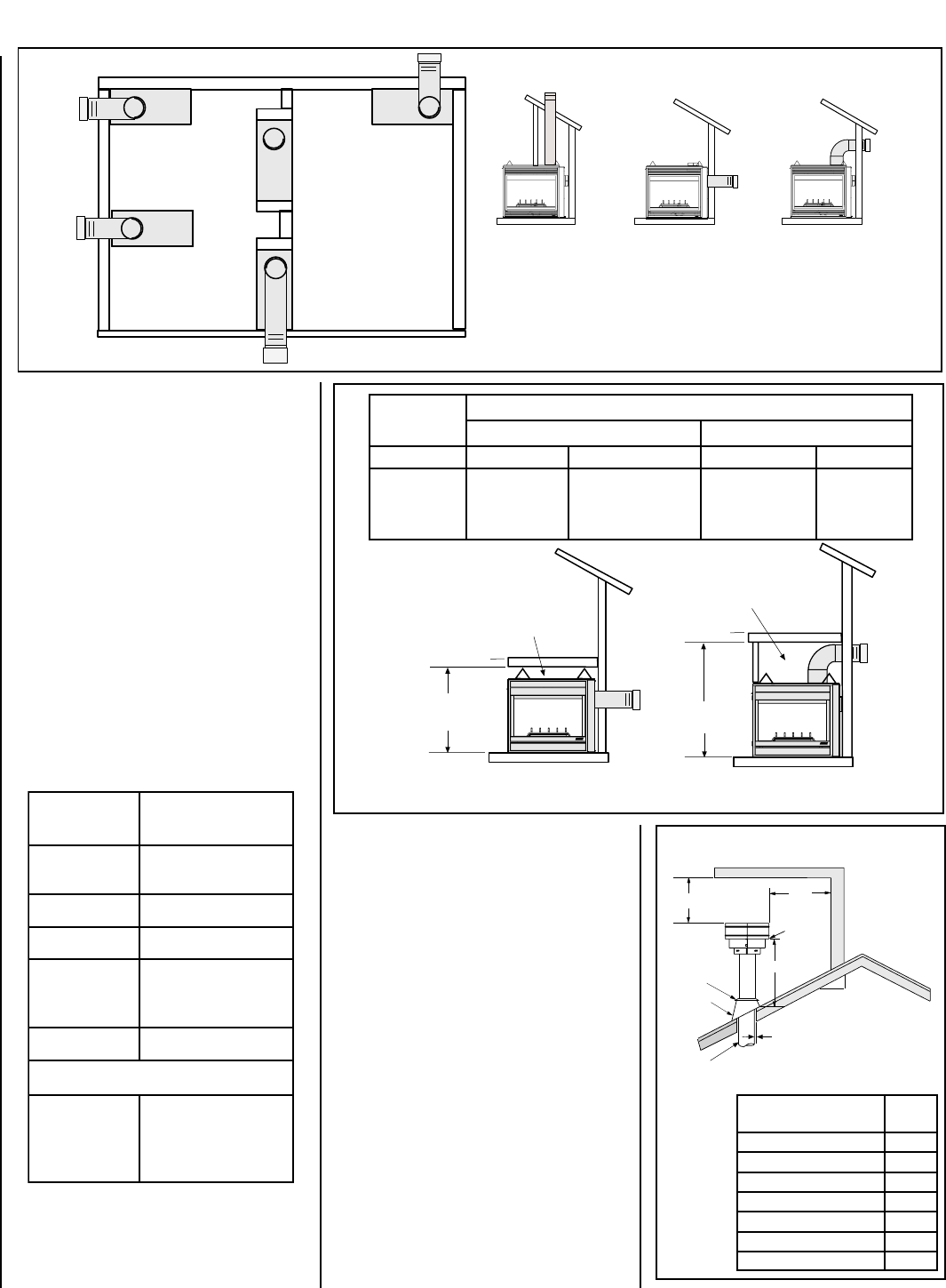
hctiPfooR H)teef(
21/6ottalF0.1
21/7ot21/6revO52.1
21/8ot21/7revO5.1
21/9ot21/8revO0.2
21/01ot21/9revO5.2
21/11ot21/01revO52.3
21/21ot21/11revO0.4
KCAB )mm31(.ni2/1 srecaps)mm0(.ni0
SEDIS )mm31(.ni2/1 srecaps)mm0(.ni0
SRECAPSPOT)mm0(.ni0
ROOLF)mm0(.ni0
mottoBmorF ottinUfo gnilieC )mm6261(.ni46
TNEV*)mm4.52(.ni1
SECNARAELCECIVRES
GNIWEIV -SEDIS KCABTNORF( )EDISRO
)sretem9.0(.teeF3
12
X
Roof Pitch is X/12
2 FT
MIN.
2 FT MIN.
Lowest
Discharge
Opening
H*
*H = MINIMUM HEIGHT FROM ROOF TO
LOWEST DISCHARGE OPENING OF VENT
TERMINATION HEIGHTS FOR VENTS ABOVE
FLAT OR SLOPED ROOFS
Horizontal Overhang
Vertical
Wall
Vent
Termination
Storm Collar
Concentric
Vent Pipe
Flashing
1 inch (25.4 mm) Minimum
Clearance to Combustibles
Figure 4
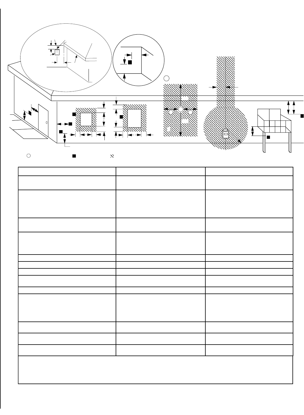
Figure 2
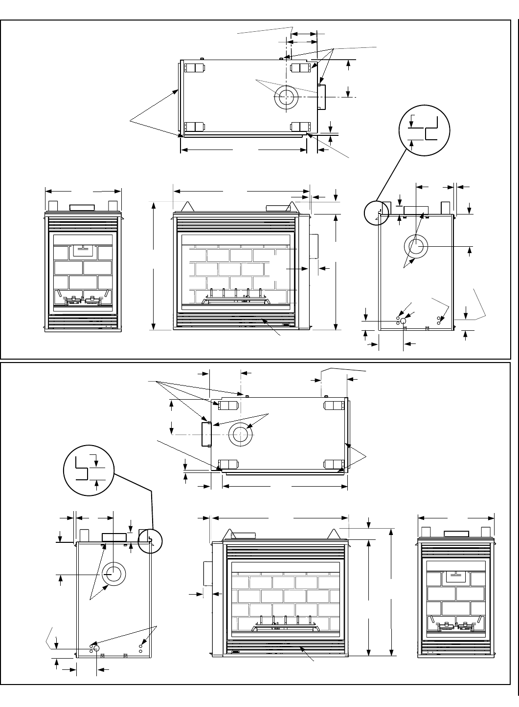
APPLIANCE AND VENT CLEARANCES
The appliance is approved with zero clearance to
combustible materials on all sides (as detailed in
Table 2 )
, with the following exception: When the
unit is installed with one side flush with a wall,
the wall on the other side of the unit must not
extend beyond the front edge of the unit. In
addition, when the unit is installed in the middle
of a room, the side walls surrounding the unit
must not extend beyond the front or rear edge
of the unit. See
Figure 2
.
The appliance should be mounted on a fully
supported base extending the full width and
depth of the unit. The appliance may be located
on or near conventional construction materi-
als. However, if installed on combustible mate-
rials, such as carpeting, vinyl tile, etc., a metal
or wood barrier covering the entire bottom
surface must be used.
Figure 3
TYPICAL LOCATIONS
VERTICAL VENT
See-Through
(CDST)
Corner - Left
(CDCL)
Corner - Right
(CDCR)
Peninsula
(CDPF)
HORIZONTAL VENT
- REAR
See-Through
(CDST) -
one side flush
with a wall
HORIZONTAL VENT
- TOP
*
Note: 3 in. (75 mm) above any horizontal/inclined
vent component.
Table 2
.oNledoM )mm(sehcnithgieHflehS
woblEeergeD09enOhtiw-tneVpoTkcaBehttuOthgiartS-tneVraeR
tneVeruceSxelFeruceStneVeruceSxelFeruceS
TSDC FPDC RCDC LCDC
2/135)9531(4/155)3041(8/114)5401(8/114)5401(
VENT TERMINATION CLEARANCES
These instructions should be used as a
guideline and do not supersede local codes
in any way. Install vent according to local
codes, these instructions, the current Na-
tional Fuel Gas Code (ANSI-Z223.1) in the
USA or the current standards of CAN/CGA-
B149.1 and -B149.2 in Canada.
Vertical Vent Termination Clearances
Terminate single vent caps relative to
building components according to
Figure 4.
Terminate multiple vent terminations accord-
ing to the installation codes listed above.
Horizontal Vent Termination Clearances
See
Figure 5 on page 5
for horizontal vent
termination clearances to any overhead com-
bustible projection less than or equal to 2 ¹⁄₂"
(64 mm) and greater than 2¹⁄₂" (64 mm). For
additional vent location restrictions refer to
Figure 8 on page 6
.
Shelf Above Fireplace
With Rear Venting
Do not insulate the
space between the
appliance and the
area above it.
Shelf Height
(see table)
Shelf Above Fireplace
With Top Venting
Do not insulate the
space between the
appliance and the
area above it.
Shelf Height
(see table)
5
NOTE: DIAGRAMS & ILLUSTRATIONS NOT TO SCALE.
3"
(76 mm)
12"
(305 mm)
Termination
Kit
Combustible Projection
greater than 2¹⁄₂ inches in length
Horizontal Vent Termination Clearances
Combustible Projection
2¹⁄₂ inches or less in length
18"
(457 mm)
Ventilated
Soffit
Unventilated
Soffit
Top Louver Panel
Unit Parts Identification
Control Compartment Access Panel
Figure 5 -
Side Elevation View
Figure 6
Note - See Figure 39 on page 17 for the exterior
wall recess allowances of the square horizontal
termination.
TYPICAL INSTALLATION SEQUENCE
The typical sequence of installation follows,
however, each installation is unique resulting in
variations to those described.
See the page numbers references in the follow-
ing steps for detailed procedures.
Step 1. (page 5) Construct the appliance
framing. Position the appliance within the
framing and secure with nailing brackets.
Step 2. (page 10) Route gas supply line to
appliance location.
Step 3. (page 10) Install the vent system and
exterior termination.
Step 4. (page 22) Field Wiring
A. Millivolt Appliances – The operating control
switch is factory installed.
B. Electronic Appliances – Connect 120 Vac
electrical power to the appliance receptacle.
Step 5. (page 22) Install blower kit (optional
equipment).
Step 6. (page 23) Make connection to gas
supply.
Step 7. (page 23) Install the log set, decora-
tive volcanic stone and glowing embers.
Step 8. (page 23) Checkout appliance op-
eration.
Step 9. (page 24) Install glass enclosure
panels.
Step 10. (page 24) Adjust burner primary air
shutter to achieve proper flame appearance.
Step 11. (page 25) Install the hoods.
Side Nailing Flanges
The fireplace should be secured to the framing
at the side(s) and/or rear of the unit using the
factory-provided nailing flanges. Install the
nailing flanges - 8 (CDST), 4 (CDPF, CDCL and
CDCR) - as shown in
Figure 7
using the
existing screws. Position the fireplace within
the framing. When required, the flanges may
be bent 90 degrees by hand or with the assis-
tance of a hammer. Use wood screws to
secure the nailing flanges to the framing.
See
Table 2 on page 4
for clearances of framing
members to cabinet parts in the nailing flange
area. The nailing flange itself is exempt from
these clearances.
Floor Nailing Tabs
Secure the fireplace to the floor as shown in
Figure 7.
Turn tabs down and secure to the floor with
8d nails or other appropriate fasteners
on all sides of the unit which do not have
viewing glass panels.
CDST SHOWN
(CDPF - NO NAILING FLANGES
ON END WITH GLASS PANEL) CDCL SHOWN
(FOR CDCR VIEW, INTERCHANGE SIDES)
Remove these two screws and
use them when installing
the nailing flanges.
Nailing Flanges
Figure 7
DETAILED INSTALLATION STEPS
3 - Lift the pressure relief plates and remove
the cardboard from underneath each of them.
4 - Open the control compartment access panel
by actuating the spring loaded magnetic catches
securing the panel, gently depressing the outer
top corners of the panel until the catches "pop"
the panel free, allowing it to swing out and
down to open.
5 - Open the two latches (located under the
firebox floor) securing the glass enclosure
panel. Remove the panel by tilting it outward at
the bottom and lifting it up. Set the door aside
protecting it from inadvertent damage.
See
Figure 57 on page 24.
The appliance is shipped with all gas controls
and components installed and pre-wired.
1 - Remove the shipping carton.
2 - Remove the top louver panel
(see Figure 6)
.
Note: The CDST fireplace is installed in the
framing by cocking it at an angle, fitting the
collar side in first and then twisting and pushing
the other side in. To minimize the obstruction,
it is helpful to make sure the cap is removed
from the rear collar.
If the appliance is to be elevated above floor level,
a solid continuous platform must be constructed.
Headers may be in direct contact with the appli-
ance top spacers but must not be supported by
them or notched to fit around them. All construc-
tion above the appliance must be self supporting,
DO NOT use the appliance for structural support.
All framing details must allow for a mini-
mum clearance to combustible framing
members as shown in
Table 2 on page 4
.
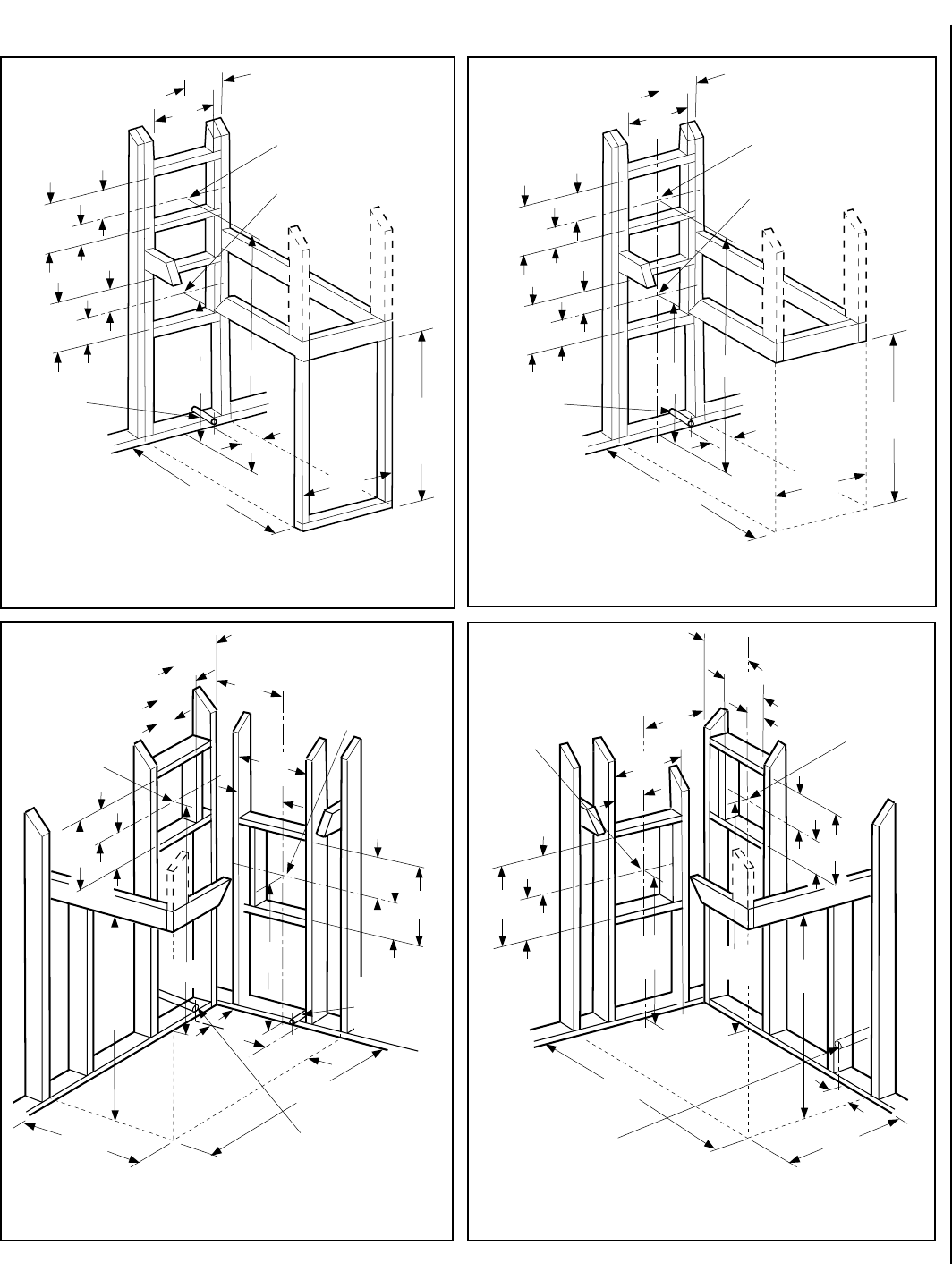
Step 1. FRAMING
Frame these appliances as illustrated in
Figures 9 (CDST), 10 (CDPF), 11 (CDCL)
or 12 (CDCR).
6NOTE: DIAGRAMS & ILLUSTRATIONS NOT TO SCALE.
Figure 8
EXTERIOR HORIZONTAL VENT TERMINATION CLEARANCE REQUIREMENTS
*noitallatsnInaidanaC**noitallatsnISU
,hcrop,adnarev,edargevobaecnaraelC=A .ynoclabro,kced *)mc03(sehcni21**)mc03(sehcni21
ebyamtahtroodrowodniwotecnaraelC=B .denepo secnailpparof)mc51(ni6 )mc03(ni21,)Wk3(hutB000,01< dna)Wk3(hutB000,01>secnailpparof )mc19(sehcni63,)Wk03(hutB000,001< *)Wk03(hutB000,001>secnailpparof
secnailpparof)mc51(ni6 )mc32(ni9,)Wk3(hutB000,01< dna)Wk3(hutB000,01>secnailpparof )mc03(sehcni21,)Wk51(hutB000,05< **)Wk51(hutB000,05>secnailpparof
wodniwdesolcyltnenamrepotecnaraelC=C wodniwtneverpotmuminim)mm503("21 noitasnednoc wodniwtneverpotmuminim)mm922("9 noitasnednoc
tiffosdetalitnevotecnaraelclacitreV=D latnozirohanihtiwlanimretehtevobadetacol retnecehtmorf)mm854(sehcni81foecnatsid lanimretehtfoenil
)mm854("81)mm854("81
tiffosdetalitnevnuotecnaraelC=E)mm503("21)mm503("21
renrocedistuootecnaraelC=Fmuminim)mc7.21("5muminim)mc7.21("5
renrocedisniotecnaraelC=Gmuminim)mc2.51("6muminim)mc2.51("6
enilretnecfoedisnihcaeotecnaraelC=H ylbmessarotaluger/retemevobadednetxe teef51fothgiehanihtiw)mc19(teef3 *ylbmessarotaluger/retemehtevoba teef51fothgiehanihtiw)mc19(teef3 **ylbmessarotaluger/retemehtevoba
teltuotnevrotalugerecivresotecnaraelC=I*)mc19(teef3**)mc19(teef3
telniylppusrialacinahcemnonotecnaraelC=J ynaottelnirianoitsubmocehtrognidliubot ecnailpparehto
secnailpparof)mc51(ni6 )mc03(ni21,)Wk3(hutB000,01< dna)Wk3(hutB000,01>secnailpparof )mc19(sehcni63,)Wk03(hutB000,001< *)Wk03(hutB000,001>secnailpparof
secnailpparof)mc51(ni6 )mc32(ni9,)Wk3(hutB000,01< dna)Wk3(hutB000,01>secnailpparof )mc03(sehcni21,)Wk51(hutB000,05< **)Wk51(hutB000,05>secnailpparof
telniylppusrialacinahcemaotecnaraelC=K*)m38.1(teef6 )m3(teef01nihtiwfievoba)mc19(teef3 **yllatnoziroh
devaproklawedisdevapevobaecnaraelC=L ytreporpcilbupnodetacolyawevid ‡)m31.2(teef7 ‡)m31.2(teef7
rokced,hcrop,adnarevrednuecnaraelC=M ynoclab ‡*)mc03(sehcni21 ‡)mc03(sehcni21
V
VV
V
V
F
C
Fixed
Closed
Window
Operable
Window
B
B
A
B
H
M
I
= Vent Terminal = Area where Terminal is not Permitted
= Air Supply Inlet
XV
D
V
3 ft.
3 ft.
AA
A
= 9” in U.S.
= 12” in Canada
V
L
B
J
XE
V
A
G
Inside
Corner Detail
*18”
Ventilated Soffit
Horizontal
Termination
Detail D
Exterior Wall Center Line
of Termination
18”
Inside Corner
B
C
C
C
* See Item D in the Text Below.
.edoCnoitallatsnIenaporPdnAsaGlanoitaN1.941B-ASCtnerrucehthtiwecnadroccanI* .sedoCsaGleuFlanoitaN45APFN/1.322ZSISNAtnerucehthtiwecnadroccanI** sevresdnasgnillewdylimafelgnisowtneewtebdetacolsihcihwyawevirddevaproklawedisaevobayltceridetanimrettonllahstnevA‡.sgnillewdhtob :roolfehthtaenebsedis2muminimanonepoyllufsiynoclabrokced,hcrop,adnarevfidettimrepylnO‡*
7
NOTE: DIAGRAMS & ILLUSTRATIONS NOT TO SCALE.
Gas Line
Center of gas line
is 3 in. (76 mm)
up from floor.
*41¹⁄₂
(1054)
48¹⁄₂
(1108)
*This dimension can be reduced to 41 inches (1041 mm). This
results in 0 in. (0 mm) clearance between framing and unit framing
spacers. (The 41¹⁄₂ in. dimension permits easier fireplace
installation, if unit is installed after framing is erected.)
26³⁄₄
(679)
11³⁄₈
(267)
Dimension A
Secure Vent - 46 (1168)
Secure Flex - 47 ³⁄₄ (1213)
7
(178)
5¹⁄₈
(130)
12¹⁄₈
(308)
10¹⁄₂
22³⁄₄
(578)
CDST
(See-Through)
VENT FRAMING -
TOP VENT WITH
ONE 90º ELBOW
VENT FRAMING -
REAR VENT WITH
NO ELBOWS
inches (millimeters)
6¹⁄₄
(159)
A
Minimum Framing
Stud Size is 2x4
7
(178)
5¹⁄₈
(130)
12¹⁄₈
(308)
*41¹⁄₂
(1054)
43⁵⁄₈
(1108)
*This dimension can be reduced to 41 inches (1041 mm). This results
in 0 in. (0 mm) clearance between framing and unit framing spacers.
(The 41¹⁄₂ in. dimension permits easier fireplace installation, if unit
is installed after framing is erected.)
26³⁄₄
(679)
11³⁄₈
(267)
7
(178)
5¹⁄₈
(130)
12¹⁄₈
(308)
10¹⁄₂
22³⁄₄
(578)
CDPF (Peninsula)
VENT FRAMING -
TOP VENT WITH
ONE 90º ELBOW
VENT FRAMING -
REAR VENT WITH
NO ELBOWS
inches (millimeters)
Gas Line
Center of gas line
is 3 in. (76 mm)
up from floor.
6¹⁄₄
(159)
A
Minimum Framing
Stud Size is 2x4
7
(178)
12¹⁄₈
(308)
5¹⁄₈
(130)
Dimension A
Secure Vent - 46 (1168)
Secure Flex - 47 ³⁄₄ (1213)
*41¹⁄₂
(1054)
43⁵⁄₈
(1108)
*This dimension can be reduced to 41 inches (1041 mm). This results
in 0 in. (0 mm) clearance between framing and unit framing spacers.
(The 41¹⁄₂ in. dimension permits easier fireplace installation, if unit
is installed after framing is erected.)
26³⁄₄
(679)
10¹⁄₂
(267)
12¹⁄₂
(318)
7
(178)
5¹⁄₈
(130)
12¹⁄₈
(308)
10¹⁄₂
(267)
10³⁄₈
(264)
5¹⁄₄
(133)
5¹⁄₄ (133)
24
(610)
CDCL (Corner-Left)
VENT FRAMING -
TOP VENT WITH
ONE 90º ELBOW
VENT FRAMING -
REAR VENT WITH
NO ELBOWS
inches (millimeters)
6¹⁄₄
(159)
9³⁄₄
(248)
Optional Gas Line Location
Center of gas line is
3 in. (76 mm) up from floor.
A
Gas Line
Center of gas line
is 3 in. (76 mm)
up from floor.
Minimum Framing
Stud Size is 2x4
7
(178)
5¹⁄₈
(130)
12¹⁄₈
(308)
Dimension A
Secure Vent - 46 (1168)
Secure Flex - 47 ³⁄₄ (1213)
*41¹⁄₂
(1054)
43⁵⁄₈
(1108)
24
(610)
*This dimension can be reduced to 41 inches (1041 mm). This results
in 0 in. (0 mm) clearance between framing and unit framing spacers.
(The 41¹⁄₂ in. dimension permits easier fireplace installation, if unit is
installed after framing is erected.)
26³⁄₄
(679)
10¹⁄₂
(
267
)
12¹⁄₂
(318)
7
(178)
5¹⁄₈
(130)
12¹⁄₈
(308)
10¹⁄₂
(
267
)
10³⁄₈
(
264
)
5¹⁄₄
(133)
CDCR (Corner-Right)
VENT FRAMING -
TOP VENT WITH
ONE 90º ELBOW
VENT FRAMING -
REAR VENT WITH
NO ELBOWS
inches (millimeters)
Gas Line Center of
gas line is 3 in. (76 mm)
up from floor.
9⁷⁄₈
(251)
A
Minimum Framing
Stud Size is 2x4
5¹⁄₄
(133)
7
(178)
5¹⁄₈
(130)
12¹⁄₈
(308)
Dimension A
Secure Vent - 46 (1168)
Secure Flex - 47 ³⁄₄ (1213)
Figure 10
Figure 9
Figure 11 Figure 12
FIREPLACE FRAMING SPECIFICATIONS
8NOTE: DIAGRAMS & ILLUSTRATIONS NOT TO SCALE.
CDPF (Peninsula)
12 (305)
10
(254)
TOP VIEW
40¹⁄₈
(1019) 3¹⁄₂ (89)
⁵⁄₈
(16)
Stepped to Accept Drywall on Two Corners
FRAMING SPACERS
(Top and Side)
FINISH WALL BRACKET
(Front, back, and left edge of unit top)
6⁷⁄₈
(175)
10¹⁄₄
(260)
12
(305)
(63.5)
RIGHT SIDE VIEW
3 (76)
(13)
DETAIL OF
FINISH WALL BRACKET
FLUE
(Top or Side)
2¹⁄₂
¹⁄₂
NOTE - Unit has a factory-installed
vent seal cap and vent cover plate
(see Figures 17 and 18 on page 10)
in each flue outlet. The vent seal
cap is not shown in this figure.
24
(610)
41
(1041)
37
(940)
43⁵⁄₈
(1108) ¹⁄₂ (13)
FRONT VIEW
4 (102)
GAS INLET
ELECTRICAL
INLETS
CONTROL COMPARTMENT
ACCESS PANEL
2¹⁄₂
(63.5)
LEFT SIDE VIEW
FLUE
(Top or Side)
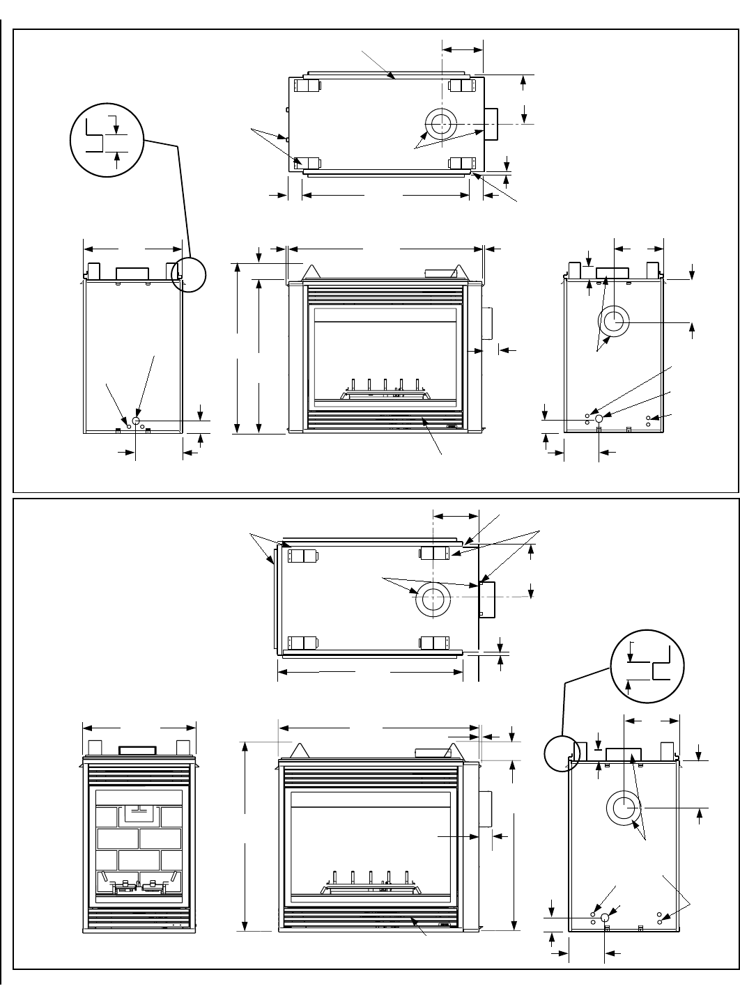
Figure 13
Figure 14
CDST (See-Through)
6⁷⁄₈
(175)
10¹⁄₄
(260)
12
(305)
12 (305)
10
(254)
(63.5)
RIGHT SIDE VIEWLEFT SIDE VIEW
TOP VIEW
3 (76)
FLUE
(Top or Side)
10¹⁄₂
(267)
FLUE
(Top or Side)
GAS INLET
ELECTRICAL
INLETS
GAS INLET
40¹⁄₈
(1019)
⁵⁄₈
(16)
Stepped to Accept Drywall on All 4 Corners
3¹⁄₂ (89)
3
(76)
ELECTRICAL
INLETS
NOTE - Unit has a factory-installed
vent sea cap and vent cover plate
(see Figures 17 and 18 on page 10)
in each flue outlet. The vent seal
cap is not shown in this figure.
FRAMING SPACERS
(Top and Both Sides)
24
(610)
FINISH WALL BRACKET
(Front and back edge of unit top)
1/2
(13)
DETAIL OF
FINISH WALL
BRACKET 3¹⁄₂ (89)
2¹⁄₂
ELECTRICAL
INLETS
CONTROL
COMPARTMENT
ACCESS PANEL
FRONT VIEW
(940)
37
41
(1041)
4 (102)
¹⁄₂ (13)
(1197)
47¹⁄₈
¹⁄₂ (13)
2¹⁄₂
(63.5)
FIREPLACE SPECIFICATIONS
9
NOTE: DIAGRAMS & ILLUSTRATIONS NOT TO SCALE.
CDCL (Corner-Left)
CDCR
(Corner-Right)
6⁷⁄₈
(175)
10¹⁄₄
(260)
12
(305)
12
(305)
10
(254)
(63.6)
RIGHT SIDE VIEW
TOP VIEW
3 (76)
FLUE
(Top or Side)
40¹⁄₈
(1019) 3¹⁄₂
(89)
FLUE
(Top or Side)
GAS INLET
ELECTRICAL
INLETS
⁵⁄₈
(16)
Stepped to
Accept
Drywall
FRAMING SPACERS
(Top, Side and Back)
(13)
DETAIL OF FINISH
WALL BRACKET
(13)
FINISH WALL BRACKET
(Front and left edge of unit top)
¹⁄₂
2¹⁄₂ ¹⁄₂
9¹⁄₄
(235)
OPTIONAL GAS INLET
OPTIONAL
GAS INLET AT
CABINET REAR
3 (76)
NOTE - Unit has a factory-installed
vent seal cap and vent cover plate
(see Figures 17 and 18 on page 10)
in each flue outlet. The vent seal cap
is not shown in this figure.
24
(610) 43⁵⁄₈
(1108) (13)
¹⁄₂
4 (102)
(940)
37
(63.6)
2¹⁄₂
41
(1041)
CONTROL COMPARTMENT
ACCESS PANEL
FRONT VIEW
LEFT SIDE VIEW
FLUE
(Top or Side)
6⁷⁄₈
(175)
10¹⁄₄
(260)
12
(305)
2¹⁄₂
(63.5)
3 (76)
FLUE
(Top or Side)
(13)
12 (305)
10
(254)
LEFT SIDE VIEW
TOP VIEW
40¹⁄₈
(1019)
3 ¹⁄₂ (89)
ELECTRICAL
INLETS
5/8
(16)
Stepped
to Accept
Drywall
FRAMING SPACERS
(Top, Side and Back)
(13)
DETAIL OF
FINISH WALL
BRACKET
FINISH WALL BRACKET
(Front and right edge of unit top)
¹⁄₂
¹⁄₂
9⁷⁄₈
(251)
Gas Line Location
GAS INLET
AT REAR
OF UNIT
NOTE - Unit has a factory-installed
vent seal cap and vent cover plate
(see Figures 17 and 18 on page 10)
in each flue outlet. The vent seal cap
is not shown in this figure.
¹⁄₂
(13) 43⁵⁄₈
(1108)
4 (102)
(940)
37
41
(1041)
CONTROL COMPARTMENT
ACCESS PANEL
FRONT VIEW
2¹⁄₂
(63.5)
24
(610)
RIGHT SIDE VIEW
Figure 15
Figure 16
FIREPLACE SPECIFICATIONS CONTINUED
10 NOTE: DIAGRAMS & ILLUSTRATIONS NOT TO SCALE.
VENT RESTRICTOR INSTALLATION
(REAR VENT)
RESTRICTOR
APPLIANCE SIDE
VENT OUTLET
VENT RESTRICTOR INSTALLATION
(TOP VENT)
RESTRICTOR
APPLIANCE TOP
VENT OUTLET
Figure 19
Figure 20
Select Venting System - Horizontal or Vertical
With the appliance secured in framing, deter-
mine vent routing and identify the exterior termi-
nation location. The following sections describe
vertical (roof) and horizontal (exterior wall) vent
applications. Refer to the section relating to your
installation. A list of approved venting compo-
nents is shown in the two tables on page 27.
A vent restrictor may be needed with this
appliance, install a vent restrictor (provided)
in the appliance top flue outlet as shown in
Figure 19
or side flue outlet as shown in
Figure 20
when vertically terminating the vent
system above the roof. It may be installed
either from inside or outside the unit, in the
inner fireplace collar. It is press-fitted in place.
Step 2. ROUTING GAS LINE
Route a ¹⁄₂" (13 mm) gas line as shown in
Figure
9 (CDST), 10 (CDPF), 11 (CDCL) or 12 (CDCR)
on pages 8 and 9
. Gas lines must be routed,
constructed and made of materials that are in
strict accordance with local codes and regula-
tions. All appliances are factory-equipped with
a flexible gas line connector and ¹⁄₂ inch shutoff
valve. (See step 6 on page 23).
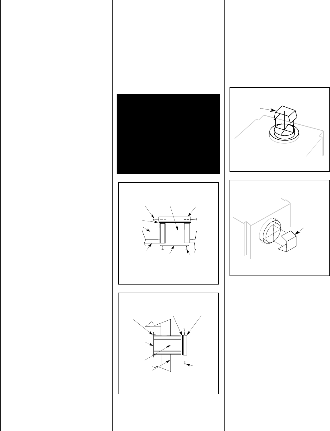
TOP VENT SEAL CAP & COVER PLATE
REMOVAL WHEN USING THE TOP VENT
VENT SEAL CAP
FIREBOX TOP
CABINET TOP
SECURING SCREWS
VENT COVER PLATE
TOP VENT
COVER PLATE
SECURING SCREW
CROSS SECTION
(INSIDE UNIT)
(OUTSIDE UNIT)
INSULATION
VENT SEAL CAP
SECURING
SCREWS
CROSS SECTION
REAR VENT
COVER PLATE
SECURING SCREWS
CABINET BACK
(INSIDE UNIT)
(OUTSIDE UNIT)
INSULATION
COVER PLATE
REAR VENT SEAL CAP & COVER PLATE
REMOVAL WHEN USING THE REAR VENT
Figure 17
Figure 18
Step 3. INSTALL THE VENT SYSTEM
GENERAL INFORMATION
These instructions should be used as a guide-
line and do not supersede local codes in any
way. Install vent according to local codes,
these instructions, the current National Fuel
Gas Code (ANSI-Z223.1) in the USA or the
current standards of CAN/CGA-B149.1 and -
B149.2 in Canada.
These fireplaces are designed, tested
and listed for operation and installation
with, and only with, Secure Vent™ Direct
Vent System Components, Secure Flex™
Flexible Vent Components manufactured
by Security Chimneys International and
Z-FLEX™ Model GA Venting Systems listed
to UL1777 and ULCS635 manufactured by
Flexmaster Canada Limited. These ap-
proved vent system components are la-
beled for identification.
DO NOT use
any other manufacturer's vent com-
ponents with these appliances.
These fireplaces must be vented directly
to the outside.
The vent system must not service multiple
appliances, and must never be connected to a
flue serving a solid fuel burning appliance. The
vent pipe is tested to be run inside an enclo-
sure (such as a chase). There is no require-
ment for inspection openings in the enclosure
at any of the joints in the vent pipe.
Preparing the Appliance Vent Collar
Each of the unit's two vent collars are sealed
with a cover plate and a seal cap. The cover
plate and seal cap must be removed from the
vent collar being used. Refer to
Figure 17
for
top vent usage and
Figure 18
for rear, and the
following steps to prepare the appropriate
collar for use.
From the vent collar being used, remove the
two screws securing the vent cap. Twist the
cap counterclockwise. Pull it away from the
unit and discard, along with the piece of
insulation.
Preparing the Appliance Top or Rear Vent
Outlet when vertically terminating the vent
system above the roof
When the top vent collar is being used, from
inside the firebox, loosen the two screws in the
keyhole slots of the cover plate and remove the
remaining two cover plate securing screws.
Remove and discard the cover plate. Reinstall
and securely tighten all four screws.
When the rear vent collar is being used, from
inside the firebox, loosen the two screws in the
keyhole slots of the cover plate and remove the
remaining two cover plate securing screws.
Remove and discard the cover plate. Reinstall
and securely tighten all four screws.
WARNING: FAILURE TO REINSTALL
AND SECURELY TIGHTEN COVER PLATE
SCREWS COULD RESULT IN LEAKAGE
OF FLUE PRODUCTS INTO THE LIVING
SPACE. VENT COVER PLATE AND VENT
SEAL CAP MUST REMAIN SECURELY
INSTALLED ON UNUSED VENT COLLAR.
FAILURE TO DO SO COULD RESULT IN
LEAKAGE OF FLUE PRODUCTS INTO
LIVING SPACE.
11
NOTE: DIAGRAMS & ILLUSTRATIONS NOT TO SCALE.
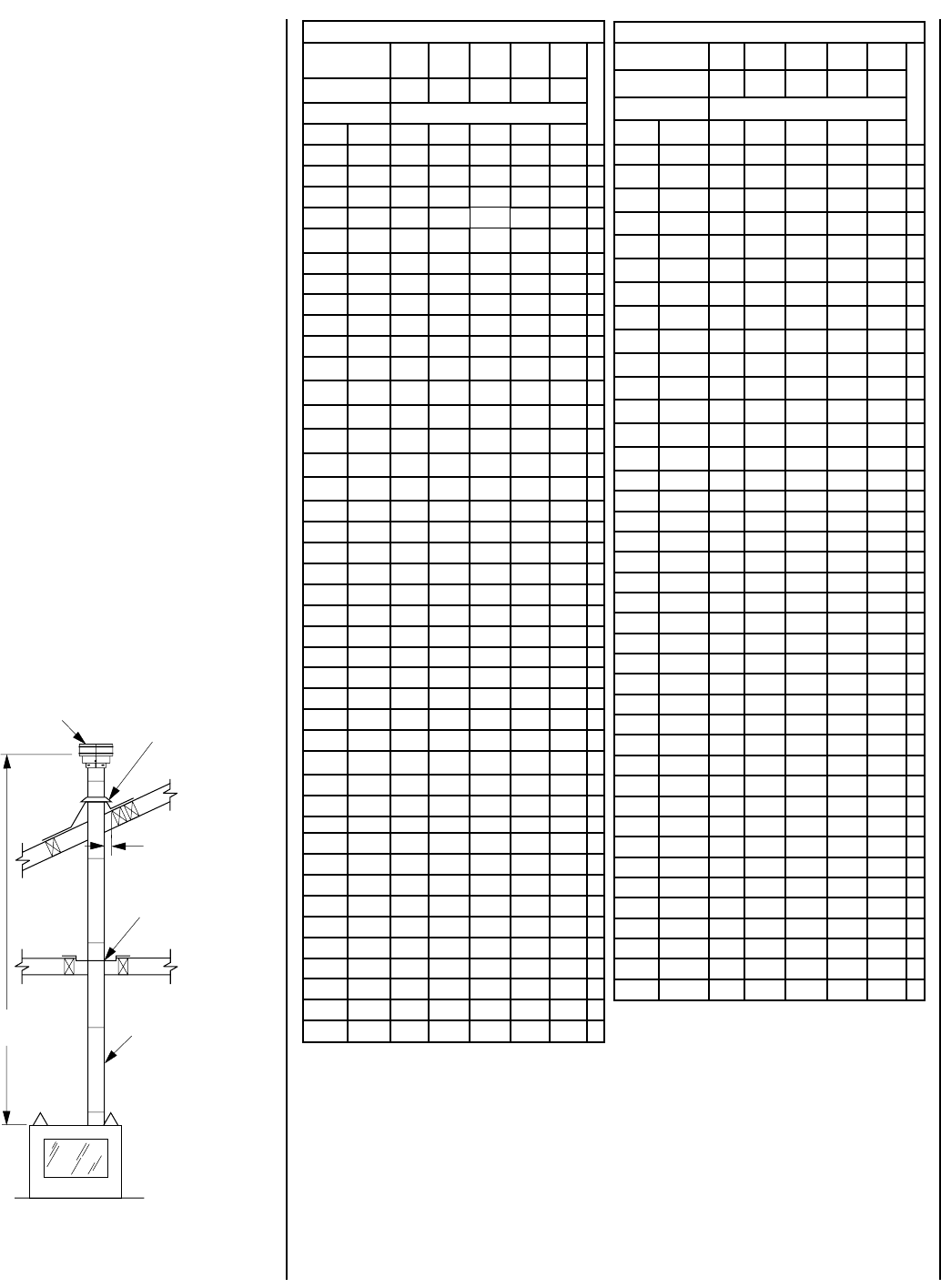
TRAHCHTGNELNOITCESTNEV
lanimoN htgneLnoitceS )sehcni( 621426384T
O
T
A
L
Q
T
Y
noitceSteN )sehcni(htgneL 2/1-42/1-012/1-222/1-432/1-64
tneVfothgieHsnoitceStneVforebmuN
sehcnitf
5.4573.0100001
957.0200002
5.01578.0010001
5152.1110002
5.91526.12100
03
1257.1020002
5.22578.1001001
5.52521.2120003
5.13526.2030003
5.43578.2000101
5.73521.3111003
5.34526.3021003
5457.3002002
5.64578.3000011
5.94521.4102003
1552.4100012
5.55526.4012003
7557.4001102
6652.5022004
5.76526.5003003
9657.5000202
27 6103004
5.37521.6100203
5.97526.6010203
1857.6000112
095.7021014
5.19526.7002013
3957.7000022
69 8101204
5.79521.8100023
2015.8200024
5.301526.8000303
801 9100304
4115.9020024
71157.9105006
5.811578.9110305
6215.01001304
5.031578.01101305
53152.11006006
8315.11000404
5.931526.11000033
5.241578.11100405
TRAHCHTGNELNOITCESTNEV
noitceSlanimoN )sehcni(htgneL 621426384T
O
T
A
L
Q
T
Y
noitceSteN )sehcni(htgneL 2/1-42/1-012/1-222/1-432/1-64
tneVfothgieHsnoitceStneVforebmuN
sehcnitf
44121100034
0515.21010034
5.451578.21110035
5.061573.31020035
5.271573.41000505
77157.41100506
38152.51010506
6815.51000044
5.091578.51100045
5.691573.61010045
5.502521.71011507
70252.71000606
5.112526.71100607
5.712521.81010607
5.922521.91001607
5.232573.91000055
73257.91100056
5.142521.02000707
6425.02100708
25212010708
46222001708
67232000808
97252.32000066
5.082573.32100809
5.382526.32100067
5.982521.42010067
5.103521.52001067
5.013578.52000909
5135.621009001
5.523521.72000077
0335.72100078
63382010078
54357.8200001001
5.943521.9210001011
27313000088
5.673573.13100089
5.973526.1300011011
5.814578.43000099
32452.531000901
56457.8300000101
SV4.5CGV-1
Termination SV4.5FA OR
SV4.5FB Flashing
AND SV4.5SC
STORM COLLAR
*SV4.5VF
Firestop/Spacer
SV4.5L6/12/24/36/48
Vent Sections
40' Max
(12.2 M)
1" (25.4 mm)
Minimum
Clearance to
Combustibles
*When using Secure Flex,
use Firestop/Spacer
SF4.5VF
Figure 21
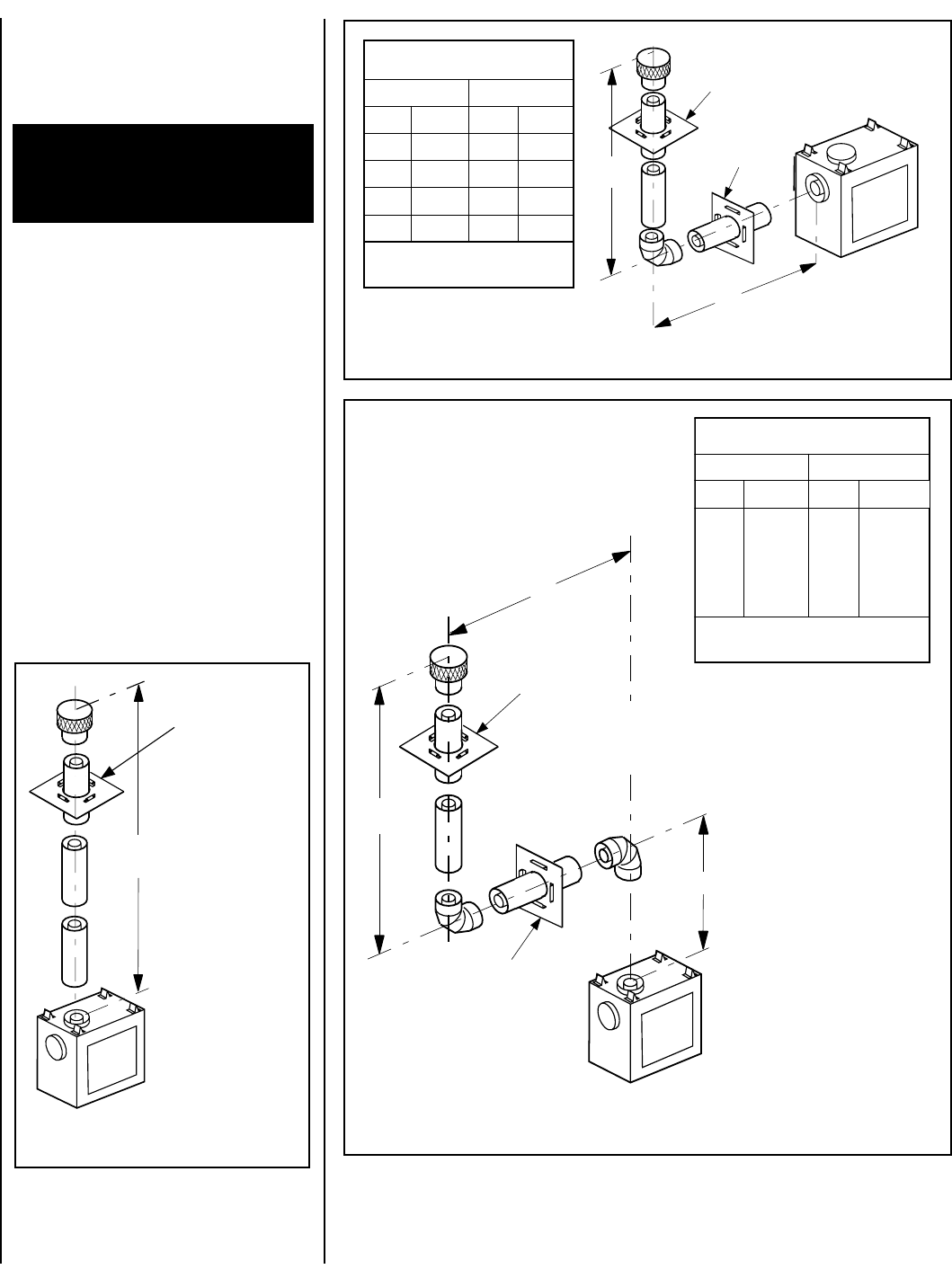
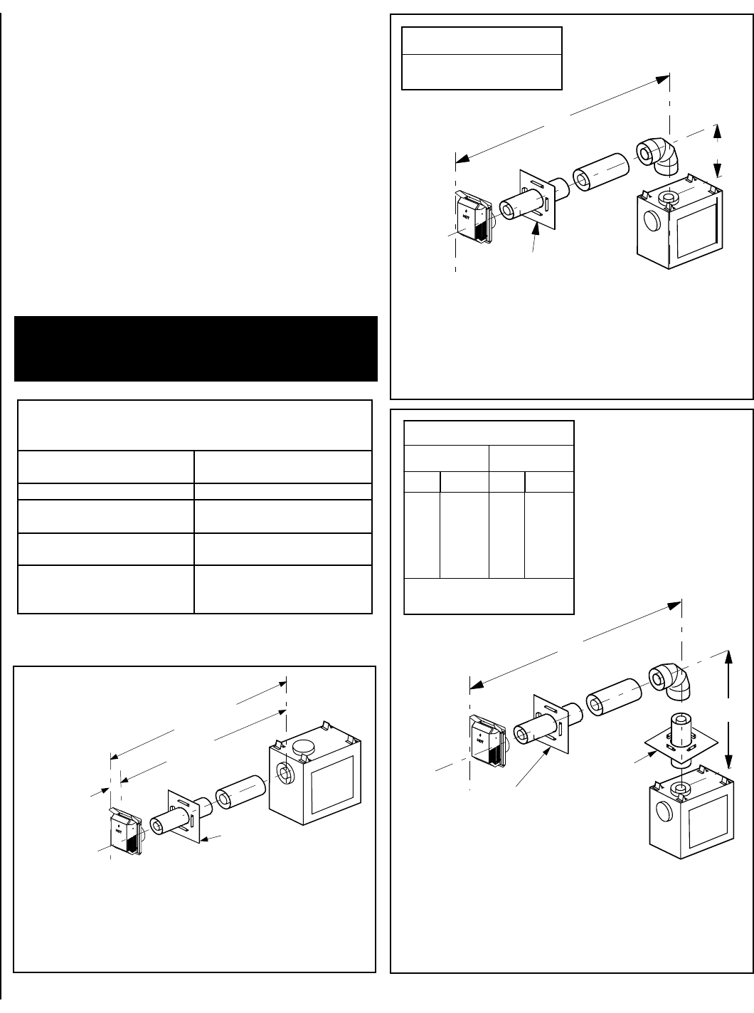
VERTICAL TERMINATION SYSTEMS (ROOF)
Figure 21, and Figures 32 through 36 on
pages 14 and 15
and their associated Vertical
Vent Tables illustrate the vertical venting con-
figurations that are allowed to be used with these
appliances. Secure Vent pipe applications are
shown in these figures; Secure Flex pipe may
also be used.
See page 21
. A Vertical Vent Table
summarizes each system’s minimum and maxi-
mum vertical and horizontal length values that
can be used to design and install the vent com-
ponents in a variety of applications.
Both these vertical vent systems terminate
through the roof. In the USA, the minimum
vent height above the roof and/or adjacent
walls is specified in ANSI Z223.1(latest edi-
tion); in Canada, by the current CAN-1 B149
installation code. It is also specified in major
building codes. Always consult your local
codes for specific requirements. A general
guide to follow is the Gas Vent Rule (refer to
Figure 4
on page 4).
Vertical (Straight) Installation
Determine the number of straight vent sections
required. 4 ¹⁄₂" (114 mm), 10 ¹⁄₂" (267 mm), 22
¹⁄₂" (572 mm), 34 ¹⁄₂" (876 mm) and 46 ¹⁄₂" (1181
mm) net section lengths are available. Plan the
vent lengths so that a section joint does not occur
within the space defined by ceiling joists or roof
rafters. Refer to the Vent Section Length Chart.

12 NOTE: DIAGRAMS & ILLUSTRATIONS NOT TO SCALE.
10¹⁄₂” Min.
(267 mm)
10¹⁄₂” Min. (267 mm)
First Vent
Component
Align the dimple (four places)
with the opening of the locking
incline channel on appliance
collar. Twist vent component
clockwise to engage and seal.
Locking
Incline Channel
Dimple
Appliance collar
Vent / Appliance Collar
Connection
Align the dimple (four places) of the
upper vent section with the opening of
the locking incline channel on the
lower vent section. Twist vent
component clockwise to engage and
seal until arrow and dimple align.
Locking
Incline Channel
Dimple
Arrow
Connected
Vent Sections
Vent / Vent Section
Connection
Arrow
Arrow
1 inch (25.4 mm)
minimum
clearance to
combustibles
8 feet (2.4 m)
Maximum
Blocking
Support
Straps
(Plumber’s
tape)
Figure 22
Figure 23
Figure 25
Figure 24
This seating position is indicated by the align-
ment of the arrow and dimple as shown in
Figure 24.
D. Install firestop/spacer at ceiling - When
using Secure Vent, use SV4.5VF firestop/spacer
at ceiling joists; when using Secure Flex, use
SF4.5VF firestop/spacer. If there is living space
above the ceiling level, the firestop/spacer must
be installed on the bottom side of the ceiling. If
attic space is above the ceiling, the firestop/
spacer must be installed on the top side of the
joist. Route the vent sections through the framed
opening and secure the firestop/spacer with 8d
nails or other appropriate fasteners at each
corner. Remember to maintain 1" (25 mm)
clearance to combustibles, framing mem-
bers, and attic or ceiling insulation when
running vertical chimney sections. Attic insu-
lation shield (96K94) may be used to obtain
the required clearances indicated here. See
installation accessories table on page 26.
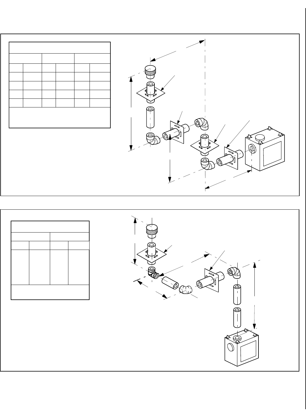
Vertical (Offset) Installation
Analyze the vent routing and determine the
number of vent sections and elbows required.
Refer to Vertical Vent Figures and Tables on
page 14 and 15 to select the type of vertical
installation desired. Vent sections are available
in net lengths of 4 ¹⁄₂" (114 mm), 10 ¹⁄₂" (267
mm), 22 ¹⁄₂" (572 mm), 34 ¹⁄₂" (876 mm) and 46
¹⁄₂" (1181 mm). Refer to the Vent Section
Length Chart on page 11 for an aid in selecting
length combinations. Elbows are available in
45° and 90° configurations. Refer to
Figure 27
for the SV4.5E45 and SV4.5E90 elbow dimen-
sional specifications.
Where required, a telescopic vent section
(SV4.5LA) may be used to provide the installer
with an option in installing in tight and con-
fined spaces or where the vent run made up of
fixed length pieces develops a joint in a unde-
sirable location, or will not build up to the
required length. The SV4.5LA Telescopic Vent
Section has an effective length of from 1 ¹⁄₂" (38
mm) to 7 ¹⁄₂" (191 mm). The SV4.5LA is fitted
with a locking inclined channel end (identical to
a normal vent section component) and a plain
end with 3 pilot holes. Slip the plain end over
the locking channel end of a standard SV4.5
vent component the required distance and se-
cure with three screws.
Maintain a minimum 1" (25 mm) clearance to
combustible materials for all vertical elements.
Clearances for all horizontal elements are 3"
(76 mm) on top, 1" (25 mm) on sides and 1"
(25 mm) on the bottom.
A. Frame ceiling opening - Use a plumb
line from the ceiling above the appliance to
locate center of the vertical run. Cut and/or
frame an opening, 10¹⁄₂" x 10¹⁄₂" (267mm x
267mm) inside dimensions, about this cen-
ter mark
(Figure 22)
.
To attach a vent component to the appliance
collar, align the dimpled end over the collar,
adjusting the radial alignment until the four lock-
ing dimples are aligned with the inlet of the four
inclined channels on the collar (
refer to Figure
23)
. Push the vent component against the collar
until it fully engages, then twist the component
clockwise, running the dimples down and along
the incline channels until they seat at the end of the
channels. The unitized design of the Secure
Vent components will engage and seal both
the inner and outer pipe without the need for
sealant or screws. If desired, a #6 x ¹⁄₂" screw
may be used at the joint, but is not required as
the pipe will securely lock when twisted.
C. Attach vent components to each other - Other
vent sections may be added to the previously
installed section in accordance with the require-
ments of the vertical vent figures and tables. To
add another vent component to a length of vent
run, align the dimpled end over the inclined
channel end of the previously installed section,
adjusting the radial alignment until the four
locking dimples are aligned with the inlets of the
four incline channels of the previous section.
Push the vent component against the previous
section until it fully engages, then twist the
component clockwise running the dimples down
and along the incline channels until they seat at
the end of the channels.
E. Support the vertical vent run sections -
Note - Proper venting support is very impor-
tant. The weight of the vent must not be sup-
ported by the firplace in any degree.
Support the vertical portion of the venting sys-
tem every 8 feet (2.4m) above the fireplace vent
outlet. One method of support is by utilizing
field provided support straps (conventional
plumber's tape). Secure the plumber's tape to
the framing members with nails or screws.
Loop the tape around the vent, securing the
ends of the tape to the framing. If desired,
sheet metal screws #6 x ¹⁄₂" length may be
used to secure the support straps to the vent
pipe. See
Figure 25.
Another method, where the vent is not adjacent
to a wall, is illustrated in
Figure 26
. Here, support
straps (96K93) and support plates (96K92) can
be used to support the weight of the vent.
B. Attach vent components to appliance - Se-
cure Vent SV4.5 direct vent system components
are unitized concentric pipe components featur-
ing positive twist lock connections (
see Figure
23
). All of the appliances covered in this docu-
ment are fitted with collars having locking in-
clined channels.
The dimpled end of the vent components fit over
the appliance collar to create the positive twist
lock connection.
13
NOTE: DIAGRAMS & ILLUSTRATIONS NOT TO SCALE.
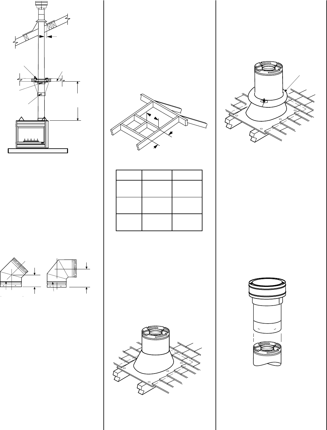
Framing Dimensions for Roof
Pitch C D
0/12 10¹⁄₂ in. 10¹⁄₂ in.
(267 mm) (267 mm)
6/12 10¹⁄₂ in. 12 in.
(267 mm) (305 mm)
12/12 10¹⁄₂ in. 17 ³⁄₄ in.
(267 mm) (451 mm)
C
D
Storm
Collar
8 feet (2.4 m)
Maximum
SV4.5CGV-1
Termination
SV4.5FA OR
SV4.5FB Flashing
AND SV4.5SC
STORM COLLAR
**SV4.5VF
Firestop/Spacer
1" (25.4 mm)
Minimum Clearance
to Combustibles
*SV4.5SU
Support Strap
SV4.5SP
*Support Plate
*Secured to Vent
With Appropriate
Fasteners
Ceiling
Framing
**When using Secure Flex,
use Firestop/Spacer
SF4.5VF
SV4.5E90
(90° Elbow)
7 ⁵⁄₈"
(194 mm)
Swivel Joint
(360
°
swivel)
4 ¹³⁄₁₆"
(122 mm)
SV4.5E45
(45° Elbow)
Swivel Joint
(360
°
swivel)
Figure 28
Figure 29
Figure 31
Figure 30
If the vent system extends more than 5' (1.5 m)
above the roof flashing, stabilizers may be nec-
essary. Additional screws may be used at sec-
tion joints for added stability. Guide wires may
be attached to the joint for additional support on
multiple joint configurations.
G. Continue installation of horizontal/inclined
sections - Continue with the installation of the
straight vent sections in horizontal/inclined run
as described in Step C. Install support straps
every 5 ft. (1.52 m) along horizontal/inclined
vent runs using conventional plumber’s tape.
See page 16, Figure 37.
It is very important
that the horizontal/inclined run be maintained
in a straight (no dips) and recommended to be
in a slightly elevated plane, in a direction
away from the fireplace of ¹⁄₄" rise per foot (20
mm per meter) which is ideal, though rise per
foot run ratios that are smaller are acceptable all
the way down to at or near level.
Figure 27
F. Change vent direction to horizontal/in-
clined run - At transition from or to a horizon-
tal/inclined run, install the SV4.5E45 and
SV4.5E90 elbows in the same manner as the
straight vent sections. The elbows feature a
twist section to allow them to be routed about
the center axis of their initial collar section to
align with the required direction of the next vent
run element. Twist elbow sections in a clock-
wise direction only so as to avoid the possiblity
of unlocking any of the previously connected
vent sections. See
Figure 27
.
Use a carpenter’s level to measure from a
constant surface and adjust the support straps
as necessary.
It is important to maintain the required clear-
ances to combustibles: 1" (25 mm) at all
sides for all vertical runs; and 3" (76 mm) at
the top, 1" (25 mm) at sides, and 1" (25 mm)
at the bottom for all horizontal/inclined runs.
K. Install the vertical termination - The final step
involves installation of the SV4.5CGV-1 Vertical
Termination. Extend the vent sections to the
height as shown in the "Vertical vent termination
section" on page 4. The SV4.5CGV-1 Vertical
Termination
(Figure 31)
can be installed in the
exact same fashion as any other Secure Vent
section. Align the termination over the end of the
previously installed section, adjusting the radial
alignment until the four locking dimples of the
termination are aligned with the inlets of the four
incline channels of the last vent section. Push the
termination down until it fully engages, then twist
the termination clockwise running the dimples
down and along the incline channels until they are
seated at the end of the channels.
I. Install the roof flashing - Extend the vent
sections through the roof structure. Install the
roof flashing over the vent section and posi-
tion such that the vent column rises vertically
(use carpenters level) (
Figure 29
). Nail along
perimeter to secure flashing or adjust roofing
to overlap the flashing edges at top and sides
only and trim where necessary. Seal the top
and both sides of the flashing with waterproof
caulking.
H. Frame roof opening - Identify location for
vent at the roof. Cut and/or frame opening per
Roof Framing Chart and
Figure 28
.
J. Install the storm collar - Install the storm
collar, supplied with the flashing, over the vent/
flashing joint. See
Figure 30.
Loosen the storm
collar screw. Slide collar down until it meets the
top of the flashing. Tighten the adjusting screw.
Apply non-combustible caulking or mastic
around the circumference of the joint to provide
a water tight seal.
Figure 26
14 NOTE: DIAGRAMS & ILLUSTRATIONS NOT TO SCALE.
40 feet (12.2 meters)
Maximum
*Ceiling
Firestop/Spacer
(SV4.5VF)
A Vent Restrictor, as
shown in Figure 19,
page 10, must be used
in this application
*When using Secure Flex,
use Firestop/Spacer
SF4.5VF
AELBAT
VM
MUMINI
mumixaMH
teef)m(teef)m(
1)503.0(2)16.0(
2)16.0(4 )222.1(
3)419.0(6)68.1(
4)22.1(8)4.2(
.xaM)m4.21(teef04=H+V .xaM)m4.2(teef8=H
BELBAT
VM
MUMINI
HmumixaM
teef)sretem(teef)sretem(
1*)503.0(5)25.1(
2)016.0(01)1.3(
3)419.0(51)56.4(
4)22.1(02)2.6(
V+V
1
.xaM)m4.21(teef04=H+
H.xaM)m2.6(teef02=
V
H
*Ceiling
Firestop/Spacer
(SV4.5VF)
**Wall
Firestop/Spacer
(SV4.5HF)
A Vent Restrictor, as
shown in Figure 20,
page 10, must be used
in this application
*When using Secure Flex,
use Firestop/Spacer
SF4.5VF
**When using Secure
Flex, use Firestop/Spacer
SF4.5HF
H
V
V1
*Ceiling
Firestop/Spacer
(SV4.5VF)
**Wall
Firestop/Spacer
(SV4.5HF) A Vent Restrictor, as
shown in Figure 19,
page 10, must be used
in this application
**When using Secure
Flex, use Firestop/Spacer
SF4.5HF
*When using Secure Flex,
use Firestop/Spacer
SF4.5VF
Figure 33
-
Rear Vent - ONE 90 DEGREE ELBOW
Figure 32
- Top Vent - STRAIGHT
Figure 34
-
Top Vent - TWO 90 DEGREE ELBOWS
*When developing chimney systems
with horizontal runs (H) that end with
a vertical run (V1), it is allowable to
use an elbow attached directly to the
top collar. Count the elbow attached
to the collar as 1 foot of (V) run.
VERTICAL VENT FIGURES/TABLES
Note: SV4.5VF (Secure Vent), SF4.5VF (Secure
Flex) firestop/spacer must be used anytime vent
pipe passes through a combustible floor or ceil-
ing. SV4.5HF (Secure Vent), SF4.5HF (Secure
Flex)firestop/spacer must be used anytime vent
pipe passes through a combustible wall.
Note: Two 45 degree elbows may be used in
place of one 90 degree elbow. The same rise to
run ratios, as shown in the venting figures for 90
elbows, must be followed if 45 degree elbows are
used.
Note: It is very important that the horizontal/
inclined run be maintained in a straight (no
dips) and recommended to be in a slightly
elevated plane, in a direction away from the
fireplace of
¹⁄₄
" rise per foot (20 mm per
meter) which is ideal, though rise per foot run
ratios that are smaller are acceptable all the
way down to at or near level.
Note: Secure Vent (rigid vent pipe) is shown
in the figures; Secure Flex (flexible vent pipe)
may also be used (see page 21).
WARNING: UNDER NO CIRCUM-
STANCES MAY SEPARATE SECTIONS
OF CONCENTRIC FLEXIBLE VENT
PIPE BE JOINED TOGETHER.
15
NOTE: DIAGRAMS & ILLUSTRATIONS NOT TO SCALE.
CELBAT
muminiMVmumixaMHH+H
1
mumixaM
teef)m(teef)m(teef)m(
1)503.0(2)016.0(5)25.1(
2)016.0(4)22.1(01)1.3(
3)419.0(6)68.1(51)56.4(
4)22.1(8)84.2(02)2.6(
V+V
1
H+H+
1
.xaM)m4.21(teef04= .xaM)m84.2(teef8=HH+H
1
.xaM)m2.6(teef02=
DELBAT
VM MUMINI HH+
1
mumixaM
teef)m(teef)m(
1)503.0(5)25.1(
2)016.0(01)1.3(
3)419.0(51)56.4(
4)22.1(02)2.6(
H+H
1
.xaM)m2.6(teef02=
V+V
1
H+H+
1
.xaM)m4.21(teef04=
H1
V
V1
H
*Ceiling
Firestop/Spacer
(SV4.5VF)
**Wall
Firestop/Spacer
(SV4.5HF)
*Ceiling
Firestop/Spacer
(SV4.5VF)
A Vent Restrictor, as
shown in Figure 20,
page 10, may be used in
this application
*When using Secure Flex,
use Firestop/Spacer
SF4.5VF
**When using Secure
Flex, use Firestop/Spacer
SF4.5HF
**Wall
Firestop/Spacer
(SV4.5HF)
V
H1
H
*Ceiling
Firestop/Spacer
(SV4.5VF)
V1**Wall
Firestop/Spacer
(SV4.5HF)
A Vent Restrictor, as
shown in Figure 19,
page 10, may be used in
this application
*When using Secure Flex,
use Firestop/Spacer
SF4.5VF
**When using Secure
Flex, use Firestop/Spacer
SF4.5HF
Figure 35
- Rear Vent - THREE ELBOWS
Figure 36-
Top Vent - THREE ELBOWS
VERTICAL VENT FIGURES/TABLES
(continued)
16 NOTE: DIAGRAMS & ILLUSTRATIONS NOT TO SCALE.
Vertical
Rise
SV4.5E90
Elbow
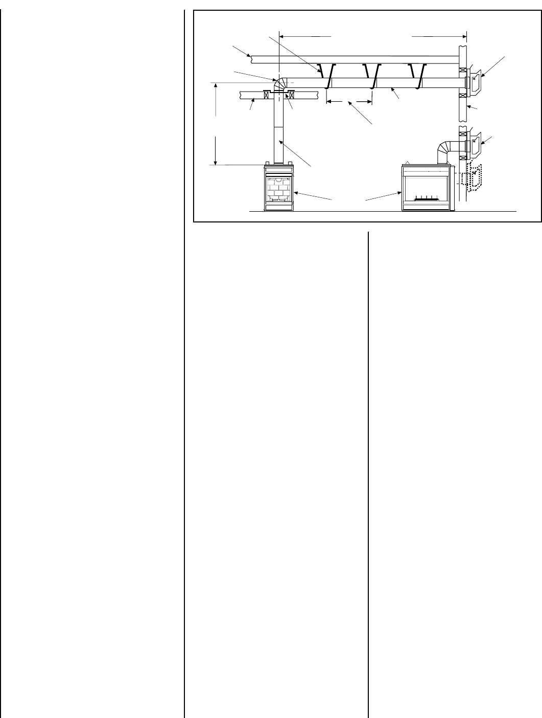
Horizontal / Inclined Run SV4.5 HT
Termination
*Firestop/Spacer
SV4.5VF
SV4.5L6/12/24/36/48
Vent Sections
Support Bracket Spacing
Every 5 ft (1.52 m)
See Figure 25 on page 12
or Figure 26 on page 13
for vertical vent section
support.
Support
Brackets
Building
Support
Framing
Ceiling
Fireplace
Exterior
Wall
TYPICAL HORIZONTAL VENT INSTALLATION
*When using Secure Flex,
use Firestop/Spacer
SF4.5VF
SV4.5 HTS
Termination
Figure 37
Push the vent component against the collar
until it fully engages, then twist the compo-
nent clockwise, running the dimples down and
along the incline channels until they seat at the
end of the channels. The unitized design of the
Secure Vent components will engage and seal
both the inner and outer pipe elements with
the same procedure. Sealant and securing
screws are not required.
E. Attach vent components to each other -
Other vent sections may be added to the previ-
ously installed section in accordance with the
requirements of the vent tables. To add another
vent component to a length of vent run, align
the dimpled end of the component over the
inclined channel end of the previously installed
section, adjusting the radial alignment until the
four locking dimples are aligned with the inlets
of the four incline channels of the previous
section. Push the vent component against the
previous section until it fully engages, then
twist the component clockwise running the
dimples down and along the incline channels
until they seat at the end of the channels.This
seating position is indicated by the alignment
of the arrow and dimple as shown in
Figure 24
on page 12.
F. Install firestop/spacer at ceiling -
When using Secure Vent, use SV4.5VF fir-
estop/spacer at ceiling joists; when using Se-
cure Flex, use SF4.5VF firestop/spacer. If there
is living space above the ceiling level, the fir-
estop/ spacer must be installed on the bottom
side of the ceiling. If attic space is above the
ceiling, the firestop/ spacer must be installed on
the top side of the joist. Route the vent sections
through the framed opening and secure the
firestop/spacer with 8d nails or other appropriate
fasteners at each corner.
Remember to maintain 1" (25 mm) clearance
to combustibles, framing members, and at-
tic or ceiling insulation when running verti-
cal chimney sections. Attic insulation shield
(96K94) may be used to obtain the required
clearances indicated here. See installation
accessories table on page 27.
HORIZONTAL (OUTSIDE WALL)
TERMINATION SYSTEM
Secure Vent SV4.5 direct vent system compo-
nents are unitized concentric pipe compo-
nents featuring positive twist lock connection,
(
refer to Figure 23
on page 12). All of the
appliances covered in this document are fitted
with collars having locking inclined channels.
The dimpled end of the vent components fit
over the appliance collar to create the positive
twist lock connection.
A. Plan the vent run -
Analyze the vent routing and determine the
types and quantities of sections required
4 ¹⁄₂" (114 mm), 10 ¹⁄₂" (267 mm), 22 ¹⁄₂" (572
mm), 34 ¹⁄₂" (876 mm) and 46 ¹⁄₂" (1181 mm)
net section lengths are available. Make allow-
ances for elbows as indicated in
Figure 27 on
page 13
.
Maintain a minimum 1" (25 mm) clearance to
combustibles on the vertical sections. Clearances
for the horizontal runs are; 3" (76 mm) on top, 1"
(25 mm) on sides, and 1" (25 mm) at the bottom.
B. Frame exterior wall opening -
Locate the center of the vent outlet on the exterior
wall according to the dimensions shown in
Figures
9 (CDST), 10 (CDPF), 11 (CDCL), or 12 (CDCR)
on
page 7. Cut and/or frame an opening, 10¹⁄₂" x 12¹⁄₈"
(267 mm x 308mm) inside dimensions, about this
center.
C. Frame ceiling opening - If the vertical
route is to penetrate a ceiling, use plumb line
to locate the center above the appliance. Cut
and/or frame an opening, 10¹⁄₂" x 10¹⁄₂" (267
mm x 267 mm) inside dimensions, about this
center (refer to
Figure 22
on page 12 ).
G. Support the vertical run sections -
See section E on page 12.
H. Change vent direction - At transition from
or to a horizontal/inclined run, install the SV4.5E45
and SV4.5E90 elbows in the same manner as the
straight vent sections. The elbows feature a twist
section to allow them to be routed about the
center axis of their initial collar section to align
with the required direction of the next vent run
element. Twist elbow sections in a clockwise
direction only so as to avoid the possiblity of
unlocking any of the previously connected
vent sections.See
Figure 27 on page 12
.
D. Attach vent components to appliance - To
attach a vent component to the appliance collar,
align the dimpled end over the collar, adjusting the
radial alignment until the four locking dimples are
aligned with the inlets of the four incline channels
on the collar (
refer to Figure 23
on page 12).
I. Continue installation of horizontal/inclined
sections - Continue with the installation of the
straight vent sections in horizontal/inclined
run as described in Step E. Install support
straps every 5 ft. (1.52 m) along horizontal/
inclined vent runs using conventional plumber’s
tape. See
Figure 37.
It is very important that
the horizontal/inclined run be maintained in a
straight (no dips) and recommended to be in
a slightly elevated plane, in a direction away
from the fireplace of
¹⁄₄" rise per foot (20 mm
per meter) which is ideal, though rise per foot
run ratios that are smaller are acceptable all the
way down to at or near level. Use a carpenter’s
level to measure from a constant surface and
adjust the support straps as necessary.
It is important to maintain the required clear-
ances to combustibles: 1" (25 mm) at all sides
for all vertical runs; and 3" (76 mm) at the top,
1" (25 mm) at sides, and 1" (25 mm) at the
bottom for all horizontal/inclined runs
Both of these horizontal vent systems terminate
through an outside wall. Building Codes limit or
prohibit terminating in specific areas. Refer to
Figure 8
on page 6 for location guidelines.
Figure 37, and Figures 40 to 46 on page 18 to
20
and their associated Horizontal Vent Table
illustrate the horizontal venting configurations
that are allowed to be used with these appliances.
Secure Vent pipe applications are shown in these
figures; Secure Flex pipe may also be used.
See
page 21.
A Horizontal Vent Table summarizes
each system’s minimum and maximum vertical
and horizontal length values that can be used to
design and install the vent components in a
variety of applications.
17
NOTE: DIAGRAMS & ILLUSTRATIONS NOT TO SCALE.
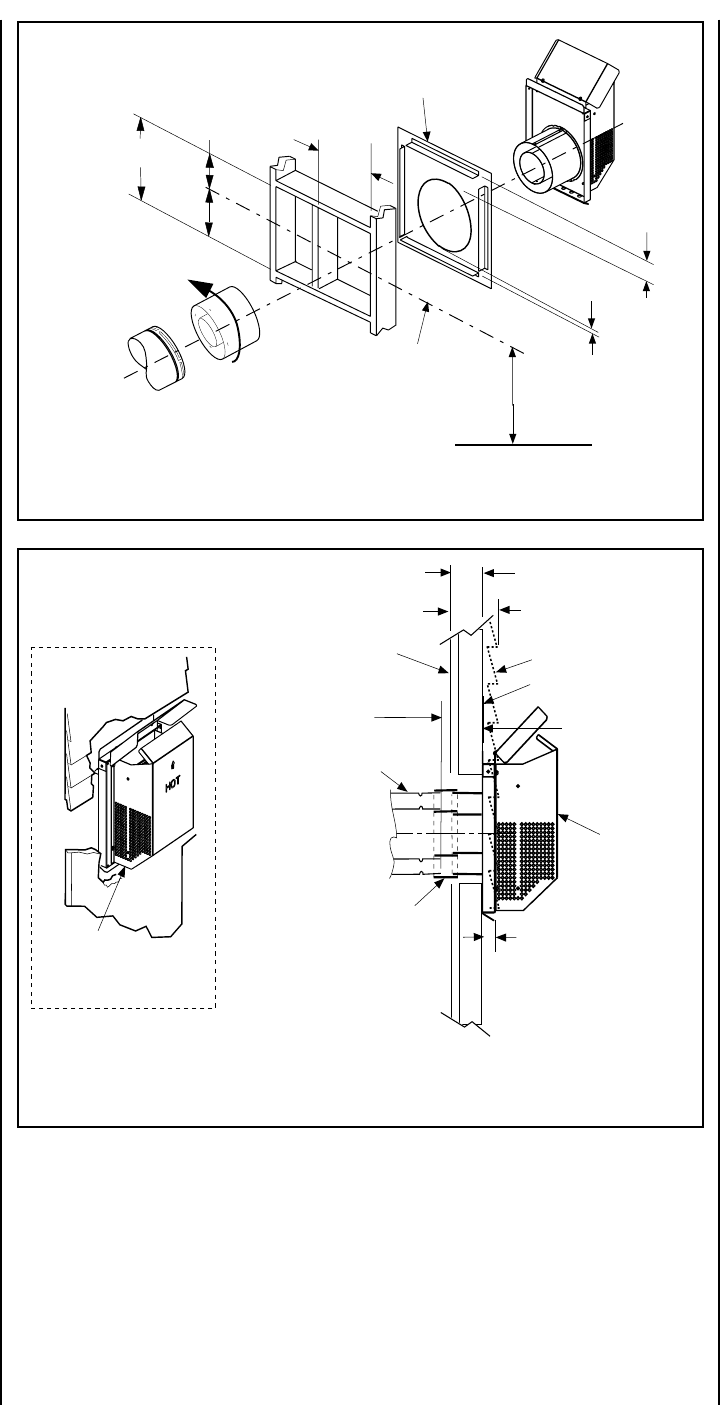
M. Install the termination -
J. Assemble vent run to exterior wall - If not
previously measured, locate the center of the
vent at the exterior wall. Prepare an opening as
described in Step B. Assemble the vent system
to point where the terminus of the last section is
within 7¹⁄₂ in. (191 mm) to 11³⁄₄ in. (298 mm)
inboard of the exterior surface to which the
SV4.5HT termination is to be attached, see
Fig-
ure 39
. If the terminus of the last section is not
within this distance, use the telescopic vent
section SV4.5LA, as the last vent section. For
wall thicknesses greater than that shown in
Figure 38
, refer to
Table 3 on page 18
. This table
lists the additional venting components needed
(in addition to the termination and adapter) for a
particular range of wall thicknesses.
K. Attach termination adapter - Attach the
adapter (adapter - SV4.5RCH - provided with
the termination) to the vent section or tele-
scoping vent section), elbow or appliance col-
lar as shown in
Figure 38
in the same manner
as any SV4.5 vent component (refer to Step E).
L. Install Firestop/Spacer at exterior wall -
When using the square termination, install
SV4.5HF (Secure Vent), SF4.5HF (Secure Flex)
Firestop/Spacer over the opening at the exte-
rior side of the framing, long side up, with the
3 inch spacer clearance at the top as shown in
Figure 38
, and nail into place.
(The Firestop/Spacer may also be installed over
the opening at the interior side of the framing.)
When using the round termination, a separate
firestop/spacer is not required since this ter-
mination has integral spacers which provide
the same function as a separate firestop/spacer.
Install the square termination (SV4.5HT)- For
the last step , from outside the exterior wall,
slide the collars of the termination onto the
adapter until the termination seats against the
exterior wall surface to which it will be attached.
Orient the housing of the termination with the
arrow pointed upwards. Secure the termina-
tion to the exterior wall. The horizontal termi-
nation must not be recessed into the exterior
wall or siding by more than the 1 ¹⁄₄" (32 mm)
as shown in
Figure 39
.
SFHRK Snorkel Cap –The snorkel cap is de-
signed to be fitted into a basement window box.
The SFHRK cap is for use with flex vent pipe.
Vertical distance between the inlet and outlet of
the cap is 28 in. (711 mm).
*1¹⁄₄" Maximum Recess of
Square Termination into
Exterior Finishing Material
Exterior Surface of
Framing
7¹₂ in. (191 mm) to
11³₄ in. (298 mm)
Exterior Surface of Siding
Minimum wall thickness
*5 in. (127 mm)
Interior Surface of
Finished Wall
Maximum wall thickness
11³₄ in. (298 mm)
Maximum Extent of
Vent Run Sections
Relative to Exterior
Surface of Framing
Last Vent Section. Use
Telescopic Vent
Section (SV4.5LA), If
Necessary
Adapter
SV4.5RCH
SV4.5HT
Square
Termination
*Cut termination collar for wall
thicknesses less than 7¹₂ in. (191 mm)
Note - Firestop/Spacer (SV4.5HF)
required but not shown for clarity.
Note - When using Secure Flex,
use Firestop/Spacer SF4.5HF
Siding
Stucco
SV4.5HT
Square Termination
Stucco and Siding
Installation shown
Figure 38
Figure 39
Installing the Square Horizontal Termination (SV4.5HT)
Venting Connection and Exterior Wall Recessing of the
Square Horizontal Termination (SV4.5HT)
*When using Secure Flex, use
Firestop/Spacer SF4.5HF
Firestop/Spacer (SV4.5HF) shown
on the exterior side of the wall. It
may also be installed on the
interior side.
10¹⁄₂"
(267 mm)
7"
(178)
5¹⁄₈"
(130 mm)
12¹⁄₈"
(308 mm)
Note: Centerline of Vent Piping
is NOT the Same as the
Centerline of the Framed
Opening.
6 to 48 inch Vent Section,
Telescopic vent section,
Elbow or Appliance Collar
See Figure 9 (CDST), 10
(CDPF), 11 (CDCL) or 12
(CDCR) on page 7 for Min.
Distance to Base of Appliance.
Base of Appliance
3"
(76 mm)
1"
(25.4 mm)
Adapter
SV4.5RCH
SV4.5HT
Termination
18 NOTE: DIAGRAMS & ILLUSTRATIONS NOT TO SCALE.
EELBAT
wobleeerged09en0=V .xaM)m419.0(teef3=H
ELBATF
muminiMVmumixaMH
teef)m(teef)m(
1)503.0(5)25.1(
2)16.0(01)1.3(
3)419.0(51)56.4(
4)22.1(02)2.6(
.xaM)m4.21(teef04=H+V .xaM)m2.6(teef02=H
*When using Secure Flex, use
Firestop/Spacer SF4.5HF
*Wall Firestop/Spacer
(SV4.5HF)
H = 28 in. (711 mm)
Maximum
7 in. (711 mm)
21 in. (533 mm)
Maximum
H
V
*Wall Firestop/Spacer
(SV4.5HF)
*When using Secure Flex, use
Firestop/Spacer SF4.5HF
H
V
**Wall Firestop/Spacer
(SV4.5HF)
*Ceiling
Firestop/Spacer
(SV4.5VF)
*When using Secure Flex,
use Firestop/Spacer
SF4.5VF
**When using Secure Flex,
use Firestop/Spacer
SF4.5HF
Figure 40
- Rear Vent - NO ELBOWS
Figure 41
-
Top Vent -
ONE 90 DEGREE ELBOW - ELBOW CONNECTION AT APPLIANCE
Figure 42
-
Top Vent - ONE 90 DEGREE ELBOW - ELBOW
CONNECTION NOT DIRECTLY AT APPLIANCE
Only the square termination (SV4.5HT) may be used.
HORIZONTAL VENT FIGURES/TABLES
Note: SV4.5VF (Secure Vent), SF4.5VF (Secure Flex) firestop/spacer must be
used anytime vent pipe passes through a combustible floor or ceiling.
SV4.5HF (Secure Vent), SF4.5HF (Secure Flex) firestop/spacer must be used
anytime vent pipe passes through a combustible wall.
Note: Two 45 degree elbows may be used in place of one 90 degree elbow.
The same rise to run ratios, as shown in the venting figures for 90 elbows,
must be followed if 45 degree elbows are used.
Square termination (SV4.5HT) shown.
Square termination (SV4.5HT) shown.
Note: It is very important that the horizontal/inclined run be maintained
in a straight (no dips) and recommended to be in a slightly elevated
plane, in a direction away from the fireplace of
¹⁄₄
" rise per foot (20 mm
per meter) which is ideal, though rise per foot run ratios that are smaller
are acceptable all the way down to at or near level.
*Note: See Figure 39 for wall thickness range reductions when using
SV4.5HT termination.
Note: Secure Vent components (rigid vent pipe and terminal) are shown
in the figures; Secure Flex components (flexible vent pipe and terminal) may
also be used.
See
Table 3
as an aid in venting component selection for a particular
range of exterior wall thicknesses.
WARNING: UNDER NO CIRCUMSTANCES MAY SEPARATE
SECTIONS OF CONCENTRIC FLEXIBLE VENT PIPE BE JOINED
TOGETHER.
suoiraVrofderiuqeRstnenopmoCgnitneV-3ELBAT ehTgnisUnehW,sessenkcihTllaWroiretxE )TH5.4VS(noitanimreTerauqS
deriuqeRstnenopmoCgnitneV sessenkcihTllaWroiretxE mm(sehcni )
ylnOtiKnoitanimreT2/171ot4/31)892ot191(
tnev.ni6dnatiKnoitanimreT )6L5.4VS(noitces 14/31)914ot892(2/161ot
tnev.ni21dnatiKnoitanimreT )21L5.4VS(noitces ot464(4/122*ot4/181 )565*
cipocseleTdnatiKnoitanimreT .ni6dna)AL5.4VS(noitces )6L5.4VS(noitcestnev 31)195*ot033(4/132*ot
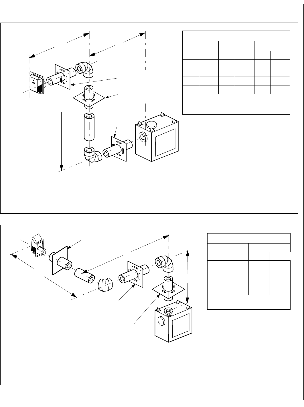
19
NOTE: DIAGRAMS & ILLUSTRATIONS NOT TO SCALE.
H1
V
H
**Wall Firestop/Spacer
(SV4.5HF)
*Ceiling
Firestop/Spacer
(SV4.5VF)
*When using Secure Flex,
use Firestop/Spacer
SF4.5VF
**When using Secure
Flex, use Firestop/Spacer
SF4.5HF
**Wall
Firestop/Spacer
(SV4.5HF)
GELBAT
muminiMVmumixaMHH+H
1
mumixaM
teef)m(teef)m(teef)m(
1)503.0(2)016.0(5)25.1(
2)016.0(4)22.1(01)1.3(
3)419.0(6)68.1(51)56.4(
4)22.1(8)84.2(02)2.6(
H+H+V
1
.xaM)m4.21(teef04= .xaM)m84.2(teef8=HH+H
1
.xaM)m2.6(teef02=
HELBAT
VM MUMINI H+H
1
mumixaM
teef)m(teef)m(
1)503.0(5)25.1(
2)016.0(01)1.3(
3)419.0(51)56.4(
4)22.1(02)2.6(
H+H+V
1
.xaM)m4.21(teef04=
H+H
1
.xaM)m2.6(teef02=
V
H
H1
**Wall Firestop/Spacer
(SV4.5HF)
**Wall Firestop/Spacer
(SV4.5HF)
*Ceiling Firestop/Spacer
(SV4.5VF)
*When using Secure Flex,
use Firestop/Spacer
SF4.5VF
**When using Secure
Flex, use Firestop/Spacer
SF4.5HF
Figure 43
-
Rear Vent - TWO 90 DEGREE ELBOWS
Figure 44
-
Top Vent - TWO 90 DEGREE ELBOWS
HORIZONTAL VENT FIGURES/TABLES
(continued)
Square termination (SV4.5HT) shown.
See
Table 3
as an aid in venting component selection for a particular range of exterior wall thicknesses.
See
Table 3
as an aid in venting component selection for a particular range of exterior wall thicknesses.
Square termination (SV4.5HT) shown.
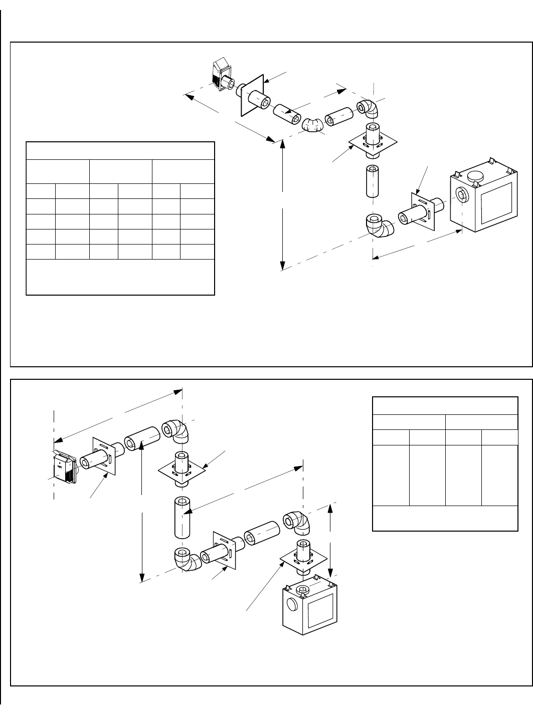
20 NOTE: DIAGRAMS & ILLUSTRATIONS NOT TO SCALE.
HORIZONTAL VENT FIGURES/TABLES
(continued)
V
H2
H1
H
*Ceiling Firestop/Spacer
(SV4.5VF)
**Wall Firestop/Spacer
(SV4.5HF)
*When using Secure Flex,
use Firestop/Spacer
SF4.5VF
**When using Secure
Flex, use Firestop/Spacer
SF4.5HF
**Wall Firestop/Spacer
(SV4.5HF)
JELBAT
muminiMVmumixaMH H+H
1
H+
2
mumixaM
teef)m(teef)m(teef)m(
1)503.0(2)016.0(5)25.1(
2)016.0(4)22.1(01)1.3(
3)419.0(6)68.1(51)56.4(
4)22.1(8)84.2(02)2.6(
H+H+V
1
H+
2
.xaM)m4.21(teef04= .xaM)m84.2(teef8=H
H+H
1
H+
2
.xaM)m2.6(teef02=
KELBAT
VM MUMINI HmumixaM
teef)m(teef)m(
1)503.0(5)25.1(
2)016.0(01)1.3(
3)419.0(51)56.4(
4)22.1(02)2.6(
H+H
1
.xaM)m2.6(teef02=
V+V
1
H+H+
1
.xaM)m4.21(teef04=
V
H
H1
V1
**Wall
Firestop/spacer
(SV4.5HF)
*Ceiling Firestop/spacer
(SV4.5VF)
**Wall
Firestop/spacer
(SV4.5HF)
*When using Secure Flex,
use Firestop/Spacer
SF4.5VF
**When using Secure
Flex, use Firestop/Spacer
SF4.5HF
*Ceiling Firestop/spacer
(SV4.5VF)
Figure 46
-
Top Vent - THREE 90 DEGREE ELBOWS
Figure 45
- Rear Vent - THREE 90 DEGREE ELBOWS
Square termination (SV4.5HT) shown.
Square termination (SV4.5HT) shown.
See
Table 3
as an aid in venting component selection for a particular range of exterior wall thicknesses.
See
Table 3
as an aid in venting component selection for a particular
range of exterior wall thicknesses.
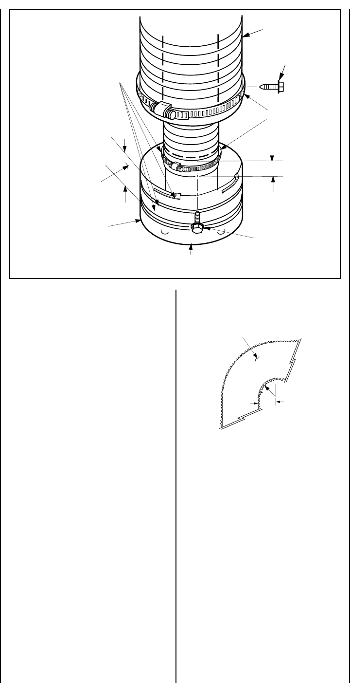
21
NOTE: DIAGRAMS & ILLUSTRATIONS NOT TO SCALE.
See the appropriate sections and figures
shown throughout the venting section for
their installation requirements.
GEAR
CLAMPS
Adapter
(SV4.5RF)
Apply ONLY MIL-PAC BLACK HIGH
TEMPERATURE SEALANT (Catalog No.
10K81) to the outside surface of both
collars of the adapter (be especially
careful to fill the grooves of the outer
collar to be covered by the flexible
pipe) and slide flexible pipe over
inner and outer adapter collars.
NOTE: OUTER PIPE IS PULLED AWAY TO
SHOW THE DETAIL OF THE INNER PIPE
FLEX VENT
1³⁄₄ in. (44 mm)
Flexible Pipe and
Adapter Outer
Collar Overlap 1³⁄₄ in. (44 mm)
Flexible Pipe and
Adapter Inner
Collar Overlap
SECURING SCREW
(3 PLACES EQUIDISTANT
JUST BELOW GEAR CLAMP)
Attach Adapter to Appliance
Collar, or Secure Vent Sections
SECURING SCREW
(3 PLACES EQUIDISTANT
JUST BELOW GEAR CLAMP)
5" (127 mm)
Radius Minimum
Flexible Vent Section
Figure 48
Figure 47
VERTICAL OR HORIZONTAL VENTING USING
SECURE FLEX
KITS AND COMPONENTS
Secure Flex venting kits and components may be
used in any venting application in place of rigid
Secure Vent (SV4.5) direct vent components. All
restrictions, clearances and allowances that per-
tain to the rigid piping apply to the flexible venting.
Secure Flex
kits may not be modified; also,
under no circumstances may separate sections
of flex pipe be joined together.
Using adapter (SV4.5RF), Secure Flex kits
may be added to the end of a vent run made up
of rigid Secure Vent (SV4.5) vent sections
provided that doing so does not violate any of
the venting length, height, routing, horizontal
to vertical ratio requirements or clearance
considerations detailed in this manual.
Secure Flex kits come with an adapter that can
be fitted to the inclined channel end of the last
Secure Vent (SV4.5) vent section in a rigid
system in the exact same fashion as any other
Secure Vent section.
Align the dimpled end of the adapter over the
previously installed section or appliance col-
lar, adjusting the radial alignment until the four
locking dimples of the adapter are aligned with
the inlets of the four incline channels of the last
vent section or collar. Push on the adapter
until it fully engages, then twist the adapter
clockwise running the dimples down and along
the incline channels until they seat at the end
of the channels.
2. Apply a bead of Mill-Pac Black (700°F) high
temperature sealant - Catalog No. 10K81) to
the outer adapter collar; to the grooves of the
collar which extend approximately 1 inch from
the end and to the flat surface, approximately 1³⁄₈
inches from the end.
3. Pull and extend the outer flexible vent pipe.
4. Slide the outer flex pipe over the adapter
collar. Ensure the flexible vent pipe completely
engages the adapter collar to a distance of 1³⁄₄
inches from the end, and that it is free from
damage or tears.
5. Slide the gear clamp down and tighten it
fully to secure the flexible vent to the adapter
outer collar approximately ³⁄₄ inch from the
end of the flex.
6. Install three screws 120 degrees apart
through the flexible vent pipe and into the
adapter collar just below the gear clamp to
provide additional security to the connection.
C. Route Flex Vent -
Ensure that the flex vent is properly routed to
provide the required clearance. Do not allow
the flexible vent to bend in a radius tighter than
5" (127 mm). Refer to
Figure 48
. Space out the
internal flex vent spacers evenly - approxi-
mately every 6 inches - and avoid kinking of
inner pipe. Support horizontal sections of flex
with metal straps at 2 foot (0.61m) intervals.
D. Install Firestop/Spacers at ceilings and walls -
When Secure Flex penetrates a wall or ceil-
ing, a firestop/spacer is required: use the
SF4.5 VF firestop/spacer for ceilings and the
SF4.5 HF firestop/spacer for walls.
Attach the flexible vent to the adapter as
follows
(also see Figure 47 ):
A. Install the Inner Flex Pipe -
1. Install the small gear clamp loosely around
the inner flexible vent pipe, push it back out of
the way.
2. Apply a bead of Mill-Pac Black (700°F)
high temperature sealant - Catalog No.
10K81) to the inner adapter collar, approxi-
mately ¹⁄₂ inch from the end.
3. Pull and extend the inner flexible vent pipe.
4. Slide the inner flex pipe over the adapter
collar. Ensure the flexible vent pipe completely
engages the adapter collar to a distance of 1³⁄₄
inches from the end, and that it is free from
damage or tears.
5. Slide the gear clamp down and tighten it
fully to secure the flexible vent to the adapter
inner collar approximately ³⁄₄ inch from the
end of the flex.
6. Install three screws 120 degrees apart through
the flexible vent pipe and into the adapter collar
just below the gear clamp to provide additional
security to the connection.
B. Install the Outer Flex Pipe -
1. Install the large gear clamp loosely around
the outer flexible vent pipe, push it back out of
the way.
Note:
Secure Flex
vent must be attached to
Secure Flex
terminations only. DO NOT sub-
stitute
Secure Vent
terminations or the
Se-
cure Vent
adapter for
Secure Flex
compo-
nents. The collars of
Secure Flex
termina-
tions and adapters have a different diameter
than that used with the
Secure Vent
pipe.
Additionally,
Secure Flex
components have
an extended length center tube for use in
attaching the flexible vent.
E. Attach Flex Vent to Termination -
Secure Flex components can be purchased
separately and attached to bulk lengths of
Secure Flex flexible tubing cut to size at the
job site. Secure the flexible vent to the Secure
Flex terminations in the same manner (see
Figure 47 )
as it was attached to the adapter.
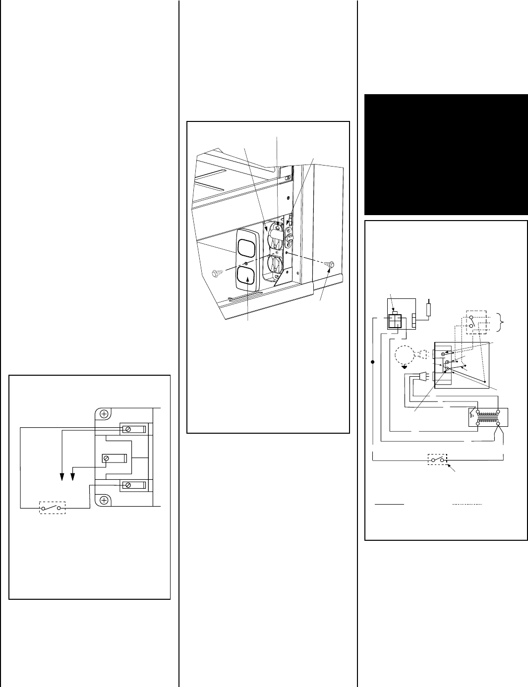
22 NOTE: DIAGRAMS & ILLUSTRATIONS NOT TO SCALE.
Step 4. FIELD WIRING
Refer to Section A for millivolt appliances and
Section B for electronic appliances. The gas
valve is set in place and pre-wired at the
factory on both models.
Note: The gas valve ON/OFF switch is shown in
Figure 51, or 52 on page 23. It is integral with
the gas valve and should be set to the ON
position.
A. Millivolt Wiring
(See Figure 49 )
–
1. Select any of the following optional con-
trols: appliance-mounted (rocker switch) or
wall-mounted switch, thermostat, or one of
the optional remote control kits. If appliance-
mounted ON/OFF control is selected mount it
in the gas valve mounting bracket.
2. If wall-mounted ON/OFF control or thermo-
stat is selected mount it in a convenient loca-
tion on a wall near the fireplace.
3. Wire the control switch within the millivolt
control circuit using the 15 feet of 2 conductor
wire supplied with the unit.
Caution: do not connect the optional wall
switch to a 120V power supply.
4. Alternatively, the appliance may be oper-
ated without the use of the controls indicated
in step 1, solely by manipulating the gas valve
control knob. In order to use this method,
twist the free ends of the two conductor wire
(located in the bottom compartment of the
unit) together as shown in
Figure 49
.
Note: The supplied 15 feet of 2 conductor wire
has one end of each conductor connected to the
gas valve circuit and the other end of each
conductor placed loose inside the bottom com-
partment of the unit.
Figure 49
10. After wiring is complete, reinstall the outlet
receptacle, junction box/outlet receptacle as-
sembly; install the field-provided the metal
junction box cover plate.
Receptacle, Junction Box and
Cover Plate Installation
Figure 50
2. Open the control compartment access panel by
actuating the spring-loaded magnetic catches se-
curing the panel, gently depressing the outer top
corners of the panel until the catches "pop" the panel
free, allowing it to swing out and down to open.
3. Remove the junction box/outlet receptacle
assembly by removing the securing screw at
the front right corner of the unit. See
Figure 50.
(The left and right designations used here are
reversed in CDCR applications.)
B. Electronic Wiring
(See either Figure 51, or 52 on page 23)
Note: The electronic appliance must be con-
nected to the main power supply.
1. Route a 3-wire 120Vac 60Hz 1ph power
supply to the appliance junction box.
4. Remove the outlet receptacle from the junc-
tion box by removing the two securing screws.
5. Install a field-provided strain relief in the
cabinet knockout opening for the protection of
the power supply wires.
6. Connect the power supply wires to the receptacle
as shown in
Figure 51, or 52 on page 23.
7. Connect the ground supply wire to the
green wire attached to the outlet receptacle's
green ground screw.
8. Install a wall-mounted ON/OFF switch or
thermostat (not supplied) in a convenient lo-
cation near the fireplace.
9. Wire the wall-mounted ON/OFF switch or
thermostat to the low voltage circuit as shown
in
Figure 51, or 52 on page 23.
Note: The supplied 15 feet of 2 conductor wire
has one end of each conductor connected to the
gas valve circuit and the other end of each
conductor placed loose inside the bottom com-
partment of the unit.
Step 5. WIRING - OPTIONAL FORCED
AIR BLOWER KIT
FBK-100, FBK-200 and FBK250 Kits
(See Figure 51 for FBK-100, FBK-200 and
Figure 52 on page 23 for FBK-250 wiring)
-
An electrical receptacle is provided for the
installation of the FBK-100, FBK-200 and
FBK-250 forced air blower kits. Electrical
power must be connected to this receptacle
in order to operate these blowers. Install the
blower kits according to the installation in-
structions provided with the kits.
Figure 51
Millivolt Wiring Diagram
If any of the original wire as supplied must be replaced,
it must be replaced with Type AWM 105°C, 18 GA. wire.
Thermopile
TH
TP TH
TP
*TWIST WIRES “A” AND “B” TOGETHER TO OPERATE UNIT
SOLELY BY MANIPULATING THE GAS VALVE CONTROL KNOB;
OR CONNECT WIRES TO OPTIONAL UNIT-MOUNTED ON/OFF
SWITCH OR WALL-MOUNTED ON/OFF SWITCH OR
THERMOSTAT TO OPERATE UNIT.
*UNIT-MOUNTED ON/OFF SWITCH (Accessory Option)
OR WALL-MOUNTED ON/OFF SWITCH (Accessory Option)
OR THERMOSTAT (Accessory Option)
OR REMOTE CONTROL RECEIVER (Accessory Option)
AB
1. If any of the original wire as supplied must be replaced,
1. it must be replaced with Type AWM 105°C – 18 GA. wire.
2. 120V, 60Hz – Less than 3 amps.
BK
Junction Box
Transf.
120 V.
24 V
Factory Wired Field Wired
BL
Electronic Wiring Diagram (Honeywell)
Showing the Blower Wiring for the Optional FBK-
100 and FBK-200 Kits
R
W
BL
OPT
BLOWER
G
W
*OPTIONAL
ACCESSORY
SWITCH
120
VAC.
BK
W
Gas Valve
B
R
IGNITER
PILOT
ASSEMBLY
Break Off
Tab
BK
G
*Blower speed control switch is provided in FBK200 blower kit.
Outlet Box
Green Ground
Screw
Hot side of Outlet
Schematic Representation Only
**ON/OFF Switch (Integral
with Gas Valve)
**Leave the ON/OFF switch, which is integral
with the gas valve, in the ON position.
OPTIONAL APPLIANCE-MOUNTED ON/OFF SWITCH
OR OPTIONAL WALL SWITCH OR OPTIONAL
THERMOSTAT OR OPTIONAL REMOTE RECEIVER
Red
pigtail
Black
pigtail
White Wire
to Opposite
Side
G
CDST, CDPF
AND CDCL OUTLET RECEPTACLE SHOWN.
CDCR HAS THE OUTLET RECEPTACLE LOCATED IN
THE LEFT CORNER OF THE UNIT
VIEW OF RIGHT BOTTOM CORNER OF UNIT
OUTLET RECEPTACLE
JUNCTION BOX
MOUNTING BRACKET
JUNCTION BOX
JUNCTION BOX
SECURING SCREW
FIELD-PROVIDED METAL JUNCTION BOX
COVER PLATE WITH SCREW
IMPORTANT: Ground supply lead must be
connected to the wire attached to the green
ground screw located on the outlet recep-
tacle. See
Figures 51, and 52 on page 23
.
Failure to do so will result in a potential safety
hazard. The appliance must be electrically
grounded in accordance with local codes or,
in the absence of local codes, the National
Electrical Code, ANSI/NFPA 70-(latest edi-
tion). (In Canada, the current CSA C22-1
Canadian Electrical Code.)
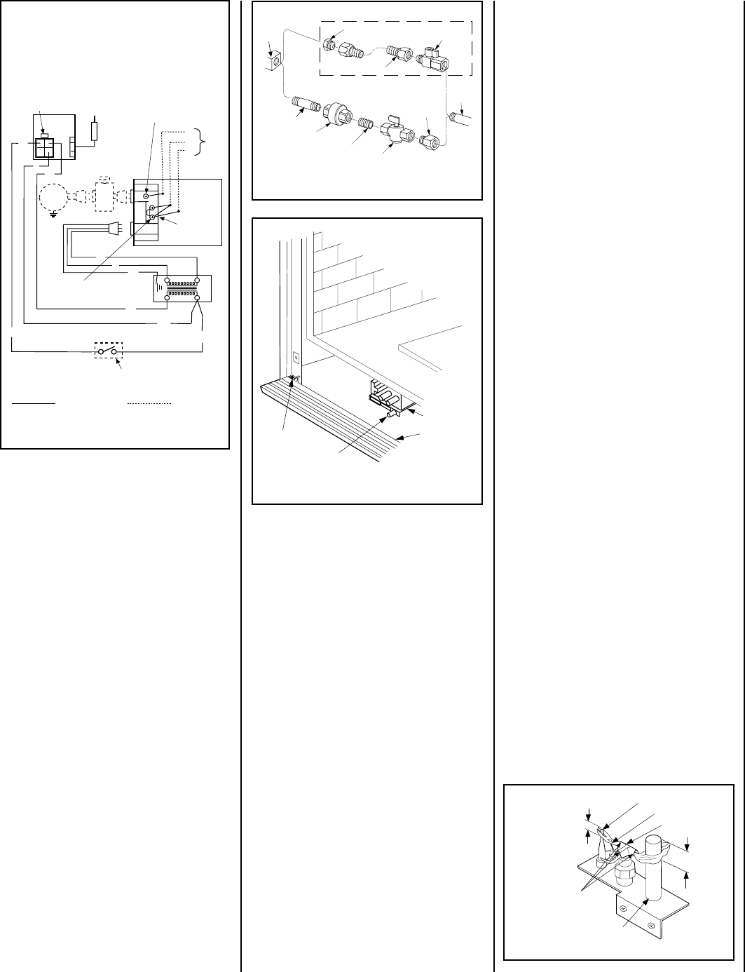
23
NOTE: DIAGRAMS & ILLUSTRATIONS NOT TO SCALE.
Figure 52
Figure 54
Figure 53 -
GAS CONNECTION
Turn on gas supply and test for gas leaks using
a soapy water solution. Never use an open
flame to check for leaks.
A. Mix a 50% dish soap, 50% water solution.
B. Light the appliance (refer to the lighting
instructions provided in the Homeowner's Care
and Operation Instructions).
C. Brush all joints and connections with the
soapy water solution to check for leaks. If bubbles
are formed, or gas odor is detected, turn the gas
control knob to the “OFF” position. Either tighten
or refasten the leaking connection and retest as
described above.
D. When the gas lines are tested and leak
free, observe the individual tongues of flame
on the burner. Make sure all ports are open
and producing flame evenly across the
burner. If any ports are blocked, or partially
blocked, clean out the ports.
Step 6. CONNECTING GAS LINE
Make gas line connections. All codes require a
shut-off valve mounted in the supply line.
Fig-
ure 53
illustrates two methods for connecting
the gas supply. The flex-line method is accept-
able in the U.S., however, Canadian require-
ments vary depending on locality. Installation
must be in compliance with local codes.
These appliances are equipped with a gas flex
line for use (where permitted) in connecting the
unit to the gas line. A gas flex line is provided
to aid in attaching the direct vent appliance to
the gas supply. The gas flex line can only be
used where local codes permit. See
Figure 53
for flex line description. The flex line is rated for
both natural and propane gas. A manual shut
off valve is also provided with the flex line.
The gas control valve is located in the lower
control compartment. To access the valve pro-
ceed as follows: Open the control compart-
ment access panel
(Figure 54)
by actuating the
spring-loaded magnetic catches securing the
panel, gently depressing the outer top corners
of the panel until the catches "pop" the panel
free, allowing it to swing out and down to open.
The millivolt control valve has a ³⁄₈"
(10 mm) NPT thread inlet port. The electronic
control valve has a ¹⁄₂" (13 mm) NPT thread inlet
port and is fitted with a ¹⁄₂" x ³⁄₈" (13 mm x
10 mm) NPT fitting.
Secure all joints tightly using appropriate
tools and sealing compounds (ensure pro-
pane resistant compounds are used in pro-
pane applications). The top ³⁄₈" (10 mm) at the pilot generator
(thermopile) and the top ¹⁄₈" min (tip) of the
quick drop out thermocouple should be en-
gulfed in the pilot flame. The flame should
project 1" (25 mm) beyond the hood at all three
ports
(Figure 55)
.
Millivolt Appliance Checkout
The pilot flame should be steady and, not lifting
or floating. Flame should be blue in color with
traces of orange at the outer edge.
Step 7. INSTALLING LOG SET, VERMICU-
LITE AND CERAMIC FIBER CHUNKS
The log set, a bag of decorative volcanic stone
and a bag of glowing embers (rockwool) is
supplied in the unit. Refer to the Homeowner's
Care and Operating Instructions for detailed
placement instructions for the logs, decorative
volcanic stone and glowing embers.
Step 8. CHECKING APPLIANCE OPERATION
With gas line installed, run initial system
checkout before closing up the front of the
unit. Follow the pilot lighting instructions
provided in the Homeowner's Care and Op-
eration Instructions. For piezo ignitor loca-
tion see
Figure 54
(millivolt appliances only).
Note: Lighting instructions may also be found
on the pull out lighting instruction labels at-
tached to the gas control valve.
To access the
label, see the procedure on the previous page
described for accessing the gas control valve.
When first lighting the appliance, it will take
a few minutes for the line to purge itself of
air. Once purging is complete, the pilot and
burner will light and operate as indicated in
the instruction manual. Subsequent lightings
of the appliance will not require such purg-
ing. Inspect the pilot flame (remove logs, if
necessary, handling carefully).
Figure 55
Replace logs after pilot inspection.
To light the burner: turn “ON” the unit-mounted
ON/OFF switch or the wall-mounted ON/OFF
switch or the thermostat (depending on the
type of control installed), and rotate the gas
valve control knob counterclockwise to the
“ON” position.
Gas
Stub
¹₂" x ³₈" Flare
Shut-Off Valve
³₈" Flex Tubing
³₈" NPT x ³₈
Flare Fitting
³₈" Nipple
³₈" Union
³₈" Close Nipple
³₈" Shut-Off Valve
¹₂ x ³₈ "
Reducer
Gas
Valve
Gas Flex Line Connector
1. If any of the original wire as supplied must be replaced,
1. it must be replaced with Type AWM 105°C – 18 GA. wire.
2. 120V, 60Hz – Less than 3 amps.
BK
Transf.
120 V.
24 V
Factory Wired Field Wired
BL
Electronic Wiring Diagram (Honeywell)
Showing the Blower Wiring for the Optional
FBK-250 Kits
R
WH
BL
OPT
BLOWER
G
W
120
VAC.
BK
W
Gas Valve
B
R
IGNITER
PILOT
ASSEMBLY
BK
G
Outlet Box Green
Ground Screw
Hot side of Outlet
Schematic Representation Only
*ON/OFF Switch
(Integral with Gas Valve)
White Wire
To Opposite
Side
Optional FBK-250
Module
*Leave the ON/OFF switch, which is integral
with the gas valve, in the ON position.
G
OPTIONAL APPLIANCE-MOUNTED ON/OFF SWITCH
OR OPTIONAL WALL SWITCH OR OPTIONAL
THERMOSTAT OR OPTIONAL REMOTE RECEIVER
Piezo Ignitor
Gas Valve
Control
Compartment
Access panel
Hinge Pin
¹⁄₈" Min
(3 mm)
Thermocouple
Ignitor Rod
Hood
³⁄₈" Min
(9 mm)
Thermopile
MILLIVOLT HONEYWELL
Pilot
Nozzels
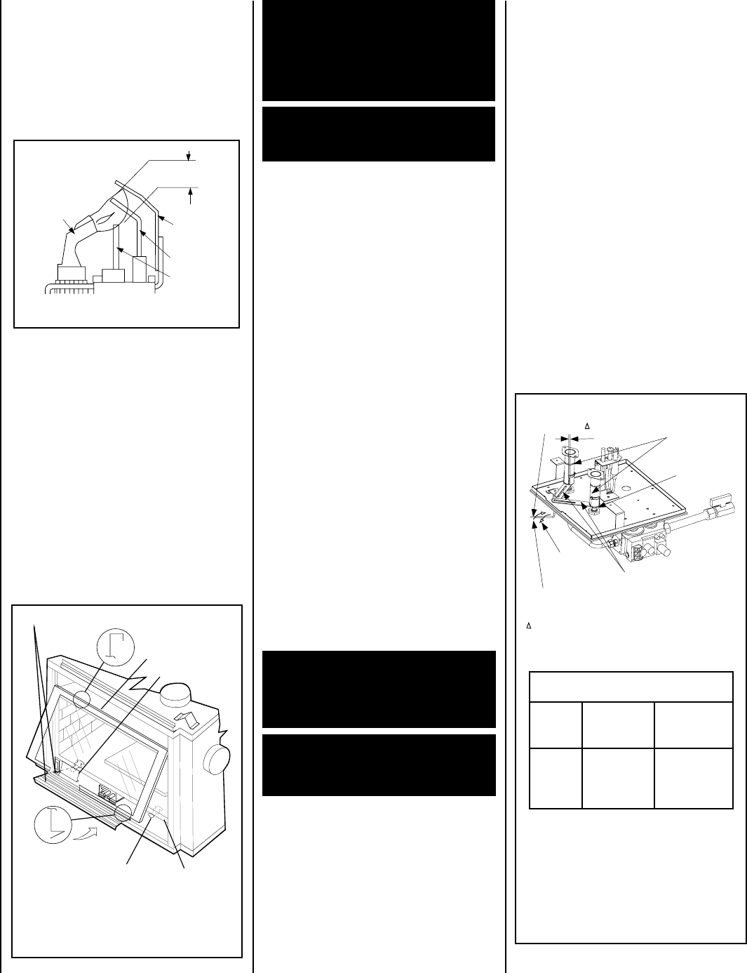
24 NOTE: DIAGRAMS & ILLUSTRATIONS NOT TO SCALE.
Glass Door
Latch
Control Compartment Access Panel and Hinge
Front Glass
Enclosure Panel
Firebox Floor
Bottom Vee-flange
Glass Door Frame
Top Flange
Glass Door Frame
Modesty Panel
CDST SHOWN
RENRUBNIAM*** GNITTESRETTUHSYROTCAF
sledoM saGlarutaN sehcni )mm(
saGenaporP sehcni )mm(
TSDC FPDC RCDC LCDC
OWT* 8/1)3(STOLS
OWT** 61/11)71(STOLS
Adjustment Rod Positions (when viewed
from above):
*Natural Gas
- fully clockwise
**Propane
- fully counter clockwise
*** Settings are shown for each burner.
Figure 57
INSTALLING THE GLASS DOOR
Figure 58
Air Shutter
Adjusting
Rod
Air Shutter
Adjusting
Arms
Orifice
Increase Shutter
Opening In This
Direction
Decrease Shutter
Opening In This
Direction
Air Shutter
Opening Burner
Venturi
Tube
Note - Both air shutters open and close simultaneously
when the air shutter adjusting rod is moved.
Note - Burners are omitted in this view for clarity.
ELECTRONIC
Proper Flame
Adjustment
Pilot
Nozzle
3/8 To 1/2 Inch
(9 mm to 13 mm)
Ground
Electrode
Flame Rod
Hot Surface
Igniter
Burner Adjustment
Sooting is indicated by black puffs developing at
the tips of very long orange flames. Sooting
results in black deposits forming on the logs,
appliance inside surfaces and on exterior sur-
faces adjacent to the vent termination. Sooting is
caused by incomplete combustion in the flames
and lack of combustion air entering the air
shutter opening. To achieve a warm yellow to
orange flame with an orange body that does not
soot, the shutter opening must be adjusted
between these two extremes.
No smoke or soot should be present. Reposition
the log set if flames impinge on any part of it.
If the log set is properly positioned and sooting
conditions exist, the air shutter opening on the
main burner tube should be adjusted. Normally,
the more offsets in the vent system, the greater
the need for the air shutter to be opened further.
Allow the burner to operate for at least 15
minutes. Observe the flame continuously. If it
appears weak or sooty as previously described,
adjust the air shutter by rotating the adjust-
ment rod until the flame appearance is as
desired.
Step 10. BURNER ADJUSTMENTS
Flame Appearance and sooting
Proper flame appearance is a matter of taste.
Generally, most people prefer the warm glow of
a yellow to orange flame. Appliances operated
with air shutter openings that are too large will
exhibit flames that are blue and transparent.
These weak, blue and transparent flames are
termed anemic. If the air shutter opening is too
small sooting may occur.
The adjustment rod and associated adjustable air
shutter is patented technology. Flame adjust-
ments can be made quickly and accurately to taste
without the need of disassembling the appliance
and waiting for 15 minutes after each adjustment.
Propane models may exhibit a flame pattern
that may candle or appear stringy. If this is
problematic or persists as the appliance is
continually operated, adjust the air shutter
closed as described in the previous paragraphs.
Operate the appliance for a period of time as the
effect diminishes, ensuring that the appliance
does not develop sooty flames.
When satisfied that the appliance operates prop-
erly, proceed to finish the installation. Leave the
control knob in the ON position and the remote
switch OFF. Close the lower control compart-
ment door.
CAUTION: THE AIR SHUTTER DOOR AND
NEARBY APPLIANCE SURFACES ARE HOT.
EXERCISE CAUTION TO AVOID INJURY WHILE
ADJUSTING FLAME APPEARANCE.
To adjust the flame, rotate the adjustment rod
(located in the lower control area) counterclock-
wise to increase or clockwise to reduce the air
shutter opening. Adjust the air shutter to the
recommended setting as shown in
Figure 58
.
WARNING: HANDLE THE GLASS WITH EX-
TREME CARE! TEMPERED GLASS IS SUS-
CEPTIBLE TO DAMAGE (SCRATCHES, FOR
EXAMPLE) –HANDLE GLASS DOORS
(GLASS ENCLOSURE PANELS) GENTLY
WHILE REINSTALLING THEM.
WARNING: NEVER OPERATE THE APPLIANCE
WITHOUT THE GLASS ENCLOSURE PANELS
IN PLACE AND SECURE.
WARNING: AIR SHUTTER ADJUSTMENT
SHOULD ONLY BE PERFORMED BY A
QUALIFIED PROFESSIONAL SERVICE
TECHNICIAN.
IMPORTANT: ENSURE THAT THE GLASS
ENCLOSURE PANELS ARE IN PLACE
AND SEALED DURING ADJUSTMENT.
Figure 56
Step 9. INSTALLING GLASS ENCLOSURE
PANELS
Electronic Appliance Checkout
To light the burner, turn ‘ON’ the the wall-
mounted ON/OFF switch or the thermostat
(depending on the type of control installed),
and turn the gas control switch to the “ON”
position. Ensure the ignitor lights the pilot. The
pilot flame should engulf the flame rod as
shown in
Figure 56
.
1. Visually inspect the gasket on the backside
of the panels. The gasket surface must be
clean, free of irregularities and seated firmly.
2. Position the glass enclosure panel in front
of the firebox opening at a 45 degree angle and
engage the top flange over the lip at the top of
the firebox opening.
See Figure 57.
3. Swing the glass enclosure panel down and
back. Ensure the gasket seats evenly as the
panel draws shut. Engage the Vee-flange at
the bottom of the panel with the latches and
close the latches to secure the panel.
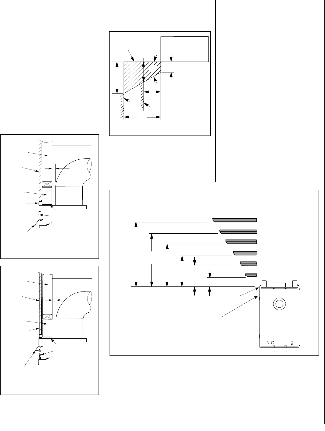
25
NOTE: DIAGRAMS & ILLUSTRATIONS NOT TO SCALE.
Combustible
Finished Wall
Materials
This Area Must Remain Clear
of Combustible Materials
Top of Appliance
1" Min
(25 mm)
Combustible
Wall Framing
Spacer
Clean Face Models
Top of Door Frame
Hood must be installed as shown.
Radiant panel
Drywall
Bracket/Spacer
Combustible Wall
Framing
Top of Appliance
Louver Face Models
Top of Door Frame
Hood must be installed as shown.
Louvers
Combustible
Finished Wall
Materials
This Area Must Remain Clear
of Combustible Materials
1" Min
(25 mm)
Combustible
Wall Framing
Spacer
Drywall
Bracket/Spacer
Combustible Wall
Framing
12 (305) MANTEL
10 (254) MANTEL
8 (203) MANTEL
6 (152) MANTEL
4 (102) MANTEL
4
(102)
14
(356) 12
(305) 10
(254) 2 (51) MANTEL
TOP OF
APPLIANCE
6
(152)
NOTE - Hood shown as positioned
in flush faced model. The hood
position in the louvered front model
is higher than shown.
8
(203)
MANTEL CLEARANCES
Inches (mm)
Figure 59
Figure 60
Figure 62
COLD CLIMATE INSULATION
If you live in a cold climate, seal all cracks around your appliance with noncombustible material and
wherever cold air could enter the room. It is especially important to insulate outside chase cavity
between studs and under floor on which appliance rests, if floor is above ground level.
Combustible materials may project beyond the
sides of the fireplace opening as long as they
are kept within the shaded areas illustrated in
Figure 61
.
Figure 61
A hearth extension is not required with this
appliance. If a hearth extension is used, do not
block the control compartment access panel.
Any hearth extension used is for appearance
only and does not have to conform to standard
hearth extension installation requirements.
17"
14" Min. Distance To
Unprotected Side Wall
8 ¹⁄₄"
45°
Combustible Materials
Allowed In Shaded
Area “Safe Zone”
12"
5"
Min. Distance
To Protected
Side Wall
Top View Of
Fireplace
Side
Wall Side
Wall
FINISHING REQUIREMENTS
Wall Details
Complete finished interior wall. To install the
appliance facing flush with the finished wall,
position framework to accommodate the thick-
ness of the finished wall (
Figures 59 and 60
)
Step 11. HOOD INSTALLATION
All of these appliances must have hoods
installed on all sides with glass enclosure
panels prior to operating.
On all clean face units, slide the hoods into the slots
on the lower edges of the radiant panels
(Figure 59)
.
On louvered face units, slide the hoods into the slots
on the lower edges of the cabinet top.
(Figure 60)
.
Note: Combustible wall finish materials and/
or surround materials must not be allowed to
encroach the area defined by the appliance
front face (black sheet metal). Never allow
combustible materials to be positioned in front
of or overlapping the appliance front face. See
Figures 59 or 60.
Non-combustible materials, such as sur-
rounds and other appliance trim, may be
installed on the appliance front face with
these exceptions: they must not cover any
portion of the glass or louvers; they may
cover any portion of the top radiant panel or
the air gaps surrounding the top radiant panel
up to the installed hood.
Vertical installation clearances to combus-
tible mantels vary according to the depth of
the mantel. See
Figure 62
. Mantels con-
structed of non-combustible materials may
be installed at any height above the appliance
opening; however, do not allow anything to
hang below the hood.
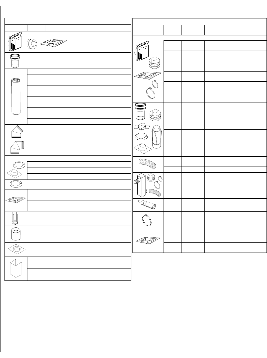
26 NOTE: DIAGRAMS & ILLUSTRATIONS NOT TO SCALE.
*All compressed flex vents can be expanded up to two times.
INSTALLATION ACCESSORIES
detsiL tneVeruceS stnenopmoC™
.oN.taC.oNledoMnoitpircseD
8691H2-TH5.4VSnoitanimreTerauqSlatnoziroH )08K69(recapS/potseriFhtiw )16L47(retpadAdna
2512H1-VGC5.4VSnoitanimreTlacitreV
07L776L5.4VSnoitceStneV)mm251(hcni6
17L7721L5.4VS tneV)mm503(hcni21 noitceS
27L7742L5.4VS tneV)mm016(hcni42 noitceS
37L7763L5.4VS tneV)mm419(hcni63 noitceS
47L7784L5.4VS tneV)mm9121(hcni84 noitceS
57L77AL5.4VSnoitceScipocseleT
67L7754E5.4VSwoblEeergeD54
77L7709E5.4VSwoblEeergeD09
.rallocmrotsahtiwdegakcapemocsgnihsalfgniwollofehT
87L77F5.4VSgnihsalFfooRtalF
97L77AF5.4VSgnihsalF.tsujdA21/7ot21/1
08L77BF5.4VSgnihsalF.tsujdA21/21ot21/7
18L776CS5.4VS)xob/sralloc6(sralloCmrotS
08K69FH5.4VS-recapS/potseriF )gnicaps1-1-3(latnoziroH
78K69FV5.4VS-recapS/potseriF )gnicaps1-1-1(lacitreV
39K69US5.4VSpartStroppuS
49K69ASR5.4VSdleihSnoitalusnIcittA
29K69PS5.4VSetalPtroppuS
25M715.4VS 1-SGH erauqSdrauGtaeH )kcaP-1(
35M715.4VS 21-SGH erauqSdrauGtaeH )kcaP-21(
detsiL xelFeruceS stnenopmoC™
.taC .oN ledoM .oN noitpircseD
.retpadaxelfdnaspmalcraeg,recaps/potserifedulcnistiknoitanimretesehT
9691H2-TH5.4FSnoitanimreTerauqSlatnoziroH xelFtuohtiw
78L7721TIKFS.ni21htiw.mreTerauqSxelF xelFdesserpmoc*fomm503(
88L7781TIKFS.ni81htiw.mreTerauqSxelF xelFdesserpmoc*fo)mm754(
98L7742TIKFS.ni42htiw.mreTerauqSxelF xelFdesserpmoc*fo)mm016(
09L7763TIKFS.ni63htiw.mreTerauqSxelF xelFdesserpmoc*fo)mm419(
19L7784TIKFS.ni84htiw.mreTerauqSxelF xelFdesserpmoc*fo)mm9121(
47L6503TVFSottalf(xelFrof.nimreTlacitreV noitces,retpadAxelFhtiw)21/6 ralloctroppusfoor,tnevdigirfo dnagnihsalffoor,ylbmessa .rallocmrots
57L6554TVFS21/6(xelFrof.nimreTlacitreV retpadAxelFhtiw)21/21ot foor,tnevdigirfonoitces foor,ylbmessaralloctroppus .rallocmrotsdnagnihsalf
01L0681-FSdesserpmoc*)m94.5(.tf81 xelF
30K8921-FSxelFdesserpmoc*)m66.3(.tf21
10L78KRHFSxelFhtiwtiKresiRlekronS dna,xelFfonoitcesa,retpadA spmalCraeG
18K01PMFSerutarepmeT-iHkcalBcaPliM tnalaeS
66L196-4CG-FS)mm411(.ni5.4pmalCraeG )seceip6(xelFrof
76L196-7CG-FS)mm5.091(.ni5.7pmalCraeG )seceip6(xelFrof
04M91FH5.4FS-recapS/potseriF )gnicaps1-1-3(latnoziroH
14M91FB5.4FS-recapS/potseriF )gnicaps1-1-1(lacitreV
Se
a
l
a
nt
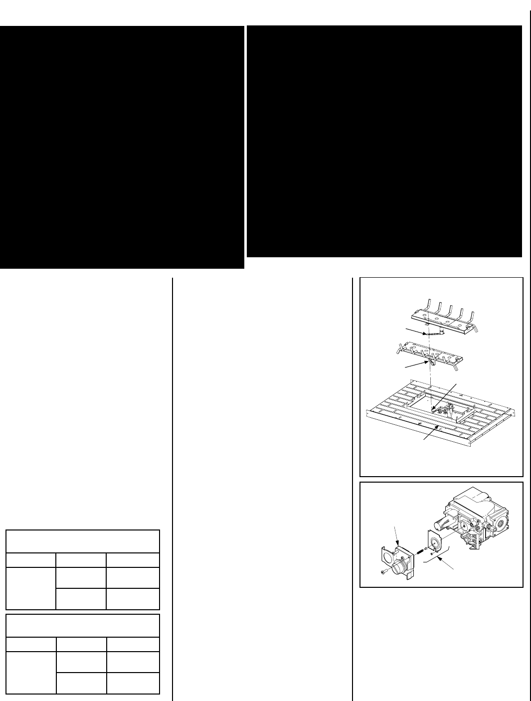
27
NOTE: DIAGRAMS & ILLUSTRATIONS NOT TO SCALE.
tiKnoisrevnoCsaGenaporPoTlarutaN
.oNsledoMepyTtinU.oNgolataC
TSDC FPDC RCDC LCDC
tlovillim56L58
cinortcele97L58
tiKnoisrevnoCsaGlarutaNotenaporP
.oNledoMepyTtinU.oNgolataC
TSDC FPDC RCDC LCDC
tlovillim27L58
cinortcele68L58
Figure 63
FRONT OF FIREPLACE
REAR BURNER
FRONT BURNER
VENTURI
TUBE ARM
VENTURI
TUBE ARM AIR SHUTTER
ADJUSTMENT LEVER
FIREBOX SUBFLOOR
NOTE: REMOVE FRONT BURNER FIRST,
THEN REAR BURNER.
GAS CONVERSION KITS
In Canada:
THE CONVERSION SHALL BE CARRIED OUT
IN ACCORDANCE WITH THE REQUIREMENTS
OF THE PROVINCIAL AUTHORITIES HAVING
JURISDICTION AND IN ACCORDANCE WITH
THE REQUIREMENTS OF THE CAN1-B149.1
AND .2 INSTALLATION CODE.
LA CONVERSION DEVRA ÊTRE EFFECTUÉE
CONFORMÉMENT AUX RECOMMANDATIONS
DES AUTORITÉS PROVINCIALES AYANT
JURIDICTION ET CONFORMÉMENT AUX
EXIGENCES DU CODE D'INSTALLATION CAN1-
B149.1 ET.2.
Gas conversion kits are available to convert
your appliance from the use of one type of gas
to the use of another. These kits contain all the
necessary components needed to complete the
task including labeling that must be affixed to
ensure safe operation.
Kit part numbers are listed here and the following
steps detail the conversion procedure.
Figure 64
Pressure
Regulator
Remove
These
Components
WARNING: THIS CONVERSION KIT SHALL BE
INSTALLED BY A QUALIFIED SERVICE AGENCY IN
ACCORDANCE WITH THE MANUFACTURER'S IN-
STRUCTIONS AND ALL APPLICABLE CODES AND
REQUIREMENTS OF THE AUTHORITY HAVING JU-
RISDICTION. IF THE INFORMATION IN THESE
INSTRUCTIONS IS NOT FOLLOWED EXACTLY, A
FIRE, EXPLOSION OR PRODUCTION OF CARBON
MONOXIDE MAY RESULT CAUSING PROPERTY
DAMAGE, PERSONAL INJURY OR LOSS OF LIFE.
THE INSTALLATION IS NOT PROPER AND COM-
PLETE UNTIL THE OPERATION OF THE CONVERTED
APPLIANCE IS CHECKED AS SPECIFIED IN THE
OWNER INSTRUCTIONS SUPPLIED WITH THE KIT.
THE QUALIFIED SERVICE AGENCY PERFORMING
THIS INSTALLATION ASSUMES RESPONSIBILITY
FOR THIS CONVERSION.
AVERTISSEMENT: CET ÉQUIPEMENT DE CONVERSION
SERA INSTALLÉ PAR UNE AGENCE QUALIFIÉE DE SER-
VICE CONFORMÉMENT AUX INSTRUCTIONS DU
FABRICANT ET TOUTES EXIGENCES ET CODES
APPLICABLES DE L'AUTORISÉS AVOIR LA JURIDICTION.
SI L'INFORMATION DANS CETTE INSTRUCTION N'EST
PAS SUIVIE EXACTEMENT, UN FEU, EXPLOSION OU PRO-
DUCTION DE PROTOXYDE DE CARBONE PEUT RÉSULTER
LE DOMMAGES CAUSER DE PROPRIÉTÉ, PERTE OU
BLESSURE PERSONNELLE DE VIE. L'AGENCE QUALIFIÉE
DE SERVICE EST ESPONSABLE DE L'INSTALLATION
PROPRE DE CET ÉQUIPMENT. L'INSTALLATION N'EST
PAS PROPRE ET COMPLÉTE JUSQU'À L'OPÉRATION DE
L'APPAREIL CONVERTI EST CHÉQUE SUIVANT LES
CRITÈRES ÉTABLIS DANS LES INSTRUCTIONS DE
PROPRIÉTAIRE PROVISIONNÉES AVEC L'ÉQUIPEMENT.
Millivolt Appliances
Step 4. Refer to
Figure 64
and the instructions
provided with the kit. Using a Torx T20, remove
and discard the three pressure regulator mount-
ing screws. Remove the pressure regulator,
spring, poppet, diaphragm and bushing. Dis-
card all removed components. Ensure the
rubber gasket installed on the back of the
replacement pressure regulator is properly
positioned and install the new pressure regula-
tor using the new screws supplied with the kit.
Tighten screws to 25 In. lb. torque.
Step 1. Turn off the gas supply to the appliance.
a. Open the control compartment access panel,
by actuating the spring-loaded magnetic catches
securing the panel, gently depressing the outer
top corners of the panel until the catches "pop"
the panel free and allowing it to swing out and
down to open.
b. Locate the two (2) latches at the top of the
control compartment. To disengage the two
latches from the bottom vee-flange of the glass
enclosure panel, reach for the handles located
towards the back of the latches and pull the
handles down toward the front of the unit.
c. Swing the bottom of the door out and raise
it slightly to lift the top flange of the door frame
away from the appliance.
Step 2. Carefully remove the log set. Exercise
care as not to break the log set.
Step 3. Referring to
Figure 63
, remove the
front burner and then the rear burner.
Step 5. Attach manometer to the manifold side
pressure test fitting and verify manifold pres-
sure reads 3.5 inches water column (0.87
KPa) for natural gas, and 10.0 inches water
column (2.49 kPa) for propane gas.
Step 6. Refer to
Figure 65 on page 28
and
remove the pilot hood assembly to access the
hexed pilot orifice. Remove and replace the
orifice with the one provided with the kit.
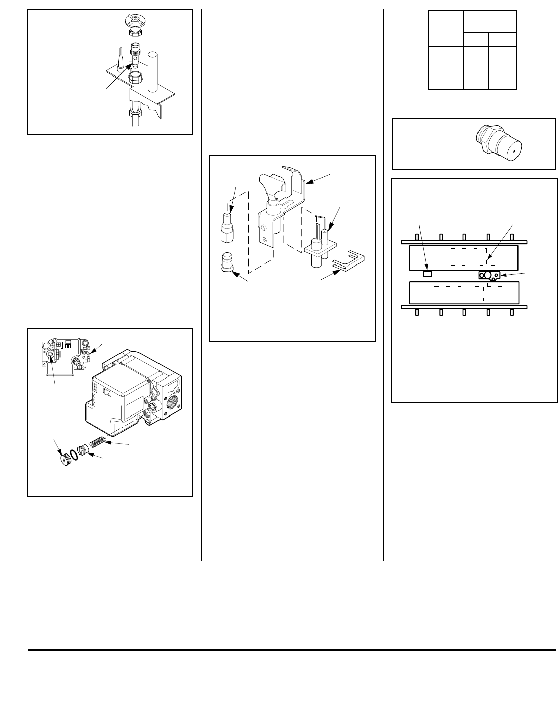
28 NOTE: DIAGRAMS & ILLUSTRATIONS NOT TO SCALE.
The manufacturer reserves the right to make changes at any time, without notice, in design, materials, specifications, prices and also to discontinue colors, styles and products.
Consult your local distributor for fireplace code information.
LHP
1110 West Taft Avenue • Orange, CA 92865
Printed in U.S.A. © 2002 by Lennox Hearth Products
P/N 700,001M REV. H 09/2005
Pilot
Orifice
Retaining
Clip
Ignitor
Assembly
Pilot
Assembly
Pilot
Orifice
Flare Nut
Note: If the ignitor is damaged, a replacement
kit is available, order Catalog No. 87L54.
BURNER POSITIONING
REAR BURNER
FRONT BURNER
PILOT
BURNER
Note: The burners are not identical. Position them so
that the circular burner ports run as shown. Note
especially the vertical run of ports relative to the pilot
burner. Bracket A on the rear burner will interfere with
the pilot burner if an attempt is made to install the
rear burner in the front burner’s position.
BRACKET A BURNER
PORTS
NOTE: INSTALL REAR BURNER FIRST,
THEN FRONT BURNER.
Spring
Adjusting
Screw
Slotted
Cap
PSI
OFF
I
ON
CONTROL
IGNITE
Manifold
Pressure
Test Port
Inlet Pressure Test Port
ledoM .oN
*ezisecifirO
.taN.porP
TSDC FPDC RCDC LCDC
44#55#
Figure 67
Figure 66
Figure 68
Figure 65
Figure 69
Remove the screw securing the pilot assembly
to its mounting bracket. Back off the flare nut
at the end of the pilot gas line to free the pilot
assembly from the gas line. Remove the pilot
orifice and replace it with the one provided with
the conversion kit. Reinstall the pilot assembly
by reversing the steps detailed here.
When reinstalling the ignitor assembly, use
extreme care to prevent damage and break-
age. Do not apply any leverage to the ignitor
assembly while restoring the retainer clip to
its original position.
* Each model has two burners. Each burner contains
one of these orifices.
NOTE: DIAGRAMS & ILLUSTRATIONS NOT TO SCALE.
Electronic Appliances
Step 7. Honeywell Electronic Valves - See
Figure 66
and the instructions provided with
the kit. Remove the slotted cap screw, o-ring,
pressure-regulating adjusting screw and
spring. Retain all parts for possible later use.
Install new components from the kit. Black
cap and red spring for propane gas units.
Silver cap and stainless steel spring for natural
gas units. Before installing the cap, attach
manometer to the manifold side pressure test
fitting and adjust screw until pressure reads
3.5 inches water column (0.87 kPa) for natural
gas, and 10.0 inches water column (2.49 kPa)
for propane gas.
Step 9. Reassemble the remaining compo-
nents by reversing the procedures outlined in
the preceding steps. Use pipe joint compound
or Teflon tape on all pipe fittings before install-
ing (ensure propane resistant compounds are
used in propane applications, do not use pipe
joint compounds on flare fittings).
Step 10. Attach the conversion label provided
in the conversion kit to the rating plate on the
appliance.
Step 11. Turn on gas supply and test for gas
leaks.
See
Figure 67
and replace the pilot orifice as
follows: Remove the ignitor assembly retainer
clip, and carefully remove the ignitor assembly.
Exercise extreme care to prevent damage to
or breakage of the ignitor assembly.
All Models
Step 8. (Refer to
Figure 63 on page 27
)
A. Remove the two orifices from the manifold
and replace them with the ones provided in the
kit. The following table shows the orifice sizes
for natural and propane models
. Figure 68
illustrates the orifice.
B. Install rear burner first, followed by front
burner, as shown in
Figure 69
. Ensure that the
arm of the venturi of each burner is hooked
onto the air shutter adjustment lever (refer to
Figure 63 on page 27).
The primary air open-
ing can be adjusted by rotating the adjustment
lever from beneath the firebox floor. Refer to
Figure 58 on page 23
for the recommended
minimum primary air opening setting.
