User manual
www.supremainc.com
BioLite NET
Innovative Fingerprint Terminal
User Guide (ver 1.0)
User guide( ver 1.0 )
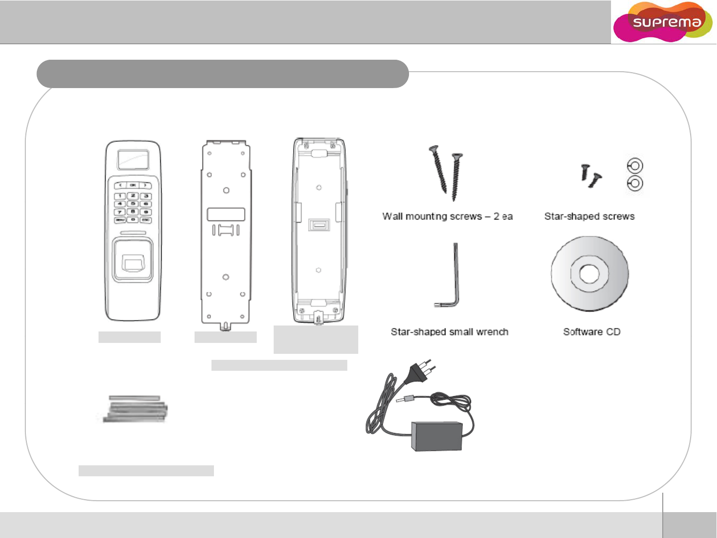
Product Contents
Basic Contents
Product Contents
Product
Contents
EE--ringring
Main Body
Sub
b
ra
c
k
e
t
Default
Wall-mounting metal bracket
Main
Body
Sub b c e
(optional)
Default
zRecommended power supply
12V ±10%, at least 2500mA for BioLite-NET
Shrinking Tube
alone installation.
Comply with standard IEC/EN 60950-1
(CE Certification).
To share the power with other devices,
use a power supply with higher current ratings.
2
ⒸCopyright 2008 Suprema Inc.
Before Start
12V power adaptor
(optional)
Shrinking
Tube
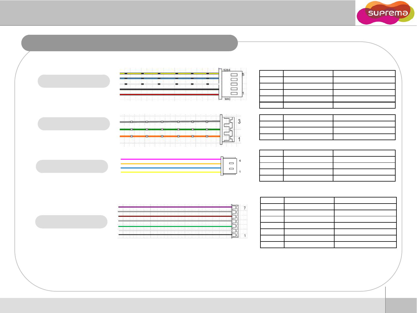
Cable spec.
PIN POWER + 485 WIRE
1
POWER (12Vd )
RED
1
POWER
+
(12Vd
c
)
RED
2 POWER GND BLACK
3 485 GND WHITE(Black String)
4 485 + BLUE(Black String)
5 485 - YELLOW(Black String)
Power & 485
PIN
RELAY
WIRE
Relay
PIN
RELAY
WIRE
1 NORMAL CLOSE ORANGE(White String)
2 COMMON GREEN(White String)
3 NORMAL OPEN GRAY(White String)
PIN SWITCH WIRE
Ethernet
1ERX - YELLOW
2ERX + BLUE
3ETX - ORANGE
4ETX + PINK
Switch & Wiegand
PIN SWITCH&WIEGAND WIRE
1WGND BLACK
2WDATA 1 WHITE
3WDATA 0 GREEN
4GND GRAY
5SWIN 1 BROWN
6GND GRAY
7SWIN 0 PURPLE
3
ⒸCopyright 2008 Suprema Inc.
Before Start
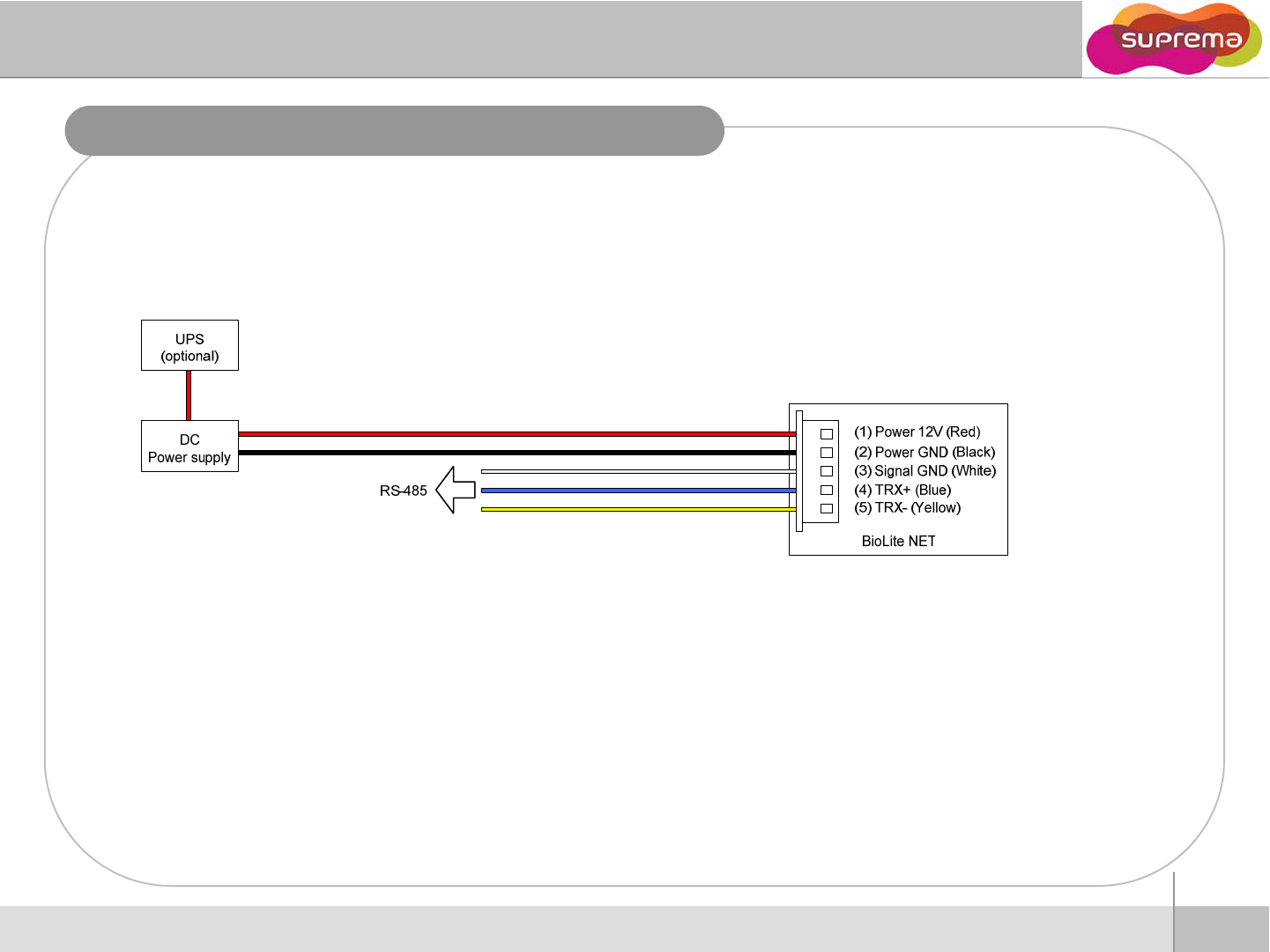
Power Connection
Recommended power supply
z12V ±10%, at least 1000mA.
zTo share the power with other devices, use a power supply with higher current ratings.
4
ⒸCopyright 2008 Suprema Inc.
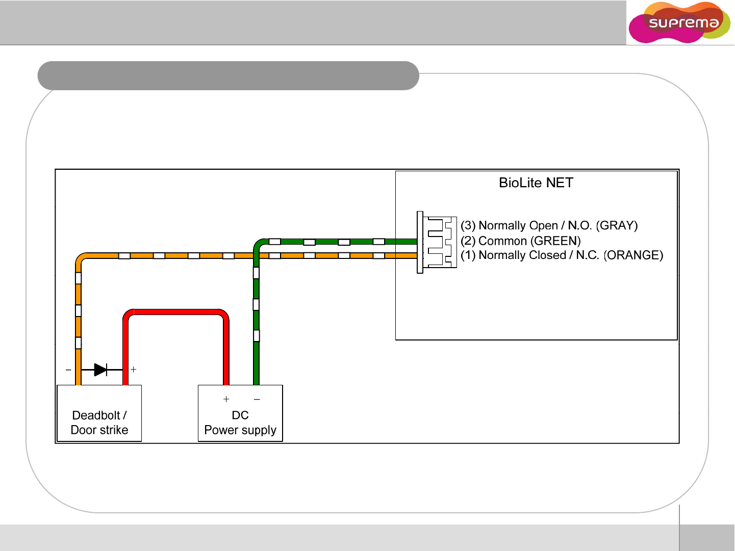
Relay Connection – Fail safe loc
k
5
ⒸCopyright 2008 Suprema Inc.
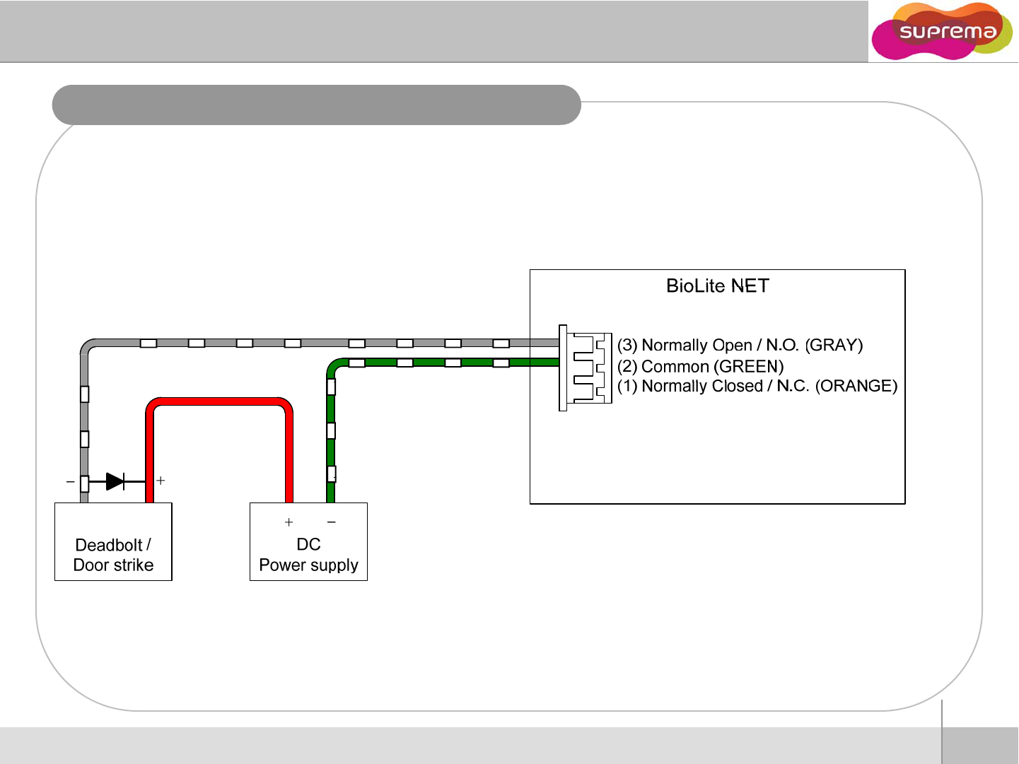
Relay Connection – Fail secure loc
k
6
ⒸCopyright 2008 Suprema Inc.
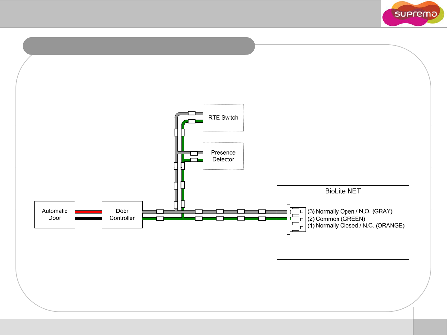
Relay Connection - Automatic door
7
ⒸCopyright 2008 Suprema Inc.
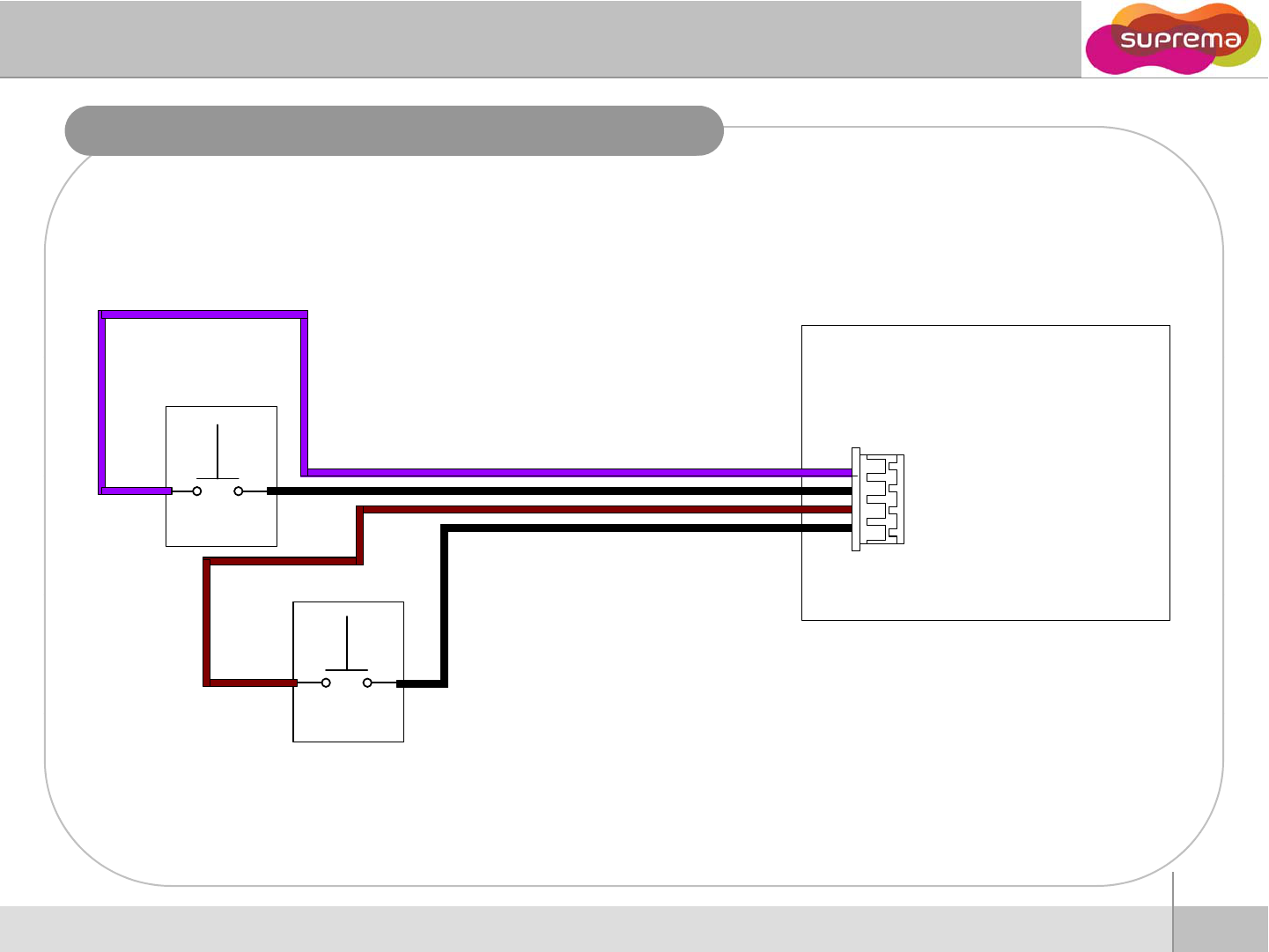
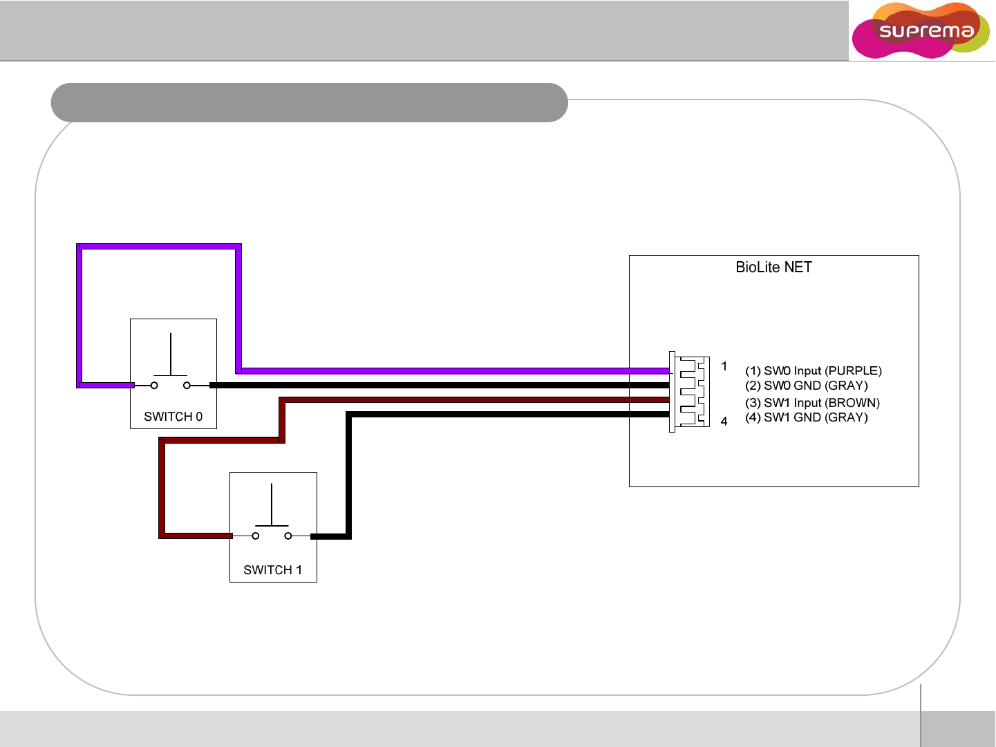
Door switch connection
BioLite NET
(
1
)
SW
0
Input
(
PURPLE
)
1
Door Status
(
1
)
SW
0
Input
(
PURPLE
)
(2) SW0 GND (GRAY)
(3) SW1 Input (BROWN)
(4) SW1 GND (GRAY)
4
Re
q
uest To
q
Exit
8
ⒸCopyright 2008 Suprema Inc.
Switch connection (Alarm, Emergency switches)
9
ⒸCopyright 2008 Suprema Inc.
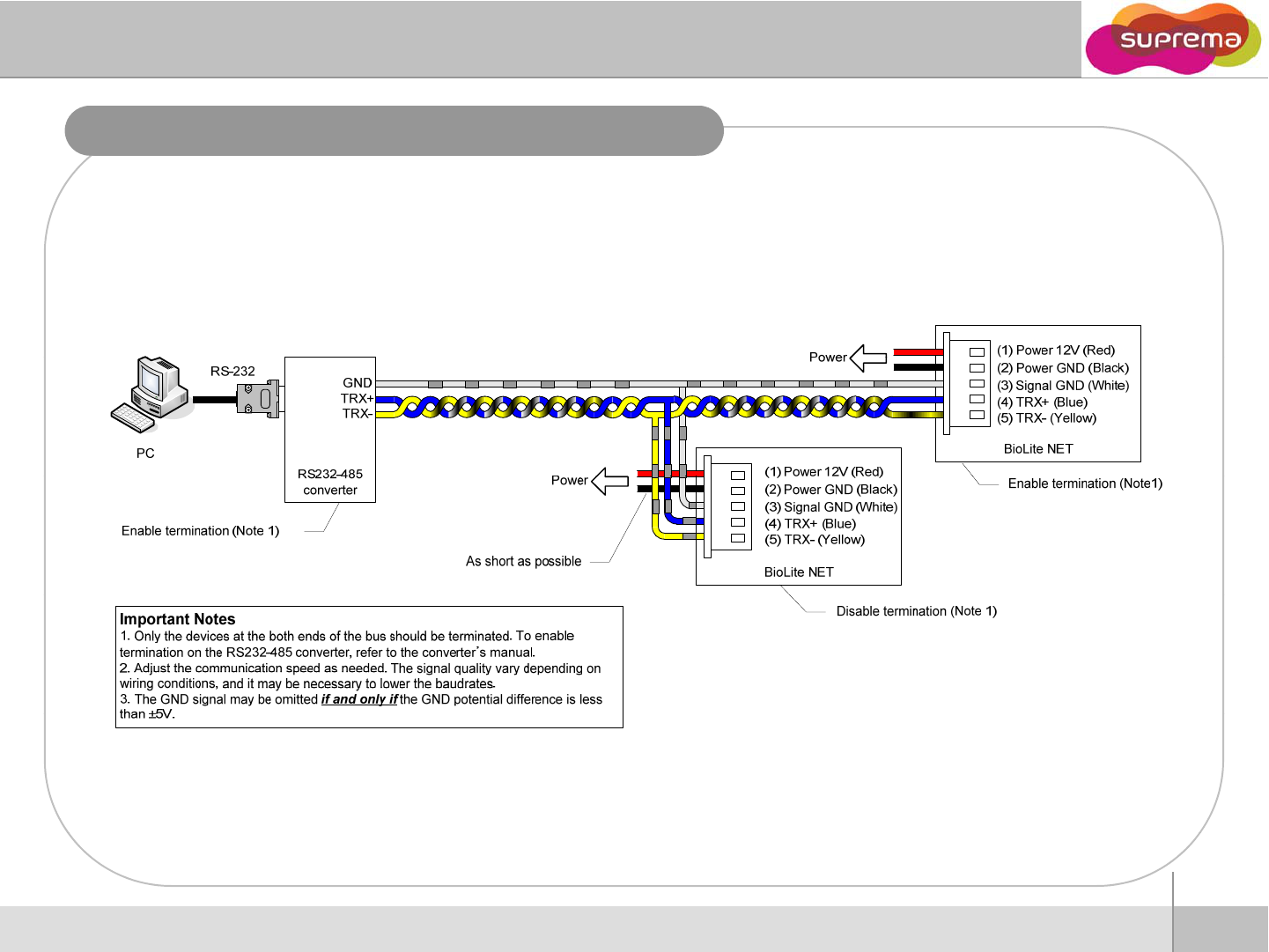
RS485 connection for host communication
10
ⒸCopyright 2008 Suprema Inc.
Before Start
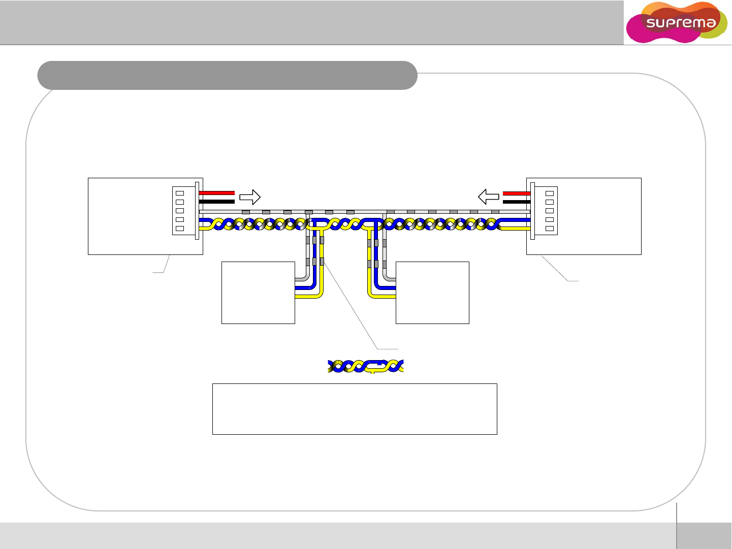
RS485 connection for Secure I/O
(
2
)
Power GND
(
Blac
k
)
(1) Power 12V (Red)
Power
(2) Power GND (Black)
(1) Power 12V (Red) Power
BioLite NET (Master) BioLite NET (Slave)
*
Eblt iti
(5) TRX- (Yellow)
(4) TRX+ (Blue)
(3) Signal GND (White)
(
)
(
)
(5) TRX- (Yellow)
(4) TRX+ (Blue)
(3) Signal GND (White)
*Enable termination
(
ti l
Nt
1
)
TRX-
TRX+
TRX GND
*
E
na
bl
e
t
erm
i
na
ti
on
(optional, see Note1)
Secure I/O
TRX-
TRX+
TRX GND
Secure I/O
..
.
(
op
ti
ona
l
, see
N
o
t
e
1
)
As short as possible (Note 2)
Important Notes
1. For bus termination, only the devices at both ends of the bus should be terminated.
Tbltiti thRS
232
485
t
ftth t
’
l
T
o ena
bl
e
t
erm
i
na
ti
on on
th
e
RS
232
-
485
conver
t
e
r
, re
f
er
t
o
th
e conver
t
e
r
’
s manua
l
.
2. The stubs should be as short as practical
11
ⒸCopyright 2008 Suprema Inc.
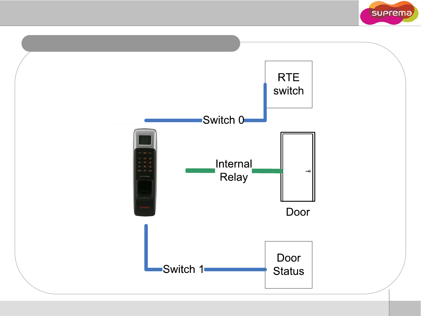
Installation Reference - Stand alone
12
ⒸCopyright 2008 Suprema Inc.
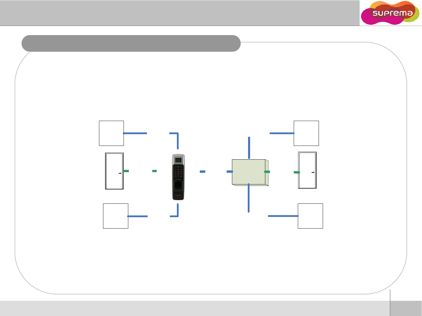
Installation Reference – Using Secure I/O, 2 door
RTE
switch
Switch 0Switch 0
RTE
switch
Secure
I/O
Doo
r
1
Relay 0
Door
0
Internal
Relay RS485
Door
0
Door
Status
Switch 1
Door
Status Switch 1
13
ⒸCopyright 2008 Suprema Inc.
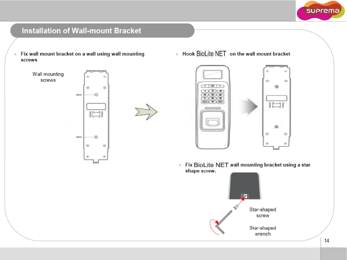
14
ⒸCopyright 2008 Suprema Inc.
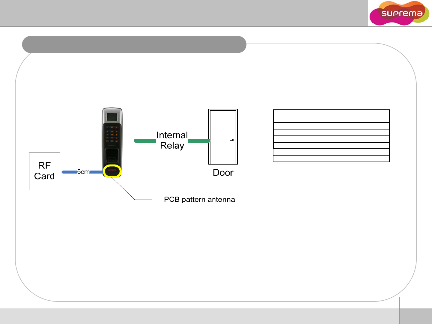
Installation Reference – Using RFID card
item content
Model BioLite-NET
(
BLN-OC
)
(
)
Transmit 13.56MHz
Receive 13.56MHz
Modulation ASK
Communication Single propagation
Channel Single channel
Mode 1:1
Using RFID card (13.56MHz = Mifare model only)
zIn case 1:1 mode is set as RF Card
zIf the 1:1 mode is set as Card Only, user can access just by placing the card to BioLite-NET
without any additional procedure.
15
ⒸCopyright 2008 Suprema Inc.
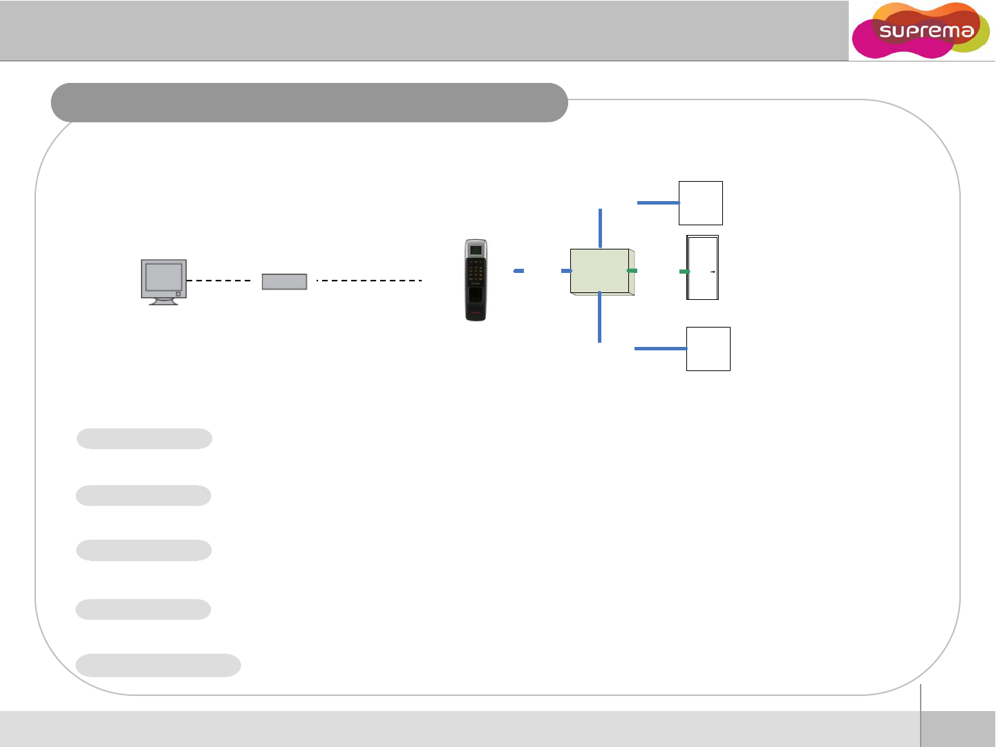
Installation Reference – LAN
Secure
I
/
O
Relay 0
RS485
RTE
switch
Switch 0
Network hub Ethernet
I
/
O
Door 1
Door
Status
Switch 1
If you select Network on initial UI menu, Network Setup menus appear on the display.
If you select TCP/IP on network menu, following menus appear on the display.
zSetting : Disable/Ethernet
zUsed when connected to PC via Ethernet using RJ45 connector on the rear of the device.
LAN TYPE
zSetting : 1/4/8/16
zMax number of clients that can access the device at the same time.
zSetting : Use/not use.
z
It sets Use or Not Use of S
SL between the TEST UI and BioLite
NET
Max conn
SSL
z
It
sets
Use
or
Not
Use
of
S
SL
between
the
TEST
_
UI
and
BioLite
-
NET
.
zSetting : Use/not use
zUsing DHCP, you can receive IP address and other necessary setting from server automatically.
zCheck whether an appropriate DHCP server is available in your network environment before use.
DHCP
16
ⒸCopyright 2008 Suprema Inc.
zWithout using DHCP, IP address, gateway, and subnet need to be entered manually. Inquire
necessary settings to network administrator.
IP Address, gateway, subnet
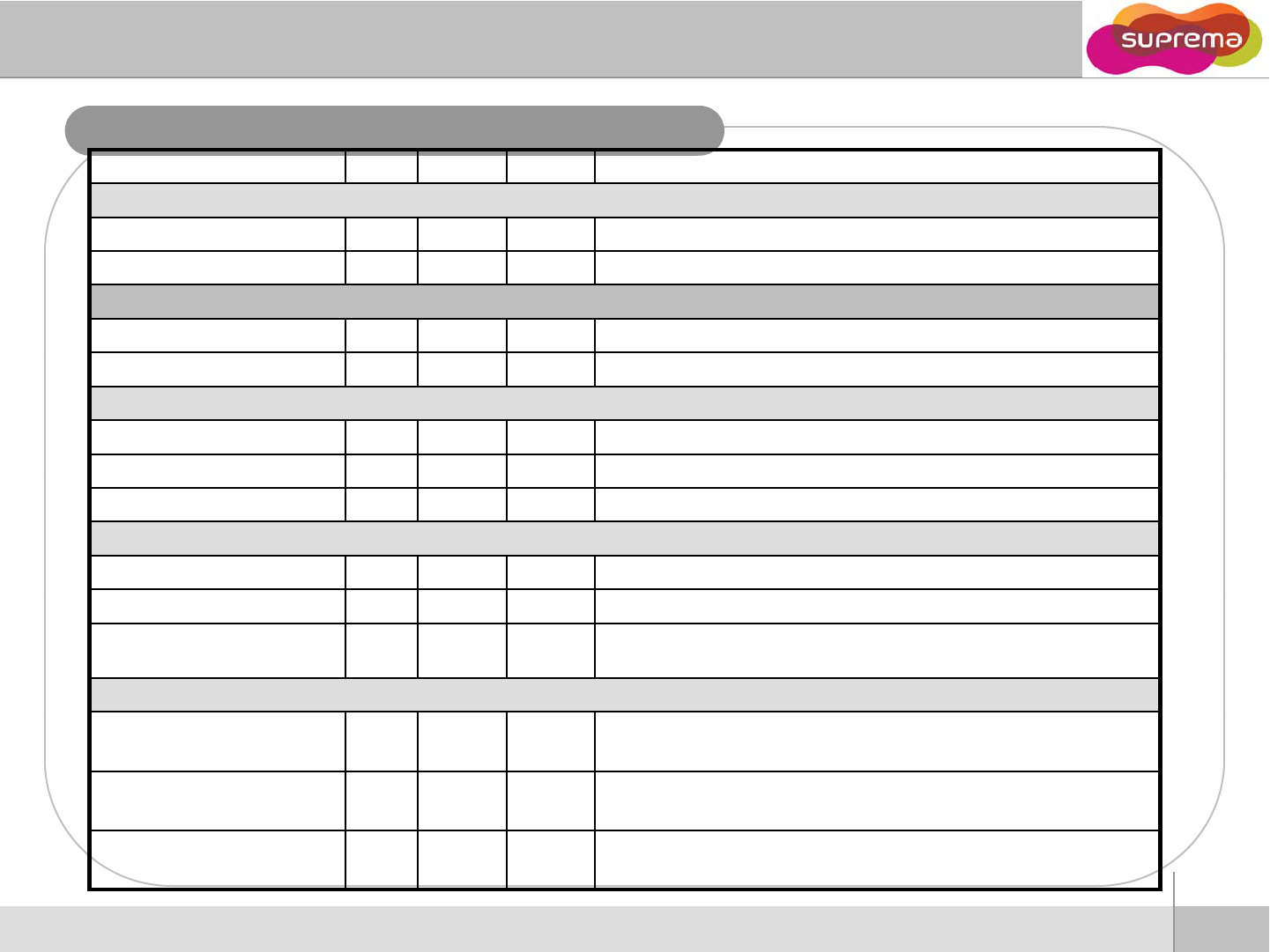
Electrical Specification
Min. Typ. Max. Notes
Power
Voltage (V)
10 8
12
13 2
Use regulated DC power adaptor only
Voltage
(V)
10
.
8
12
13
.
2
Use
regulated
DC
power
adaptor
only
Current (mA) - 250
RTC Battery
Voltage (V) 2.7 3 3.3 Lithium-ion rechargeable battery
Current (mAH) -11
Switch Input
VIH (V) -TBD -
V
IL
(V)
-
TBD
V
IL
(V)
TBD
Pull-up resistance (Ω)- 4.7k - The input ports are pulled up with 4.7k resistors
TTL/Wiegand Output
VOH (V) -5 -
VOL (V) -0.8 -
Pull-up resistance (Ω)-4.7k -
The outputs ports are open drain type, pulled up with 4.7k resistors
internally
Relay
Switching capacity (A) -- 1
0.3
30V DC
125V AC
Switching power (resistive) --
30W
37.5VA
DC
AC
17
ⒸCopyright 2008 Suprema Inc.
Switching voltage (V) --
110
125
DC
AC
18
ⒸCopyright 2008 Suprema Inc.

Troubleshooting
Fingerprint can not be read well or it takes too long.
zCheck whether a fin
g
er or fin
g
er
p
rint sensor is stained with sweet
,
water or dust
ggp ,
zRetry after wiping off finger and fingerprint sensor with dry towel.
zIf a fingerprint is way too dry, blow on the finger and retry.
Fingerprint is entered but authorization keeps failing.
z
Check whether the user is restricted by door zone or time zone
z
Check
whether
the
user
is
restricted
by
door
zone
or
time
zone
zInquire of administrator whether the enrolled fingerprint has been deleted from the device for some
reason
Authorized but door is not opened.
z
Check whether the time is set as lock time
z
Check
whether
the
time
is
set
as
lock
time
.
zCheck whether an antipass back mode is in use. In antipass back mode, only who entered can exit.
Device doesn’t operate though power is connected.
zCheck whether a device and a bracket is well connected to each other. If not, a tamper switch is
activated and the device doesn
’
twork
activated
and
the
device
doesn t
work
.
RTC Battery caution.
zRisk of explosion if battery is replaced by an incorrect type.
zDispose of used batteries according to the instructions.
19
ⒸCopyright 2008 Suprema Inc.
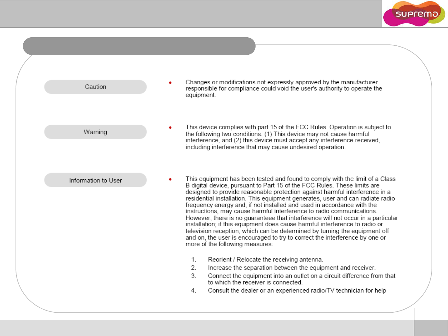
FCC Rules
20
ⒸCopyright 2008 Suprema Inc.

Tel : 82-31-710-2400
Fax : 82-31-783-4506
21
ⒸCopyright 2008 Suprema Inc.