Suprema BLROC BioLite Net User Manual
Suprema Inc. BioLite Net
UserManual.wiki
>
Suprema
>
BLROC User Manual
User manual
Navigation menu
Upload a User Manual
Namespaces
Wiki Guide
HTML
PDF
Info
Views
User Manual
Discussion / Help
Navigation
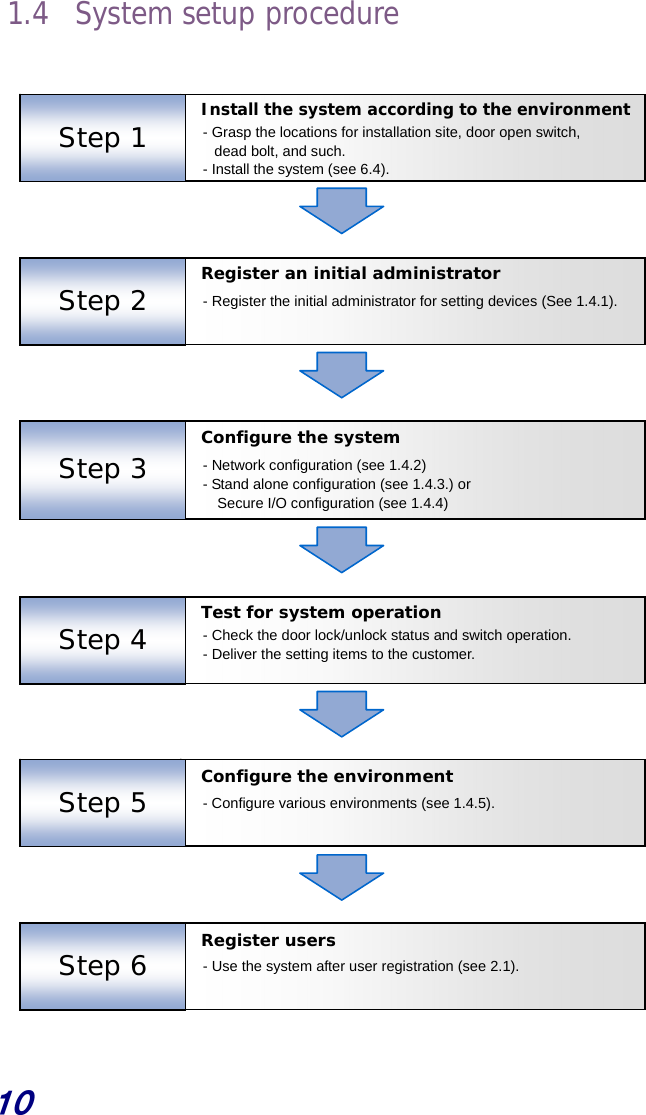
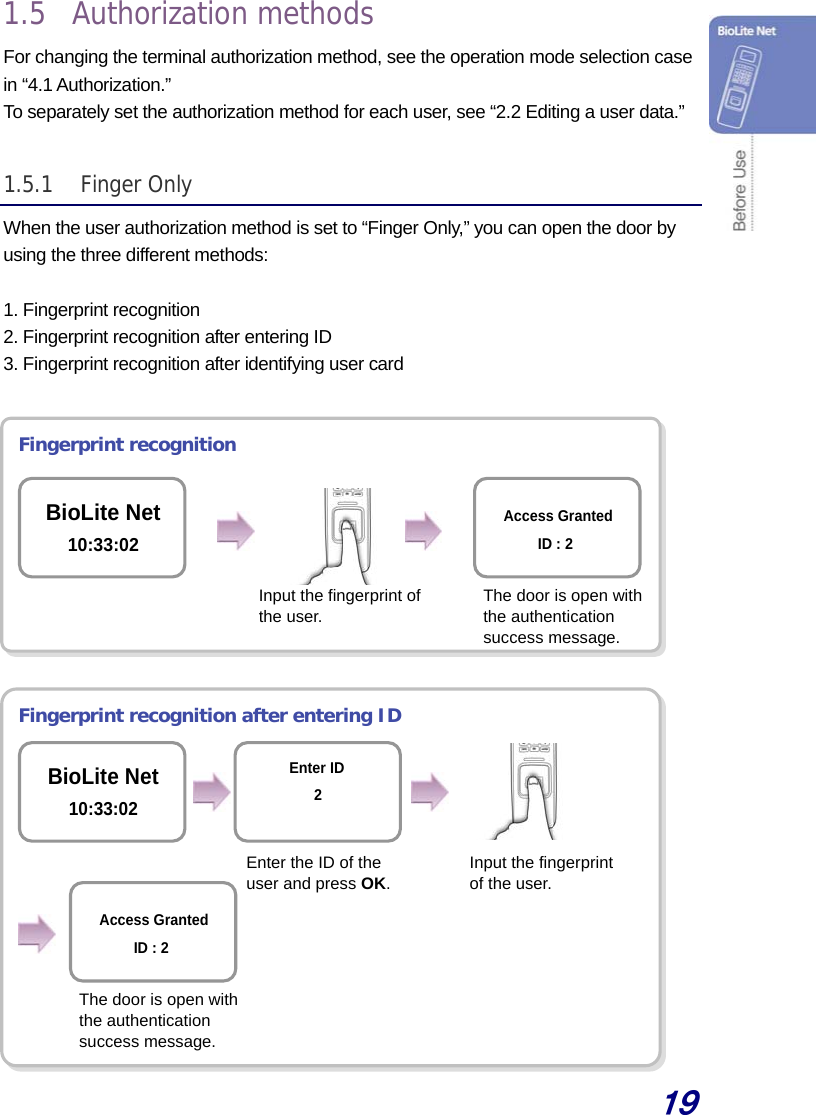
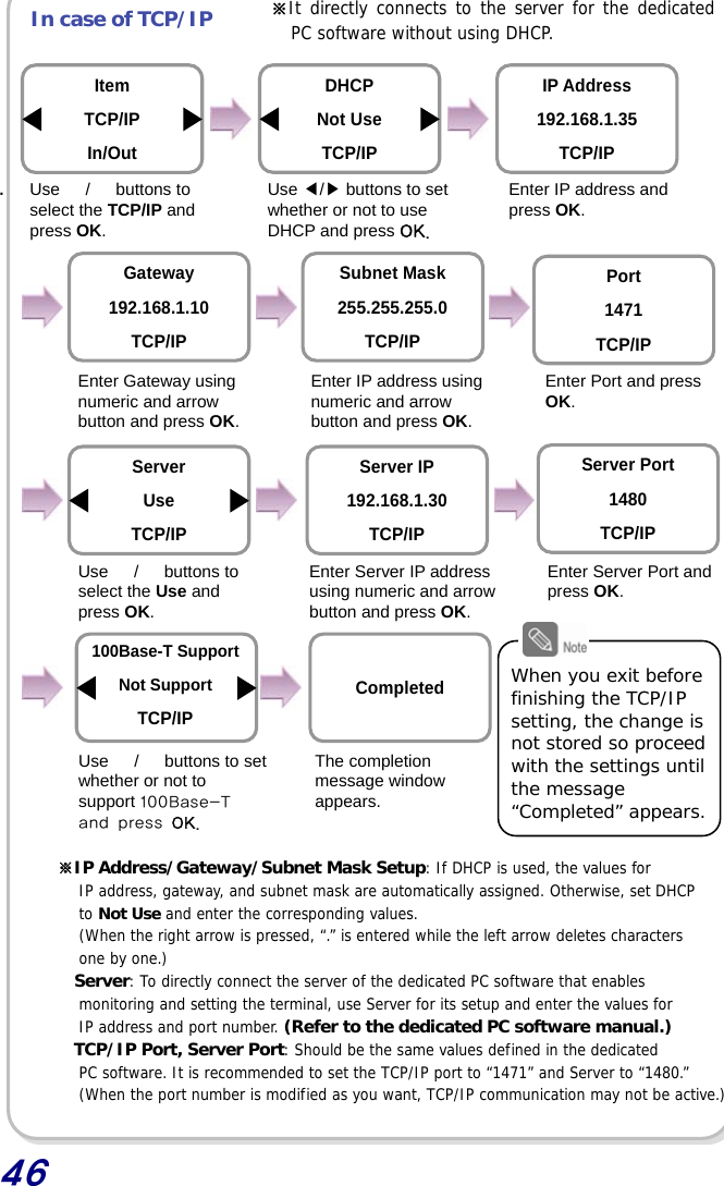
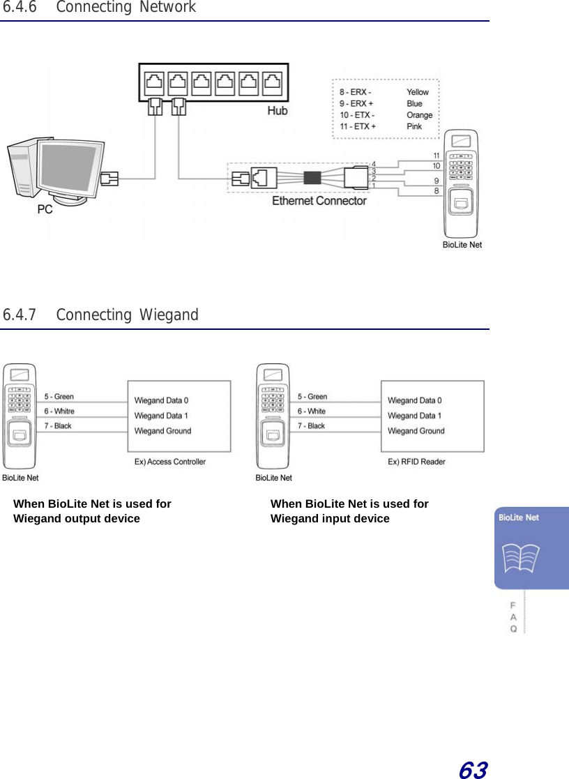
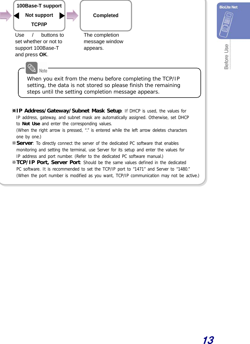
![12 1.4.2 Network configuration The network configuration is required to connect the dedicated PC software or other devices via network. Configure the settings according to the communication environment in your place. [In case of configuring the network via Ethernet] 1. Connect the terminal to the computer that has the dedicated PC software according to the network environment after seeing “6.4.6 Connecting network.” 2. Configure the settings for TCP/IP port and server according to the installation environment. Use / buttons to set whether or not to use DHCP and press OK. Server IP 192.168.1.30 TCP/IP Server Port 1480 TCP/IP Subnet Mask 255.255.255.0 TCP/IP Server Use TCP/IP Port 1471 TCP/IP Item TCP/IP In/Out Device In/OutDHCP Not Use TCP/IP IP Address 192.168.1.35 TCP/IP Gateway 192.168.1.10 TCP/IP ※ The following example explains how to directly connect the server PC without using DHCP. Use / buttons to select the Device icon and press OK. Use / buttons to select the In/Out icon and press OK. Use / buttons to select the TCP/IP and press OK. Enter the IP address and press OK.Enter Port and press OK. Enter Server Port and press OK. Enter the Gateway using numeric and arrow buttons and press OK. Enter Server IP address using numeric and arrow button and press OK. Enter IP address using numeric and arrow button and press OK. Use / buttons to select the Use and press OK. Cont.](https://usermanual.wiki/Suprema/BLROC/User-Guide-1105454-Page-12.png)
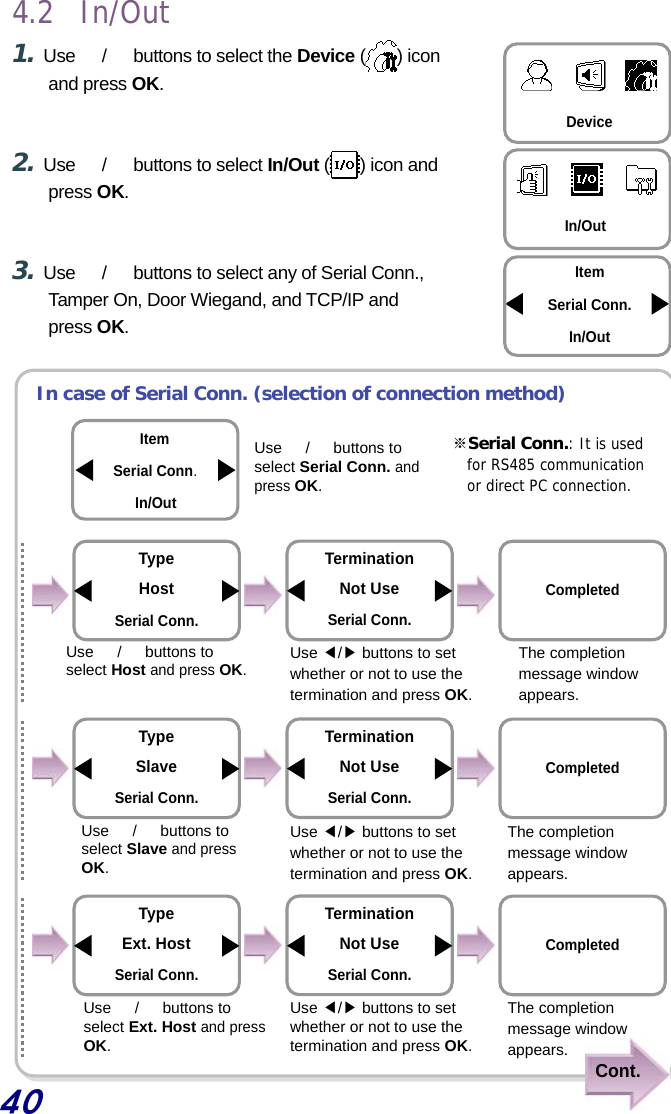
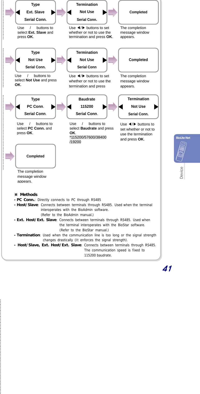
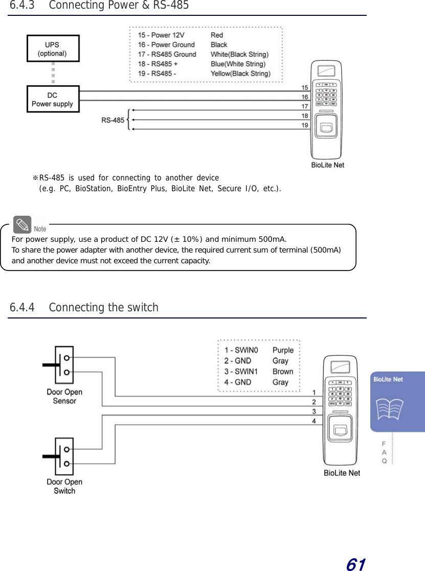
![14 [In case of configuring the network via RS-485] 1. Connect the terminal to the computer that has the dedicated PC software or to another device according to the network environment after seeing “6.4.3 Connecting Power & RS-485.” 2. Configure the settings for RS-485 according to the installation environment. Device In/OutItem Serial Conn. In/Out The completion message window appears. Completed Use / buttons to◀▶ select 115200 for PC connection speed and press OK. Use / buttons to◀▶ select Not Use for termination and press OK. Baudrate 115200 Serial Conn. Type PC Conn. Serial Conn. Termination Not Use Serial Conn. Use / buttons to select the Device icon and press OK. Use / buttons to select the PC Conn. and press OK. Use / buttons to select the In/Out icon and press OK. Use / buttons to select the Serial Conn. and press OK.](https://usermanual.wiki/Suprema/BLROC/User-Guide-1105454-Page-14.png)