User manual

2
This manual is provided for information purpose only. All information included
herein is subject to change without notice. Suprema is not responsible for any
changes, direct or indirect, arising from or related to us of this manual.
ⓒ Copyright 2008 Supremainc. All rights reserved.
3
Contents
Contents ..................................................................................................................... 3
Safety Instructions .................................................................................................... 5
1. Before Use ............................................................................................................. 6
1.1 Components ..................................................................................................................... 6
1.2 Body.................................................................................................................................. 7
1.3 Methods for fingerprint input ............................................................................................. 8
1.4 System setup procedure ................................................................................................. 10
1.4.1 Registering the initial administrator .......................................................................... 11
1.4.2 Network configuration............................................................................................... 12
1.4.3 Stand-alone configuration ........................................................................................ 15
1.4.4 Configuring Secure I/O ............................................................................................. 17
1.4.5 Configuring environment settings ............................................................................. 18
1.5 Authorization methods .................................................................................................... 19
1.5.1 Finger Only ............................................................................................................... 19
1.5.2 Finger or PIN ............................................................................................................ 20
1.5.3 Finger and PIN ......................................................................................................... 23
1.5.4 PIN Only ................................................................................................................... 24
1.5.5 Card Only ................................................................................................................. 25
2. User Management................................................................................................ 26
2.1 Enrolling a user ............................................................................................................... 26
2.2 Editing a user data .......................................................................................................... 28
2.3 Deleting a user data ........................................................................................................ 31
3. Configuration for Screen and Sound ................................................................. 32
3.1 Date, Time ...................................................................................................................... 32
3.2 Backlight ......................................................................................................................... 33
3.3 Sound ............................................................................................................................. 34
4. Device Configuration .......................................................................................... 35
4.1 Authorization ................................................................................................................... 35
4.2 In/Out .............................................................................................................................. 40
4.3 System ............................................................................................................................ 47
5. Attendance Management .................................................................................... 51
5.1 Operating environment ................................................................................................... 51
5.2 Setup for attendance management ................................................................................ 52
5.3 Operation modes ............................................................................................................ 53
5.3.1 Key Input .................................................................................................................. 53
5.3.2 Manual ...................................................................................................................... 53
5.3.2 Auto .......................................................................................................................... 54
5.3.3 Fixed ......................................................................................................................... 55
6. FAQ ....................................................................................................................... 56
6.1 Error messages .............................................................................................................. 56
6.2 Troubleshooting .............................................................................................................. 57
6.3 Usage summary.............................................................................................................. 58
6.4 System Installation .......................................................................................................... 59
4
6.4.1 Cable specifications ................................................................................................. 59
6.4.2 Installing the bracket ................................................................................................ 60
6.4.3 Connecting Power & RS-485 ................................................................................... 61
6.4.4 Connecting the switch .............................................................................................. 61
6.4.5 Connecting the relay ................................................................................................ 62
6.4.6 Connecting Network ................................................................................................ 63
6.4.7 Connecting Wiegand ............................................................................................... 63
6.4.8 Electrical specifications ............................................................................................ 64
6.5 Specifications ................................................................................................................. 65
6.6 FCC Notice ..................................................................................................................... 67
5
Safety Instructions
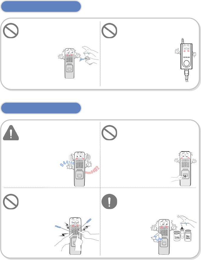
Installation
In Use
Do not arbitrarily install or
repair the product.
The warranty does not apply to
any product damage
caused by an
arbitrary
installation or
repair.
Use the power adapter
provided or one for 12V 0.5A
or above.
Endure that password does
not exposed to unauthorized
individuals. Frequent change
of password is
recommended.
Any illegal access to
your product may
ha
pp
en.
Be cautioned for the
fingerprint contact area not
to be contaminated or
damaged by dirty hands or
foreign materials.
It may affect fingerprint
recognition performance
or cause a failure.
Do not forcibly press the
buttons of the product and
avoid any contact with sharp
object to the device.
It may cause
a failure.
Do not clean the device with
any form of liquid. Use soft
and dry cloth only.
When sharing the power with
other devices such as electric
door lock, check the power
capacity considering power
requirements for each device.
If appropriate power is not used,
it may not operate normally.
6
1. Before Use
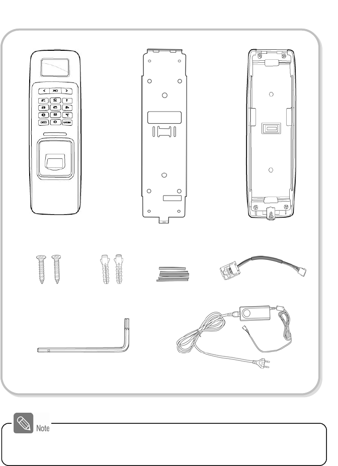
1.1 Components
Main Body Wall mounting bracket Extended bracket
(Option)
Fixing Screws
(2 EA)
Knife Blocks
(2 EA)
Star-shape wrench
(For fixing bracket)
Adapter
(Option)
Shrinkable
Tubes
Ethernet Connecto
r
The components shown above may differ depending on the installation
environment.
7
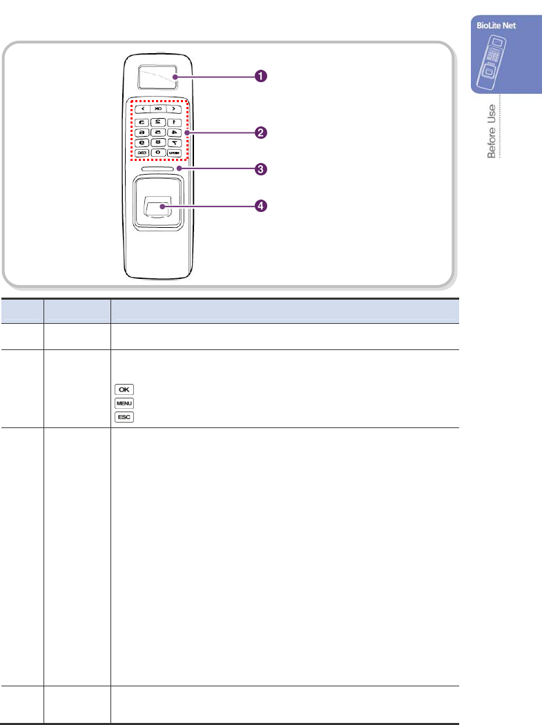
1.2 Body
No. Name Description
1 LCD Display The operation status is displayed.
2 Key Pad 0–9 Buttons: Used to enter the ID and password.
< > Arrow Buttons: Used to move the selected item.
Button: Used to select the desired function.
Button: Used to enter or exit the menu.
Button: Used to exit from the menu or cancel the desired action.
3 LED Lamp The operation status is displayed with an alert sound.
– Green (Sound: beep beep beep beep!): Authorization success
– Red (Sound: beep beep beep!) : Authorization failure
– Pink (Sound: beep!) : Processing
– Blue and Yellow blink in turn at an interval of 2 seconds (No sound): No IP
address is given because DHCP is set in TCP/IP Setup
– Blue and Sky Blue blink in turn at an interval of 2 seconds (No sound): Normal
operation
– Red and Pink blink in turn at an interval of 2 seconds (No sound): Device locked
or no administrator
– Blue and Red blink in turn at an interval of 2 seconds (No sound): The time is
reset due to battery discharge.
– At first use, Red blinks at an interval of 2 seconds (No sound): Initialization
error, Consult with the manufacturer.
– In normal use, Red blinks at an interval of 2 seconds (No sound): On the
watch.
– Yellow blinks shortly (No sound): Entry standby or in communication for
getting an IP when DHCP is set in TCP/IP Setup
4 Fingerprint
Touch Area Used to input a fingerprint for authentication.
LCD Displa
y
LED Lamp
Fin
g
erprint Touch Area
Ke
y
Pad
8
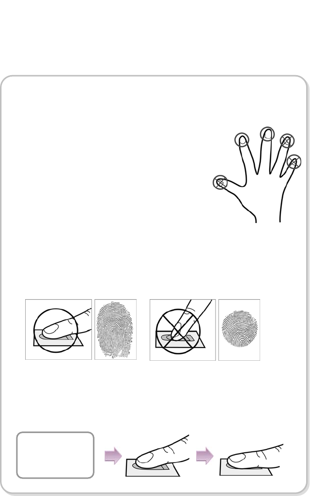
1.3 Methods for fingerprint input
BioLite Net can easily recognize fingerprints even though the angle and
location of the pattern change. However, it is recommended to properly
input fingerprints for more precise recognition.
Selecting a finger on fingerprint enrollment
How to proerply place a fingerprint
Place your finger firmly on the sensor area.
Adjust the finger so that its middle position can be located in the center
of the sensor.
When the finger is vertically placed or its angle goes astray, the
recognition may be a failure.
Up to two fingerprints can be enrolled for each user in preparation of
any abnormal situation like having a wounded finger or carrying an
object with a hand.
In the case of a low recognition, the user can register
the same fingerprint twice to increase the recognition
rate.
It is recommended to use the index or middle finger.
In case of other fingers, the recognition rate
decreases because it tends to be more difficult to
place the finger in the center of the sensor area.
Place the first
Fin
g
e
r
When enrolling your fingerprint, the first finger input window prompts.
Then register the desired finger on the terminal as shown in the figure
below.
When the re-entry window appears with a “tick” sound, re-enter the
previously enrolled finger. The fingerprint input is made twice.
(Gently push your finger on the sensor to have a full fingerprint.)
9
In case fingerprint is not recognized normally
Cautions while registering your fingerprint
BioLite Net is designed to normally operate regardless of weather change or the
angle and location of the fingerprint to place.
However, the recognition rate may vary depending on the external environment or
fingerprint condition.
In abnormal cases, follow the directions below:
1. Retry after drying the wetness of your finger.
2. When your finger is too dry, retry after blowing on your fingertip.
3. When you have a cut on your registered finger, register another fingerprint.
The initial fingerprint registration is important.
Because the recognition process compares the scanned fingerprint with the
registered one, an abnormally registered fingerprint can cause a failure.
To increase the recognition rate, follow the directions below:
1. Put the center of your fingerprint on the middle of the sensor.
2. If you have a cut in your finger or your fingerprint is not clear enough, retry with
another finger.
3. When fingerprint recognition is in progress, do not move your fingerprint .
10
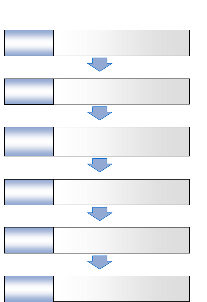
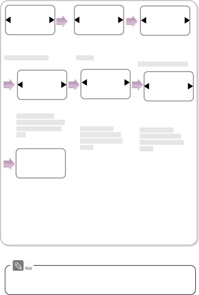
1.4 System setup procedure
Install the system according to the environment
- Grasp the locations for installation site, door open switch,
dead bolt, and such.
- Install the system (see 6.4).
Step 1
Register users
- Use the system after user registration (see 2.1).
Step 6
Register an initial administrator
- Register the initial administrator for setting devices (See 1.4.1).
Step 2
Configure the environment
- Configure various environments (see 1.4.5).
Step 5
Test for system operation
- Check the door lock/unlock status and switch operation.
- Deliver the setting items to the customer.
Step 4
- Network configuration (see 1.4.2)
- Stand alone configuration (see 1.4.3.) or
Secure I/O configuration (see 1.4.4)
Step 3 Configure the system
11
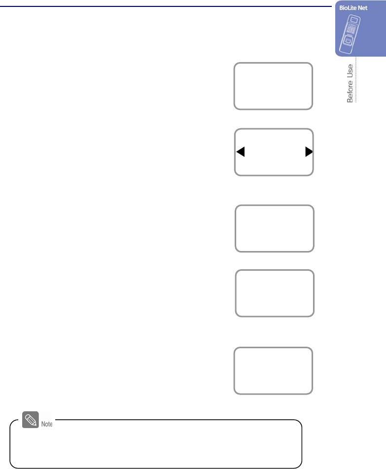
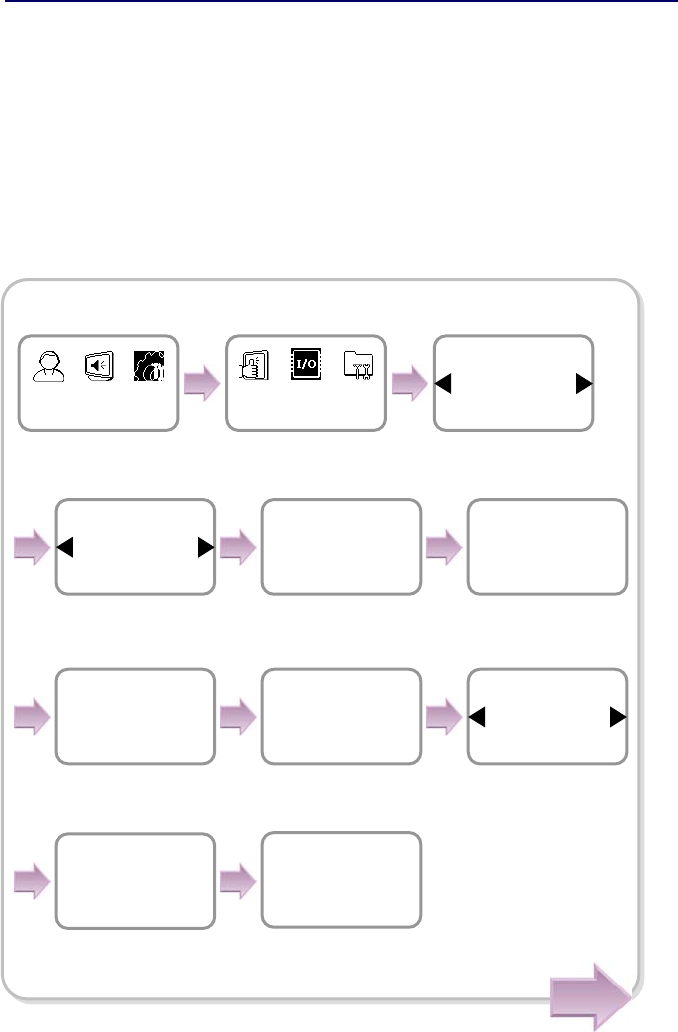
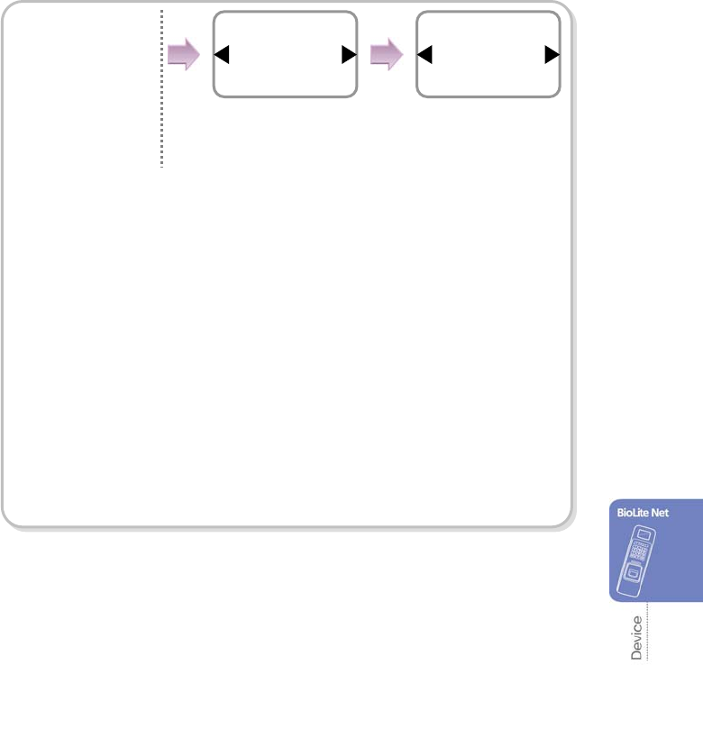
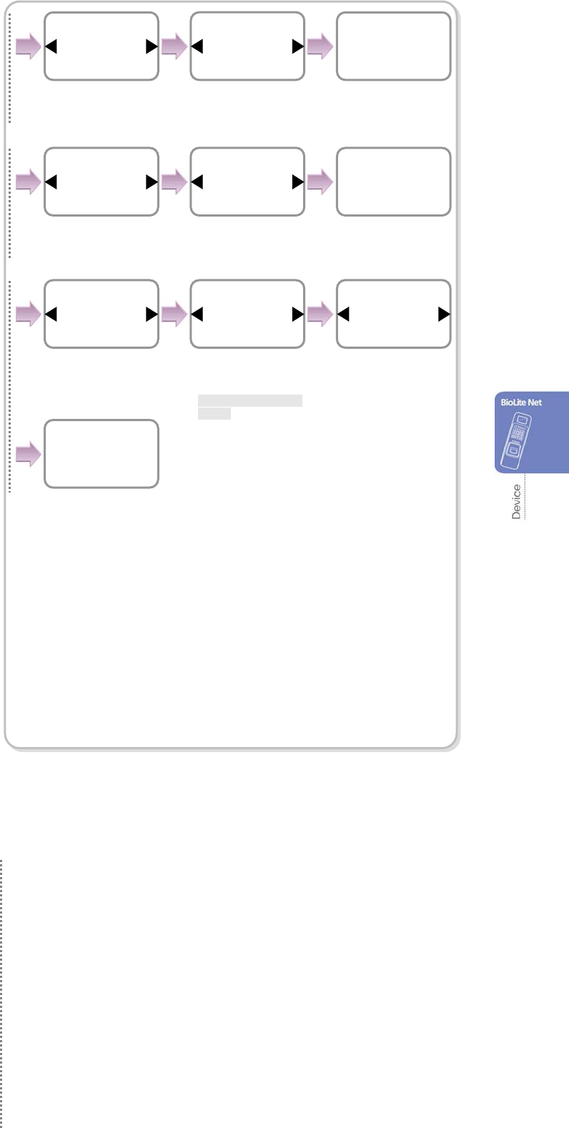
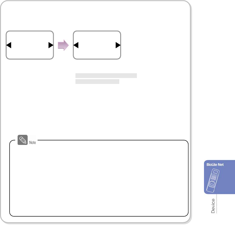
1.4.1 Registering the initial administrator
There is no administrator set for the product in the initial status. So register an
administrator for configuring the environments for relay, door open switch, door open
detection sensor, and such.
1. When the product is connected, a window
appears as shown in the right figure. Enter an ID
and press OK.
2. When the authorization mode window appears,
use / buttons to move to PIN Only, and
press OK.
3. When the password entry window appears, enter
the desired password and press OK.
4. When the password re-entry window appears,
enter the previously input password again and
press OK.
5. The completion message window appears.
Operation Mode
PIN Only
Enroll
Enter PIN
****
Enroll
Confirm PIN
****
Enroll
Completed
This procedure is necessary to temporarily configure the installation-
related settings. Modify the administrator information after the
installation is complete.
Enter ID
1
Enroll Admin
12
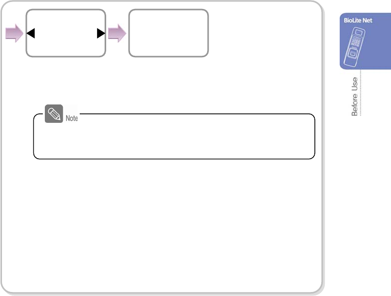
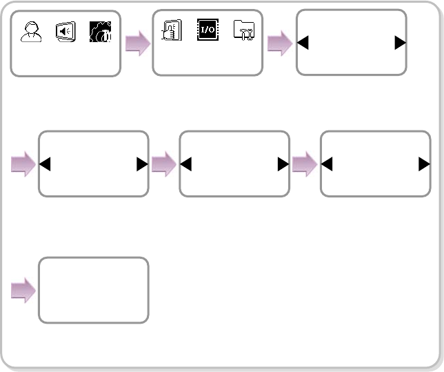
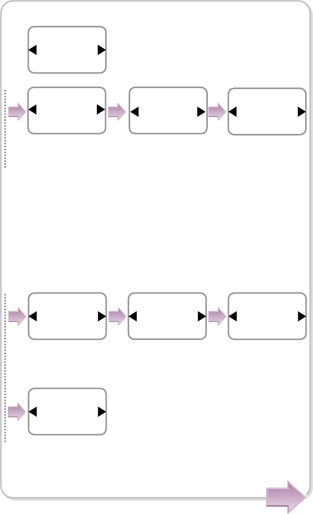
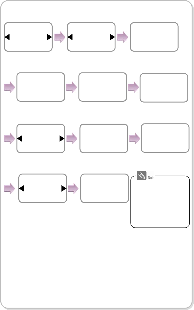
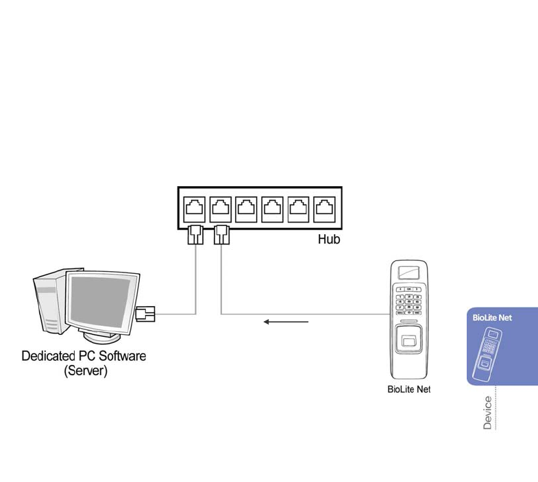
1.4.2 Network configuration
The network configuration is required to connect the dedicated PC software or other
devices via network. Configure the settings according to the communication
environment in your place.
[In case of configuring the network via Ethernet]
1. Connect the terminal to the computer that has the dedicated PC software according
to the network environment after seeing “6.4.6 Connecting network.”
2. Configure the settings for TCP/IP port and server according to the installation
environment.
Use / buttons to set
whether or not to use
DHCP and press OK.
Server IP
192.168.1.30
TCP/IP
Server Port
1480
TCP/IP
Subnet Mask
255.255.255.0
TCP/IP
Server
Use
TCP/IP
Port
1471
TCP/IP
Item
TCP/IP
In/Out
Device In/Out
DHCP
Not Use
TCP/IP
IP Address
192.168.1.35
TCP/IP
Gateway
192.168.1.10
TCP/IP
※ The following example explains how to directly connect the server PC without
usin
g
DHCP.
Use / buttons to
select the Device icon
and press OK.
Use / buttons to
select the In/Out icon
and press OK.
Use / buttons to
select the TCP/IP and
press OK.
Enter the IP address
and
p
ress OK.
Enter Port and
press OK.
Enter Server Port
and press OK.
Enter the Gateway using
numeric and arrow
buttons and press OK.
Enter Server IP address
using numeric and arrow
button and press OK.
Enter IP address using
numeric and arrow button
and press OK.
Use / buttons
to select the Use
and press OK.
Cont.
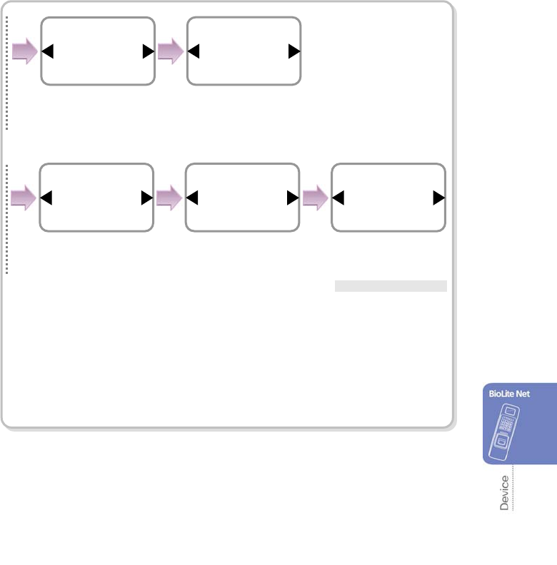
13
※IP Address/Gateway/Subnet Mask Setup: If DHCP is used, the values for
IP address, gateway, and subnet mask are automatically assigned. Otherwise, set DHCP
to Not Use and enter the corresponding values.
(When the right arrow is pressed, “.” is entered while the left arrow deletes characters
one by one.)
※Server: To directly connect the server of the dedicated PC software that enables
monitoring and setting the terminal, use Server for its setup and enter the values for
IP address and port number. (Refer to the dedicated PC software manual.)
※TCP/IP Port, Server Port: Should be the same values defined in the dedicated
PC software. It is recommended to set the TCP/IP port to “1471” and Server to “1480.”
(When the port number is modified as you want, TCP/IP communication may not be active.)
The completion
message window
appears.
Use / buttons to
set whether or not to
support 100Base-T
and press OK.
Completed
100Base-T support
Not support
TCP/IP
When you exit from the menu before completing the TCP/IP
setting, the data is not stored so please finish the remaining
steps until the setting completion message appears.
14
[In case of configuring the network via RS-485]
1. Connect the terminal to the computer that has the dedicated PC software or to
another device according to the network environment after seeing “6.4.3 Connecting
Power & RS-485.”
2. Configure the settings for RS-485 according to the installation environment.
Device In/Out
Item
Serial Conn.
In/Out
The completion message
window appears.
Com
p
leted
Use / buttons to◀▶
select 115200 for PC
connection speed and
press OK.
Use / buttons to◀▶
select Not Use for
termination and press
OK.
Baudrate
115200
Serial Conn.
Type
PC Conn.
Serial Conn.
Termination
Not Use
Serial Conn.
Use / buttons to
select the Device icon
and press OK.
Use / buttons to
select the PC Conn.
and press OK.
Use / buttons to
select the In/Out icon
and press OK.
Use / buttons to
select the Serial Conn.
and press OK.
15
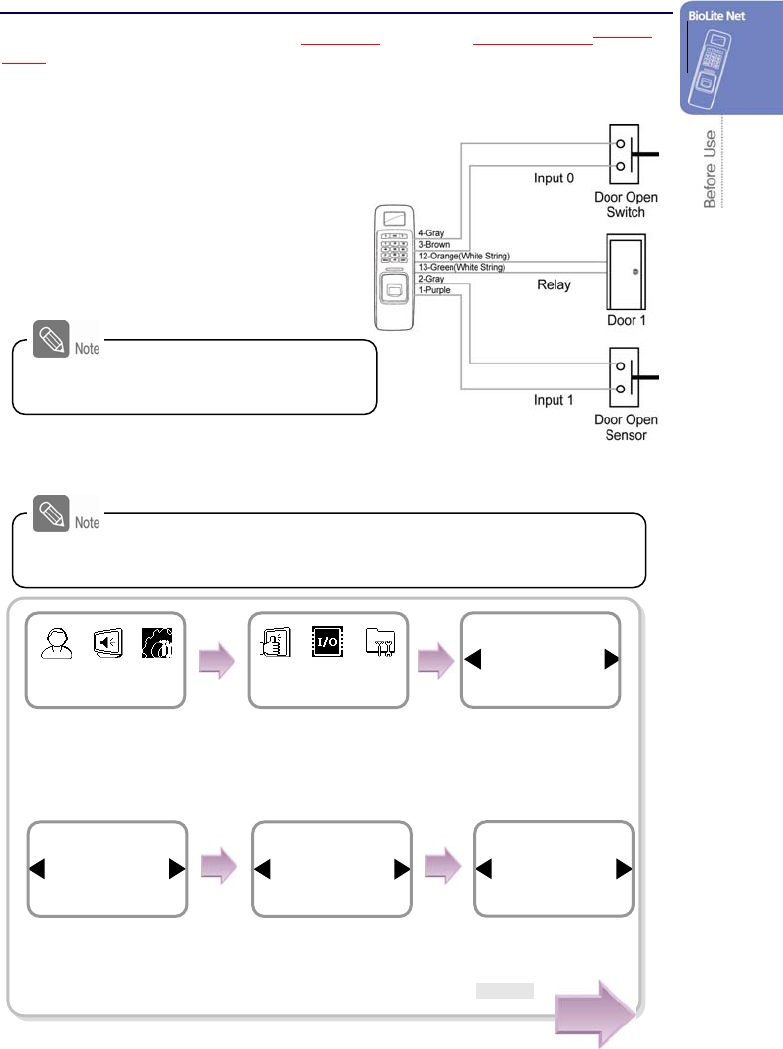
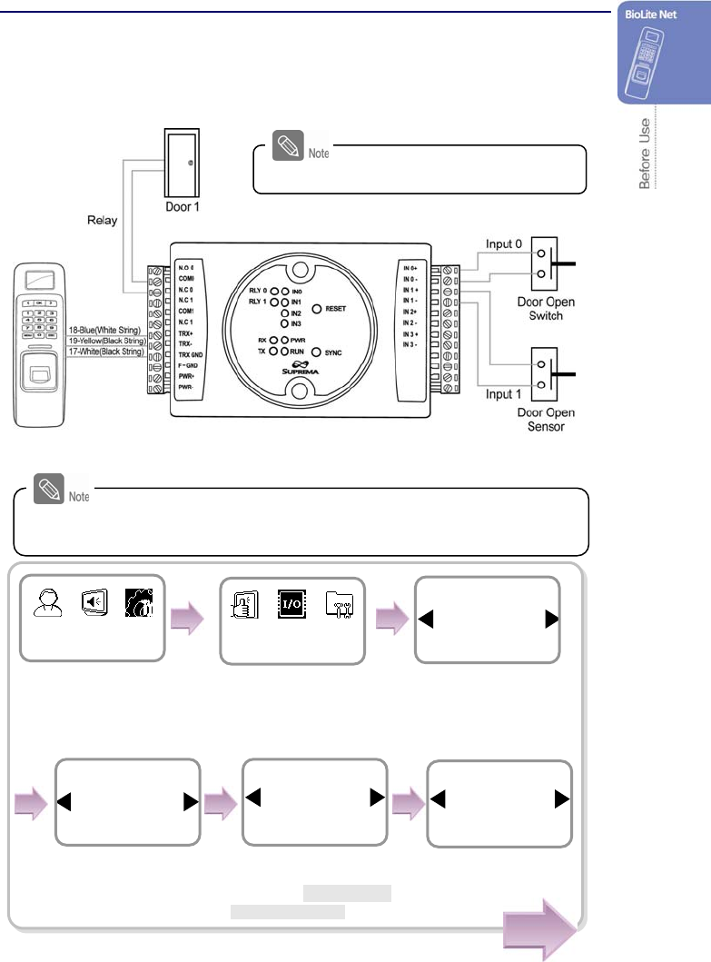
1.4.3 Stand-alone configuration
This configuration is required to use the device for stand alone purpose, which device
which requires no communication with PC or other devices.
1. As shown in the figure, connect BioLite Net to respective switches.
2. Configure the internal relay settings as shown below. (It is explained based on the
figure above.)
For actual wring method,
see “6.4 System Installation.”.
Follow the instructions below only when the dedicated PC software is not
used. When using the software, refer to the software manual.
Use / buttons to
select Internal and
press OK.
Use / buttons to
select Input 0 and press
OK.
Use / buttons to
select N.O and press
OK.
*N.O/N.C
Relay
Internal
Door
Exit Button
Input 0
Internal
Type
N.O
Exit Button
Use / buttons to
select the In/Out icon
and press OK.
Press MENU -> Enter ID
-> Enter the password ->
Use / buttons to
select the Device icon and
press OK.
Use / buttons to
select Door and press
OK.
Device
In/Out
Item
Door
In/Out
Cont.
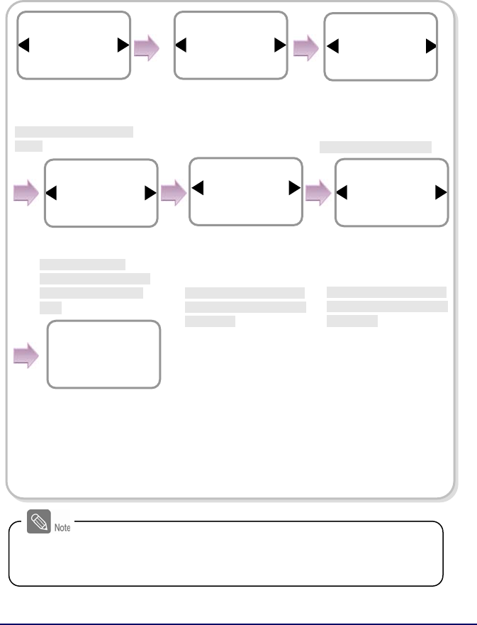
16
※
Opening Mode
-
Temporary Open
: When the door is open, it is automatically closed after a specific time.
- Toggle: The door is open after the first authorization success and it remains unlocked
until the second authorization success.
Enter the time and
press OK.
*The time is set for
automatically closing the
door after the specified
time.
Use / buttons to
select Not Use for
Held
Open Alarm
and press
OK.
*Not Use/Sound/
Backlight/Sound and
Light/SIO Relay0/SIO
Relay1
Door Sensor
Input 1
Internal
Held Open Alarm
Not Use
Door
Use / buttons to
select N.O and press
OK.
*N.O/N.C
Use / buttons to
select Input 1 and press
OK.
*Not Use/Input0/Input1
Use / buttons to
select Temporary Open
for opening mode and
press OK.
* Temporary Open/ Toggle
Opening Mode
Temporary Open
Door
Type
N.O
Door Sensor
Open Time
3
Door
Use / buttons to
select Not Use for
Forced Open Alarm and
press OK.
*Not Use/Sound/
Backlight/Sound and
Light/SIO Relay0/ SIO
Relay1
The completion
message window
appears.
Forced Open Alarm
Not Use
Door
Complete
When you exit from the menu before completing the relay setup, the
configuration is not stored so please finish configuration until the
message “Complete” appears.
17
Cont.
1.4.4 Configuring Secure I/O
This connects BioLite Net to Secure I/O.
1. Connect wires between BioLite Net, Secure I/O, and respective switches as shown
below.
2. Configure the relay settings as shown below. (Based on the figure above)
For actual wiring, see “6.4 System Installation.”
Follow the instructions below only when the dedicated PC software is not
used. When using the software, refer to the software manual.
Use / buttons to
select SIO Relay 0 and
press OK.
Use / buttons to
select SIO Relay 0 and
press OK. (*Not Use/ SIO
Input 0/ SIO Input 1)
Relay
SIO Relay 0
Door
Exit Button
SIO Input 0
SIO Relay 0
Use / buttons to
select N.O and press
OK.
Type
N.O
Exit Button
Device
In/Out
Use / buttons to
select the In/Out icon
and press OK.
Press Menu -> Enter ID ->
Enter password ->Use /
buttons to select the
Device icon and press OK.
Item
Door
In/Out
Use / buttons to
select Door and press
OK.
18
※Opening Mode
-Temporary Open: When the door is open, it is automatically closed after a specific time.
-Toggle: The door is opened after the first authorization success and it remains unlocked
until the second authorization success.
1.4.5 Configuring environment settings
Settings for date and time: Set the values as “3.1 Date, Time.”
Fingerprint authorization related settings: Set the values after reading the case of
fingerprint selection in “4.1 Authorization.”
Operation mode setting: Finish the setting after seeing the operation mode
selection case in “4.1 Authorization.”
※Sync. Button
(In case of using Secure I/O)
Sync. button should be pressed when Relay
setting is completed.
Enter the time and
press OK.
*The time is set for
automatically closing the
door after the specified
time.
Use / buttons to
select Not Use for Held
Open Alarm and press
OK.
*Not Use/Sound/Backlight/
Sound & Light/SIO Relay0/
SIO Relay1
Door Sensor
SIO Input 1
SIO Relay 0
Held Open Alarm
Not Use
Door
Use / buttons to
select N.O and press
OK.
Use / buttons to
select SIO Input 1 and
press OK.
*Not Use/ SIO Input0/ SIO
Input1
Opening Mode
Temporary Open
Door
Use / buttons to
select Temporary Open
for opening mode and
press OK.
* Temporary Open/Toggle
Type
N.O
Door Sensor
Open Time(sec)
3
Door
Use / buttons to
select Not Use for
Forced Open Alarm and
press OK.
*Not Use/Sound/Backlight/
Sound & Light/SIO Relay0/
SIO Relay1
The completion message
window appears.
Forced Open Alarm
Not Use
Door
Complete
When you exit from the menu before completing the relay setup, the
configuration is not stored so please finish configuration until the
message “Complete” appears.
19
1.5 Authorization methods
For changing the terminal authorization method, see the operation mode selection case
in “4.1 Authorization.”
To separately set the authorization method for each user, see “2.2 Editing a user data.”
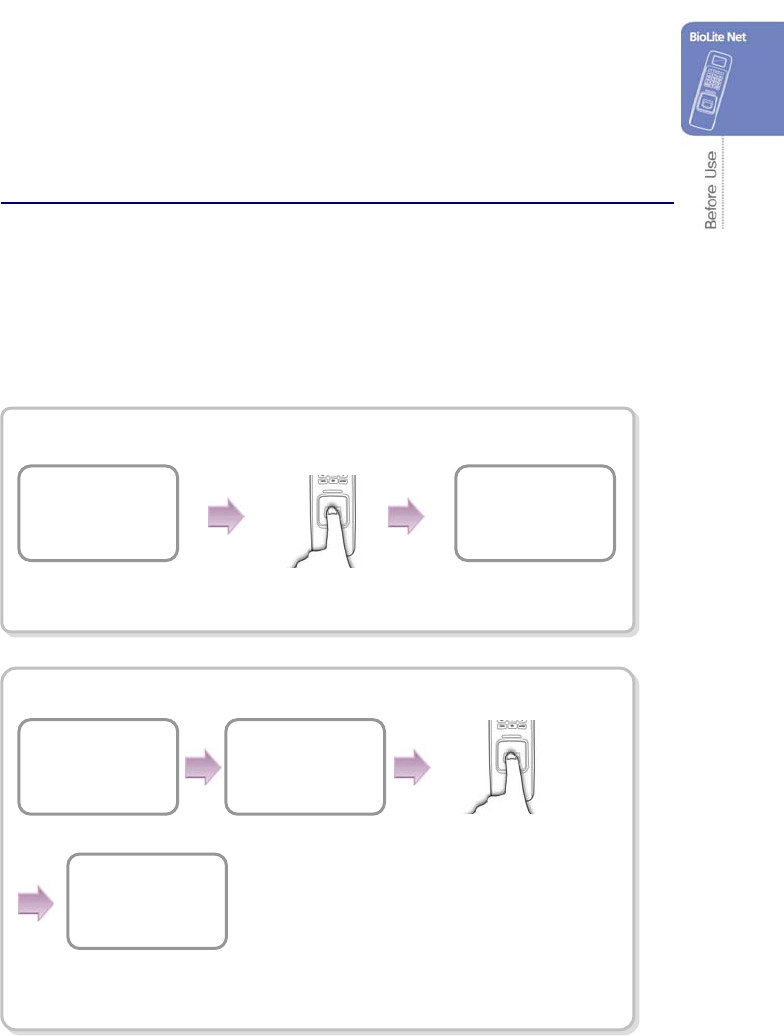
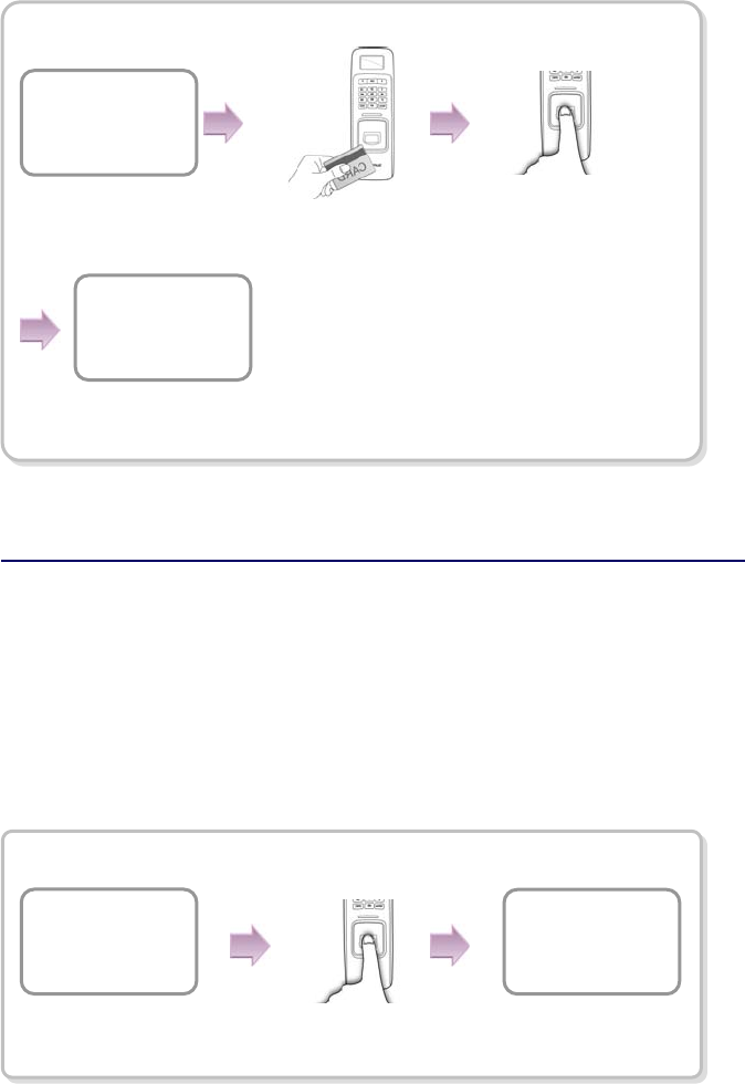
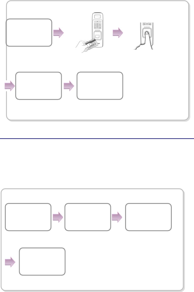
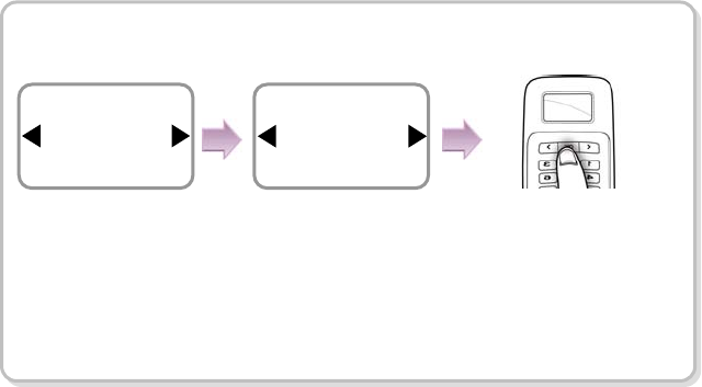
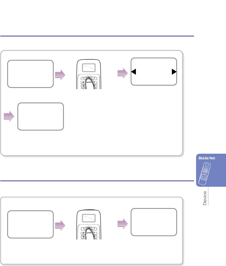
1.5.1 Finger Only
When the user authorization method is set to “Finger Only,” you can open the door by
using the three different methods:
1. Fingerprint recognition
2. Fingerprint recognition after entering ID
3. Fingerprint recognition after identifying user card
Fingerprint recognition
Fingerprint recognition after entering ID
Input the fingerprint of
the user.
The door is open with
the authentication
success messa
g
e.
A
ccess Granted
ID : 2
BioLite Net
10:33:02
BioLite Net
10:33:02
Enter ID
2
Input the fingerprint
of the user.
The door is open with
the authentication
success message.
A
ccess Granted
ID : 2
Enter the ID of the
user and press OK.
20
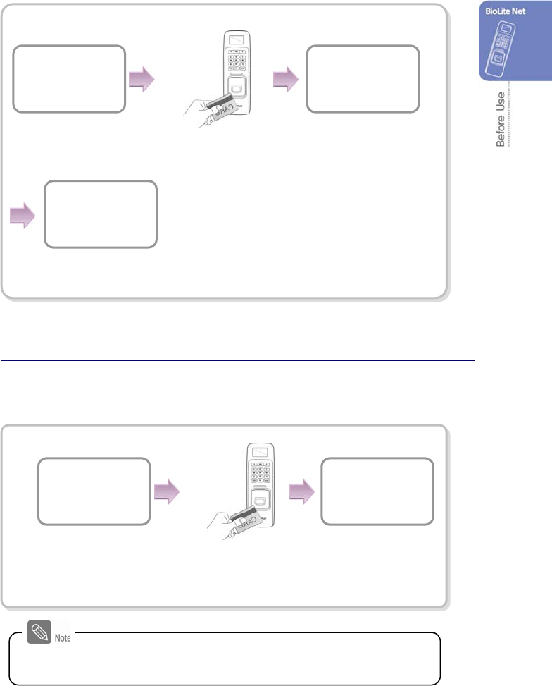
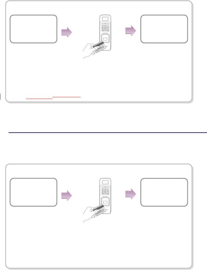
Fingerprint recognition after identifying user card
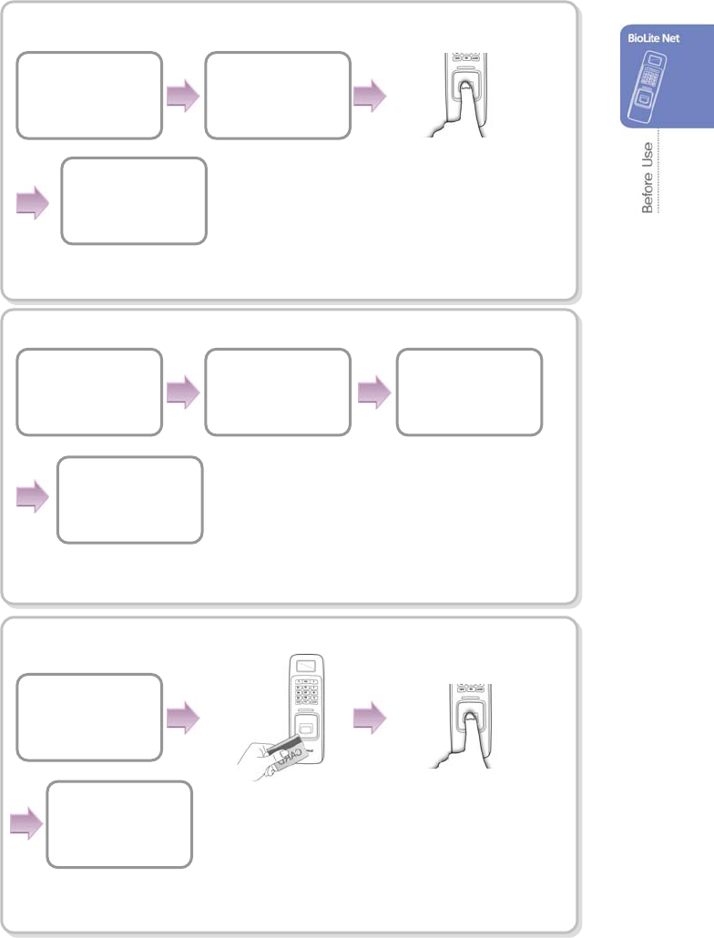
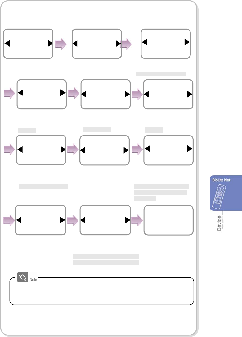
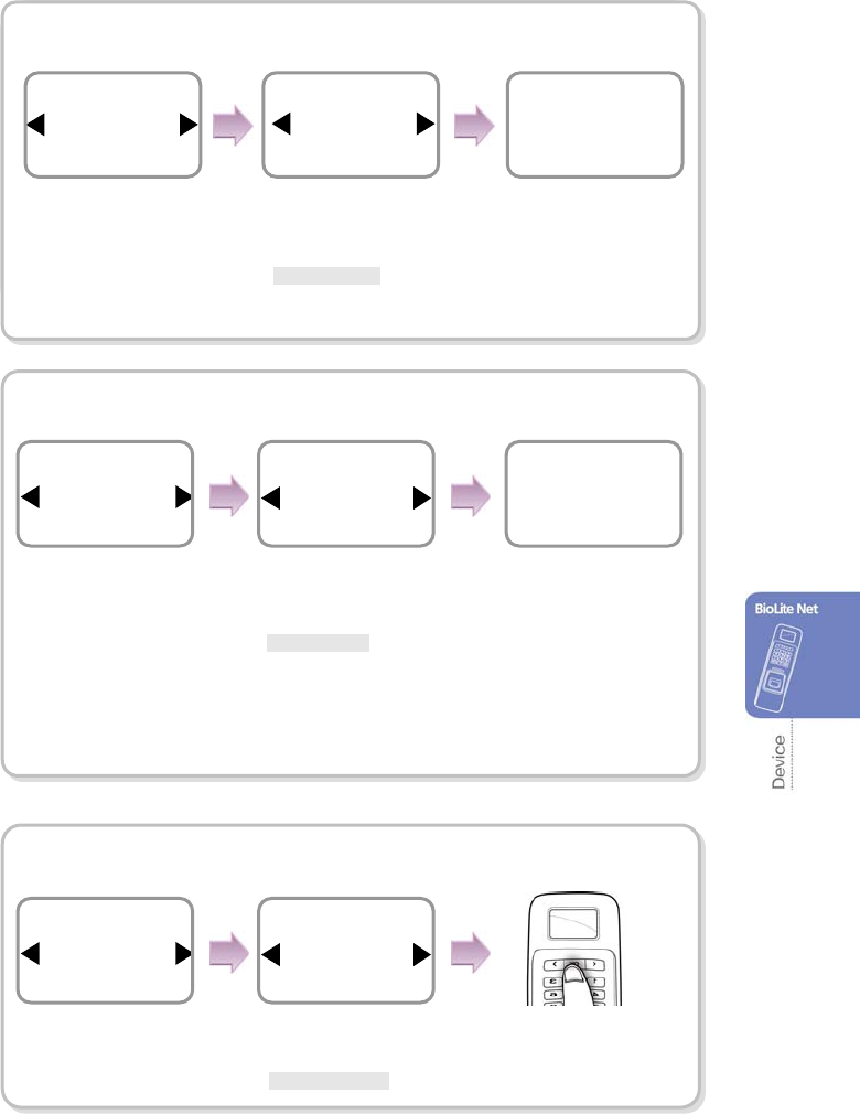
1.5.2 Finger or PIN
When the user authorization method is set to “Finger or PIN,” you can open the door by
using the five different methods:
1. Fingerprint recognition
2. Fingerprint recognition after entering ID
3. Password entry after entering ID
4. Fingerprint recognition after identifying the user card
5. PIN entry after identifying the user card
Fingerprint recognition
Input the fingerprint
of the user.
The door is open with
the authentication
success messa
g
e.
A
ccess Granted
ID : 2
BioLite Net
10:33:02
BioLite Net
10:33:02
Input the fingerprint
of the user.
The door is open with the
authentication success message.
A
ccess Granted
ID : 2
Place the user card on the
SUPREMA logo area.
21
Fingerprint recognition after entering ID
PIN entry after entering ID
Fingerprint recognition after identifying user card
Enter Fin
g
er or PIN
****
BioLite Net
10:33:02
Enter ID
2
Input the fingerprint of
the user.
The door is open with the
authentication success
message.
A
ccess Granted
ID : 2
BioLite Net
10:33:02
Enter ID
2
The door is open with
the authentication
success message.
A
ccess Granted
ID : 2
BioLite Net
10:33:02
Input the fingerprint
of the user.
The door is open with the
authentication success
message.
Access Granted
ID : 2
Place the user card on the
SUPREMA logo area.
Enter the password
of the user and
press OK.
Enter the ID of the
user and press OK.
Enter the ID of the
user and press OK.
22
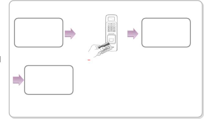
PIN entry after identifying the user card
BioLite Net
10:33:02
The door is open with
the authentication
success message.
A
ccess Granted
ID : 2
Place the user card on the
SUPREMA logo area.
Enter Fin
g
er or PIN
****
Enter the password
of the user and
press OK.
23
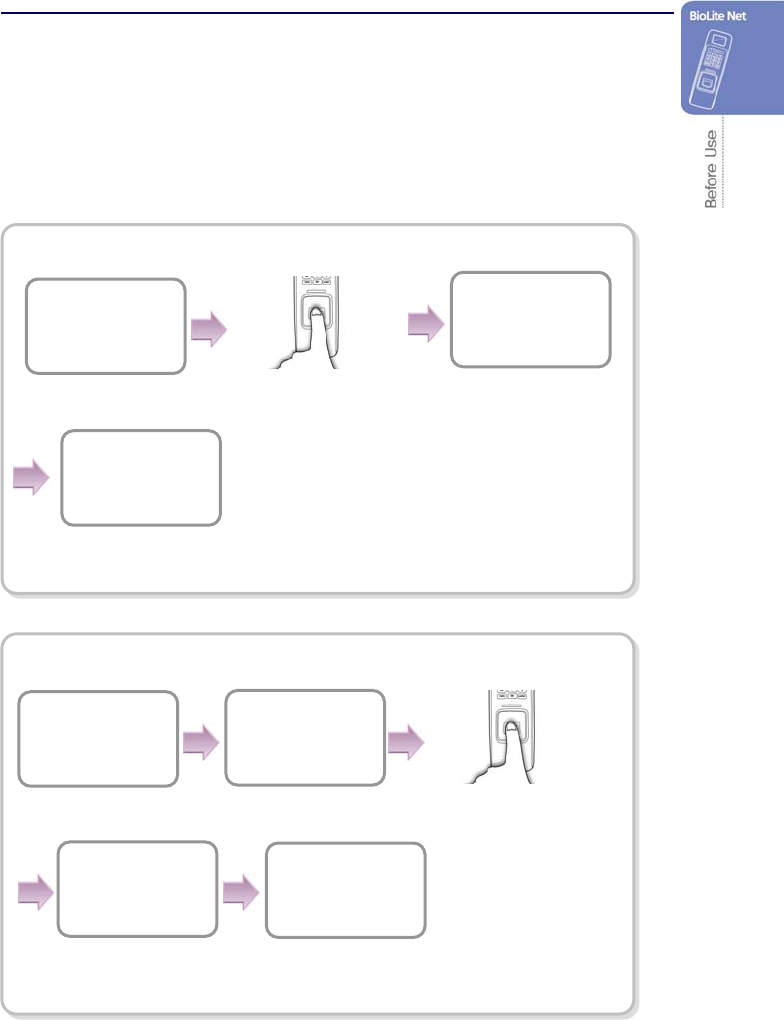
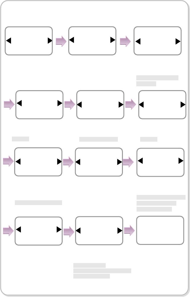
1.5.3 Finger and PIN
When the user authorization method is set to “Finger and PIN,” you can open the door
by using the three different methods:
1. PIN entry after identifying fingerprint
2. PIN entry after entering ID and fingerprint
3. PIN entry after entering user card and fingerprint
PIN entry after identifying fingerprint
PIN entry after entering ID and fingerprint
The door is open with the
authentication success
message.
Access Granted
ID : 2
Enter PIN
****
BioLite Net
10:33:02
Input the fingerprint
of the user.
BioLite Net
10:33:02
Enter ID
2
The door is open with
the authentication
success message.
A
ccess Granted
ID : 2
Enter PIN
****
Input the fingerprint
of the user.
Enter the password
of the user and
press OK.
Enter the password
of the user and
press OK.
Enter the ID of the
user and press OK.
24
PIN entry after entering user card and fingerprint
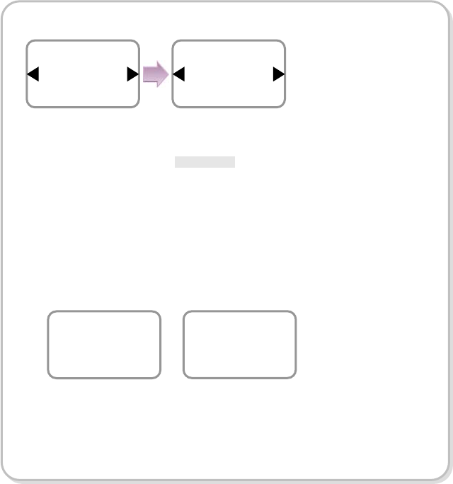
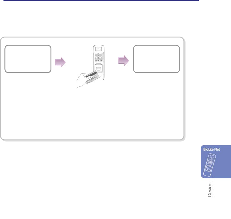
1.5.4 PIN Only
When the user authorization method is set to “PIN Only,” you can open the door by
using the two different methods:
1. PIN entry after entering ID
2. PIN entry after identifying user card
PIN entry after entering ID
BioLite Net
10:33:02
The door is open with the
authentication success message.
A
ccess Granted
ID : 2
Place the user card on the
SUPREMA logo area.
Enter PIN
****
A
ccess Granted
ID : 2
Input the fingerprint
of the user.
The door is open with the
authentication success message.
Enter the password
of the user and
press OK.
Enter the password
of the user and
press OK.
Enter the ID of the
user and press OK.
Enter Fin
g
er or PIN
****
BioLite Net
10:33:02
Enter ID
2
25
PIN entry after identifying user card
1.5.5 Card Only
When the user authorization method is set to “Card Only,” you can open the door by
following the instructions below:
Place the user card on the
SUPREMA logo area.
BioLite Net
10:33:02
A
ccess Granted
ID : 2
Place the user card on the
SUPREMA logo area.
Enter Fin
g
er or PIN
****
BioLite Net
10:33:02
For “Card Only,” register the card user on the dedicated PC software
first.
The door is open with the
authentication success message.
The door is open with
the authentication
success message.
Enter the password
of the user and
press OK.
A
ccess Granted
ID : 2
26
2. User Management
The user management and other environment settings can be updated after authorizing
the registered administrator (see “1.4.1 “Registering the initial administrator”).
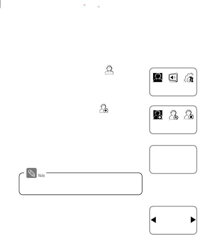
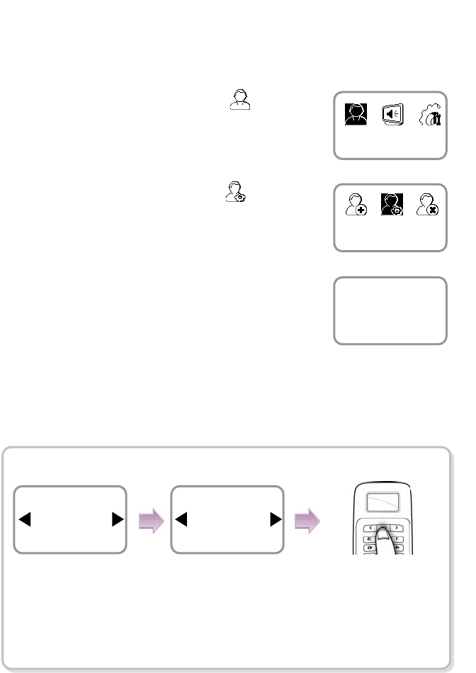
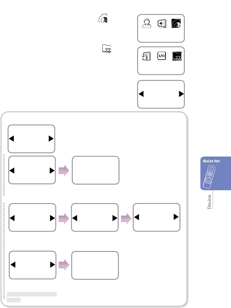
2.1 Enrolling a user
You can enroll a new user as shown below:
1. Use / buttons to select the User ( ) icon
and press OK.
2. Use / buttons to select Enroll ( ) icon and
press OK.
3. The ID that can be used appears. Use it or enter
another ID and press OK.
(1–8 digit number)
4. Use / buttons to select Level and press
OK.
(Level: General /Administrator)
※The user enrollment and environment configuration
are enabled only in Administrator level.
User
Enroll
Enter ID
3
Enroll
Level
General
Enroll
ID is used to edit or delete the user data so
please keep it carefully.
27
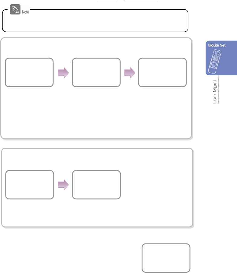
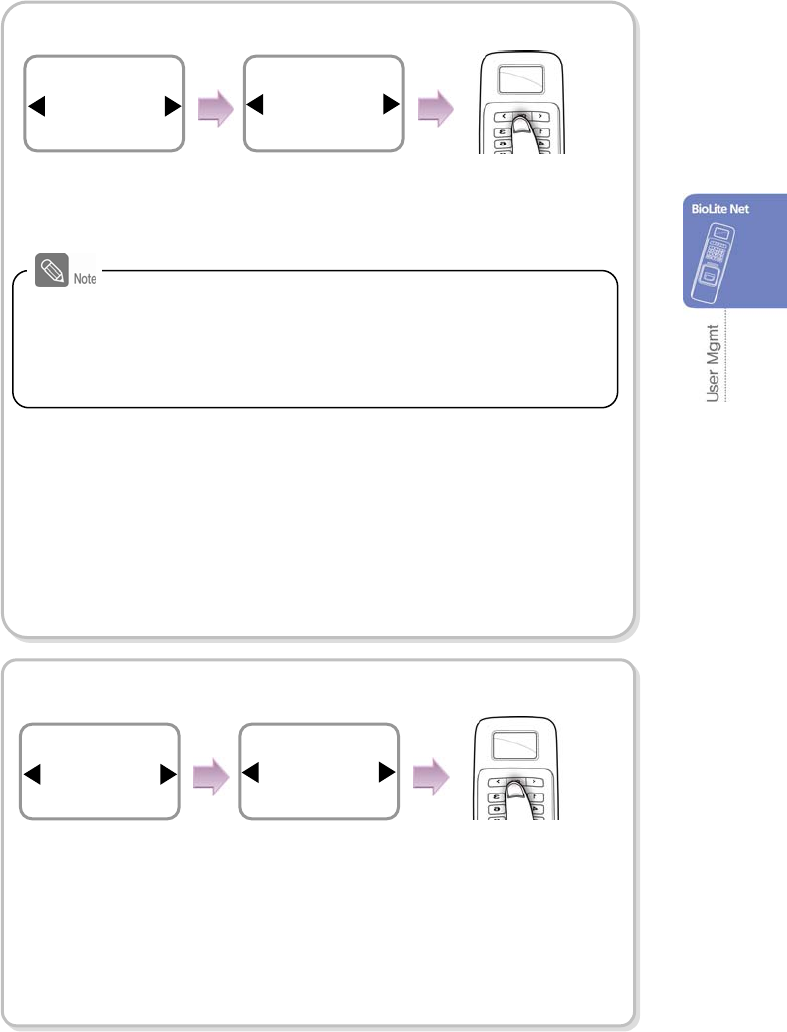
5. Enter the finger or PIN depending on the operation mode.
(Password: 4–8 digit number, Fingerprint: 1st finger or 1st + 2nd fingers)
Finger Only/Finger or PIN/Finger and PIN
※In order to skip the second fingerprint enrollment after enrolling the first
fingerprint, press ESC.
※The user can enroll one or two fingerprints for passing the door.
PIN Only/ Finger and PIN
※For password, it is recommended to enter 4 to 8 digit number not to be easily
exposed.
6. When the user enrollment is successfully done,
the completion message window appears.
※User can be enrolled up to maximum 5000.
Completed
Enter the required information after selecting Device > Authorization
> Operation Mode > Auth Mode.
Place the first
finger again
Place the first
fin
g
e
r
Place the second
fin
g
e
r
(
Ski
p
=ESC
)
Place the first finger
on the sensor. Place the same finger
on the sensor again. Place the second
finger in the same
manner.
Confirm PIN
*****
Enroll
Enter PIN
*****
Enroll
28
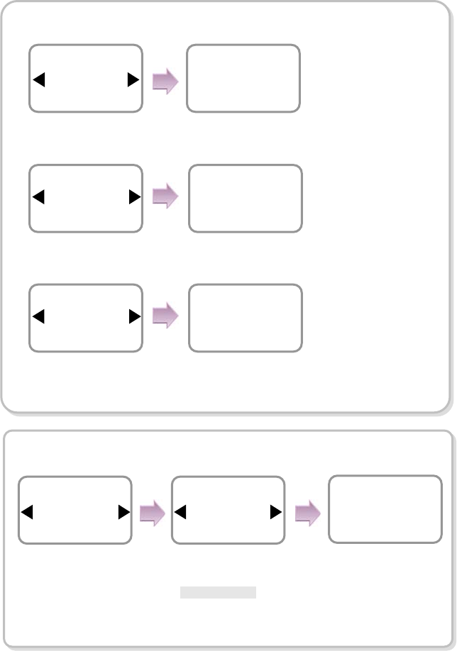
2.2 Editing a user data
You can modify the data of the previously enrolled user.
1. Use / buttons to select the User ( ) icon
and press OK.
2. Use / buttons to select the Edit ( ) icon
and press OK.
3. Enter the ID or fingerprint of the desired user and
press OK.
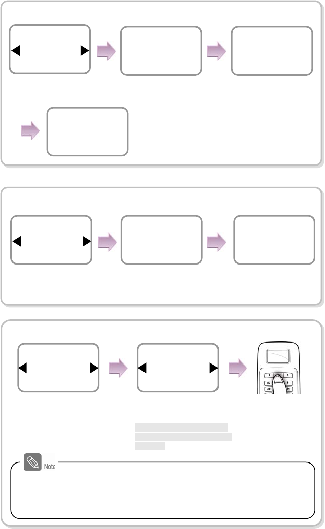
4. Use / buttons to select the desired item and press OK.
※ select any of Level/Operation Mode/Security Level/Finger/PIN/Access Group(1~4)
Changing the user level
※The settings for user, screen/sound, device, and such can be configured
only by the administrator level.
User
Edit
Enter ID/Fin
g
e
r
4
Edit
Item
Level
Edit
Use / buttons
to select Level and
press OK.
Use / buttons
to select General or
Administrator.
Press OK.
Level
General
Edit
29
Changing the authorization method
Autho※rization methods: *Finger Only/PIN Only/Finger or PIN
/ Finger and PIN/Card Only/Per Device
- Finger Only: Only fingerprint is used.
- PIN Only: Only PIN is used.
- Finger or PIN: Fingerprint or PIN is used.
- Finger and PIN: Both fingerprint and PIN are used.
- Card Only: Only user card is used.
- Per Device: The mode set in “Device > Authorization > Operation Mode >
Auth Mode” is used.
Changing the security level of the user
※Security Level: *Per Device/Lower/Low/
Normal
/High/Higher
- Per Device: The security level in “Device>Authorization>Fingerprint>”
on page 37 is applied.
- The higher the security level, the more sensitive the fingerprint recognition.
But the authorization failure rate can increase.
This authorization method setting for each user has higher priority than
the terminal setting that has been defined in Device > Authorization
> Operation Mode > Auth Mode. Note that this function is applied to
the case when the user enters ID or card and when Use is set in
Device > Authorization > Operation Mode > Private Auth
Item
Operation Mode
Edit
Use / buttons to
select Operation Mode
and press OK.
Use / buttons
to select an desired
operation mode and
press OK.
Press OK.
Operation Mode
Finger Only
Edit
Use / buttons to
select Security Level and
press OK.
Use / buttons
to select a security
level.
Item
Security Level
Edit
Security Level
Normal
Edit
Press OK.
30
Changing the fingerprint of the user
Changing the PIN of the user
Changing the access group
Item
Access Group1
Edit
Select
Full Access
Access Group1
Setting the access groups other than Full Access or No Access is
enabled through the dedicated PC software only. Using the terminal,
you cannot add or edit them but only selecting them is enabled
for each user.
Place the first
fin
g
er a
g
ain
Item
Fingerprint
Edit
Place the second
finger
(Skip=ESC)
Place the first
fin
g
e
r
Use / buttons to
select Fingerprint and
press OK.
Place the first finger on
the sensor. Place the same finger
on the sensor again.
Enroll the second fingerprint
in the same manner.
Item
PIN
Edit
Use / buttons to
select PIN and press OK. Enter the desired
password and press
OK.
After re-entering the
password of the
user, press OK.
Enter PIN
****
Edit
Confirm PIN
****
Edit
Press OK.
Use / buttons to
select any of Access
Group and press OK.
Use / buttons to select
access privilege for selected
Access Group
*Full Access/No Access/Not
Use/Or user designated Acce
ss Group
31
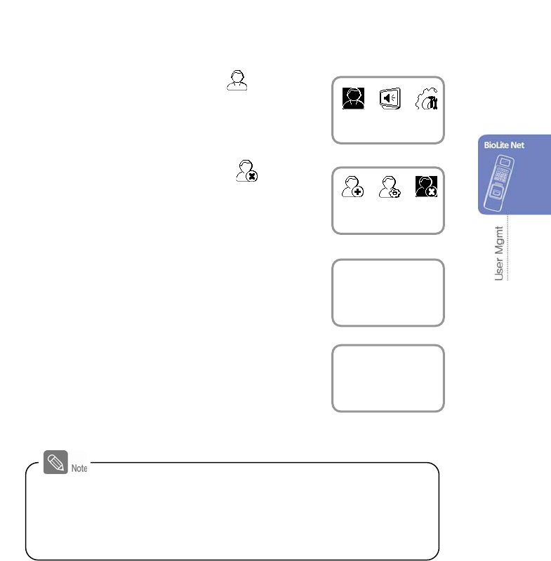
2.3 Deleting a user data
You can delete unnecessary user data.
1. Use / buttons to select the User ( ) icon
and press OK.
2. Use / buttons to select the Delete ( ) icon
and press OK.
3. After entering the ID or finger to delete and press
OK.
4. When the action is successfully made, the
message Deletion appears.
※The deleted user cannot be recovered.
If necessary, enroll it again.
- If all the users including the administrator are deleted, you must
register the initial administrator again (see 1.4.1).
- When an administrator is deleted by mistake except normal users,
the initial administrator registration step does not require registering
normal users.
User
Delete
Enter ID/Fin
g
e
r
4
Delete
Deletion
32
3. Configuration for Screen and
Sound
3.1 Date, Time
You need to set the current system date and time.
After setting the date and time, the log data can store correct information.
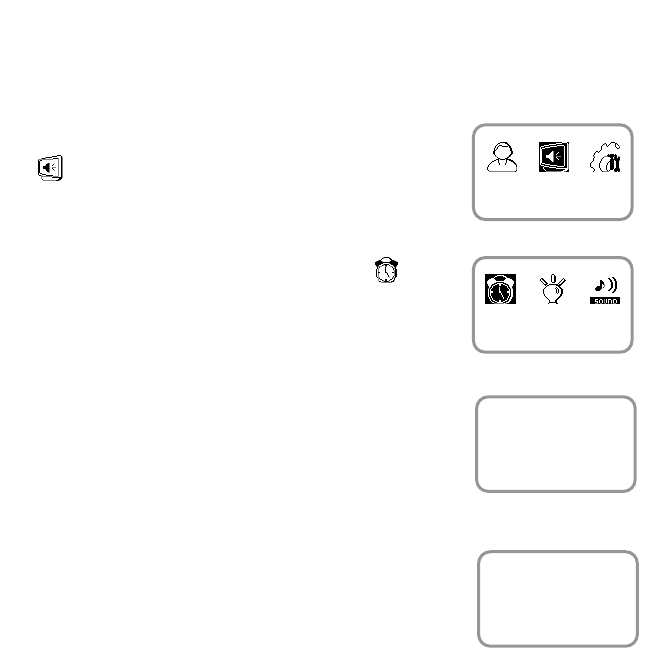
1. Use / buttons to select the Screen, Sound
() icon and press OK.
2. Use / buttons to select the Date, Time ( )
icon and press OK.
3. Enter the current date by following the suggested
format and press OK.
For example, in case of November 15 in 2008,
enter “20081115” and press OK.
4. Enter the current time by following the suggested
format and press OK.
For example, in case of 10:20 55 AM,
enter “102055” and press OK.
Screen, Sound
Date, Time
Date
(
YYYYMM00
)
20081115
Date, Time
Time
(
hhmmss
)
102055
Date, Time
33
3.2 Backlight
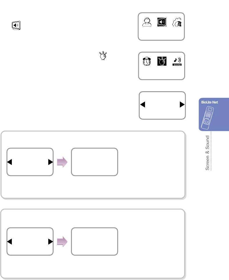
1. Use / buttons to select the Screen, Sound
() icon and press OK.
2. Use / buttons to select Backlight ( ) icon
and press OK.
3. Use / buttons to select a backlight operation
status and press OK.
Always On
On at Use
When no operation is made,
it sets the time (second) to
switch the screen.
Enter the backlight-on time
(second) on the menu window.
Mode
Always On
Backlight
Timeout(sec)
20
Menu Duration
Mode
On at Use
Backlight
Timeout(sec)
20
Backlight
※When no input is made, it sets the time to exit from
the menu.
※When no input is made on the menu window, it sets
the time to automatically turn off the backlight.
Screen, Sound
Backlight
Mode
Always On
Backlight
Use / buttons to
select the Always On and
press OK.
Use / buttons to
select the On at Use and
press OK.

34
3.3 Sound
1. Use / buttons to select the Screen, Sound
() icon and press OK.
2. Use / buttons to select Sound ( ) icon
and press OK.
3. Use / buttons to select the sound operation status and press OK.
Or
Screen, Sound
Sound
Mode
On
Sound
Mode
Off
Sound
35
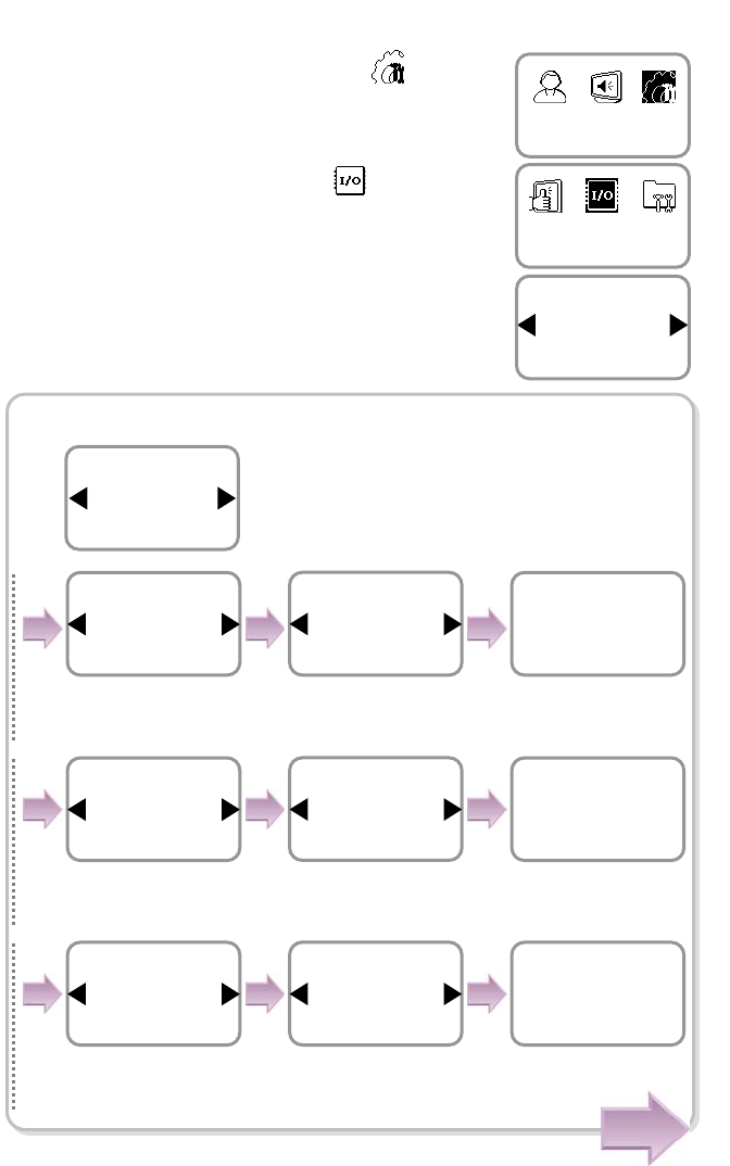
4. Device Configuration
4.1 Authorization
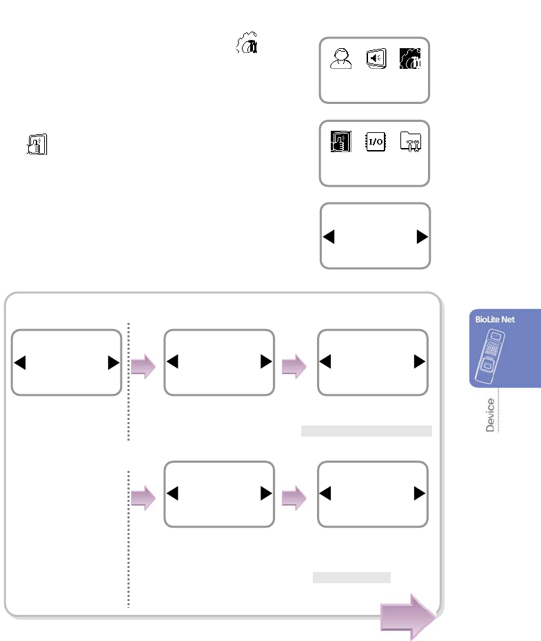
1. Use / buttons to select the Device ( ) icon
and press OK.
2. Use / buttons to select the Authorization
() icon and press OK.
3. Use / buttons to select any of Fingerprint,
and Operation Mode and press OK.
In case of Fingerprint
Authorization
Device
Item
Fingerprint
Authorization
Use / buttons to
select Fingerprint and
press OK.
Use / buttons to
select Security Level
and
press OK.
Use / buttons to select
Security Level and press OK.
* Normal /Secure/More Secure
Use / buttons to
select Image Quality and
press OK.
Use / buttons to
select Image Quality and
press OK.
*Normal/High/Low
Item
Security Level
Fingerprint
Security Level
Normal
Fingerprint
Item
Image Quality
Fingerprint
Image Quality
Normal
Fingerprint
Item
Fingerprint
Authorization
Cont.
36
Cont.
Item
Fast Mode
Fingerprint
Fast Mode
Auto
Fingerprint
Item
Scan Timeout
Fingerprint
Scan Timeout(sec)
10
Fingerprint
Item
Matching Timeout
Fingerprint
Matching Timeout(sec)
3
Fingerprint
Use / buttons to
select Sensitivity and
press OK.
Use / buttons to
select Sensitivity level
and press OK.
Use / buttons to
select Check Duplicate
and press OK.
Item
Sensitivity
Fingerprint
Sensitivity
7
Fingerprint
Item
Check Duplicate
Fingerprint
Check Duplicate
Not Use
Fingerprint
Use / buttons Check
Duplicate and press OK.
* Not Use /Use
Use / buttons to
select Fast Mode and
press OK.
Use / buttons to
select Scan Timeout and
press OK.
Use / buttons to
select Matching
Timeout and press OK.
Enter Scan Timeout
(second) and
press OK.
Enter Matching Timeout
(second)and press OK.
Use / buttons to
select desired Fast Mode
and press OK.
*Auto/Normal/Fast
/Faster
37
※
Security Level
: The higher the security level, the more sensitive the fingerprint
recognition. But the authorization failure rate can increase.
※
Image Quality
: It is the image quality level used when entering the fingerprint data.
In case of Low, the fingerprint can be easily input but the correct
authorization is not guaranteed.
※
Sensitivity
: The higher the value, the more sensitive the sensor.
※
Check Duplicate
: When enrolling a user, it determines whether or not to check the
fingerprint data is already enrolled.
※
Fast Mode
: You can set the fingerprint recognition speed. If it is set to Fast,
the recognition accuracy may decrease.
※
Scan Timeout
: You can set the terminal standby time for entering fingerprint.
If entry is not made within the specified time, the message,
‘Entry time is over” appears.
※
Matching Timeout
: You can set the maximum authorization time after entering fingerprint.
If this time limit expires, matching stops and the authorization fails.
※
Template Type
: Format used in the terminal when identifying fingerprints (SUPREMA/SIF)
- SUPREMA: SUPREMA’s own template format, SIF: ISO/IEC compatible template format
(To change the template format, there must be no fingerprint data stored on the terminal.)
Item
Template Type
Fingerprint
Template Type
SUPREMA
Fingerprint
Use / buttons to
select Template Type
and press OK.
Use / buttons to
select template format
and press OK.
*SUPREMA/SIF
38
Cont.
In case of Operation Mode
※
Sensor Mode: *
Always On
/ID Entered/OK Pressed
- Always On: The sensor always waits for a fingerprint input.
- ID Entered/OK Pressed: If you enter ID or press OK, you can enter the time zone
for using the sensor.
※
Applied time: Use the dedicated PC software for setting the time zone except
All Time and Not Use. With the terminal, you cannot add and edit it but only selection
is not possible.
※Auth Mode: *Finger Only/PIN Only/Finger or PIN
/ Finger and PIN /Card Only
If no authorization setting exists for each user,
the user authorization method that has been set
on the terminal is applied.
※Double Mode: When consequent two users are
authorized successfully, entrance
and exit are allowed.
Use / buttons to ◀▶
select the applicable
time zone and press
OK.
Schedule
All Time
Always On
Item
Operation Mode
Authorization
Use / buttons to
select Sensor Mode
an
p
ress OK.
Use / buttons to
select a sensor mode.
*Always On/ID
Entered/OK Pressed
Item
Sensor Mode
Operation Mode
Sensor Mode
Always On
Operation Mode
Use / buttons to
select Operation
Mode an
p
ress OK.
Use / buttons to◀▶
select the authorization
method press OK.
Use / buttons to ◀▶
select the applicable
time zone and press
OK.
Use / buttons to
set whether or not to
use the double mode
and press OK.
Item
Auth Mode
Operation Mode
Auth Mode
Finger Only
Operation Mode
Schedule
All Time
Finger Only
Double Mode
Not Use
Finger Only
Use / buttons to
select Auth Mode and
p
ress O
K
.
39
※Card entry methods:
- Use Template: After placing the user card, enter your fingerprint and PIN. Then the
terminal matches the enrolled fingerprint template with the template
in the card for identification.
- Use CSN: Identifies only the serial number of the card.
Use / buttons to◀▶
set whether or not to
use the mode and
press OK.
Use / buttons to◀▶ set
whether or not to use
cards and press OK.
Use / buttons to◀▶
select the card entry
method and press OK.
* Use Template/Use CSN
Item
Private Auth Mode
Operation Mode
Private Auth Mode
Use
Operation Mode
Item
Card
Operation
Card
Use
Operation Mode
Type
Use Template
Card
Use / buttons to
select Private Auth
Mode an press OK.
Use / buttons to
select Card an press OK.
40
4.2 In/Out
1. Use / buttons to select the Device ( ) icon
and press OK.
2. Use / buttons to select In/Out () icon and
press OK.
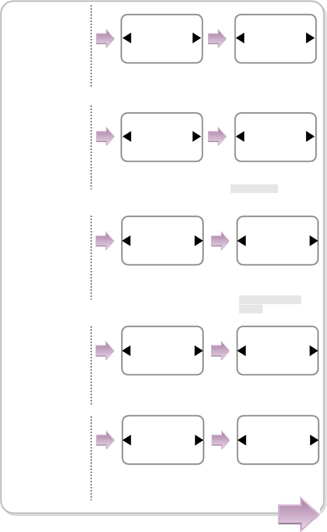
3. Use / buttons to select any of Serial Conn.,
Tamper On, Door Wiegand, and TCP/IP and
press OK.
In case of Serial Conn. (selection of connection method)
Use / buttons to◀▶ set
whether or not to use the
termination and press OK.
The completion
message window
appears.
Type
Host
Serial Conn.
Termination
Not Use
Serial Conn.
Completed
Use / buttons to◀▶ set
whether or not to use the
termination and press OK.
The completion
message window
appears.
Type
Slave
Serial Conn.
Termination
Not Use
Serial Conn.
Completed
Use / buttons to ◀▶ set
whether or not to use the
termination and press OK.
The completion
message window
appears.
Type
Ext. Host
Serial Conn.
Termination
Not Use
Serial Conn.
Completed
※Serial Conn.: It is used
for RS485 communication
or direct PC connection.
Device
In/Out
Item
Serial Conn.
In/Out
Item
Serial Conn
.
In/Out
Use / buttons to
select Serial Conn.
and
press
OK.
Cont.
Use / buttons to
select Host
and press
OK.
Use / buttons to
select Slave
and press
O
K
.
Use / buttons to
select Ext. Host
and press
O
K
.
41
※ Methods
- PC Conn.: Directly connects to PC through RS485
- Host/Slave: Connects between terminals through RS485. Used when the terminal
interoperates with the BioAdmin software.
(Refer to the BioAdmin manual.)
- Ext. Host/Ext. Slave: Connects between terminals through RS485. Used when
the terminal interoperates with the BioStar software.
(Refer to the BioStar manual.)
- Termination: Used when the communication line is too long or the signal strength
changes drastically (It enforces the signal strength).
- Host/Slave, Ext. Host/Ext. Slave: Connects between terminals through RS485.
The communication speed is fixed to
115200 baudrate.
The completion
message window
appea
r
s
.
Completed
Use / buttons to ◀▶ set
whether or not to use the
termination and press OK.
The completion
message window
appears.
Type
Ext. Slave
Serial Conn
.
Termination
Not Use
Serial Conn.
Completed
Use / buttons to◀▶ set
whether or not to use the
termination and press
The completion
message window
appears.
Type
Not Use
Serial Conn.
Termination
Not Use
Serial Conn
Completed
Use / buttons to◀▶
set whether or not to
use the termination
and
p
ress O
K
.
Baudrate
115200
Serial Conn
.
Type
PC Conn
.
Serial Conn
.
Termination
Not Use
Serial Conn.
Use / buttons to
select Ext. Slave
and
p
ress
O
K
.
Use / buttons to
select Not Use
and press
O
K
.
Use / buttons to
select PC Conn.
and
p
ress
O
K
.
Use / buttons to
select Baudrate
and press
OK.
*115200/57600/38400
/19200
42
In case of Tamper On
※
Tamper
: *Ignore/Locked
- Locked: When the device is forcibly removed, the Device is locked.
(To release the lock, the administrator must perform authorization.)
Item
Tamper On
In/Out
Press OK.
Use / buttons to
select Tamper On
and
press
OK.
Use / buttons
to select a tamper
method.
Tamper On
Ignore
In/Out
43
In case of Door (When using the internal relay)
※
Opening Mode
- Temporary Open: When the door is open, it is automatically closed after a specific time.
- Toggle: The door is opened after the first authorization success and it remains unlocked
until the second authorization success.
※ It is used only when the stand-alone BioLite Net is installed without
interoperating with the dedicated PC software.
Item
Door
In/Out
Use / buttons
to select Door
and
press
OK.
Use / buttons
to select Internal
and press
OK.
Use / buttons to select
Exit Button
and press
OK.
* Not Use/ Input 0/ Input 1
Relay
Internal
Door
Exit Button
Input 0
Internal
Use / buttons to
select the type for
Exit
Button
and press
OK.
*N.O/N.C
Type
N.O
Exit Button
Door Sensor
Input 1
Internal
Use / buttons to
select a
door sensor type
and press
OK.
*N.O/N.C
Use / buttons to
select Door Sensor
and
press
OK.
*
Not Use/Input
Opening Mode
Temporary Open
Door
Held Open Alarm
Not Use
Door
Open Time(sec)
3
Door
Type
N.O
Door Sensor
Use / buttons to
select a opening mode
and press
OK.
*Temporary Open/ Toggle
Enter the time and
press OK. Use / buttons to select
the type for Held Open Alarm
and press
OK.
* Not Use /Sound/Backlight/
Sound& Light/SIO Relay0/
SIO Relay1
Enter the held open time by
using the Numeric buttons
and press OK.
*Held Open Time: Alarm
ringing time when the open
door is not closed.
Forced Open Alarm
Not Use
Door
Completed
Use / buttons to select the
type for Forced Open Alarm and
press OK.
*Not Use/Sound/ Backlight/Sound
and Light/SIO Relay0/ SIO Relay1
The completion
message window
appears.
Held Open Time(sec)
30
Door
When you exit from the menu before completing the relay setup, the
configuration is not stored so please finish configuration until the
message “Complete” appears.
44
In case of Door (When using the SIO relay)
※It is used only when the stand-alone BioLite Net is installed without
interoperating with the dedicated PC software.
Use / buttons to
select the relay type
and
press
OK.
Use / buttons to
select the exit button
and
press
OK
.
* Not Use/SIO Input0/
SIO Input1
Relay
SIO Relay0
Door
Exit Button
SIO Input0
SIO Relay0
Item
Door
In/Out
Use / buttons to
select Door
and press
OK.
Use / buttons to select
the type of the exit button
and press
OK.
*N.O/N.C
Type
N.O
Exit Button
Door Sensor
SIO Input1
SIO Relay0
Use / buttons to
select the door sensor
type
and press
OK.
*N.O/N.C
Use / buttons to
select the door sensor
and press
OK.
*Not Use/ SIO Input1
Type
N.O
Door Sensor
Enter the time and press
OK
and press
OK. Use / buttons to
select the alarm type
and
press
OK.
*Not Use/Sound/Backlight/
Sound and Light/SIO
Relay0/SIO Relay1
Held Open Alarm
Sound
Door
Enter the time for Held Open
Alarm by using the Numeric
buttons and press OK.
*Held Open Time: Alarm
ringing time when the open
door is not closed.
Held Open Alarm(sec)
30
Door
Opening Mode
Temporary Open
Door
Use / buttons to
select the type of the
opening mode
and press
OK.
*Temporary Open/ Toggle
Open Time(sec)
3
Door
Use / buttons to select
the type for Forced Open
Alarm and press OK.
*Not Use/Sound/
Backlight/Sound and Light/SIO
Relay0/ SIO Relay1
The completion message
window appears.
Forced Open Alarm
Not Use
Door
Complete
45
In case of Wiegand
Wiegand ※types: *Card ID In/Card ID Out/User ID In/User ID Out
- Card ID In: The card ID is entered.
- Card ID Out: The card ID is output.
- User ID In: The user ID is entered.
- User ID Out: The user ID is output.
Use / buttons to◀▶ select
Wiegand and press OK.
*Card ID In/ Card ID Out/User ID
In/ User ID Out/Not Use
Item
Wiegand
In/Out
Type
Card ID In
Wiegand
When the user whose user ID is 2 registers the card ID (1234567),
- Card ID In: When “1234567” is entered through the Wiegand port, the
user is successfully authorized.
- Card ID Out: When the user card is read through the terminal, the card ID
“1234567” is output through the Wiegand port.
- User ID In: When “2” is entered through the Wiegand port, the user is
successfully authorized.
- User ID Out: When the user is successfully authorized, the user ID “2” is
output through the Weigand port.
※For Wiegand connection, see “6.4.7 Connection Wiegand.”
※Standard 26Bit Format is used for Wiegand In/Out format. The setting
can be changed using the dedicated PC software.
Use / buttons to
select Wiegand
and
press
OK.
46
In case of TCP/IP
.
※IP Address/Gateway/Subnet Mask Setup: If DHCP is used, the values for
IP address, gateway, and subnet mask are automatically assigned. Otherwise, set DHCP
to Not Use and enter the corresponding values.
(When the right arrow is pressed, “.” is entered while the left arrow deletes characters
one by one.)
Server: To directly connect the server of the dedicated PC software that enables
monitoring and setting the terminal, use Server for its setup and enter the values for
IP address and port number. (Refer to the dedicated PC software manual.)
TCP/IP Port, Server Port: Should be the same values defined in the dedicated
PC software. It is recommended to set the TCP/IP port to “1471” and Server to “1480.”
(When the port number is modified as you want, TCP/IP communication may not be active.)
When you exit before
finishing the TCP/IP
setting, the change is
not stored so proceed
with the settings until
the message
“Completed” appears.
Item
TCP/IP
In/Out
Use / ◀▶buttons to set
whether or not to use
DHCP and press OK.
DHCP
Not Use
TCP/IP
IP Address
192.168.1.35
TCP/IP
Gateway
192.168.1.10
TCP/IP
Subnet Mask
255.255.255.0
TCP/IP
※It directly connects to the server for the dedicated
PC software without usin
g
DHCP.
Server
Use
TCP/IP
Server IP
192.168.1.30
TCP/IP
Server Port
1480
TCP/IP
Port
1471
TCP/IP
The completion
message window
appears.
Completed
100Base-T Support
Not Support
TCP/IP
Use / buttons to set
whether or not to
support 100Base-T
and press OK.
Use / buttons to
select the TCP/IP and
press OK.
Enter IP address and
press OK.
Enter Gateway using
numeric and arrow
button and press OK.
Enter IP address using
numeric and arrow
button and press OK.
Enter Port and press
OK.
Use / buttons to
select the Use and
press OK.
Enter Server Port and
press OK.
Enter Server IP address
using numeric and arrow
button and press OK.
47
4.3 System
1. Use / buttons to select the Device ( ) icon
and press OK.
2. Use / buttons to select the System ( )
icon and press OK.
3. Use / buttons to select any of Information,
Factory Default, Delete All Log, Delete User DB,
and Language and press OK.
In case of Information
Device
System
Item
Information
System
Item
Log
Information
Use / buttons to
select Not Use
and
p
ress
O
K
.
Filter
Not Use
Log
The entire logs appear.
(Use / buttons to see
the previous/next logs.)
6/18 16:21(1)
Set Time
6/18 14:20(3)
Delete OK
Use / buttons to
select Log
and press
OK.
Use / buttons to
select Use
and press
OK.
Filter
Use
Log
User
All
Filter
Use / buttons to
select any of All and
Select ID
and press
OK.
Use / buttons to
select any of All and
Specify Date
and press
OK.
The log filtering result
appears on the screen.
(Use / buttons to see
the previous/next logs.)
6/18 14:20(3)
Delete OK
6/18 13:46(3)
Enroll OK
Use / buttons to select
the event type
and press
OK.
*All/Success/Failure/In/Out/
System
Date
All
Filter
Event
All
Filter
※
Filter
-
Not Use
: Displays all.
-
Use
: Only the specified log
is displayed.
(ID/Date/Event Type)
※When the date is specified,
the logs occurred earlier than
the specified date appear.
48
In case of Information — Continued
In case of Factory Default
※In case of Initialize, the settings are deleted but the log data and user DB are not
deleted.
Use / buttons to
select Num. Of User
and press
OK.
The version of the
firmware appears.
Item
Num. Of User
Information
Item
Firmware Ver.
Information
User
Templates
6/10000
4/5000
Firmware Ver.
V1.0_081127
Information
Use / buttons to
select Firmware Ver.
and press
OK.
The version of the
hardware appears.
Item
Hardware Ver.
Information
Hardware Ver.
11563(Rev.C)
Information
Use / buttons to
select Hardware Ver.
and press
OK.
The number of current users
and the number of fingerprints
enrolled appear.
Item
Factory Default
System
Use / buttons to
select Factory Default
and press OK.
Use / buttons to
determine whether or
not to initialize it.
*Cancel/ Initialize
Initialize?
Initialize
Factory Default
In case of Initialize,
the message
Initialized appears.
Initialized
49
In case of Delete All Log
※In this case, all users’ in/out data are deleted and they cannot be recovered.
In case of Delete User DB
※In this case, the users’ DB is completely deleted so you must immediately
register the initial administrator (see 1.4.1).
※When the user DB is deleted, it cannot be recovered.
In case of Language
In case of Delete,
the message
Deletion appears.
Use / buttons to
select Delete All Log and
press OK.
Use / buttons
to determine
whether or not to
delete them.
*Cancel/ Delete
Item
Delete All Log
System
Delete?
Delete
Delete All Log
Deletion
Item
Delete User DB
System
In case of Delete,
the message
Deletion appears.
Use / buttons to
select Delete User DB
and press OK.
Use / buttons
to determine
whether or not to
delete the user DB.
*Cancel/Delete
Delete?
Delete
Delete User DB
Deletion
Use / buttons to
select Language and
press OK.
Use / buttons
to select the
language.
* English/ Korean
Press OK.
Item
Language
System
Item
English
Language
50
In case of Wallpaper
※Types
- Type1: Only the time appears on the wallpaper screen.
- Type2: The number of users and TCP/IP connection status appears
on the wallpaper screen.
In case of (8/5000) U - Eight people are registered among 5000
(number of people that can be registered) and it is unlinked.
Characters on the Type2 wallpaper
- U: Unlinked (LAN is not connected.)
- D: Disconnected (LAN is connected but TCP/IP communication is not active.)
- C: Connected (LAN is connected and TCP/IP communication is active.)
Use / buttons to ◀▶
select Wallpaper and
press OK.
Use / buttons to ◀▶
select the type and
press OK.
*Type1/Type2
Item
Wallpaper
System
Wallpaper
Type1
System
BioLite Net
10:33:02
Type1
BioLite Net
10:33:02
(8/5000) U
Type2
51
5. Attendance Management
5.1 Operating environment
When an event (attendance, leaving, return, and outside duty) is received from the
terminal, it is reported to the server of the dedicated PC software. You can create a
report from the events stored in the server.
With the dedicated PC software, you can also define new event other than the above-
mentioned basic events and apply it to the report.
In case of basic events provided, each event causes the door to open. You can
configure the settings according to the environment through the dedicated PC software.
Event

52
5.2 Setup for attendance management
1. Use / buttons to select the Device ( ) icon
and press OK.
2. Use / buttons to select the Authorization
() icon and press OK.
3. Use / buttons to select the Operation Mode
and press OK.
4. Use / buttons to select the Time
Attendance and press OK.
5. Use / buttons to select the Operation Mode
of Time Attendance and press OK.
Operation modes※: *Key Input/Fixed/Manual/Auto/Not Use
- Key Input: In usual time, the function is inactive. When ◀/▶ buttons are pressed,
you can select the attendance status. When a user authorization is successful,
the selected attendance log is recorded.
- Fixed: A specific attendance status continues. When a user authorization is successful,
the corresponding log is recorded.
- Manual: The active attendance status appears on the screen and it can be changed
using ◀/▶ buttons. Once it is changed, the status continues until another
selection is made. Every authorization success makes the log recorded.
- Auto: The active attendance status appears on the screen. Fore each time zone,
the active attendance statuses are fixed.
- Not Use: The function is not available.
Item
Time Attendance
Operation Mode
Time Attendance
Key Input
Operation Mode
Authorization
Device
Item
Operation Mode
Authorization
53
5.3 Operation modes
5.3.1 Key Input
When the operation mode is set to “Key Input,” this mode is used.
5.3.2 Manual
When the operation mode is set to “Manual”, this mode is used.
In case of Manual
The door opens
with a confirmation
message.
ID: 8
In
Select the desired
event and perform
user authorization.
BioLite Net
10:33:02
Move to the desired
event by using /
buttons.
Select
In
Type
The desired event
appears.
BioLite Net
10:33:02
Move to the desired
event by using /
buttons.
In
08:30:43
12/01/2008
54
In case of Manual
※Manual:
It is convenient to those who need to change an event type manually everytime they
enter or leave.are in and out...
5.3.2 Auto
When the operation mode is set to “Auto,” this mode is used.
This mode can set the corresponding time zone for each attendance event through the
dedicated PC software. Then the fixed event is set for the corresponding time zone.
In case of Auto
Auto※: While the event type and time zone are set through the dedicated
PC software, you can totally use this mode for all the users who are
entering or leaving.
The Users identify the card
or fingerprint according to
the authorization method.
In
08:30:43
12/01/2008
The door opens
with a confirmation
message.
ID: 8
In
The users identify the card
or fingerprint according to
the authorization method.
Out
18:35:55
12/01/2008
The door opens
with a confirmation
message.
ID: 8
Out
The event for the
corresponding time
zone appears.
55
5.3.3 Fixed
When the operation mode is set to “Fixed,” this mode is used.
This mode is used after fixing the event through the dedicated PC software if required.
In this case, the setting can be changed only through the dedicated PC software and
you cannot change the attendance event through the terminal.
※ Fixed: This mode is available only when the desired event is set for all the users
who are entering or leaving.
The users identify the card
or fingerprint according to
the authorization method.
Out
18:35:55
12/01/2008
The door opens
with a confirmation
message.
ID: 8
Out
The preset event
appears.

56
6. FAQ
6.1 Error messages
Error Message Description
!Not Administrator A normal user tries to enter the menu.
!Not Authorized The fingerprint authentication for the administrator fails when entering
the menu.
!Device Locked The device is locked because the case has been open.
!Failed The number of users exceeds 5000, so you cannot enroll more users.
!No Log There is no log data.
!Unknown Finger The entered fingerprint for entering the menu or editing/deleting a user
data does not exist.
!Cannot Change
A template already exists when you want to change the template format.
!Failed The user ID to delete does not exist.
!ID In Use The user ID to enroll already exists.
!Unknown ID The user ID that does not exist in the device is entered.
!Wrong PIN The entered password for authentication is not matched the enrolled
one.
!Invalid Value An invalid value is entered.
!Mode Error The authorization mode is different from the setting.
!Not Matched
The entered fingerprint or password is not matched to the enrolled one.
- In case of fingerprint entry, the entered two fingerprints of the same
finger are different.
!Time Out The fingerprint data is not entered while the sensor is active.
!Not Recognizable The fingerprint data cannot be extracted due to wrong finger input.
!Duplicated Time The time zone is duplicated.
!Duplicate Finger When enrolling a user fingerprint, the fingerprint that has been input
already exists in the device (when checking the duplicated case).
!Access Restricted The authentication trial happens except for the allowed time zone.
!No Card You tried authorization with a unregistered card.

57
6.2 Troubleshooting
Category Trouble Solution
Power
The power is
supplied but the
device does not
operate.
- When the device is disconnected from the bracket, it
may not work when using the tamper switch.
- Check the adapter or power cable.
Password
The password is lost. - Enter the queried password after contacting the
administrator in case of a normal user.
- When the administrator password is lost, contact with the
installation a
g
enc
y
.
The locked door is
not open after
entering the
password and
p
ressin
g
O
K
.
- Check whe
t
her the correct password is input.
- Check whether you have changed the password
recently.
- If you cannot find the password, contact the
administrator.
Fingerprint
The fingerprint has
been enrolled but its
recognition
encounters an error.
- BioLite Net has the technology of Suprema that won the
first award in FVC2004 and FVC2006 because it has
world number one quality in recognition.
- For better performance in fingerprint recognition, correct
registration is a must.
- Enroll the fingerprint again after seeing
“1.4 Methods for fingerprint input”
- The recognition rate may vary due to the characteristic of
each fin
g
er so enroll the fin
g
erprint of another fin
g
er.
It was good at
recognizing
fingerprints but
suddenly it fails in
recognition.
- Check whether the finger or the sensor is covered with
sweat, moisture, or dust.
- In case the fingerprint has any damage, the device may
consider it as the one of wrong person.
- Wipe the finger or sensor with a dry cloth and retry.
- When the fingerprint is so dry, blow your steam of breath
into it and retr
y
.
Door lock
Even if you close the
door, the door is not
locked.
- The electric lock failure is most likely to happen. Check it
after contacting the installation agency.
Time
The time is not
correct. - BioLite Net has an embedded battery but it can be
discharged by a long time use. Accordingly the time may
not be correct. Correct the time after seeing “3.1 Date,
Time.”
TCP/IP
The terminal data is
not found by the
dedicated PC
software.
- Check the connection status after setting on the terminal
like
Terminal > System > Wallpaper > Type2
.
- When U is displayed: Check the LAN connection status.
- When D is displayed: Check the IP address. If you set
like
Terminal > In/Out -> TCP/IP -> DHCP Not Use
, the
current IP address appears. If you use DHCP, the actual
address received from the DHCP server appears. If the
IP address is set correctl
y
, check the
p
ort number.
Administrator
connection
The administrator
mode cannot be
entered because of
losing the
administrator
password or
resi
g
nation.
- BioLite Net allows the administrator to give access rights
so only the administrator can enter the menu.
- When you have no choice but to enter the administrator
menu, you can be granted an administrator password
after following the predefined procedure.
(Contact with the installation agency.)
58
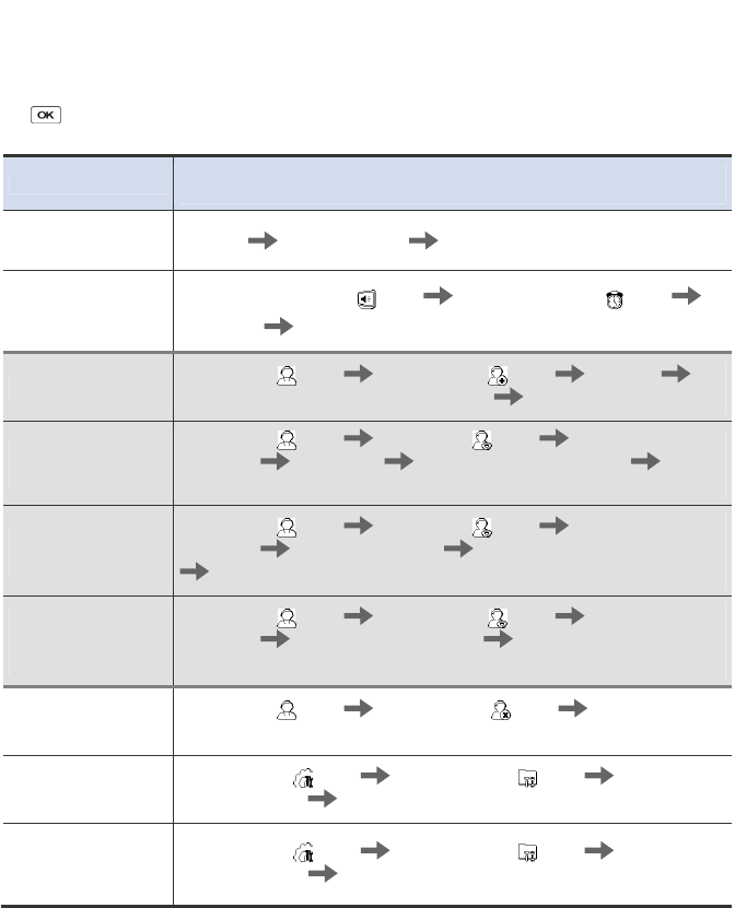
6.3 Usage summary
※ It provides the mainly used functions.
※ button: Used to select the desired function.
Function Method for setting
(Sequentially perform the following items.)
Initial administrator
registration Enter ID Enter password Enter password again
Date & time setting Select Screen, Sound ( ) icon Select Date, Time ( ) icon
Enter date Enter time
User registration Select User ( ) icon Select Enroll () icon Enter ID
Select General or Administrator in Level Enter fingerprint or PIN
User password
modification
Select User () icon Select Edit () icon Enter ID or
fingerprint Select PIN Enter the desired password Enter it
again
User fingerprint
modification
Select User () icon Select Edit ( ) icon Enter ID or
fingerprint Select Fingerprint Enter the fingerprint of the user
Enter it again
User authorization
method
modification
Select User () icon Select Enroll ( ) icon Enter ID or
fingerprint Select Operation Mode Select an authorization
method
User deletion Select User () icon Select Delete ( ) icon Enter ID or
fingerprint to delete
All user deletion Select Device () icon Select System () icon Select
Delete User DB Select Delete
Initialization
(Environment
settings deletion)
Select Device ( ) icon Select System ( ) icon Select
Factory Default Select Initialize
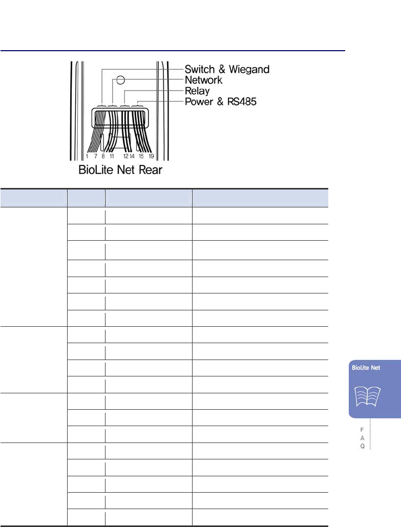
59
6.4 System Installation
6.4.1 Cable specifications
Type No. Name Color
Switch
&
Wiegand
1 SWIN0 Purple
2 GND Gray
3 SWIN1 Brown
4 GND Gray
5 W-DATA0 Orange
6 W-DATA1 White
7 W-GND Black
Network
8 ERX - Yellow
9 ERX + Blue
10 ETX - Orange
11 ETX + Pink
Relay
12 Relay Normal Close Orange (White String)
13 Relay Common Green (White String)
14 Relay Normal Open Gray (White String)
Power
&
RS485
15 Power 12V Red
16 Power Ground Black
17 RS485 Ground White (Black String)
18 RS485 + Blue (Black String)
19 RS485 - Yellow (Black String)
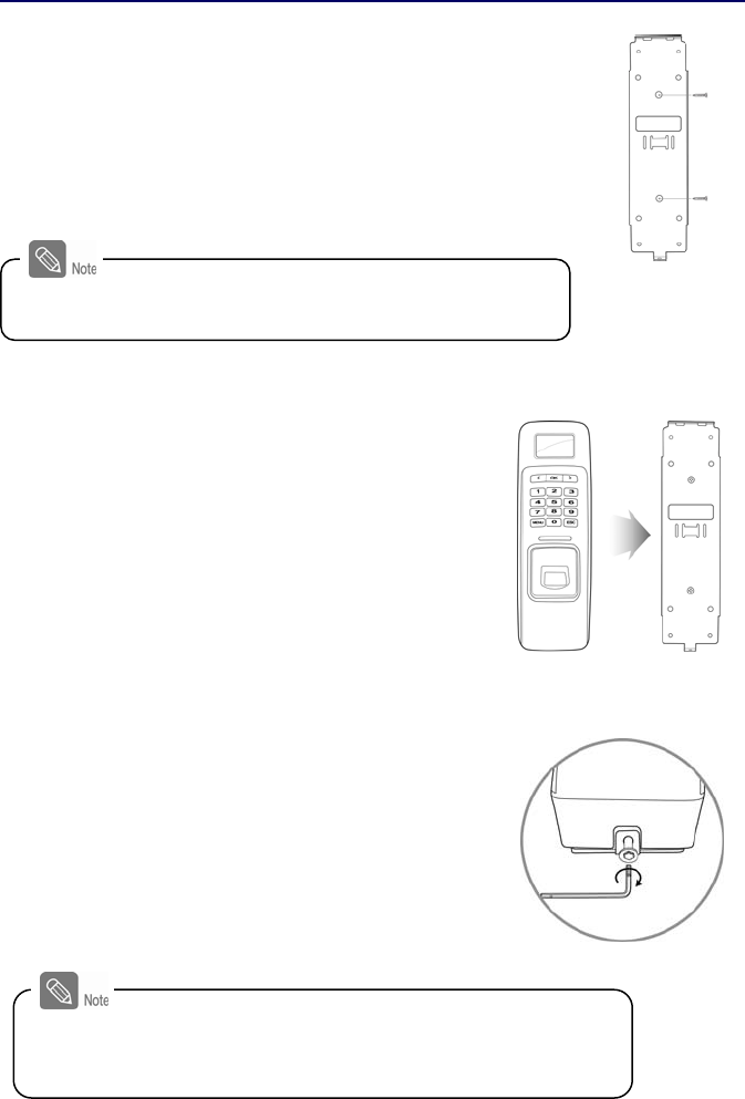
60
6.4.2 Installing the bracket
1. Fix the bracket to the place where BioLite Net is to
be installed using the fixing screws.
2. Install BioLite Net on the bracket.
3. Fix BioLite Net and the wall mount bracket by
rotating the star-shape screw by the hexagonal
wrench.
If the installation place is on concrete, drill holes, insert knife
blocks into the holes, and fix them by using fixing screws.
The extension bracket (Option) is provided for wiring aid
according to the installation environment. Remove the basic
bracket on the body for use of this bracket
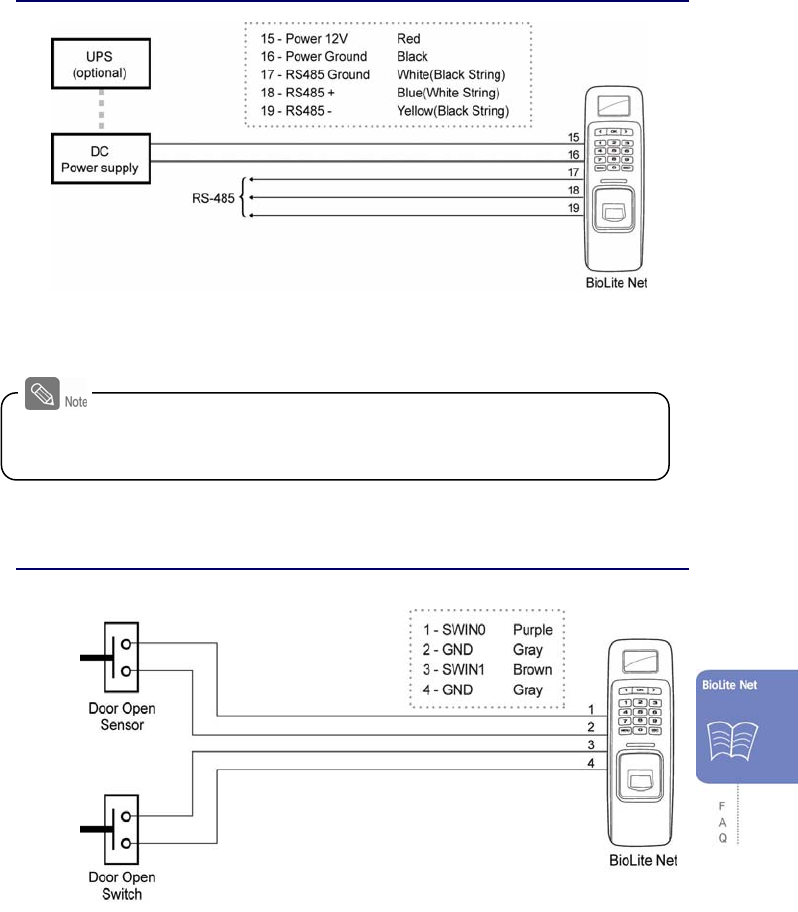
61
6.4.3 Connecting Power & RS-485
※RS-485 is used for connecting to another device
(e.g. PC, BioStation, BioEntry Plus, BioLite Net, Secure I/O, etc.).
6.4.4 Connecting the switch
For power supply, use a product of DC 12V (± 10%) and minimum 500mA.
To share the power adapter with another device, the required current sum of terminal (500mA)
and another device must not exceed the current capacity.
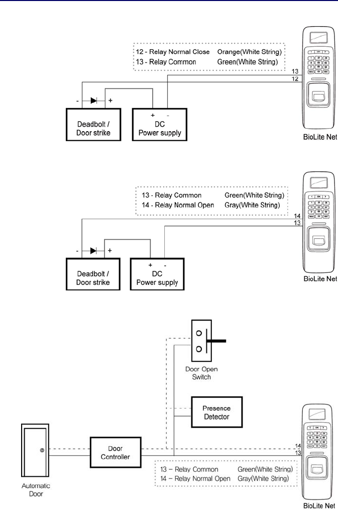
62
6.4.5 Connecting the relay
1. Fail safe lock
2. Fail secure lock
3. Automatic door
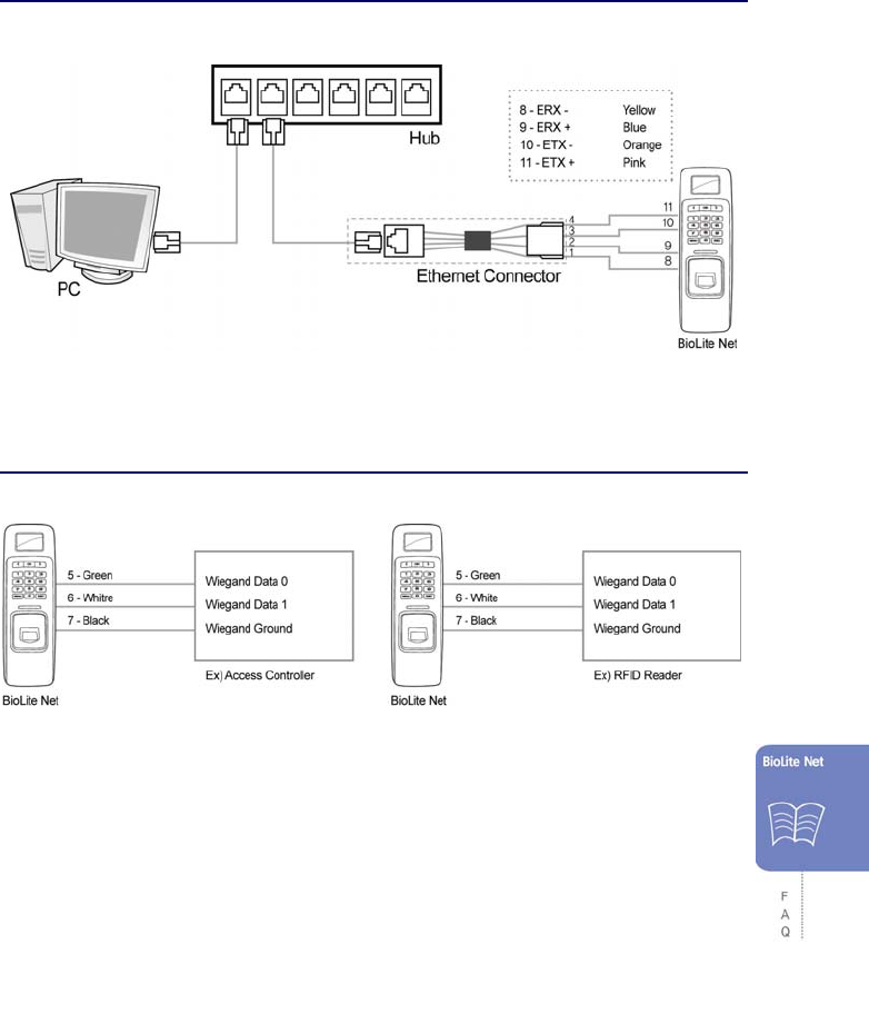
63
6.4.6 Connecting Network
6.4.7 Connecting Wiegand
When BioLite Net is used for
Wiegand output device When BioLite Net is used for
Wiegand input device

64
6.4.8 Electrical specifications
Type Name Min. Typ. Max. Notes
Power Voltage (V) 10.8 12 13.2 Use regulated DC power
adaptor only
Current (mA) - 250
Switch
Input
VIH (V) - TBD -
VIL (V) - TBD
Pull-up
resistance ( )
- 4.7k - The input ports are
pulled up with 4.7k
resistors
Relay Switching
capacity (A)
- - 1
0.3
30V DC
125V AC
Switching
power
(resistive)
- - 30W
37.5VA
DC
AC
Switching
voltage (V)
- - 110
125
DC
AC

65
6.5 Specifications
Item Specification
CPU 400MHz DSP
Fingerprint sensor 500dpi optical sensor
User capacity 5000 users (2 fingerprints per user)
Matching speed Less than 1 second
Operation mode Fingerprint, Password, Fingerprint + Password, Card
IP rate IP65 Class
Internal relay Deadbolt, EM lock, door strike, automatic door
TTL I/O 2 inputs for exit switch and door sensor
Wiegand In/Out 1 Port (Wiegand Input or Wiegand Output is used according to the
configuration.)
LCD 128 x 64 Graphic LCD (Monochrome)
Keypad 3x4 keypad, 3 navigation keys
Log capacity 50,000 events
Rated Voltage
DC 12V (Min. 500mA and above)
(When sharing the power with a device such as electric door lock,
enough power is required considering the power requirement for the
connected device.)
Supportable Cards BioLite Net Model(BLN-OC)
- 13.56MHz Mifare Classic 1K, 4K Card (Read/Write)
- 13.56MHz ISO 14443A compatible Card (CSN Read)
BioLite Net EMProx Model(BLR-OC)
- 125KHz EM4100 compatible Card (Read)
Size 60 x 185 x 40 mm (Width x Height x Depth)
Certified KCC, CE, FCC
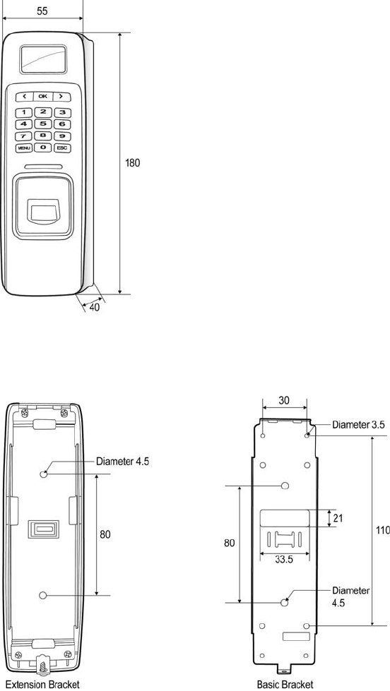
66
Mechanical Specifications

67
6.6 FCC Notice
Caution
Changes or modifications not expressly approved by the manufacturer
responsible for compliance could void the user's authority to operate the
equipment
Warning
This device complies with part 15 of the FCC Rules. Operation is subject to
the following two conditions : (1) This device may not cause harmful
interference, and (2) this device must accept any interference received,
including interference that may cause undesired operation.
Information to User
This equipment has been tested and found to comply with the limits for a
Class B digital device, pursuant to part 15 of the FCC Rules. These limits are
designed to provide reasonable protection against harmful interference in a
residential installation. This equipment generates, uses and can radiate radio
frequency energy and, if not installed and used in accordance with the
instructions, may cause harmful interference to radio communications.
However, there is no guarantee that interference will not occur in a particular
installation. If this equipment does cause harmful interference to radio or
television reception, which can be determined by turning the equipment off
and on, the user is encouraged to try to correct the interference by one or
more of the following measures: ·
1. Reorient or relocate the receiving antenna.
2. Increase the separation between the equipment and receiver.
3. Connect the equipment into an outlet on a circuit different from that to
which the receiver is connected.
4. Consult the dealer or an experienced radio/TV technician for help.