User Manual
English
Version 1.0
FaceStation 2
USER GUIDE
www.supremainc.com
EN 102.00.FS2 V1.00A

Safety Instructions
2
Contents
Safety Instructions .......................................................................................... 4
Introduction ...................................................................................................... 6
Components ................................................................................................................................................... 6
Name and function of each part ............................................................................................................... 7
Cables and connectors ........................................................................................................................... 9
Correct face registration and authentication method........................................................................... 10
Cautions for registering a face ........................................................................................................... 10
Cautions for authenticating a face .................................................................................................... 10
Admin Menu ................................................................................................... 11
All Menus ..................................................................................................................................................... 11
User ................................................................................................................. 12
Registering user information..................................................................................................................... 12
Modifying user information....................................................................................................................... 14
Delete All Users .......................................................................................................................................... 14
View User Usage ......................................................................................................................................... 14
Authentication ............................................................................................... 15
Auth Mode ................................................................................................................................................... 15
Modifying Auth Mode .......................................................................................................................... 15
Delete Auth Mode ................................................................................................................................ 16
Add Auth Mode..................................................................................................................................... 16
Operation ..................................................................................................................................................... 16
Face Recognition ......................................................................................................................................... 17
T&A Mode .................................................................................................................................................... 17
Network .......................................................................................................... 18
Network Settings ......................................................................................................................................... 18
Ethernet .................................................................................................................................................. 18
Wireless ................................................................................................................................................... 19
Server ...................................................................................................................................................... 19
Serial Settings ............................................................................................................................................. 20
RS-485 ..................................................................................................................................................... 20
Display & Sound ........................................................................................... 21
Device ............................................................................................................. 22
Interphone .................................................................................................................................................... 22
Relay ............................................................................................................................................................. 22
Date & Time ................................................................................................................................................ 22
Device Info ................................................................................................................................................... 23
Memory Info ................................................................................................................................................ 23
USB Memory ................................................................................................................................................ 23
Restart Device ............................................................................................................................................. 23
Restore Default ............................................................................................................................................ 23
Factory Default ............................................................................................................................................ 24
Delete the Root Certificate ....................................................................................................................... 24

Safety Instructions
3
Event Log ....................................................................................................... 25
Search Log ................................................................................................................................................... 25
Detail View Log ........................................................................................................................................... 25
Delete All Logs ............................................................................................................................................ 25
View Log Usage .......................................................................................................................................... 26
Troubleshooting ............................................................................................ 27
Checklist before reporting a failure ........................................................................................................ 27
Product specifications .................................................................................. 28
Dimensions ................................................................................................................................................... 29
FCC compliance information ...................................................................... 30
EU Declaration of Conformity (CE) ........................................................... 30
Appendices ..................................................................................................... 31
Escape clause ............................................................................................................................................... 31
Copyright notice .......................................................................................................................................... 31

Safety Instructions
4
Safety Instructions
Observe the following instructions to use the product safely and prevent any risk of injury or property damage.
Warning
Noncompliance with instructions can lead to serious injury or death.
Installation
Do not install the product in a location with direct sunlight, moisture, dust, or soot.
• Fire or electric shock may occur.
Do not install the product in a location with heat from an electric heater.
• Fire or electric shock may occur due to overheating.
Install the product in a dry location.
• Otherwise, product damage or electric shock may occur due to moisture.
Install the product in a location with no electromagnetic interference.
• Otherwise, product damage or electric shock may occur.
The user should not install or repair the product independently.
• Fire, electric shock, or personal injury may occur.
• If the product has been damaged due to independent installation or repair of the product by the user, free A/S service will not be
provided.
Operation
Do not allow liquids such as water, beverages, or chemicals get into the product.
• Fire, electric shock, or product damage may occur.
Caution
Noncompliance of instructions could lead to minor injury or product damage.
Installation
Do not install the power supply cable in a location where people pass by.
• Product damage or physical injury may occur.
Do not install the product near a highly magnetic object such as a magnet, TV, monitor (especially CRT), or speaker.
• Product failure may occur.
Use only a D.C 12 V and 2.5 A or higher power supply adaptor.
• If the proper power supply is not used, the product may not operate properly.
Use a separate power supply for the Secure I/O 2, electric lock, and FaceStation 2, respectively.
• If connecting and using the power supply to these devices together, the devices may malfunction.
When installing a number of devices, allow a space of at least 10cm between the devices for installation.
• Otherwise, one device may affect the RF performance of other devices, resulting in a malfunction.

Safety Instructions
5
Operation
Do not drop the product or apply an impact to the product.
• Product failure may occur.
Manage the password with care; do not to disclose it to others and change it periodically.
• Otherwise, illegal intrusion may occur.
Do not press the buttons on the product forcibly or using a sharp tool.
• Product failure may occur.
When cleaning the product, wipe the product with a soft and dry cloth. Do not apply water, benzene, or alcohol.
• These may cause product failure.
FaceStation 2 uses a capacitive screen and buttons. If the environment is moist from wet weather, or the product surface is
smeared with a large amount of water, wipe the product off with a dry towel before using it.
RTC battery
Replacing the battery with an incorrect type of battery may cause explosion.
Discard the battery according to appropriate regional or international waste regulations.
Introduction
6
Introduction
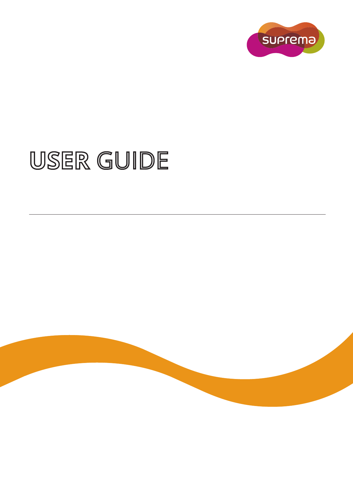
Components
• Components may vary according to the installation environment.
• For additional content regarding product installation, visit the Suprema website (www.suprema.co.kr) and view the installation guide.
Note
FaceStation 2
Wall-mount bracket
Fixing screw
(4 EA)
PVC anchor
(4 EA)
Diode
(1 EA)
Connection cable
(2 pins 1 EA, 3 pins 1 EA, 4 pins 4 EA)
Ferrite core
(1 EA)
Drilling template
Quick guide
120Ω resistor
(1 EA)
Introduction
7
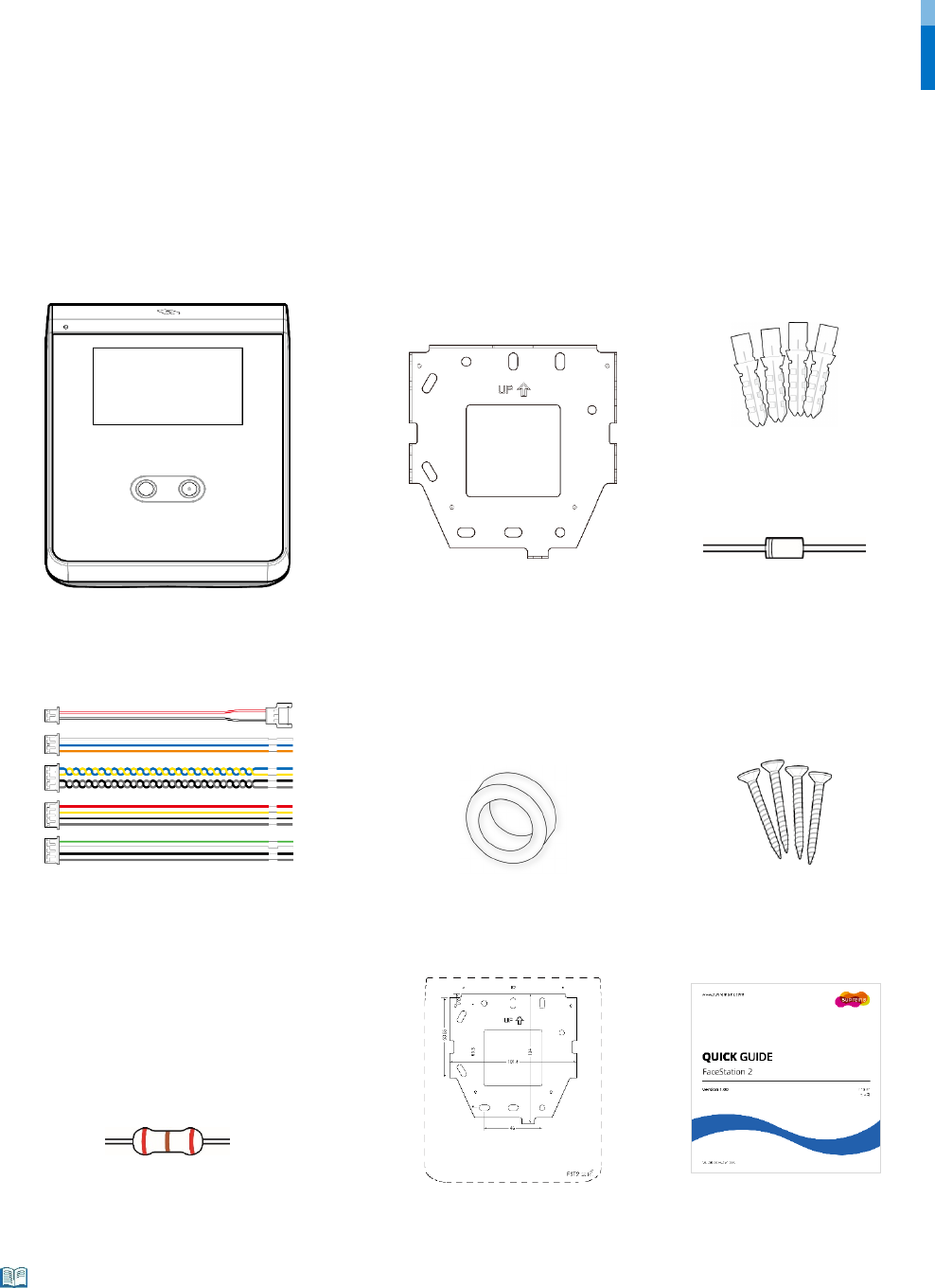
Name and function of each part
Name Description
Microphone Delivers the voice of the user when the interphone is connected.
LCD screen Provides UI for operation.
IR camera Captures IR images.
Camera Captures actual images.
RF card authentication
unit
Scans the card for entrance.
Speaker Delivers sound.
USB memory slot Connects USB memory.
Mini USB cable slot Will be supported in the future.
TTL input (4 pins) Connects the TTL input cable.
RS-485 (4 pins) Connects the RS-485 cable.
Relay (3 pins) Connects the relay cable.
Microphone
LCD screen
TTL input (4 pins)
Power supply (2 pins)
Relay (3 pins)
RF card authentication unit
Speaker
Camera
Ethernet
Wiegand input (4 pins)
Wiegand output (4 pins)
RS-485 (4 pins)
IR camera
USB memory slot
Mini USB cable slot

Introduction
8
Power supply (2 pins) Connects the power supply cable.
Ethernet Connects the Ethernet cable.
Wiegand input (4 pins) Connects the Wiegand input cable.
Wiegand output (4 pins) Connects the Wiegand output cable.
Introduction
9
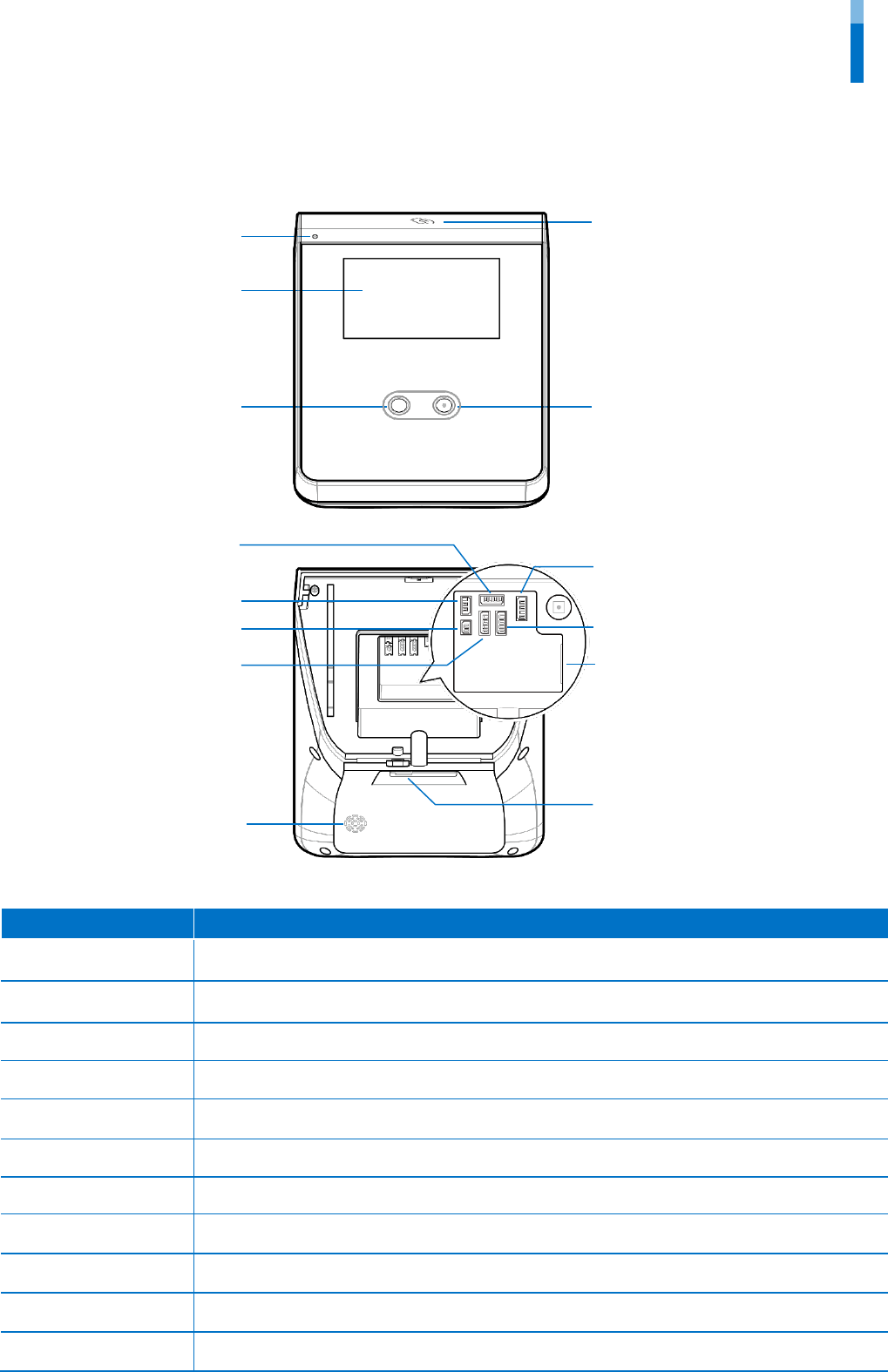
Cables and connectors
Power
Pin Name Color
1
PWR +VDC
Red (white stripe)
2
PWR GND
Black (white stripe)
Relay
Pin Name Color
1
RLY NO
White
2
RLY COM
Blue
3
RLY NC
Orange
RS-485
Pin Name Color
1
485 TRXP
Blue
2
485 TRXN
Yellow
3
485 GND
Black
4
SH GND
Gray
TTL input
Pin Name Color
1
TTL IN0
Red
2
TTL IN1
Yellow
3
TTL GND
Black
4
SH GND
Gray
Wiegand input and output
Pin Name Color
1
WG D0
Green
2
WG D1
White
3
WG GND
Black
4 SH GND Gray

Introduction
10
Correct face registration and authentication method
Cautions for registering a face
• When registering a face, maintain a distance of 40cm to 80cm between the device and the face.
• Be careful not to change the facial expression. (smiling face, drawn face, wink, etc.)
• If you do not follow the instructions on the screen, the face registration may take longer or may fail.
• Be careful not to cover the eyes or eyebrows.
• Do not wear hats, masks, sunglasses or eyeglasses.
• Be careful not to display two faces on the screen. Register one person at a time.
• It is recommended for a user wearing glasses to register both faces with and without glasses.
Cautions for authenticating a face
• Ensure that the face appears inside the guideline displayed on the screen of the device.
• If glasses have been changed, authentication may fail. If the face without glasses has been registered, authenticate the face without
glasses. If only the face with glasses has been registered, authenticate the face with the previously worn glasses again.
• If a part of the face is covered with a hat, a mask, an eye patch, or sunglasses authentication may fail. Do not cover the face; allow the
device to recognize both the eyebrows and the face.
Admin Menu
11
Admin Menu
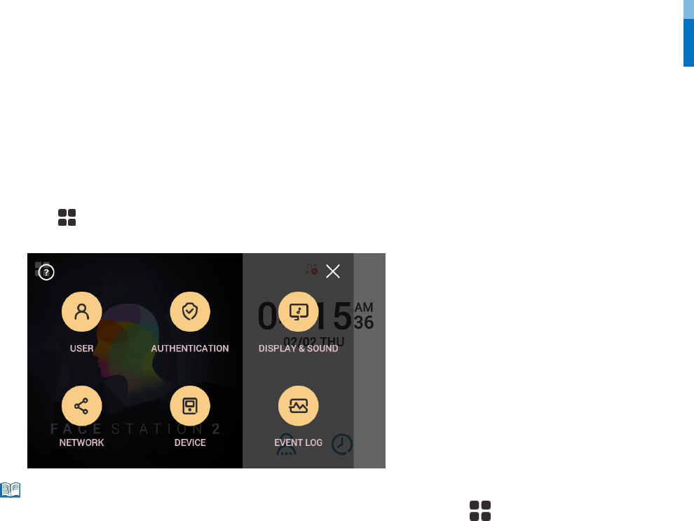
All Menus
1 Press and authenticate with the Admin level credential.
2 Select the desired menu.
• If the administrator has not been designated, the menu screen will be displayed when you press .
Note
User
12
User
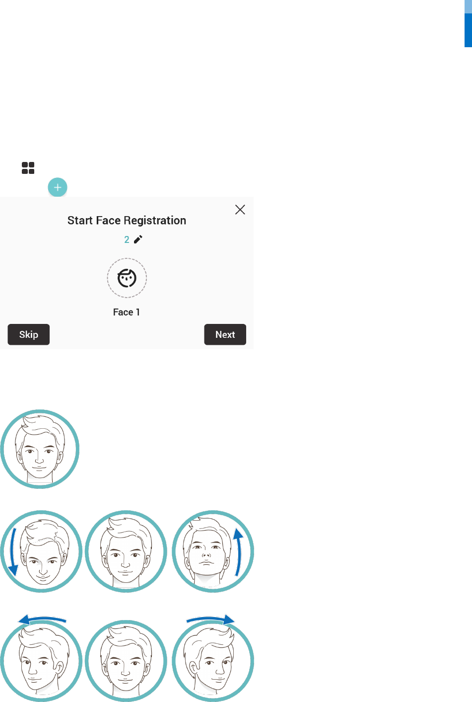
Registering user information
The user information, including the face, can be registered.
1 Press and authenticate with the Admin level credential.
2 Press User > . The face registration wizard will begin.
3 To proceed with the face registration wizard, press Next. To skip, press Skip and go to step 5.
4 If you have pressed Next, register the face according to the instructions on the screen. Face registration is carried out in 3 steps.
(1) Registering the front face
(2) Moving the face up and down
(3) Moving the face to the left and right
When the face registration wizard is used, only the user's face is registered. Modify other information by pressing Edit after registering
the face.
User
13
• When registering a face, maintain a distance of 40cm to 80cm between the device and the face.
• Be careful not to change the facial expression. (smiling face, drawn face, wink, etc.)
• If you do not follow the instructions on the screen, the face registration may take longer or may fail.
• Be careful not to cover the eyes or eyebrows.
• Do not wear hats, masks, sunglasses or eyeglasses.
• Be careful not to display two faces on the screen. Register one person at a time.
• It is recommended for a user wearing glasses to register both faces with and without glasses.
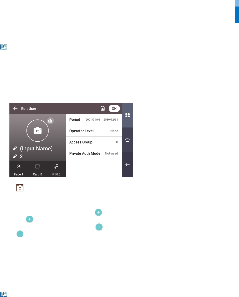
5 If you have pressed Skip, select and set the desired item.
• : Take a picture of a user with the built-in camera.
• Name: Enter the user name.
• ID: Enter the user ID you wish to register. Numbers between 1 and 4294967295 can be entered for ID. If you have changed User ID Type to
Alphanumeric, you can use a combination of alphabetic characters and numbers as ID.
• Face: Register a face for user authentication. Press and register a face according to the instructions on the screen. To register another face,
press again.
• Card: Register a card for user authentication. Press and scan the card that will be assigned to the user. To register an additional card, press
again.
• PIN: Enter the PIN you wish to use. Enter the PIN you wish to use, and then reenter the same PIN for confirmation. Enter a number between 4 and
16 digits to prevent leaking.
• Validity period: Set a Start Date and End Date to use the user account. When you press the first date, you can set Start Date, and when you press
the second date, you can set End Date.
• Operator Level: Select the level you wish to assign to a user.
• Face Group: Select a face group for the user. Face groups can be used only when Group Matching is enabled, and these groups can be registered
only in BioStar 2.
• Access Group: Select an access group for the user. Access groups can only be registered in BioStar 2.
• Private Auth Mode: Change the authentication method according to the user.
Available menus vary according to the set operator level.
• None: This is the general user level; menus cannot be accessed.
• Full Administrator: All menus can be accessed.
• Configuration: AUTHENTICATION, DISPLAY & SOUND, DEVICE and NETWORK menus can be accessed.
• User Management: USER menu can be accessed.
6 When you press OK, settings will be saved.
Note
Note
User
14
Modifying user information
User Management or Administrator can modify the registered user information. A user’s face or card can be added, and the PIN and level
can be modified.
1 Press and authenticate with the Admin level credential.
2 Press User > .
3 Select your search terms. You can search for a user by User ID, Name, Face and Card.
4 Select a user you wish to modify and modify the information by referring to Registering user information.
• To select a user, press and then press OK.
• Access Group can be registered in BioStar 2. For detailed contents regarding registering an access group, refer to the BioStar 2 Administrator
Manual.
Delete All Users
You can delete all registered users at once.
1 Press and authenticate with the Admin level credential.
2 Press User > and select Delete All or select a user you wish to delete.
3 When you press OK, all registered users will be deleted.
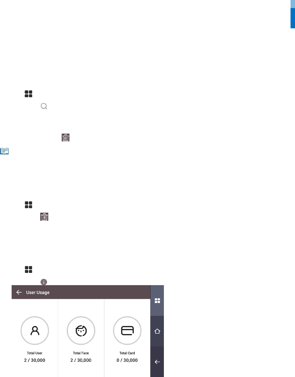
View User Usage
You can see the number of registered users, faces, and cards at a glance.
1 Press and authenticate with the Admin level credential.
2 Press User > .
Note
Authentication
15
Authentication
Auth Mode
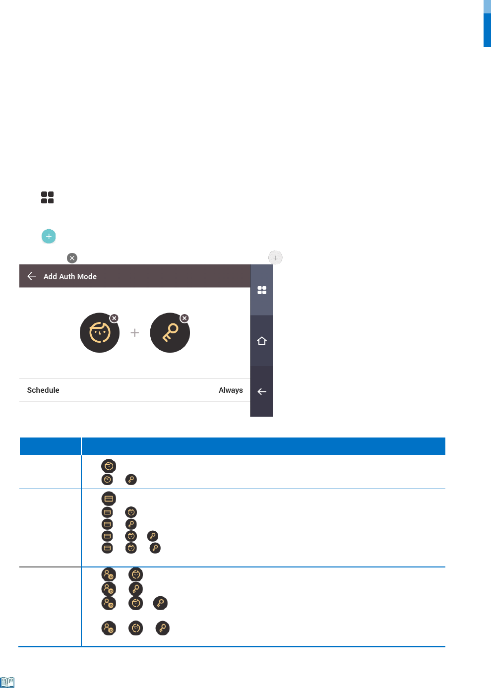
Modifying Auth Mode
You can set the authentication method and schedule according to each credential.
1 Press and authenticate with the Admin level credential.
2 Press AUTHENTICATION > Auth Mode.
3 Press to add an auth mode or press an auth mode you wish to modify.
4 Pressing the icon will delete the selected credential, and pressing will display an addable credential on the screen.
5 Set the desired auth mode and select a schedule.
Classification Description
Face • : Mode allowing authentication with a face only.
• + : Mode to authenticate with a face and PIN.
Card
• : Mode allowing authentication with a card only
• + : Mode allowing authentication with a card and then with a face.
• + : Mode allowing authentication with a card and PIN.
• + / : Mode allowing authentication with a card and then with a face or PIN.
• + + : Mode allowing authentication with a card and then with both a face and PIN
input.
ID
• + : Mode allowing authentication by entering ID and then authenticating the face.
• + : Mode allowing authentication by entering ID and then a PIN.
• + / : Mode allowing authentication by entering ID and then authenticating the
face or entering a PIN.
• + + : Mode allowing authentication by entering ID and then using both face
authentication and PIN input.
6 When you press OK, settings will be saved.
• A schedule can be set in BioStar 2. If there is no set schedule, only Always can be selected.
• For detailed contents regarding setting a schedule, refer to BioStar 2 Administrator's manual.
Note
Authentication
16
Delete Auth Mode
1 Press and authenticate with the Admin level credential.
2 Press AUTHENTICATION > Auth Mode.
3 Press and select an item to delete.
4 When you press OK, the selected item will be deleted.
Add Auth Mode
1 Press and authenticate with the Admin level credential.
2 Press AUTHENTICATION > Auth Mode.
3 Press .
4 Set the desired auth mode by pressing , then select a schedule.
5 When you press OK, the auth mode will be added.
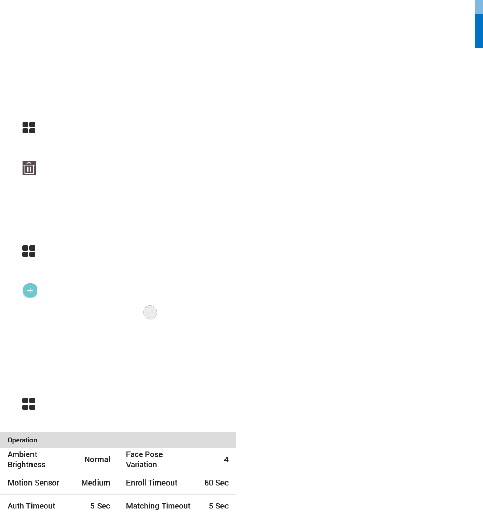
Operation
1 Press and authenticate with the Admin level credential.
2 Press AUTHENTICATION and then modify the items below Operation.
• Ambient Brightness: Detect the ambient brightness and adjust the intensity of IR LED. Change settings according to the installation
environment.
• Motion Sensor: Set the sensitivity for detecting motion near the device.
• Auth Timeout: If the authentication is not completed during the set time, the authentication will fail.
• Face Pose Variation: Set the sensitivity for the position, angle, and distance of a face when registering the face. Set high if you wish to obtain a
detailed face template
• Enroll Timeout: If a face is not registered during the set time, the face registration will be canceled.
• Matching Timeout: If the matching is not completed during the set time, the authentication will fail.
Authentication
17
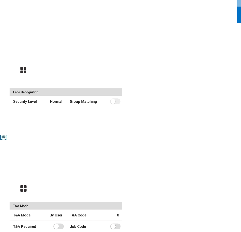
Face Recognition
Change settings regarding face authentication.
1 Press and authenticate with the Admin level credential.
2 Press AUTHENTICATION and then modify the items below Face Recognition.
• Security Level: Set the security level for 1:N authentication.
• Group Matching: Check whether or not to use Group Matching. If Group Matching is used, you can increase the authentication speed by
designing various users’ faces in a group.
• Group Matching can be set in BioStar 2. For detailed contents, refer to the BioStar 2 Administrator Manual.
T&A Mode
You can set how to register T&A Mode.
1 Press and authenticate with the Admin level credential.
2 Press AUTHENTICATION then modify the items below T&A Mode.
3 Select and set the desired item.
• T&A Mode: Set the method to use T&A mode.
• T&A Code: Register a new T&A code.
• T&A Required: Set to require a user to select a T&A event when authenticating.
• Job Code: Select whether or not to use Job Code.
Note
Network
18
Network
Network Settings
You can change the network settings of the device.
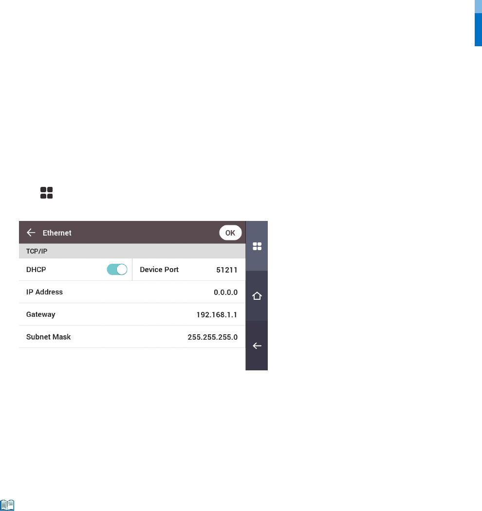
Ethernet
1 Press and authenticate with the Admin level credential.
2 Press NETWORK > Ethernet.
• DHCP: Set whether or not to use DHCP. If DHCP setting is disabled, the user can modify Device Port, IP Address, Gateway, Subnet Mask, and
DNS.
• Device Port: Set the device port.
• IP Address: View the IP address of the device. To modify, disable DHCP setting.
• Gateway: View the gateway of the device. To modify, disable DHCP setting.
• Subnet Mask: View the subnet mask of the device. To modify, disable DHCP setting.
• DNS server: Set the DNS server address. To modify, disable DHCP setting.
3 To modify network information manually, disable DHCP setting. You can modify Device Port, IP Address, Gateway, Subnet Mask
and DNS.
• Ethernet cannot be used at the same time as Wireless.
Note
Network
19
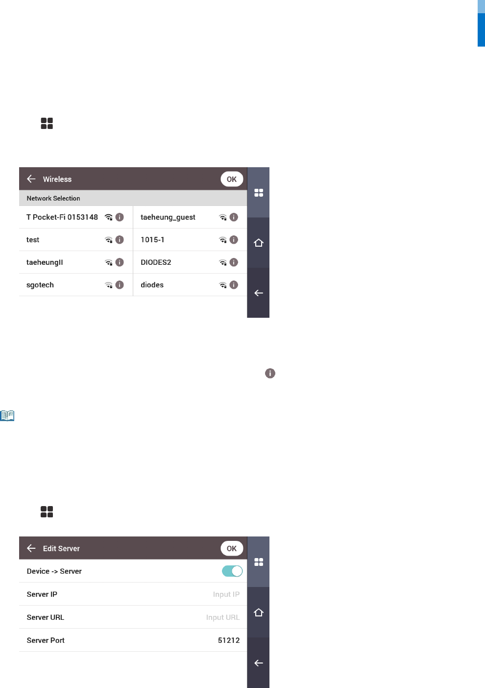
Wireless
1 Press and authenticate with the Admin level credential.
2 Press NETWORK > Wireless.
3 The list of available networks for connection will be displayed.
4 Select the network to which you wish to connect and enter the password. When you press OK, the connection to the wireless network
will be made.
5 To set the network information of the wireless LAN manually, press of the network name you wish to use and disable DHCP
setting. You can modify IP Address, Gateway, Subnet Mask and DNS.
• Wireless cannot be used at the same time as Ethernet.
• To connect to Wireless, a wireless router is required. For content regarding the installation and configuration of a wireless router, refer to the user
manual of the wireless router.
Server
1 Press and authenticate with the Admin level credential.
2 Press NETWORK > Server.
• Connection Mode: When you select Device -> Server, you can send a connection signal from the device to a server with the input information
directly. When you select Server -> Device, Server IP, Server URL and Server Port cannot be entered.
• Server IP: Enter the IP address of the PC on which BioStar 2 is installed. Input is accepted only when Device -> Server is set for Connection Mode.
• Server URL: Enter server URL instead of Server IP. Input is accepted only when Device -> Server is set for Connection Mode.
• Server Port: Enter the port of the PC on which BioStar 2 is installed. Input is accepted only when Device -> Server is set for Connection Mode.
Note
Network
20
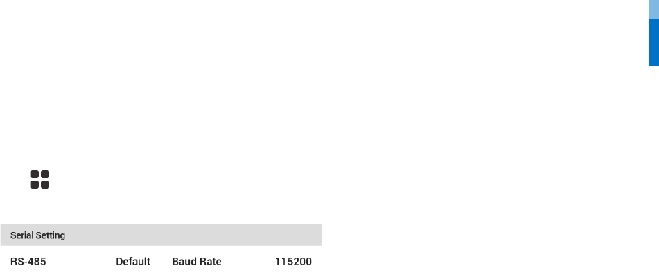
Serial Settings
RS-485
1 Press and authenticate with the Admin level credential.
2 Press NETWORK and then modify the items below Serial Setting.
• RS-485: Select the RS-485 mode.
• Baud Rate: Select the desired baud rate.
Display & Sound
21
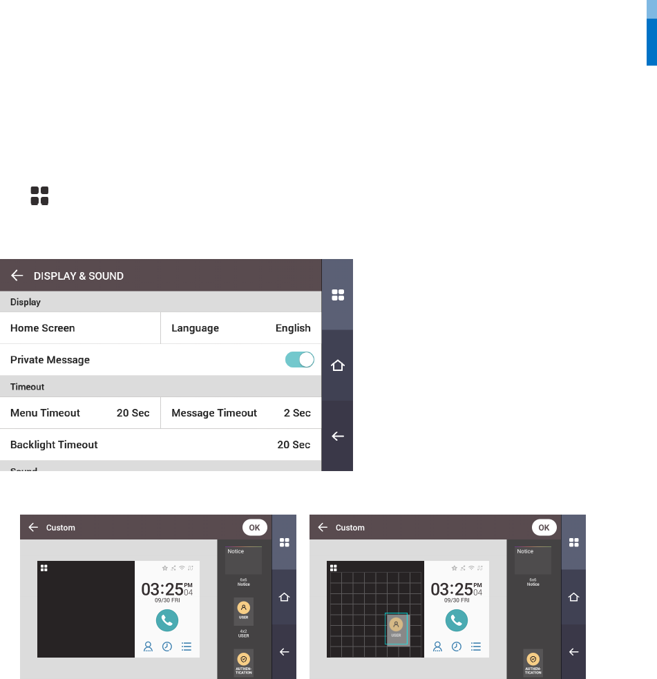
Display & Sound
You can change the display and sound settings of the device.
1 Press and authenticate with the Admin level credential.
2 Press DISPLAY & SOUND.
3 Change the desired item.
• Home Screen: Select items to be displayed in the background of the home screen. When Custom is selected for Style, the user can modify the
Home Screen directly. Edit the Home Screen by pressing and holding the desired object, then dragging and dropping it to a desired location.
• Language: Set the language you wish to use.
• Private Message: Set whether or not to use a Private Message, which will be displayed on the screen when the user authenticates.
• Menu Timeout: Set the time (in seconds) for the menu screen to disappear automatically. If there is no button input during a set time, the screen
will return to the home screen.
• Message Timeout: Set the time (in seconds) for a setting complete message or information message to disappear automatically.
• Backlight Timeout: Set the time (in seconds) to automatically turn off the lighting of the LCD screen.
• Voice Instruction: Set to use the voice instruction instead of alarm sounds.
• Volume: Set the volume.
Device
22
Device
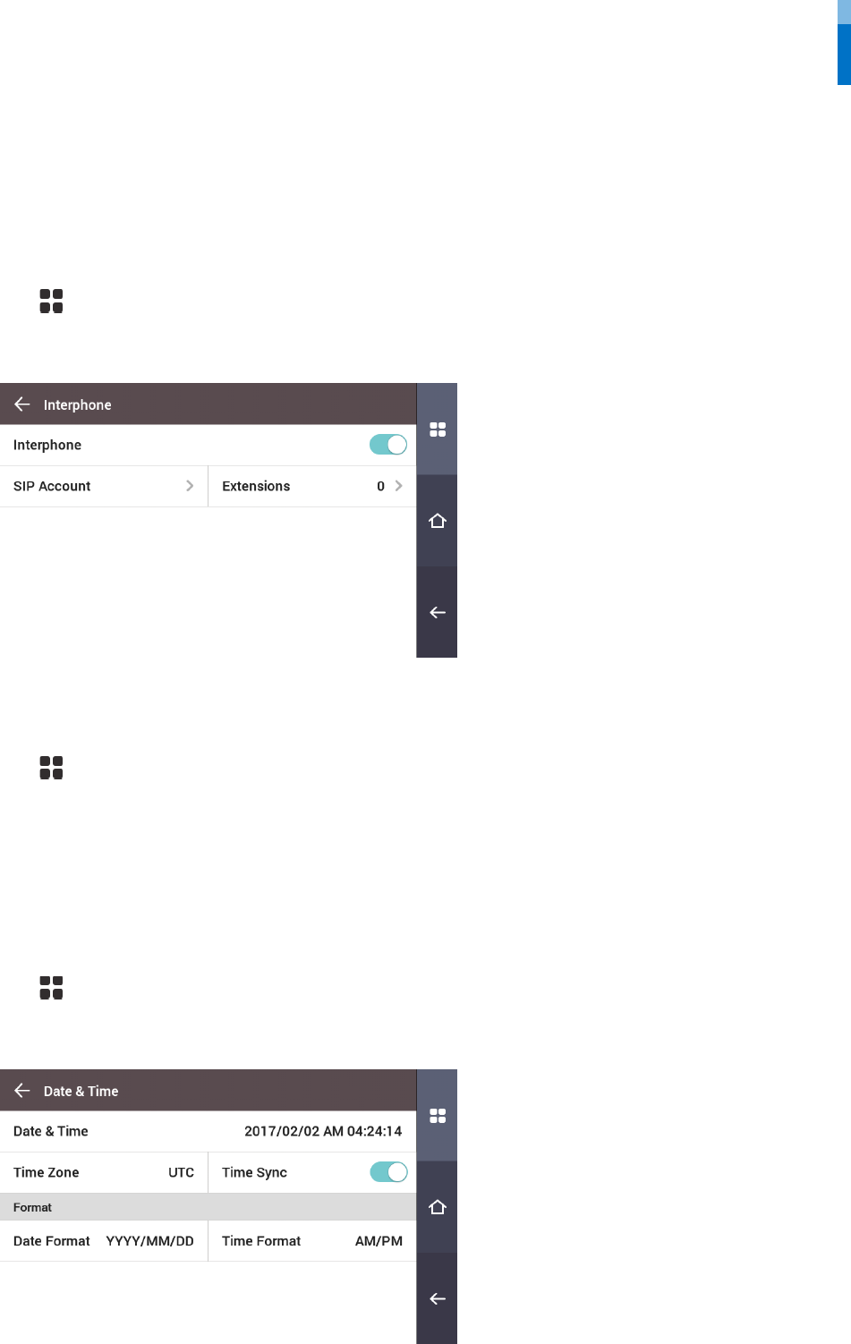
Interphone
Set the account and extensions of SIP interphone.
1 Press and authenticate with the Admin level credential.
2 Press DEVICE > Interphone.
3 When Enable is set for Interphone, you can set the SIP account and the extensions. Ensure to set each item correctly.
Relay
You can set the open time and the input port of the exit button in the device.
1 Press and authenticate with the Admin level credential.
2 Press DEVICE > Relay.
• Open Time: Set the duration for the door to remain open when standard user authentication has been carried out.
• Exit button: Select the input port where the exit button is connected.
• Switch: Select the relay type (N/O or N/C).
Date & Time
You can set date and time. Set the date and time accurately in order to collect accurate log data.
1 Press and authenticate with the Admin level credential.
2 Press DEVICE > Date & Time.
3 Change the desired item.
• Date & Time: Check the current date and time. To modify it directly, disable Time Sync.
• Standard time zone: Set the time reference of the current location.

Device
23
• Time Sync: Synchronize the server and the time. If you wish to synchronize the server and the time, enable Time Sync.
• Date Format: Set the date format. You can select among YYYY/MM/DD, MM/DD/YYYY and DD/MM/YYYY.
• Time Format: Set the time format. You can select either 24-Hour or AM/PM.
Device Info
You can view the model name, firmware version of Device ID, and MAC address.
1 Press and authenticate with the Admin level credential.
2 Press DEVICE > Device Info.
3 You can view the information including Model Name, Device ID, HW, FW, Kernel, MAC, and WiFi MAC.
Memory Info
View the status of memory usage.
1 Press and authenticate with the Admin level credential.
2 Press DEVICE > Memory Info.
USB Memory
Connect USB Memory and import user information to the device or export log and user information from the device. Upgrade the firmware.
1 Press and authenticate with the Admin level credential.
2 Press DEVICE > USB Memory.
3 Select the desired item and change the setting.
• Import: Import user information from the connected USB memory.
• Export: Select information you wish to export to the connected USB memory.
• FW Upgrade: Upgrade the firmware if the firmware files are saved in the connected USB memory.
The type of supported USB memory is as follows. If you use a different type of USB memory, the function may not operate normally.
• Samsung Electronics: SUM-LSB 8GB, SUM-PSB 8GB, SUM-PSB 16GB, SUM-BSG 32GB
• LG Electronics: XTICK J3 WINDY 8GB, SMART USB MU1 White 8GB, MU 1 USB 32GB, MU28GBC 32GB, XTICK MOBY J1 16GB
• SanDisk: Cruzer 16GB, Cruzer Blade CZ50 4GB, Cruzer Blade CZ50 32GB, CZ48 Ultra USB 3.0 64GB, CZ80 USB3.0 64GB, CZ52 64GB, Cruzer Glide Z60
128GB, Cruzer Force CZ71 32GB
• Sony: Micro Vault Click 8GB, MicroVault CLICK 16GB, USM-SA1 32GB
• Transcend: JetFlash 760 8GB, JetFlash 760 32GB, JetFlash 500 8GB
• Memorette: MINI500 8GB
• A-DATA: S102 PRO 8GB
• Trigem Pastel 8GB
Restart Device
The user can restart the device.
1 Press and authenticate with the Admin level credential.
2 Press DEVICE > Restart Device.
3 To restart the device, press OK. To cancel, press Cancel.
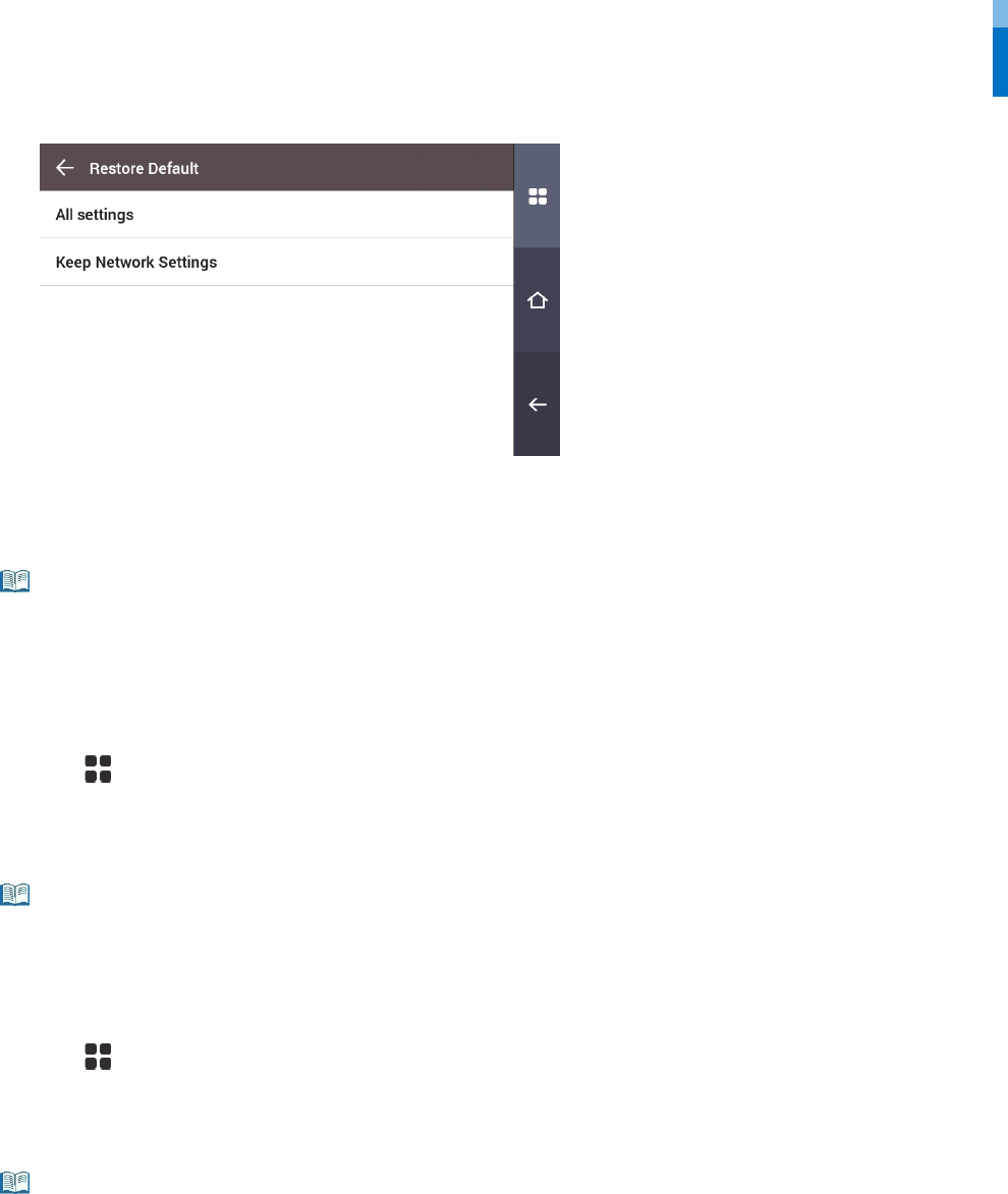
Restore Default
Device settings, network settings, and operator levels will be reset.
1 Press and authenticate with the Admin level credential.
2 Press DEVICE > Restore Default.
Note
Device
24
3 To reset all device settings, select All settings and press OK. To reset all settings except for network settings, select Keep Network
Settings and press OK.
• When you reset, the operator level will be reset as well. After resetting, make sure to set the operator level again.
• Language setting will not change after resetting.
Factory Default
Delete all the information saved in the device and the root certificate and restore default settings.
1 Press and authenticate with the Admin level credential.
2 Press DEVICE > Factory Default.
3 To reset, press OK.
• Factory Default menu can be used when the root certificate is saved in the device.
Delete the Root Certificate
Delete the root certificate saved in the device.
1 Press and authenticate with the Admin level credential.
2 Press DEVICE > Delete the Root Certificate.
3 To delete the Root Certificate, press OK.
• Delete the Root Certificate menu can be used only when the root certificate is saved in the device and Administrator has been designated.
Note
Note
Note
Event Log
25
Event Log
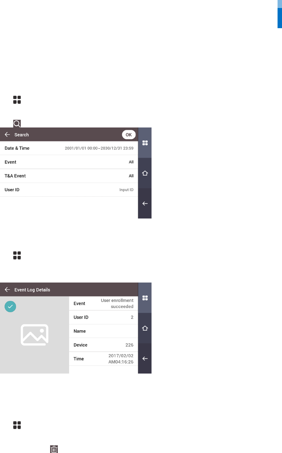
Search Log
You can set a condition and search a log.
1 Press and authenticate with the Admin level credential.
2 Press EVENT LOG.
3 Press and change the condition. When you press OK, a log that matches the condition will be displayed on the screen.
Detail View Log
1 Press and authenticate with the Admin level credential.
2 Press EVENT LOG.
3 Select a log to view detailed contents.
Delete All Logs
You can delete all saved logs.
1 Press and authenticate with the Admin level credential.
2 Press EVENT LOG.
3 To delete all logs, press and then press OK. To cancel, press Cancel.
Event Log
26
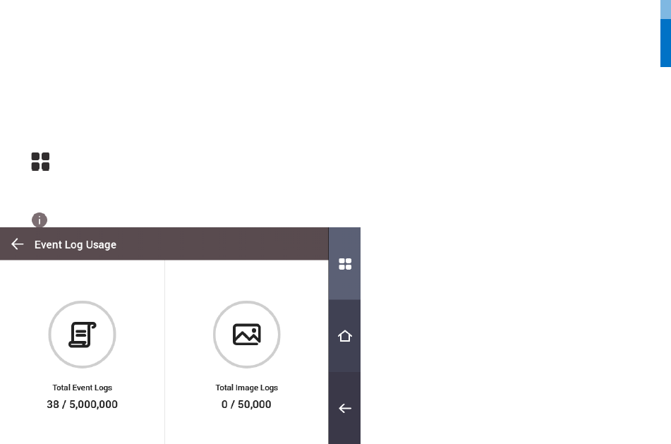
View Log Usage
You can check the status of log usage.
1 Press and authenticate with the Admin level credential.
2 Press EVENT LOG.
3 Press .
Troubleshooting
27
Troubleshooting
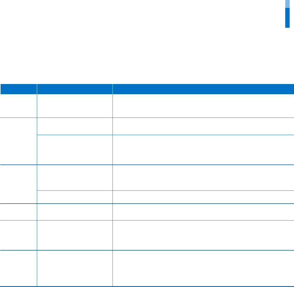
Checklist before reporting a failure
Classification Problem Solution
Power The power is being supplied but
the device does not operate.
• If the distance between the terminal and the bracket is too great, the device
may not operate due to the temper switch.
• Check the adaptor or the power cable.
PIN
I forgot my PIN. • For a normal user PIN, request it from the administrator and reenter the PIN.
• If you have lost the Admin PIN, contact the installation company.
I entered my PIN and pressed the
OK button, but I still cannot
open the door.
• Check if you entered the registered PIN correctly.
• Check if you have changed your PIN recently.
• If you cannot remember the PIN, request it from the administrator and reenter
the PIN.
Face
The face has been registered but
face authentication cannot be
done smoothly, and errors occur
frequently.
• Check ‘Cautions for registering a face’ and register the face again.
• If there are a large number of registered faces, change Matching Timeout and
try again.
Face authentication has
suddenly stopped working.
• Check ‘Cautions for authenticating a face’ and try again.
Door Lock The door does not lock
when I close the door.
• The electric lock may be malfunctioning. Have an inspection performed by the
installation company.
Time The time has suddenly become
incorrect.
• FaceStation 2 is equipped with a built-in battery; however, if power is not
supplied for a long period of time, the built-in battery may die, causing the time
to become incorrect. For information on correcting the time, referring to Date &
Time.
Admin
Access
I lost my Admin PIN, so I cannot
access the Admin mode.
• The administrator grants access permission in FaceStation 2, so only the
administrator can access the Admin menu.
• If you need to access the Admin menu, you can have a PIN issued through a
special procedure. Ask the installation company for the procedure to issue the
password.

Product specifications
28
Product specifications
Category Feature Specification
Credential
Biometric
Face
RF Option
•FS2-D: EM, MIFARE, MIFARE Plus, DESFire/EV1, FeliCa, NFC, ISO14443A, ISO15693
•FS2-AWB: EM, HID Prox, MIFARE, MIFARE Plus, DESFire/EV1, FeliCa, iCLASS SE/SR, NFC, BLE,
ISO14443A, ISO15693
RF read range*
MIFARE/DESFire/iCLASS/ISO15693 : 50 mm / EM/HID Prox/Felica: 30 mm, BLE: 50 mm
LFD
Supported
General
CPU
1.4 GHz Quad Core
Memory
8GB Flash + 1GB RAM
LCD type
4” color TFT touch
LCD resolution
800 x 480
Sound
24 bit/Voice DSP (echo cancel)
Operating temperature
-20 °C - 50 °C
Storage temperature
-40 °C - 70 °C
Operating humidity
0% - 80%, non-condensing
Storage humidity
0% - 90%, non-condensing
Camera type
CMOS
Camera resolution
720 x 480
Camera angle
Visual Lens: Diagonal 92.7°
IR Lens: Diagonal 58°
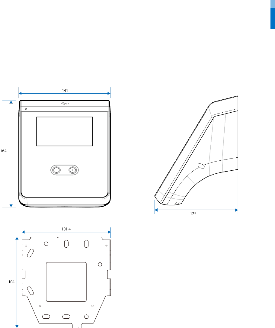
Dimension (W x H x D)
141 mm x 164 mm x 125 mm
Weight
Device: 628 g
Bracket: 74 g (Including washer and bolt)
Certificates
CE, FCC, KC, RoHS, REACH, WEEE
Capacity
Max. User (1:1)
30,000
Max. User (1:N)
3,000
Max. Template (1:1)
900,000
Max. Template (1:N)
90,000
Max. Text Log
5,000,000
Max. Image Log
50,000
Interface
Wi-Fi
Supported (Built-in, IEEE802.11 b/g/n)
Ethernet
Supported (10/100/1000 Mbps, auto MDI/MDI-X)
RS-485
1ch Host or Slave (Selectable)
Wiegand
1ch Input, 1ch Output
TTL input
1ch Input
Relay
1 Relay
USB
USB 2.0 (Host)
Tamper
Supported
Electrical
Power
Voltage: 12 VDC
Current: Max. 2.5 A
Switch input VIH
Min.: 3 V
Max.: 5 V
Switch input VIL
Max.: 1 V
Switch Pull-up resistance
4.7 kΩ (The input pots are pulled up with 4.7 kΩ.)
Wiegand output VOH
More than 4.8 V
Wiegand output VOL
Less than 0.2 V
Wiegand output Pull-up resistance
Internally pulled up with 1 kΩ
Relay
Voltage: Max. 30 VDC
Current: Max. 1 A
* RF read range will vary depending on installation environment.
Product specifications
29
Dimensions
(Unit: mm)

FCC compliance information
30
FCC compliance information
THIS DEVICE COMPLIES WITH PART 15 OF THE FCC RULES.
Operation is subject to the following two conditions:
(1) This device may not cause harmful interference, and
(2) This device must accept any interference received, including interference that may cause undesired operation.
Note: This equipment has been tested and found to comply with the limits for a Class B digital device, pursuant to part 15 of the FCC Rules.
These limits are designed to provide reasonable protection against harmful interference in a residential installation. This equipment
generates, uses, and can radiate radio frequency energy and, if not installed and used in accordance with the instructions, may cause
harmful interference to radio communications. However, there is no guarantee that interference will not occur in a particular installation. If
this equipment does cause harmful interference to radio or television reception, which can be determined by turning the equipment off
and on, the user is encouraged to try to correct the interference by one or more of the following measures:
• Reorient or relocate the receiving antenna.
• Increase the separation between the equipment and receiver.
• Connect the equipment to an outlet on a circuit different from that to which the receiver is connected.
• Consult the dealer or an experienced radio/TV technician for help.
Modifications not expressly approved by the manufacturer may void the user's authority to operate the equipment under FCC rules.
This appliance and its antenna must not be located or operated in conjunction with any other antenna or transmitter.
A minimum separation distance of 20cm must be maintained between the antenna and individuals for this appliance to satisfy the RF
exposure requirements.
EU Declaration of Conformity (CE)
This product is CE marked according to the provisions of the R&TTE Directive (1999/5/EC).
Suprema Inc. hereby declares that this product is in compliance with the essential requirements and other relevant provisions of Directive
1999/5/EC. This device is a class 1 radio device according to the directive.
For more information, contact us using the following contact information.
Suprema Inc.
Website: https://www.supremainc.com
Address: Parkview Tower F16, 248, Jeongjail-ro, Bundang-gu, Seongnam-si, Gyeonggi-do, Korea (Jeongja-dong 6)
Tel: 031-783-4510 / Fax: 031-783-4517

Appendices
31
Appendices
Escape clause
• The information in this manual is provided with regard to Suprema products.
• The right to use is acknowledged only for products included in the terms and conditions of the sales agreement guaranteed by
Suprema. The right of license to other intellectual property rights not discussed in this manual is not acknowledged.
• Suprema does not guarantee or hold responsibility for the suitability and commerciality of the product for a specific purpose, or the
infringement of patent, copyright, or other intellectual property rights with regard to sales or usage of Suprema products.
• Do not use a Suprema product in situations related to medical, rescue of human lives, or maintenance of life, as a person may be injured
or killed due to product malfunction. If an accident occurs while a consumer is using the product under the situations described as
examples above, employees, subsidiaries, branches, affiliated companies, and distributors of Suprema do not accept responsibility, nor
will they be liable for all related direct and indirect expenses or expenditures, including attorney fees, even if the consumer has
discovered shortcomings in the product design or manufacturing process and claims this as a significant fault.
• Suprema may modify the product size and specifications at any time without proper notice in order to improve the safety, function, and
design of the product. Designers must keep in mind that functions or descriptions indicated as "to be implemented" or "undefined"
may change at any time. Suprema will implement or define such functions or descriptions in the near future, and Suprema accepts no
responsibility for compatibility issues and any other problems arising from such compatibility issues.
• If you wish to obtain the newest specifications before ordering the product, contact Suprema through a Sales Representative or local
distributor of Suprema.
Copyright notice
The copyright of this document is vested in Suprema. The rights of other product names, trademarks, and registered trademarks are vested
in each individual or organization that owns such rights.

www.supremainc.com
www.supremainc.com