User Manual
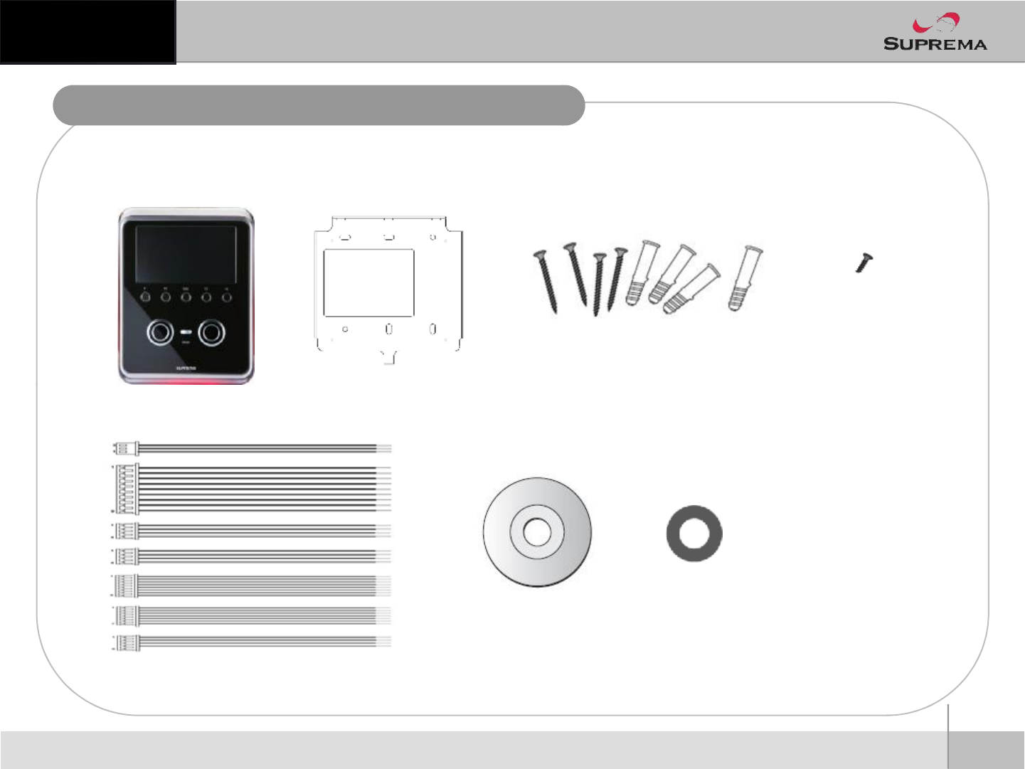
Product Contents
nBasic Contents
Product Contents
Wallmounting
screwsand holders-4 ea
Screw for fixing main body
2
ⒸCopyright 2010Suprema Inc.
Terminal Wall mounting metal bracket
Cables
Software CD
Ferrite Core
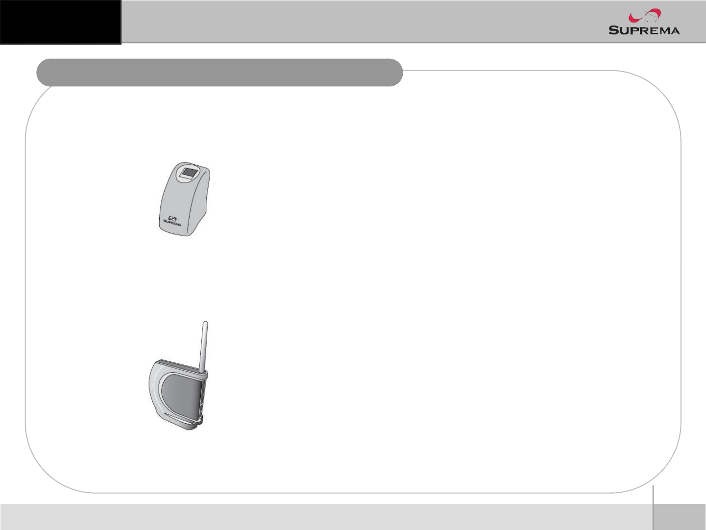
Product Contents
nOptional accessories
USB fingerprint scanner f
3
ⒸCopyright 2010Suprema Inc.
USB fingerprint scanner f
or enrollmenton PC
Wireless LAN Access Point
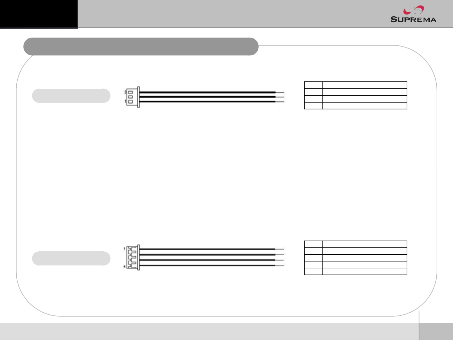
Cable and Connector Pinout
Relay
PIN PIN DESCRIPTION
1NORMAL OPEN
2 COMMON
3NORMAL CLOSE
4
ⒸCopyright 2010Suprema Inc.
RS485
PIN PIN DESCRIPTION
1TRX -
2TRX +
3GND
4 SHIELD GND
Before Start
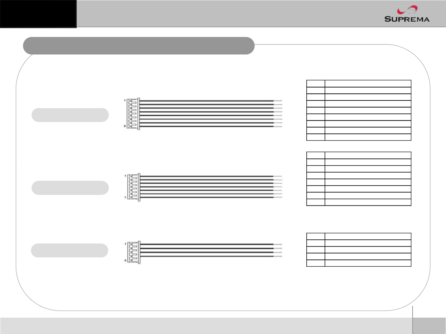
Cable and Connector Pinout
Switch Input
PIN PIN DESCRIPTION
1SWIN_IN0
2 SWIN_IN1
3GND
4 SHIELD_GND
5 SWIN_IN2
6 SWIN_IN3
7GND
8 SHIELD_GND
PIN PIN DESCRIPTION
1VDP_S
2
GND
5
ⒸCopyright 2010Suprema Inc.
VDP
Wiegand
Before Start
PIN PIN DESCRIPTION
1WIEGAND_D0
2WIEGAND_D1
3GND
4 SHIELD GND
2
GND
3 VDP_VCC
4 VDP_V
5VDP_OPEN
6GND
7 SHIELD_GND
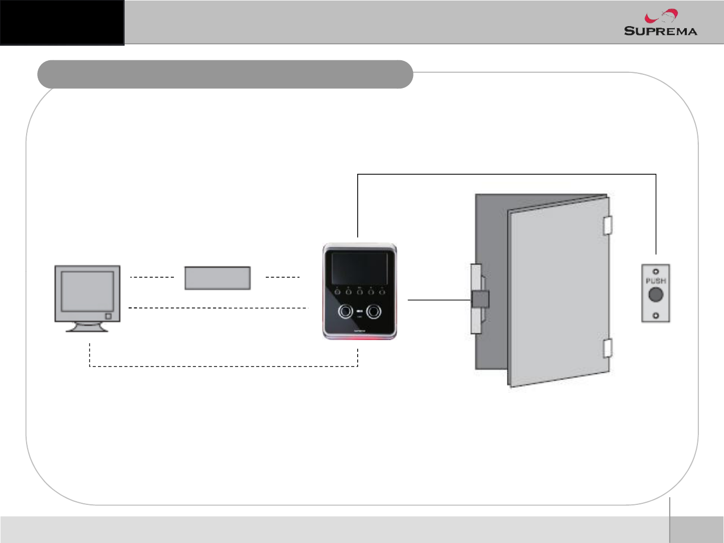
Installation Example
PC Network HUB
8P Cable
Ethernet
6
ⒸCopyright 2010Suprema Inc.
Exit Button
Door Lock
3P Cable
USBUSB Firmware
Upgrade Only
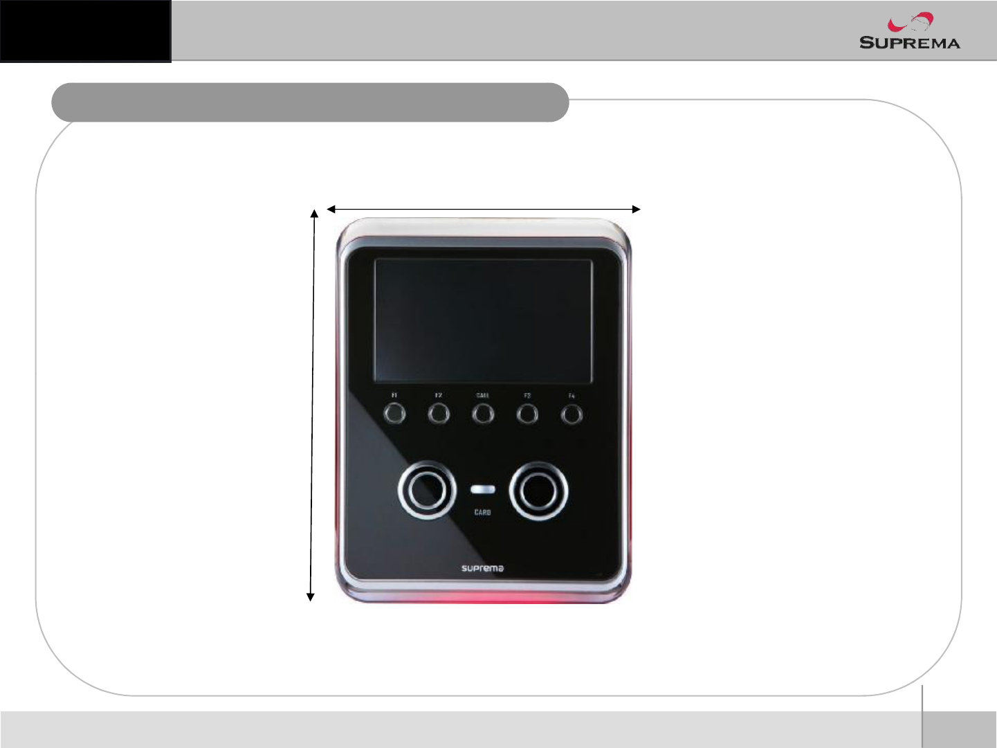
Product Dimension
132
7
ⒸCopyright 2010Suprema Inc.
Front
165
(unit : mm)
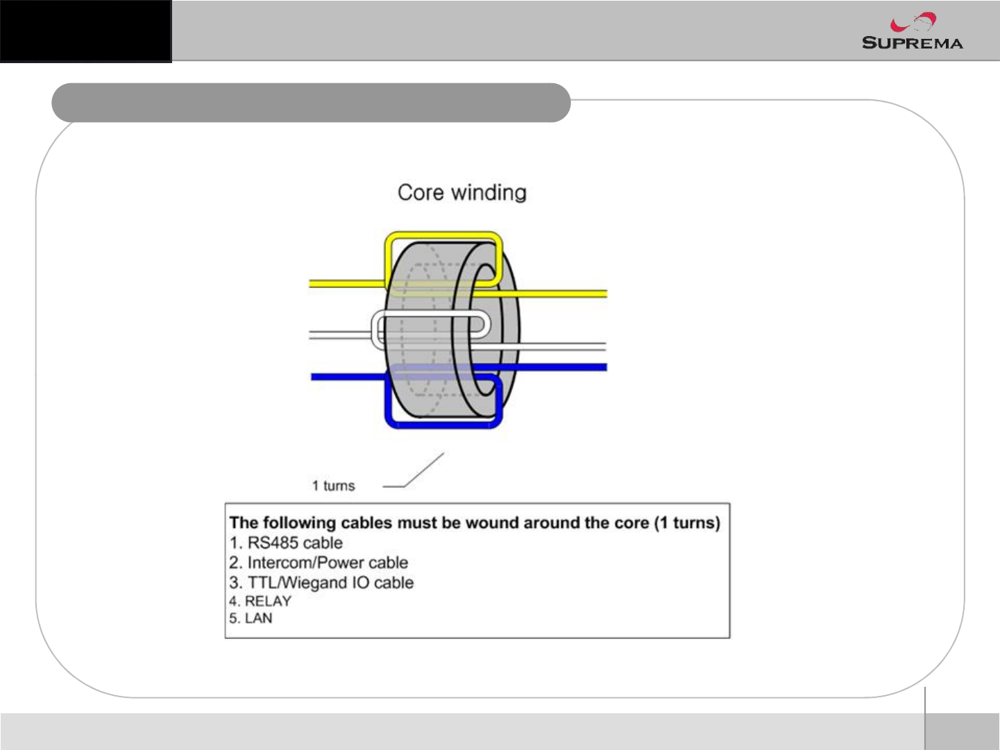
Ferrite Core 사용법
8
ⒸCopyright 2010Suprema Inc.
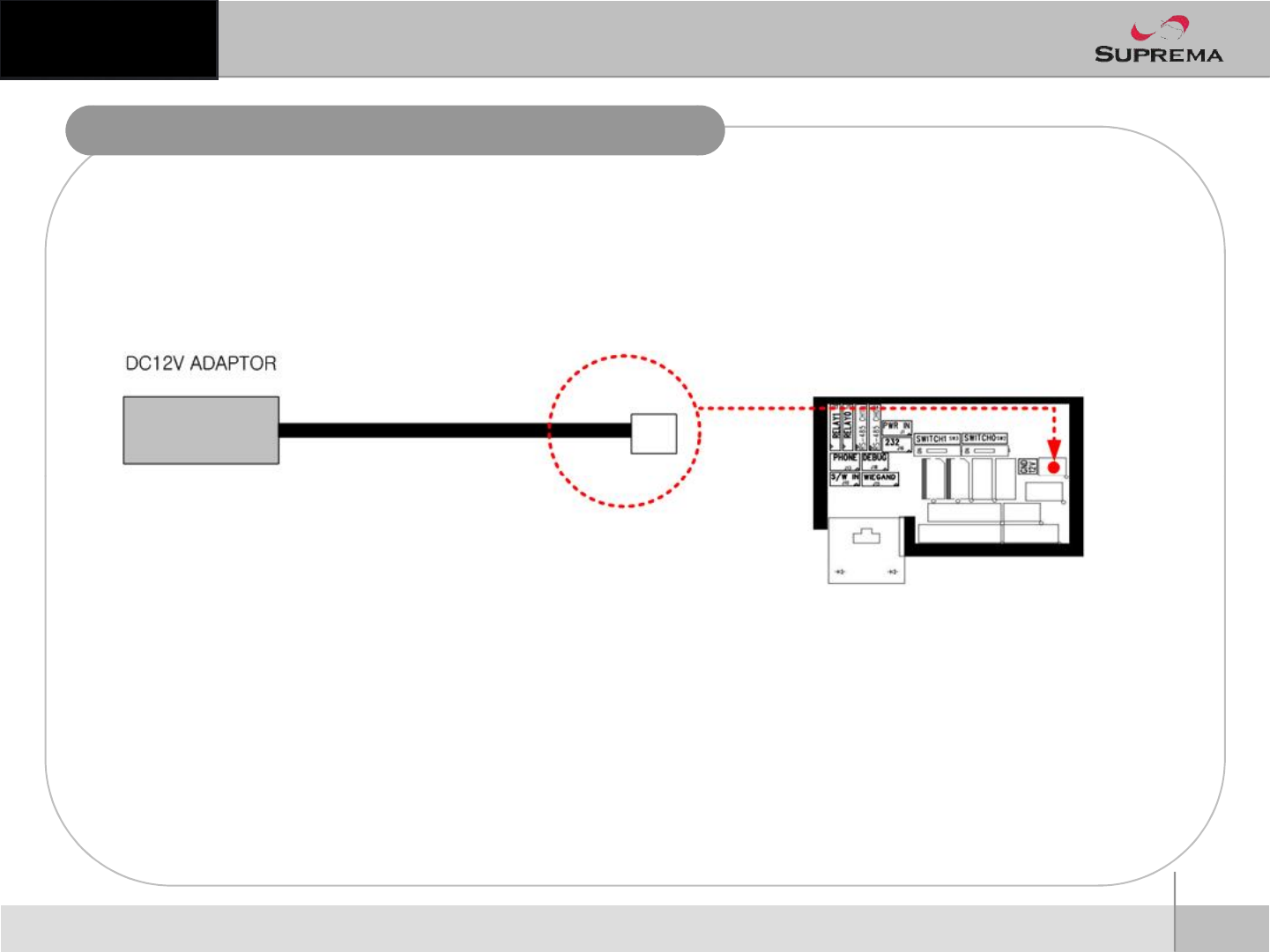
전원연결
nPower Connection
9
ⒸCopyright 2010Suprema Inc.
nRecommended
l12V ±10%, at least 1500mA for BioStation T2 alone installation.
lComply with standard IEC/EN 60950-1
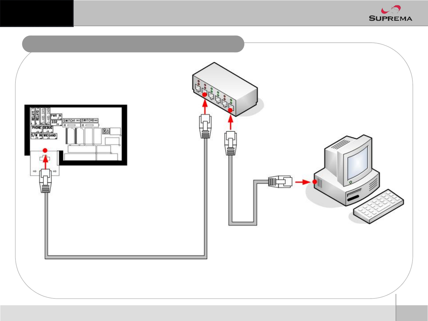
LAN Connection
10
ⒸCopyright 2010Suprema Inc.
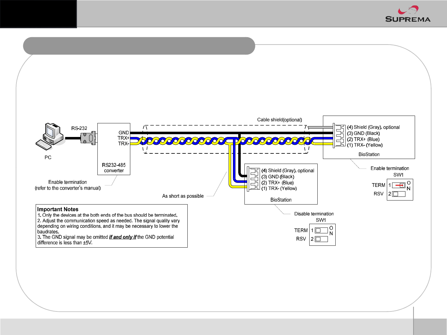
RS485 Network Connection
11
ⒸCopyright 2010Suprema Inc.
Before Start
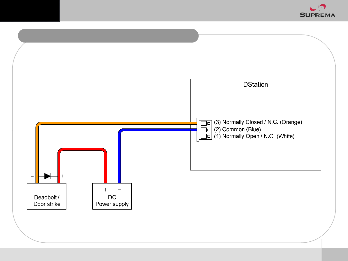
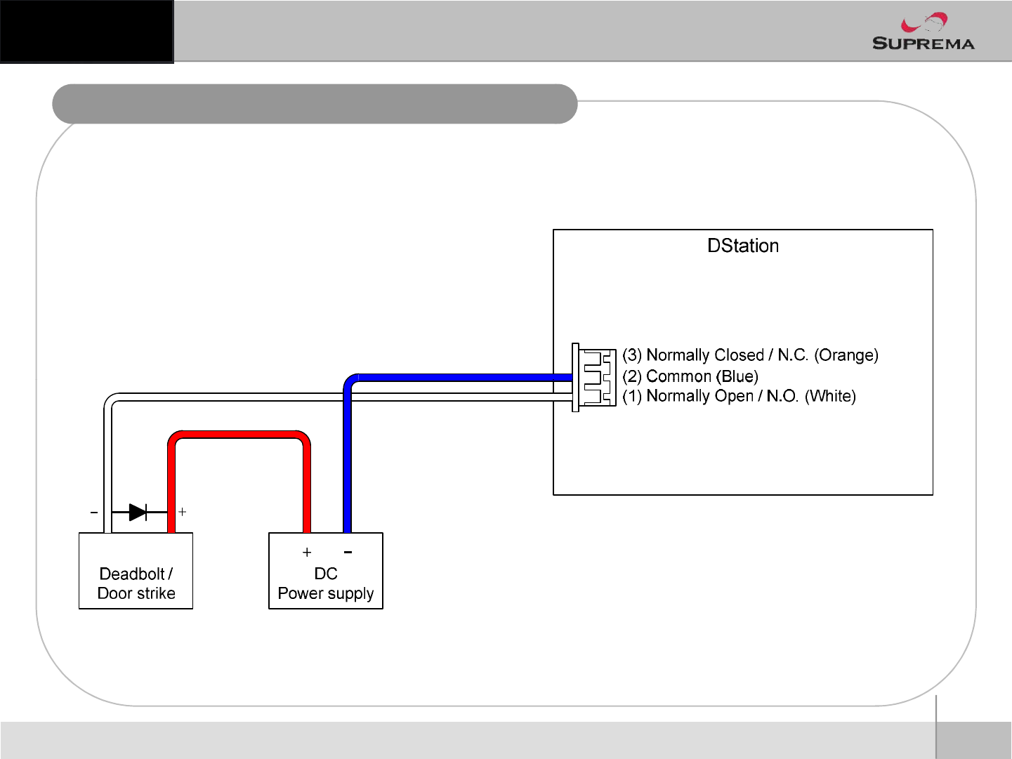
Relay Connection –Fail Safe Lock
12
ⒸCopyright 2010Suprema Inc.
Relay Connection –Fail Secure Lock
13
ⒸCopyright 2010Suprema Inc.
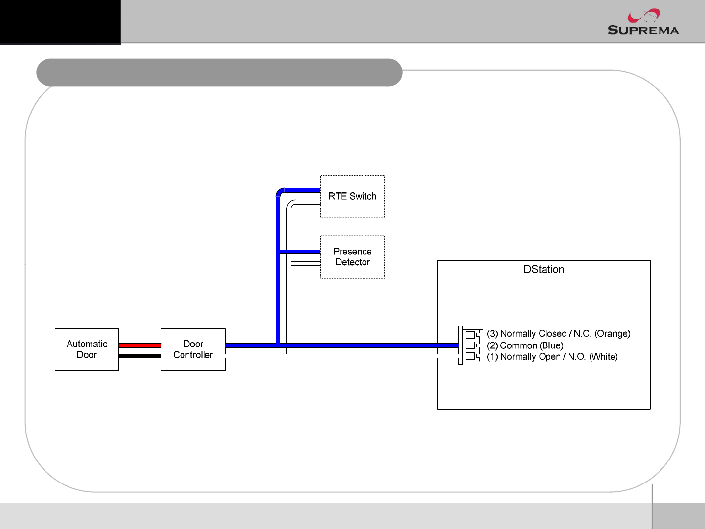
Relay Connection -Automatic Door
14
ⒸCopyright 2010Suprema Inc.
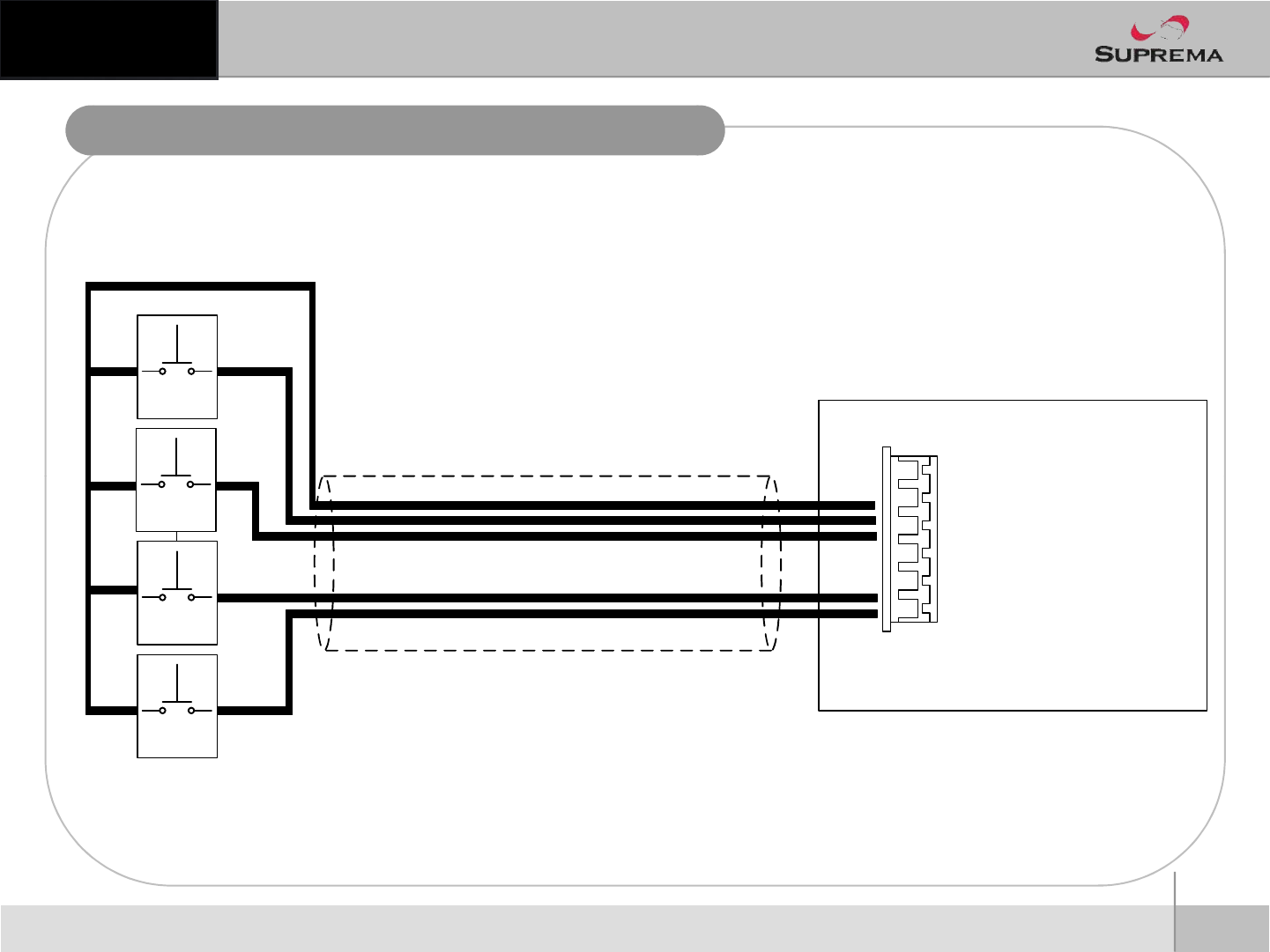
TTL Input Port Connection –RTE Switches
DStation
Cable shield(optional)
(
8
)
SHELD
GND
Request
To Exit #1
15
ⒸCopyright 2010Suprema Inc.
(1) TTL IN0
(2) TTL IN1
(5) TTL IN2
(6) TTL_IN3
(3) GND
(2) SHELD_GND
(7) GND
(
8
)
SHELD
_
GND
Request
To Exit #1
Request
To Exit #1
Request
To Exit #1
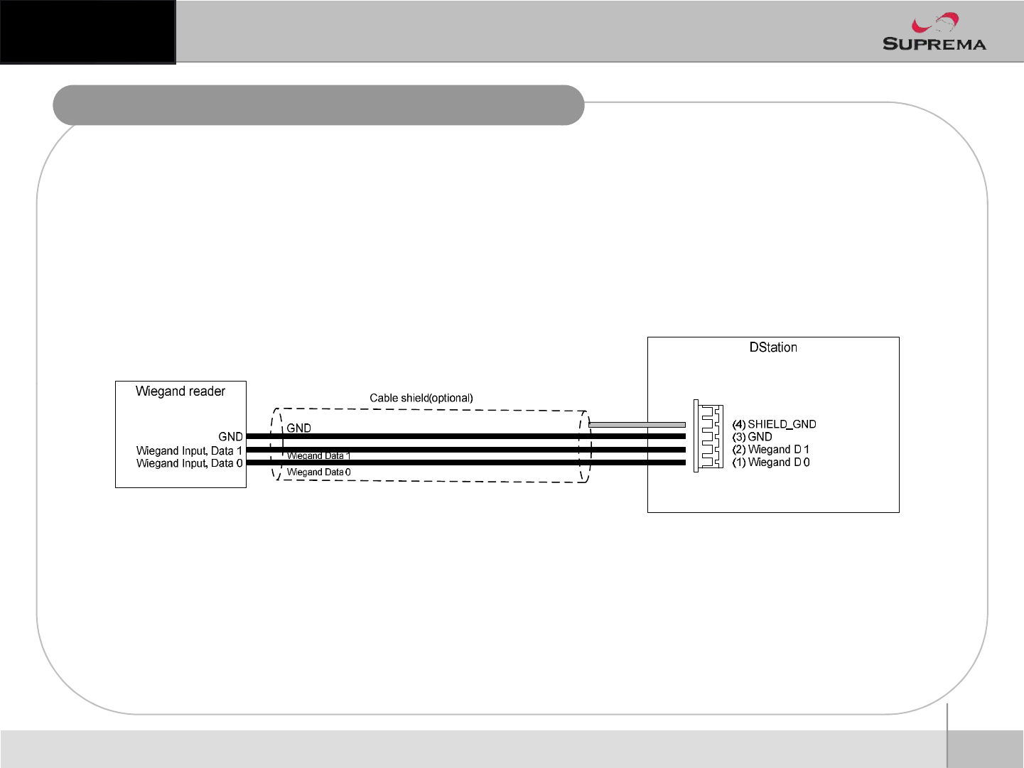
Wiegand Input Connection –External reader
16
ⒸCopyright 2010Suprema Inc.

System Specifications
n●CPU :Main B/D CPU -ARM11 667MHz X 1ea
n-DSP 1GHz X 1ea
n
n●Memory : Main B/D -Flash : Nand SLC 512MByte, SDRAM(mDDR) : 256MByte
n
n●DISPLAY : 4.3inch LCD X 1ea
n●INPUT : 저항막방식 Touch Screen X 1ea + 5 Keypad (F1~F4, CALL)
n●CAMERA : VGA CMOS Camera X 2ea
n●I/O Port : Wiegand In/Out (S/W 설정을통해 Input 또는 Output으로사용가능) X 1ch
nSwitch Input X 4ch
nRS-485 X 2ch
n
RS
-
232(Share with RS
-
485) X 1ch
17
ⒸCopyright 2010Suprema Inc.
n
RS
-
232(Share with RS
-
485) X 1ch
nRelay(1A@30Vdc) X 2ch
nEthernet(10/100M) X 1ch
n●Sound Out: System Sound용Speaker X 2ea
n●RF CARD : Mifare
n●Power Input : 12Vdc Adaptor or POE Input
기타
FCC Rules
Changes or modifications not expressly approved by the manufacturer
responsible for compliance could void the user’s authority to operate the
equipment.
Caution
Warning This device complies with part 15 of the FCC Rules. Operation is subject to the
following two conditions: (1) This device may not cause harmful interface, and
(2) this device must accept any interface received, including interference that
may cause undesired operation.
Information to User This equipment has been tested and found to comply with the limit of a Class B
digital device, pursuant to Part 15 of the FCC Rules. These limits are designed
18
ⒸCopyright 2010Suprema Inc.
digital device, pursuant to Part 15 of the FCC Rules. These limits are designed
to provide reasonable protection against harmful interference in a residential
installation. This equipment generates, user and can radiate radio frequency
energy and, if not installed and used in accordance with the instructions, may
cause harmful interference to radio communications.
However, there is no guarantee that interference will not occur in a particular
installation; if this equipment does cause harmful interference to radio or
television reception, which can be determined by turning the equipment off and
on, the user is encouraged to try to correct the interference by one or more the
following measures:
1. Reorient / Relocate the receiving antenna.
2. Increase the separation between the equipment and receiver.
3. Connect the equipment into an outlet on a circuit difference from that to
which the receiver is connected.
4. Consult the dealer or an experienced radio/TV technician for help
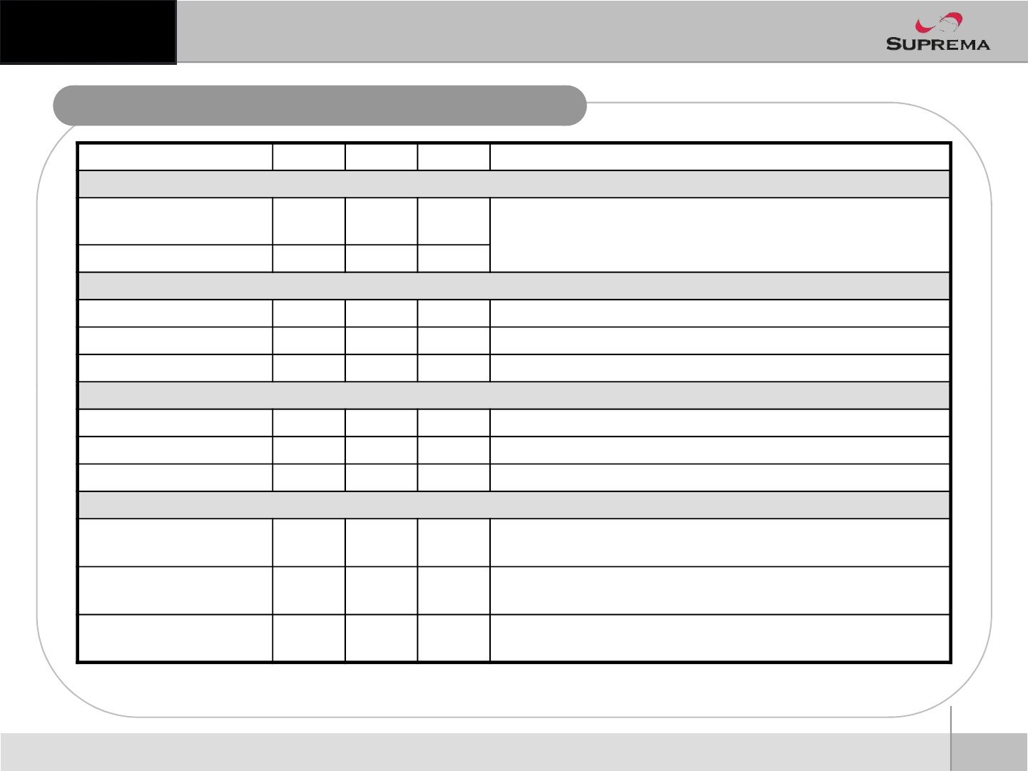
Electrical Specification
Min. Typ. Max. Notes
Power
Voltage (V) 10.8 12 13.2
Current (mA) -700
TTL/Wiegand Input
VIH (V) 2 - -
VIL (V) - - 0.8
Pull-up resistance (Ω)-10k -
19
ⒸCopyright 2010Suprema Inc.
TTL/Wiegand Output
VOH (V) 4 - - @ IOH = -5mA
VOL (V) - - 1 @ IOL = 5mA
Output resistance (Ω)-100 -
Relay
Switching capacity (A) - - 1
0.3
30V DC
125V AC
Switching power
(resistive) - - 30W
37.5VA
DC
AC
Switching voltage (V) - - 110
125
DC
AC

Suprema Inc.
16F Parkview Office Tower, Jeongja-dong, Bundang-gu,
Seongnam, Gyeonggi, 463-863 Korea
E-mail : support@supremainc.com
Website : www.supremainc.com
Functions and specifications of the product are subject to changes without notice due to quality
enhancement or function update. For any inquiry on the product, please contact Suprema Inc.