Suzhou Switek Electronics and Technology AS-41DA DVI switcher User Manual
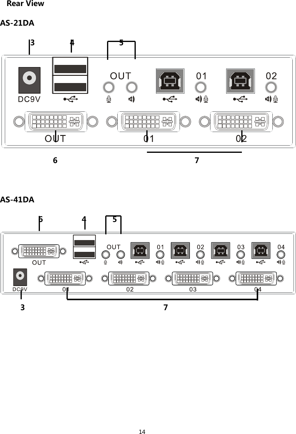
Suzhou Switek Electronics & Technology Co., Ltd. DVI switcher Users Manual
UserManual.wiki
>
Suzhou Switek Electronics and Technology
>
AS 41DA User Manual
Users Manual
Navigation menu
Upload a User Manual
Namespaces
Wiki Guide
HTML
PDF
Info
Views
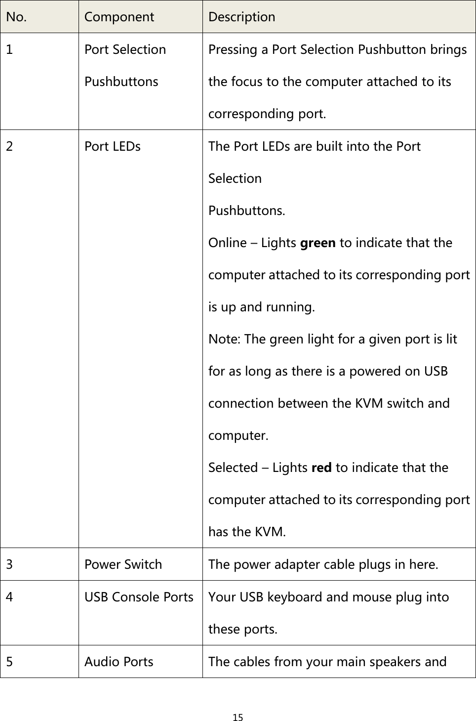
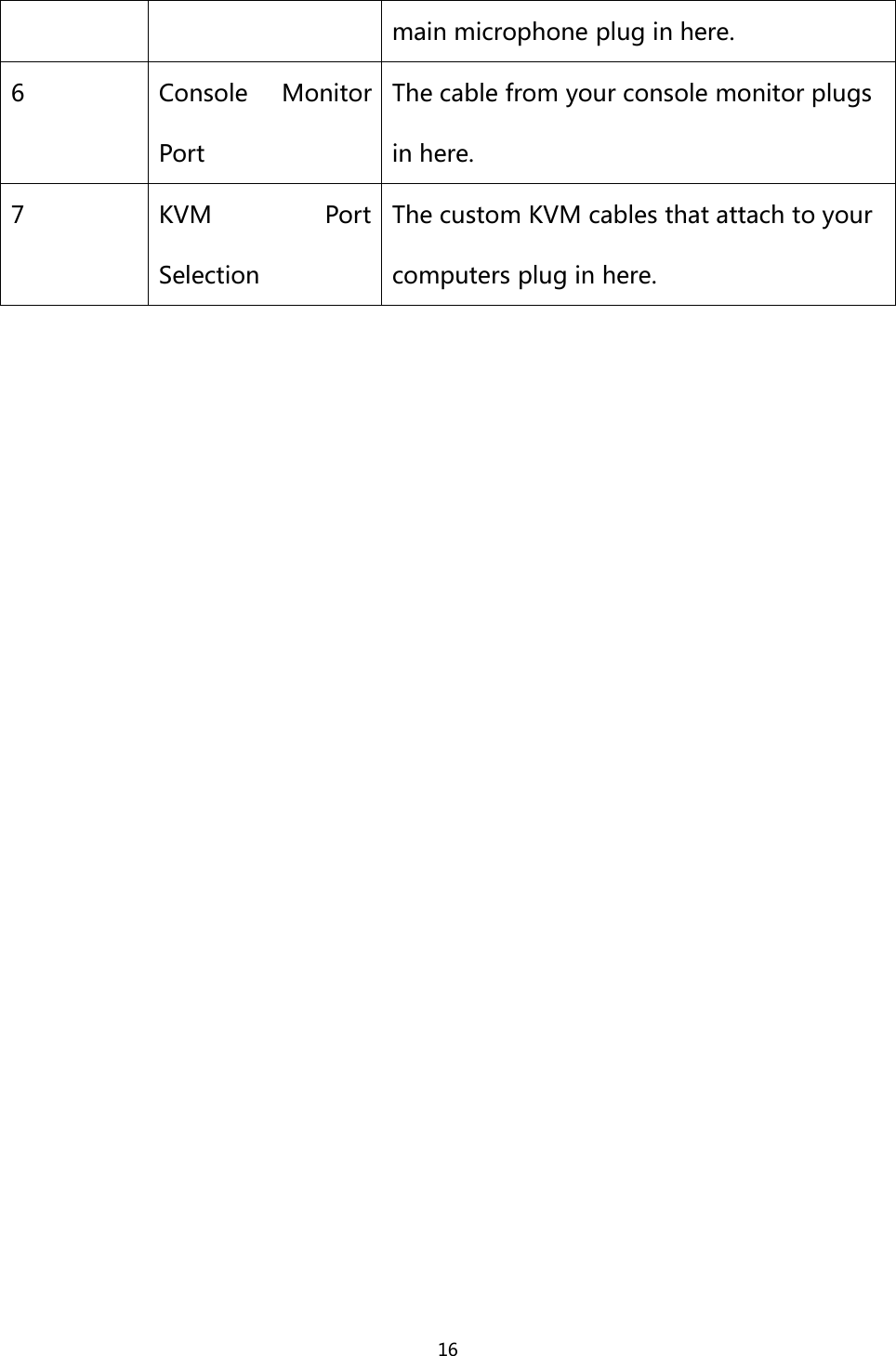
User Manual
Discussion / Help
Navigation