Suzhou Switek Electronics and Technology AS-41DA DVI switcher User Manual
Suzhou Switek Electronics & Technology Co., Ltd. DVI switcher Users Manual
Users Manual
1
USB DVI KVM Switch
AS-21DA / AS-41DA
User Manual
2
FCC Information
This equipment has been tested and found to comply with the limits for a Class
B digital device, pursuant to Part 15 of the FCC Rules. These limits are designed
toprovidereasonableprotectionagainst harmful interference in a residential
installation. This equipment generates, uses and can radiate radio frequency
energy, and if not installed and used in accordance with the instruction manual,
may cause interference to radio communications.
However, there is no guarantee that interference will not occur in a particular
installation. If this equipment does cause harmful interference to radio or
television reception, which can be determined by turning the equipment off
and on, the user is encouraged to try to correct the interference by one or more
of the following measures:
Reorient or relocate the receiving antenna;
Increase the separation between the equipment and receiver;
Connect the equipment into an outlet on a circuit different from that which
the receiver is connected;
Consult the dealer/an experienced radio/television technician for help.
RoHS
This product is RoHS compliant.
3
User Information
User Notice
All information, documentation, and specifications contained in this manual are
subject to change without prior notification by the manufacturer. The
manufacturer makes no representations or warranties, either expressed or
implied, with respect to the contents hereof and specifically disclaims any
warranties as to merchantability or fitness for any particular purpose. Any of
the manufacturer's software described in this manual is sold or licensed
as is
.
Should the programs prove defective following their purchase, the buyer (and
not the manufacturer, its distributor, or its dealer), assumes the entire cost of all
necessary servicing, repair and any incidental or consequential damages
resulting from any defect in the software.
The manufacturer of this system is not responsible for any radio and/or TV
interference caused by unauthorized modifications to this device. It is the
responsibility of the user to correct such interference.
The manufacturer is not responsible for any damage incurred in the operation
of this system if the correct operational voltage setting was not selected prior
to operation. PLEASE VERIFY THAT THE VOLTAGE SETTING IS
CORRECT BEFORE USE.
Package Contents
The AS-21DA / AS-41DA package consists of:
4
1 AS-21DA / AS-41DA USB DVI KVM Switch
1PowerCord
1 User Instructions*
Check to make sure that all of the components are present and in good order.
If anything is missing, or was damaged in shipping, contact your dealer.
Read this manual thoroughly and follow the installation and operation
procedures carefully to prevent any damage to the switch or to any other
devices on the AS-21DA / AS-41DA installation.
*Features may have been added to the AS-21DA / AS-41DA since this manual
was printed. Please visit our website to download the most up to date version
of the manual.
5
© Copyright 2012–2013 LANBE® International Co., Ltd.
LANBE and the LANBE logo are registered trademarks of LANBE Co., Ltd. All rights
reserved.
All other brand names and trademarks are the registered property of their respective
owners.
6
About This Manual
This User Manual is provided to help you get the most from your AS-21DA /
AS-41DA system. It covers all aspects of installation, configuration an operation.
An overview of the information found in the manual is provided below.
Overview
Introduction, introduces you to the AS-21DA / AS-41DA System. Its purpose,
features and benefits are presented, and its front and back panel components
are described.
Hardware Preparative Procedure, provides step-by-step instructions for
setting up your installation.
Operation, explains the concepts involved in operating the AS-21DA /
AS-41DA.
An Appendix, provides specifications and other technical information
regarding the AS-21DA / AS-41DA.
7
Contents
Introduction............................................................................................................................6
Overview................................................................................................................................................ 6
Features.................................................................................................................................................. 6
Requirements........................................................................................................................................7
Console...........................................................................................................................................7
Computers.....................................................................................................................................7
Operating Systems......................................................................................................................7
Components..........................................................................................................................................8
Front View......................................................................................................................................8
Rear View....................................................................................................................................... 9
Hardware Preparative Procedure...................................................................................11
Before You Use...................................................................................................................................11
Cable Connection..............................................................................................................................11
Note: Verify that all the plugs are in the same KVM Port sockets (all in Port 1, all
in Port 2, etc.).......................................................................................................................11
Operation..............................................................................................................................12
Powering On....................................................................................................................................... 12
Manual Switching..............................................................................................................................12
LED Display......................................................................................................................................... 12
Appendix...............................................................................................................................13
Safety Instructions............................................................................................................................ 13
8
Specifications......................................................................................................................................14
9
Introduction
Overview
KVM switches can save money and human cost in multiple computer systems.
Users need not to purchase a separate keyboard, monitor and mouse for each
computer. They allow users to access and control up to 2 (AS-21DA) or 4
(AS-41DA) computers from a single USB keyboard, USB mouse, and DVI
monitor console. The setup is easy and there is not software to configure, this
lowers the difficulty of usage.
KVM AS-21DA/ AS-41DA with audio supports control of 2 (AS-21DA) / 4
(AS-41DA) computers using a set of keyboard, mouse, monitor and speaker.
The console connection uses a set of USB mouse, keyboard, monitor with
general DVI interface and a stereo speaker or earphone. It transfers keyboard
and mouse data between KVM and host with USB interface. It helps users to
setup multiple computer system with lowest cost and highest compatibilityto
save space and cost.
Features
2/4-port USB DVI Dual-Link KVM Switch
Port selection via Pushbutton and hotkey methods
One USB console controls 2/4 computers
Restricted USB connectivity – non HIDs (Human Interface Devices) are
10
ignored when switching
Isolated channel per port – makes it impossible for data to be transferred
between computers
Multiplatform support – Windows 2000/XP/Vista, Linux, Mac, Sun
Superior video quality – 2560x1600 (DVI Dual Link), 1920x1200 (DVI Single
Link) and 2048x1536 (DVI-A)
Speaker and microphone support

11
Requirements
Console
DVI monitor capable of the highest resolution that you will be using on any
computer in the installation
USB mouse
USB keyboard
Microphone and speaker
Computers
ADVIcard
USB Type A ports keyboard and mouse ports
Operating Systems
Windows 2000,2003,2008,XP,Vista,7
Linux Redhat 9.0 and higher, Fedora Core 4 and higher
SuSE 10 and higher
Debian 3.1,4.0
Ubuntu 7.04,7.10
UNIX AIX 4.3 and higher
FreeBSD 5.5 and higher

12
Sun Solaris 8 and higher
Novell Netware 5.0 and higher
Mac OS 9 and higher
DOS 6.2 and higher
13
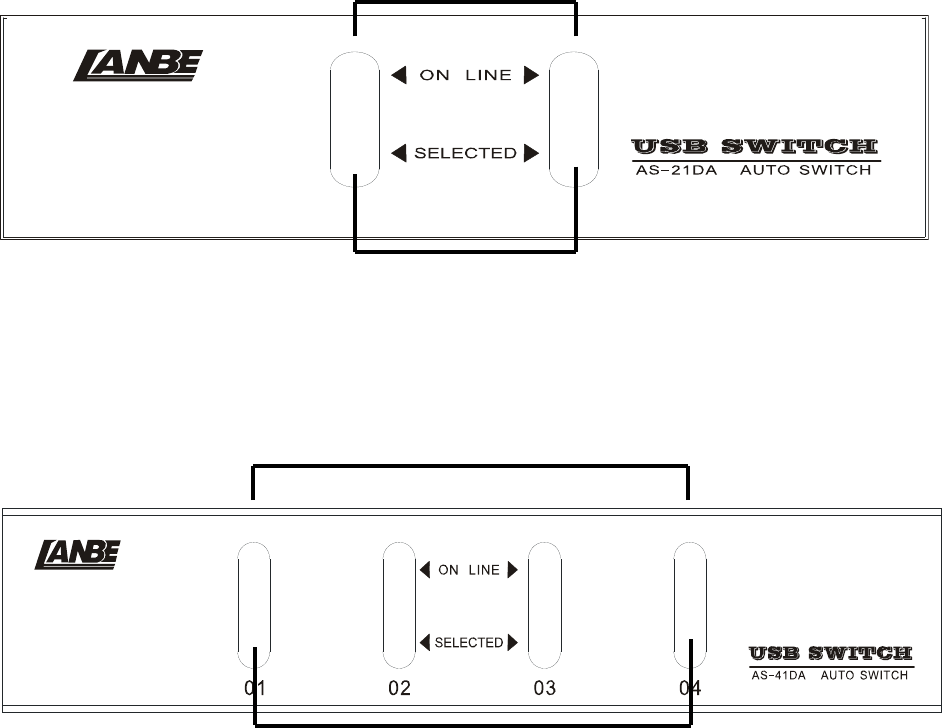
Components
Front View
AS-21DA
1
2
AS-41DA
1
2
14
Rear View
AS-21DA
34 5
67
AS-41DA
645
37
15
No. Component Description
1PortSelection
Pushbuttons
Pressing a Port Selection Pushbutton brings
the focus to the computer attached to its
corresponding port.
2 Port LEDs The Port LEDs are built into the Port
Selection
Pushbuttons.
Online – Lights green to indicate that the
computer attached to its corresponding port
is up and running.
Note: The green light for a given port is lit
for as long as there is a powered on USB
connection between the KVM switch and
computer.
Selected – Lights red to indicate that the
computer attached to its corresponding port
has the KVM.
3 Power Switch The power adapter cable plugs in here.
4 USB Console Ports Your USB keyboard and mouse plug into
these ports.
5 Audio Ports The cables from your main speakers and

16
main microphone plug in here.
6ConsoleMonitor
Port
The cable from your console monitor plugs
in here.
7KVMPort
Selection
The custom KVM cables that attach to your
computers plug in here.
17
Hardware Preparative Procedure
Before You Use
1. To prevent damage to your installation it is important that all devices are
properly grounded.
2. Make sure that the power to all devices connected to the installation are
turned off. You must unplug the power cords of any computers that have
the Keyboard Power On function.
3. A computer connected to the KVM switch should only be powered on after
all of the connections to the device are made (DVI, USB and audio).
Cable Connection
To set up your AS-21DA / AS-41DA installation, do the following:
1. Plug your USB keyboard and USB mouse into the USB console ports located
on the unit’s rear panel.
2. Plug your console monitor into the DVI console port located in the unit’s
rear panel and power on the monitor.
3. Plug your microphone and speakers into the console microphone and
speaker jacks located on the unit’s rear panel.
4. Using a KVM cable set, plug the DVI connector into any available DVI
socket in the KVM port section of the switch, then plug the accompanying
USB, microphone and speaker connectors into their corresponding USB,
18
microphone, and speaker sockets.
Note: Verify that all the plugs are in the same KVM Port sockets (all in Port
1, all in Port 2, etc.).
5. At the other end of the cable, plug the USB, video, microphone, and
speaker cables into their respective ports on the computer.
6. Plug the DC adaptor into power switch.
7. Turn on the product.
19
Operation
Powering On
When you power on your computers, the AS-21DA / AS-41DA emulates both a
mouse and keyboard on each port and allows your computers to boot
normally.
When you power on the AS-21DA / AS-41DA, the default selected port at
switch power on is the lowest port with a computer connected. The selected
computer will be displayed on the console monitor.
Note: The default connection is determined by the lowest numbered DVI
connection that is powered on.
Manual Switching
The AS-21DA / AS-41DA offers manual port-switching.Thisisachievedby
pressing the port selection pushbuttons located on the unit’s front panel.
Press and release a port selection pushbutton to bring the KVM focus to the
computer attached to its corresponding port.
The Selected LED lights red to indicate that the computer attached to its
corresponding port has the KVM.
LED Display
The AS-21DA / AS-41DA has port LEDs (Online and Selected) that are built into
20
the port selection pushbuttons to indicate port operating status, as shownin
the table below:
LED Indication
Online Lights green to indicate that the computer attached to its
corresponding port is up and running.
Note:Thegreenlightforagivenportislitforaslongas
there is a powered on USB connection between the KVM
switch and computer.
Selected Lights red to indicate that the computer attached to
its corresponding port has the KVM.
21
Appendix
Safety Instructions
Read all of these instructions. Save them for future reference.
Follow all warnings and instructions marked on the device.
Do not place the device on any unstable surface (cart, stand, table, etc.). If
the device falls, serious damage will result.
Do not use the device near water.
Donotplacethedevicenear,orover, radiators or heat registers.
The device cabinet is provided with slots and openings to allow for
adequate ventilation. To ensure reliable operation, and to protect against
overheating, these openings must never be blocked or covered.
The device should never be placed on a soft surface (bed, sofa, rug, etc.) as
this will block its ventilation openings. Likewise, the device should not be
placed in a built in enclosure unless adequate ventilation has been
provided.
Never spill liquid of any kind on the device.
Unplug the device from the wall outlet before cleaning. Do not use liquid or
aerosol cleaners. Use a damp cloth for cleaning.
The device should be operated from the type of power source indicated on
the marking label. If you are not sure of the type of power available, consult
your dealer or local power company.
The device is designed for power distribution systems with 220V voltage.
22
To prevent damage to your installation it is important that all devices are
properly grounded.
Never push objects of any kind into or through cabinet slots. They may
touch dangerous voltage points or short out parts resulting in a risk of fire
or electrical shock.
Do not attempt to service the device yourself. Refer all servicing to qualified
service personnel.
If the following conditions occur, unplug the device from the wall outlet
and bring it to qualified service personnel for repair.
The power cord or plug has become damaged or frayed.
Liquid has been spilled into the device.
The device has been exposed to rain or water.
The device has been dropped, or the cabinet has been damaged.
The device exhibits a distinct change in performance, indicating a need
for service.
The device does not operate normally when the operating instructions
are followed.

23
Specifications
Function AS-21DA AS-41DA
Computer Connections 2 4
Port Selection Pushbutton
Connector
s
Console Keyboard 1 x USB Type-A F (Black)
Video 1 x DVI-I Dual Link F (White)
Mouse 1 x USB Type-A F (Black)
Audi
o
Speaker 2 x Mini Stereo Jack F (Green)
Micropho
ne
2 x Mini Stereo Jack F (Pink)
Comput
er
Keyboard/Mouse 2 x USB Type-B F
(White)
2xUSBType-BF
(White)
Video 2 x DVI-I Dual
Link F(White)
2xDVI-IDual
Link F(White)
Audi
o
Speaker 2 x Mini Stereo
Jack F(Green)
2 x Mini Stereo
Jack F(Green)
Micropho
ne
2 x Mini Stereo
Jack F(Pink)
2 x Mini Stereo
Jack F(Pink)
Power 1 DC Adaptor
LEDs Online 2 (Green) 4 (Green)
Selected 2 (Red) 4 (Red)

24
Switches Port Selection 2 x Pushbuttons 4 x Pushbuttons
Video DVI Dual Link: 2560x1600; DVI
Single Link: 1920x1200; DVI-A:
2048x1536
Power Consumption 5.1W 5.7W
Environme
nt
Operating Temp 0-40 ℃
Storage Temp -20-60℃
Humidity 0–80% RH
Physical
Properties
Housing Mental
weight 2.06kg 2.10kg
Dimensions(LxWxH) 132x92x43
mm
202 x 110 x 43
mm
FCC NOTE:
This device complies with Part 15 of the FCC Rules.
Operation is subject to the following two conditions: (1) this device may not cause
harmful interference, and (2) this device must accept any interference received,
including interference that may cause undesired operation.
THE MANUFACTURER IS NOT RESPONSIBLE FOR ANY RADIO OR TV
INTERFERENCE CAUSED BY UNAUTHORIZED MODIFICATIONS OR
CHANGE TO THIS EQUIPMENT. SUCH MODIFICATIONS OR CHANGE
COULD VOID THE USER’S AUTHORITY TO OPERATE THE EQUIPMENT.
This equipment has been tested and found to comply with the limits for a Class B
digital device, pursuant to part 15 of the FCC Rules. These limits are designed to
provide reasonable protection against harmful interference in a residential installation.
This equipment generates, uses and can radiate radio frequency energy and, if not
installed and used in accordance with the instructions, may cause harmful interference
to radio communications. However, there is no guarantee that interference will not
occur in a particular installation. If this equipment does cause harmful interference to
radio or television reception, which can be determined by turning the equipment off
and on, the user is encouraged to try to correct the interference by one or more of the
following measures:
-- Reorient or relocate the receiving antenna.
-- Increase the separation between the equipment and receiver.
-- Connect the equipment into an outlet on a circuit different from that to which the
receiver is connected.
-- Consult the dealer or an experienced radio/TV technician for help.