Suzhou Switek Electronics and Technology AS-7100ULS LCD KVM User Manual
Suzhou Switek Electronics & Technology Co., Ltd. LCD KVM Users Manual
UserManual.wiki
>
Suzhou Switek Electronics and Technology
>
AS 7100ULS User Manual
Users Manual
Navigation menu
Upload a User Manual
Namespaces
Wiki Guide
HTML
PDF
Info
Views
User Manual
Discussion / Help
Navigation

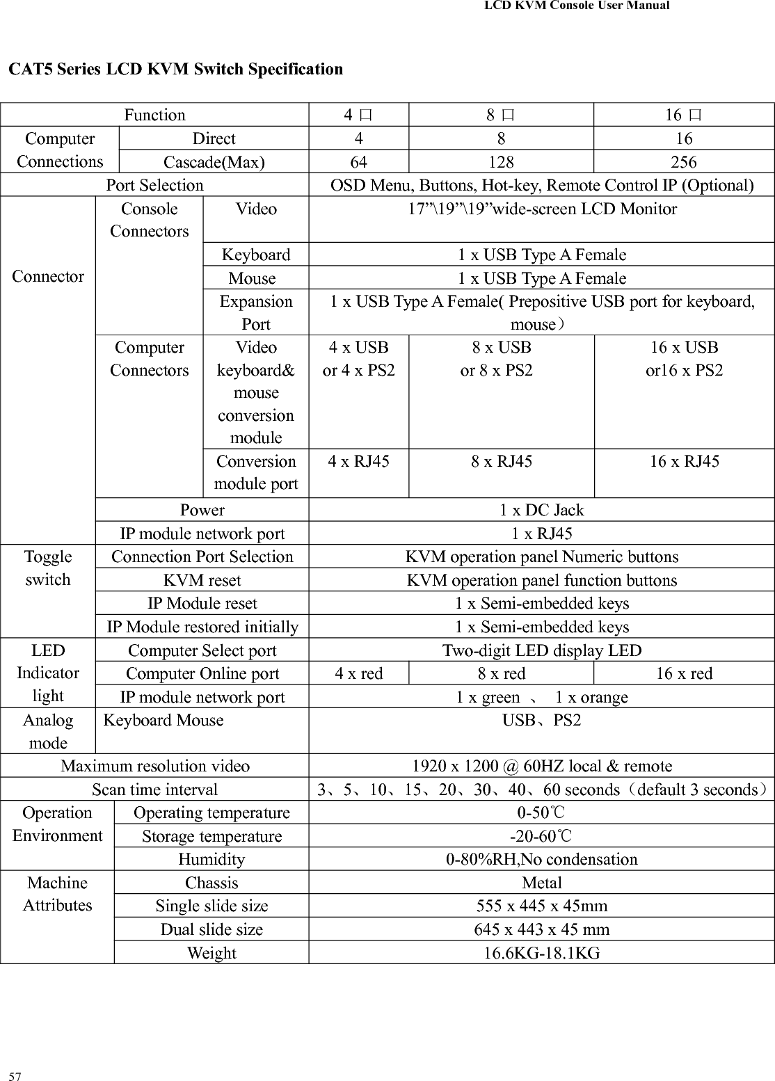
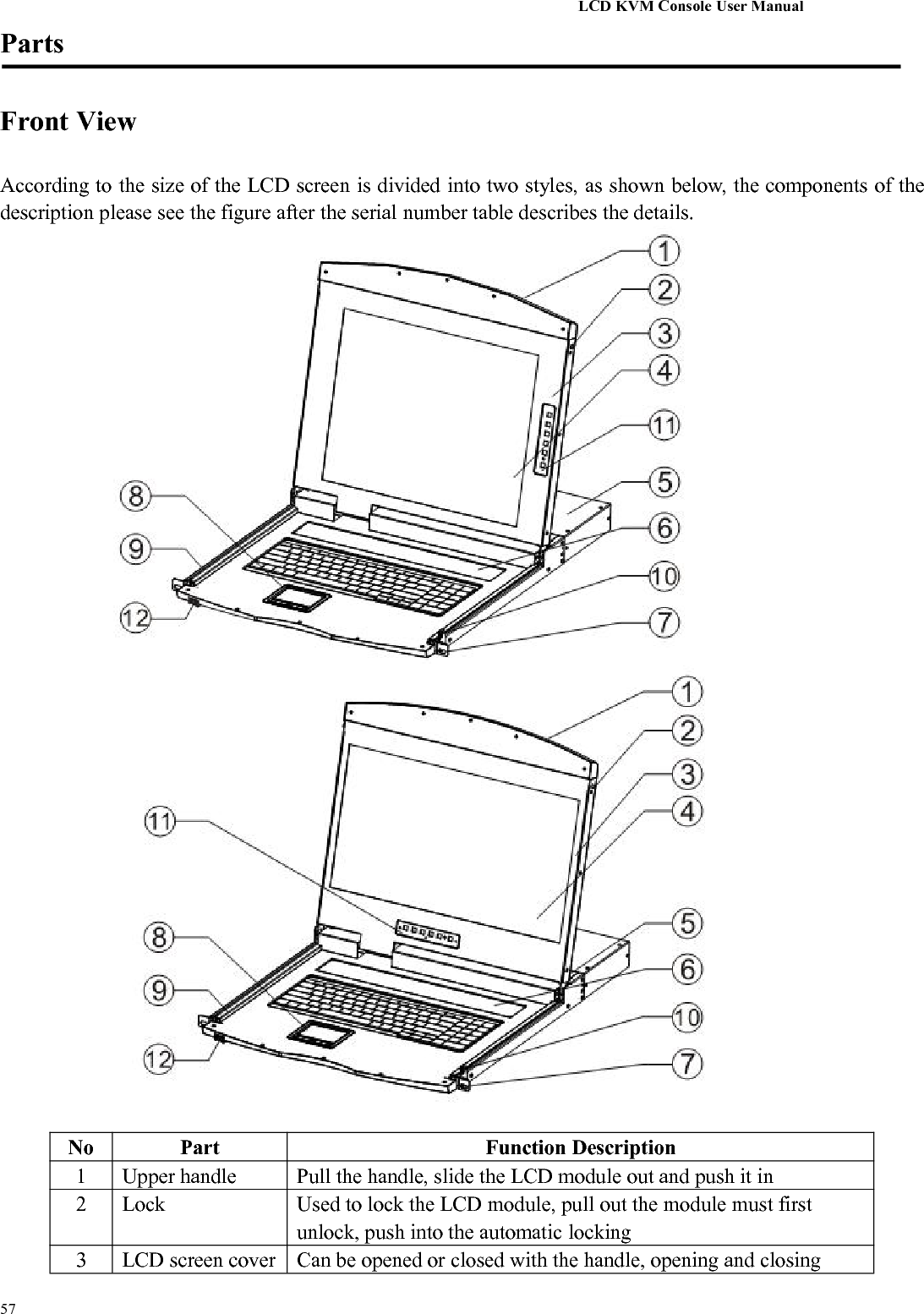
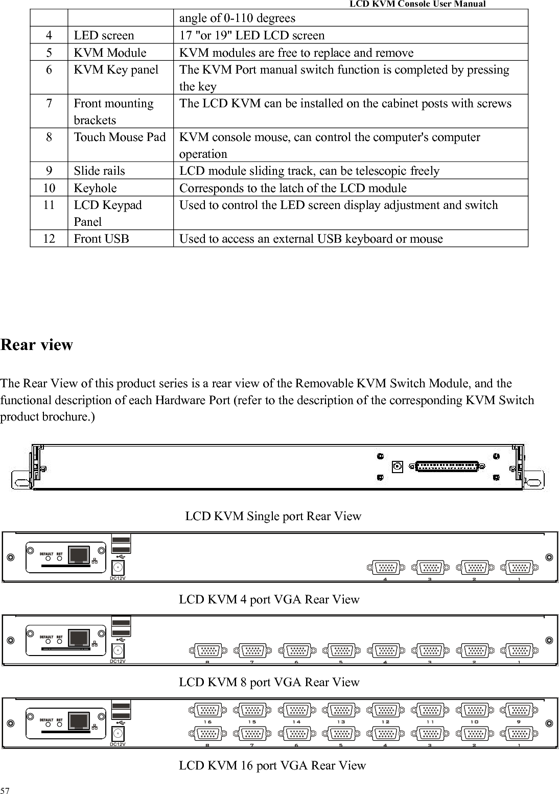
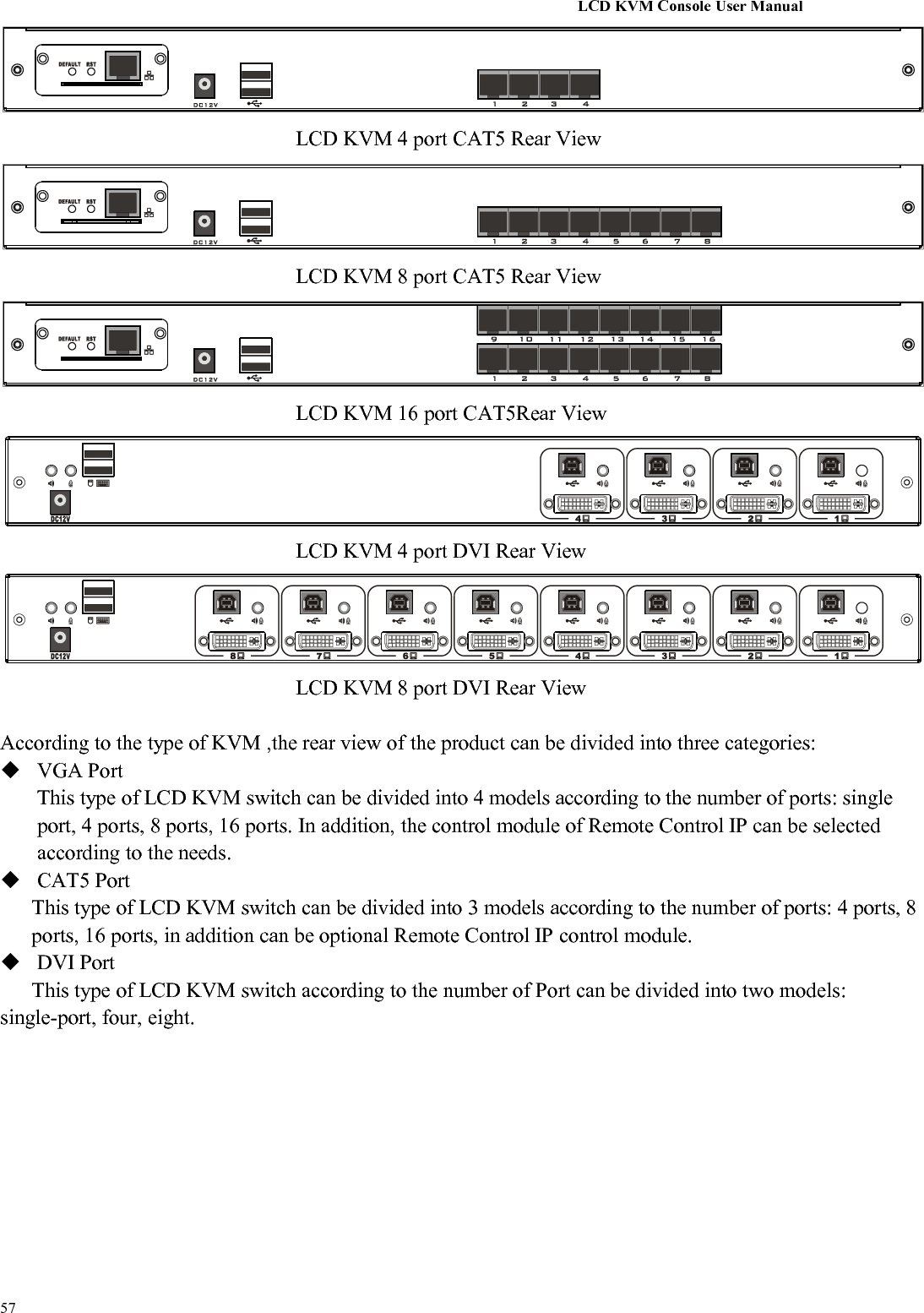
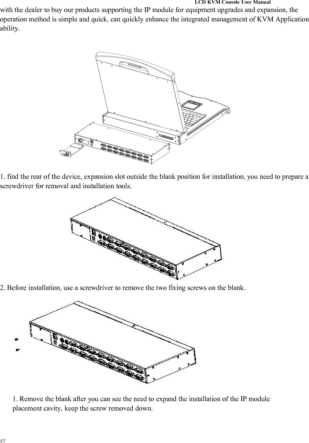
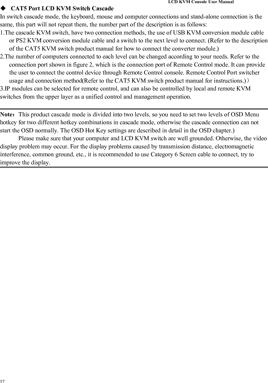
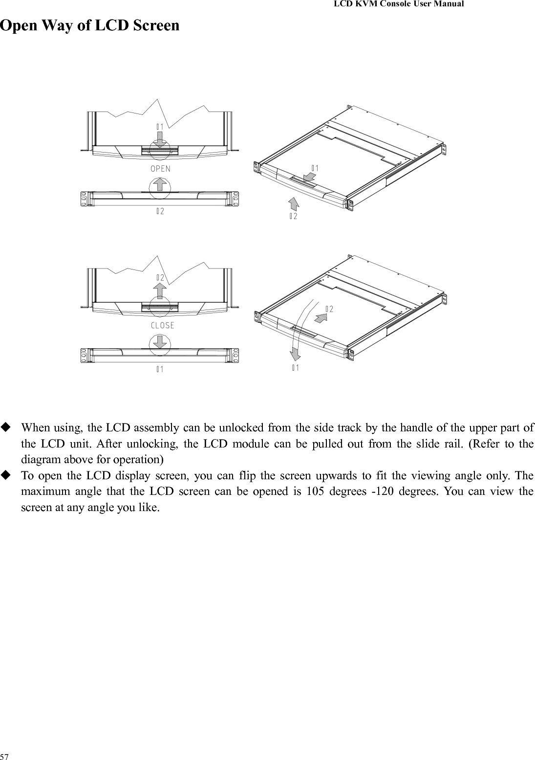
![LCD KVM Console User Manual57Description of TermsSymbol Indicates the text information that should be entered【】The parentheses indicate the keys that need to be entered. For example, [Enter] means to press theEnter key. For keys that need to be entered at the same time, they are placed in thesame bracket, and the keys are joined by a plus sign. E.g:【Ctrl+Alt】1.Numbers indicate the actual operating sequence numbers.◆The diamond symbol indicates that the information is provided forreference, but is not relevant to the procedure.The origin symbol indicates the sorting sub-item information, independent of theoperation steps.Indicates the most important information.Product InformationTo find out more about KVM's products and how to use them more efficiently, please visit our website orcontact an authorized dealer for more contact information.](https://usermanual.wiki/Suzhou-Switek-Electronics-and-Technology/AS-7100ULS/User-Guide-3395935-Page-11.png)


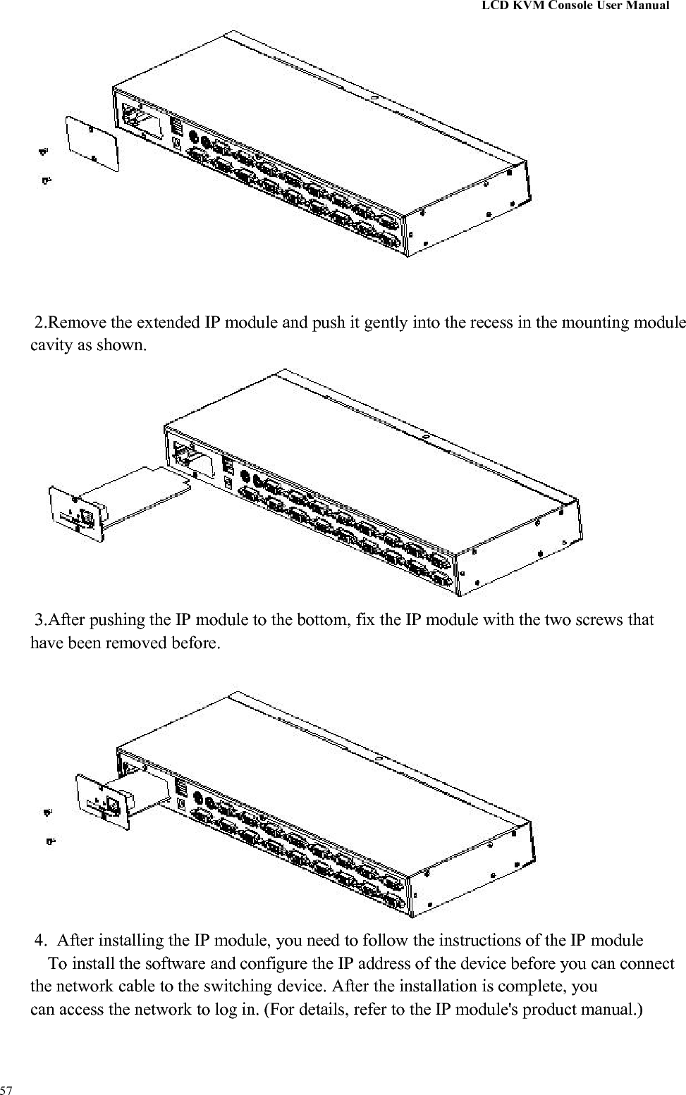
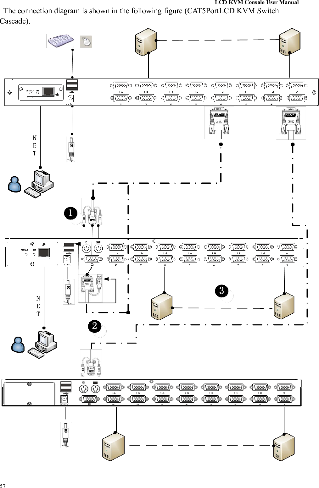
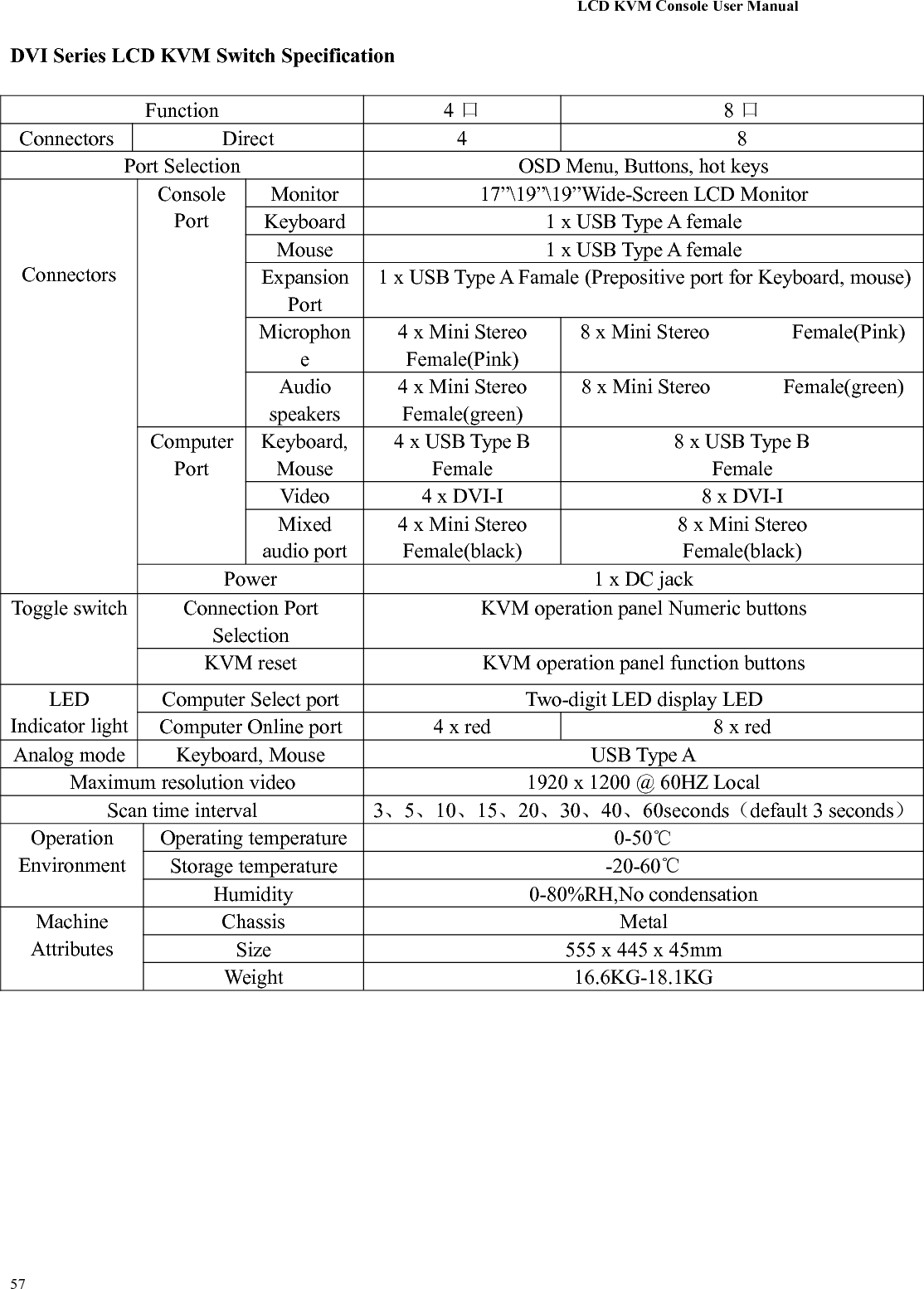
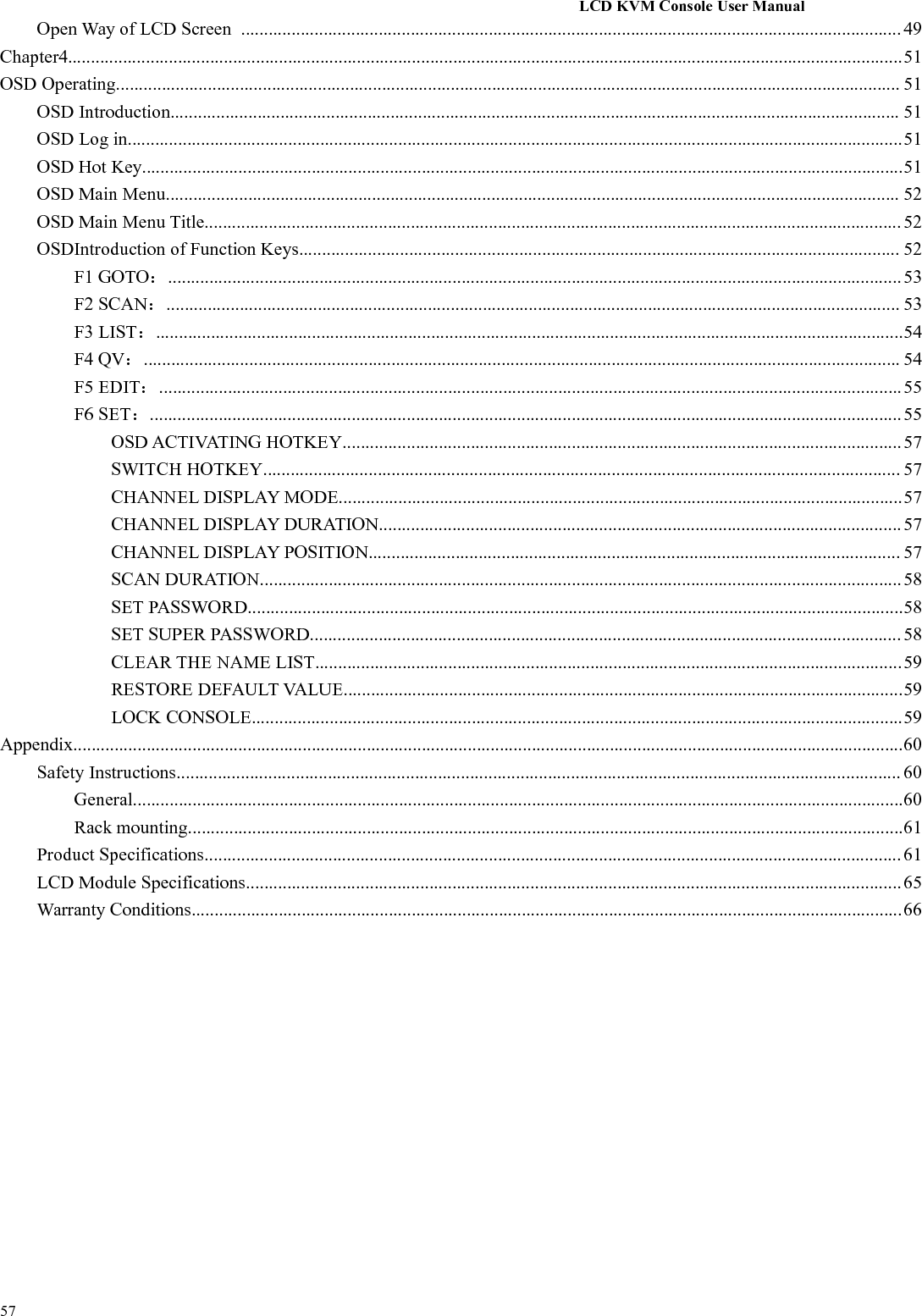
![LCD KVM Console User Manual57KVM switch button located in the top of the keyboard operating area, divided into three blocks, from left toright in order is the online indicator display area, Port switch to select the display area, Port switch digitalbutton area.Online Indicator Display AreaThe LEDs in the display area are lit when the controlled computer connected to KVM Port is connectedto the line. The LED indicating the port number is illuminated and you can see the KVM online Portstatus.Port Switch the Display AreaThe digital LED indicator in the display area shows the port serial number of the current working portwhen the working status is displayed, or the numeric key serial number you input when the key switchport changes.Port Switches the Numeric Keypad AreaThis area has the numeric keys of [0] - [9] and [RST] (reset button), [ENT] (confirm button), thenumber keys are used for Port selection, input the corresponding port number, 【ENT】to finish theswitch of Port. To reset the KVM switch, you need to click [RST] for 3-5 seconds to complete the KVMswitch restart.OSD Menu Screen SelectionLCD OSD Menu key operation【AUTO】Press the key to set the display setting for the screen to automaticallyadjust to the resolution【MENU】Press the key to perform the main function OSD Menu of the LCD screen,to select and set various functions of the screen【LEFT】Press the key to select the direction of the OSD menu, and move the currentselection to the left by one unit【RIGHT】Press the key to select the direction of the OSD menu and move the currentselection to the right by one unit【EXIT】Press to exit the OSD menu【POWER】Pressing the button allows you to turn the LCD screen on and offLED display for the LCD screen status indicator, you can indicate three working status:red, green, do not show the state. "Red" indicates that the LCD screen has been powered, but novideo signal input. "Green" indicates that the LCD normally displays the video signal of thecontrolled computer. "No display" means the LCD screen has been powered off.](https://usermanual.wiki/Suzhou-Switek-Electronics-and-Technology/AS-7100ULS/User-Guide-3395935-Page-47.png)
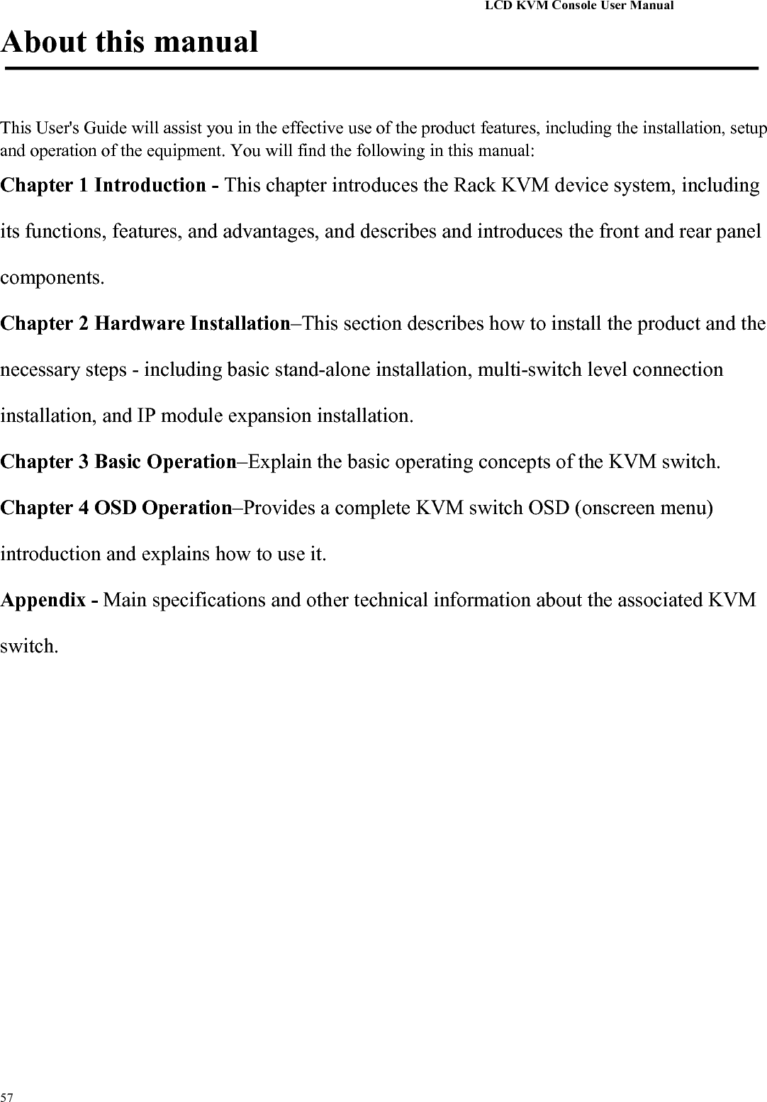
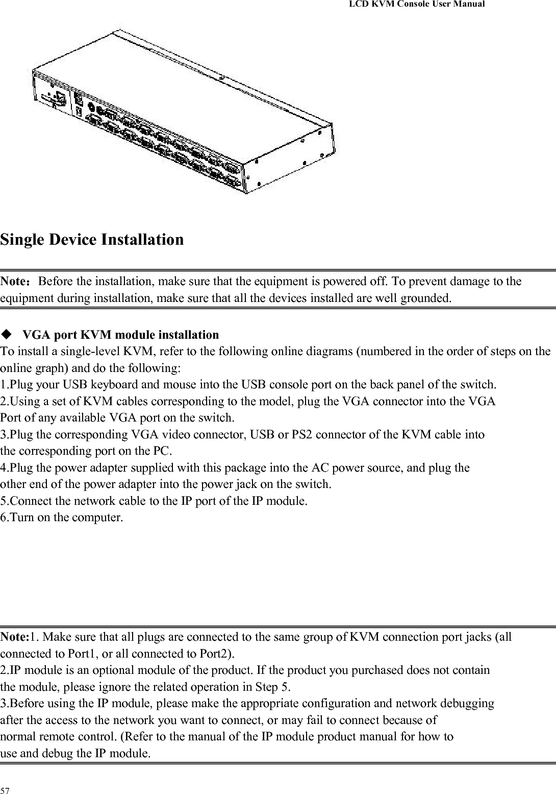
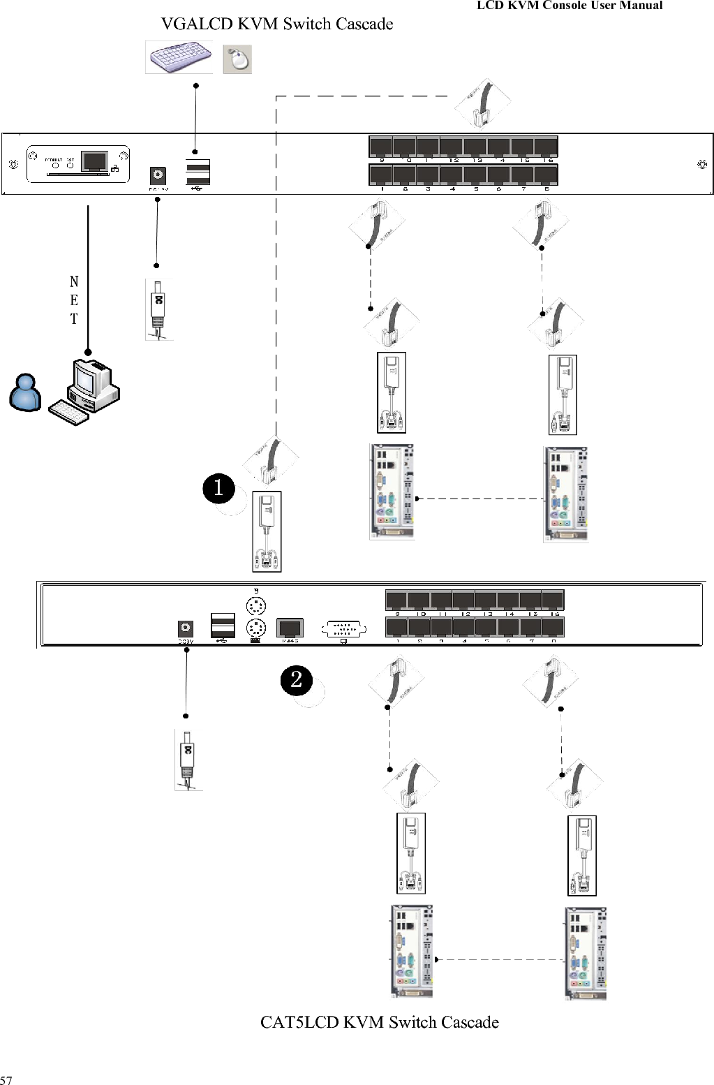
![LCD KVM Console User Manual57KVM OSD Menu operation(Refer to the OSD Operation chapter for more information.)Hotkey SelectionThis product offers four hotkey switching methods:【SCRLL】+【SCRLL】+【NUM】【CTRL】+【CTRL】+【NUM】【ALT】+【ALT】+【NUM】【SHIFT】+【SHIFT】+【NUM】The default hotkey toggle key combination is [SCRLL] + [SCRLL] + [NUM] where [NUM] is the keyboardnumber 1-16, the keyboard combination hotkey input complete carriage return completed the commandtransmission, KVM switch will switch the corresponding number Of the Port computer. If you want tochange the key combination of the hotkey, you can set and change it in the corresponding option of OSDMenu.Power Off and RestartIf you need to power off the KVM switch, do the following before turning it back on:1.Unplug the power supply to the KVM.2.Turn off all computers connected to the KVM switch.3.Wait about 10 seconds, then reconnect the KVM switch.4.Turn on the computer.Note: If the PS2 KVM cable is connected to the PC, you must connect the PS2 cable to the PC beforepowering on. Otherwise, the keyboard and mouse will not operate normally.](https://usermanual.wiki/Suzhou-Switek-Electronics-and-Technology/AS-7100ULS/User-Guide-3395935-Page-48.png)
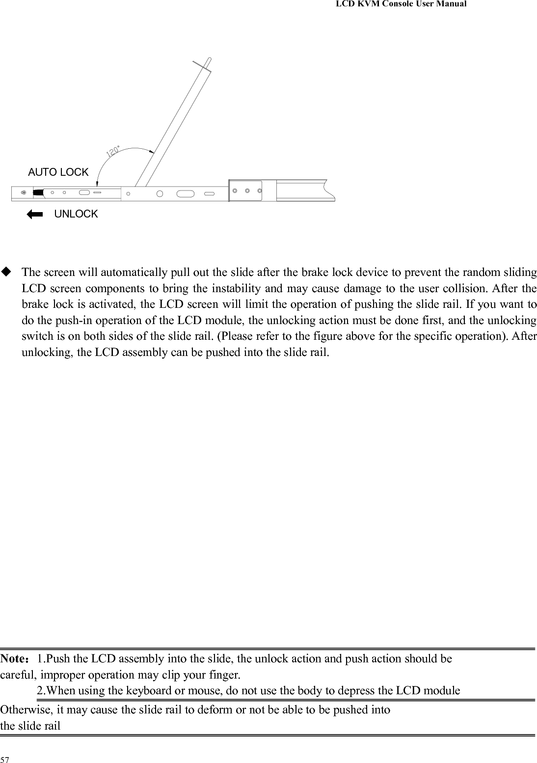
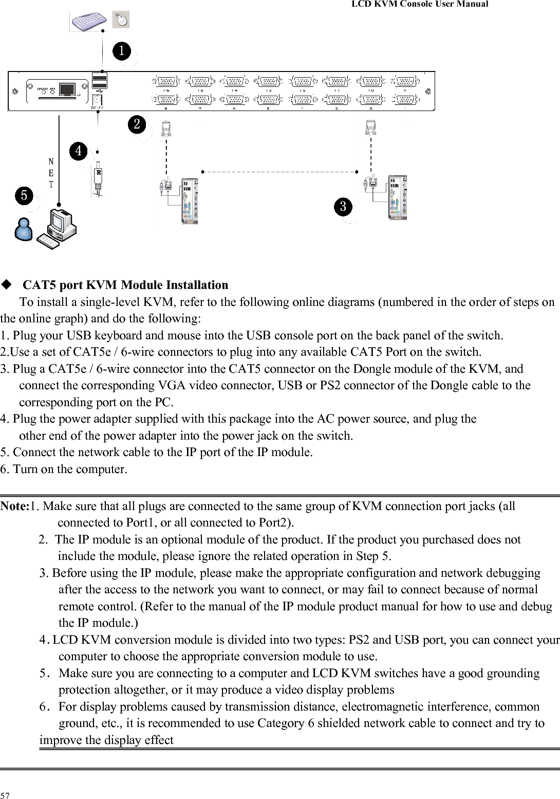
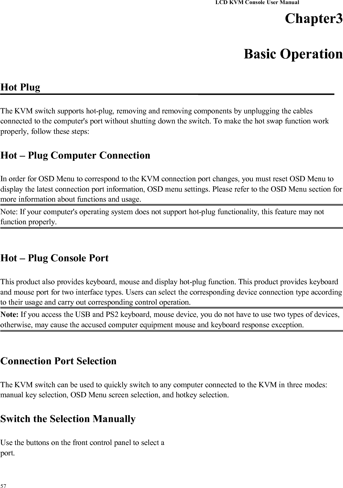
![LCD KVM Console User Manual57Chapter4OSD OperationOSD IntroductionOSD (On Screen Display), provides a menu driven interface to handle the computer switching procedure toprovide instant access to any computer on the installation.OSD Log inThe OSD function provides a two-level (administrator / user) password mechanism. The factory defaultsetting is no need to login password authentication, so you are the first time to open the OSD main menu, noneed to enter the login password to enter the OSD main menu screen for the corresponding operation. If youwant to add this function, you can enter the OSD menu, in 【F6】"SET" option to set the login password isset successfully, the subsequent login requires the correct administrator / user password to enter the OSDmenu Interface operation. When you enter the setting options, some functions may need to be edited andmodified by the administrator. The default administrator password is admin. You can also modify andchange them as needed.OSD Hot-KeyBy default, you can type the [CTRL] key twice to have the OSD menu appear on the screen of the controlleddisplay and see the connection information and status information about the connected computers on theKVM switch.Note: You can change the keyboard hotkey on the OSD menu according to your needs. This productprovides 4 sets of optional OSD menu hotkey combinations. You can select the operation according to yourneeds. (Please refer to the OSD menu for detailed description. )](https://usermanual.wiki/Suzhou-Switek-Electronics-and-Technology/AS-7100ULS/User-Guide-3395935-Page-51.png)
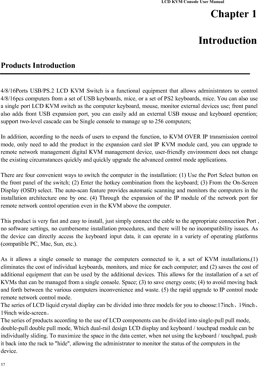
![LCD KVM Console User Manual57OSD Main MenuActive OSD, following picture will be shown on the screen:【F1】--- 【F6】at the bottom of the screen is the function setting of OSD menu, and correspondingoperation and setting of corresponding function by keyboard.After entering the OSD main screen, the port number in the center of the screen is the port number ofthe selected PC. To move up and down through the list one line at a time, use the【↑】【↓】Arrow Keys,press 【Enter】to select the switch port.Please press【Esc】to exit the OSD menu interfaceTo move up or down a row in the list, use the【↑】【↓】arrow keys. If the number of rows in the list islarger than the number that the screen can display, the screen scrolls.When the OSD menu is closed, a small blue window will appear on the screen showing the port numberthat is currently switched to.OSD Main Screen HeadingsHeadingExplanationPNThis column lists the port numbers for all the CPU ports on the installation. Thesimplest method to access a particular computer is to move the highlight bar to it,then press [Enter].QVIf a port has been selected for Quick View scanning, an arrowhead symboldisplays in this column to indicate so.PCThe computers that are powered on and are on line have an arrowhead symbol inthis column to indicate so.NAMEIf a port has been given a name, its name appears in this column.OSD FunctionOSD functions are used to configure and control the OSD. For example, you can: rapidly switch to any port;scan selected ports only; limit the list you wish to view; designate a port as a Quick View Port; create or edit](https://usermanual.wiki/Suzhou-Switek-Electronics-and-Technology/AS-7100ULS/User-Guide-3395935-Page-52.png)
![LCD KVM Console User Manual57a port name; or make OSD setting adjustments.To activate the OSD function key:1. Press any function key【F1】--- 【F6】at the bottom of main screen to input the function key.2. On the sub-menu, move the selection column to the option, and then press the {Enter} key.3. Press the【Esc】key to return to the previous menu.F1 GOTO:Press the 【F1】key to start the GOTO function. The GOTO function allows you to switch directly to theconnection port by typing the port name or its port number.1. To use “NAM” method, move highlight bar to “NAME”, press 【Enter】, input name of a port, then press[Enter] to confirm.2. To use PN method, move highlight bar to “PN”, press 【Enter】, input port number, then press 【Enter】to switch. If the port number is invalid, it will remind the user to input again.Note:1. When keying name, if there is a matching name, the matched name will appear on the screen, justpress [Enter] to switch to that port.2.In the "PN" port input box, only allow the input of numbers, such as the input of other characters areregarded as invalid input, and can hear the equipment issued by the warning tone.To return to main menu, press [Esc].F2 SCAN:The "SCAN" function allows you to perform automatic port scanning of the connected computers. Users canswitch ports in order to view the corresponding port computer status.The SCAN function can automatically scan from current selected port, the scan interval can be set byusers.When scanning, a small window on the screen indicates the current port number.](https://usermanual.wiki/Suzhou-Switek-Electronics-and-Technology/AS-7100ULS/User-Guide-3395935-Page-53.png)
![LCD KVM Console User Manual57Press [Space] to stop scanning, and the KVM switches to the port last scanned.F3 LIST:The LIST function lets you broaden or narrow the scope of which ports the OSD displays on the mainscreen.Many of the OSD functions only operate on the computers that have been selected for listing on the mainscreen with this function. The choices and their meanings are given in the table below:ChoiceMeaningALLLists all of the ports on the installation.QVIEWLists only the ports that have been selected as Quick View Ports.POWERED ONLists only the ports that have their attached computers powered on.POWERED ON +QVIEWLists only the ports that have their attached computers powered on and havebeen selected as Quick View Ports.QVIEW + NAMELists only the ports that have been selected as Quick View Ports and havename.NAMELists only the ports that have names.Move the highlight bar to the choice you want, then press [enter]. An icon appears before the choice toindicate that it is the currently selected one.After you make your choice and press [Enter], you return to the OSD main screen with the newly formulatedlist displayed.F4 QV:QV function can select port as Quick View.](https://usermanual.wiki/Suzhou-Switek-Electronics-and-Technology/AS-7100ULS/User-Guide-3395935-Page-54.png)
![LCD KVM Console User Manual57Move the highlight bar to a port, press [F4], an icon of up triangle appears. Press [F4] again, the icondisappears.F5 EDIT:EDIT function creates or edits the name of a port. Press [F5], a pink edit box will appear on the screen. Inputname, and then press [Enter], the port is set a name and it will also appear on the screen.F6 SET:SET function settings can be set to the administrator and the user to set the OSD menu. The related functionsand user rights related settings, such as management settings login password, display mode, switch hotkeyadjustment and so on.](https://usermanual.wiki/Suzhou-Switek-Electronics-and-Technology/AS-7100ULS/User-Guide-3395935-Page-55.png)
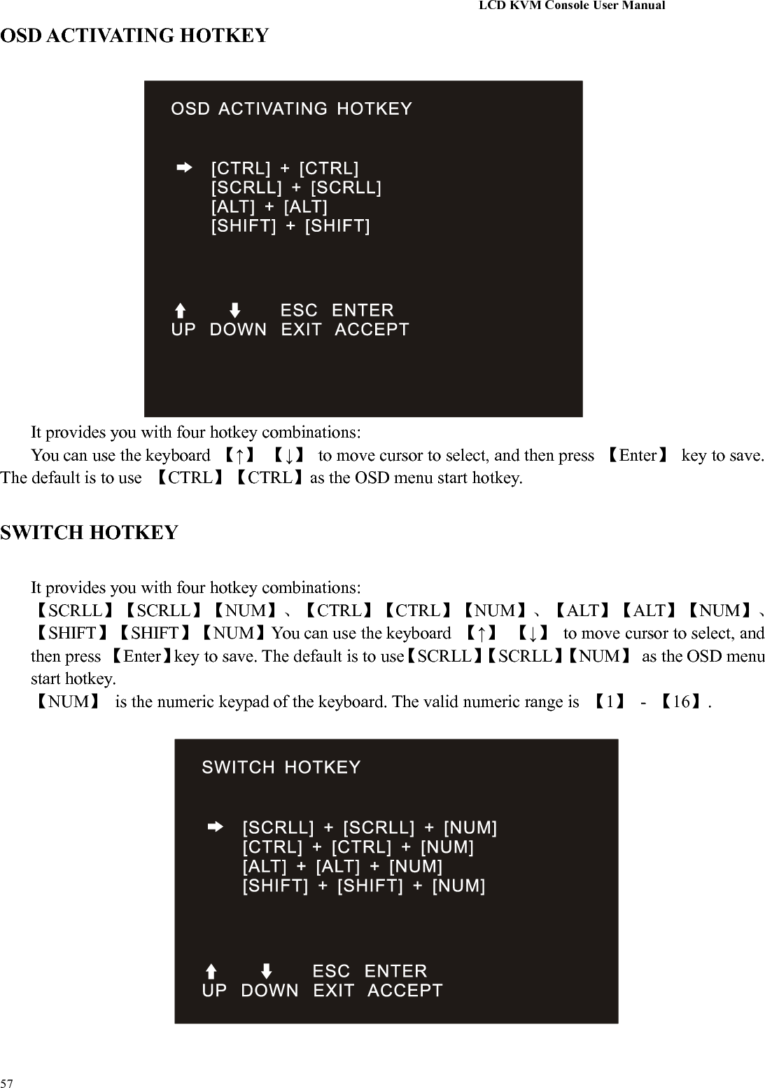
![LCD KVM Console User Manual57To change your settings:1. Move the selection column to this option, press 【Enter】to enter a setting option.2.After selecting an item, the sub-menu and the further options provided will appear. To select it,double-click the mouse or move the selection column to the option, and then press the [Enter] key, an iconwill appear. Select the option before to indicate that the item has been selected. The settings are described inthe following table:SettingsFunctionOSD ACTIVATING HOTKEYOSD Menu Activates hotkey combination selectionsettingsSWITCH HOTKEYKVM port switch hot-key combination selectionsettingSCAN DURATIONPort scan dwell time settingSET PASSWORDUser login password settingsSET SUPER PASSWORDThe administrator login password settingsCLEAR THE NAME LISTClear the port name settingRESTORE DEFAULT VALUEResetLOCK CONSOLEOSD Menu Password Login Function settings](https://usermanual.wiki/Suzhou-Switek-Electronics-and-Technology/AS-7100ULS/User-Guide-3395935-Page-56.png)
![LCD KVM Console User Manual57SCAN DURATIONDuration for scanning one port.Options are 3 seconds, 5 seconds, 10 seconds, 15 seconds, 20 seconds, 30 seconds, 40 seconds, 60seconds. Move the highlight bar to an option and press [Enter] to select it.SET PASSWORDSet new password.First enter old password, then enter new password and confirm it. The new password is set. If erroroccurs, the screen will remind users.SET SUPER PASSWORDWhen setting the administrator password, you need to enter the correct password. Before new passwordis updated, input the previous password twice, the new password to take effect](https://usermanual.wiki/Suzhou-Switek-Electronics-and-Technology/AS-7100ULS/User-Guide-3395935-Page-58.png)