Suzhou Switek Electronics and Technology AS-7100ULS LCD KVM User Manual
Suzhou Switek Electronics & Technology Co., Ltd. LCD KVM Users Manual
Users Manual
LCD KVM SWITCH
User Manual
LCD KVM Console User Manual
57
Statement
United States Federal Communications Commission Interference Statement
This product has been tested and found to comply with FCC regulations Class B (Class B) digital device and
FCC specifications Details of Section 15.These specifications are intended to be used in a commercial
environment without harmful interference and to provide for the protection of regulated equipment. This
equipment generates, and can radiate radio, so if you do not have to install and use as specified in this manual,
may cause interference to radio communications. However, there is no guarantee that interference will not
occur in a particular installation. If the equipment is turned on or off causing interference to radio and television
reception, the user should try the following to reduce the interference.
Change the direction and move the receiving antenna.
Increase the distance between the equipment and the receiver.
Connect the device to the circuit outlet (not the interface to which the receiver is connected)。
Consult the dealer and an experienced radio / TV technician for help.
FCC Warning: change and modify non-qualified party which is responsible for the equipment is made to void
the user's authority to operate the equipment.
CE WARNING: This product is a Class B product. In a domestic environment, this product may cause radio
interference, and the user may need to take appropriate precautions.
RoHS
This product is RoHS compliant.
The users manual or instruction manual for an intentional or unintentional radiator shall caution the user that changes
or modifications not expressly approved by the party responsible for compliance could void the user's authority to
operate the equipment.
In cases where the manual is provided only in a form other than paper, such as on a computer disk or over the
Internet, the information required by this section may be included in the manual in that alternative form, provided the
user can reasonably
be expected to have the capability to access information in that form.
This device complies with Part 15 of the FCC Rules. Operation is
subject to the following two conditions: (1) this device may not cause
harmful interference, and (2) this device must accept any interference
received, including interference that may cause undesired operation.
LCD KVM Console User Manual
57
User Precautions
The manufacturer has the right to modify and alter the information, documentation and specifications contained
in this manual without prior notice. Manufactures makes no warranty, express, implied or statutory, disclaims
or specifically disclaims it's possibility of sale and applicability for a particular purpose. The same applies to
any sold and authorized manufacturer's software described in this manual. If the Software Program is found to
be defective after purchase, the purchaser (and any non-manufacturer, its distributor or its purchaser) will be
responsible for all necessary service, repair and any incidental or consequential damages resulting from the
Software defect. The manufacturer is not responsible for any unauthorized interference with the radio or
television caused by this equipment. The user must correct the interference personally. The manufacturer will
not be liable for any damage resulting from incorrect selection of the operating voltage before operation.
Please be sure that the voltage has been set correctly before use.
A typical LCD (liquid crystal display) has millions of pixels. A dead pixel is a defective pixel that does not
display the correct color. On the screen, it usually looks like a tiny black or white dot, which can also be any
other color. In the manufacturing process, even if a pixel on the tiny dust particles, or in the course of a slight
impact during transport, may have a dead pixel. In the ISO 13406-2 specification, four categories of acceptable
screen dead pixels are defined: the first is the best product, and the fourth is the worst. Almost all manufacturers
use the second level as a guarantee of the product, allowing a certain number of dead pixels exist, such as more
than the tolerance will change the screen. Since the manufacturer is of the opinion that this screen is permitted
by the ISO specification, we are not responsible for the replacement or warranty of the TFT LCD panel.

LCD KVM Console User Manual
57
Product Model Description
Single-rail Series
Configuration instructions
AS-7100ULS
VGA Single portKVM,17inch 4:3 LED Monitor, No OSD Menu, Can be cascaded
AS-7100DLS
DVI Single port KVM,17inch4:3 LCD Monitor, No OSD Menu
AI-7100ULS
VGA Single portKVM,17inch4:3 LCD Monitor, No OSD Menu, Can be cascaded, IP Remote Control
AS-9100ULS
VGA Single portKVM,19inch4:3 LCD Monitor, No OSD Menu, Can be cascaded
AS-9100DLS
DVI Single portKVM,19inch4:3 LCD Monitor, No OSD Menu
AI-9100ULS
VGA Single portKVM,19inch4:3 LCD Monitor, No OSD Menu, Can be cascaded, IP Remote Control
AS-7104ULS
VGA 4Ports KVM ,17inch4:3 LCD Monitor, OSD Menu, Demountable Structure, Can be cascaded
AS-7104TLS
CAT5 4Ports KVM ,17inch4:3 LCD Monitor, OSD Menu, Demountable Structure, Can be cascaded
AS-7104DLS
DVI 4Ports KVM ,17inch4:3 LCD Monitor, OSD Menu, Demountable Structure
AI-7104ULS
VGA 4Ports KVM ,17inch4:3 LCD Monitor, OSD Menu, Demountable Structure, Can be cascaded, IP
Remote Control
AI-7104TLS
CAT5 4Ports KVM ,17inch4:3 LCD Monitor, OSD Menu, Demountable Structure, Can be cascaded, IP
Remote Control
AS-9104ULS
VGA 4Ports KVM ,19inch4:3 LCD Monitor, OSD Menu, Demountable Structure, Can be cascaded
AS-9104TLS
CAT5 4Ports KVM ,19inch4:3 LCD Monitor, OSD Menu, Demountable Structure, Can be cascaded
AS-9104DLS
DVI 4Ports KVM ,19inch4:3 LCD Monitor, OSD Menu, Demountable Structure
AI-9104ULS
VGA 4Ports KVM ,19inch4:3 LCD Monitor, OSD Menu, Demountable Structure, Can be cascaded, IP
Remote Control
AS-7108ULS
VGA 8Ports KVM ,17inch4:3 LCD Monitor, OSD Menu, Demountable Structure, Can be cascaded
AS-7108TLS
CAT5 8Ports KVM,17inch4:3 LCD Monitor, OSD Menu, Demountable Structure, Can be cascaded
AS-7108DLS
DVI 8Ports KVM,17inch4:3 LCD Monitor, OSD Menu, Demountable Structure,
AI-7108ULS
VGA 8Ports KVM,17inch4:3 LCD Monitor, OSD Menu, Demountable Structure, Can be cascaded, IP
Remote Control
AI-7108TLS
CAT5 8Ports KVM,17inch4:3 LCD Monitor, OSD Menu, Demountable Structure, Can be cascaded, IP
Remote Control
AS-9108ULS
VGA 8Ports KVM,19inch4:3 LCD Monitor, OSD Menu, Demountable Structure, Can be cascaded
AS-9108TLS
CAT5 8Ports KVM,19inch4:3 LCD Monitor, OSD Menu, Demountable Structure, Can be cascaded
AS-9108DLS
DVI 8Ports KVM,19inch4:3 LCD Monitor, OSD Menu, Demountable Structure,
AI-9108ULS
VGA 8Ports KVM,19inch4:3 LCD Monitor, OSD Menu, Demountable Structure, Can be cascaded, IP
Remote Control
AI-9108TLS
CAT5 8Ports KVM,19inch4:3 LCD Monitor, OSD Menu, Demountable Structure, Can be cascaded, IP
Remote Control
AS-7116ULS
VGA 16Ports KVM,17inch4:3 LCD Monitor, OSD Menu, Demountable Structure, Can be cascaded
AS-7116TLS
CAT5 16Ports KVM,17inch4:3 LCD Monitor, OSD Menu, Demountable Structure, Can be cascaded
AI-7116ULS
VGA 16Ports KVM,17inch4:3 LCD Monitor, OSD Menu, Demountable Structure, Can be cascaded, IP
Remote Control
AI-7116TLS
CAT5 16Ports KVM,17inch4:3 LCD Monitor, OSD Menu, Demountable Structure, Can be cascaded,

LCD KVM Console User Manual
57
Remote Control
AS-9116ULS
VGA 16Ports KVM,19inch4:3 LCD Monitor, OSD Menu, Demountable Structure, Can be cascaded
AS-9116TLS
CAT5 16Ports KVM,19inch4:3 LCD Monitor, OSD Menu, Demountable Structure, Can be cascaded
AI-9116ULS
VGA 16Ports KVM,19inch4:3 LCD Monitor, SD Menu, Demountable Structure, Can be cascaded, IP
Remote Control
AI-9116TLS
CAT5 16Ports KVM,19inch4:3 LCD Monitor, OSD Menu, Demountable Structure, Can be cascaded, IP
Remote Control
Dual-rail Series
Model
Configuration instructions
AS-7100ULD
VGA Single port VM ,17inch4:3 LCD Monitor, No OSD menu, Demountable Structure, Can be cascaded
AI-7100ULD
VGA ingle port KVM ,17inch4:3 LCD Monitor, No OSD menu, Demountable Structure, Can be
cascaded, IP Remote Control
AS-9100ULD
VGA Single port KVM ,19inch4:3 LCD Monitor, No OSD menu, Demountable Structure, Can be
cascaded
AI-9100ULD
VGA Single port KVM ,19inch4:3 LCD Monitor, No OSD menu, Demountable Structure, Can be
cascaded, IP Remote Control
AS-7104ULD
VGA 4Ports KVM,17inch4:3 LCD Monitor, OSD Menu, Demountable Structure, Can be cascaded
AS-7104TLD
CAT5 4Ports KVM,17inch4:3 LCD Monitor, OSD Menu, Demountable Structure, Can be cascaded
AI-7104ULD
VGA 4Ports KVM,17inch4:3 LCD Monitor, OSD Menu, Demountable Structure, Can be cascaded, IP
Remote Control
AI-7104TLD
CAT54Ports KVM,17inch4:3 LCD Monitor, OSD Menu, Demountable Structure, Can be cascaded, IP
Remote Control
AS-9104ULD
VGA 4Ports KVM,19inch4:3 LCD Monitor, OSD Menu, Demountable Structure, Can be cascaded
AS-9104TLD
CAT5 4Ports KVM,19inch4:3 LCD Monitor, OSD Menu, Demountable Structure, Can be cascaded
AI-9104ULD
VGA 4Ports KVM,19inch4:3 LCD Monitor, OSD Menu, Demountable Structure, Can be cascaded, IP
Remote Control
AI-9104TLD
CAT5 4Ports KVM,19inch4:3 LCD Monitor, OSD Menu, Demountable Structure, Can be cascaded, IP
Remote Control
AS-7108ULD
VGA 8Ports KVM,17inch4:3 LCD Monitor, OSD Menu, Demountable Structure, Can be cascaded
AS-7108TLD
CAT5 8Ports KVM,17inch4:3 LCD Monitor, OSD Menu, Demountable Structure, Can be cascaded
AI-7108ULD
VGA 8Ports KVM,17inch4:3 LCD Monitor, OSD Menu, Demountable Structure, Can be cascaded, IP
Remote Control
AI-7108TLD
CAT5 8Ports KVM,17inch4:3 LCD Monitor, OSD Menu, Demountable Structure, Can be cascaded, IP
Remote Control
AS-9108ULD
VGA 8Ports KVM,19inch4:3 LCD Monitor, OSD Menu, Demountable Structure, Can be cascaded
AS-9108TLD
CAT5 8Ports KVM,19inch4:3 LCD Monitor, OSD Menu, Demountable Structure, Can be cascaded
AI-9108ULD
VGA 8Ports KVM,19inch4:3 LCD Monitor, OSD Menu, Demountable Structure, Can be cascaded, IP
Remote Control
AI-9108TLD
CAT5 8Ports KVM,19inch4:3 LCD Monitor ,OSD Menu, Demountable Structure, Can be cascaded, IP
Remote Control
AS-7116ULD
VGA 16Ports KVM,17inch4:3 LCD Monitor, OSD Menu, Demountable Structure, Can be cascaded

LCD KVM Console User Manual
57
AS-7116TLD
CAT5 16Ports KVM,17inch4:3 LCD Monitor, OSD Menu, Demountable Structure, Can be cascaded
AI-7116ULD
VGA 16Ports KVM,17inch4:3 LCD Monitor, OSD Menu, Demountable Structure, Can be cascaded, IP
Remote Control
AI-7116TLD
CAT5 16Ports KVM,17inch4:3 LCD Monitor, OSD Menu, Demountable Structure, Can be cascaded, IP
Remote Control
AS-9116ULD
VGA 16Ports KVM,19inch4:3 LCD Monitor, OSD Menu, Demountable Structure, Can be cascaded
AS-9116TLD
CAT5 16Ports KVM,19inch4:3 LCD Monitor, OSD Menu, Demountable Structure, Can be cascaded
AI-9116ULD
VGA 16Ports KVM,19inch4:3 LCD Monitor, OSD Menu, Demountable Structure, Can be cascaded, IP
Remote Control
AI-9116TLD
CAT5 16Ports KVM,19inch4:3 LCD Monitor, OSD Menu, Demountable Structure, Can be cascaded, IP
Remote Control
LCD KVM Console User Manual
57
Package Contents
The LCD KVM switch package includes the following:
Name
Quantity/unit
Description
LCD KVM Console
1/pc
The LCD kit products
KVM Cables
N/pc
Cables quantities according to the standard
Port that selected
Power
1/pc
If it is built-in power supply products, power
built-in.
Power Cord
1/pc
Standard 1.8 m power cord
Instructions(CD)
1/pc
Using electronic data CD manual
Quick Installation Guide
1/pc
Quick installation manual
Mounting brackets
2/pcs
LCD KMV Single mounting bracket
Lock ear
2/pcs
LCD KVM fix the rear panel
Install the screw kit
1/pc
Screw the mounting bracket
Check that all parts are present and that they are not damaged in transit. If you encounter problems, contact
your dealer.
To prevent damage to the machine or equipment connected to the machine, please read this manual carefully
and follow the instructions to install and operate it.
* There may be additional product features since the publication of this manual. Please visit our website to
download the latest version of the user's manual.

LCD KVM Console User Manual
57
Contents
User Precautions........................................................................................................................................................................... 3
Product Model Description...........................................................................................................................................................4
Single Slide Series................................................................................................................................................................ 4
Dual-rail Series..................................................................................................................................................................... 5
Package Contents..........................................................................................................................................................................7
About this manual.......................................................................................................................................................................10
Description of Terms.................................................................................................................................................................. 11
Chapter 1.....................................................................................................................................................................................12
Introduction.................................................................................................................................................................................12
Production Introduction......................................................................................................................................................12
Product Features................................................................................................................................................................. 14
Hardware Requirements..................................................................................................................................................... 15
Console....................................................................................................................................................................... 15
Computer.................................................................................................................................................................... 15
Cables......................................................................................................................................................................... 15
Operation System....................................................................................................................................................... 18
Part......................................................................................................................................................................................19
Front View..................................................................................................................................................................19
Rear View................................................................................................................................................................... 20
Front view of the 4: 3 screen and 16: 9 screen .........................................................................................................22
Single Slide & Dual Slide LCD Display....................................................................................................................23
Overall Dimensions of the LCD KVM .................................................................................................................... 25
Chapter 2.....................................................................................................................................................................................27
Hardware Installation................................................................................................................................................................. 28
Stacking and Installation Precautions................................................................................................................................ 28
Standard Rack Mounting............................................................................................................................................28
KVM Modules’ Assembly & Removal......................................................................................................................31
Removal of the Keyboard Module............................................................................................................................. 33
Expansion Module Installation...................................................................................................................................34
Single Device Installation.......................................................................................................................................... 37
Installation of Single Port LCD KVM Switch........................................................................................................... 40
Cascade Device Connection.......................................................................................................................................42
Chapter3......................................................................................................................................................................................46
Basic Operation.......................................................................................................................................................................... 46
Hot Plug.............................................................................................................................................................................. 46
Hot - Plug Computer Connection...............................................................................................................................46
Hot - Plug Console Port..............................................................................................................................................46
Connection Port Selection.................................................................................................................................................. 46
Switch the Selection Manually...................................................................................................................................46
OSD Menu Screen Selection......................................................................................................................................47
Hotkey Selection........................................................................................................................................................ 48
Power Off and Restart........................................................................................................................................................ 48
LCD KVM Console User Manual
57
Open Way of LCD Screen ................................................................................................................................................ 49
Chapter4......................................................................................................................................................................................51
OSD Operating........................................................................................................................................................................... 51
OSD Introduction............................................................................................................................................................... 51
OSD Log in.........................................................................................................................................................................51
OSD Hot Key......................................................................................................................................................................51
OSD Main Menu................................................................................................................................................................ 52
OSD Main Menu Title........................................................................................................................................................ 52
OSDIntroduction of Function Keys................................................................................................................................... 52
F1 GOTO:................................................................................................................................................................53
F2 SCAN:................................................................................................................................................................ 53
F3 LIST:...................................................................................................................................................................54
F4 QV:..................................................................................................................................................................... 54
F5 EDIT:..................................................................................................................................................................55
F6 SET:....................................................................................................................................................................55
OSD ACTIVATING HOTKEY..........................................................................................................................57
SWITCH HOTKEY........................................................................................................................................... 57
CHANNEL DISPLAY MODE...........................................................................................................................57
CHANNEL DISPLAY DURATION..................................................................................................................57
CHANNEL DISPLAY POSITION.................................................................................................................... 57
SCAN DURATION............................................................................................................................................58
SET PASSWORD...............................................................................................................................................58
SET SUPER PASSWORD................................................................................................................................. 58
CLEAR THE NAME LIST................................................................................................................................59
RESTORE DEFAULT VALUE..........................................................................................................................59
LOCK CONSOLE..............................................................................................................................................59
Appendix.....................................................................................................................................................................................60
Safety Instructions.............................................................................................................................................................. 60
General........................................................................................................................................................................60
Rack mounting............................................................................................................................................................61
Product Specifications........................................................................................................................................................ 61
LCD Module Specifications...............................................................................................................................................65
Warranty Conditions...........................................................................................................................................................66

LCD KVM Console User Manual
57
About this manual
This User's Guide will assist you in the effective use of the product features, including the installation, setup
and operation of the equipment. You will find the following in this manual:
Chapter 1 Introduction - This chapter introduces the Rack KVM device system, including
its functions, features, and advantages, and describes and introduces the front and rear panel
components.
Chapter 2 Hardware Installation–This section describes how to install the product and the
necessary steps - including basic stand-alone installation, multi-switch level connection
installation, and IP module expansion installation.
Chapter 3 Basic Operation–Explain the basic operating concepts of the KVM switch.
Chapter 4 OSD Operation–Provides a complete KVM switch OSD (onscreen menu)
introduction and explains how to use it.
Appendix - Main specifications and other technical information about the associated KVM
switch.
LCD KVM Console User Manual
57
Description of Terms
Symbol Indicates the text information that should be entered
【】The parentheses indicate the keys that need to be entered. For example, [Enter] means to press the
Enter key. For keys that need to be entered at the same time, they are placed in the
same bracket, and the keys are joined by a plus sign. E.g:【Ctrl+Alt】
1.Numbers indicate the actual operating sequence numbers.
◆The diamond symbol indicates that the information is provided for
reference, but is not relevant to the procedure.
The origin symbol indicates the sorting sub-item information, independent of the
operation steps.
Indicates the most important information.
Product Information
To find out more about KVM's products and how to use them more efficiently, please visit our website or
contact an authorized dealer for more contact information.

LCD KVM Console User Manual
57
Chapter 1
Introduction
Products Introduction
4/8/16Ports USB/PS.2 LCD KVM Switch is a functional equipment that allows administrators to control
4/8/16pcs computers from a set of USB keyboards, mice, or a set of PS2 keyboards, mice. You can also use
a single port LCD KVM switch as the computer keyboard, mouse, monitor external devices use; front panel
also adds front USB expansion port, you can easily add an external USB mouse and keyboard operation;
support two-level cascade can be Single console to manage up to 256 computers;
In addition, according to the needs of users to expand the function, to KVM OVER IP transmission control
mode, only need to add the product in the expansion card slot IP KVM module card, you can upgrade to
remote network management digital KVM management device, user-friendly environment does not change
the existing circumstances quickly and quickly upgrade the advanced control mode applications.
There are four convenient ways to switch the computer in the installation: (1) Use the Port Select button on
the front panel of the switch; (2) Enter the hotkey combination from the keyboard; (3) From the On-Screen
Display (OSD) select. The auto-scan feature provides automatic scanning and monitors the computers in the
installation architecture one by one. (4) Through the expansion of the IP module of the network port for
remote network control operation even in the KVM above the computer.
This product is very fast and easy to install, just simply connect the cable to the appropriate connection Port ,
no software settings, no cumbersome installation procedures, and there will be no incompatibility issues. As
the device can directly access the keyboard input data, it can operate in a variety of operating platforms
(compatible PC, Mac, Sun, etc.).
As it allows a single console to manage the computers connected to it, a set of KVM installations,(1)
eliminates the cost of individual keyboards, monitors, and mice for each computer; and (2) saves the cost of
additional equipment that can be used by the additional devices. This allows for the installation of a set of
KVMs that can be managed from a single console. Space; (3) to save energy costs; (4) to avoid moving back
and forth between the various computers inconvenience and waste. (5) the rapid upgrade to IP control mode
remote network control mode.
The series of LCD liquid crystal display can be divided into three models for you to choose:17inch、19inch、
19inch wide-screen。
The series of products according to the use of LCD components can be divided into single-pull pull mode,
double-pull double pull mode, Which dual-rail design LCD display and keyboard / touchpad module can be
individually sliding. To maximize the space in the data center, when not using the keyboard / touchpad, push
it back into the rack to "hide", allowing the administrator to monitor the status of the computers in the
device.
LCD KVM Console User Manual
57
The modular design and installation of the product series, you can freely replace the actual needs of the
KVM components to facilitate the free combination of different applications. According to the module type
can be divided into three categories: VGA device type, DVI device type, CAT5 type, Port number can be
divided into 1, 4, 8, 16 .

LCD KVM Console User Manual
57
Product Features
A group of USB console can manage 1, 4, 8 or 16 VGA or DVI interface computer
control side supports USB and PS2 two interface types of keyboard, mouse device
Can control two cascades ,cascade control up to 256 computers
The front panel keypad, keyboard hotkey and on-screen menu (OSD) can be used to switch the
computer
connected with the accused device BIOS-level access, do not have to worry about the risk of viruses and
Trojans invasion
the accused computer does not need to install any software and the driver, the accused computer direct
recognition KVM
17 "and 19" LCD display and keyboard, mouse, KVM integrated into one chassis, reducing the volume
Front USB Port, convenient for user to extend USB peripheral keyboard and mouse
dual slide design, LCD display and keyboard, mouse control panel can be individually pulled
Unique single installation mode, more convenient technical staff to install
Control terminal lock function, close the LCD display Push into the track, can automatically limit the
lock, pull out the armrest automatically unlock
LCD power button, you can turn off the monitor when not in use, save power, extend the life of the
LCD monitor
LCD can rotate 0-110 degree elevation angle, it is convenient for you to adjust the suitable viewing
angle
It is compatible with other KVM switches of our company and can be cascaded and extended
Remote Control IP module, supports multiple browser applications to access Internet Explorer, Chrome,
Firefox, Safari, Opera, Mozilla, Netscape, etc.
You can upgrade the remote network control mode through the extended IP board
Support OSD to set user login mode and increase KVM login security requirements
Support high video resolution in local and remote IP mode - Support 480i, 480p, 720p, 1080i and 1080p
(1920 × 1200)
Support wide screen resolution
Extended IP remote control mode supports 1000M Ethernet control transmission requirements
Support remote firmware update
Remote can be based on the actual network bandwidth to transmit video frame rate, bit rate, the mouse
pointer movement rate adjustment
support DDC communication, to adapt to a variety of graphics devices
The Auto Scan function monitors all computer operations
Support cross-platform operation - Windows, Linux, Mac * and Sun *
PC connected to the keyboard and mouse using Keep Online simulation technology mouse and
keyboard, equipment security and stability, fast switching without delay
The remote IP control mouse is absolutely coincident and automatically follow
The remote video form can be adjusted freely to meet different display screen display requirements
Remote video support "one screen multi-display" function, you can watch a computer in a
multi-computer screen
controlled display screen can be zoomed non-polar function, any proportion of the size of the show
LCD KVM Console User Manual
57
Multi-window overlay technology can display multiple windows on the same remote console, and
select and control any windows.
IP expansion module uses plug and play is installed, customers do not need to disassemble, you can
quickly complete the expansion of equipment installation
Convenient and friendly remote login mode, through the browser for Web page access and related
settings and query
Three user-level settings, multi-user group settings, suitable for a variety of management requirements
Remote control desktop can be set according to user habits Two different mouse application mode
Hardware Requirements
Console
Rear two USB Type A keyboard and mouse
Pre-set a USB Type A type keyboard and mouse
A set of USB interface mouse
A set of USB interface keyboard
Single-ended extension cable (optional)
IP remote control terminal 1000M network interface (optional installation)
Computer
The following devices must be installed on each computer:
A VGA or DVI video display card
USB Type A connection port
PS2PS2 keyboard, mouse Port
Cables
KVM equipment provides six kinds of connection cables according to the user's use to choose:
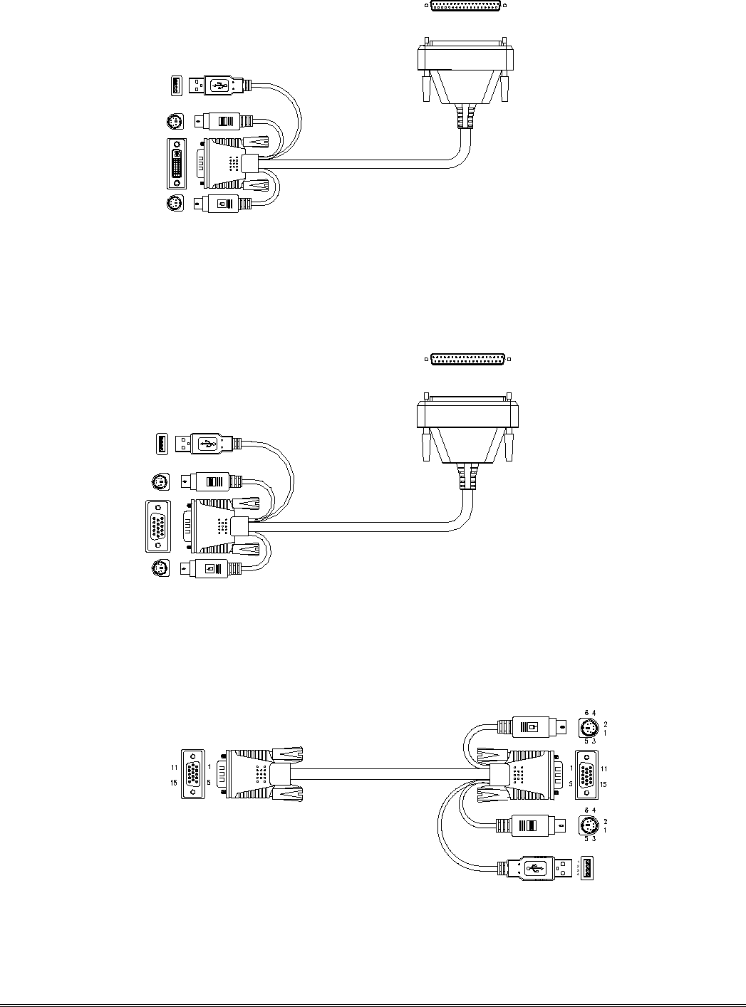
LCD KVM switch single port DVI cable
LCD Connector DB37P
LCD KVM Console User Manual
57
Computer-side DVI-I + USB (Type A)+ PS2 keyboard (purple) + PS2 mouse (green)
LCD KVM switch single port VGA cable
LCD Connector DB37P
Computer-side VGA + USB (Type A) + PS2 keyboard (purple) + PS2 mouse (green)
VGA + USB (Type A) + PS2 Keyboard (Purple) + PS2 Mouse (Green)
LCD KVM Console User Manual
57
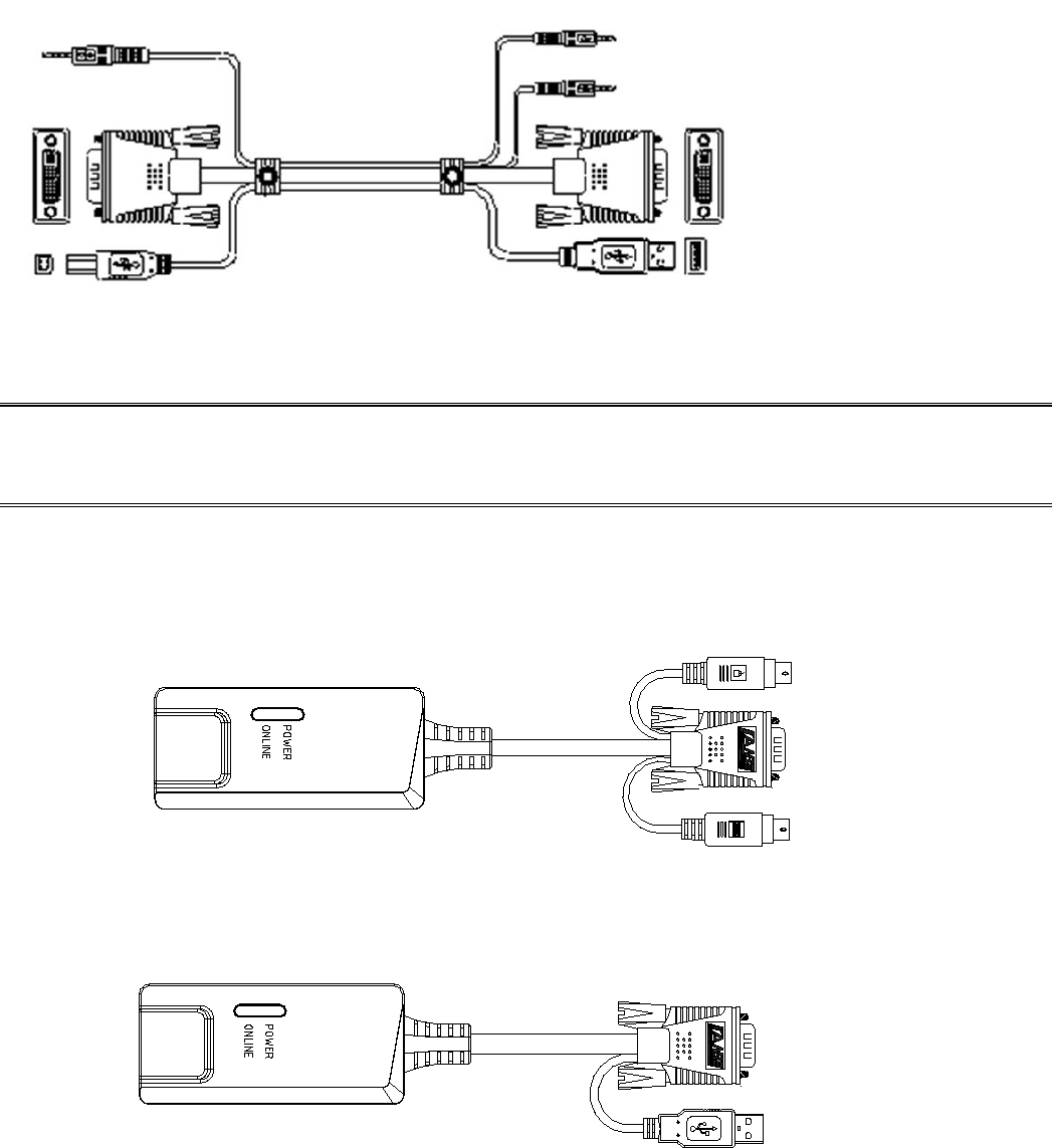
DVI-I + USB(Type A)+ Audio
KVM connection Computer connection
Note: The cable length affects the quality of the display. If you need other lengths of cable, contact the
merchant you purchased to purchase a cable suitable for this switch.
CAT5 connection Dongle VGA + PS2 keyboard (purple) + PS2 mouse (green)
CAT5 connection Dongle VGA + USB (Type A)

LCD KVM Console User Manual
57
Operation System
Operation System
Version
Windows
Windows 2000/XP/2003/2008/Vista/7/10
Linux
RedHat
9.0 or higher Fedora and above, RHEL AS 4, RHEL 5
SuSE
10/11.1、OpenSUSE 10.2; SLES 10 SP1
Debian
3.1/4.0
Ubuntu
7.04/7.10
UNIX
AIX
4.3 or higher
FreeBSD
5.5 or higher
Sun Solaris
8 or higher
Mac
OS 9.0 to 10.6 (Snow Leopard)
Novell
Netware
6.0 or higher
DOS
6.2 or later
More operating system support: please pay more attention to the latest version of the relevant product
compatibility.
LCD KVM Console User Manual
57
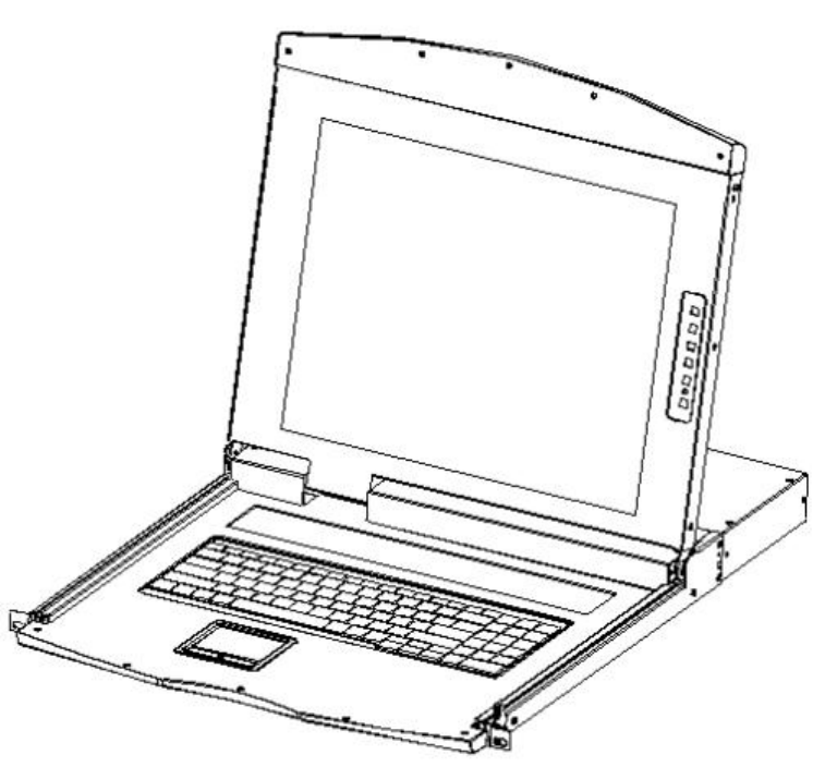
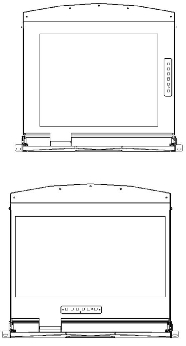
Parts
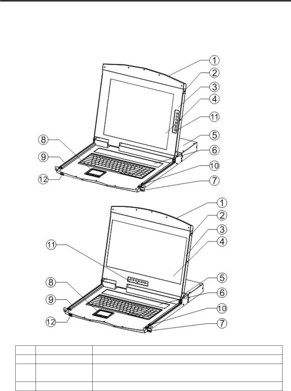
Front View
According to the size of the LCD screen is divided into two styles, as shown below, the components of the
description please see the figure after the serial number table describes the details.
No
Part
Function Description
1
Upper handle
Pull the handle, slide the LCD module out and push it in
2
Lock
Used to lock the LCD module, pull out the module must first
unlock, push into the automatic locking
3
LCD screen cover
Can be opened or closed with the handle, opening and closing
LCD KVM Console User Manual
57
angle of 0-110 degrees
4
LED screen
17 "or 19" LED LCD screen
5
KVM Module
KVM modules are free to replace and remove
6
KVM Key panel
The KVM Port manual switch function is completed by pressing
the key
7
Front mounting
brackets
The LCD KVM can be installed on the cabinet posts with screws
8
Touch Mouse Pad
KVM console mouse, can control the computer's computer
operation
9
Slide rails
LCD module sliding track, can be telescopic freely
10
Keyhole
Corresponds to the latch of the LCD module
11
LCD Keypad
Panel
Used to control the LED screen display adjustment and switch
12
Front USB
Used to access an external USB keyboard or mouse
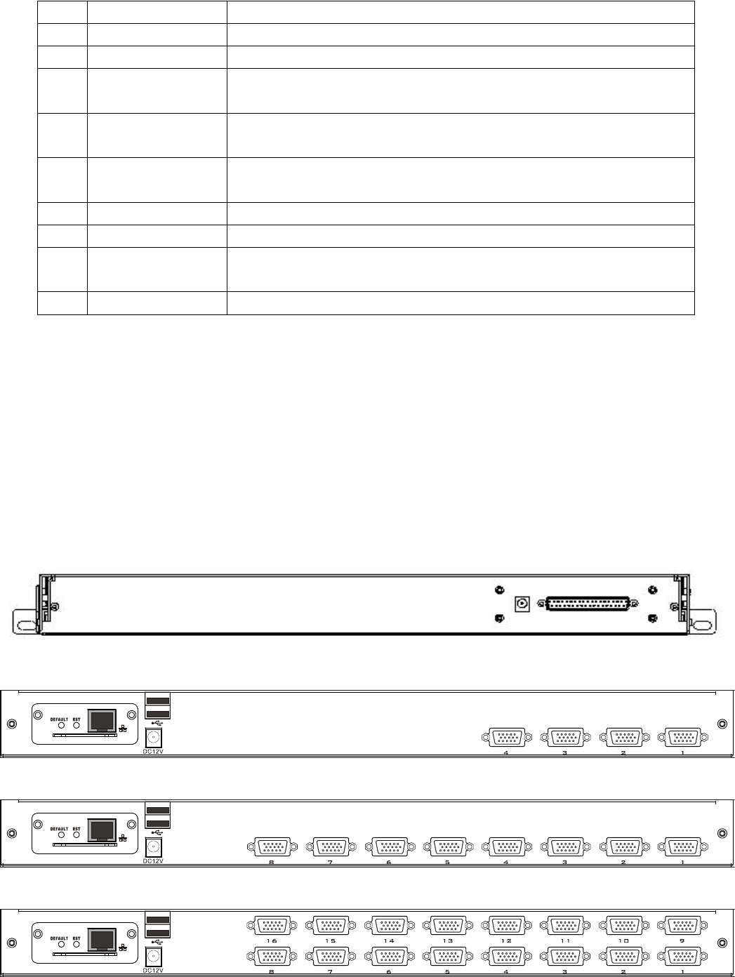
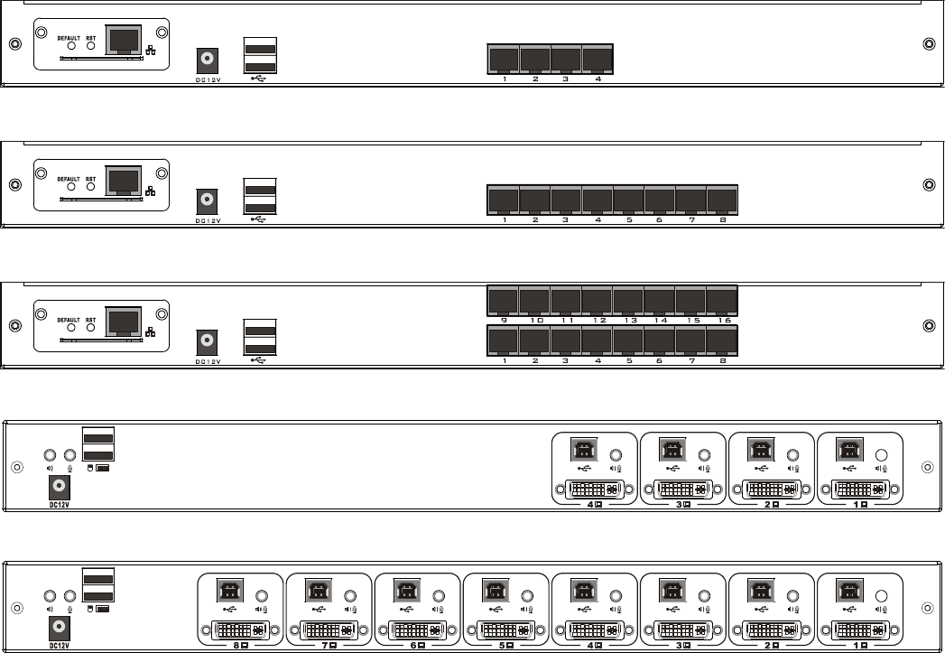
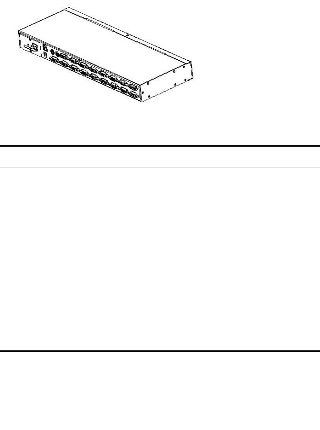
Rear view
The Rear View of this product series is a rear view of the Removable KVM Switch Module, and the
functional description of each Hardware Port (refer to the description of the corresponding KVM Switch
product brochure.)
LCD KVM Single port Rear View
LCD KVM 4 port VGA Rear View
LCD KVM 8 port VGA Rear View
LCD KVM 16 port VGA Rear View
LCD KVM Console User Manual
57
LCD KVM 4 port CAT5 Rear View
LCD KVM 8 port CAT5 Rear View
LCD KVM 16 port CAT5Rear View
LCD KVM 4 port DVI Rear View
LCD KVM 8 port DVI Rear View
According to the type of KVM ,the rear view of the product can be divided into three categories:
VGA Port
This type of LCD KVM switch can be divided into 4 models according to the number of ports: single
port, 4 ports, 8 ports, 16 ports. In addition, the control module of Remote Control IP can be selected
according to the needs.
CAT5 Port
This type of LCD KVM switch can be divided into 3 models according to the number of ports: 4 ports, 8
ports, 16 ports, in addition can be optional Remote Control IP control module.
DVI Port
This type of LCD KVM switch according to the number of Port can be divided into two models:
single-port, four, eight.
LCD KVM Console User Manual
57
Front view of the 4: 3 screen and 16: 9 screen
17inch4: 3 screen
19inch 16: 9 screen
LCD KVM Console User Manual
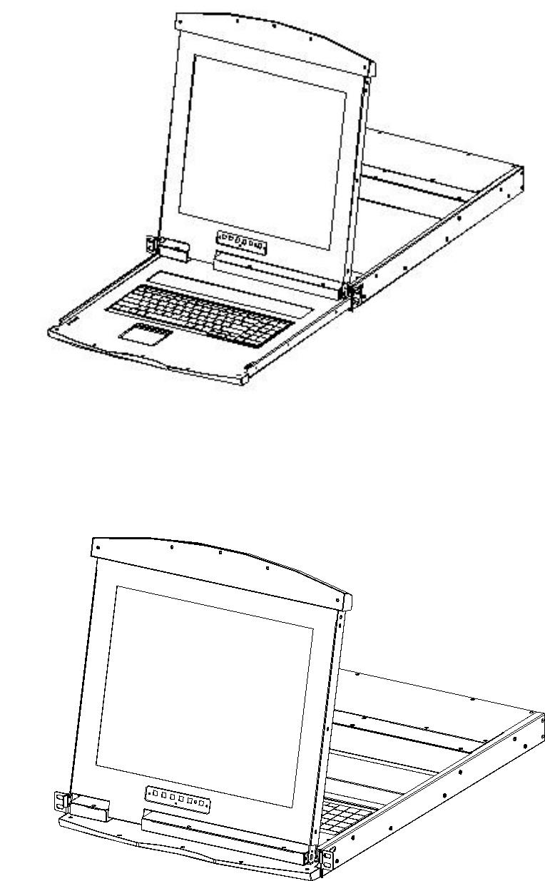
57
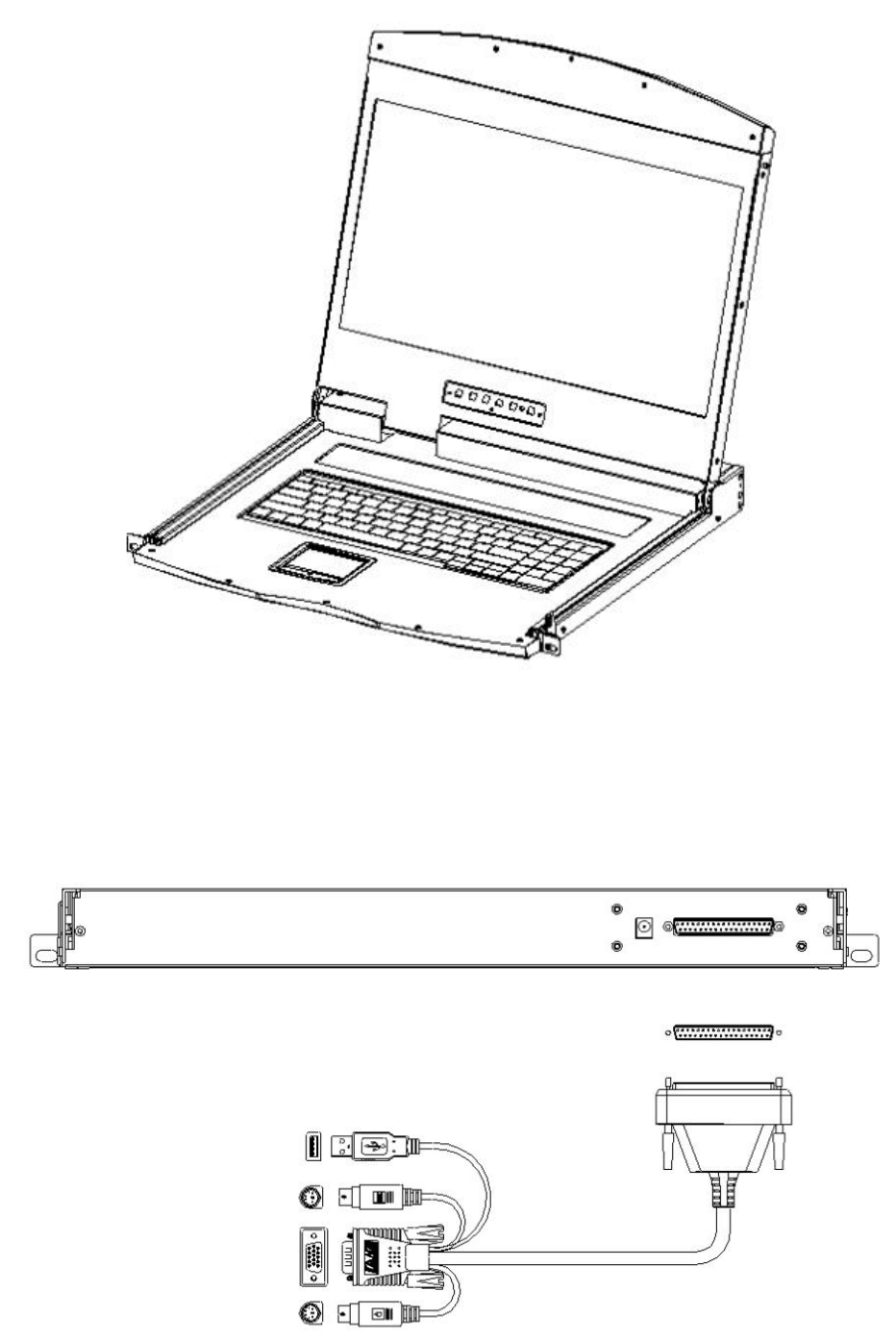
Single –rail &Dual-rail LCD Console display
Single-rail LCD KVM Console
Dual-rail LCD KVM Console
LCD KVM Console User Manual
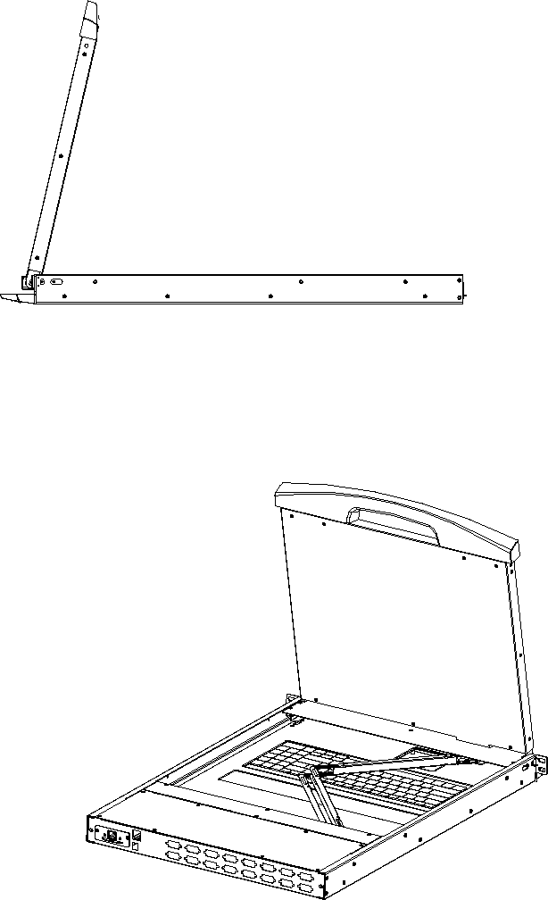
57
Dual -Rail Slide View
Dual-rail overall rear view
LCD KVM Console User Manual
57
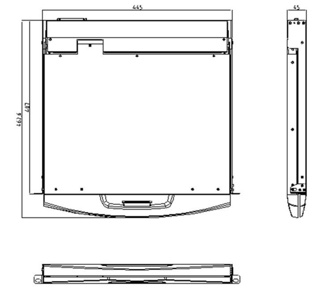
Overall Dimensions of the LCD KVM
Single-rail single port KVM Console dimension:
LCD KVM Console User Manual
57
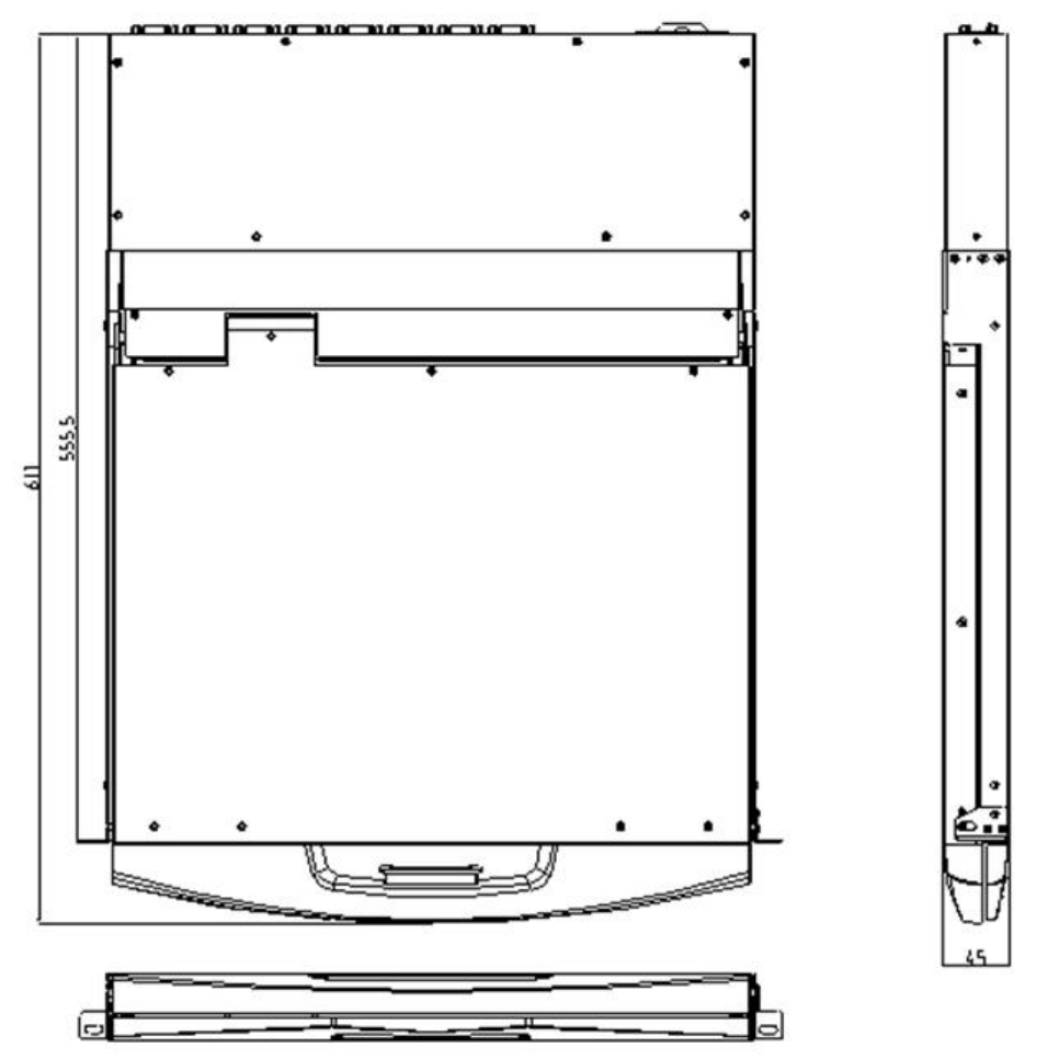
Single –rail multi-ports KVM Console dimension:
LCD KVM Console User Manual
57
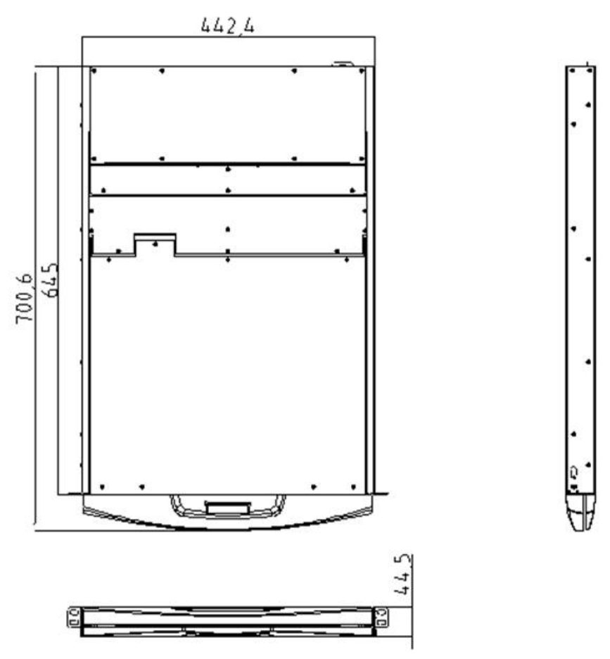
Dual-rail LCD KVM Console dimension:
LCD KVM Console User Manual
57
Chapter 2
Hardware Installation
Stacking and Installation Precautions
1. Important safety information regarding the placement of the LCD KVM switch is
listed in the appendix, please refer to it before proceeding.
2. Before installation, please make sure that all the devices connected to the power supply are
turned off. You must unplug all the power cord of the computer with keyboard power on
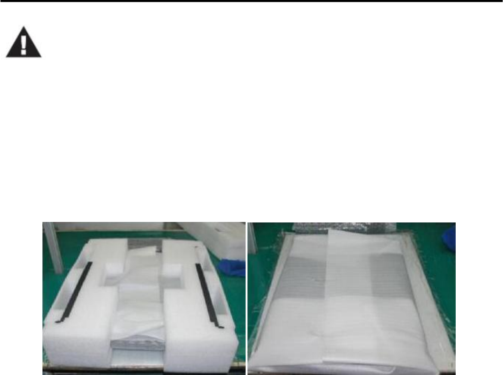
3. LCD KVM switch packing stuffed with stuffing in the process of delivery to protect the product.
Attach the protective film and filler to the LCD module and remove the filler before mounting.
The LCD KVM switch can be placed in any suitable plane and is sufficient to securely support the weight
of the equipment plus additional cables; Please make sure that the plane is clean and free from other debris
that can affect the ventilation and normal operation of the switch.
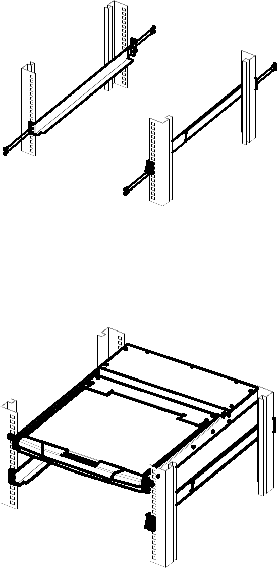
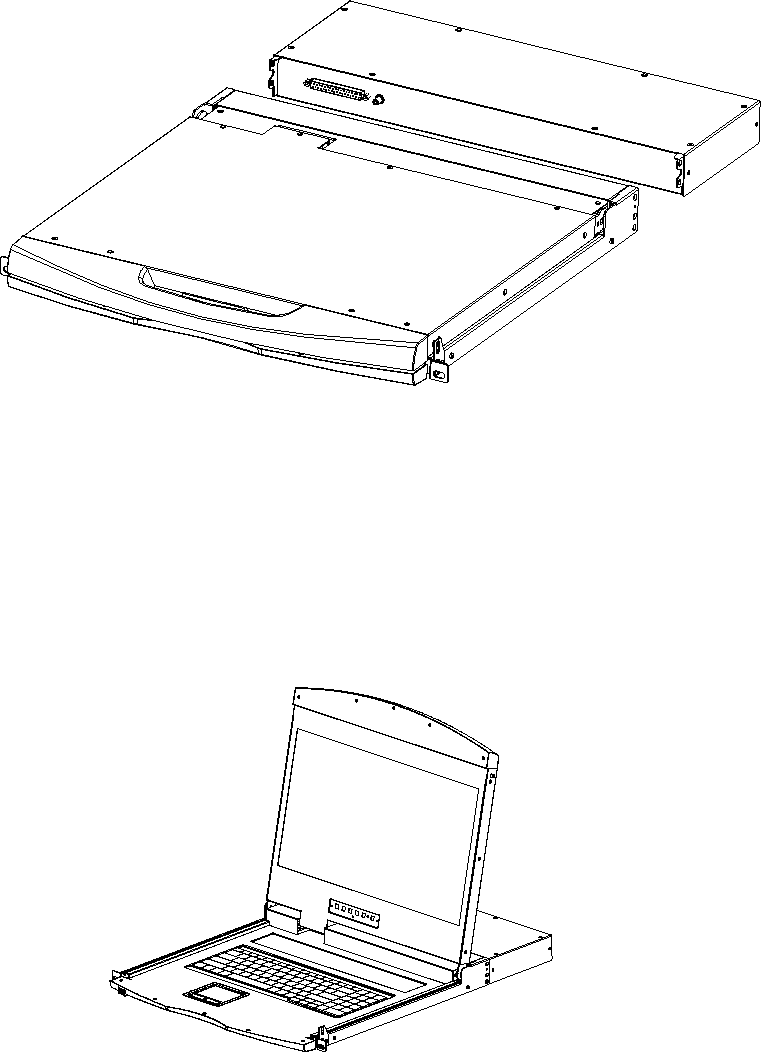
Standard Rack Mounting
1. Remove the mounting brackets and fasten the front bezel to the frame with screws. Slide the back plate
with the rear flange toward the rack until the flange is against the chassis, and then use the screws to secure
the rear flange to the chassis.
LCD KVM Console User Manual
57
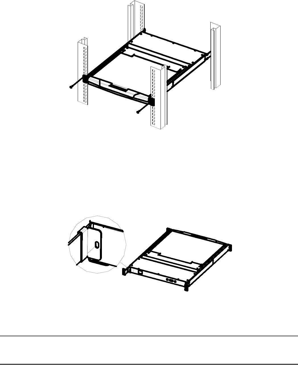
2. Slide the LCD KVM unit onto the support flange, secure the front of the switch to the front of the rack
with the screws provided in the package and lock.
LCD KVM Console User Manual
57
3.Slide the rear connecting slide bracket along the side rails until it reaches the rear of the switch.
4. Use the screws provided in this package to secure the strip to the rear of the switch. At this point, you
have completed the rackmountable LCD KVM switch for subsequent use.
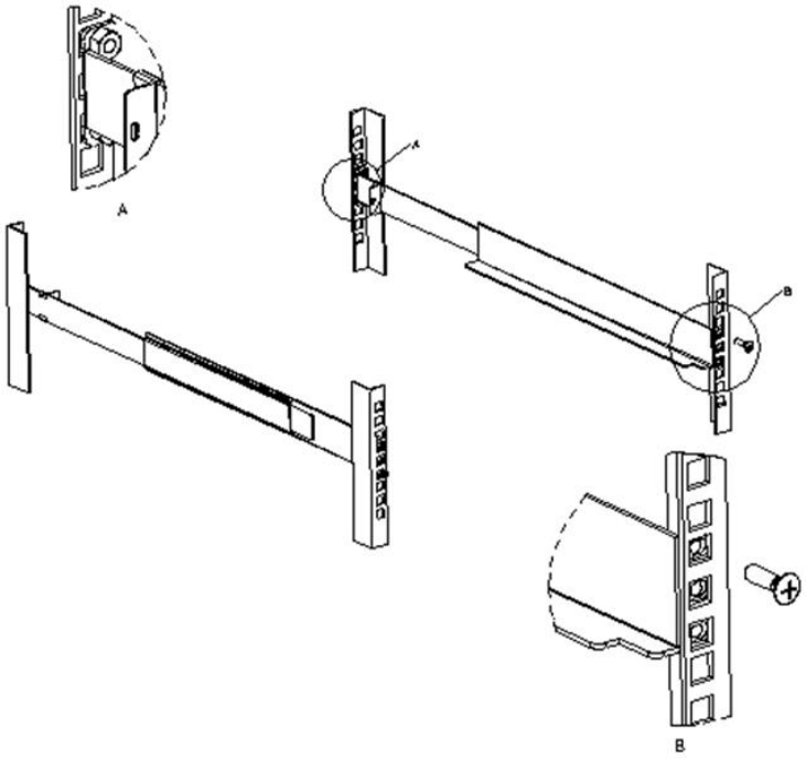
Note: There may be a difference between the two-rail mounting bracket and the single-slide carriage. For
the dual-rail product, please refer to the following figure.
LCD KVM Console User Manual
57
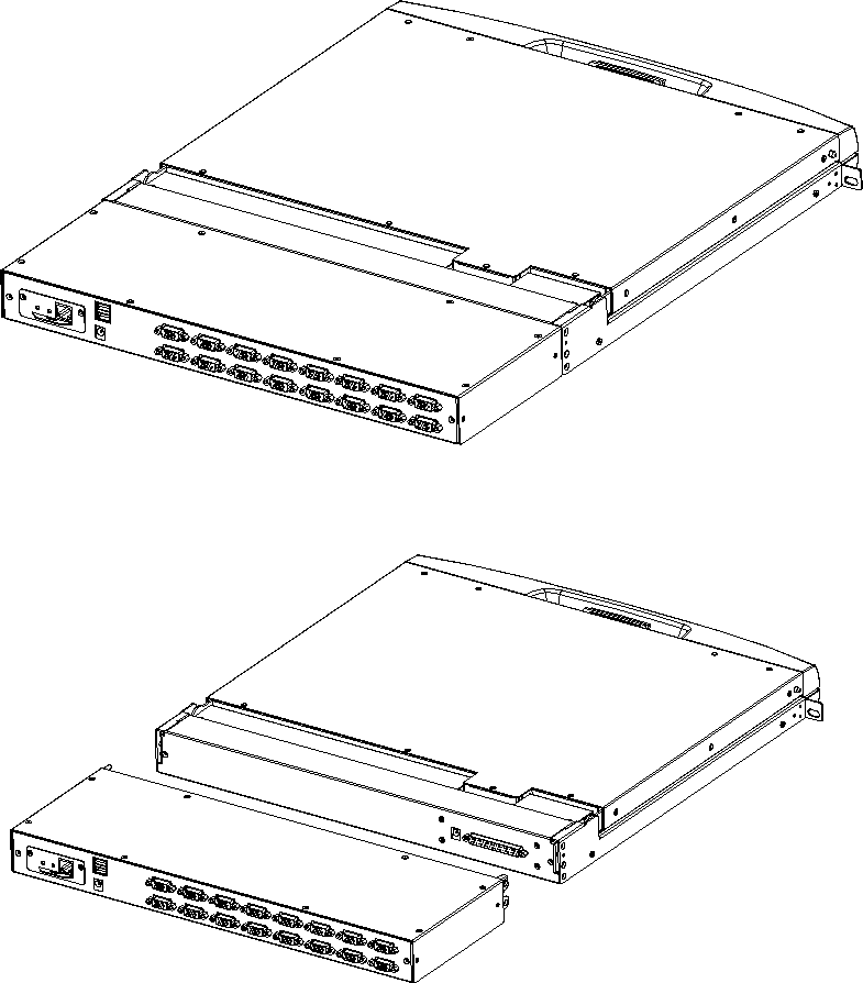
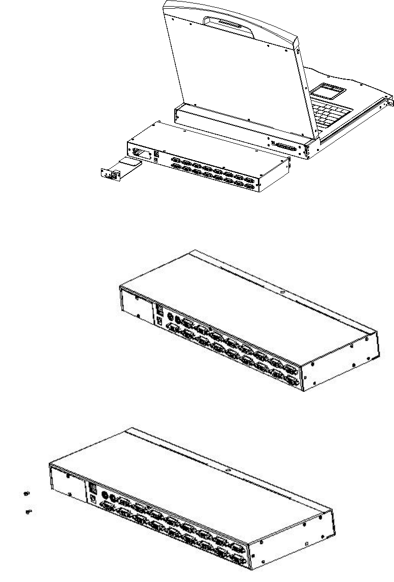
KVM Module assembly & disassembly
This series of LCD screen and keyboard, mouse and the rear part of the KVM part of the components can be
demolished separation, this design allows you to change the KVM components, or KVM components
damaged KVM components dismantled after the return to the manufacturer for repair and replace.
Please refer to the figure for loading and unloading operations:
1. Now put this series of products on the appropriate operating platform, ready for
Screwdriver tools for subsequent use of removable screws.
LCD KVM Console User Manual
57
2. Remove the KVM assembly and the captive screws on the side brackets as shown to separate
the KVM assembly from the front LCD assembly.
3.Please note the connector between the KVM module &LCD during the Removal and installation, or it may
damage the connection interface and equipment function failure.
LCD KVM Console User Manual
57
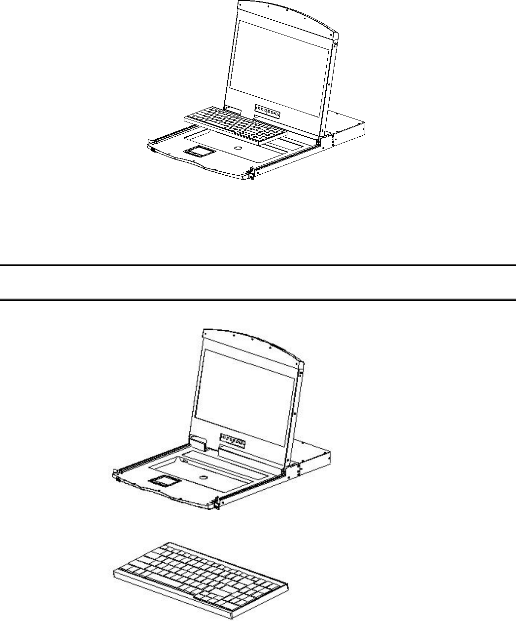
Disassembly of the Keyboard Module
If you need to replace the LCD module part of the keyboard or repair this part, can also be demolished
according to the following diagram.
1.The LCD KVM placed in the rack and fixed, the LCD panel turned up, revealing the keyboard, the
mouse's operating surface.
2.The bottom of the keyboard panel has a circular hole, you can use your fingers through the circular hole,
the top of the keyboard.
LCD KVM Console User Manual
57
3. Pull the keyboard from the limit slot gently, find the connection side of the USB interface, remove
the USB from connection side, the keyboard could be taken out. Thus completing the demolition of the
keyboard module.
Note: If you replace the installation, please first plug the keyboard USB interface, then put the keyboard
module into the limit slot.
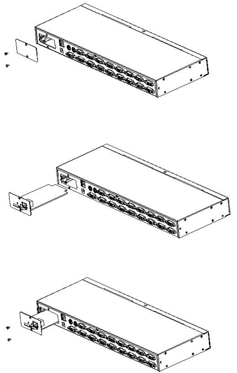
Expansion Module Installation
If you buy a KVM switch, because you need to increase the remote control and operation, you can directly
LCD KVM Console User Manual
57
with the dealer to buy our products supporting the IP module for equipment upgrades and expansion, the
operation method is simple and quick, can quickly enhance the integrated management of KVM Application
ability.
1. find the rear of the device, expansion slot outside the blank position for installation, you need to prepare a
screwdriver for removal and installation tools.
2. Before installation, use a screwdriver to remove the two fixing screws on the blank.
1. Remove the blank after you can see the need to expand the installation of the IP module
placement cavity, keep the screw removed down.
LCD KVM Console User Manual
57
2.Remove the extended IP module and push it gently into the recess in the mounting module
cavity as shown.
3.After pushing the IP module to the bottom, fix the IP module with the two screws that
have been removed before.
4. After installing the IP module, you need to follow the instructions of the IP module
To install the software and configure the IP address of the device before you can connect
the network cable to the switching device. After the installation is complete, you
can access the network to log in. (For details, refer to the IP module's product manual.)
LCD KVM Console User Manual
57
Single Device Installation
Note:Before the installation, make sure that the equipment is powered off. To prevent damage to the
equipment during installation, make sure that all the devices installed are well grounded.
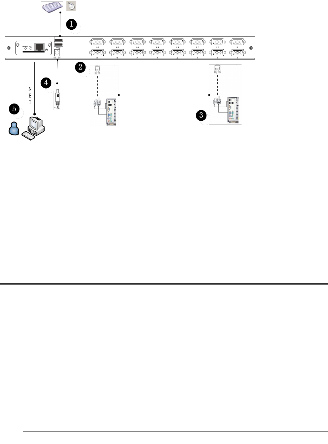
VGA port KVM module installation
To install a single-level KVM, refer to the following online diagrams (numbered in the order of steps on the
online graph) and do the following:
1.Plug your USB keyboard and mouse into the USB console port on the back panel of the switch.
2.Using a set of KVM cables corresponding to the model, plug the VGA connector into the VGA
Port of any available VGA port on the switch.
3.Plug the corresponding VGA video connector, USB or PS2 connector of the KVM cable into
the corresponding port on the PC.
4.Plug the power adapter supplied with this package into the AC power source, and plug the
other end of the power adapter into the power jack on the switch.
5.Connect the network cable to the IP port of the IP module.
6.Turn on the computer.
Note:1. Make sure that all plugs are connected to the same group of KVM connection port jacks (all
connected to Port1, or all connected to Port2).
2.IP module is an optional module of the product. If the product you purchased does not contain
the module, please ignore the related operation in Step 5.
3.Before using the IP module, please make the appropriate configuration and network debugging
after the access to the network you want to connect, or may fail to connect because of
normal remote control. (Refer to the manual of the IP module product manual for how to
use and debug the IP module.
LCD KVM Console User Manual
57
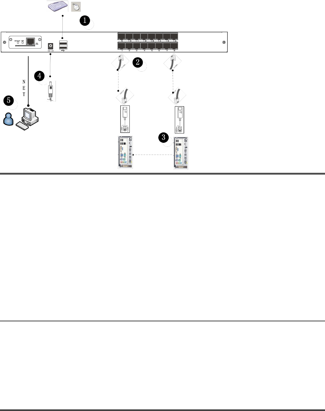
CAT5 port KVM Module Installation
To install a single-level KVM, refer to the following online diagrams (numbered in the order of steps on
the online graph) and do the following:
1. Plug your USB keyboard and mouse into the USB console port on the back panel of the switch.
2.Use a set of CAT5e / 6-wire connectors to plug into any available CAT5 Port on the switch.
3. Plug a CAT5e / 6-wire connector into the CAT5 connector on the Dongle module of the KVM, and
connect the corresponding VGA video connector, USB or PS2 connector of the Dongle cable to the
corresponding port on the PC.
4. Plug the power adapter supplied with this package into the AC power source, and plug the
other end of the power adapter into the power jack on the switch.
5. Connect the network cable to the IP port of the IP module.
6. Turn on the computer.
Note:1. Make sure that all plugs are connected to the same group of KVM connection port jacks (all
connected to Port1, or all connected to Port2).
2. The IP module is an optional module of the product. If the product you purchased does not
include the module, please ignore the related operation in Step 5.
3. Before using the IP module, please make the appropriate configuration and network debugging
after the access to the network you want to connect, or may fail to connect because of normal
remote control. (Refer to the manual of the IP module product manual for how to use and debug
the IP module.)
4.
LCD KVM conversion module is divided into two types: PS2 and USB port, you can connect your
computer to choose the appropriate conversion module to use.
5.Make sure you are connecting to a computer and LCD KVM switches have a good grounding
protection altogether, or it may produce a video display problems
6.For display problems caused by transmission distance, electromagnetic interference, common
ground, etc., it is recommended to use Category 6 shielded network cable to connect and try to
improve the display effect
LCD KVM Console User Manual
57
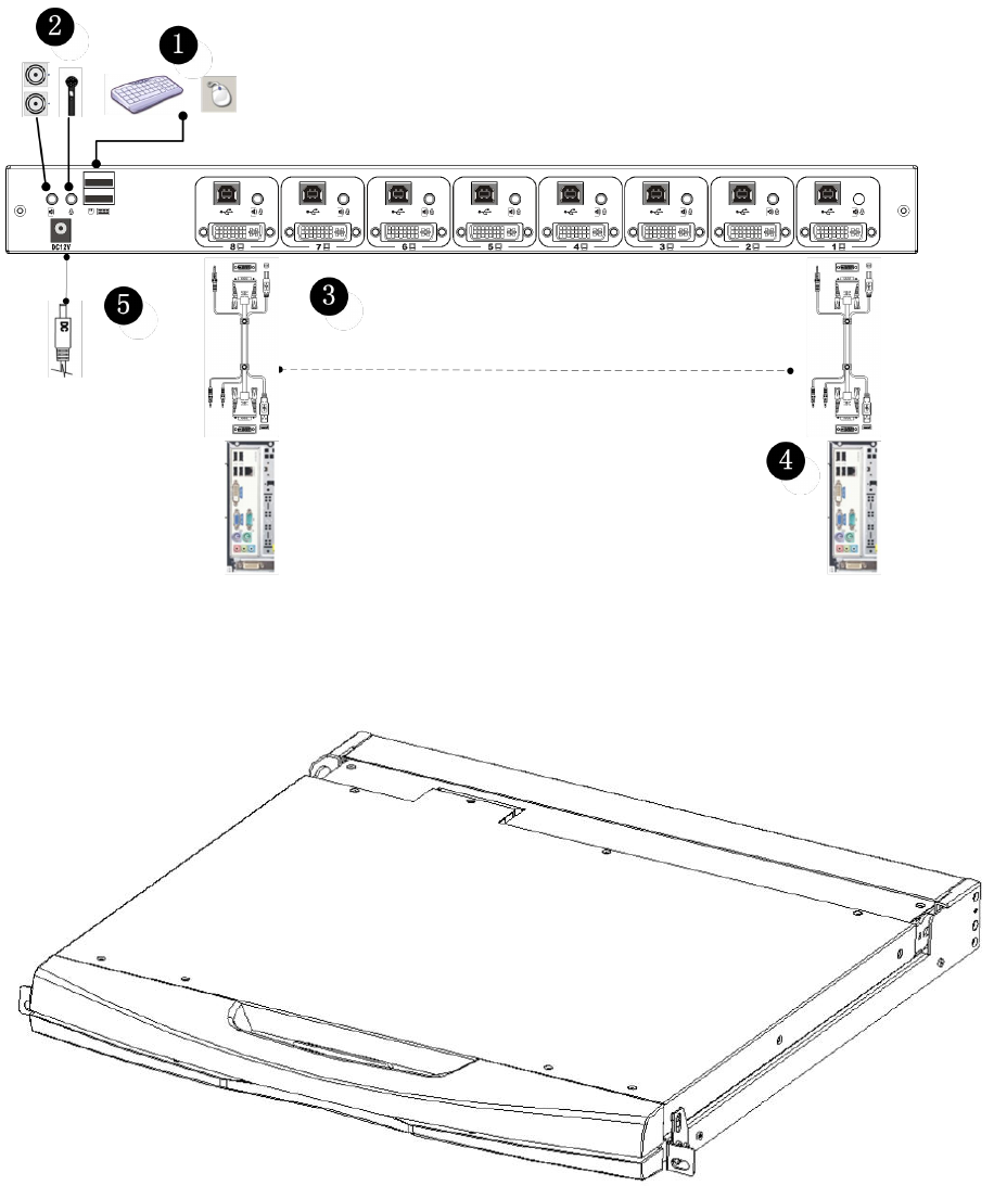
DVI port KVM module installation
To install a single-level KVM, refer to the following online diagrams (numbered in the order of steps on
the online graph) and do the following:
1. Plug your USB keyboard and mouse into the USB console port on the back panel of the switch.
2. Insert the audio cable plug of the microphone and the speaker into the corresponding type
port.
3. Using a set of DVI KVM cable connectors corresponding to this module to plug into any of the available
Port ports on the switch, DVI to DVI port, USB Type B to keyboard port, mouse port, composite audio
plug into the audio jack.
4. Connect the AC adapter to the AC power source, and plug the other end of the power adapter into the
power jack on the switch.
5. Connect the network cable to the IP port of the IP module.
6. Turn on the computer
Note:
1.LCD KVM conversion module is divided into two types: PS2 and USB port, you can connect your
computer to choose the appropriate conversion module to use.
2.Please make sure that the computer and the LCD KVM switch you are connecting to
have a good common earth ground, otherwise a video display problem may occur.
3.For display problems caused by transmission distance, electromagnetic interference,
common ground, etc., it is recommended to use Category 6 shielded network cable to
connect and try to improve the display effect.
LCD KVM Console User Manual
57
Installation of Single Port LCD KVM Switch
LCD KVM Console User Manual
57
Single-port LCD KVM switch choose KVM cables to connect instead of multi-port use KVM module,
divided into two kinds: VGA and DVI according to the port type.
VGA Single port LCD KVM
LCD KVM Console User Manual
57
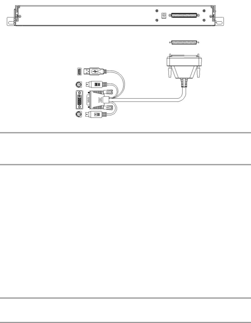
DVI single port LCD KVM Switch
Note:Connect the DP37 port to the corresponding port on the back of the LCD, and then connect the video
port of the other end to the video port of the computer. Then connect the port of PS2 or USB to the
corresponding keyboard and mouse port of the computer, then power the computer and the LCD KVM
switch.
Cascade Device Connection
This product can be cascaded to increase the number of control devices, combined with IP remote control
mode can be flexibly used in a variety of user environment requirements.
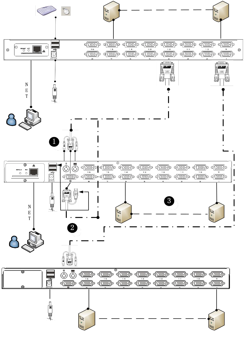
VGA Port LCD KVM Switch Cascade
In the VGA switch Cascade mode, the keyboard, mouse and computer connections is same with the
stand-alone connection, this part will not repeat them, the number part of the description is as follows:
1. A cascaded KVM switch can be connected in two ways by using a USB KVM cable (as shown
in connection number 2 in the figure) or a PS2 KVM cable (as shown in connection number
1 in the figure) Connect to the upper-level switcher.
2.The number of computers connected to each level can be freely increased or decreased according to your
requirements. Refer to the connection method shown in figure 3.
3. Between the level of IP module can be optional remote control, can also be handed over to the KVM
switch from the top of the local and remote as a unified control and management operations.
Note:
This product cascade mode is divided into two levels, so you need to set the cascade connection mode
switch OSD Menu with two levels of hotkey for two different hotkey combinations, or the OSD can not be
started when cascade.(Refer to the OSD chapter for details on the OSD Hot Key settings.)
Connection diagram please see the following figure (VGA port LCD KVM switch cascade)

LCD KVM Console User Manual
57
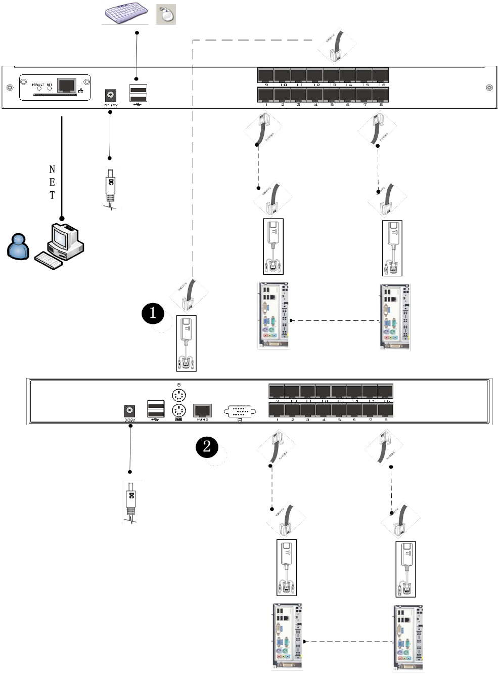
CAT5 Port LCD KVM Switch Cascade
In switch cascade mode, the keyboard, mouse and computer connections and stand-alone connection is the
same, this part will not repeat them, the number part of the description is as follows:
1.The cascade KVM switch, have two connection methods, the use of USB KVM conversion module cable
or PS2 KVM conversion module cable and a switch to the next level to connect. (Refer to the description
of the CAT5 KVM switch product manual for how to connect the converter module.)
2.The number of computers connected to each level can be changed according to your needs. Refer to the
connection port shown in figure 2, which is the connection port of Remote Control mode. It can provide
the user to connect the control device through Remote Control console. Remote Control Port switcher
usage and connection method(Refer to the CAT5 KVM switch product manual for instructions.))
3.IP modules can be selected for remote control, and can also be controlled by local and remote KVM
switches from the upper layer as a unified control and management operation.
Note:This product cascade mode is divided into two levels, so you need to set two levels of OSD Menu
hotkey for two different hotkey combinations in cascade mode, otherwise the cascade connection can not
start the OSD normally. The OSD Hot Key settings are described in detail in the OSD chapter.)
Please make sure that your computer and LCD KVM switch are well grounded. Otherwise, the video
display problem may occur. For the display problems caused by transmission distance, electromagnetic
interference, common ground, etc., it is recommended to use Category 6 Screen cable to connect, try to
improve the display.
LCD KVM Console User Manual
57
The connection diagram is shown in the following figure (CAT5PortLCD KVM Switch
Cascade).
LCD KVM Console User Manual
57
VGALCD KVM Switch Cascade
CAT5LCD KVM Switch Cascade
LCD KVM Console User Manual
57
Chapter3
Basic Operation
Hot Plug
The KVM switch supports hot-plug, removing and removing components by unplugging the cables
connected to the computer's port without shutting down the switch. To make the hot swap function work
properly, follow these steps:
Hot – Plug Computer Connection
In order for OSD Menu to correspond to the KVM connection port changes, you must reset OSD Menu to
display the latest connection port information, OSD menu settings. Please refer to the OSD Menu section for
more information about functions and usage.
Note: If your computer's operating system does not support hot-plug functionality, this feature may not
function properly.
Hot – Plug Console Port
This product also provides keyboard, mouse and display hot-plug function. This product provides keyboard
and mouse port for two interface types. Users can select the corresponding device connection type according
to their usage and carry out corresponding control operation.
Note: If you access the USB and PS2 keyboard, mouse device, you do not have to use two types of devices,
otherwise, may cause the accused computer equipment mouse and keyboard response exception.
Connection Port Selection
The KVM switch can be used to quickly switch to any computer connected to the KVM in three modes:
manual key selection, OSD Menu screen selection, and hotkey selection.
Switch the Selection Manually
Use the buttons on the front control panel to select a
port.
LCD KVM Console User Manual
57
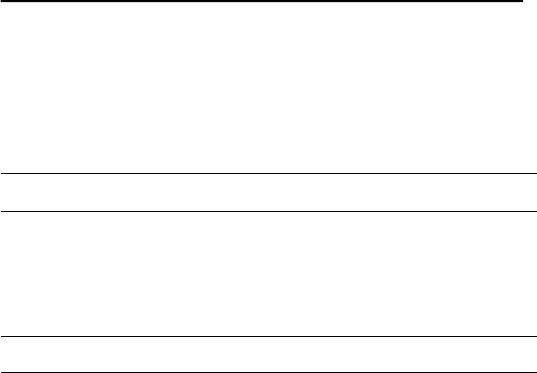
KVM switch button located in the top of the keyboard operating area, divided into three blocks, from left to
right in order is the online indicator display area, Port switch to select the display area, Port switch digital
button area.
Online Indicator Display Area
The LEDs in the display area are lit when the controlled computer connected to KVM Port is connected
to the line. The LED indicating the port number is illuminated and you can see the KVM online Port
status.
Port Switch the Display Area
The digital LED indicator in the display area shows the port serial number of the current working port
when the working status is displayed, or the numeric key serial number you input when the key switch
port changes.
Port Switches the Numeric Keypad Area
This area has the numeric keys of [0] - [9] and [RST] (reset button), [ENT] (confirm button), the
number keys are used for Port selection, input the corresponding port number, 【ENT】to finish the
switch of Port. To reset the KVM switch, you need to click [RST] for 3-5 seconds to complete the KVM
switch restart.
OSD Menu Screen Selection
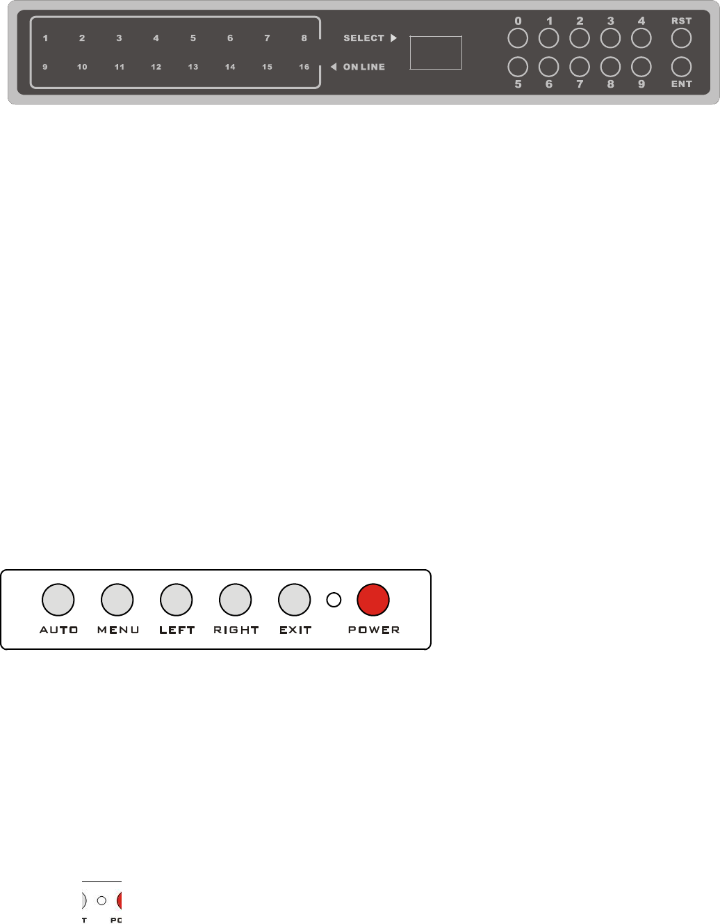
LCD OSD Menu key operation
【AUTO】Press the key to set the display setting for the screen to automatically
adjust to the resolution
【MENU】Press the key to perform the main function OSD Menu of the LCD screen,
to select and set various functions of the screen
【LEFT】Press the key to select the direction of the OSD menu, and move the current
selection to the left by one unit
【RIGHT】Press the key to select the direction of the OSD menu and move the current
selection to the right by one unit
【EXIT】Press to exit the OSD menu
【POWER】Pressing the button allows you to turn the LCD screen on and off
LED display for the LCD screen status indicator, you can indicate three working status:
red, green, do not show the state. "Red" indicates that the LCD screen has been powered, but no
video signal input. "Green" indicates that the LCD normally displays the video signal of the
controlled computer. "No display" means the LCD screen has been powered off.

LCD KVM Console User Manual
57
KVM OSD Menu operation
(Refer to the OSD Operation chapter for more information.)
Hotkey Selection
This product offers four hotkey switching methods:
【SCRLL】+【SCRLL】+【NUM】
【CTRL】+【CTRL】+【NUM】
【ALT】+【ALT】+【NUM】
【SHIFT】+【SHIFT】+【NUM】
The default hotkey toggle key combination is [SCRLL] + [SCRLL] + [NUM] where [NUM] is the keyboard
number 1-16, the keyboard combination hotkey input complete carriage return completed the command
transmission, KVM switch will switch the corresponding number Of the Port computer. If you want to
change the key combination of the hotkey, you can set and change it in the corresponding option of OSD
Menu.
Power Off and Restart
If you need to power off the KVM switch, do the following before turning it back on:
1.Unplug the power supply to the KVM.
2.Turn off all computers connected to the KVM switch.
3.Wait about 10 seconds, then reconnect the KVM switch.
4.Turn on the computer.
Note: If the PS2 KVM cable is connected to the PC, you must connect the PS2 cable to the PC before
powering on. Otherwise, the keyboard and mouse will not operate normally.
LCD KVM Console User Manual
57
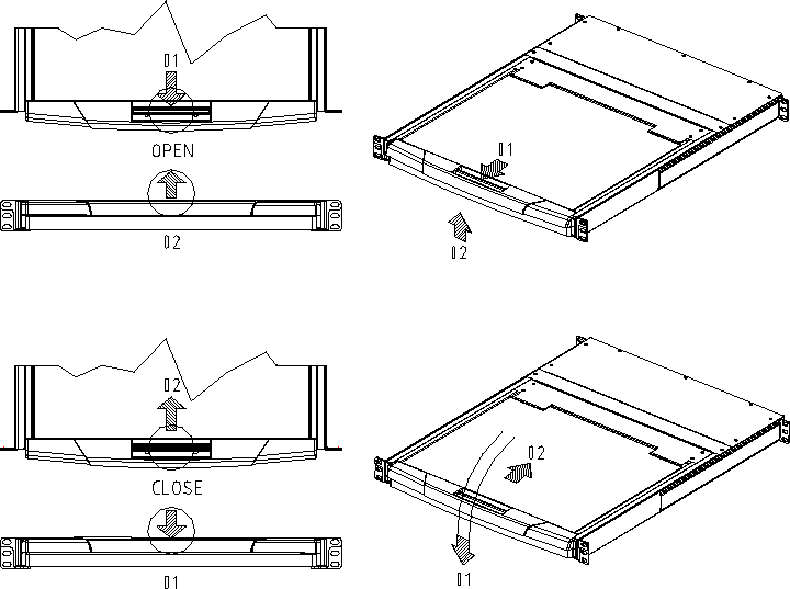
Open Way of LCD Screen
When using, the LCD assembly can be unlocked from the side track by the handle of the upper part of
the LCD unit. After unlocking, the LCD module can be pulled out from the slide rail. (Refer to the
diagram above for operation)
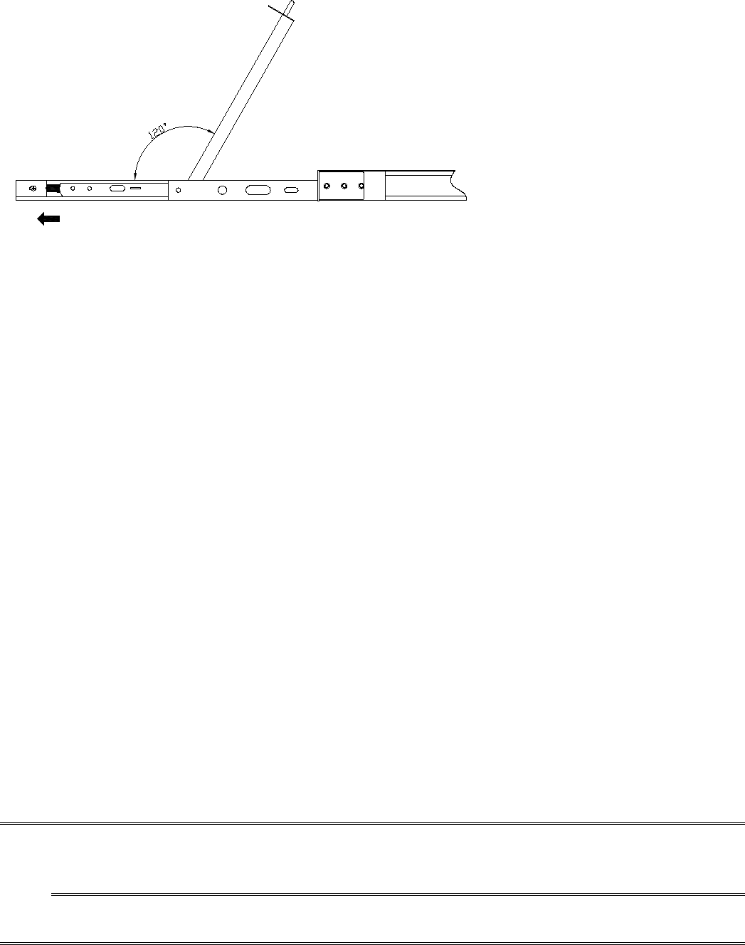
To open the LCD display screen, you can flip the screen upwards to fit the viewing angle only. The
maximum angle that the LCD screen can be opened is 105 degrees -120 degrees. You can view the
screen at any angle you like.
LCD KVM Console User Manual
57
UNLOCK
AUTO LOCK
The screen will automatically pull out the slide after the brake lock device to prevent the random sliding
LCD screen components to bring the instability and may cause damage to the user collision. After the
brake lock is activated, the LCD screen will limit the operation of pushing the slide rail. If you want to
do the push-in operation of the LCD module, the unlocking action must be done first, and the unlocking
switch is on both sides of the slide rail. (Please refer to the figure above for the specific operation). After
unlocking, the LCD assembly can be pushed into the slide rail.
Note:1.Push the LCD assembly into the slide, the unlock action and push action should be
careful, improper operation may clip your finger.
2.When using the keyboard or mouse, do not use the body to depress the LCD module
Otherwise, it may cause the slide rail to deform or not be able to be pushed into
the slide rail

LCD KVM Console User Manual
57
Chapter4
OSD Operation
OSD Introduction
OSD (On Screen Display), provides a menu driven interface to handle the computer switching procedure to
provide instant access to any computer on the installation.
OSD Log in
The OSD function provides a two-level (administrator / user) password mechanism. The factory default
setting is no need to login password authentication, so you are the first time to open the OSD main menu, no
need to enter the login password to enter the OSD main menu screen for the corresponding operation. If you
want to add this function, you can enter the OSD menu, in 【F6】"SET" option to set the login password is
set successfully, the subsequent login requires the correct administrator / user password to enter the OSD
menu Interface operation. When you enter the setting options, some functions may need to be edited and
modified by the administrator. The default administrator password is admin. You can also modify and
change them as needed.
OSD Hot-Key
By default, you can type the [CTRL] key twice to have the OSD menu appear on the screen of the controlled
display and see the connection information and status information about the connected computers on the
KVM switch.
Note: You can change the keyboard hotkey on the OSD menu according to your needs. This product
provides 4 sets of optional OSD menu hotkey combinations. You can select the operation according to your
needs. (Please refer to the OSD menu for detailed description. )
LCD KVM Console User Manual
57
OSD Main Menu
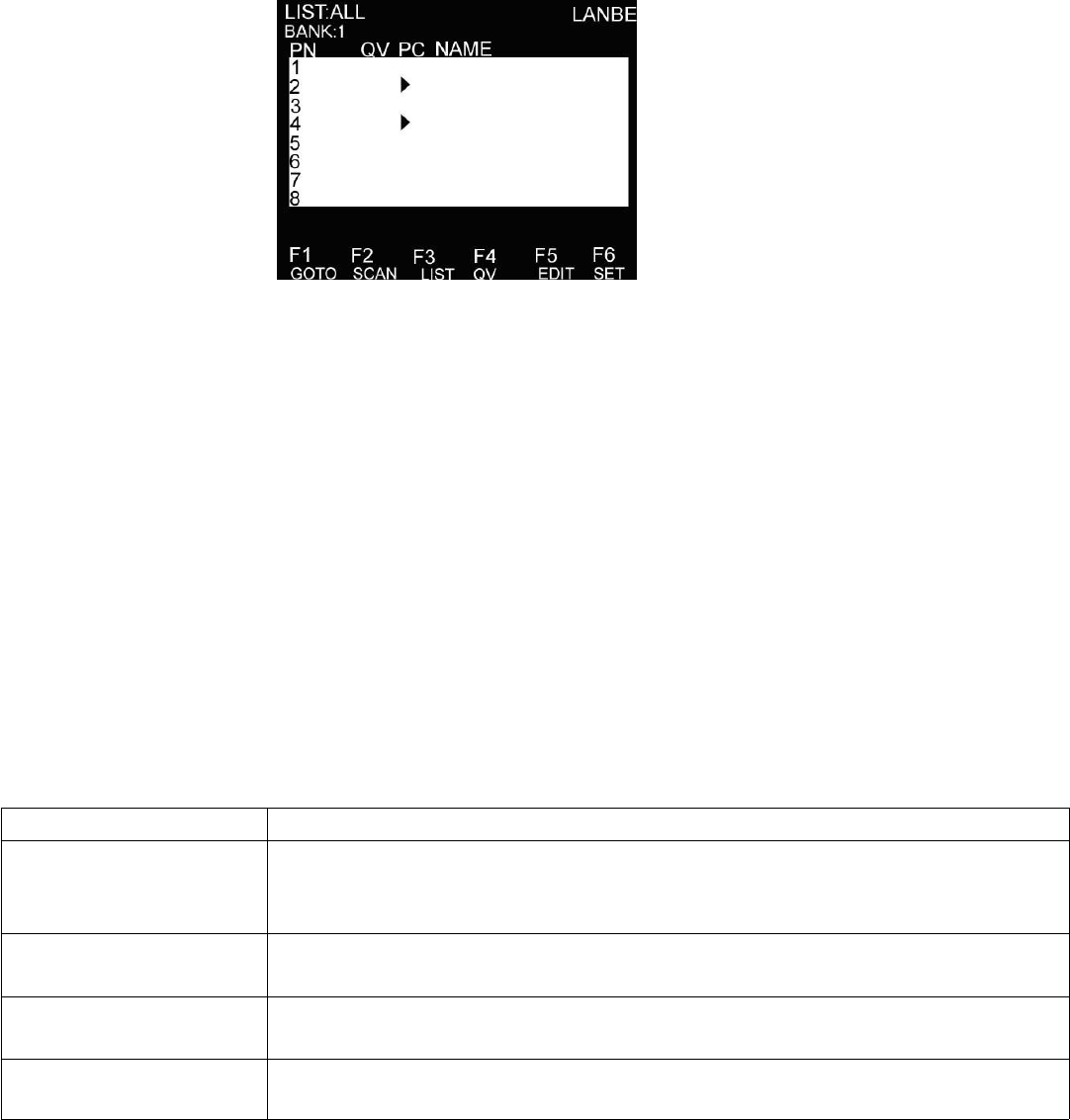
Active OSD, following picture will be shown on the screen:
【F1】--- 【F6】at the bottom of the screen is the function setting of OSD menu, and corresponding
operation and setting of corresponding function by keyboard.
After entering the OSD main screen, the port number in the center of the screen is the port number of
the selected PC. To move up and down through the list one line at a time, use the【↑】【↓】Arrow Keys,
press 【Enter】to select the switch port.
Please press【Esc】to exit the OSD menu interface
To move up or down a row in the list, use the【↑】【↓】arrow keys. If the number of rows in the list is
larger than the number that the screen can display, the screen scrolls.
When the OSD menu is closed, a small blue window will appear on the screen showing the port number
that is currently switched to.
OSD Main Screen Headings
Heading
Explanation
PN
This column lists the port numbers for all the CPU ports on the installation. The
simplest method to access a particular computer is to move the highlight bar to it,
then press [Enter].
QV
If a port has been selected for Quick View scanning, an arrowhead symbol
displays in this column to indicate so.
PC
The computers that are powered on and are on line have an arrowhead symbol in
this column to indicate so.
NAME
If a port has been given a name, its name appears in this column.
OSD Function
OSD functions are used to configure and control the OSD. For example, you can: rapidly switch to any port;
scan selected ports only; limit the list you wish to view; designate a port as a Quick View Port; create or edit
LCD KVM Console User Manual
57
a port name; or make OSD setting adjustments.
To activate the OSD function key:
1. Press any function key【F1】--- 【F6】at the bottom of main screen to input the function key.
2. On the sub-menu, move the selection column to the option, and then press the {Enter} key.
3. Press the【Esc】key to return to the previous menu.
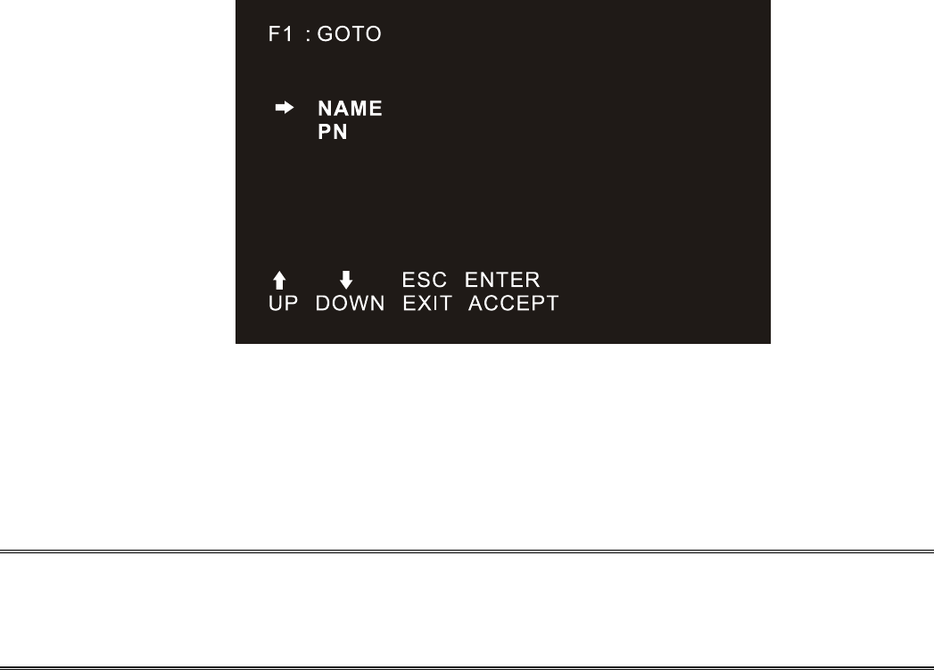
F1 GOTO:
Press the 【F1】key to start the GOTO function. The GOTO function allows you to switch directly to the
connection port by typing the port name or its port number.
1. To use “NAM” method, move highlight bar to “NAME”, press 【Enter】, input name of a port, then press
[Enter] to confirm.
2. To use PN method, move highlight bar to “PN”, press 【Enter】, input port number, then press 【Enter】
to switch. If the port number is invalid, it will remind the user to input again.
Note:1. When keying name, if there is a matching name, the matched name will appear on the screen, just
press [Enter] to switch to that port.
2.In the "PN" port input box, only allow the input of numbers, such as the input of other characters are
regarded as invalid input, and can hear the equipment issued by the warning tone.
To return to main menu, press [Esc].
F2 SCAN:
The "SCAN" function allows you to perform automatic port scanning of the connected computers. Users can
switch ports in order to view the corresponding port computer status.
The SCAN function can automatically scan from current selected port, the scan interval can be set by
users.
When scanning, a small window on the screen indicates the current port number.
LCD KVM Console User Manual
57
Press [Space] to stop scanning, and the KVM switches to the port last scanned.
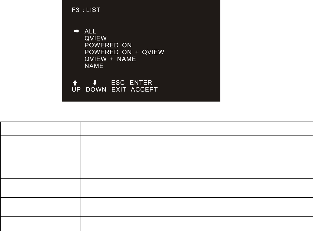
F3 LIST:
The LIST function lets you broaden or narrow the scope of which ports the OSD displays on the main
screen.
Many of the OSD functions only operate on the computers that have been selected for listing on the main
screen with this function. The choices and their meanings are given in the table below:
Choice
Meaning
ALL
Lists all of the ports on the installation.
QVIEW
Lists only the ports that have been selected as Quick View Ports.
POWERED ON
Lists only the ports that have their attached computers powered on.
POWERED ON +
QVIEW
Lists only the ports that have their attached computers powered on and have
been selected as Quick View Ports.
QVIEW + NAME
Lists only the ports that have been selected as Quick View Ports and have
name.
NAME
Lists only the ports that have names.
Move the highlight bar to the choice you want, then press [enter]. An icon appears before the choice to
indicate that it is the currently selected one.
After you make your choice and press [Enter], you return to the OSD main screen with the newly formulated
list displayed.
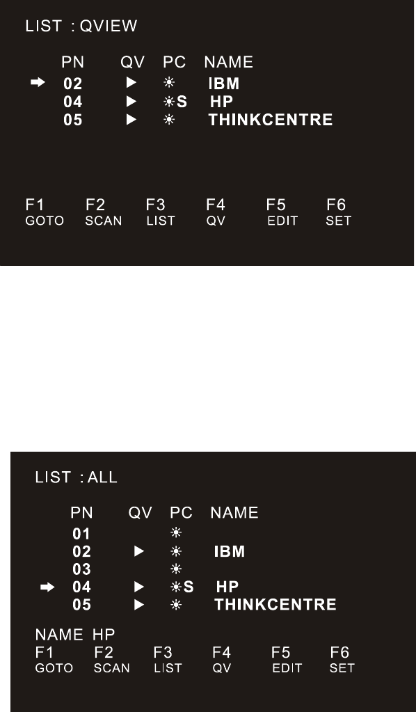
F4 QV:
QV function can select port as Quick View.
LCD KVM Console User Manual
57
Move the highlight bar to a port, press [F4], an icon of up triangle appears. Press [F4] again, the icon
disappears.
F5 EDIT:
EDIT function creates or edits the name of a port. Press [F5], a pink edit box will appear on the screen. Input
name, and then press [Enter], the port is set a name and it will also appear on the screen.
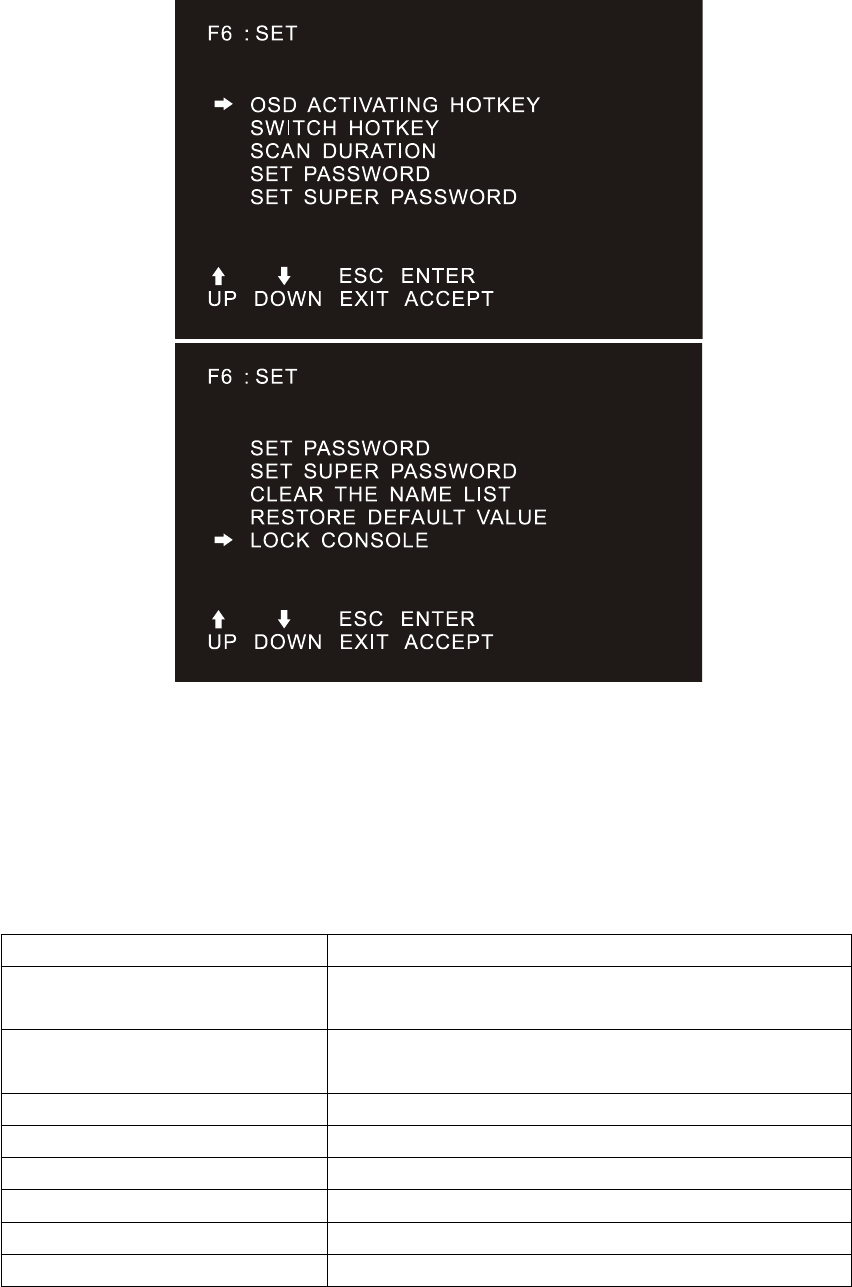
F6 SET:
SET function settings can be set to the administrator and the user to set the OSD menu. The related functions
and user rights related settings, such as management settings login password, display mode, switch hotkey
adjustment and so on.
LCD KVM Console User Manual
57
To change your settings:
1. Move the selection column to this option, press 【Enter】to enter a setting option.
2.After selecting an item, the sub-menu and the further options provided will appear. To select it,
double-click the mouse or move the selection column to the option, and then press the [Enter] key, an icon
will appear. Select the option before to indicate that the item has been selected. The settings are described in
the following table:
Settings
Function
OSD ACTIVATING HOTKEY
OSD Menu Activates hotkey combination selection
settings
SWITCH HOTKEY
KVM port switch hot-key combination selection
setting
SCAN DURATION
Port scan dwell time setting
SET PASSWORD
User login password settings
SET SUPER PASSWORD
The administrator login password settings
CLEAR THE NAME LIST
Clear the port name setting
RESTORE DEFAULT VALUE
Reset
LOCK CONSOLE
OSD Menu Password Login Function settings
LCD KVM Console User Manual
57
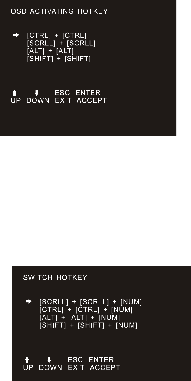
OSD ACTIVATING HOTKEY
It provides you with four hotkey combinations:
You can use the keyboard 【↑】 【↓】to move cursor to select, and then press 【Enter】key to save.
The default is to use 【CTRL】【CTRL】as the OSD menu start hotkey.
SWITCH HOTKEY
It provides you with four hotkey combinations:
【SCRLL】【SCRLL】【NUM】、【CTRL】【CTRL】【NUM】、【ALT】【ALT】【NUM】、
【SHIFT】【SHIFT】【NUM】You can use the keyboard 【↑】 【↓】to move cursor to select, and
then press 【Enter】key to save. The default is to use【SCRLL】【SCRLL】【NUM】as the OSD menu
start hotkey.
【NUM】is the numeric keypad of the keyboard. The valid numeric range is 【1】-【16】.
LCD KVM Console User Manual
57
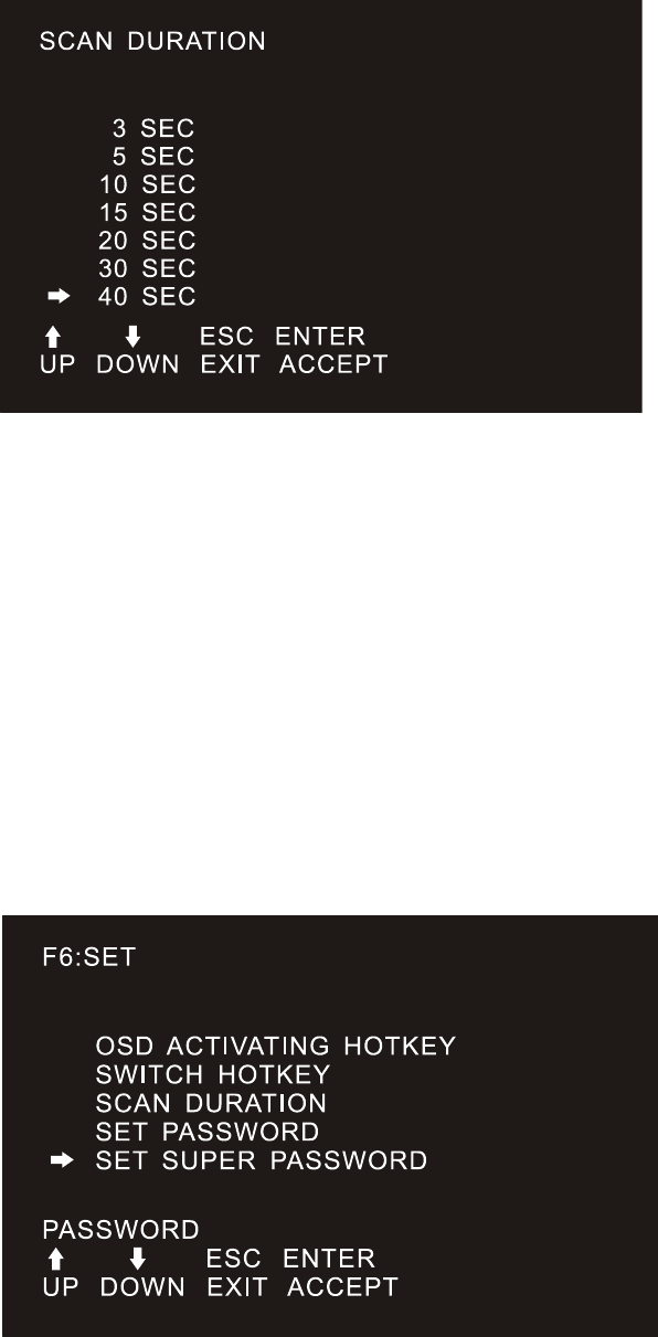
SCAN DURATION
Duration for scanning one port.
Options are 3 seconds, 5 seconds, 10 seconds, 15 seconds, 20 seconds, 30 seconds, 40 seconds, 60
seconds. Move the highlight bar to an option and press [Enter] to select it.
SET PASSWORD
Set new password.
First enter old password, then enter new password and confirm it. The new password is set. If error
occurs, the screen will remind users.
SET SUPER PASSWORD
When setting the administrator password, you need to enter the correct password. Before new password
is updated, input the previous password twice, the new password to take effect
LCD KVM Console User Manual
57
CLEAR THE NAME LIST
This function clears the name of a port in the OSD menu. If you use this function, all the port names
will be emptied, so please do it carefully. When doing this, you need to verify the password of the
administrator, input 【Y】key, then press【Enter】to confirm the operation. To cancel this operation,
input【N】key, and then press【Enter】to confirm the cancel operation, or keyboard input 【Esc】directly
back.
RESTORE DEFAULT VALUE
Restore settings to default value. This setting will make all the OSD menu options to restore the initial
settings, so please be careful to do this. When doing this, you need to verify the password of the
administrator, input 【Y】key, then press【Enter】to confirm the operation. To cancel this operation,
input【N】key, and then press【Enter】to confirm the cancel operation, or keyboard input 【Esc】directly
back.
LOCK CONSOLE
You cannot switch or scan after you lock the console (including switch by push button on the panel or
OSD). You need to enter password to set.
Note: After Locking the console, you can also unlock the console by this option. It also needs password
verification.
(Descriptions of the OSD Menu functions may vary. Refer to the description of each interface
KVM switch manual for details.)

LCD KVM Console User Manual
57
Appendix
Safety Instruction
In General
This product is for indoor use only.
Please read all the instructions for future reference.
Follow all the warnings and instructions on the device.
Do not place this equipment on any unstable surface (such as cart, stand, table, etc.). If this equipment
falls, it will cause serious damage.
Do not use this equipment near water.
Do not place this equipment near or over the radiator or heating equipment.
The enclosure is provided with slots for heat dissipation and ventilation. To prevent overheating during
operation, do not block or cover the openings.
Do not place the device on a soft surface (such as a bed, sofa, blanket, etc.). This will block the fan
opening and can not be placed in a sealed environment unless proper ventilation is provided.
Do not spray any liquid on the device.
Before cleaning, please unplug the power from the wall socket. Do not use any liquid or foam cleaner.
Use a damp cloth to clean it.
Please use this equipment according to the type of power supply on the label. If you are not sure
whether the power supply type is available, please contact your dealer or your local power company.
This equipment is designed for IT distribution system with 100V ~ 230V phase-to-phase voltage.
To prevent damage to your device, it is important that all equipment be properly grounded
Do not place anything on the power cord or cable, and route the power cord and cable routing to avoid
tripping over it.
If the equipment uses an extension cord, make sure that the total capacity of all products using the line
does not exceed the current carrying capacity of the line. Ensure that the total current of all products
plugged into the wall outlet does not exceed 15A.
Use a surge suppressor, regulator, or uninterruptible power supply (UPS) to help protect your system
from sudden, transient, and reduced power.
Please fix the system cable and power cord properly, and make sure nothing is pressing on the cable.
Do not insert objects into the machine through the slots of the housing. There is a risk of exposure to
dangerous voltage points or short-circuiting of parts resulting in fire or electric shock.
Do not attempt to repair the equipment by yourself. Please consult a qualified service person for
support.
If any of the following conditions occur, unplug the unit from the wall outlet and return it to a qualified
service representative for repair.
The power cord or plug is damaged or worn
Liquid is spilled into the unit
The device is exposed to rain and water
The device has been dropped or the housing has been damaged
The function of the device is obviously changed

LCD KVM Console User Manual
57
The machine can’t be operated normally as instructed by the operating instructions.
Adjustment only for the control functions covered by the operating instructions, and other inappropriate
operations may cause damage, requiring more qualified personnel to perform repairs
Cabinet Installation
Before cabinet installation, make sure that the fixing device is securely fastened to the rack and
extended to the ground. The weight of the whole rack can be dispersed on the floor. Mount the front and
side securing devices in a single rack or the front-end fixtures in combination with multiple racks before
starting rack work.
Install from the bottom to up in the cabinet, and install the heaviest things first.
When extending the equipment from the rack, make sure that the rack is stable and stable.
Be careful when releasing the latch by pressing the device rails and sliding the unit into the rack. The
track of the slide rail may clip to your finger.
After mounting the device to the rack, carefully spread the rails to the locked position, and then slide
the unit into the rack.
Do not overload the AC supply branch circuit that supplies power to the rack. The total load capacity
of the rack should not exceed 80% of the branch circuit.
Make sure that all equipment used on the rack - including electrical outlets and other power
connectors - is properly grounded.
Make sure you have provided proper airflow for the equipment on the rack.
Make sure that the operating temperature of the rack environment does not exceed the maximum
operating temperature set by the manufacturer.
Do not stand on or stand on any other equipment while you are servicing other equipment on the rack.
WARNING: Slide / rail (LCD / KVM) mounting equipment can not be used with support brackets or
work areas.
Specification
VGA Series LCD KVM Switch Specification
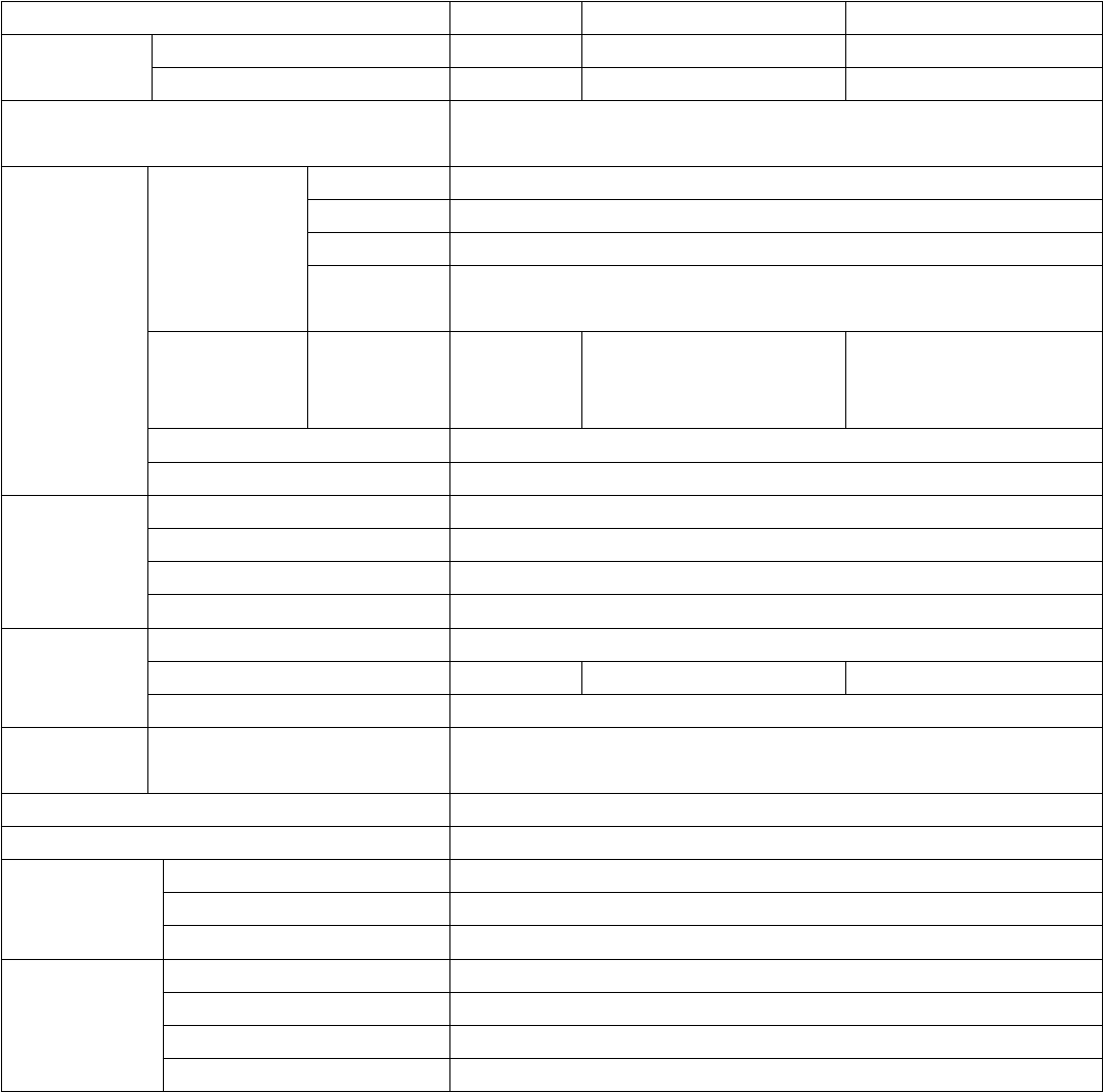
LCD KVM Console User Manual
57
Function
4口
8口
16 口
Connectors
Direct
4
8
16
Cascade(Max)
64
128
256
Port Selection
OSD Menu, Front Panel Hot-Key, Hot-key, Remote Control IP
(Optional)
Connectors
Console
Connectors
Video
17”\19”\19”Wide LED Screen
Keyboard
1 x USB Type A Female
Mouse
1 x USB Type A Female
Expansion
Port
1 x USB Type A Female(Prepositive port for keyboard,
mouse )
Computer
Port
Monitor、
Keyboard,
Mouse
4 x VGA
DB15bluef
emale
8 x VGA
DB15bluefemale
16 x VGA
DB15bluefemale
Power
1 x DC Jack
IP module network port
1 x RJ45
Toggle
Switch
Connection Port Selection
KVM operation panel Numeric buttons
KVM reset
KVM operation panel function buttons
IPModule reset
1 x Semi-embedded keys
IP Module restored initially
1 x Semi-embedded keys
LED
Indicator
light
Computer Select port
Two-digit LED display LED
Computer Online port
4 x red
8 x red
16 x red
IP module network port
1 x green 、1 x orange
Analog
Mode
Keyboard Mouse
USB、PS2
Maximum resolution video
1920 x 1200 @ 60HZLocal and remote
Scan time interval
3、5、10、15、20、30、40、60 seconds(default 3 seconds)
Operation
Environment
Operating temperature
0-50℃
Storage temperature
-20-60℃
Humidity
0-80%RH,No condensation
Machine
Attributes
Chassis
Metal
Single slide size
555 x 445 x 45mm
Dual slide size
645 x 443 x 45mm
Weight
16.6KG-18.1KG
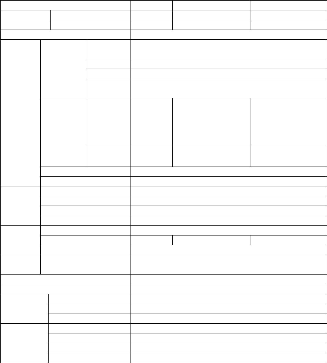
LCD KVM Console User Manual
57
CAT5 Series LCD KVM Switch Specification
Function
4口
8口
16 口
Computer
Connections
Direct
4
8
16
Cascade(Max)
64
128
256
Port Selection
OSD Menu, Buttons, Hot-key, Remote Control IP (Optional)
Connector
Console
Connectors
Video
17”\19”\19”wide-screen LCD Monitor
Keyboard
1 x USB Type A Female
Mouse
1 x USB Type A Female
Expansion
Port
1 x USB Type A Female( Prepositive USB port for keyboard,
mouse)
Computer
Connectors
Video
keyboard&
mouse
conversion
module
4 x USB
or 4 x PS2
8 x USB
or 8 x PS2
16 x USB
or16 x PS2
Conversion
module port
4 x RJ45
8 x RJ45
16 x RJ45
Power
1 x DC Jack
IP module network port
1 x RJ45
Toggle
switch
Connection Port Selection
KVM operation panel Numeric buttons
KVM reset
KVM operation panel function buttons
IP Module reset
1 x Semi-embedded keys
IP Module restored initially
1 x Semi-embedded keys
LED
Indicator
light
Computer Select port
Two-digit LED display LED
Computer Online port
4 x red
8 x red
16 x red
IP module network port
1 x green 、1 x orange
Analog
mode
Keyboard Mouse
USB、PS2
Maximum resolution video
1920 x 1200 @ 60HZ local & remote
Scan time interval
3、5、10、15、20、30、40、60 seconds(default 3 seconds)
Operation
Environment
Operating temperature
0-50℃
Storage temperature
-20-60℃
Humidity
0-80%RH,No condensation
Machine
Attributes
Chassis
Metal
Single slide size
555 x 445 x 45mm
Dual slide size
645 x 443 x 45 mm
Weight
16.6KG-18.1KG
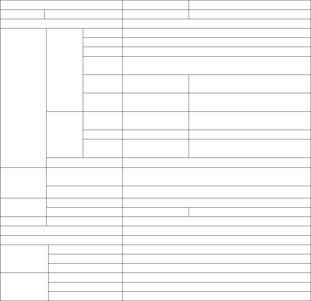
LCD KVM Console User Manual
57
DVI Series LCD KVM Switch Specification
Function
4口
8口
Connectors
Direct
4
8
Port Selection
OSD Menu, Buttons, hot keys
Connectors
Console
Port
Monitor
17”\19”\19”Wide-Screen LCD Monitor
Keyboard
1 x USB Type A female
Mouse
1 x USB Type A female
Expansion
Port
1 x USB Type A Famale (Prepositive port for Keyboard, mouse)
Microphon
e
4 x Mini Stereo
Female(Pink)
8 x Mini Stereo Female(Pink)
Audio
speakers
4 x Mini Stereo
Female(green)
8 x Mini Stereo Female(green)
Computer
Port
Keyboard,
Mouse
4 x USB Type B
Female
8 x USB Type B
Female
Video
4 x DVI-I
8 x DVI-I
Mixed
audio port
4 x Mini Stereo
Female(black)
8 x Mini Stereo
Female(black)
Power
1 x DC jack
Toggle switch
Connection Port
Selection
KVM operation panel Numeric buttons
KVM reset
KVM operation panel function buttons
LED
Indicator light
Computer Select port
Two-digit LED display LED
Computer Online port
4 x red
8 x red
Analog mode
Keyboard, Mouse
USB Type A
Maximum resolution video
1920 x 1200 @ 60HZ Local
Scan time interval
3、5、10、15、20、30、40、60seconds(default 3 seconds)
Operation
Environment
Operating temperature
0-50℃
Storage temperature
-20-60℃
Humidity
0-80%RH,No condensation
Machine
Attributes
Chassis
Metal
Size
555 x 445 x 45mm
Weight
16.6KG-18.1KG
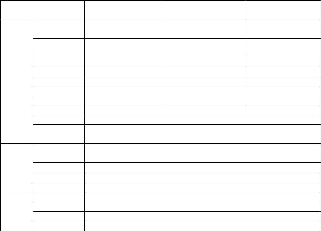
LCD KVM Console User Manual
57
LCD Module Specifications
Function
17inchLCD module
19inchLCD module
19inchwide-screen LCD
module
LCD
Display
Assembly
LCD Screen Size
Ratio
17inch4:3
19inch4:3
19inch16:9
LCD Screen
Type
SXGA TFT-LCD
Wide AHVA TFT-LCD
Viewing Area
337.920(H) × 270.336(V)
376.32 (H) x 301.056 (V)
408.96(H) x 230.04(V)
Resolution
1280*1024@60HZ
1980*1080@60HZ
Support color
16.7M color(RGB 6 bit + Hi_FRC)
16.7Mcolor,True 8 bit
Contrast
1000 : 1 (Typ)
Backlight
LED
Pixel spacing
0.264x0.297mm
0.294x0.294mm
300*300um
LEDService life
100,000Hours
Nominal Input
Voltage
+5.0V
Keyboard
Keyboard Layout
Ultra-thin US100 key,Stand alone Removable keyboard. (Keyboard language format
optional)
Compatible
Microsoft Windows9、Me/NT/2000/XP、WIN7、Server2003、WIN8、WIN10
Port
Standard PS/2;USB (Chocolate keyboard)
Service life
>1,000,000 times
Mouse
Mouse Type
Touch Mouse
Port
Standard PS/2
X/Y resolution
〉1000 point/inch,(40x40/mm)
Service life
>1,000,000 times

LCD KVM Console User Manual
57
Warranty Conditions
The Company shall not be liable for damages up to the amount paid by the Customer for the Products. In
addition, the Company does not assume any direct, indirect, special, incidental or consequential damages
resulting from the use of this product or the enclosed CD-ROM, documentation, etc…; The Company makes
no warranty, express, implied or statutory, regarding the content and use of this document and specifically
disclaims any implied warranties of merchantability, fitness for a particular purpose, suitability or fitness for
a particular purpose.