265XP Operator And Parts Manual
2016-03-25
: Sweepscrub 265Xp Parts And Operator Manual 265XP_Parts_and_operator_manual 1242 file product_file
Open the PDF directly: View PDF ![]() .
.
Page Count: 43
Automatic Floor Scrubber
265XP
Model No.:
608338
608339 - Pac
609246 - Can. Pac
Operator and Parts Manual
608370
Rev. 02 (12-02)
CUSTOMER SERVICE: 1-800-365-6625
FAX: 1- 800- 678- 4240
NOBLES
12875 RANSOM STREET
HOLLAND MI 49424 U.S.A.

OPERATION
2265XP (03- 99)
This manual is furnished with each new model. It
provides necessary operation and machine
maintenance instructions.
Read this manual completely and understand the
machine before operating or servicing it.
This machine will provide excellent service. However,
the best results will be obtained at minimum costs if:
SThe machine is operated with reasonable care.
SThe machine is maintained regularly - per the
machinecareinstructionsprovided.
SThe machine is maintained with supplied or
equivalent parts.
MACHINE DATA
Please fill out at time of installation for future reference.
Model No.- Install. Date - / /
Serial No.-
E2000 Tennant Company Printed in U.S.A.
Nobles is a registered United States trademark of Tennant Company
TABLE OF CONTENTS
SAFETY PRECAUTIONS 3......................
CONTROLS AND INSTRUMENTS 5..............
OPERATOR RESPONSIBILITY 6.................
RECEIPT OF MACHINE 6.......................
BATTERY INSTALLATION 6, 41..................
BRUSH AND PAD DRIVER INSTALLATION 6......
SQUEEGEE TOOL INSTALLATION 7.............
FILLING THE SOLUTION TANK 7................
MACHINE OPERATION 7........................
EStSwitch (Option) 8........................
CLEANING WITH THE MACHINE 8............
OPERATING TIPS 8.........................
EMPTYING THE TANKS 9.......................
SQUEEGEE ADJUSTMENTS 9..................
SQUEEGEE BLADE REPLACEMENT 10..........
OTHER USES FOR THE MACHINE 10............
ROUTINE MAINTENANCE 11....................
MAINTENANCE CHART 11...................
DAILY MAINTENANCE 12....................
BEFORE EACH USE 12...................
AFTER EACH USE 12.....................
BATTERY MAINTENANCE 12..............
CHARGING THE BATTERIES 13...........
WEEKLY MAINTENANCE 13..................
MONTHLY MAINTENANCE 13................
QUARTERLY MAINTENANCE 14..............
OPTIONAL KITS AND ATTACHMENTS 14.........
TROUBLE SHOOTING 15.......................
SPECIFICATIONS 17...........................
STANDARD PARTS 18..........................
Drive Carriage Assembly 18...................
Machine Frame (Front) 20.....................
Machine Frame (Rear) 22.....................
Scrubber Head Assembly 24...................
Scrubber Head Mounting 26...................
Squeegee Assembly 27.......................
Squeegee Arm Assembly 28...................
Control Console Assembly 30..................
Tank Assembly 32............................
Electrical Panel 34............................
Electrical Panel (cont’d.) 36....................
Battery Group 37.............................
BREAKDOWNS 38..............................
Pad Motor & Drive Motor 38...................
OPTIONS 39...................................
Wall Roller Kit 39.............................
EStOption Components 40...................
ELECTRICAL DIAGRAMS 42....................
Wiring Diagram 42
............................
Ladder Diagram 43...........................

OPERATION
3
265XP (03- 99)
SAFETY PRECAUTIONS
This machine is intended for industrial and
commercial use. It is suited to scrub hard floors in an
indoor environment and is not constructed for any
other use. Use only recommended pads, brushes and
cleaning detergents.
The following safety alert symbols are used
throughout this manual as indicated in their
description.
WARNING: To warn of hazards or unsafe
practices which could result in severe personal
injury or death.
FOR SAFETY: To identify actions which must be
followed for safe operation of equipment.
The following information signals potentially
dangerous conditions to the operator or equipment:
FOR SAFETY:
1. Do not operate machine:
- Unless trained and authorized.
- Unless operation manual is read and
understood.
- In flammable or explosive areas unless
designed for use in those areas.
2. Before starting machine:
- Make sure all safety devices are in place
and operate properly.
3. When using machine:
- Go slow on inclines and slippery
surfaces.
- Use care when reversing machine.
- Always follow safety and traffic rules.
- Report machine damage or faulty
operation immediately.
4. Before leaving or servicing machine:
- Stop on level surface.
- Turn off machine.
5. When servicing machine:
- Avoid moving parts. Do not wear loose
jackets, shirts, or sleeves.
- Block machine tires before jacking
machine up.
- Use hoist or jack of adequate capacity to
lift machine.
- Disconnect battery connections before
working on machine.
- Wear protective gloves when handling
batteries or battery cables.
- Avoid contact with battery acid.
- Use manufacturer supplied or approved
replacement parts.
WARNING: Batteries emit hydrogen gas.
Explosion or fire can result. Keep sparks and
open flame away. Keep battery compartment open
when charging.
WARNING: Flammable materials can cause
an explosion or fire. Do not use flammable
materials in tank(s).
WARNING: Flammable materials or reactive
metals can cause explosion or fire. Do not pick
up.
WARNING: Moving parts. Turn off power
before working on machine.
IMPORTANT NOTICE TO OWNERS:
The foam filled tire option must be installed in place of
the solid tires when the machine is used consistently
on grouted tile floors to prevent tile damage and
excessive machine component wear. Foam filled tires
should also be used on soft surfaces such as sports
floors to reduce wheel marking of surface.
ATTENTION: Usage of solid tires in the above
conditions will void the warranty on drive system
components.
OPERATION
4265XP (03- 99)
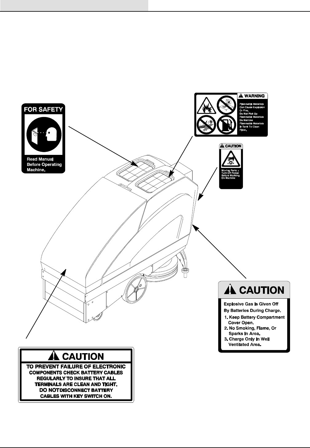
The following safety labels are mounted on the
machine in the locations indicated. If these or any
label become damaged or illegible, install new labels
in their place.
FOR SAFETY LABEL -
LOCATED ON THE LID OF
THE RECOVERY TANK.
FLAMMABLE SPILLS LABEL -
LOCATED ON THE LID OF THE
SOLUTION TANK.
MOVING PARTS LABEL
- LOCATED ON THE
REAR PANEL.
BATTERY GAS DECAL -
LOCATED ON THE
REAR PANEL
BATTERY CABLE DECAL -
LOCATED UNDER HOOD IN
FRONT
OF
BA
TTER
Y
TRA
YS
OPERATION
5
265XP (03- 99)
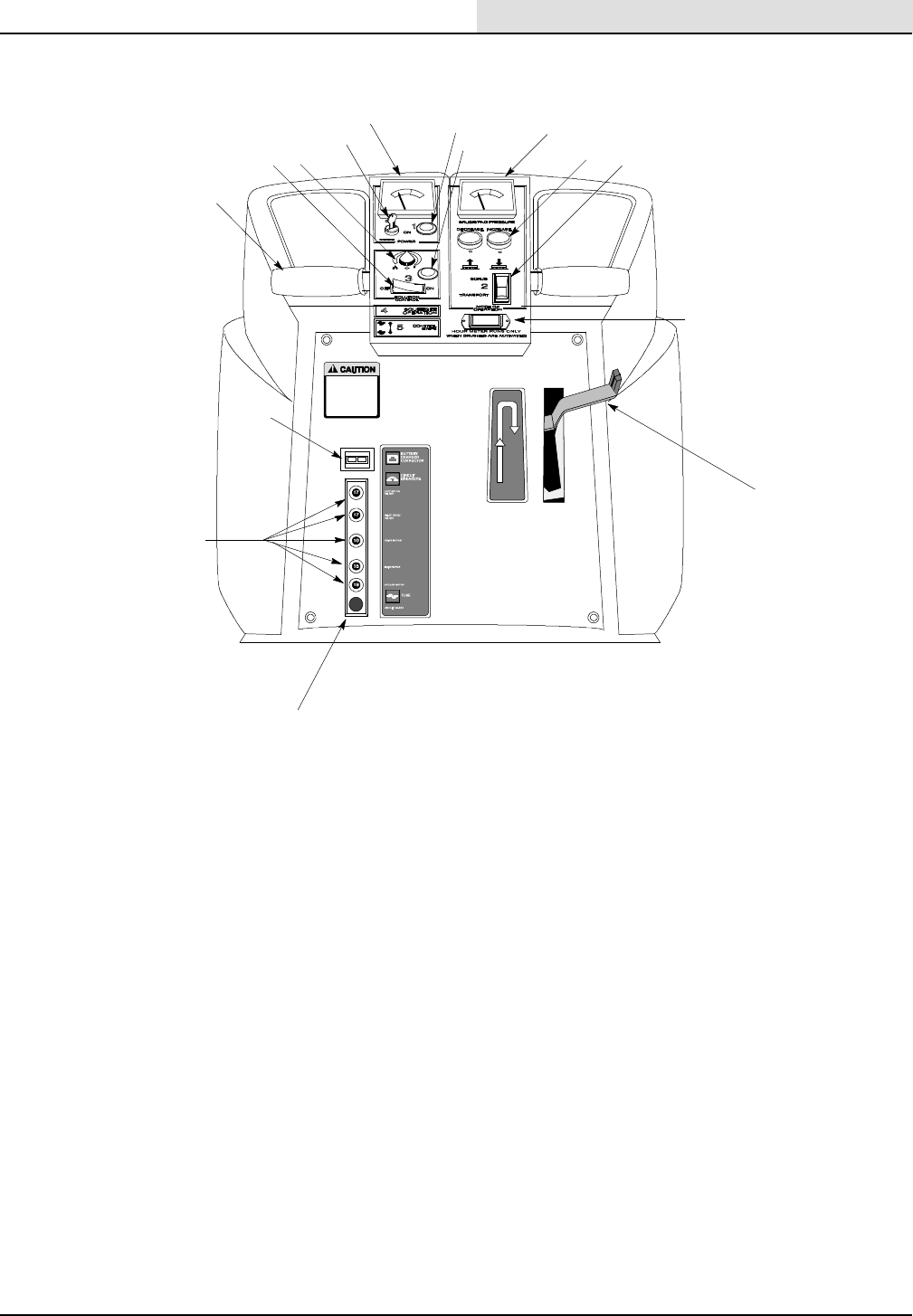
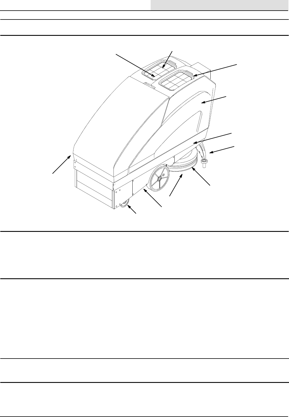
CONTROLS AND INSTRUMENTS
EF
GH
IJ
K
L
M
BC
D
A
N
O
A. Steering Handles
B. Solution Flow On/Off Switch
C. Solution Flow Control Knob
D. Key Switch
E. Battery Meter
F. On/Off Pilot Light (Green)
G. Solution Pilot Light (Blue)
H. Pad Pressure Meter
I. Brush Pressure Switch (Up/Down)
J. Brush Switch
K. Hour Meter
L. Squeegee Lift Handle
M. Fuse
N. Circuit Breakers
O. Battery Charger Connector
OPERATION
6265XP (03- 99)
OPERATOR RESPONSIBILITY
The operator’s responsibility is to take care of the
daily maintenance and checkups of the machine to
keep it in good working condition. The operator must
inform the service mechanic or supervisor when the
maintenance intervals are required as stated in the
MAINTENANCE section of this manual.
Read this manual carefully before operating this
machine.
FOR SAFETY: Do not operate machine unless
operation manual is read and understood.
After the first 50 hours (3 weeks) of operation the
following procedures are recommended:
SCheck the squeegee deflection.
SCheck the battery electrolyte level.
SCheck the battery cable connections.
RECEIPT OF MACHINE
Carefully check carton and machine for signs of
damage. If damaged, file claim with carrier
immediately. Concealed damage claims should be
filed within 90 days of receipt. Retain all packing
materials and delivery receipts for claim support.
BATTERY INSTALLATION
Battery installation must be completed before
removing machine from pallet. After batteries are
installed remove shipping screws (4) that mount front
and rear of machine to pallet. Create a ramp and
carefully push machine off pallet. Be certain that
scrub head is in the up position. See page 41 for
battery installation instructions.
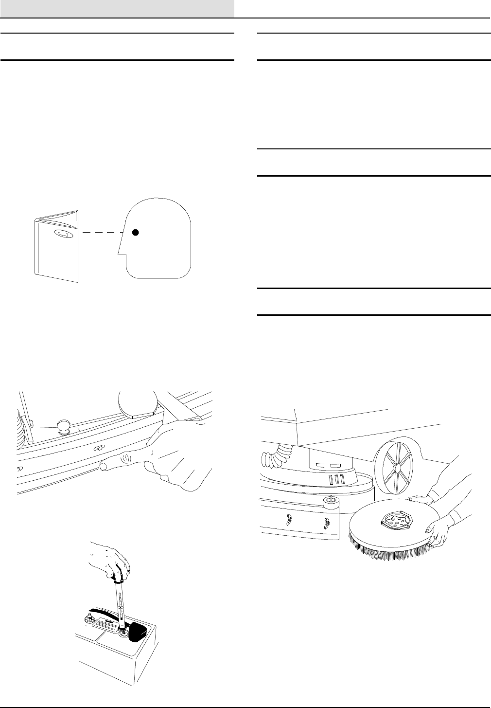
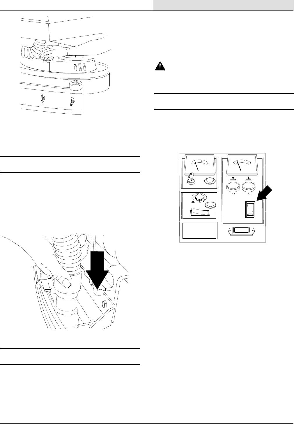
BRUSH AND PAD DRIVER INSTALLATION
1. Make sure the scrubber head is in the ”UP”
position, and the key switch is turned ”OFF.”
2. Slide the brush or pad driver under the scrubber
head. Holding the brush or pad driver with both
hands, lift it up to the drive hub and snap into
position (Figure 1).
FIG. 1.
NOTE: Pads should be mounted to drivers before
installation, for proper centering.
3. To remove the brush or pad driver, push down on
the brush release pin, located on the scrubber
head, behind each scrub motor (Figure 2).
OPERATION
7
265XP (03- 99)
FIG. 2.
ATTENTION: Do not operate scrub motors
without brushes or pad drivers (with pads) in
place.
SQUEEGEE TOOL INSTALLATION
Slide the squeegee tool onto the bracket, with the
wing screws loose. MAKE SURE the washers are on
top of the bracket. Tighten the wing screws (HAND
TIGHTEN ONLY). If they are too tight, this will defeat
the breakaway feature should the tool get caught on
an obstruction during use. Attach the pickup hose to
the tool (Figure 3).
FIG. 3.
FILLING THE SOLUTION TANK
Tanks on the machine are made of polyethylene and
are resistant to most cleaning solutions. CAUTION:
DO NOT USE WATER IN EXCESS OF 66°C
(150°F), as it can cause the material to become brittle
and void the warranty.
Remove the clear lid from the solution tank
(operator’s left) and pour solution to the fill line
located inside the tank. If powdered chemicals are
being used, mix the chemical with water before
putting it in the tank. This will help prevent clogging of
plumbing, valves, etc.
WARNING: Flammable materials can cause
an explosion or fire. Do not use flammable
materials in tank(s).
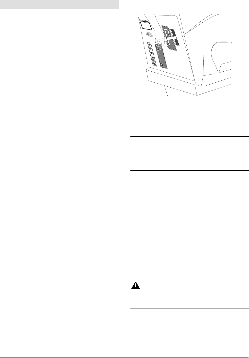
MACHINE OPERATION
1. Turn the ignition key to the ”ON” position.
2. Activate Scrub/Transport Switch to either
transport (brush- up) or scrub (brush down)
position (Figure 4).
FIG. 4.
To Transport:
SPress bottom half of Scrub/Transport Switch to
raise brush if you wish to transport the machine
without scrubbing.
STo travel, twist the control grips forward. As you
twist farther, the machine will travel faster.
STo stop, simply release the grips.
SFor reverse travel, twist the grips backward.
Reverse travel speed is limited for safety.
To Scrub:
SPress and release the top half of Scrub/Transport
Switch to lower brushes for scrubbing. The scrub
head will lower to the floor and automatically select
a pre- determined pressure, approximately 75 lbs.
This setting is sufficient for most applications. If this
pressure is right for your job, no additional operator
settings are required.
OPERATION
8265XP (03- 99)
To begin scrubbing, simply twist the handle grips
forward. The machine will begin to move forward and
the brushes will start spinning. Brushes will stop
approximately 2 seconds after the grips are released.
NOTE: While scrubbing, check the needle position of
the brush pressure meter. For normal scrubbing, the
indicator should be in the MIDDLE to LOWER green
section, as selected by the machine.
ATTENTION: Do not operate with the needle in
the RED zone. This will cause the circuit breakers
to trip.
If necessary, pad pressure can be adjusted using the
increase (+) and decrease (- ) buttons located on the
control console. Press the increase (if pressure is too
low) or decrease (if pressure is too high) button until
desired pressure is achieved.
SWhile scrubbing, check the needle position of the
brush pressure meter. For normal scrubbing, the
indicator should be in the MIDDLE to LOWER
green section.
To increase (+) or decrease (- ) pad pressure.
Press and hold brush switch until desired pressure
is achieved.
3. Check skirt for proper adjustment. To adjust the
skirt on the scrub head, loosen the latch located
on the rear of the scrub head. Push the skirt
evenly to the floor, and fasten the latch, securing
the skirt’s position. During operations where the
squeegee is off the floor, such as double scrub or
strip, be sure the skirt is positioned slightly off of
the floor to avoid ”plowing” solution.
4. To activate solution flow to pads or brushes
during scrub operation, press solution switch to
the ON position.
Solution flow can be regulated by turning the flow
adjustment knob toward the minimum or
maximum positions.
5. To lower the squeegee, lift the handle while
pressing to the right, then lower to the floor. The
vacuum motor will start when the handle is placed
in the lowest position (Figure 5).
FIG. 5.
6. To begin scrubbing, slowly twist the handle control
grips in the direction of desired travel. The scrub
motors will only start if they are in lowered
position.
EStSwitch (Option)
The EStswitch turns on and off the solution
recycling system.
CLEANING WITH THE MACHINE
Remove any potential obstructions to the brushes or
squeegee by sweeping the area to be cleaned prior to
operating the machine.
When operating the machine, work at a pace that
delivers the cleaning performance desired, and is safe
for the area being cleaned. Always operate at a
slower speed when working around walls or
obstacles. When turning, reduce speed to a lower
level to maintain maximum control.
The machine’s unique squeegee system
encompasses the brushes, therefore it is not
necessary to turn off the solution flow when making
turns. This squeegee system also enables you to
travel in reverse without lifting the squeegee off of
the floor.
WARNING: Flammable materials or reactive
metals can cause explosion or fire. Do not pick
up.
OPERATING TIPS
Do not park the machine for long periods of time on
resilient floors. The weight of the machine can leave
marks on the floor.
OPERATION
9
265XP (03- 99)
FOR SAFETY: Before leaving or servicing
machine, stop on level surface and turn off
machine.
If your machine is equipped with foam filled tires,
strong cleaning solutions will cause the tire to ”bleed”
on the floor. This is normal due to the mold release
compound used in making the tires, and it should
cease after a few weeks of use.
The harder you work the machine (heavy brush
pressure, etc.) the shorter your run time will be. Only
use as much power as is required for the job.
EMPTYING THE TANKS
The solution tank is designed to retain your unused
cleaning solution for reuse and savings. It does not
require draining after use. Should you choose to
drain, however, open the drain hose compartment
door located in the lower front area of the machine.
Pull out the clear drain hose (smaller diameter).
Remove the plug and drain the tank (Figure 6).
FOR SAFETY: Before leaving or servicing
machine, stop on level surface and turn off
machine.
FIG. 6.
The recovery tank is equipped with an automatic float
shut- off, which responds to the presence of water or
foam. When the tank is filled to it’s usable capacity,
the float will activate, shutting off the vacuum air flow.
The operator will notice an increase in the vacuum
motor sound level and a drop in vacuum pickup.
When this happens, raise the brushes and squeegee
tool and transport the machine to a disposal site.
Open the drain hose compartment door and pull the
(large) hose from the cavity. Remove the plug and
drain the tank. The volume of solution in the tank may
cause a rush of solution from the hose. Should the
operator desire to control this rush, turn the key on
and lower the squeegee to the floor. The vacuum will
hold the water in the tank (Figure 6).
The recovery tank should be flushed with clear water
under pressure after each use to prevent a building
up of heavy debris.
SQUEEGEE ADJUSTMENTS
To operate properly, the squeegee tool must be
properly adjusted. The squeegee tip adjustment
keeps the tool level to the floor, and the blade wiping
evenly from tip to tip. To adjust, lower the tool to the
floor and drive the machine slightly forward, until the
wiping blade lays over. Turn the knob to the right or
left to get proper blade deflection at the tips.
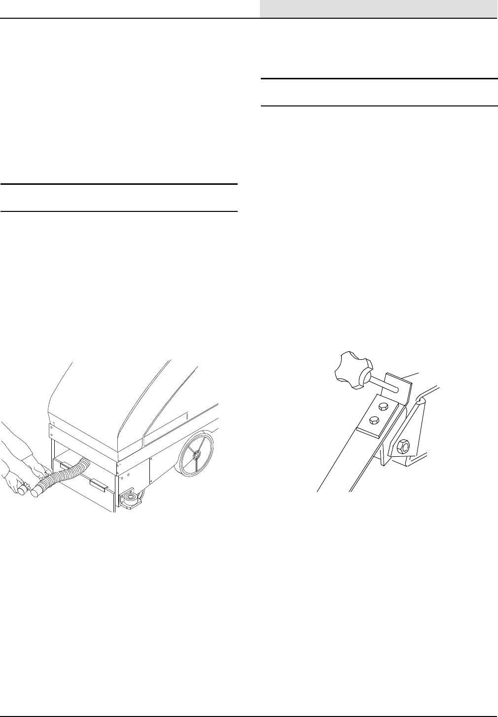
The squeegee pressure adjustment assures the
blade ”lays over” slightly in use and the sharp edge of
the blade wipes the floor. To adjust, lower the tool to
the floor and drive the machine ahead slightly. Locate
the adjustment knob at the top of the pressure arm
under the back of the machine. To increase pressure,
turn the knob clockwise; to decrease pressure, turn
counter- clockwise. Do not apply too much pressure,
only enough to lay the blade over, so the sharp edge
wipes the floor (Figure 7).
FIG. 7.
OPERATION
10 265XP (03- 99)
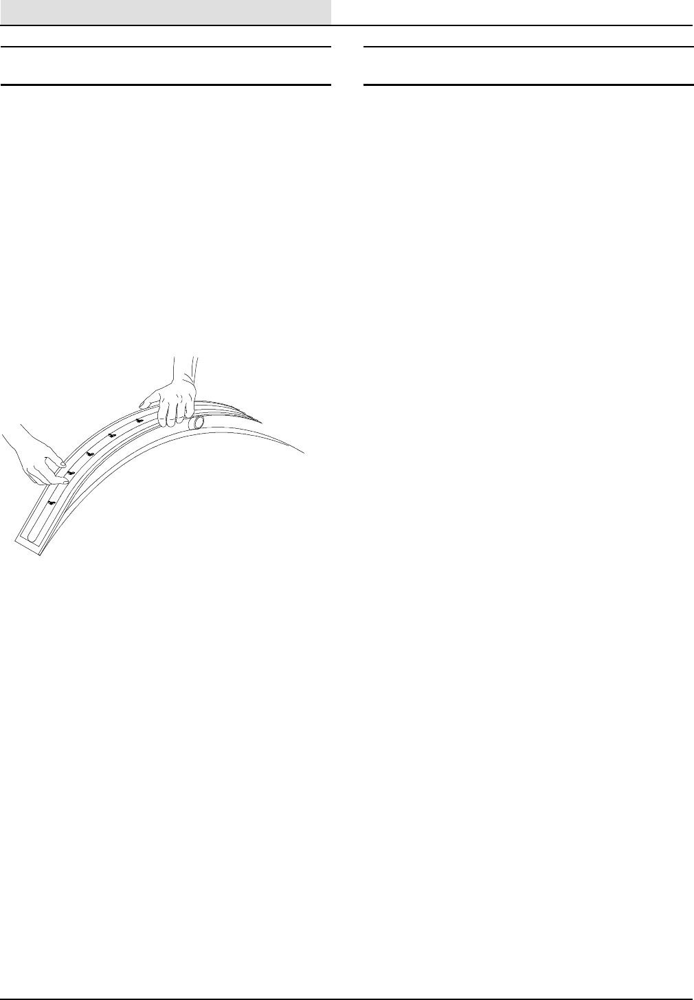
SQUEEGEE BLADE REPLACEMENT
Once the wiping edge has worn round, the blade will
no longer wipe the floor dry. The wiping blade has
four (4) usable edges. Once they are all used, a new
replacement blade kit should be installed, not just the
wiping blades. To reverse or replace the blades,
remove the tool from the machine. Starting at the
outside of each end of the tool, remove the bolts
toward the center. To install new blades, put all blades
in place, and install the bolts from the center out.
IMPORTANT: Proper blade installation is critical
to maximize water pick up. Make sure blades are
straight. Do not over tighten bolts, as this will
cause the blades to wrinkle (Figure 8).
FIG. 8.
OTHER USES FOR THE MACHINE
High Volume Water Pick Up
For high volume, high performance water pick up in
circumstances such as floods:
1. Lower the squeegee and leave the brushes up.
2. You can vacuum water as fast as you can walk.
To Polish Floors
1. Install polish pads on the machine.
2. Leave the squeegee up and lower the scrub head
to the floor.
3. Polish without water to a high shine!
High Performance Wet Vac
1. Remove the hose from the squeegee tool.
2. Using a connector, such as a short length of
1- 1/2” OD PVC pipe, connect a 1- 1/2” vacuum
hose, wand, and desired pick up tool to the
machine.
3. Lower the squeegee handle.
4. You have a 27 gallon wet vac at your disposal!
OPERATION
11
265XP (03- 99)
ROUTINE MAINTENANCE
1
5
9
10
2
7
8
11
4
6
3
MAINTENANCE CHART
Interval Key Description Procedure
No. Of
Service
Points
Daily 2Squeegee Check for damage and wear 1
Check deflection 1
8 Scrub brush or pad Check for damage and wear 1
1 Recovery tank Clean 1
1 Recovery tank, EStmode* Clean EStfilter 1
3 Recovery tank float screen Clean 1
5 Solution tank, EStmode* Clean 1
6 Machine Check for leaks 1
7 Scrub head skirt Check adjustment 1
Check for damage and wear 1
80 Hours 4Front casters Lubricate 4
2 Squeegee Check leveling 1
11 Chain Lubricate 1
800 Hours 9Vacuum fan motor Check motor brushes 1
10 Scrub brush motor Check motor brushes 1
OPERATION
12 265XP (03- 99)
DAILY MAINTENANCE
BEFORE EACH USE
MAKE SURE THE CHARGER HAS TURNED ”OFF”
by assuring the needle on the charger is at ”0.”
Unplug the charger from the wall receptacle, then
disconnect the charge from the machine (Figure 9).
FIG. 9.
Check all battery cells for low water level. Add distilled
water to just below the fill ring, if needed. Replace
caps. Wipe off the tops of batteries with a clean cloth.
FOR SAFETY: When servicing machine, avoid
contact with battery acid.
WARNING: Batteries emit hydrogen gas.
Explosion or fire can result. Keep sparks and
open flame away. Keep battery compartment open
when charging.
Make sure brushes or pad drivers with pads are
installed on machine before using the machine in the
scrub mode.
AFTER EACH USE
Drain and flush the recovery tank with clean water.
Replace the drain plug on the hose and return the
hose to its storage compartment.
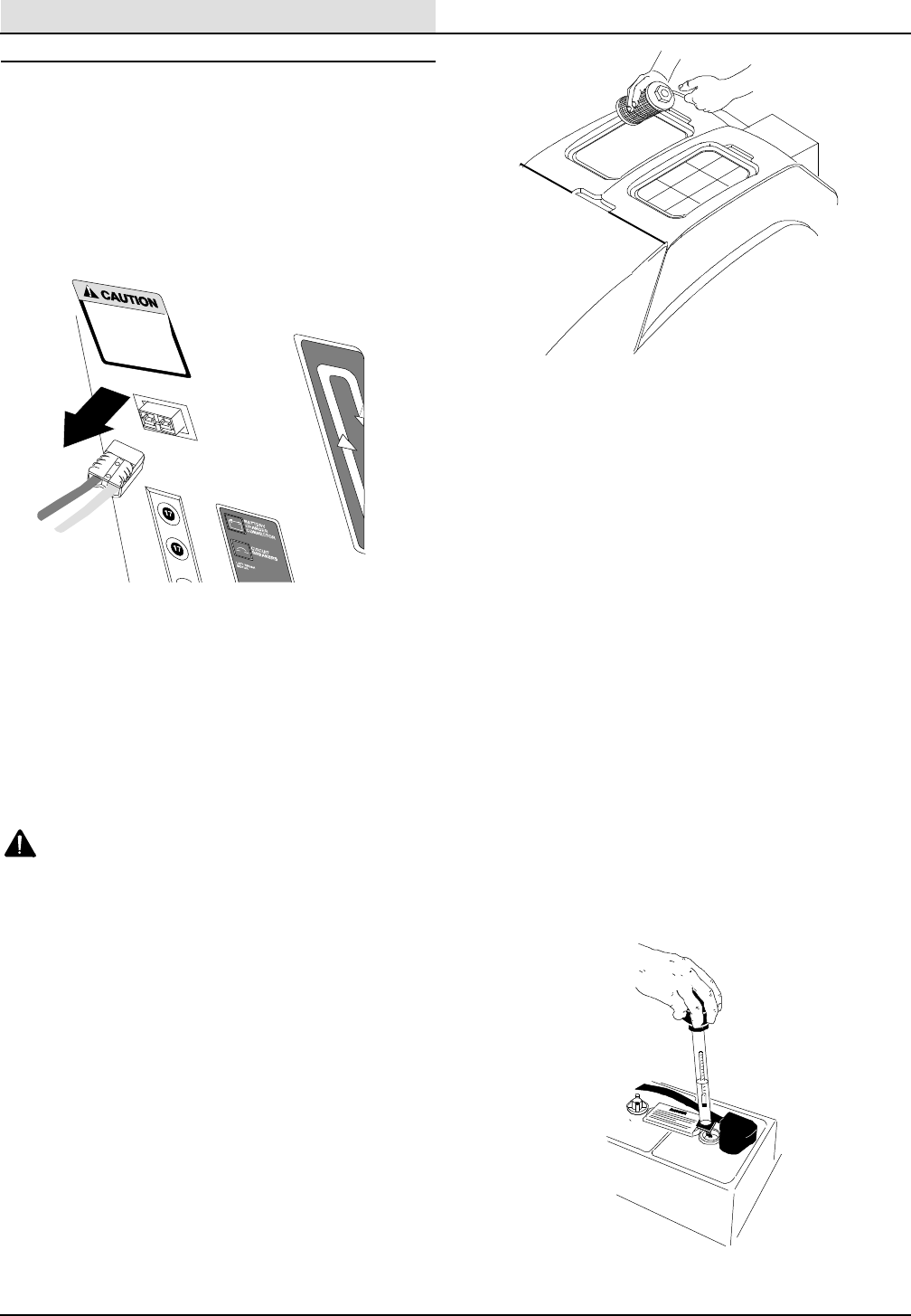
Remove the float shut- off assembly from the
recovery tank. The float shut- off easily pulls off, and
and pushes on its mounting plate. Rinse the float
shut- off and install on the machine (Figure 10).
FIG. 10.
Locate the recovery tank filter inside the tank, directly
below the float shut off. Unscrew and remove the
filter. Rinse off all debris from the filter screen and
install.
NOTE: NEVER REMOVE THE RECOVERY TANK
FILTER WITH SOLUTION IN THE TANK. Drain the
tank first, to avoid having debris enter the tank’s drain
passages.
Remove the brushes and squeegee tool from the
machine. Rinse under water. Inspect the brushes and
squeegee blades for wear; replace if required.
Reinstall on the machine.
Wipe down the entire machine with a damp cloth. A
light spray of Armor- AllRor a similar product will
keep the exterior looking like new!
BATTERY MAINTENANCE
Remove all battery caps and check the water level in
each cell. Add distilled water only to cover plates, or
a maximum or 1/4” below fill neck ring.
Never add acid to the batteries, only distilled water.
Always keep the battery caps on, except when adding
water or taking hydrometer readings (Figure 11).
FIG. 11.
OPERATION
13
265XP (03- 99)
CHARGING THE BATTERIES
1. Push the machine to a flat, dry surface in a well
ventilated area.
2. Turn the machine power off.
FOR SAFETY: Before leaving or servicing
machine, stop on a level surface and turn off
machine.
3. Lift the hood to access the battery compartment.
4. Check the water level in all battery cells. If the
level is low, add just enough distilled water to
cover the plates. DO NOT OVERFILL. The
batteries can overflow during charging due to
expansion.
FOR SAFETY: When servicing machine, avoid
contact with battery acid.
5. Plug the charger connector into the battery
connector.
WARNING: Batteries emit hydrogen gas.
Explosion or fire can result. Keep sparks and
open flame away. Keep battery compartment open
when charging.
6. Plug the battery charger into the wall outlet.
7. The charger will start automatically. Check the
charger meter to assure the charger is working.
When the batteries are fully charged, the charger
will automatically turn off.
8. After the charger has turned off, unplug the
charger from the wall outlet.
9. Unplug the charger connector from the battery
connector on the machine.
NOTE: Make sure the battery caps are in place while
charging.
NOTE: Do not take readings immediately after
adding distilled water. If the water and acid are not
thoroughly mixed, the readings may not be accurate.
Check the hydrometer readings against the following
chart to determine the remaining battery charge level:
Specific Gravity at
27°C(80°F)
Battery
Charge
1.265 100% Charged
1.223 75% Charged
1.185 50% Charged
1.148 25% Charged
1.110 Discharged
NOTE: If the readings are taken when the battery
electrolyte level is any temperature other than 27°C
(80°F), the reading must be temperature corrected.
Add or subtract to the specific reading 0.004 (4 point)
for each 6°C(10°F) above or below 27°C(80°F).
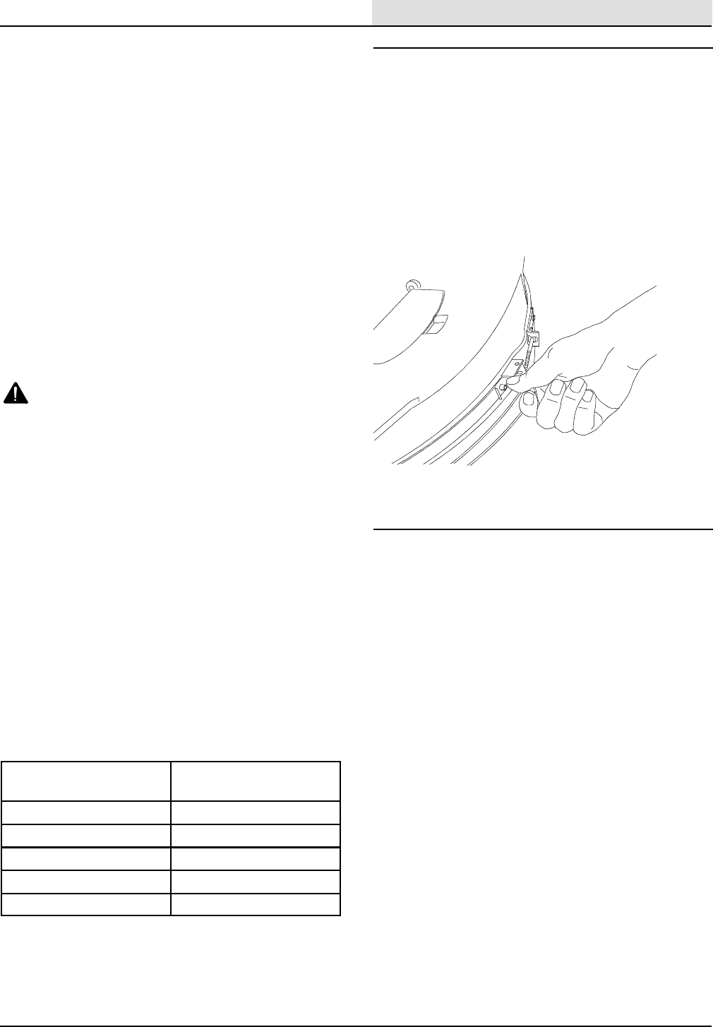
WEEKLY MAINTENANCE
Inspect the scrub head skirt for adjustment and wear.
For proper adjustment, the skirt should be resting on
the floor, with the brushes at the desired pressure. To
readjust, lower the scrubber head to the desired
pressure. Release the clamp on the skirt, and push
the skirt down until it rests on the floor all the way
around the casting. Tighten clamp. If the skirt is torn
or worn beyond adjustment, replace (Figure 12).
FIG. 12.
MONTHLY MAINTENANCE
SClean the top surface of the batteries and terminals,
and check for loose connections. Use a strong
solution of baking soda and water. Brush the solution
sparingly over the battery tops, terminals, and cable
clamps. DO NOT allow any solution to enter the
batteries. Use a wire brush to clean the terminal
posts and cable connectors. After cleaning, apply a
coating of clear battery post protector to the terminals
and cable connections. Keep the tops of the batteries
clean and dry.
Keep all metallic objects off the top of the batteries,
which may cause a short circuit. Replace any worn or
damaged wires.
SGrease the swivel zerk and the wheel zerk on each
front caster.
SLubricate the squeegee wing screws and the front
drain door hinge.
SInspect float and vacuum motor screen. Replace, if
required.
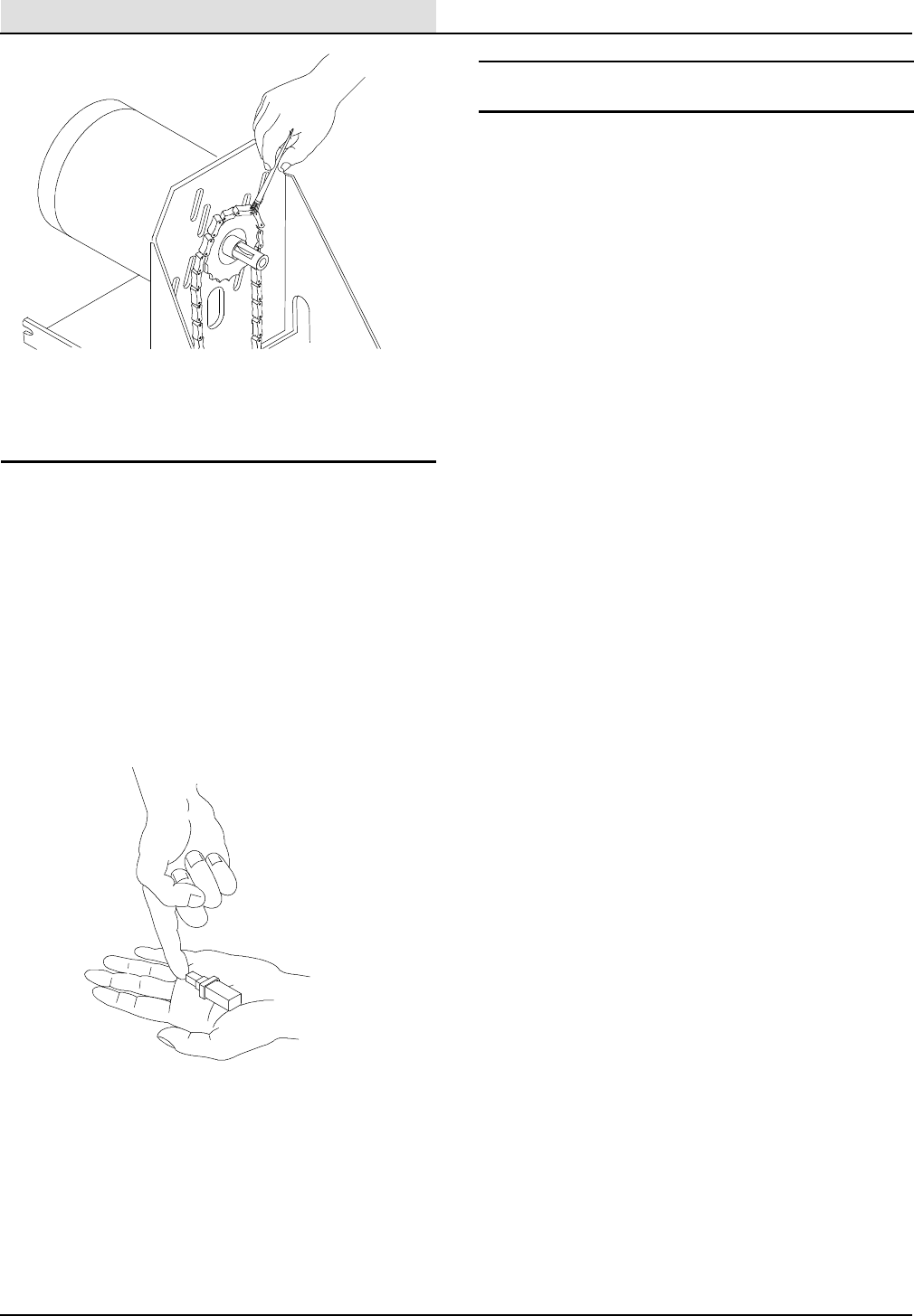
SGrease the drive chain. Adjust tension, if required
(Figure 13).
OPERATION
14 265XP (03- 99)
FIG. 13.
QUARTERLY MAINTENANCE
NOTE: It is recommended six month and annual
maintenance procedures be performed by technicians
from your authorized Service Center. Inspection,
adjustment, and lubrication are not warrantable items,
and thus may be performed by most qualified service
people. Ask your service center for a Planned
Maintenance Agreement, to assure your machine is in
top operating condition at all times!
Inspect the vacuum motor brushes. Replace if worn to
10 mm (0.38 in) or less (Figure 14).
FIG. 14.
Inspect the carbon motor brushes in both drive
motors, plus the traction drive motor. Replace if worn
to 10 mm (0.38 in) or less.
OPTIONAL KITS AND ATTACHMENTS
The following options are available, at an additional
cost, for field or factory installation.
FOAM FILLED TIRES
A softer tire used on rough or grouted tile floors, or
where extra traction is needed. Field installation is
available.
IMPORTANT: Foam filled tires are required if the
machine is used on grouted tile floors. Drive train
warranty will be void unless so equipped! See safety
instruction section of this manual for details.
HIGH BUMPER ROLLER KIT
Mounted on the front corners of the machine, to
protect the machine and fixtures. Field installation is
available.
POWER WAND ATTACHMENT
The optional power wand attachment has both
squeegee blades and a scrub brush for maximum
reach cleaning. Its low profile swivel head design
provides fast and effective cleaning under appliances
and fixtures. This is available as a field installed
option only.
ESt(Extended Scrub)
The EStoption package allows you to transform
your scrubber into a solution recycle machine simply
by flipping a switch. This is available as a field
installed option only.

OPERATION
15
265XP (03- 99)
TROUBLE SHOOTING
PROBLEM CAUSE SOLUTION
Machine does not operate. Key switch is off. Turn key to ”ON”.
Batteries discharged. Charge batteries.
Loose or corroded battery cables. Clean and lubricate.
Electrical malfunction. Contact Service Center for assis-
tance.
Machine does not self propel Key switch is off. Turn key to ”ON”.
Drive circuit breaker is tripped. Reset Breaker.
Drive chain is broken. Contact Service Center for assis-
tance.
Electrical malfunction. Contact Service Center for assis-
tance.
Circuit breaker for transport drive
trips.
Operator attempting to negotiate
grades in excess of machine capabil-
ities.
See safety instructions in this
manual for instructions.
Machine travel obstructed. Remove obstructions.
Operator using directional control
as a brake.
Cease using directional control as a
brake.
Caster or differential bearings are
dragging.
Contact Service Center for assis-
tance.
Work motor brushes. Contact Service Center for assis-
tance.
Poor solution flow. Solution tank filter is plugged. Remove and clean filter.
Min/Max control malfunction. Contact Service Center for assis-
tance.
Electrical malfunction. Contact Service Center for assis-
tance.
Brush motor(s) do not operate. Circuit breaker(s) tripped. Reset breaker(s), reduce pressure.
Scrub head not lowered. Lower head to floor.
Transport grips not activated Grips must be activated for brushes
to operate.
Circuit breakers on brush motor trip
.
Excessive brush pressure. Reduce pressure.
Improper brush or pad for opera-
tion.
Use correct, or less aggressive pad
based on application.
Dirty pads. Replace or clean.
Defective breaker(s). Contact Service Center for assis-
tance.
Worn motor brushes. Contact Service Center for assis-
tance.
Vacuum motor will not operate. Key switch to ”OFF”. Turn key to ”ON”.
Squeegee lift handle not lowered. Lower handle to lowest point.
Electrical malfunction. Contact Service Center for assis-
tance.

OPERATION
16 265XP (03- 99)
TROUBLE SHOOTING - continued
PROBLEM CAUSE SOLUTION
Poor vacuum pick up. Recovery tank lid not properly
sealed.
Insure float housing is in place and
locked.
Filter cage screen plugged. Clean.
Recovery tank drain hose left open. Replace cap.
Hole or leak in vacuum hose. Repair or replace.
Blockage in pick up hose or wand. Inspect hose and tool for blockage
and clean. Inspect recovery tank at
hose entrance for material pick up.
Low battery charge. Charge batteries.
Leak in recovery tank. Contact Service Center for assis-
tance.
Vac motor malfunction. Contact Service Center for assis-
tance.
Electrical malfunction. Contact Service Center for assis-
tance.
Squeegee streaks, uneven pick up. Squeegee obstructed. Check and clean tool and blades.
NOTE: Sweep floor before scrub-
bing.
Squeegee angle out of adjustment Adjust to proper angle
Improper squeegee pressure Adjust pressure
Squeegee blades worn Reverse or replace
Inadequate squeegee lubrication for
floor conditions
Increase solution flow
Blades installed improperly Refer to Squeegee Blade Installa-
tion Section of this manual
Batteries deliver below normal run
time.
Batteries not fully charged. Charge batteries.
Electrolyte level is low. Fill to proper level and charge (DIS-
TILLED WATER ONLY).
Cables are loose or corroded Clean and lubricate
Pad pressure too heavy Reduce pressure
Improper pads causing too much
amp draw
Change to proper pads
Charger is defective Contact Service Center for assis-
tance
Battery is defective Contact Service Center for assis-
tance

OPERATION
17
265XP (03- 99)
SPECIFICATIONS
GENERAL MACHINE DIMENSIONS/CAPACITIES
Item Dimension/Capacity
Overall length 1651 mm (65 in)
Width (less squeegee) 610 mm (27 in)
Height 1118 mm (43.5 in)
Scrub brush diameter 343 mm (13.5 in)
Squeegee width 800.1 mm (31.5 in)
Scrubbing path width 660 mm (26 in)
Solution tank capacity 94.6L (25 gal)
Recovery tank capacity 102.2L (27 gal)
Dry weight, less batteries 249Kg (549 lbs)
GENERAL MACHINE PERFORMANCE
Item Measure
Aisle turnaround width 1828.8 mm (72 in)
Maximum trailer loading clearance angle 8°
POWER TYPE
Type Quantity Volts Ah Rating Weight
Batteries 66235 @ 20 hr rate 29.9Kg (66 lbs) each
Type Use VDC Hp
Electric motors Scrub brush (2) 36 .45
Vacuum fan (1) 36 .75
Propelling (1) 36 .45
Type VDC Amp Hz Phase VAC
Chargers 36 25 60 1120
TIRES
Location Type Size
Front casters (2) Solid, non- marking urethane 11 x 2 inch
Rear Tires (2) Solid, non- marking urethane 5x2inch
STANDARD PARTS
265XP (03- 99)
18
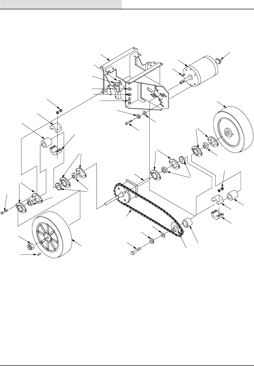
DriveCarriageAssembly
1
3
2
4
5
6
7
10
8
9
14
15
16
17
18
21
28
29
7
25
18
20
20
18
19
19
26
27
22
23
24
11
18
13
19
17
12
16
14
15

STANDARD PARTS
19
265XP (03- 99)
DriveCarriageAssembly
Ref. Part No. Description Qty.
1 611 015 000 Carriage Weldment 1
2 140506 Nut, Hex, Std., .31”- 18 8
3 140015 Washer, Lock, Spring 8
4 069 764 080 Key, 0.25” x 0.25” x 0.75” 1
5 069 762 427 Motor, Drive, .45 HP 1
6 575037 Clip, Cable 1
7 611 333 000 Wheel, 11” 2” Wide 2
8 140013 Washer, Plain, ANSI- A, .38”, ZP 4
9 069 760 088 Washer, Lock, Spg. 4
10 200 031 541 Screw, Hex Hd., M10 x 25 4
11 140016 Washer, Lock, Spring 4
12 069 760 108 Screw, Hex Head, 1/4- 20 UNC x .88” 4
13 069 760 082 Washer, Plain, ANSI- A, .25” Wide 4
14 611421 Screw, Socket Head, 1/4- 28 x .5” Long 8
15 611426 Collar, 4 Bolt (Through) 2
16 611410 Differential Spacer 2
17 611425 Collar, 4 Bolt, 1/4- 28 UNF 2
18 069 760 006 Bearing, Flangette, 2 Hole, Set Of 2 8
19 069 760 007 Bearing, Ball, 19.05 4
20 611 376 000 Differential, Sprocket 40 Tooth 1
21 069 762 137 Screw, Carriage, .31- 18 UNC x 1.00” 8
22 611 054 000 Chain, #41, 66 Links (33” Long) 1
23 14880.5 Washer, Flat 5/16” 1
24 140015 Washer, Split Lock 5/16” 1
25 069 760 107 Screw, Hex Head, .31- 18 UNC x .62” 1
26 069 760 741 Spacer, 19.9mm x 25.4mm x 18 mm 1
27 069 760 365 Sprocket, #41 Chain, 10 Tooth 1
28 612 074 000 Nut, Hex Lock, .75- 10 UNC 2
29 612 004 000 Key,Square, .188” x 1.50” Long 2
STANDARD PARTS
265XP (03- 99)
20
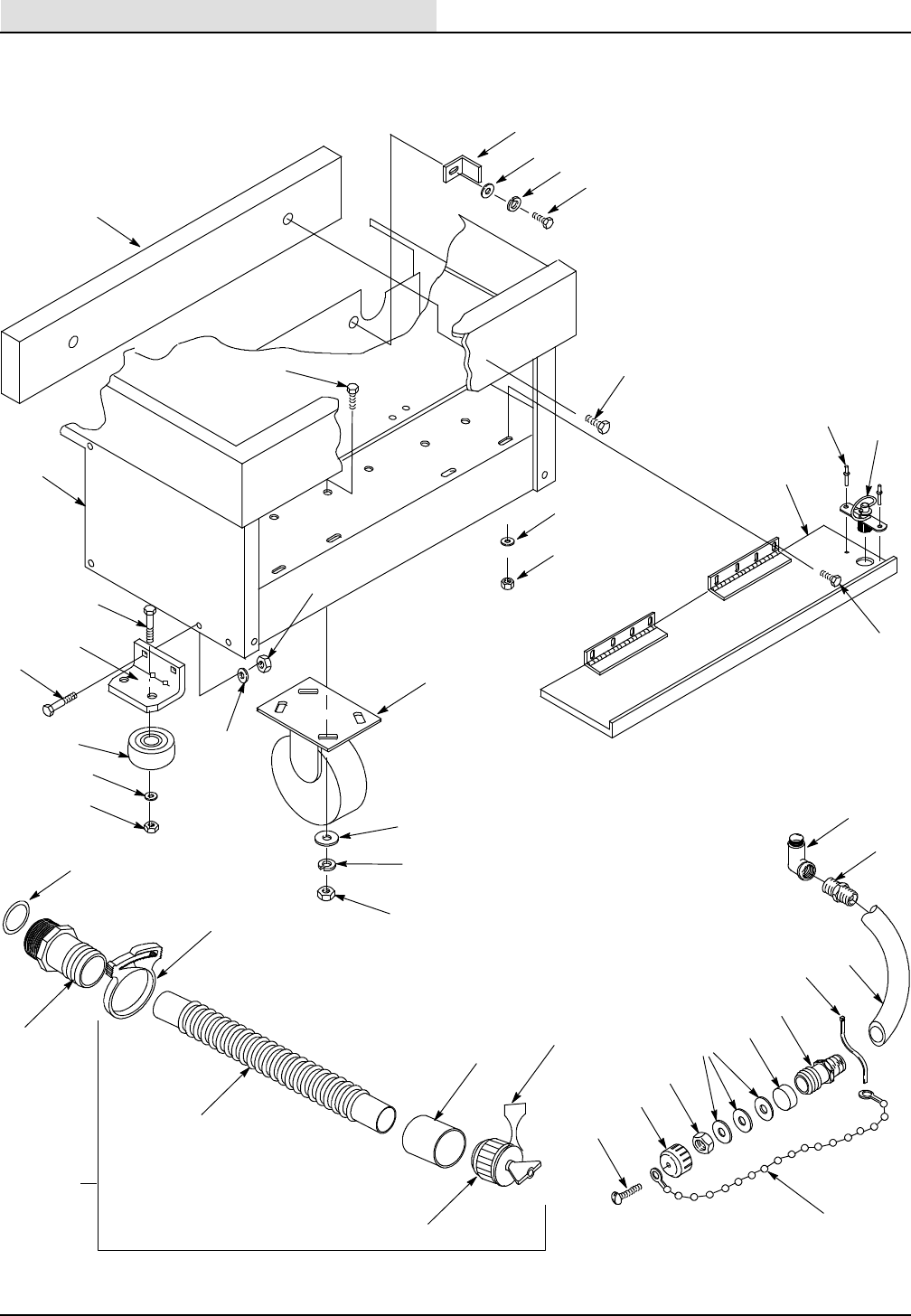
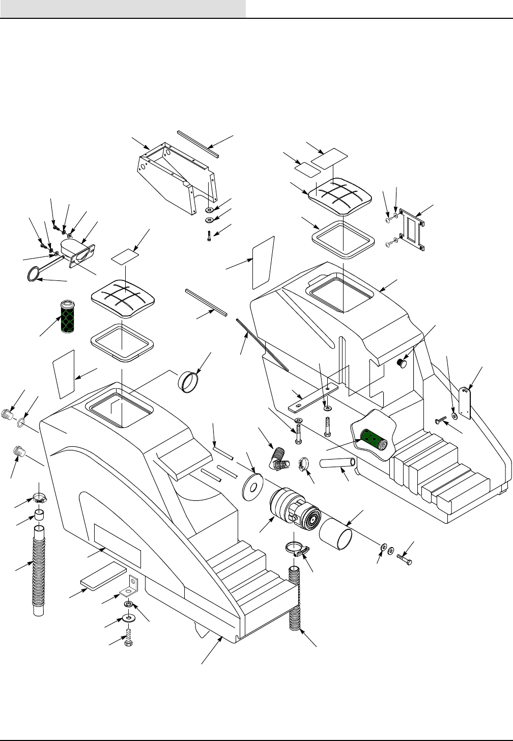
Machine Frame (Front)
1
2
3
4
14
15
16
19
20
21
5
8
22
24
25
18
17
9
7
31
39
36
38
30
29
28
26
23
35
33
32 37
40
34
11
12
10
13
6
27
41
42
43
44
45

STANDARD PARTS
21
265XP (03- 99)
Machine Frame (Front)
Ref. Part No. Description Qty.
1 626063 Counter Weight 1
2 626008 Frame Weldment 1
3 200 031 544 Screw, Hex Hd., M10 x 25 8
4 200 055 343 Screw, Pan Head Slot M04 x 12mm 1
5 069 764 060 Screw, Truss Hd., .31- 18 x .75” 2
6 621443 Chain, Drain Plug 1
7 130041 Tie, Wire 1
8 140031 Washer, Lock, Spring, ANSI, #10, ZP 4
9 579134 Nut, Hex, Std., #10- 24 UNC, Zinc Plate 4
10 601 092 000 Screw, Hex Hd., #10- 24 UNC x .5” 4
11 626044 Door, Front 1
12 140962 Latch 1
13 28681 Rivet 2
14 069 760 092 Screw, Hex Hd., .31- 18 UNC x 1.75” 2
15 611 053.BK Bracket, Wheel, Front 2
16 069 767 077 Screw, Carriage, .31- 18 UNC x .75” LG., ZP 4
17 140015 Washer, Split Lock 5/16” 4
18 140506 Nut, Hex 5/16”- 18 4
19 630450 Wheel, Rubber, 76 x 22 WD 2
20 069 760 082 Washer, Plain, ANSI- A, .25” Wide, ZP 2
21 140546 Nut, Lock Nylon Insert 5/16”- 18 2
22 069 760 030 Caster, 127 mm x 50 mm Wide 2
23 140036 Washer, Flat 3/8” 8
24 069 760 088 Washer, Lock, Spring, ANSI, .44” ZP, M10 8
25 140285 Nut, Hex Std., M10 x 1.50 8
26 626111 Fitting, Straight 1.50” Tube, 1.50”NPT 1
27 603217 Asm, Drainhose 1
Y28 140308 Clamp, Hose 1- 5/16 to 2- 1/4 1
Y29 630068 Hose, Drain 38.1 ID 1
Y30 630394 Sleeve, Drain Hose 1.5 ID Copper 1
Y31 621324 Plug, Expansion 1- 1/2” Dia 1
Y32 578441 Strap, Drain Hose 1
33 578 034 000 Fitting, Elbow 1”NPT 1
34 626079 Fitting, Reducer 1”M x 3/4” Barb 1
35 626093 Hose, Clear .75 ID 19” x 670mm 1
36 612 146 000 Fitting, Straight .75 Hose x .75 NPT 1
37 612 145 000 Seal, Solution Drain Cap 1
38 601 076 000 Washer, Flat Plastic 3
39 200 160 014 Nut, Hex Lock M04 1
40 612 158 000 Cap, .75” NPT Plastic w/Hole 1
41 606970 Bracket, Solution Hose 1
42 019680127 Washer, Flat 1
43 578244000 Washer, 6.4x10.0 lck ss 1
44 200031436 Screw m6 x 1 x 16 hxhdcp 1
45 607018 Spacer, Drainhose Fitting 1
= ASSEMBLY
Y= INCLUDED IN ASSEMBLY
STANDARD PARTS
265XP (03- 99)
22
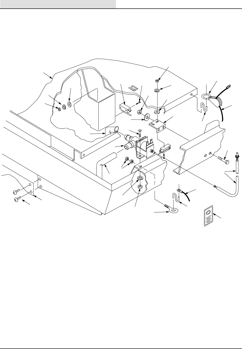
Machine Frame (Rear)
1
2
3
4
7
23
14
15
19
11
12
5
4
3
8
9
10
2
13
17
18
6
24
25
16
20
21
15
22
21

STANDARD PARTS
23
265XP (03- 99)
Machine Frame (Rear)
Ref. Part No. Description Qty.
1 626008 Frame, Weldment 1
2 140026 Washer, Plain, ANSI- A, #06, ZP 4
3 069 760 093 Washer, Lock, Spring, ANSI, #08, ZP 2
4 069 762 159 Nut, Hex, Std., #06- 32 UNC, ZP 4
5 069 764 009 Switch, Snap, 24A, Lever, SPNO & C 2
6 626120 Cable, Water Flow Control 1
7 626204 Hose, 320mm 1
8 069 764 002 Screw, Hex Head, #06- 32 UNC x 1.00 4
9 200 102 014 Nut, Hex, Std., M04 x 0.70 2
10 069 760 093 Washer, Lock, Spring, ANSI, #08, ZP 4
11 200 031 436 Screw, Hex Hd., M06 x 16 mm 2
12 626100 Valve, Liquid Dispensing 1
13 611 155 000 Switch Bracket, Actuator Linkage 1
14 069 762 361 Pulley, Block, 1- 1/2” 1
15 611 163 000 Hook, S, Squeegee Lift & Swivel Block 2
16 626205 Hose, 510mm 1
17 602 139 000 Washer, Flat, 6.4mm x 12.7mm x 1.7 1
18 579028 Nut, Hex Lock M06, ZP 1
19 200 031 342 Screw, Hex Hd., M04 x 10 1
20 578769 Decal, Caution Moving Parts 1
21 626073 Cable, Squeegee Lift 1
22 600205 Eye Bolt, 1/4” 1
23 069 760 094 Nut, Hex Jam .25- 20UNC 2
24 626055 Skirt, Lower 1
25 200 070 432 Screw, M06 x 10mm 4
STANDARD PARTS
265XP (03- 99)
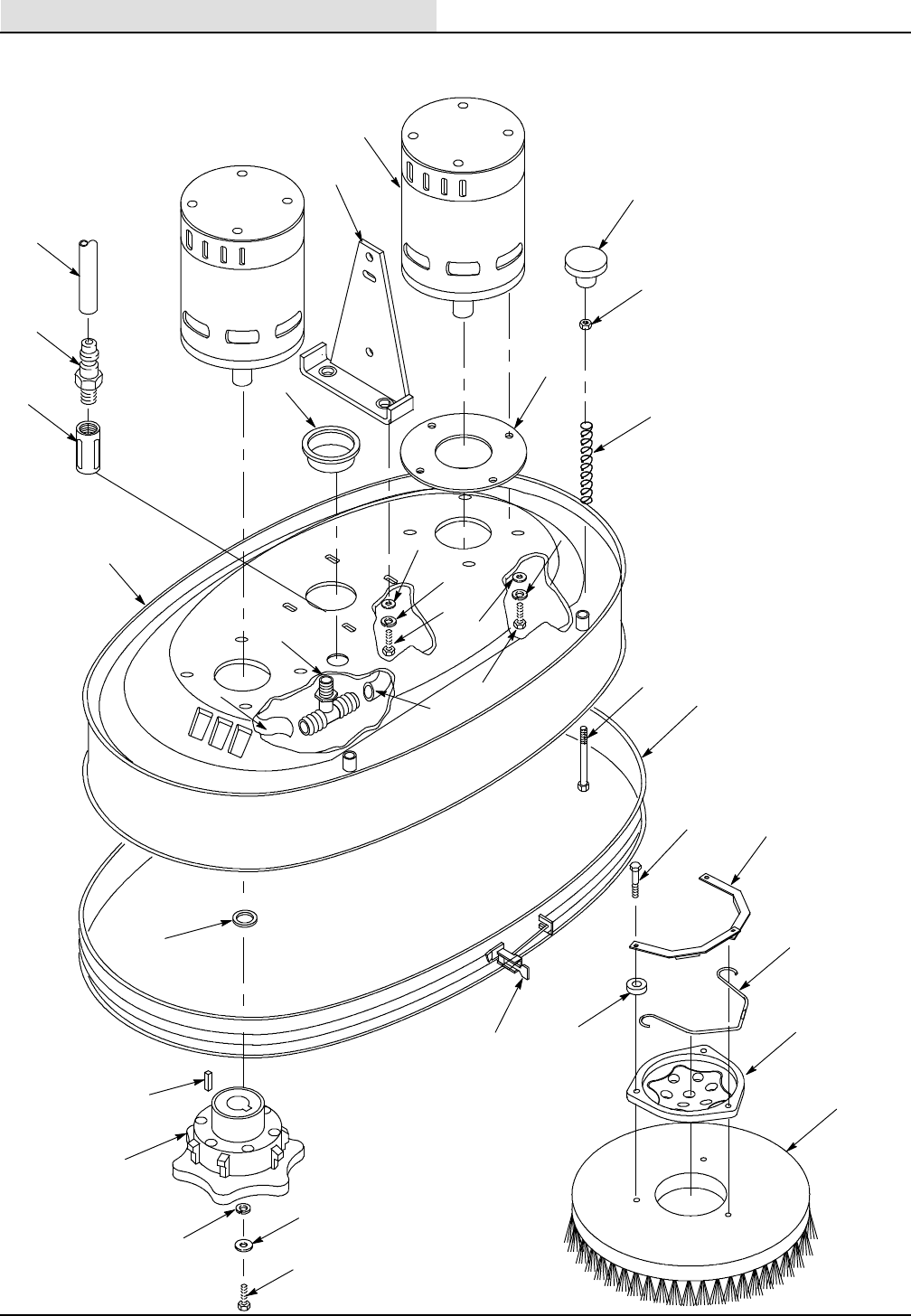
24
Scrubber Head Assembly
1
10 6
15
16 14
17
18
20
21
22
23
24
28
3
5
4
2
8
11
13
12
19
9
26
29
32
34
33
25
7
27
31
35
30

STANDARD PARTS
265XP (12- 02) 25
Scrubber Head Assembly
Ref. Part No. Description Qty.
1 069 762 427 Motor, Drive, .45 HP 2
2 612468 Gasket, End Bell 2
3 069 760 082 Washer, Plain, ANSI- A, .25” Wide, ZP 8
4 140016 Washer, Lock, Spring, ANSI, .25” Wide, ZP, M06 8
5 069 760 108 Screw, Hex Hd., 1/4- 20 UNC x .88”, SS 8
6 626083 Knob, 3/8- 16 2
7 039 708 223 Nut, Hex Jam, .38- 16 UNC 2
8 626081 Spring, Compression 2
9 590248 Screw, Hex Head, 3/8”- 16 x 4.75” Long 2
10 626084 Bracket, Head Lift 2
11 14880.5 Washer, Flat, ANSI- A, .31” Wide, ZP, M08 4
12 140015 Washer, Lock, Spring, ANSI, .31”, ZP, M06 8
13 200 607 491 Screw, Hex Hd., M08 x 25 mm 4
14 069 764 561 Caplug, 33- A1, 2.62” Hole/2.44” Tube 1
15 069 764 592 Fitting, 1/2”Hosex1/2”NPT 1
16 069 764 137 Fitting, Coupling, 1/2” NPT, PVC 1
17 069 760 729 Fitting, Tee, 1/2”Hosex1/2”NPT 1
18 069 760 725 Hose, Solution, 12.7 ID x 73.5mm 1
19 069 760 726 Hose, 12.7 ID x 225mm 1
20 611 108 000 Scrubber Head, Permold 1
21 626138 Spacer, 19.1 x 31.7 x 7.9 mm, ZP 2
22 140632 Key, 0.25” x 0.25” x 1.00” 2
23 626022 Hub, Brush 2
24 069 764 631 Washer, Flat, 8.4mm, 25.4, 4.8 4
25 140015 Washer, Lock, Spring, ANSI, .31”, ZP, M06 2
26 621 284 000 Screw, Hex Head, .31- 18 UNC x 1.25” ZP 2
27 626059 Skirt, Scrubber Head 1
28 626136 Band Assembly, Retaining 1
29 626174 Brush Assembly, Poly Setof2
626175 Brush Assembly, Nylon Setof2
626176 Brush Assembly, Grit Setof2
626071 Pad Driver Assembly Setof2
611 191 000 Drive Block, 260 Setof2
Y30 626133 Brush Adapter Setof2
Y31 630431 Screw, Hex Head, M6 x 40 6
Y32 21852 Clip, Brush Hub 4
Y33 21851 Spacer, Nylon 4
Y34 21853 Spring, Brush Hub 2
35 626204 Hose, Recovery Dia 38.1 1
= ASSEMBLY
Y= INCLUDED IN ASSEMBLY
STANDARD PARTS
265XP (03- 99)
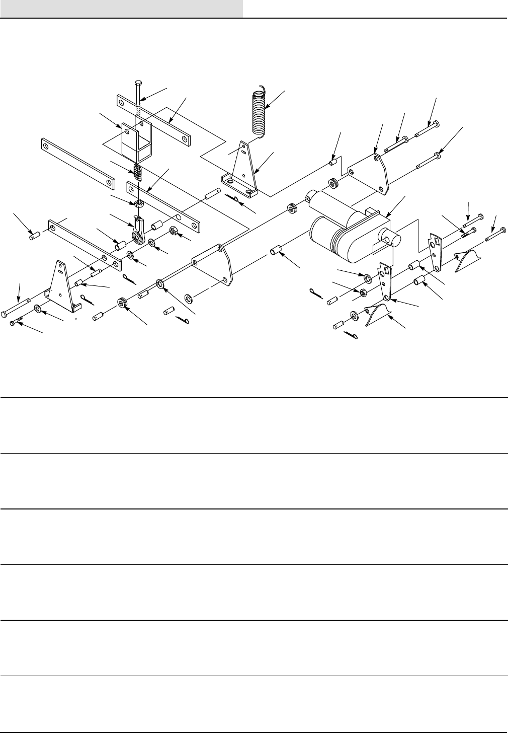
26
Scrubber Head Mounting
Machine
Frame
12
3
4
5
6
7
8
9
11
12
13
14 16
17
18
20
21
23 26
28 30
31
32
33
35
36
19
22
27
24
25
29
34
10
15
12
Ref. Part No. Description Qty.
1 611 272 000 Screw, Hex Hd., 1/2- 20 UNF x 4.5 1
2 069 760 450 Arm Head 2
3 611 271 000 Spring Holder 1
4 069 762 067 Spring, Comp., 1.00” OD, .50” ID, 2.00” LG 1
5 069 760 449 Arm Head 2
6 069 767 162 Nut, Hex Std., 1/2- 20 UNF, ZP 1
7 069 767 091 Rod End 1
8 069 760 443 Spacer, 0.50” ID, 1.50” LG, .06” Thick, Metal 2
9 069 760 417 Sleeve, Bearing, 12.7 x 8.4 x 14 6
10 069 764 083 Pin, Clevis, .50” x 5.25” LG 1
11 200 031 496 Sleeve, Hex Hd., M08 x 35 8
12 630447 Washer, Nylon, 12.7 x 25.4 x .8 18
13 069 760 416 Bearing, Journal, 12.7 x 12.7 8
14 069 767 177 Sleeve, Bearing, 12.7 x 8.4 x 20 2
15 14880.5 Washer, Flat, ANSI- A, .31” Wide, ZP, M08 8
16 200 160 017 Nut, Hex Lock, M08 10
17 578421 Pin, Cotter, .12” x 1.00” LG 6
18 626084 Scrubber Head Mounting Bracket 2
19 611 241 000 Spring, Ext., 1.00” OD, 4.50” LG, .095” Wide 2
20 579144 Washer, Plain, ANSI- A, .31” Wide, ZP, M08 3
21 611 500 000 Washer, Plain, ANSI- A, .50” Narrow, ZP 1
22 069 760 458 Bearing, Journal, 9.5 x 5.3 LG 2
23 611 064 000 Bellcrank, Head Linkage 2
24 069 764 081 Pin, Clevis, .38” x 2.25” LG 1
25 630448 Pin, Clevis, .5” x 2.25” LG 1
26 611 105 000 Pin, Clevis, .38” x 2.62” LG 1
27 069 762 436 Actuator, Linear, 36VDC, 102 mm Stroke 1
28 069 760 443 Spacer, 0.50” ID, 1.50” LG, .06” Thick, Metal 1
29 611 098 000 Pin, Clevis, .50” x 1.75” LG 1
30 611 500 000 Washer, Plain, ANSI- A, .50” Narrow, ZP 4
31 579028 Nut, Hex Lock, M08 1
32 069 764 179 Spacer, .37” ID x 1.12” Long 1
33 630432 Screw, Hex Hd., M06 x 50mm, DIN 933, ZP 1
34 611 099 000 Pin, Clevis, .38” x 2.62” LG 1
35 069 764 635 Spacer, 0.50” ID, 1.50” LG, .06” Thick, Metal 1
36 612 062 000 Switch Actuator Link 2
STANDARD PARTS
265XP (12- 02) 27
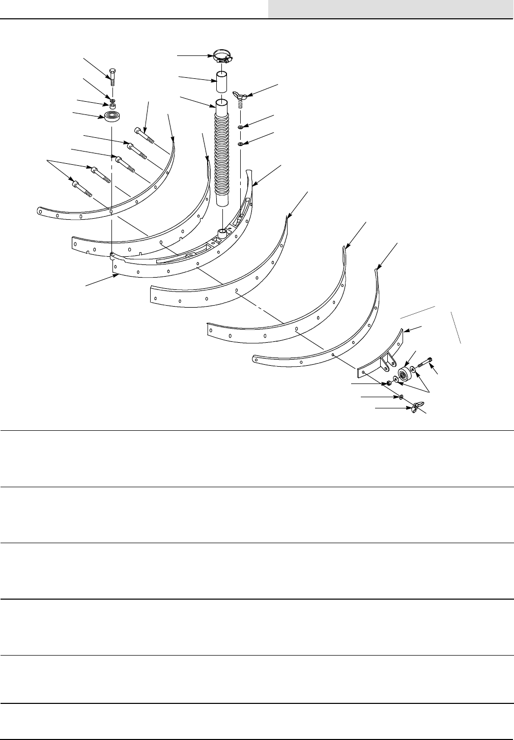
Squeegee Assembly
SQUEEGEE BLADE KIT #199 201 017
(Includes Items 10, 18, and 19)
2
3
4
8
7
6
22
20
24
23
26
27
28 25
19
18
17
16
15
14
13
11
5
12
9
10
1
21
29
Ref. Part No. Description Qty.
1 469 764 914 Asm, Squeegee 26” 1
Y2 069 760 092 Screw, Hex Hd., .31- 18 UNC x 1.75” 2
Y3 069 760 082 Washer, Plain, ANSI- A, .25” Wide, ZP 2
Y4 630450 Wheel, Rubber, 76 x 22 Wide 2
Y5 612 184 000 Screw, Carriage, 1/4- 20 UNC x 1.5 2
Y6 612 185 000 Screw, Carriage, 1/4- 20 UNC x 2.0 2
Y7 612 186 000 Screw, Carriage, 1/4- 20 UNC x 2.5 2
Y8 612 187 000 Screw, Carriage, 1/4- 20 UNC x 2.75 2
Y9 069 760 605 Strip, Retainer, Front 1
Y10 067 760 602 Blade, Squeegee, Front 1
11 140308 Clamp, Hose 1- 5/16 to 2- 1/4 1
12 160632 Sleeve, Squeegee Hose 1
13 626104 Squeegee Hose 1
Y14 069 764 149 Screw, Wing, .50- 13 x 1.00” 2
Y15 069 760 091 Washer, Plain, ANSI- A, .50” Wide, ZP 2
Y16 059 650 290 Washer, Nylon, Adjusting Knob 2
Y17 469 764 803 Squeegee, Machined, (Molded Version), 26” 1
Y18 067 760 601 Blade, Squeegee, Rear 1
Y19 067 760 603 Strip, Back Up, Squeegee 1
Y20 069 760 604 Squeegee Band, Rear, 26” Size 1
Y21 600218 Asm, Squeegee Wheel 1
Y22 600184 Bracket, Squeegee Wheel 1
Y23 630477 Wheel, 2” OD, .38” Gray 1
Y24 600187 Screw, Shoulder 3/8” x 1- 1/4” 1
Y25 140020 Washer, Flat 3/8” 2
Y26 140546 Nut, Lock Nylon Insert 5/16- 18 1
Y27 069 762 311 Washer, Flat, 7.9 ID, 19, 1.7, .25”, SS 8
Y28 140536 Nut, Wing, 1/4- 20 UNC 8
Y29 103070 Bushing, Wheel 2
= ASSEMBLY
Y= INCLUDED IN ASSEMBLY
STANDARD PARTS
265XP (03- 99)
28
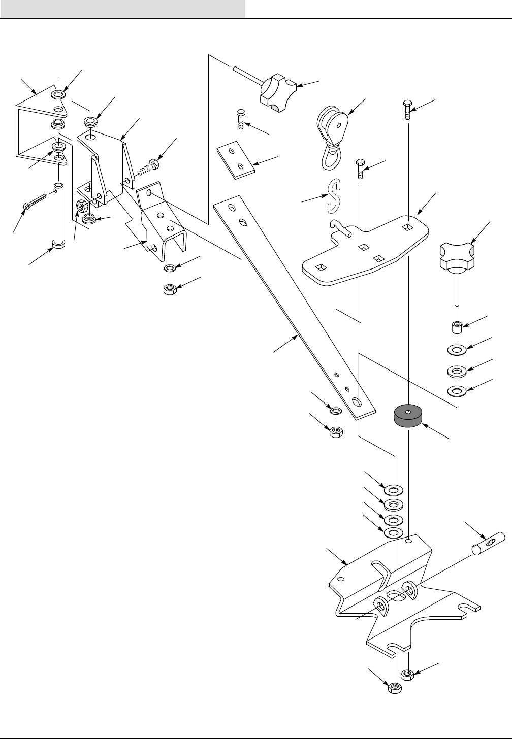
Squeegee Arm Assembly
Machine
Frame
(Ref)
8
28
7
4
17
16
15
15
14
18
19
20
19
21
26
6
5
4
3
4
9
10
22
23
2
1
13
12
11
19
20
19
24
25
27
27
29

STANDARD PARTS
265XP (03- 99) 29
Squeegee Arm Assembly
Ref. Part No. Description Qty.
601731 Kit, Squeegee Swivel Arm Replacement (Includes #1 - 29) 1
1 069 764 065 Pin, Clevis .38” Dia x 4.62” 1
2 578421 Pin, Cotter .12” x 1.00” 1
3 579144 Washer, Flat 1
4 630095 Bearing, Flange 4
5 231072 Bracket, Squeegee Swivel 1
6 200 032 503 Screw, Hex Head, M08 x 60mm 1
7 200 160 017 Nut, Hex, M08 1
8 626067 Bracket, Squeegee Spring Mounting 1
9 140016 Washer, Lock, Spring, ANSI, .25” ZP, 06 2
10 579029 Nut, Hex Std., M06 x 1.00”, DIN 943P 2
11 200 031 483 Screw, Hex Head, M06 x 20mm 2
12 069 764 155 Plate, Squeegee Spring Back- up 1
13 602509 Pulley, Swivel Eye 1
14 602828 Bracket, Squeegee Pulley Zinc 1
15 626143 Knob, Plastic, .31- 18 UNC x 2.5” 2
16 602 068 000 Screw, Carriage, .31- 18 UNC x1.25”, ZP 2
17 069 767 077 Screw, Carriage, .31- 18 UNC x.75”, ZP 2
18 069 764 154 Sleeve, 12.7 OD x 8.5 ID x 12.7mm 1
19 630447 Washer, Nylon, 123.7x25.4x0.8 4
20 626149 Washer, Rubber, .5”x1.0”x.125” 2
21 626148 Washer, Rubber, .31” x 1.5” x .53” 2
22 140015 Washer, Split Lock 2
23 140506 Nut, Hex, Standard, .31”- 18 UNC, Zinc Plated 2
24 14880.5 Washer, Flat 1
25 626087 Bracket, Squeegee Mounting 1
26 626147 Pin, Floating Thread 1
27 140546 Nut, Hex Lock, .31- 18 UNC, Nylon Ins. 4
28 626142 Spring, Flat Squeegee 1
29 611 163 000 Hook, “S”, Squeegee Lift & Swivel 1
STANDARD PARTS
265XP (03- 99)
30
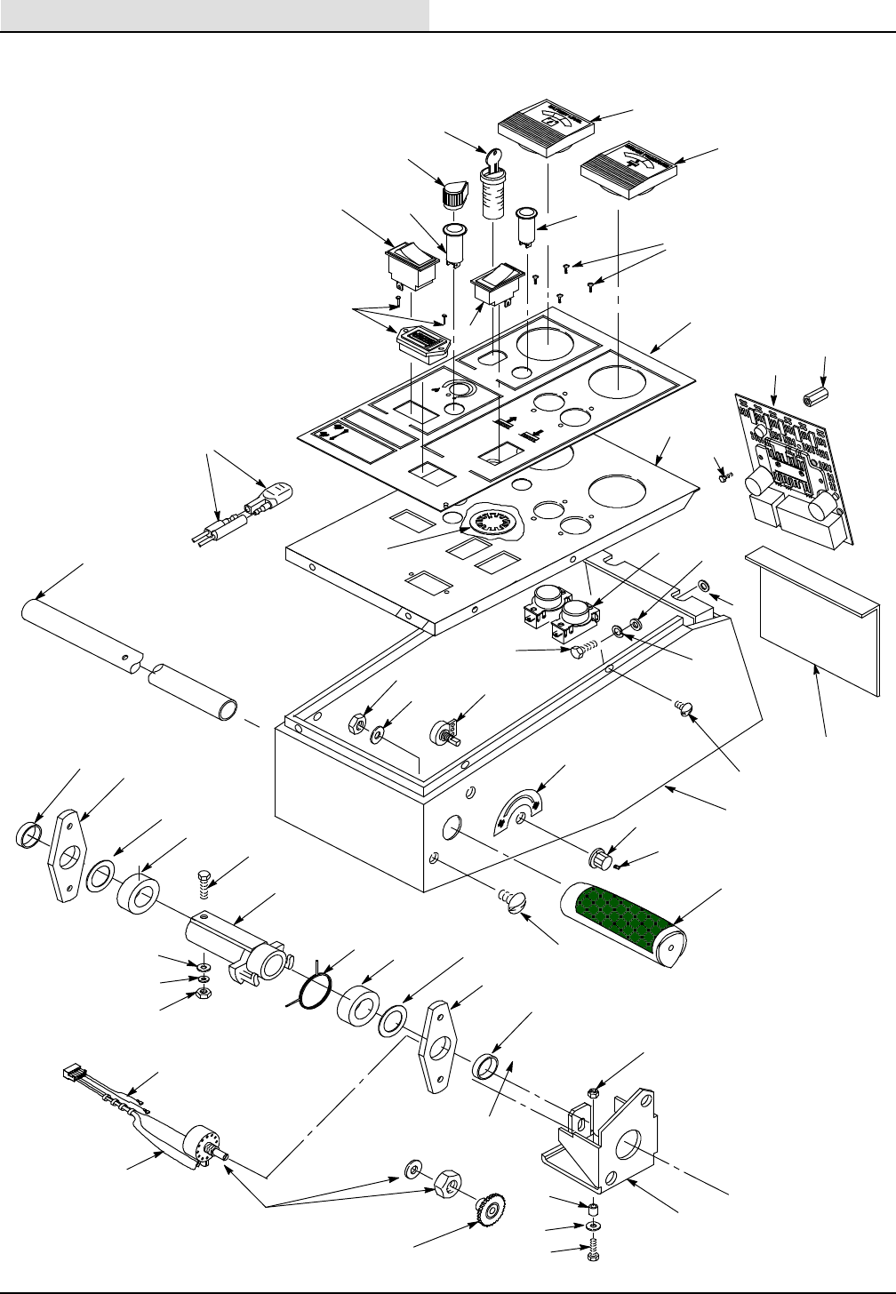
Control Console Assembly
3
5
23
24
25
28
29
26
22
31
27
32
29
28
25
24
21
20
33
34
35
17
12
11
8
1
2
10
67 4
14
13
16
41
38
39
40
30
9
18
9
7
19
36
37
15
42
44
43
43
48
49
50
46
45
47
51

STANDARD PARTS
265XP (07- 00) 31
Control Console Assembly
Ref. Part No. Description Qty.
1 610026 Meter, Battery 36VDC 1
2 611411 Meter, Pad Pressure, 19 Amp 36VDC 1
3 130785 Switch, Keylock 1
069 762 236 Key, Illinois F315 Doublesided 1
602018 Kit, Replacement For Singlesided Keys 1
4 626114 Light, Pilot, Green 36V 1
5 626121 Knob, Water Valve 1
6 626101 Light, Pilot, Blue 36V 1
7 039 705 081 Switch, Rocker 15 Amp 2
8 600561 Decal, Console 1
9 611 226 000 Screw, Truss Hd., #06- 32 x .25” 4
10 630143 Meter, Hour 18- 60VDC 1
11 069 762 306 Washer, Lock, Internal, 02.0 ID 1
12 626009 Cover, Console 1
13 626128 Switch, Push Button 2
14 579210 Washer, Flat, 6.4mm, 18.0, 1.5 6
15 140016 Washer, Lock, 1/4” 6
16 200 609438 Screw, Hex Hd., M06 x 16mm 6
17 626006 Console, 1
18 578 141 000 Screw, Pad Hd., Phil, M05 x 10, DN7985A, SS 6
19 611 081 000 Speed Control, PMC, 40 Amp 1
N/S 626157 Cover, P.C. Board 1
20 069 764 060 Screw, Truss Hd., .31- 18, 0.75” 4
21 626053 Handle Bar, Zinc Plated 1
22 200823 Grip , Handle 2
23 626151 Bracket, Potentiometer Mounting 1
24 069 760 540 Bushing, 22.2 ID x 6.4 LG 2
25 611 377 000 Bearing Block, .875” x .25 2
26 140015 Washer, Split Lock 5/16” 4
27 140506 Nut, Hex, Std., 5/16- 18 4
28 069 760 582 Washer, Nylon, 23 ID, 34 OD 2
29 630186 Collar, Shaft, 22.3 2
30 630088 Spring, Center, .072”, Zinc Plated 1
31 626131 Hub and Gear 1
32 630431 Screw, Hex Hd., M06 x 4mm, DIN 933 1
33 579210 Washer, Flat, 6.4, 18.0, 1.5, ZP 2
34 578 244 000 Washer , Lock, 1
35 579028 Nut, Hex Lock MO6 1
36 626057 Potentiometer Assembly 1
37 630099 Gear, 28 Tooth, 24 Pitch 1
38 578579 Spacer, .25 ID x .88 OD x .5Long 1
39 602 139 000 Washer, Flat 6.4mm 1
40 200 031 444 Screw, Hex MO6 x 30 1
41 140284 Nut, Hex Nylock MO6 x 1.0 1
42 630133 Resistor, 0- 20K Speed Control 1
43 630265 Knob, Speed Limit 1
44 626168 Decal, Speed Control 1
45 611 291 000 Screw, Phil Hd #08- 32x.50 2
46 611440 Decal, Fuse Specification 1
47 140958 Stand- off, 8- 32 x 3/8 x 1 2
48 600742 Shield, Speed Control 1
49 069 764 206 Diode Replacement 1
50 601 085 000 Decal, P.M.C. Connection 1
51 606374 Gasket 1
STANDARD PARTS
265XP (03- 99)
32
Tank Assembly
2
3
5
6
18
7
8
9
16
15
24
20
56
25
26
27
29
31
28
19
22
21
32
33
35
36
37
39
38
23
17
34
11 12 7
13
14
10
52
1
57
12
51
30
41
45
44
43
53 54
55
4
50 46
47
49
48
42
40
58

STANDARD PARTS
265XP (07- 00) 33
Tank Assembly
Ref. Part No. Description Qty.
1 600385 Screw, Pan Head Phil., M6 x 20 1
2 069 762 445 Label, Info, Attention: Hot Water 1
3 578729 Decal, Read Manual 1
4 630055 Cover, Tank 2
5 630367 Gasket, Recovery Tank Cover 2
6 626006 Console, 265 1
7 579210 Washer, Flat, 6.4mm x 18.0 x 1.5 9
8 140016 Washer, Lock, Spring, ANSI, .25” ZP 6
9 200 031 436 Screw, Hex Head, M06 x 16mm 6
10 630420 Decal, Flammable Material 1
11 578 187 000 Screw, Pan Head Phil, M06 x 12MM, SS 2
12 200 655 017 Washer, Lock, Spring, 6.1mm, SS 2
13 630053 Mount, Float Cage 1
14 231076 Strap, Float Cage 1
15 608364 Tank, Solution, Green 1
16 626202 Gasket, FR (.330M) 1
17 626203 Gasket, FR (.914M) 1
18 630052 Float, Cage w/ Ball, 12 x 12 Screen 1
19 575 328 000 Fitting, Plug, .5” NPT 1
20 140016 Washer, Lock, Spring, ANSI, .25” ZP 2
21 580 025 000 Washer, Lock, Int., #10, ZP 2
22 626042 Plate, Rod Support 1
23 200 058 384 Screw, Flat Head, Slot, M05 x 14mm 2
24 626043 Strap, Tank Tie 1
25 200 031 436 Screw, Hex Head, M06 x 16mm 2
26 601 104 000 Fitting, Elbow, .5” Hose x .5” NPT 1
27 626041 Spacer, 6.3 x 9.4 x 80, Steel 3
28 630024 Filter, Solution Feed, 60 Mesh 1
29 626092 Gasket, Vac Fan 1
30 140307 Clamp, Hose 3/4” x 1- 3/4” 1
31 626161 Spacer, .5” x .63” x 3.0 1
32 626200 Vac Fan, .75 HP, High Performance 1
611 340 000 Carbon Brush, Vac Fan (Order 2) 2
33 626103 Extension, Vac Fan 1
34 626033 Decal, Operation 1
35 140016 Washer, Lock, Spring, .25” ZP 3
36 626123 Screw, Hex Head, M06 x 100mm 3
37 611 205 000 Clamp, Hose, TYT SNP- 50, 2.0- 2.3’ 1
38 608366 Tank, Recovery, Green 1
39 611413 Hose, Vac Extension, 50.8 ID x 230 1
40 630147 Plug, 3/4” NPT 1
41 630139 Fitting, Plug Hex 3/8” 1
42 630134 O- Ring, 16mm OD x 3.5mm 1
43 140308 Clamp, Hose 1- 5/16” to 2- 1/4” 1
44 160632 Sleeve, Squeegee Hose 1
45 626104 Hose, Recovery Tank 38.1 Dia. 1
46 626015 Bracket, Tank Support 2
47 200 351 020 Washer, Lock 10.2mm 8
48 140013 Washer, Flat 3/8” 8
49 200 031 538 Screw, Hex Head, M10 x 20 8
50 626077 Spacer, Tank 1
51 602739 Gasket, FR (.152M) 1
52 626036 Decal, Maintenance 1
53 140872 Screw, #6 x 3/8” PNPHL 8
54 630390 Washer, Flat .15, .56, .04 8
55 630056 Hinge, Recovery Tank 2
56 626162 Cap, Tapered 3.125” 1
57 059 650 283 Washer, Flat 6.4mm, 18.0, 1.6 1
58 608369 Decal, 265XP 2
STANDARD PARTS
265XP (03- 99)
34
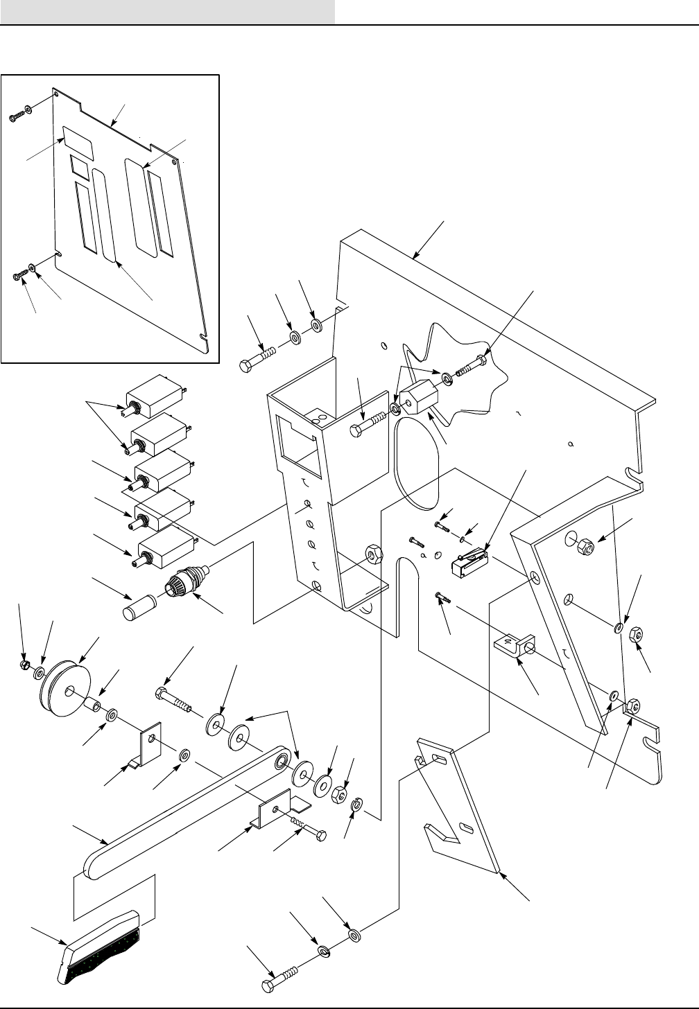
Electrical Panel
1
2
3
4
5
6
7
10
12
8
11 12
13
14
15 16
17
18
19
20
21
22
23
12
24
25
26
27
25
28 25
29
32
30 31
33
34
35
38
12
39
37
34
9
36
41
10
40
42
44
43

STANDARD PARTS
265XP (03- 99) 35
Electrical Panel
Ref. Part No. Description Qty.
1 20796 Circuit Breaker, 17 AMP 2
2 611 110 000 Circuit Breaker, 10 AMP 1
3 069 764 092 Circuit Breaker, 15 AMP 1
4 572 011 000 Circuit Breaker, 19 AMP 1
5 601091 Fuse, 2 AMP, 3AG, Fast Blow 1
6 578418 Fuseholder, Bayonette 1
7 626007 Panel, Electrical 1
8 200 031 436 Screw, Hex Head, M06 x 16mm 4
9 140285 Nut, Hex M10 x 1.5 1
10 579210 Washer, Flat, 6.4 x 18.0 x 1.5, ZP 8
11 578 189 000 Screw, Hex Head, 1/4- 20 UNC x .75” 1
12 140016 Washer, Lock 1/4” 9
13 578427 Standoff, Terminal 1
14 069 762 115 Screw, Hex Head, 1/4- 20 x .5” 1
15 200 051 274 Screw, Fill. Head, Slot, M03 x 30mm 2
16 140026 Washer, Flat #6 2
17 069 764 008 Switch, Snap, 25 Amp, Roller, SPNO & C 1
18 200 160 018 Nut, Lock M10 1
19 200 031 436 Screw, Hex Head, M06 x 16mm 1
20 069 760 792 Bracket, Lift Cable 1
21 069 764 054 Washer, Lock, Spring, ANSI, #06, ZP 2
22 200 102 012 Nut, Hex, M03- .5 2
23 200 634 016 Nut, Hex, M06 1
24 579028 Nut, Hex Lock, M06 2
25 579210 Washer, Flat, 6.4 x 18.0 x 1.5 mm, ZP 2
26 630426 Pulley, Cable, «2” x 3/16” 1
27 626047 Spacer, 6.2 x 9.3 x 12 mm, ZP 1
28 626045 Bracket, Cable Retaining 1
29 231071 Arm, Squeegee Lift 1
30 626146 Bracket, Switch Engagement 1
31 630432 Screw, Hex Head, M06 x 50mm 1
32 630209 Grip, Squeegee Lift 1
33 601 094 000 Screw, Hex Head, M10 x 45 1
34 611 375 000 Washer, Flat 2
35 059 650 290 Washer, Nylon 2
36 140333 Washer, Lock 1
37 626145 Bracket, Squeegee Catch 1
38 140012 Washer, Plain, ANSI- A, #12, ZP 2
39 200 031 436 Screw, Hex Head, M06 x 16mm 2
40 626011 Cover, Rear Panel 1
41 578 141 000 Screw, Pan Phil M5 x 10 4
42 069 780 017 Decal, Warning 1
43 600817 Decal, Circuit Breaker 1
44 600818 Decal, Squeegee Lift 1
STANDARD PARTS
265XP (03- 99)
36
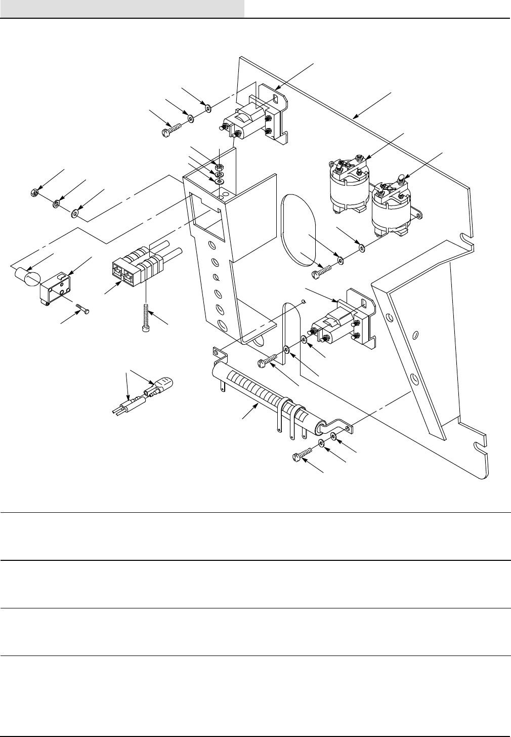
Electrical Panel (cont’d.)
2
3
4
7
8
9
2
3
4
16
14
13
10
8
9
11 12
1
5
6
6
2
3
4
17
3
1
4
15
19
Ref. Part No. Description Qty.
1 611 157 000 Contactor, 36VDC, 100A, SPNO, #120 2
2 140012 Washer, Plain, ANSI- A, #12 Wide, ZP 9
3 069 762 005 Washer, Lock, Spg., ANSI, #10, ZP 9
4 578 141 000 Screw, Pan Head, Phil, M05 x 10, DIN7985, SS 9
5 626007 Electrical Panel (Ref) 1
6 069 760 440 Contactor, SPDT, 100A 2
7 069 762 159 Nut, Hex, Std., #6- 32, UNC, ZP 2
8 069 764 054 Washer, Lock, Spg., ANSI, #06, ZP 4
9 140026 Washer, Plain, ANSI- A, #06, ZP 4
10 200 102 012 Nut, Hex, Std., M03 x .5, DIN 934 ZP 2
11 626050 Spacer, 3.6mm x 7.9 x 9.5, Nylon 2
12 611 266 000 Switch, Mini, Snap, SPDT 1
13 200 051 274 Screw, Fill. Hd., Slot, M03 x 30mm 2
14 626130 Plug, Charger w/Cable Assembly 1
15 601 079 000 Screw, Socket Head, #6- 32 UNC x 1.0” 2
16 612453 Resistor, .10 OHM, 100 Watt Adj. 1
17 140012 Washer, Flat, 6.4 x 18 x 1.5, ZP 2
18 626016 Wire Harness, Main Asm (Not Shown) 1
19 069 764 206 Diode Replacement 2
STANDARD PARTS
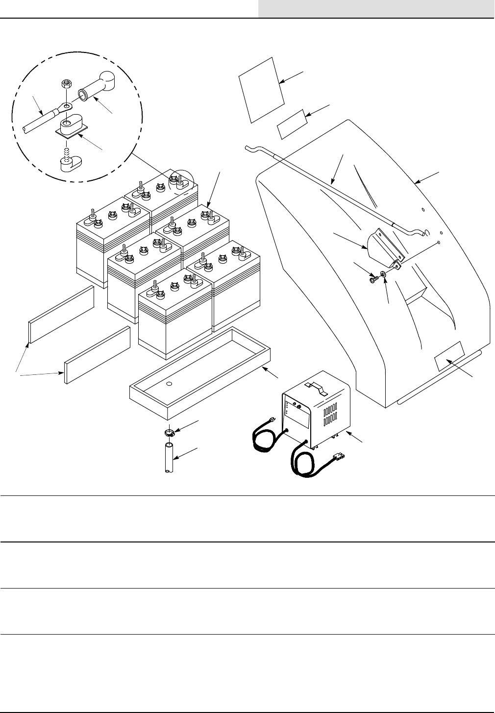
265XP (12- 02) 37
Battery Group
11
6
8
9
7
13
12
14
10
2
3
5
4
1
15
16
17
Ref. Part No. Description Qty.
1 608368 Shroud, Front Green 1
2 626 108 Rod, Hood Support 1
3 626 109 Bracket, Rod Retaining 1
4 578 141 000 Screw, Pan Phl M5x10 3
5 069 762 005 Washer, Lock 3
6 608189 Decal, Nobles Logo 1
7 626 019 Battery Tray 1
8 069 764 220 Clamp, Hose 1
9 612 235 000 Hose, 11/16 x 460MM 1
10 626 076 Spacer, Battery Foam 2
11 222280 Battery, 6 Volt 240 AMP 6
12 611 221 Battery Cable Terminal Boot Black 5
611 222 Battery Cable Terminal Boot Red 5
13 611 223 Cover, Terminal 12
14 611 116 000 Battery Cable, #04GA 5
15 626 096 Decal, Wiring Diagram 1
16 601 095 000 Decal, Caution Battery Connect 1
17 469 760 868 Charger, Battery 36VDC 25A 120 VAC 1
BREAKDOWNS
265XP (03- 99)
38
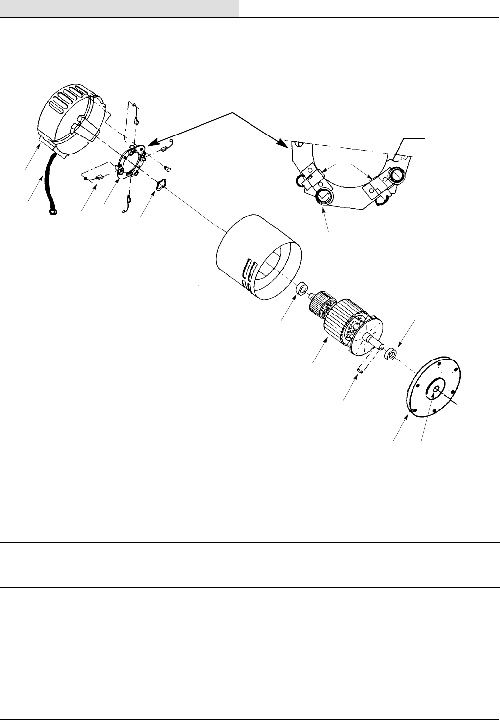
Pad Motor & Drive Motor
1
2
34
5
6
7
8
9
4
10
3
11 12
Ref. Part No. Description Qty.
069 762 427 Motor, 36V, .5hp, 320rpm (Complete) 1
1 611 284 000 Asm., Lead 1
2 611 288 000 Bracket, Commutator 1
3 611 287 000 Asm., Brush (Must order 4) SetOf4
4 611 283 000 Asm., Brush Board (Includes 3 & 10) 1
5 602 087 000 Washer, Helical 1
6 602 088 000 Bearing 1
7 611 282 000 Asm., Armature (Includes 6 & 9) 1
8 069 764 080 Key, Shaft 1
9 140124 Bearing 1
10 602 131 000 Spring, Brush (Must order 4) SetOf4
11 611 286 000 Endbell, Motor 1
12 601 077 000 Seal, Oil 1
OPTIONS
39
265XP (03- 99)
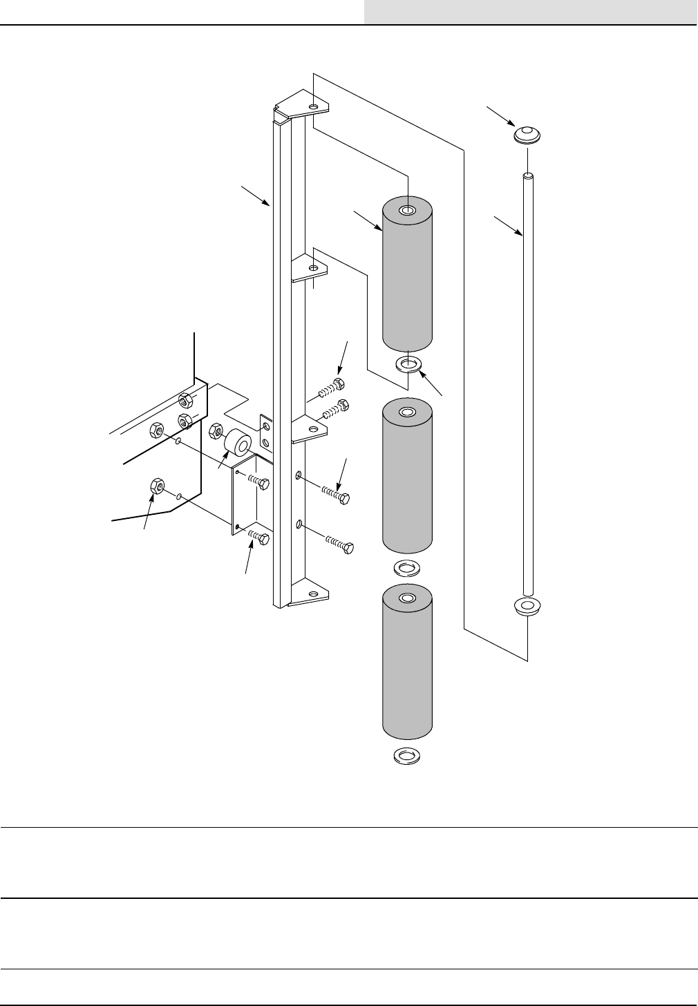
Wall Roller Kit
1
2
3
6
7
5
49
8
7
Front Right
Corner of
Machine
Ref. Part No. Description Qty.
626708 Kit, Wall Roller 1
1 626020 Bracket, Wall Roller, LH 1
1 626091 Bracket, Wall Roller, RH 1
2 200 160 017 Nut, Hex, Standard, M08- 1.00 12
3 626140 Spanner, 9.53x25.4,x30.0 4
4 626021 Roller, Upper 6
5 612 161 000 Washer, Flat, 13.4 x 21.8 6
6 200 031 501 Screw, Hex Head, M08 x 50 4
7 200 031 486 Screw, Hex Head, M08 x 16 8
8 069 764 114 Cap, Push- On 4
9 626156 Shaft, High Roller 2
OPTIONS
265XP (03- 99)
40
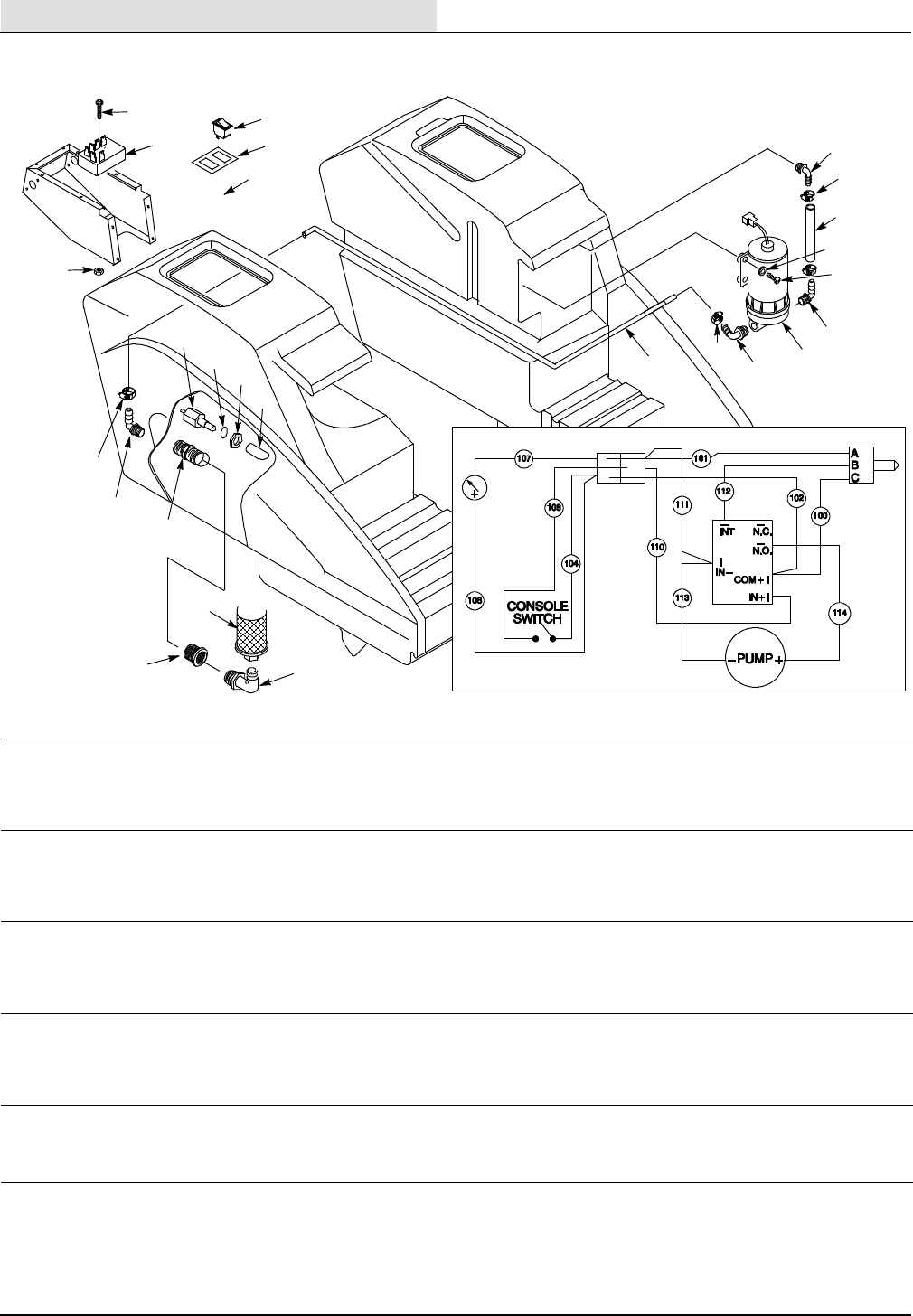
EStOption Components
1
12
15
13 14
16
7
2
3
4
5
89
10
11
21
17
20
19
18
22
21
21
23
6
Harness
BATTERY
LEVEL
METER
CONNECTOR SENSOR
TIMER
20
Ref. Part No. Description Qty.
626700 Kit, Extended Scub 1
1 626102 Timer, 36VDC, Range - 30 Sec. 1
2 578 008 000 Screw, M05 x 31.3 1
3 140283 Nut, Lock M05 1
4 039 705 081 Switch, Rocker 15A 1
5 120068 Decal, Switch 1
6 626018 Wire Harness 1
7 630137 Sensor, Liquid Level, 10- 40 VAC 1
8 630134 O- Ring, Sensor 1
9 140607 Nut, Sensor 1
10 626169 Deflector, Water 1
11 578 037 000 Fitting, Elbow, .5” Hose x .75” 1
12 630385 Fitting, Nipple, 3/4”NPT, Nylon 1
13 578 036 000 Fitting, Bush, 1.0” MPT x 3/4” FPT 1
14 578 034 000 Fitting, Elbow, 1” NPT, Street 1
15 578 014 000 Filter, SRS, 100 Mesh 1
16 612 104 000 Tubing, Clear, Bulk .64m
17 626106 Pump, 36 VDC, SRS 1
18 140012 Washer, Flat 3/16” 4
19 602 168 000 Screw, #10- 32 x 1” 4
20 578 039 000 Fitting, Elbow, .5” Hose x .38” NPT 2
21 140310 Clamp, Hose 5/16”- 7/8” 4
22 612 104 000 Tubing, Clear, Bulk .16m
23 601 104 000 Fitting, Elbow .5 Hose x .5 NPT 1
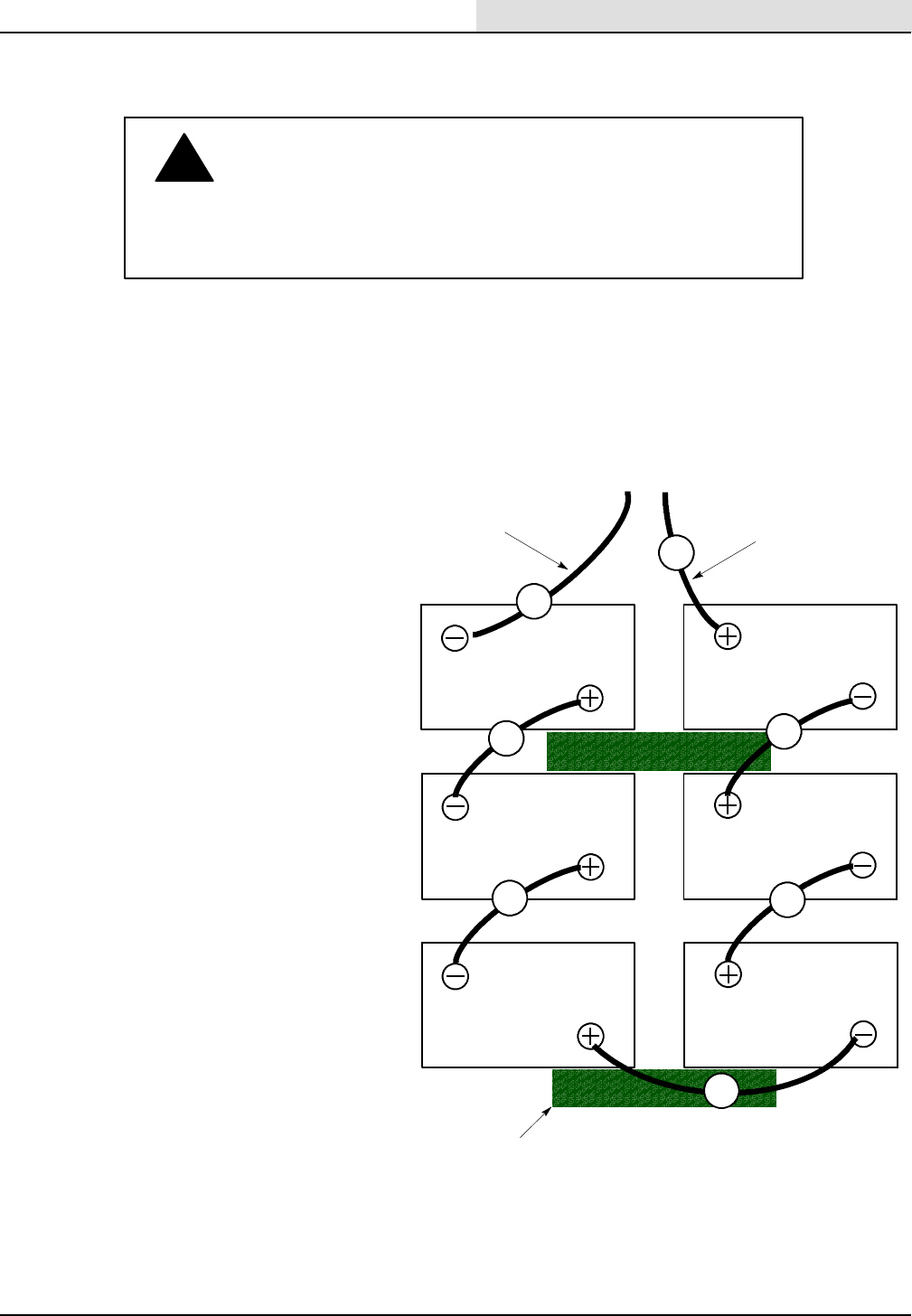
BATTERY INSTALLATION
265XP (03- 99) 41
CABLE #1 CABLE #2
FRONT
FROM
ELECTRICAL
PANEL
Step 1:
Turn Key to OFF. This prevents any
motors from accidentally starting
when battery connections are made.
Step 2:
Carefully set batteries in
compartment and arrange battery
posts as shown.
Step 3:
Insert foam spacers between
batteries as shown and place a
translucent terminal cover over each
post.
Step 4:
Connect cables to battery posts in
order as labeled (RED to POSITIVE
& BLACK to NEGATIVE). Cover post
with rubber boot.
NOTE: Once final battery cable
connection is made the scrubber
head will automatically raise to
transport position. This is normal.
CAUTION: Be careful not to bridge
wrench from post to post when
connecting cables. This could cause
sparking and create an explosive
hazard.
A
B
C
D
E
F
G
INSTRUCTIONS
BATTERY SPECIFICATIONS:
6 - 6 VOLT 235AMP @ 20 hr rate
FOAM SPACERS
WARNING: Batteries emit hydrogen gas. Explosion
!
FOR SAFETY: When servicing machine, wear protective gloves
when handling batteries or battery cables. Avoid contact with
battery acid.
or fire can result. Keep sparks and open flame away.
Keep battery compartment open when charging.
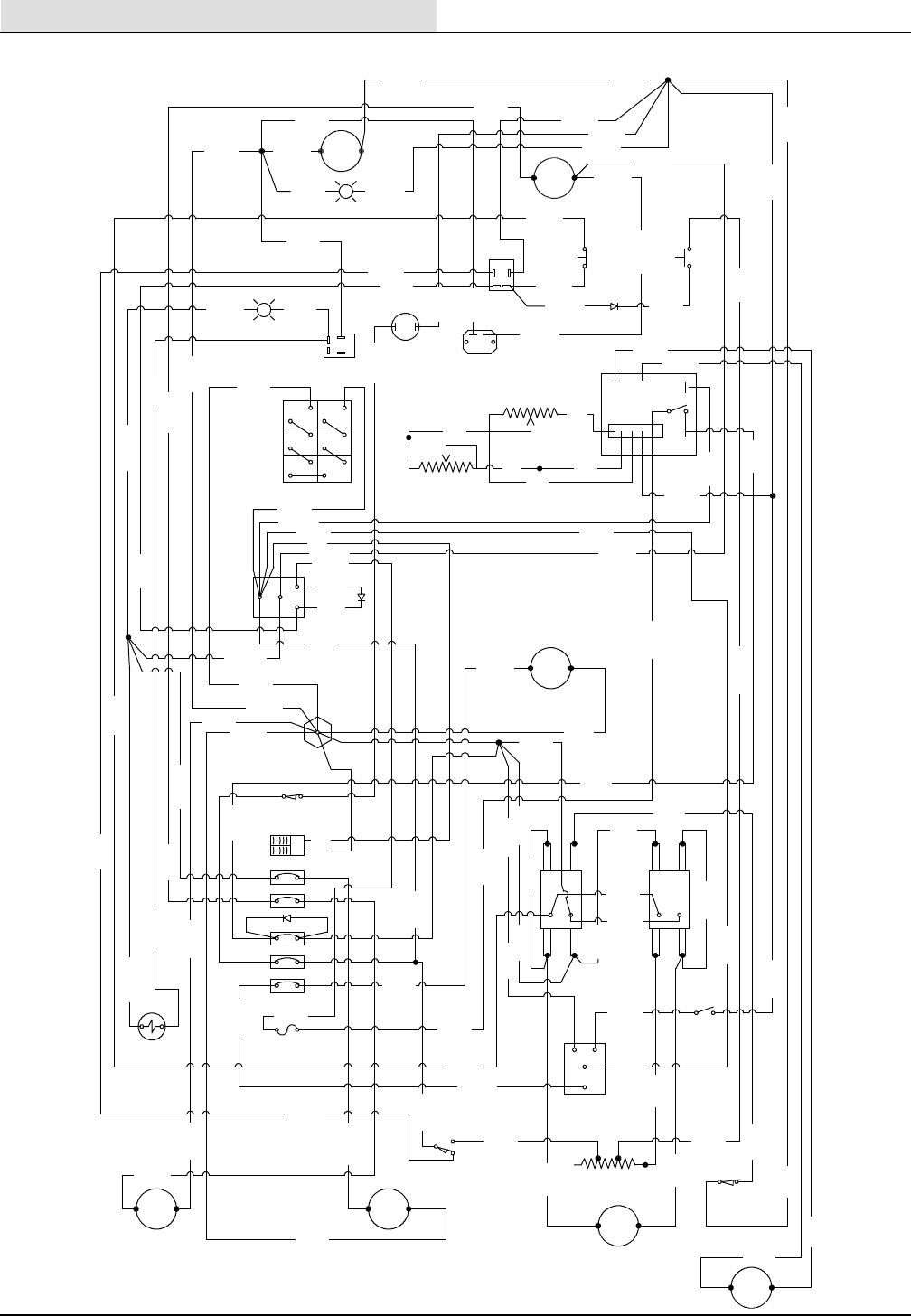
ELECTRICAL DIAGRAMS
Tennant 26- inch Automatic Scrubber265XP (03- 99)
42
Wiring Diagram
VACUUM
CONTACTOR
ACTUATOR
CONTACTORS
LEFT
BRUSH
RIGHT
BRUSH
DOWN
LIMIT
19
R. BRUSH
L. BRUSH
DRIVE
MAIN
VAC
DRIVE
MOTOR
ACTUATOR
MOTOR
DOWN
PRESS.
RES.
VACUUM
MICRO-
SWITCH
+-
HEAD
UP
LIMIT
++- -
HOUR
METER
TWIST GRIP
SPEED CONTROL
SPEED CONTROL
(CONSOLE)
CHG. PLUG
SWITCH
NEGATIVE
STANDOFF
2AMP
DRIVE BOARD
SOLUTION
VALVE
BRUSH
CONTACTOR
17
17
10
15
CHG. PLUG
+
-
RED
BLK
BATTERY
36 V
RED
+
-
+
+
+
-
-
-+
+
+-
-
-
DRIVE
BOARD
VAC
MOTOR
SOLUTION
SWITCH
BAT.
METER
MAIN
POWER
KEY
SWITCH
”SOLUTION”
B
SCRUB
12
-+
”POWER”
G
TRANS
PRES. DEC.
SWITCH
PRES. INC.
SWITCH
BRUSH
METER
M2 M1
- 19-
B+
B-
+-
- 21-
- 20--5-
- 75-
- 20-
- 54-
P
R
U
- 89- BLK
B
L
U
E
- 88-
- 46- GRN
B
L
K
- 85-
- 84- RED - 60-
B
R
N
- 50- YEL
- 61-
B
L
K
- 54- PUR
- 62-
w
H
T
- 44-
G
R
N
- 17-
B
L
K
- 18- PNK
- 52-
P
N
K
-6- RED
- 36- YEL
-30 TAN
R
E
D
- 42-
- 74- ORG
- 81- BLK
T
A
N
- 30-
- 83- BLK
- 32- TAN
- 42A-
BLK
-7-
BLK
- 47-
BLK
- 25-
BLK
-4-
RED
B
L
K
- 97-
B
L
K
- 85-
B
L
U
E
- 96-
- 84-
RED
- 88-
BLUE
R
E
D
B
L
K
- 67-
B
L
K
- 39-
- 71A- BLK
- 72- ORG
- 65-
B
L
K
- 91-
B
L
K
-6-
R
E
D- 34-
G
R
N
- 91-
B
L
K
B
L
K
- 81-
- 28-
- 62- WHT
- 65- BLK
- 67-
B
L
K
- 39-
B
L
K
-5- BLK
- 71- BLK
- 33- BLK
- 32- TAN
- 81-
B
L
K
- 80- BLUE
-6- RED
- 22- GRN
-7-
BLK
-8-
RED
- 46-
G
R
NR
E
D
- 82-
O
R
G
- 74-
- 86-
B
L
U
E
B
L
K
-5-
-4-
RED
- 85- BLK
- 89- BLK
- 37- BLK
-1- BLK
- 86A- BLUE
- 28- RED
- 26- YEL
- 13- BLK
- 83- BLK
- 80- BLUE
-6- RED
- 12- RED
-2- RED
Y
E
L
- 14-
- 98-
B
L
U
E
B
L
K
- 97-
- 82-
R
E
D
B
L
K
- 37-
-1- BLK
- 95- BLK- 98- BLUE
-8-
R
E
D
- 24-
G
R
N
B
L
K
- 15-
- 12-
R
E
D
-5-
B
L
K
- 18- PNK
- 17- BLK
- 16- BLUE
- 58- WHT
- 76- WHT
- 56- WHT
P
U
R
- 54-
- 16-
B
L
U
E
- 74- ORG
- 46- GRN
- 14- YEL
- 93- BLK
- 10- GRN
- 16- BLUE
- 80- BLUE - 34-
G
R
N
- 44-
G
R
N
- 40- GRN
- 24- GRN
- 10- GRN
- 44A- GRN
- 82- RED
- 44A- GRN
- 15- BLK
- 37A- BLK
-11- BLK
- 37- BLK
DN
UP
- 63-
BLK
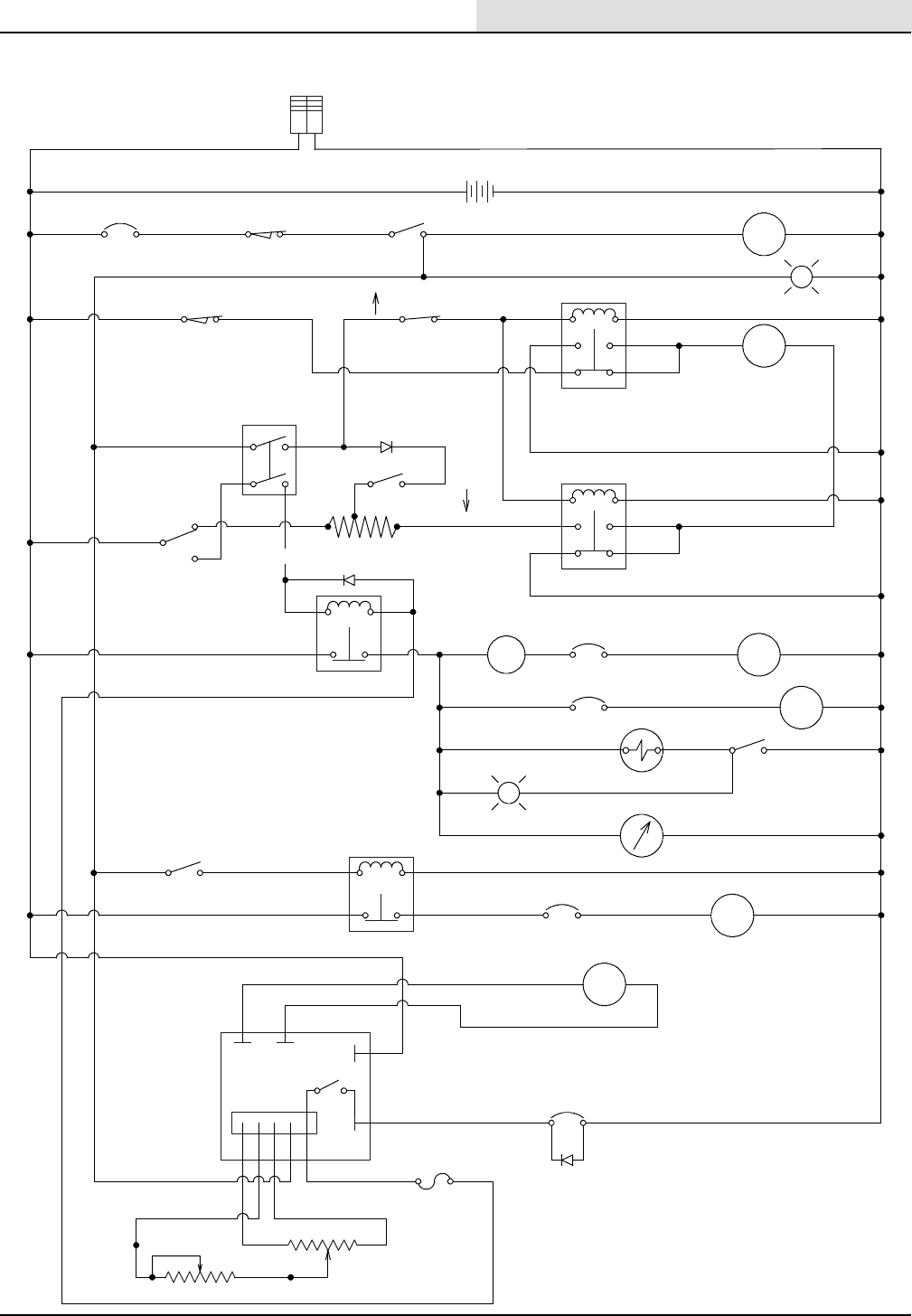
ELECTRICAL DIAGRAMS
43
265XP (03- 99)
Ladder Diagram
BATT.
METER
G
SCRUB
HEAD
ACT.
MOTOR
LEFT
BRUSH
MOTOR
RIGHT
BRUSH
MOTOR
B
VAC .
MOTOR
DOWN
PRESS.
METER
DRIVE
MOTOR
36 VDC
+-
MAIN
BREAKER CHARGER PLUG
MICROSWITCH
MASTER
KEY SW.
”POWER”
SCRUB HEAD
UPPER LIMIT
17 AMP
17 AMP SOLUTION
VALVE
SOLUTION
SWITCH
”SOLUTION”
VACUUM
MICROSWITCH
VAC .
15 AMP
-28-
-RED-
-4-
-RED-
-8--RED- -24--GRN-
-10--GRN-
-60--BRN-
-84--RED-
-88--BLU-
-97--BLK-
-95--BLK-
-82-
-RED-
-86--BLU-
-96--BLU-
-98-
-BLU-
-80--BLU-
-11--BLK-
-85--BLK-
-89--BLK-
-93--BLK-
-39--BLK-
-33--BLK-
-62--WHT-
-44--GRN-
-34-
-GRN-
-36--YEL-
-30--TAN--6--RED-
-17--BLK-
-18--PNK-
-32--TAN-
-37--BLK-
CHARGER
PLUG
-2- -RED- -1--BLK-
-BLK-
-RED-
N.C.
-74-
-ORG-
-61--BLK-
-72--ORG-
-67--BLK-
-90-
-BRN-
-65--BLK-
-91-
-BLK-
-61--BLK-
-63--BLK-
-52--PNK-
-71--BLK-
INC. PRESS.
SWITCH
N.C.
BRUSH
-13-
-BLK-
-26-
- YEL-
HOUR
METER
-16--BLU- -15--BLK-
17 AMP
M2 M1 B+
B+ 10 A
-47-
-BLK-
-25-
-BLK-
-7--BLK-
-12--RED-
-22--BLK-
-20--BLK-
-20-
-BLK- -83--BLK-
-81--BLK-
-21--BLK-
-19-
-BLK
DECREASE
PRESS. SW.
N.C.
-56-
-WHT-
-54--PUR-
-50-
- YEL-
-42-
-RED-
-46-
-BRN-
-40--GRN- -76-
-WHT-
-58-
-WHT-
UP
DN
SCRUB HEAD
LOWER LIMIT
MODE
SWITCH
-14--YEL-
RIGHT BRKR
LEFT BRKR
VAC . MOT OR
DRIVE
-5--BLK-
2A
-WHT-
DASH POTENTIOMETER 20K
5K THROTTLE
POTENTIOMETER
-2--RED-
