987597 SCV 2426 REV F 0207 .pmd Minuteman 24 26 Rider Floor Scrubber Parts And Operator Manual
2018-04-27
: Sweepscrub Minuteman-Scv-24-26-Rider-Floor-Scrubber-Parts-And-Operator-Manual minuteman-scv-24-26-rider-floor-scrubber-parts-and-operator-manual 2722 file product_file
Open the PDF directly: View PDF ![]() .
.
Page Count: 83

Parts and Instructions Manual
SCV 24/26 Rider Scrubber
Parts
and Instruction Manual
This manual is furnished with each new MINUTEMAN SCVTM 24/26. This provides the necessary operating
and preventive maintenance instructions. Operators must read and understand this manual before
operating or servicing this machine.
This machine was designed to give you excellent performance and efficiency. For best results and
minimal cost, please follow the general guidelines below:
• Operate the machine with reasonable care.
• Follow the manufacturers suggested maintenance instructions as provided in this booklet.
• Use original Minuteman supplied parts.
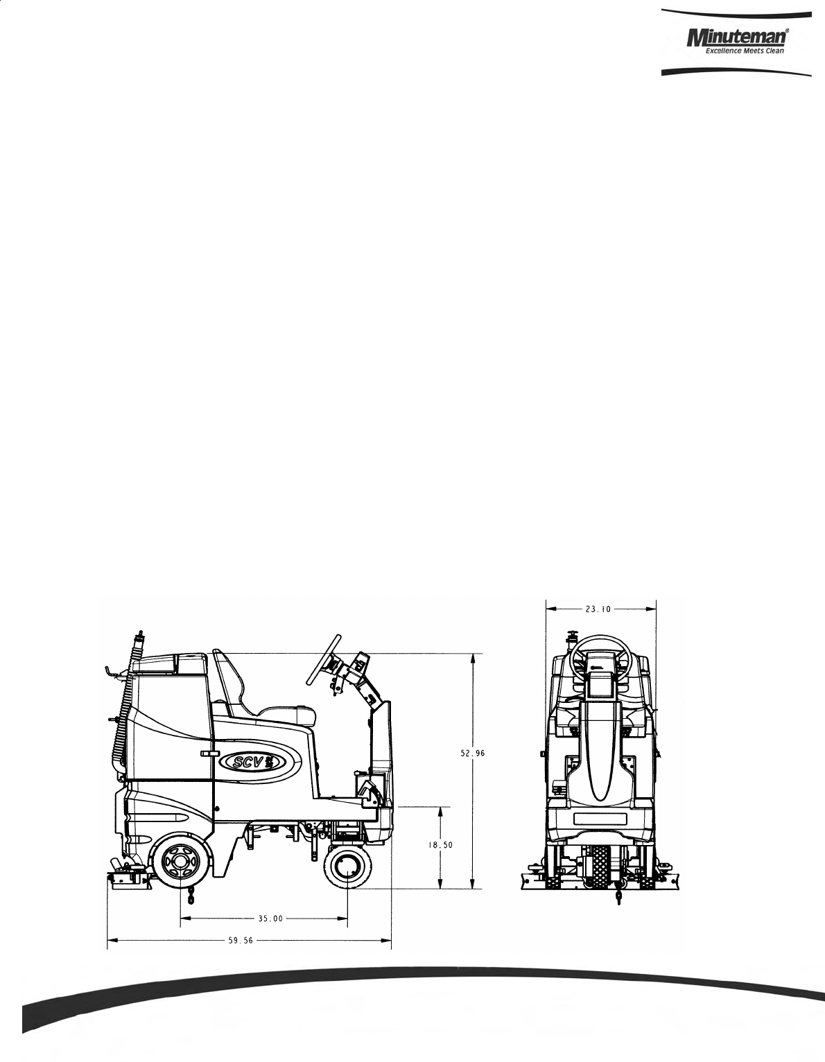
TECHNICAL SPECIFICATIONS
Model SCVTM 24/26
Model # SC240000QP \ SC240001QP
SC260000QP \ SC260001QP
Current 52 Amps
Voltage, Batteries 36 volts, 3-12volt
Battery Capacity 210 AH
Sound Level 71dB
Dimensions (LxWxH) 60" x 23" x 53" (152.4cm x 58.42cm x 134.62cm)
Gross Weight 1,027 lbs (466 kg) with batteries
637 lbs (289 kg) without batteries
Working Grade Transport 10% (7°)
Wheel to Floor Pressure 61 PSI Front, 67 PSI Rear
Parts
and Instruction
M
anual

Parts
and Instruction Manual
Table Of Contents
Important Safety Instructions ............................................................................................................ 1
For Safety During Operation ........................................................................................................... 1
For Safety When Servicing or Maintaining the Machine.................................................................. 1
Inspection............................................................................................................................................ 2
Electrical.............................................................................................................................................. 2
Batteries .............................................................................................................................................. 2
Operator Responsibility ..................................................................................................................... 2
Machine Overview .............................................................................................................................. 3
Front ................................................................................................................................................ 3
Rear ................................................................................................................................................ 4
Lower Control Console ...................................................................................................................... 5
Regular Scrub Mode ....................................................................................................................... 5
Heavy Scrub Mode.......................................................................................................................... 5
Vacuum Only Mode ......................................................................................................................... 6
Solution Control............................................................................................................................... 6
Double Scrub Mode ........................................................................................................................ 6
Transport Mode ............................................................................................................................... 6
Upper Control Console ...................................................................................................................... 7
Empty Solution Tank Indicator ......................................................................................................... 7
Low Battery Indicator ...................................................................................................................... 7
Steering Wheel ................................................................................................................................ 7
Operation of Controls ........................................................................................................................ 8
Power Save Mode ........................................................................................................................... 8
Directional Switch............................................................................................................................ 8
Accelerator Pedal ............................................................................................................................ 8
Seat................................................................................................................................................. 8
Parking Break.................................................................................................................................. 8
Battery Compartment ...................................................................................................................... 9
Emergency Disconnect Button ........................................................................................................ 9
Circuit Breakers............................................................................................................................... 9
Scrub Deck........................................................................................................................................ 10
Cylindrical Scrub Deck .................................................................................................................. 10
Disc Scrub Deck............................................................................................................................ 10
Scrub Deck Shift ........................................................................................................................... 11
Scrub Deck Installation.................................................................................................................. 12
Installation Instructions .................................................................................................................. 12
Important Note When Interchanging Scrub Decks ........................................................................ 13
Side Squeegee .................................................................................................................................. 14
Brush Changes on the Cylindrical Deck......................................................................................... 15
Rear Squeegee.................................................................................................................................. 16
Rear Squeegee Adjustment .......................................................................................................... 17
Off Aisle Wand (Optional) ................................................................................................................ 18

Parts
and Instruction Manual
The SCV Rider................................................................................................................................... 19
Machine Operation ........................................................................................................................ 19
After Use ....................................................................................................................................... 21
Maintenance Schedule .................................................................................................................. 22
Lubricating the Machine ................................................................................................................ 22
General Machine Troubleshooting .................................................................................................. 23
SCV 24/26 Fault / Diagnostic Codes ............................................................................................... 25
Exploded Views ................................................................................................................................ 26
Main Assembly I ............................................................................................................................ 26
Main Assembly II ........................................................................................................................... 27
Main Assembly BOM ..................................................................................................................... 28
Mainframe Assembly ..................................................................................................................... 29
Linkage Assembly ......................................................................................................................... 30
Linkage Assembly BOM ................................................................................................................ 31
Front Drive Assembly .................................................................................................................... 32
Drive Cable Guide Assembly......................................................................................................... 33
Steering Assembly I....................................................................................................................... 34
Steering Assembly II...................................................................................................................... 35
Steering Assembly BOM ............................................................................................................... 36
Solution Tank Assembly I .............................................................................................................. 37
Solution Tank Assembly II ............................................................................................................. 38
Solution Tank Assembly BOM ....................................................................................................... 39
Seat Assembly .............................................................................................................................. 40
Electrical Panel Assembly ............................................................................................................. 41
Recovery Tank Assembly I ............................................................................................................ 42
Recovery Tank Assembly II ........................................................................................................... 43
Recovery Tank BOM ..................................................................................................................... 44
Pump Assembly ............................................................................................................................ 45
Pump Assembly BOM ................................................................................................................... 46
Rear Axle Assembly ...................................................................................................................... 47
Squeegee Mechanism Assembly .................................................................................................. 48
Rear Squeegee Assembly ............................................................................................................. 49
Battery Panel Assembly (Left Hand Side) ..................................................................................... 50
Battery Panel Assembly (Right Hand Side) ................................................................................... 51
24” Cylindrical Scrub Deck Assembly I (Items 1-31) ..................................................................... 52
24” Cylindrical Scrub Deck (Items 32-62)...................................................................................... 53
24”Cylindrical Scrub Deck BOM .................................................................................................... 54
26” Scrub Deck Assembly I (Items 1-31) ....................................................................................... 55
26” Cylindrical Scrub Deck Assembly II (Items 32-62) .................................................................. 56
26” Cylindrical Scrub Deck BOM ................................................................................................... 57

Parts
and Instruction Manual
24” Disc Scrub Deck Assembly I ................................................................................................... 58
24” Disc Scrub Deck Assembly II .................................................................................................. 59
24” Disc Scrub Deck BOM ............................................................................................................ 60
26” Disc Scrub Deck Assembly I ................................................................................................... 61
26” Disc Scrub Deck Assembly II .................................................................................................. 62
26” Disc Scrub Deck BOM ............................................................................................................ 63
Cylindrical Side Squeegee (Left Hand Side) ................................................................................. 64
Cylindrical Side Squeegee (Right Hand Side)............................................................................... 65
Disc Side Squeegee (Left Hand Side)........................................................................................... 66
Disc Side Squeegee (Right Hand Side) ........................................................................................ 67
24” Cylindrical Brush Assembly ..................................................................................................... 68
24” Disc Brush Assembly .............................................................................................................. 69
26” Cylindrical Brush Assembly ..................................................................................................... 70
26” Disc Brush Assembly .............................................................................................................. 71
Plumbing Diagram ............................................................................................................................ 72
Wiring Diagrams ............................................................................................................................... 73
Minuteman International Made Simple Commercial Limited Warranty........................................ 77

Parts and Instruction Manual
Page 1
Operators must read and understand this manual before operating or maintaining this machine.
Do not operate this machine in flammable or explosive areas.
This machine is designed solely for scrubbing dirt and dust in an indoor environment. Minuteman does not recommend
using this machine in any other capacity.
The following information below may cause a potential hazard to the operator and equipment. Read this manual carefully
and be aware when these conditions can exist. Take necessary steps to locate all safety devices on the machine and
train the personnel operating the machine. Report any machine damage or faulty operation immediately. Do not use
machine if it is not in proper operating condition.
Keep hands and feet clear of moving parts while machine is in operation.
Make sure all safety devices are in place and operate properly. All covers, doors and latches must be closed and fastened
before use.
During operation, attention should be paid to other persons in the work area and especially if small children are present.
Electric motors and components can cause an explosion when operated near explosive materials or vapor. Do not
operate this machine near flammable materials such as solvents, thinners, fuels, grain dust, etc.
Store or park this machine on a level surface only, with the key switch in the off position. To prevent unauthorized use,
machine should be stored or parked with the key removed.
This machine is designed for level operation only. Do not operate on ramps or inclines.
This machine is not suitable for picking up hazardous dusts.
Use caution when moving this machine into areas that are below freezing temperatures. Any water in the tanks or hoses
can cause damage to the machine.
Stop on level surface and turn off machine.
Disconnect the power to the machine by pressing the Red Emergency Disconnect Button when charging batteries or
during installation or removal of brushes.
Avoid moving parts. Do not wear loose jackets, shirts, or sleeves when working on machine.
Avoid contact with battery acid. Battery acid can cause burns. When working on or around batteries, wear protective
clothing and safety glasses. Remove metal jewelry. Do not lay tools or metal objects on top of batteries.
Charging batteries generates explosive gasses. Do not charge batteries when open flames or sparks are present.
Do not smoke. Make sure the charger is turned off before disconnecting it from the machine.
Charge the batteries in a well-ventilated area with the battery cover removed completely.
Do not clean machine with a pressure washer.
Authorized personnel must perform repairs and maintenance. Use Minuteman supplied replacement parts.
SAVE THESE INSTRUCTIONS
Important Safety Instructions
For Safety When Servicing or Maintaining Machine
For Safety During Operation

Parts and Instruction Manual
Page 2
Inspection
Carefully unpack and inspect your SCV Rider Scrubber for shipping damage. Follow unpacking instructions
on shipping pallet. Each unit has been tested and thoroughly inspected before shipment. Any damage is the
responsibility of the delivery carrier who should be notified immediately.
Electrical
This machine is battery operated and designed to operate on 36 volts DC (3) 12-volt batteries.
Batteries
The recommended batteries are rated 210Ah (Minuteman P/N 956210).
We do not recommend mixing AMP hour capacities. Any alternate battery sets can be used if they equal
physical size and capacity.
Operator Responsibility
Read this manual carefully before operating this machine.
The operator is responsible in taking care of the daily maintenance and check ups of the machine to keep it
in good working condition. The operator must inform the service mechanic or supervisor when the scheduled
maintenance intervals are required as stated in the MAINTENANCE section of this manual.
Before starting familiarize yourself with the machine and its controls (see “Machine Overview, Front”, “Machine
Overview, Rear”, “Operator Compartment”, “Control Console” diagrams).
Parts and Instruction Manual
Page 3
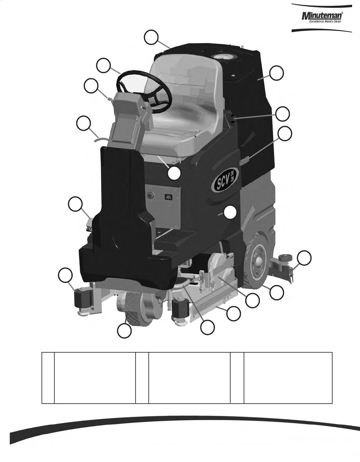
Machine Overview
Front
K
M
A Recovery Tank Lid
B Steering Wheel
C Directional Lever
D Tilt Steering Lever
E Accelerator Pedal
F Roller Bumper
G Front Drive Wheel
H Foot Step
I Side Squeegee
J Scrub Deck
K Solution Tank
L Rear Wheel
M Rear Squeegee
N Seat Adj. Lever
O Safety Latch
P Solution Tank Fill Port
Q Recovery Tank
N
L
I
J
H
G
P
O
Q
C
D
B
A
E
F
Parts and Instruction Manual
Page 4
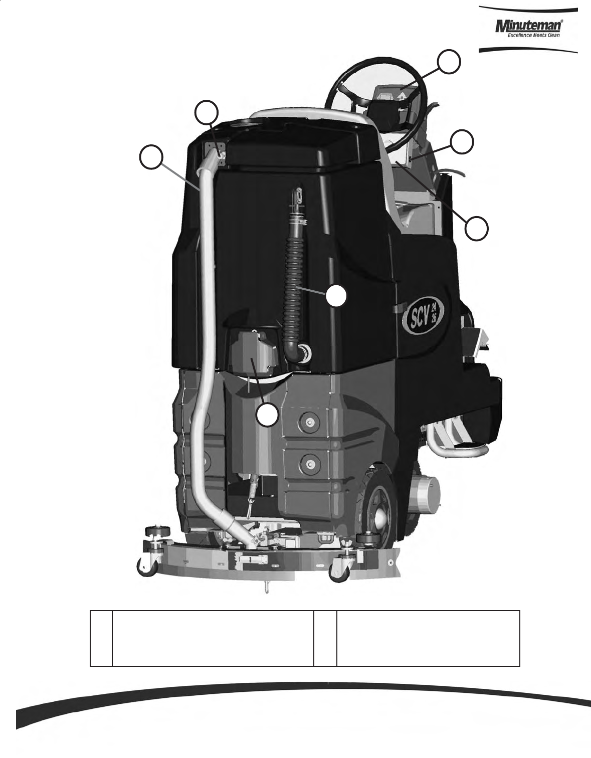
Machine Overview
Rear
A
B
D
F
G
A Recovery Tank Dump Hose
B Off Aisle Wand Hose Connection
C Recovery Hose
D Cleanout
E Upper Control Console
F Horn
G Lower Control Console
C
E
Parts and Instruction Manual
Page 5
1.
When the machine is running in this mode, the machine will perform all operations. This mode can be used
for day-to-day tasks under normal conditions. When the operator sets the directional switch to forward and
activates the accelerator handle, the solution pump will turn on, the brushes will turn on and be lowered to
the floor, as well as the rear squeegee. While operating in this mode, the solution will be dispersed into the
brushes, which will scrub the floor allowing the chemical in the solution to break down the dirt on the floor.
As the machine continues to move forward, the rear squeegee and vacuum system will recover the dirt and
dispensed solution. If the operator stops moving, the machine will automatically raise the scrub deck and
turn off the brushes. If the directional switch is changed to reverse the machine will continue to operate
normally, only the rear squeegee will raise up.
2.
This mode is similar to Regular Scrub. The machine will continue to operate the same was as if it was in
Regular Scrub Mode, only this mode applies more solution and brush pressure is increased. This mode is
used for high traffic areas and areas that have been heavily soiled, but do not require time for the solution
to soak.
Lower Control Console
Regular Scrub Mode
Heavy Scrub Mode
5
1
2
3
4
6

Parts and Instruction Manual
Page 6
3.
When the machine is running in this mode, the machine will perform all operations except dirty solution
recovery. This mode can be used if the floor is heavily soiled and the chemical will need additional time to
emulsify grease and oils that are on the floor. When the operator sets the directional switch to either the
forward or reverse position and activates the accelerator lever, the solution pump will turn on, the brushes will
turn on and be lowered to the floor. While operating in this mode, the solution will be dispersed into the
brushes, which will scrub the floor allowing the chemical in the solution to break down the dirt on the floor. As
the machine continues to move forward or back, the rear squeegee and vacuum system are not on, which
allows the solution to stay on the floor emulsifying the grease and oil. If the operator stops moving in either
direction, the machine will automatically raise the scrub deck and turn off the brushes. After double scrubbing,
the operator should use the vacuum only mode to recover the dirty solution water from the floor.
4.
When the machine is running in this mode, the machine will only lower the rear squeegee and turn on the
vacuum system to recover the dirty solution from the floor. This mode is usually chosen after double scrubbing
to recover the dirty solution but it can also be used to pick up spills. When the operator sets the directional
switch to forward, the rear squeegee will be lowered to the floor as the vacuum turns on, pulling the dirty
solution water from the rear squeegee into the recovery tank. If the operator stops moving forward and sets
the directional switch to reverse, the rear squeegee will retract (protecting it from damage) and the vacuum
motor will turn off after a few seconds. If the operator quits moving in either direction, the machine will
automatically raise the squeegee and turn off the vacuum motor after a few seconds.
5.
When the machine is set in this mode, none of the cleaning functions of the machine will operate. This mode
is only used to transport the machine from one location to another at a faster rate of speed.
6.
This control will adjust the amount of solution that is being dispersed to the floor while in one of the scrub
mode. Adjust control clockwise to increase the amount of solution being dispersed. The solution distribution
range is from zero (0) to a maximum of ¾ GPM.
Double Scrub Mode
Vacuum Only Mode
Transport Mode
Solution Control
Parts and Instruction Manual
Page 7
Upper Control Console
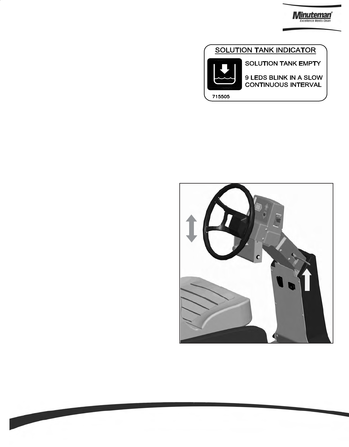
Empty Solution Tank Indicator
Low Battery Indicator
Steering Wheel
The steering wheel is adjustable for operator
comfort by pulling the tilt-steering lever up and
positioning the steering wheel up or down (there
are three possible positions). By pulling on the
tilt-steering lever and positioning the steering
column in an upright fashion, enables the operator
more room when climbing up and down the
machine.
Once the solution tank has become empty the battery
gauge will blink a solid 9 LEDs at a constant interval to
alert the driver that the solution tank needs to be filled.
The battery gauge bar icon will be flashing to signal the operator that the machine is almost out of power.
Once this signal is displayed to the operator, all functions will shut off including the transport mode. The
operator has to turn the key switch OFF and then, ON to reset the machine. The machine then will only have
a few minutes left of reserve power for a short Vacuum only mode to pick up remaining solution on the floor
and Transport power.

Parts and Instruction Manual
Page 8
The SCV is equipped with a power save feature to conserve battery power. If the key switch power is left ON
and none of the controls are activated for a period of fifteen minutes, the SCV automatically goes into “power
down mode” and turns OFF the power to conserve your batteries in case the operator forgets to turn the key
switch off or leaves the machine unattended.
Located on the right side of the operator compartment on the floor is the accelerator pedal. This pedal
controls the propelling speed of the machine. The farther the pedal is pushed down the faster the machine
will travel. As discussed earlier, the directional switch governs the direction of travel the machine will take.
Switching the directional switch with your foot pushed on the pedal will make your machine change directions
(a very slight delay may occur before the direction of travel changes when switching directions on the fly).
The accelerator pedal is interlocked with the seat switch, making machine propulsion not possible without the
operator sitting on the seat.
The ergonomically designed seat is located on top of the solution tank. There is a lever under the seat that
allows the operator to adjust the seat forward or backward for operator comfort. There is an interlock switch
located inside the seat. This makes it impossible to engage the traction drive circuitry without the operator on
the seat. If the operator were to fall off the machine, the traction drive circuitry would turn off.
Located on the right side of the upper control console, this switch controls the direction in which the SCV will
move when the accelerator pedal is activated. There are two arrow located on the upper control console with
LEDs in the center to indicate which mode the SCV is in. The arrow pointing forward with the amber LED
indicates the SCV is in forward mode. The arrow pointing backward with the red LED indicates the SCV is in
reverse mode.
This machine is equipped with an Electro-magnetic brake built-in on the traction drive motor. When the
machine’s power is turned off (using either the key or the emergency button), the E-mag brake is activated
and the traction motor is prevented from moving.
Operation of Controls
Power Save Mode
Accelerator Pedal
Seat
Directional Switch
Parking Brake
Parts and Instruction Manual
Page 9
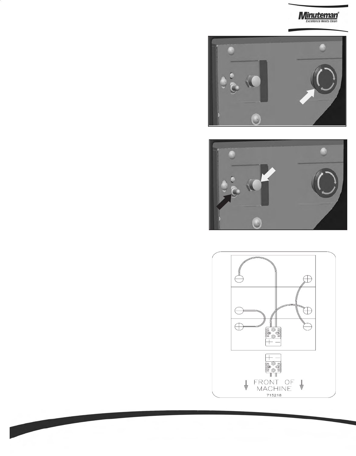
Emergency Disconnect Button
Circuit Breakers
Battery Compartment
The battery compartment is located on the rear of the machine
under the recovery tank. Unlatching the two safety latches on
the side of the machine enables the operator to tilt the recovery
tank and access the batteries for servicing and maintenance
(make sure recovery tank has been drained before tilting). The
battery compartment contains three 12-volt batteries connected
in series. Connect the batteries according to the battery
connection diagram (see diagram). The recommended batteries
are 210Ah (Minuteman P/N 956210).
This button is located in the middle of the electrical panel that
is directly underneath the operator’s seat. When the red
emergency button is pressed, power will be turned off. Use
this button in case of a machine emergency. The red knob
needs to be raised in order to run the machine. To reactivate,
turn the knob as shown by the arrows on the switch and the
button will pop up. All operational settings are retained even
when the power is turned off and on.
The circuit breakers are located next to the emergency
disconnect button. The 6-amp breaker (indicated by white
arrow). protects all auxiliary circuits on the machine (headlights,
horn, and back-up alarm). The 100-amp breaker (indicated
by black arrow) protects the main system circuit (controller).
Each main component is individually protected with an internal
breaker built-in the controller. (See fault code table) and can
be reset by turning the key switch off a few seconds and then
on again. The 100 amp circuit breaker can also be used as a
main power disconnect, this should be used only in case of
emergency. When tripped the breaker removes power from
the main controller and all auxiliary power circuits.
Parts and Instruction Manual
Page 10
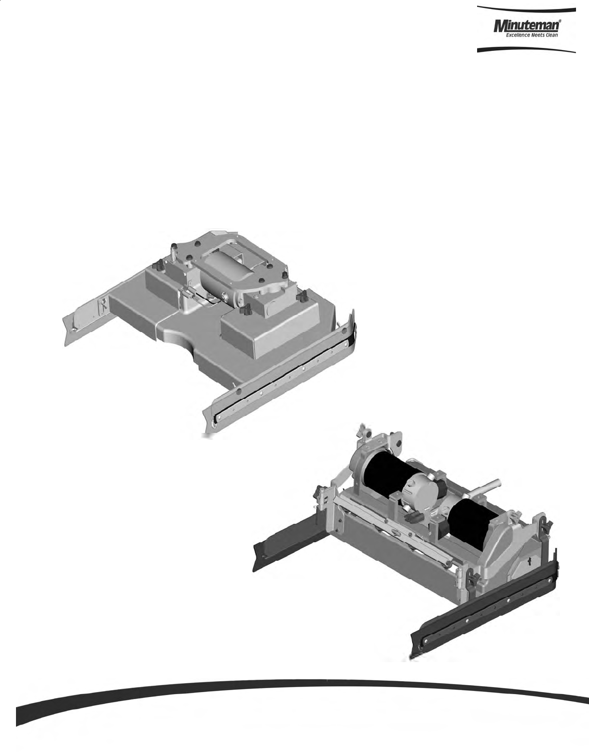
Scrub Deck
Disc Scrub Deck
Cylindrical Scrub Deck
Minuteman offers two deck types (Cylindrical and Disc) to fit your specific needs. The SCV design is very
dynamic wherein the decks are interchangeable in a matter of minutes whenever necessary (removal of four
bolts, and two quick-connects). The cylindrical brush deck has four built-in spray jets to uniformly dispense
cleaning solution on the floor and a wet sweeping debris tray to collect loose objects on the floor. The disc brush
deck dispenses cleaning solution through the center hub and contained within the bristle area for efficient
agitation of cleaning solution to the floor and channeled to the rear of the machine. The disc brushes are also
easily removed and installed with the quick release clamp by using any of the three access doors. Another nice
feature that these scrub decks have is the ability to have uniform brush pressure applied to the floor at all times.
Since the scrub deck brush pressure is computer controlled, it will automatically adjust and compensate to
uneven contours on the floor while maintaining brush pressure.
Parts and Instruction Manual
Page 11
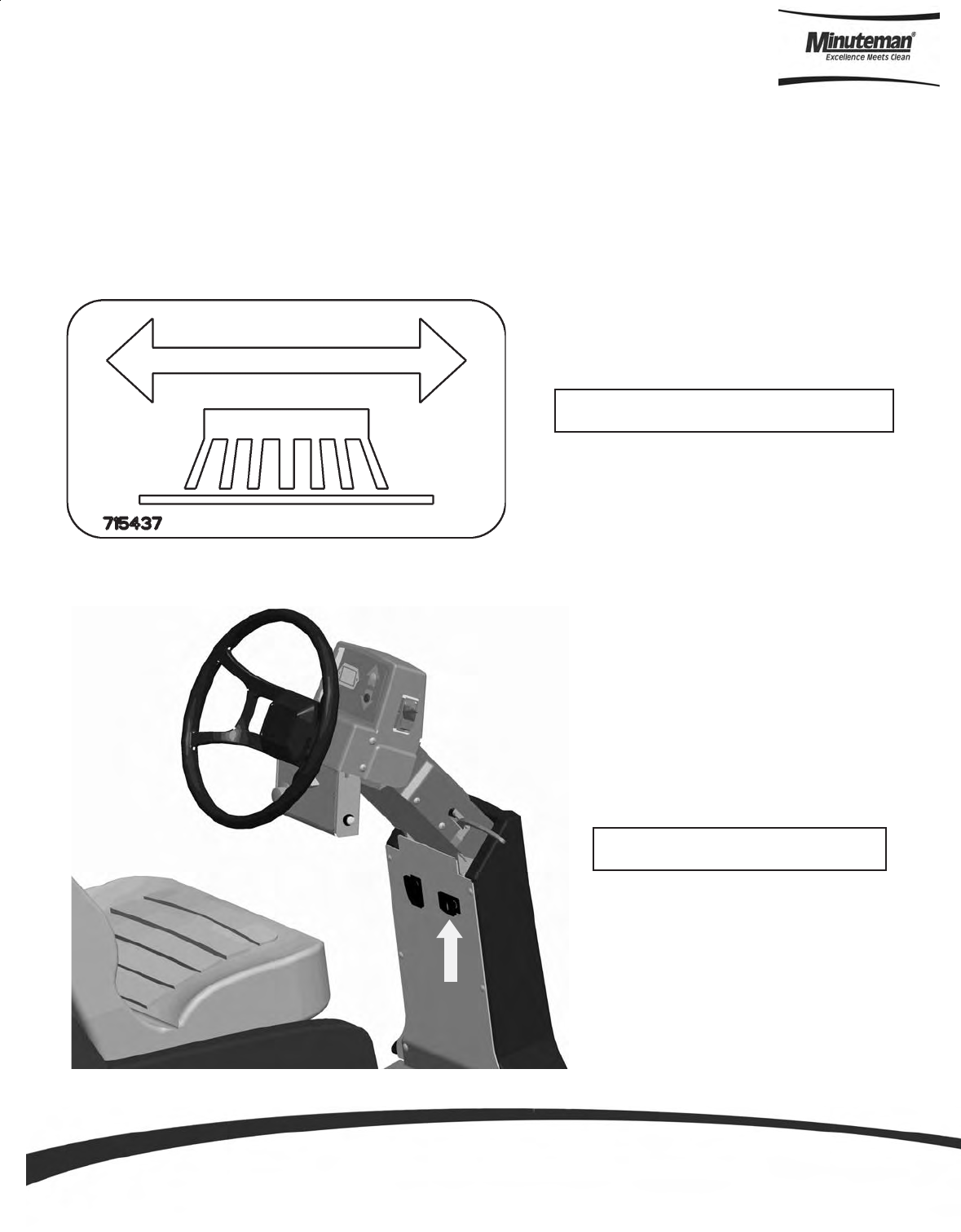
Scrub Deck Shift
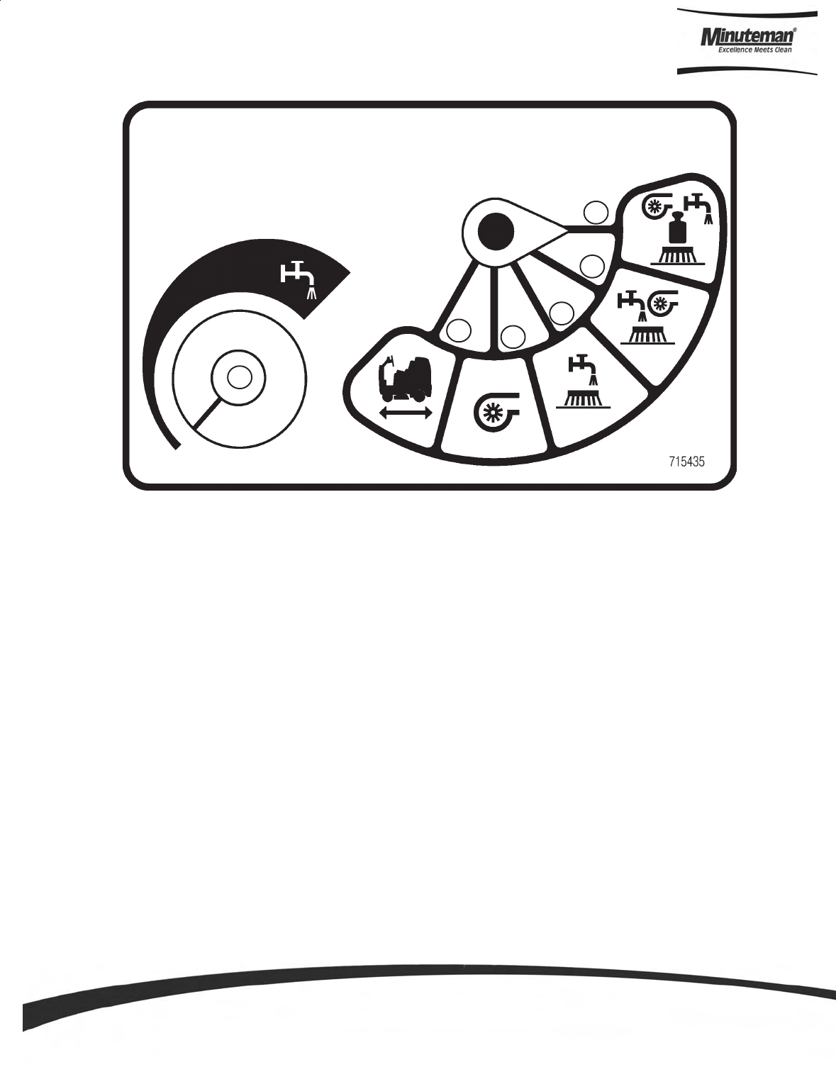
123 Detailed View of 3-Position Switch
Location of Side Shift Switch
The SCV 2426 now incorporates the new side shift feature, which allows the scrub deck to move two inches to
the right to allow users to get into tighter quarters such as under shelving or cleaning close to walls.
The side shift is activated by a lighted three-position rocker switch located directly in front of the drivers seat,
just below the steering wheel (See figure below). The 3 position switch has 3 main functions, return (1), stop
(2) and right offset (3). In order to move the deck right, ‘click’ the switch from the stop position to the right offset
position, you may choose to ‘click’ stop at any time for an arbitrary side shift, otherwise the deck will achieve it’s
full two inch side shift. In order to return the deck to its original position ‘click’ the switch to the return position.
Parts and Instruction Manual
Page 12
8. For cylindrical scrub deck only:
a. Remove knurled knob on side squeegee assembly and
swing out side squeegee to access door.
b. Remove the two access doors (one each end) by removing
the (3) wing nuts.
c. Install the brushes by sliding through the access opening.
(See Figure 1 for correct orientation)
d. Align the notches on the brush with the drive pins on the
hub.
e. Push brush all the way until it bottoms out.
f. Insert access door hub to the other end of brush.
g. Reinstall nuts and tighten.
1. Park the machine on a flat or level surface.
2. Turn the key switch to the ON position and select the trans-
port mode on keyboard.
3. Slide the scrub deck assembly underneath the machine
(follow instructions as described above)
4. Position the scrub deck to align the mounting brackets with
the mounting lugs on the lift linkage.
5. Lower the lift linkage to the floor by pressing the manual
override switch for five seconds.
6. Lower the lift linkage mounting lugs until they barely touch
the scrub deck mounting brackets.
7. Fasten with the four (4) 711242 bolts, 711515 flat washer
and 711546 lock washer.
When installing a cylindrical deck to a machine:
1. Install brushes after the deck has been mounted to avoid flat spots on the brushes.
2. Use a piece of cardboard underneath the deck to prevent scratches to the painted surface when sliding the deck
under the machine.
3. Make sure the scrub deck is oriented correctly with the spray jets towards the front of the machine.
When installing a disc scrub deck to a machine:
1. Install brushes on the scrub deck; this aids the installer in sliding the deck assembly into position.
2. Make sure the scrub deck is oriented correctly with the solution hose tee fitting towards the front of the machine.
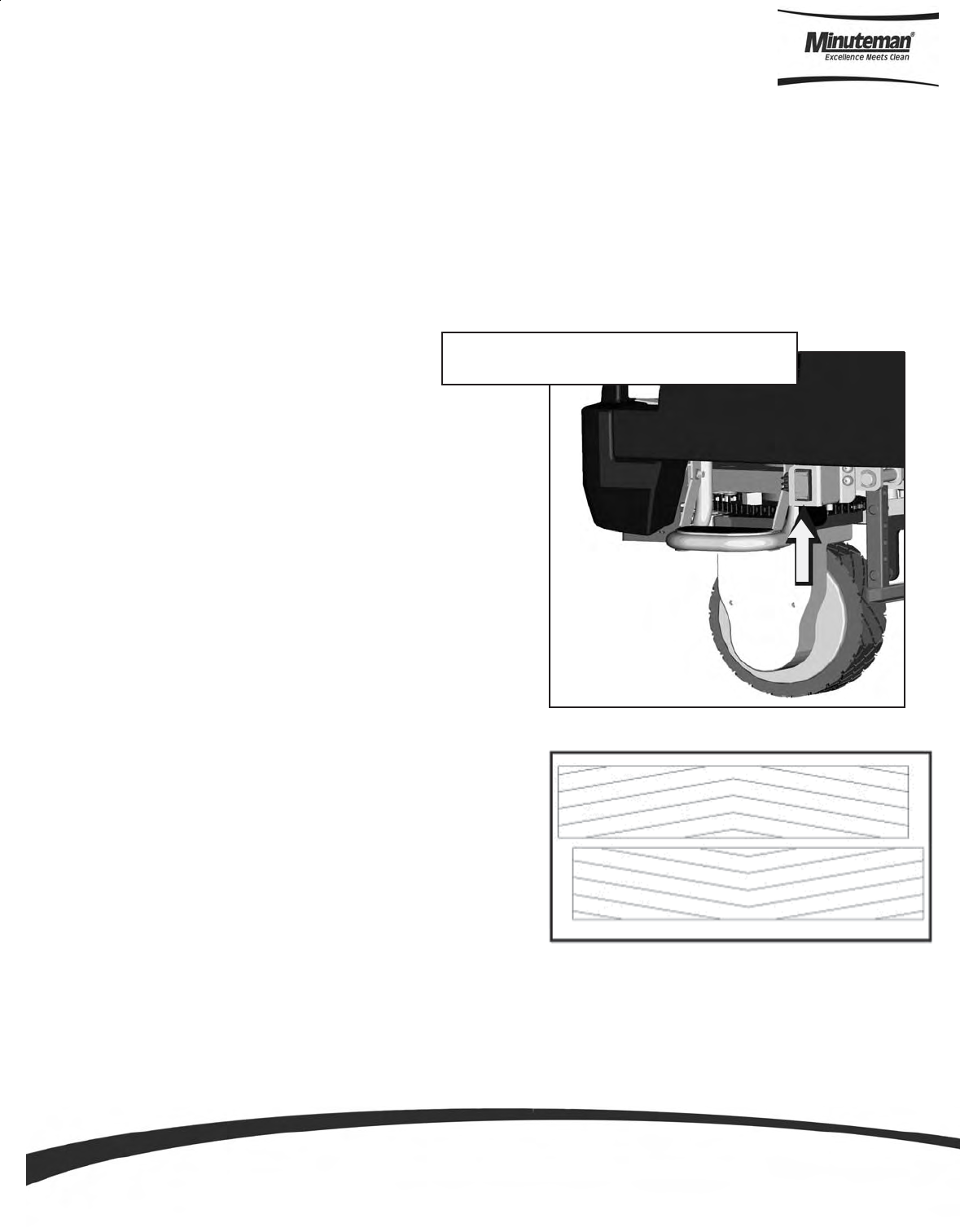
Scrub Deck Installation
Installation Instructions
Manual Overide Switch
Located under front left side of machine
Cylindrical scrub brushes must be installed
with the chevron pattern pointing away from
each other for best water and debis pick up
Parts and Instruction Manual
Page 13
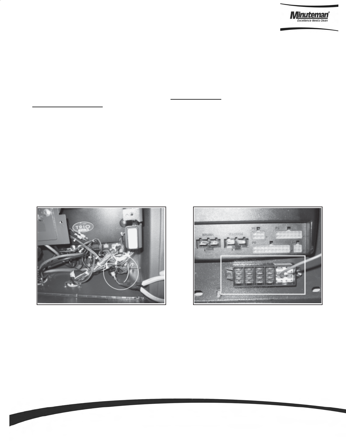
Important Note when Interchanging Scrub Decks
As previously mentioned, the scrub deck brush pressure is computer controlled. However, when interchanging
the two types of decks, an additional step must be taken to ensure that the controller correctly compensates the
pressure for the type of deck that is currently installed.
Inside the main electrical box, beneath the seat there is an Orange/Violet jumper wire (shown disconnected in
Figure 1) that may or may not be connected to the terminal block, depending on the type of scrub deck that was
originally ordered with the machine. When using the Disk Scrub Deck, the wire is disconnected. When using
the Cylindrical Scrub Deck, the wire is connected to the terminal block located in the electrical box, beneath
the TRIO Controller. This terminal block is divided into five sections, each separated by a divider. The four
leftmost sections contain one column each of spade terminals. The section on the right contains two columns of
spade terminals (this section also contains four Red/Black wires, not shown in Figure 2 for clarity). The
Orange/Violet wire must be connected to a spade terminal in the section with two columns when using the
Cylindrical Scrub Deck ONLY!
When switching from the Cylindrical Scrub Deck to the Disk Scrub Deck, be sure to disconnect the Orange/
Violet wire. When switching from the Disk Scrub Deck to the Cylindrical Scrub Deck, connect the Orange/Violet
wire to any available spade terminal in the section that contains two columns (shown in Figure 2) and the Red/
Black wires.
Figure 2
Jumper wire connected to
terminal block
Figure 1
Jumper wire disconnected
Parts and Instruction Manual
Page 14
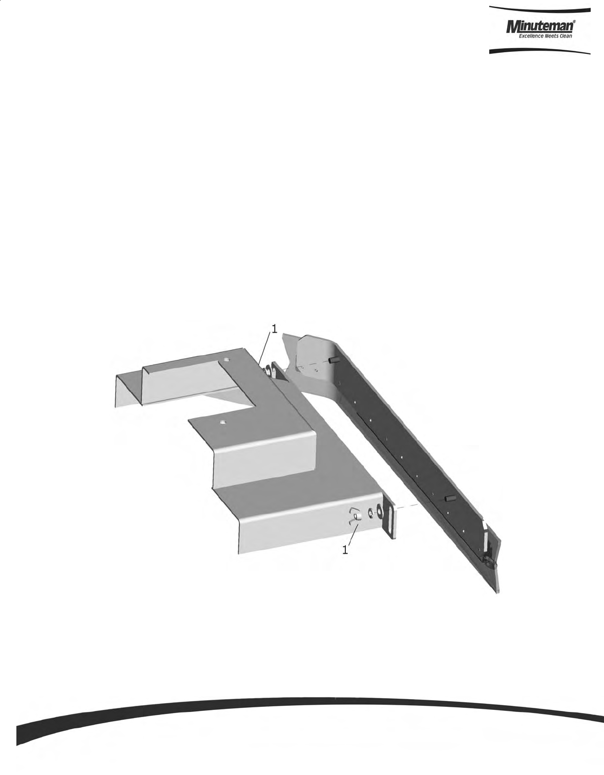
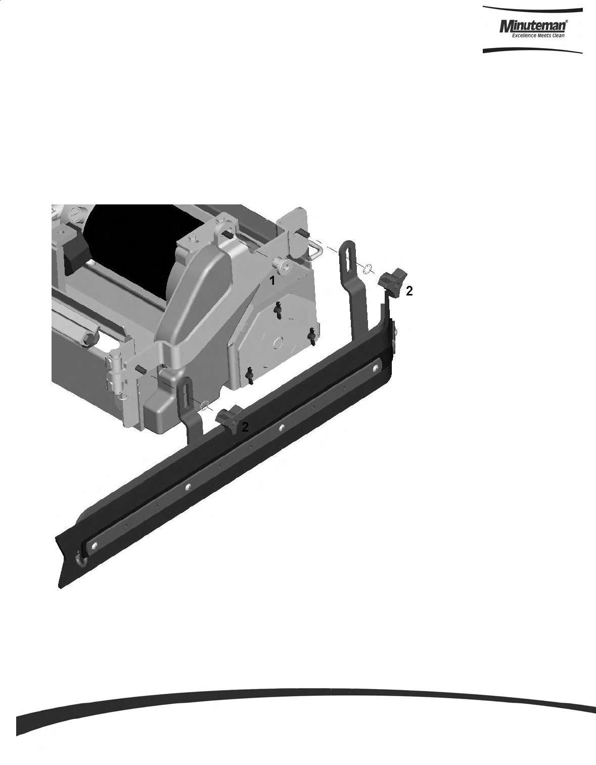
Side Squeegee
The side squeegees (left and right) are attached to the scrub decks. These items channel the dirty solution to
the rear squeegee, helping contain the water within the machine’s cleaning path. These squeegees are raised
when the scrub deck is in the raised position.
The side squeegees are pre-adjusted at the factory. Adjustments may be required when replacing worn
blades or to achieve optimum performance for different floors and conditions.
To adjust the side squeegees, simply loosen the two (front and back) wing nuts (item 1) located behind the side
squeegee blades. Lower the scrub deck by switching to a scrubbing mode and when the brushes start up, turn
off the key switch. At this point the side squeegees should be resting vertically (no deflection) on the floor.
Press down on the side squeegee bracket assembly from each end while making sure that the blade is uniformly
deflected in a 45 degree angle along its whole length. Tighten the wing nuts. Turn the steering wheel all the way
to the left or right and start pushing the machine to the side to inspect the blade deflection and wiping action.
Repeat the steps above until a satisfactory result is obtained. (See the following page for the location of the
fasteners on the cylindrical deck, marked Item 2).
Parts and Instruction Manual
Page 15
Brush Changes on the Cylindrical Deck
In order to change the brushes on the cylindrical deck the side squeegee must be moved in order to
access the brush doors. The cylindrical deck was designed so one can change the brushes without
having to realign the side squeegees. This is accomplished by removing a knurled knob (Item 1) and
swinging the squeegee along the hinge bracket located at the front of the deck, gaining access to the
brushes. Once completed inserting new brushes, replace the brush doors and swing the squeegee back
into place, tightening down the knob (Item 1).
In order to remove or adjust the alignment of the side squeegees on the cylindrical deck, remove the 3
sided knobs (Item 2) and lock washers, and follow the instructions on the previous page.
Parts and Instruction Manual
Page 16
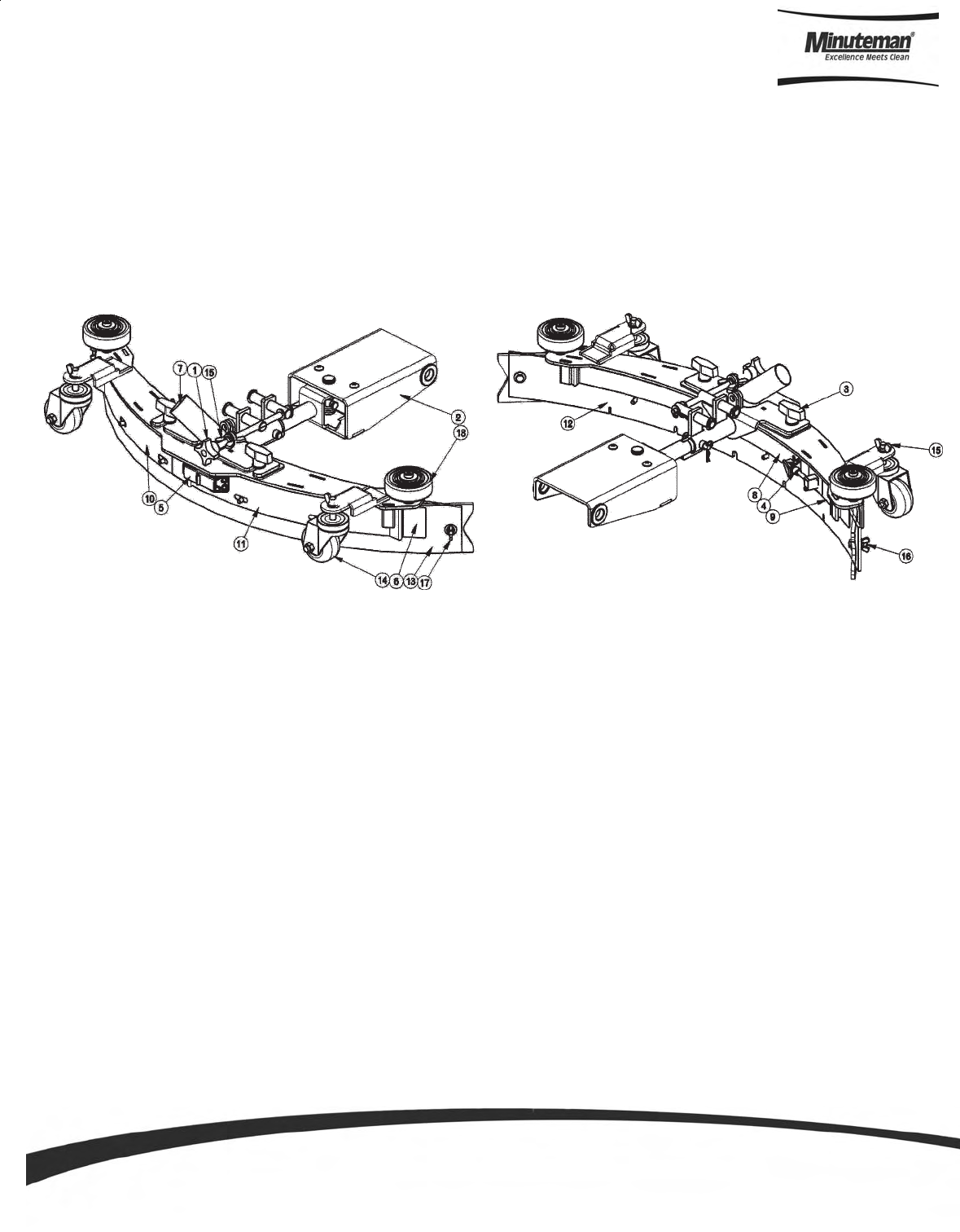
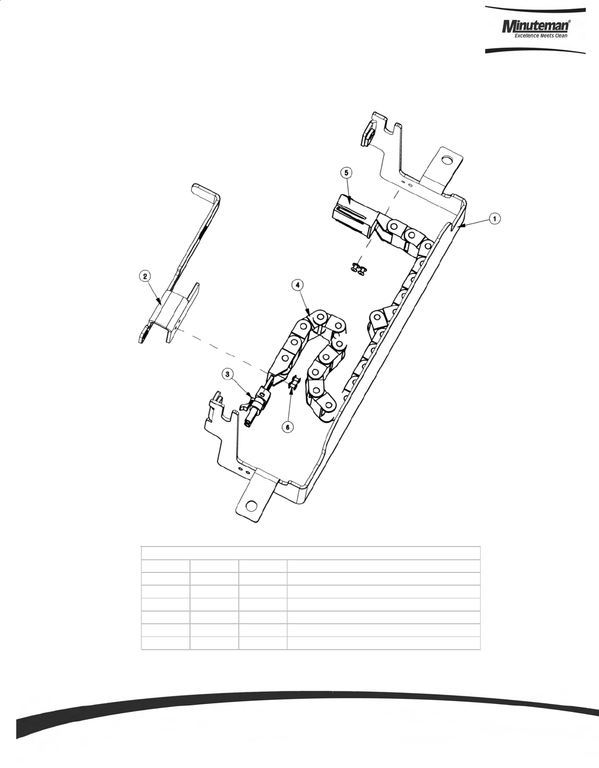
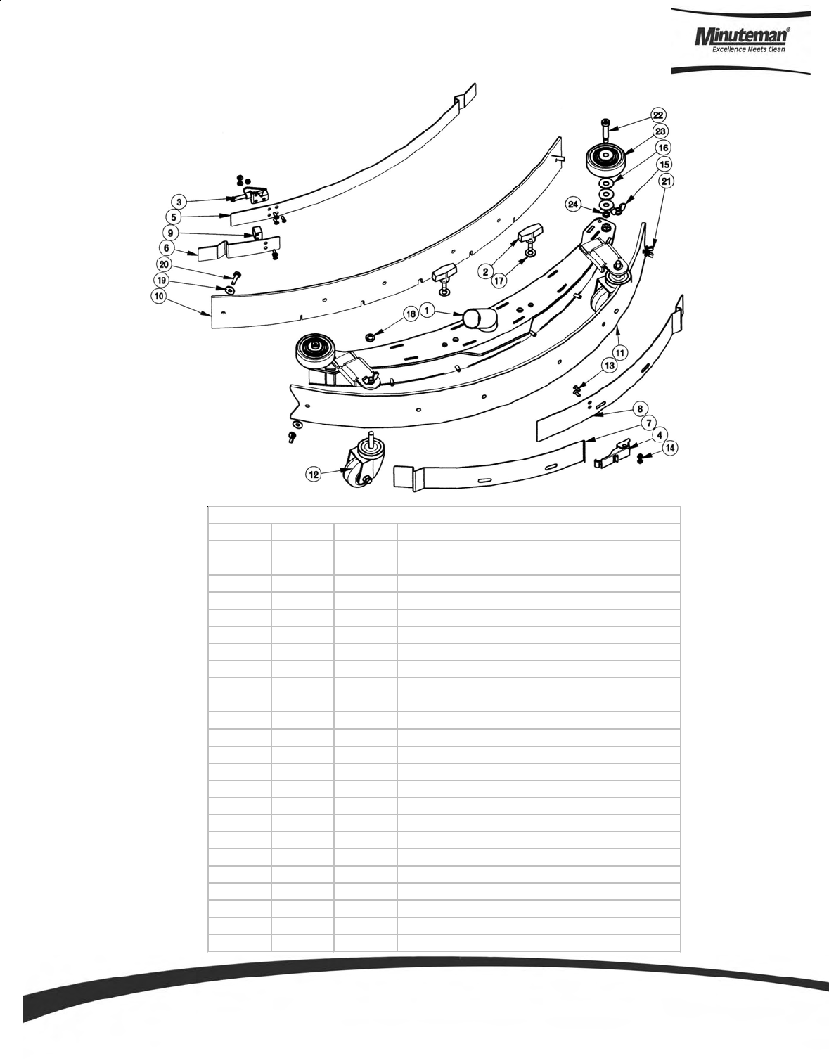
Rear Squeegee
ITEM PART NO. DESCRIPTION
1 241057 KNOB,3/8-16 X 1-3/4 FOUR PRONG.
2 241710 SQUEEGEE LIFT MECH ASSY, SCV 24/26
3 241745 WING BOLT 3/8-16 X 1.00
4 281074 SQUEEGEE TOGGLE CLAMP, 2800
5 281075 SQUEEGEE LATCH, 2800
6 281723 REAR PLATE - SQUEEGEE
7 281727 SQUEEGEE EXTENSION TUBE - WMT
8 281732 STRAP - FRONT CLAMP
9 281734 STRAP - FRONT STOP
10 281736 STRAP - REAR CATCH
11 281738 STRAP - REAR LATCH
12 281763 PB FRONT BLADE,SQUEE GUM RUBBER
13 281764 PB REAR BLADE, SQUEEGEE GUM RUBBER
14 430325 CASTER 3/8"-16 X 1.50"
15 711367 NUT- WING 3/8-16 ST PL
16 711560 SCREW-HH 1/4-20X1.00 NYLON
17 711563 NUT- WING 1/4-20 NYLON
18 808829 WHEEL,TRUCK
The rear squeegee is the main element that acts as the conduit that transfers the spent solution into the
recovery tank. A daily maintenance check of this component is essential to have optimum machine performance.
The rear squeegee assembly is equipped with a universal front blade that allows the operator the option to use
a slotted and a non-slotted side for specific applications. Each blade configuration has two usable edges. The
rear blade however has four usable edges.
The squeegee is pre-adjusted at the factory. Adjustments may be required to get optimum performance
for different floors and conditions.

Parts and Instruction Manual
Page 17
Rear Squeegee Adjustment
1. Ensure that the scrubber is on a relatively flat surface. Turn on the key switch and select the Vacuum only
mode. This lowers the squeegee to the floor and turns the vacuum motor on.
2. Move the scrubber one or two feet forward slowly while someone behind the machine checks the rear
squeegee blade (item 1) for uniform deflection to the floor.
3. If uneven deflection or lay is evident, minor adjustments may be necessary to avoid streaking and uneven
wear on the blade.
4. To correct this, loosen the wing jam nut (item 12) in order to adjust the caster height. If the squeegee blade is
deflecting too much, the casters (item 8) need to be lowered to control the down pressure. Lower the caster
by turning the exposed threaded stem on the caster clockwise. Make the adjustment a few turns at a time.
Repeat step 2.
5. If the blades are not deflecting enough, raise the caster by turning the stem counter-clockwise to adjust the
caster height to allow more down pressure on the squeegee. Repeat step 2.
6. Make sure there is even deflection on the entire length of the rear blade. Adjust the casters and retighten the
wing jam nuts to lock the caster setting in place.
7. Pitch adjustment is necessary if the outer ends on the squeegee blade do not contact the floor and there is too
much deflection in the middle area or if the outer ends are over deflected and there is no contact in the
middle.
8. To adjust the pitch, Repeat step 2.
9. Loosen the two wing nuts (item 5) that lock the pitch angle. Turning the knob (item 3) clockwise or counter-
clockwise controls the forward and backward pitch of the squeegee. Having the rear blades deflected uni-
formly along its entire length is the desired set-up.
10. Repeat step 2 until desired set-up is achieved.
11. In certain applications where a non-slotted front wiper blade (item 18) is needed, detach the rear squeegee
assembly by loosening the two wing bolts (item 16). Unlock the toggle clamp (item 15) on the front squee-
gee to release the front long strap (17) and slide the front short strap (item 13). Flip the blade over to the non-
slotted side. Reattach the straps and lock the clamp back in place.
12. You can also easily replace the rear blade by unlatching the latch (item 4) and removing the two rear straps
(items 1 & 5) by sliding them off the assembly. You can then flip the blade over in order to use a new edge for
Parts and Instruction Manual
Page 18
Off Aisle Wand (Optional)
When the off-aisle wand switch is turned ON, the off-aisle wand switch LED will be lit as well as the battery
gauge will flash to indicate that you are in the off-aisle tool mode. This switch turns on the pump to supply
solution to the wand spray jet and the vacuum motor to recovery the dirty water. When the recovery tank is full,
the vacuum motor and the solution pump automatically shuts off.
The SCV is equipped with a ready-to-use built-in telescoping off-aisle wand system for use in hard to reach
areas. By turning the pump switch ON (located on the control console, see page 11 for illustration) the off-aisle
wand is ready to use in seconds. The wand is also equipped with the patented flip-flop tool that allows the
operator to switch from scrub brush to squeegee tool by just rotating the tool end.
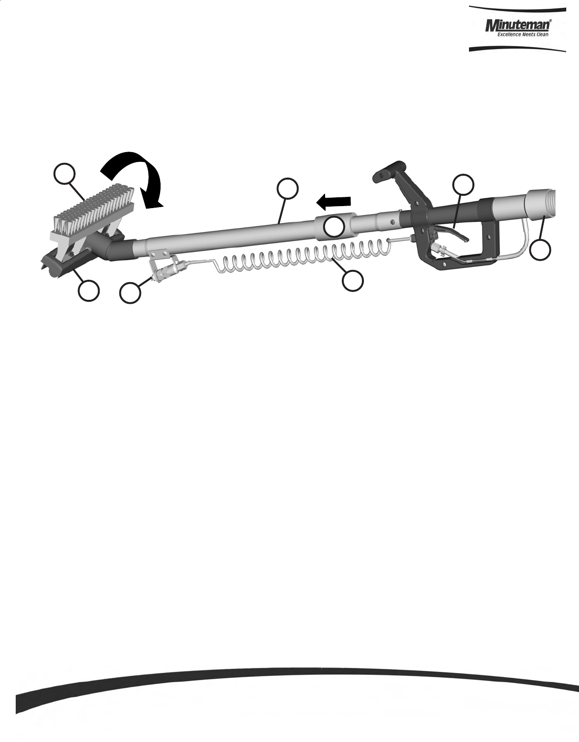
OFF-AISLE WAND TOOL (Optional)
The off-aisle wand tool as described in the previous page is composed of the following items:
1. The recovery hose is connected to the end of the wand on one end and to the diverter assembly (item F)
on the other end. This hose has swivel cuffs on both ends that allow the operator a good range of motion
and the solution hose to be inside the recovery hose.
2. The trigger controls the solution flow to the spray jet. Squeezing the trigger opens an internal valve to
dispense cleaning solution.
3. The coiled solution hose acts as a conduit from the trigger to the spray jet, and allows hose to be extended
along with the wand.
4. The spray jet dispenses the cleaning solution to soak soiled areas that are not accessible to the main
scrub deck.
5. The telescoping wand allows the length to be adjusted for operator comfort and better storage when not
in use.
6. Sliding the wand extender forward (as shown above) extends the wand length during use and retracts the
wand by pulling it back for the storage position.
7. The flip-flop tool gives the operator complete flexibility when changing from the scrub brush mode to
vacuum squeegee mode by simply rotating the end.
1
2
3
4
5
6
7
8
1. Recovery hose
2. Trigger
3. Solution hose
4. Spray jet
5. Telescoping wand
6. Wand extender
7. Vacuum squeegee
8. Scrub brush

Parts and Instruction Manual
Page 19
The SCV Rider
This machine was designed with total operator comfort and ease of use in mind. All machine components have
been designed as a total system to efficiently clean dirty floors. The SCV has four available scrub head types and
sizes to fit specific applications. Please contact your Minuteman representative for specific recommendations for
the correct scrub head type, size, and brush type and chemical applications.
Before using the machine, always perform the following steps to ensure proper machine operation.
•Check under the machine for leaks.
•Check the rear and side squeegees for wear and damage.
•Check the steering for proper operation.
•Check the solution and recovery tanks.
After using the machine, always perform the following steps:
•Check the battery charge level. Charge batteries if necessary. When charging batteries, extra precaution is
required:
Battery acid can cause burns.
When working on or around batteries, always wear protective clothing and safety glasses.
Remove metal jewelry. Do not lay tools or metal objects on top of the batteries.
Charging batteries generate explosive gasses.
DO NOT CHARGE BATTERIES WHEN OPEN FLAMES OR SPARKS ARE PRESENT. DO NOT SMOKE.
Make sure the charger is turned off before disconnecting it from the batteries.
Charge the batteries in a well-ventilated area.
Fluid levels should be checked before and after charging and maintained at the proper levels. If low,
add water until the metal plates are covered.
If the machine is not used for an extended period of time, batteries should be kept fully charged with
a boost charge once a week.
•Check for wire, string, or twine wrapped around the scrub brushes.
•Check the squeegees for wear and damage.
•Check the rear squeegee suction hose and off-aisle wand hose for obstructions.
•Empty and clean the debris box (cylindrical systems only).
•Drain and clean the recovery tank.
•Check under the machine for leaks.
•Check the service records to determine maintenance requirements.
WARNING!
•Be sure you understand the machine controls and their functions.
•While on ramps or inclines, avoid sudden stops when tanks are filled.
•Avoid abrupt sharp turns. Slow down driving speed when going downhill.
•Always drive up when cleaning ramps.

Parts and Instruction Manual
Page 20
Machine Operation
Follow the instructions in preparing the machine for use as described in this manual.
1. While seated on the machine, adjust the steering wheel to desired position using the tilt lever.
2. Turn the Key switch ON (I). The Battery Gauge will light up and display the Remaining Battery Life.
3. Select one of the five available Modes on the Control Console for the required task. Refer to the Main
Keyboard section of this manual for a complete description of the functions.
4. Determine the direction you need to travel by selecting forward or reverse on the Directional Switch.
Vary the pressure exerted on the accelerator pedal to propel the machine at the desired speed.
5. Stepping on the Accelerator Pedal turns on the Transport, Brushes, Water Flow, Vacuum and lowers the
Rear Squeegee accordingly to the Mode selected. If the operator steps on the accelerator pedal before, or
turns the key switch “ON” at the same time, the machine will not move as a safety precaution. Simply
remove your foot off the pedal and step on the pedal again to drive the machine. Please refer to the Main
Keyboard section of this manual for a complete description of the functions.
6. When Reverse is selected on the Directional Switch, the Back-up Alarm will be activated and the Rear
Squeegee automatically is raised when you step on the accelerator pedal. However, the Scrub brushes will
continue to rotate and solution will continue to flow.
7. Start scrubbing by driving the machine forward in a straight line at 3/4 speed and overlap each path by 2 to
3 inches. Adjust your speed; brush pressure and solution flow according to the condition of the floor.
CAUTION!
To avoid any damage to the floor, keep the machine moving when the brushes are turned on.
8. When scrubbing, check behind the machine occasionally to see that all the dirty water is being picked up. If
streaking occurs, your Recovery Tank may be full, the Squeegee hose may be clogged, or the Rear
Squeegee may require some adjustment.
9. Make the necessary adjustments on the Rear and Side Squeegees if streaking occurs both in straight
paths and in turns. Pleas refer to the Rear Squeegee and Side Squeegee section of this manual before
making any adjustments.
10. In cases where the floors are extremely soiled and dirty, the Double Scrub mode may be needed. As
described in the Main Keyboard section of this manual, this mode allows the operator to be able to scrub an
area without recovering the cleaning solution with the rear squeegee in the raised position (no vacuum) to
allow the cleaning solution a longer time to loosen dirt. A final pass on the same area is made with the mode
switched over to either Full Function or Vacuum Only mode to recover the dirty water.
11. The recovery tank has a safeguard for overflow protection to guard against water from entering the vacuum
system when the recovery tank is full. The vacuum will stay ON for 15 seconds and then shut-off automati-
cally. A ball float shut-off system has also been integrated into the Recovery Tank. When the dirty water
reaches a certain level, the ball gets suctioned into the vacuum manifold and blocks the airflow thus, pre-
venting the machine from picking up more liquid. When this happens, the operator is then required to stop
scrubbing and empty the recovery tank.
12. To stop scrubbing, select the Transport mode. This will automatically stop the Solution Flow, raise the
Scrub deck, and raise the Rear squeegee (there is a 15 second delay for the vacuum motor).
13. Drive the SCV to a designated dirty water disposal area and empty the Recovery tank. To empty, remove the
Drain hose from its storage hanger. Unscrew the plug and hold the hose end above the water level in the
tank to avoid sudden, uncontrolled flow of dirty water. With the plug completely off, carefully direct the water
flow to the desired drain. Reinsert the plug and tighten and return to its storage hanger.
14. The recovery tank should be rinsed out to remove solids in the tank. Open the Cleanout cap to remove the
Stopper plug. Tilt the recovery tank (similar to accessing the batteries) and clean the sludge that has
settled in the sump area by either back flushing or by scraping it out.

Parts and Instruction Manual
Page 21
15. Be sure to tightly secure the Stopper plug and cleanout cap before continuing to operate the scrubber.
16. Refill the solution tank and continue scrubbing until the job is done or when the machine runs out of power.
17. The battery gauge bar icon will flash to signal the operator that the machine is almost out of power. Once
this signal is displayed to the operator, all functions will shut off (brush will turn off and the scrub deck will
raise up, water flow will cease, the rear squeegee will raise up and the vacuum motor will turn off) including
the transport mode. The operator has to turn the key switch OFF and then, ON to reset the machine. The
machine then will only have a few minutes left of reserve power for a short Vacuum only mode to pick up
remaining solution on the floor and Transport power to drive to the battery recharging station.
1. When finished scrubbing, select the Transport mode, all functions will shut off (brush will turn off and the
scrub deck will raise up, water flow will cease, the rear squeegee will raise up and the vacuum motor will turn
off). Drive the machine to a service area for daily maintenance and review items that may need service.
2. Empty the solution tank, by directly opening the Garden hose valve underneath the machine into a drain on
the floor or use a garden hose and attach it to the fitting to remotely drain the solution tank. Rinse the tank with
clean water to prevent any build-up of dried up chemicals that could cause clogging in the plumbing.
3. Empty the recovery tank as described on line 15 and 16.
4. Remove the brushes or pad holders and rinse them in warm water and hang to dry.
5. Remove the rear squeegee, rinse with warm water and reinstall after cleaning.
6. Remove the side squeegees, rinse with warm water and remove the debris box (cylindrical system only)
and clean thoroughly. The debris box can be removed from either side of the machine by tilting the box up
and away from the housing and then pulling it out. Reinstall the debris box and side squeegees after clean-
ing.
7. Check the maintenance schedule on the next page and perform any required maintenance before storing
the machine.
8. Store the machine indoors in a clean dry place. Keep from freezing. Leave solution and recovery tank lids
open for ventilation to prevent odor build-up.
9. Turn Key switch OFF (O) and remove key.
After Use

Parts and Instruction Manual
Page 22
•Have Minuteman check the vacuum motor carbon motor brushes once a year or after 300 operating hours.
The brush motor carbon brushes should be checked every 500 hours or once a year.
NOTE: Refer to the Service Manual for more detail on maintenance and service repairs.
Regularly scheduled lubrication of certain machine parts should be performed to insure trouble-free opera-
tion of the machine. Apply a generous amount of grease into the fittings on the machine until grease seeps
out around the bearings.
The grease points are listed below:
Rear squeegee caster wheel axle (2)
Rear squeegee caster wheel stem (2)
Side squeegee caster wheel axle (2)
Side squeegee caster wheel stem (2)
Steering wheel chain sprockets and idlers
Apply lubricant or light machine oil to lubricate the:
Rear squeegee general pivot points
Side squeegee general pivot points
Scrub deck linkages
Drive wheel assembly seals.
Maintenance Schedule
Lubricating the Machine
Daily Weekly Monthly Yearly
Charge Batteries
Check Each Battery
Cell(s) Water Level Lubrication –
Grease Fittings,
chains, etc.
Check Carbon
Brushes
Check/Clean Tanks
& Hoses Inspect Scrub
Housing Skirts
Check/Clean/Rotate
the Brushes/Pads Inspect and Clean
Solution Filter
Check/Clean the
Squeegee Check Foot/Parking
Brake for Wear &
Adjustment
Check/Clean
Vacuum Shut-Off
Float
Clean Spray jets on
Cylindrical System
Check/Clean the
Vacuum Motor
Foam Filter
Clean Hopper on
Cylindrical System

Parts and Instruction Manual
Page 23
Problem Possible Cause Remedy
Worn or torn squeegee
blades Rotate or replace blades
Squeegee out of adjustment Adjust so blades touch floor
evenly across entire width
Recovery tank full Empty recovery tank
Recovery tank drain hose
leak Secure drain hose cap or
replace
Recovery tank lid gasket leak Replace gasket lid cover
properly
Debris caught in squeegee Clean squeegee
Vacuum hose clogged Remove debris and flush
hose
Using too much solution Adjust solution control
valves
Poor water pick-up
Vacuum hose to squeegee or
recovery tank disconnected to
squeegee or damaged
Reconnect or replace
squeegee hose
Worn brushes Rotate or replace brushes
Wrong brush or cleaning
chemical Consult Minuteman
Debris caught on scrub
brushes Remove debris
Moving machine too fast Slow down
Poor scrubbing
performance
Low battery charge Recharge batteries
Solution tank empty Fill solution tank
Recovery tank full Empty recovery tank
Solution lines, valves, filter or
spray jets clogged Flush lines, and clean
solution filter and spray jets.
Inadequate solution
flow or no solution to
the floor
Solution solenoid valve Clean or replace valve
Emergency stop switch
tripped Activate switch by turning as
indicated by arrows.
Operator seat safety switch Operator has to be seated.
Check for open circuit and
replace
Main system controller Check error fault codes
Machine does not run
Tripped 100 amp circuit
breaker Check for electrical short
circuit
Reset machine: Reset
breaker and turn key switch
off and restart.
General Machine Troubleshooting

Parts and Instruction Manual
Page 24
Drive system speed controller.
Check error fault codes
(See service manual)
Reset machine: Turn key
switch off and restart.
No FWD/REV drive
Emergency stop switch tripped Activate switch by turning as
indicated by arrows.
Recovery tank full Empty recovery tank
Excessive foaming in recovery
tank. Empty recovery tank.
Use less or change chemical.
Use defoaming agent.
Vacuum motor does
not turn on Five LEDs flashing on Battery
Guage Check for motor overload.
Reset machine: Turn key
switch off and restart.
Debris box full Empty and clean debris box
Brushes worn Replace brushes
Poor sweeping
performance
(Cylindrical System) Bristles have taken a set Rotate brushes
Solution tank empty Refill solution tank
Solution tank empty
indicator light on Faulty float switch Replace float switch
Recovery tank. full Empty recovery tank.
Float switch full of debris Clean float switch.
Recovery tank full
indicator light on Faulty float switch Replace float switch

Parts and Instruction Manual
Page 25
SCV 24/26 Fault / Diagnostic Codes
Parts and Instruction Manual
Page 26
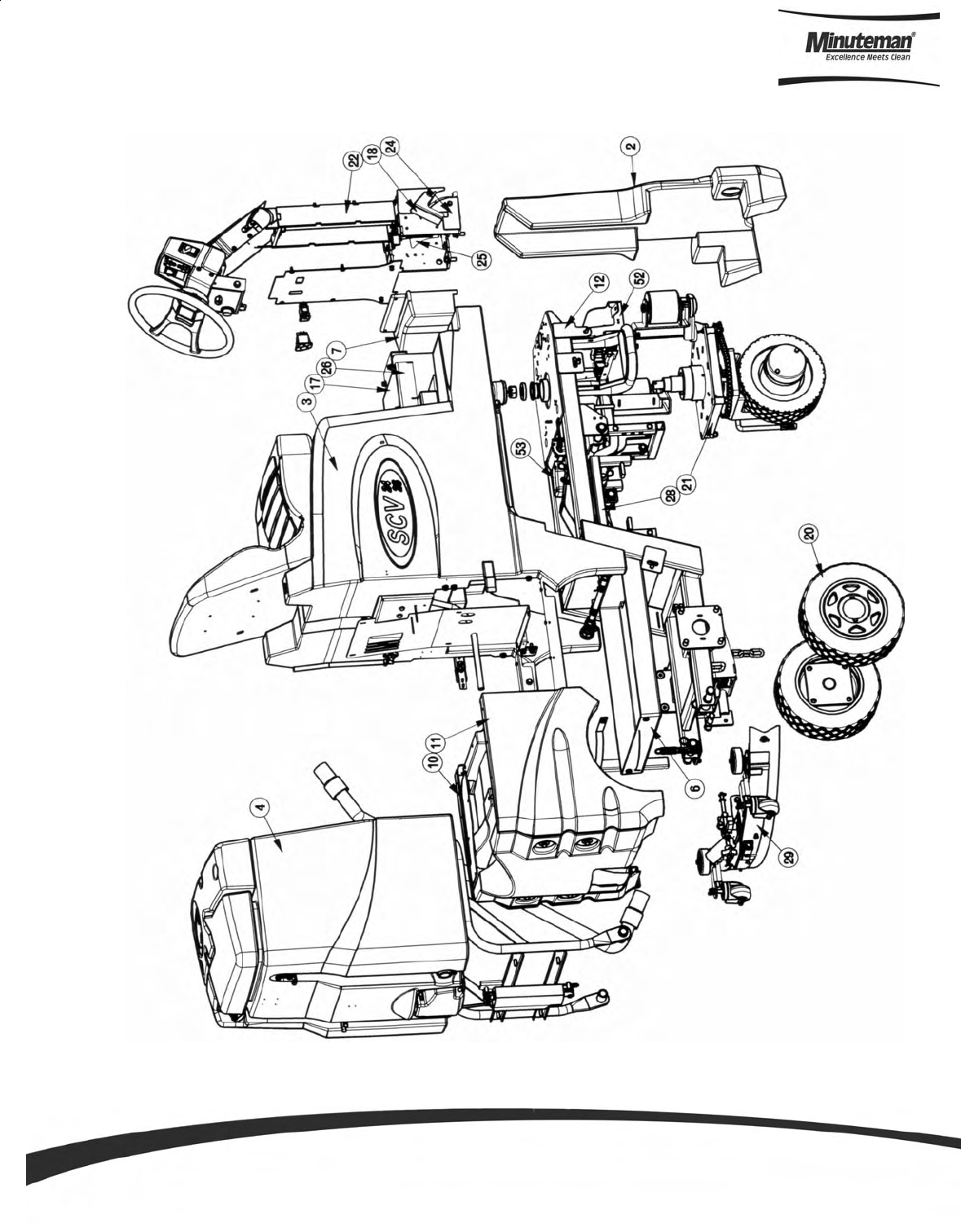
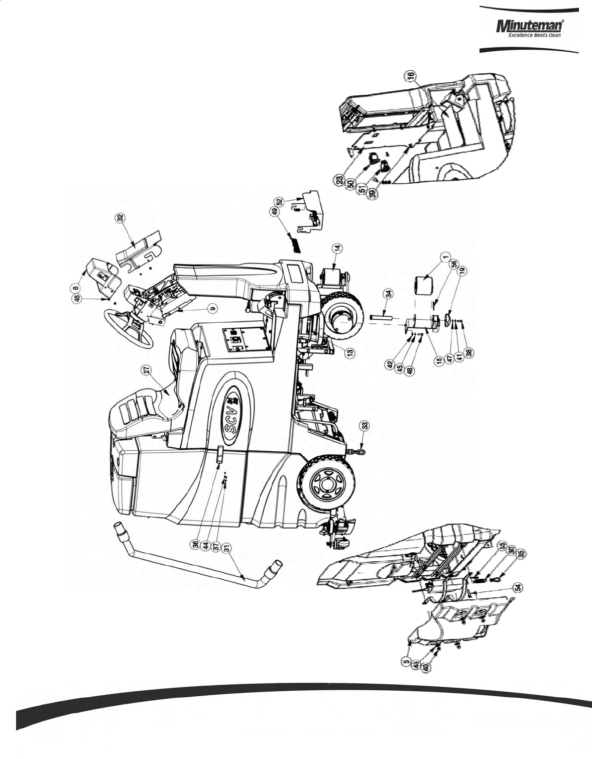
Exploded Views
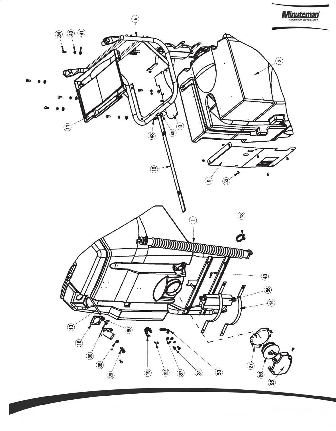
Main Assembly I
Parts and Instruction Manual
Page 27
Main Assembly II

Parts and Instruction Manual
Page 28
ITEM PART NO. REQ'D DESCRIPTION
1 66-436-A 2 RUBBER ROLLER
2 241001 1 BUMPER, FRONT SCV24
3 241012 1 SOLUTION TANK ASSY w/OAW, SCV 24/26
4 241013 1 RECOVERY TANK ASSEMBLY, SCV 24/26
5 241023 1 REAR BATTERY COVER, SCV 24/26
6 241024 1 BATTERY BOX, SCV24/26
7 241025 1 BOTTOM STEERING COLUMN COVER, SCV 24/26
8 241028 1 MAIN STEERING COVER, SCV 24/26
9 241030 1 STEERING COVER BOTTOM, SCV 24/26
10 241045 1 LH BATTERY PANEL ASSY, SCV 24/26
11 241046 1 RH SIDE PANEL ASSY, SCV 24/26
12 241101 1 MAIN FRAME WELDMENT, SCV 24/26
13 241117 2 FRONT FOOT STEP ANTISKID, SCV 24
14 241133 2 ROLLER/ANTI-TIP BRACKET ASSEMBLY, SCV 24/26
15 241134 2 ROLLER/ANTI-TIP BRACKET WELDMENT, SCV24/26
16 241138 1 FOOT REST ANTISKID,SCV 24/26 RH
17 241139 1 FLOOR PANEL ANTISKID, SCV 24/26
18 241143 1 ADJUSTABLE PEDAL ANTISKID, SCV 24/26
19 241151 2 ANTI-TIP PAD, SCV 24/26
20 241201 2 REAR WHEEL ASSY, SCV 24/26
21 241251 1 FRONT DRIVE ASSEMBLY (10"), SCV 24/26
22 241301 1 STEERING ASSEMBLY, SCV 24/26
23 241323 1 REAR STEERING COLUMN COVER, SCV 24/26
24 241324 1 RIGHT FOOT PEDAL AREA COVER, SCV 24/26
25 241325 1 LEFT FOOT PEDAL AREA COVER, SCV 24/26
26 241351 1 FLOOR PANEL WELDMENT, SCV 24/26
27 241365 1 SEAT SUB ASSEMBLY, SCV 24/26
28 241451 1 LINKAGE ASSY W /ACTUATOR, SCV 24/26
29 241701 1 SQUEEGEE MECH ASSY
30 241970 1 SPRING-EXT .75 O.D. X 3.0 F.L. CLOSED ENDS
31 281078 1 HOSE ASSY - SQUEEGEE, SCV 28/32
32 282029 1 STEERING COVER, TOP
33 320996 1 STATIC GROUNDING CHAIN
34 360017 4 3/4" X 4.50 CLEVIS PIN
35 430103 1 SPRING HOOK 2450S
36 450207 2 LATCH, SOFT #C7-10
37 710328 10 SCR-MC 8-32 X .37 ST PL - ROUND HEAD
38 710825 2 SCR-SC 1/4-20 X .75 ST PL
39 711160 6 #10 X 5/8 HI-LO
40 711353 4 NUT, ACORN 5/16-18
41 711504 2 WSR-FLAT 1/4 ID SS
42 711506 6 WSR-FLT .344 X .690 X .062 STL ZINC
43 711507 4 WSR-FLAT .37 X 1.12 X .06
44 711542 10 WSR-HELICAL #8
45 711545 6 WSR-HELICAL 5/16
46 712540 12 SCR-MC TR HD 10-24 X .37 SS
47 712758 2 WSR-HELICAL 1/4 SS
48 713026 2 BLT-HH 5/16-18 X 3/4 #5
49 715385 1 MINUTEMAN LOGO 1.4 X 9.6
50 748201 1 SWITCH, SPDT ILLUM EA DIRECTION
51 748202 1 SWITCH, SPST ILLUM
52 748208 1 CABLE ASSY, DRIVE MOTOR SCV 2426
53 748213-1 1 ACTUATOR, W/WEATHER PACK SCV SQUEEGEE
54 831965 1 3/8 x 1.63" CLEVIS PIN
55 833374 1 PIN, HAIRPIN COTTER 3/8
56 3400661 2 PIN-COTTER 5/8 RUE-RING
BILL OF MATERIAL
Main Assembly BOM (See Main Assembly I & II)
Parts and Instruction Manual
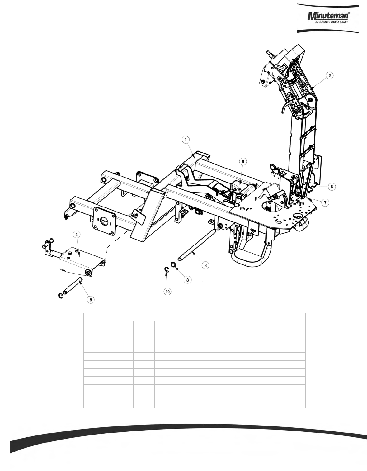
Page 29
Mainframe Assembly
ITEM PART NO. REQ'D DESCRIPTION
1 241101 1 MAIN FRAME WELDMENT, SCV 24/26
2 241301 1 STEERING ASSEMBLY, SCV 24/26
3 241480 1 LINKAGE ATTACHMENT SHAFT, SCV 24/26
4 241710 1 SQUEEGEE LIFT MECH ASSY, SCV 24/26
5 320909 1 LIFT MECH ASSY PIVOT SHAFT
6 711242 6 BLT-HEX 3/8 -16X1.00 ZP
7 711515 6 WSR-FLAT .406 X .812 X .0625
8 711583 2 WSR-WAVE .78 X 1.00 X .02
9 748213-1 1 ACTUATOR, W/WEATHER PACK SCV SQUEEGEE
10 809148 4 RETAINING RING - "E" TYPE EXT .75
BILL OF MATERIAL
Parts and Instruction Manual
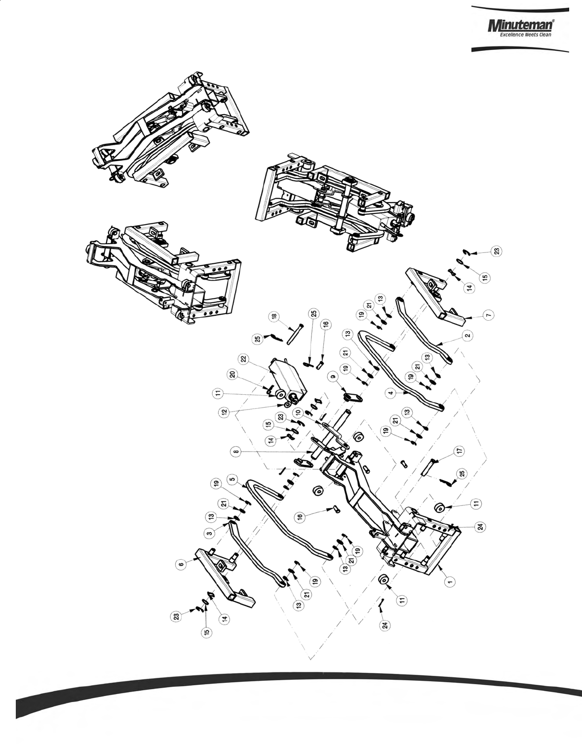
Page 30
Linkage Assembly

Parts and Instruction Manual
Page 31
ITEM PART NO. REQ'D DESCRIPTION
1 241452 1 FIXED PIVOT WELDMENT, SCV 24/26
2 241462 1 LEFT UPPER LINK ASSEMBLY, SCV 24/26
3 241464 1 RIGHT UPPER LINK ASSEMBLY, SCV 24/26
4 241465 1 LEFT LOWER LINK ASSEMBLY, SCV 24/26
5 241467 1 RIGHT LOWER LINK ASSEMBLY, SCV 24/26
6 241468 1 LEFT LIFT WELDMENT W/BUSHING, SCV 24/26
7 241470 1 RIGHT LIFT WELDMENT W/BUSHING, SCV 24/26
8 241472 1 LINK ATTACHMENT SHAFT, SCV 24/26
9 241476 2 DECK LIFT LINK WELDMENT, SCV 24/26
10 241479 1 DECK LIFT CRANK WELDMENT, SCV 24/26
11 241485 5 POLYURETHANE ROLLER, SCV 24/26
12 711508 1 WSR-FLAT .44X 1.0X.08)
13 711524 8 WSR-WAVE .52 X .87 X .01
14 711583 4 WSR-WAVE .78 X 1.00 X .02
15 711588 4 WSR-FLAT .75X1.00X.025
16 711668 5 CLEVIS PIN, 3/8X1 11-141
17 711669 1 CLEVIS PIN .5 X 2.5
18 711681 1 PIN CLEVIS, 3/8 X 3-1/4 ZP
19 711713 8 RETAINING RING - "E" TYPE EXT .500
20 711808 1 COTTER PIN-HAIR #13
21 712310 8 WSR- FLAT .52 X .87 X .06 PL
22 740822-1 1 LINAK ACTUATOR, 100MM STROKE, 75 W/TERMINALS
23 809148 4 RETAINING RING - "E" TYPE EXT .75
24 809311 4 PIN-COTTER 7/64 DIA X 1
25 833374 3 PIN, HAIRPIN COTTER 3/8
BILL OF MATERIAL - 241451
Linkage Assembly BOM
Parts and Instruction Manual
Page 32
Front Drive Assembly
ITEM PART NO. REQ'D DESCRIPTION
1 241252 1 SPINDLE WELDMENT, SCV 24/26
2 241257 1 FRONT DRIVE W/ BEARING ASS'Y, SCV 24/26
3 241265 1 GEAR RESEARCH CHASSIS DRIVE 10" ASSEMBLY
4 281054 1 CHAIN, STEERING No. 40, 27.5"
5 281254 1 STEERING DISC WMT
6 281268 1 SPROCKET-RC #40, 10 TEETH, 3/4" BORE
7 281285 1 IDLER ASSY, FRONT DRIVE
8 383077 1 BEARING CONE (LM104949)
9 383250 1 GREASE CAP
10 383277 1 KEY WOODRUFF 3/16 X 3/4
11 383364 1 THRUST WASHER
12 710858 4 SCR-SC 3/8-16 X 1.00
13 711546 3 WSR-HELICAL 3/8
14 711588 1 WSR-FLAT .75X1.00X.025
15 711807 1 COTTER PIN .12 X 1.75
16 712113 1 CASTLE NUT
17 713043 3 BLT-HH 3/8-16 X 1 1/4 #5
18 809148 1 RETAINING RING - "E" TYPE EXT .75
19 809247 3 STEERING PLATE SPACER
BILL OF MATERIAL - 241251
Parts and Instruction Manual
Page 33
ITEM PART NO. REQ'D DESCRIPTION
1 241081 1 FIXED WIRE MTG BRKT, SCV 24/26
2 241082 1 MOVING WIRE BRACKET, SCV 24/26
3 748020 1 CONNECTOR, PACKARD 2 COND MALE
4 748207 1 CABLE GUIDE, SCV 24/26
5 748221 1 WIRE ASSY, TRACTION MOTOR SCV 24
6 827666 4 RIVET-POP
BILL OF MATERIAL - 748208
Drive Cable Guide Assembly
Parts and Instruction Manual
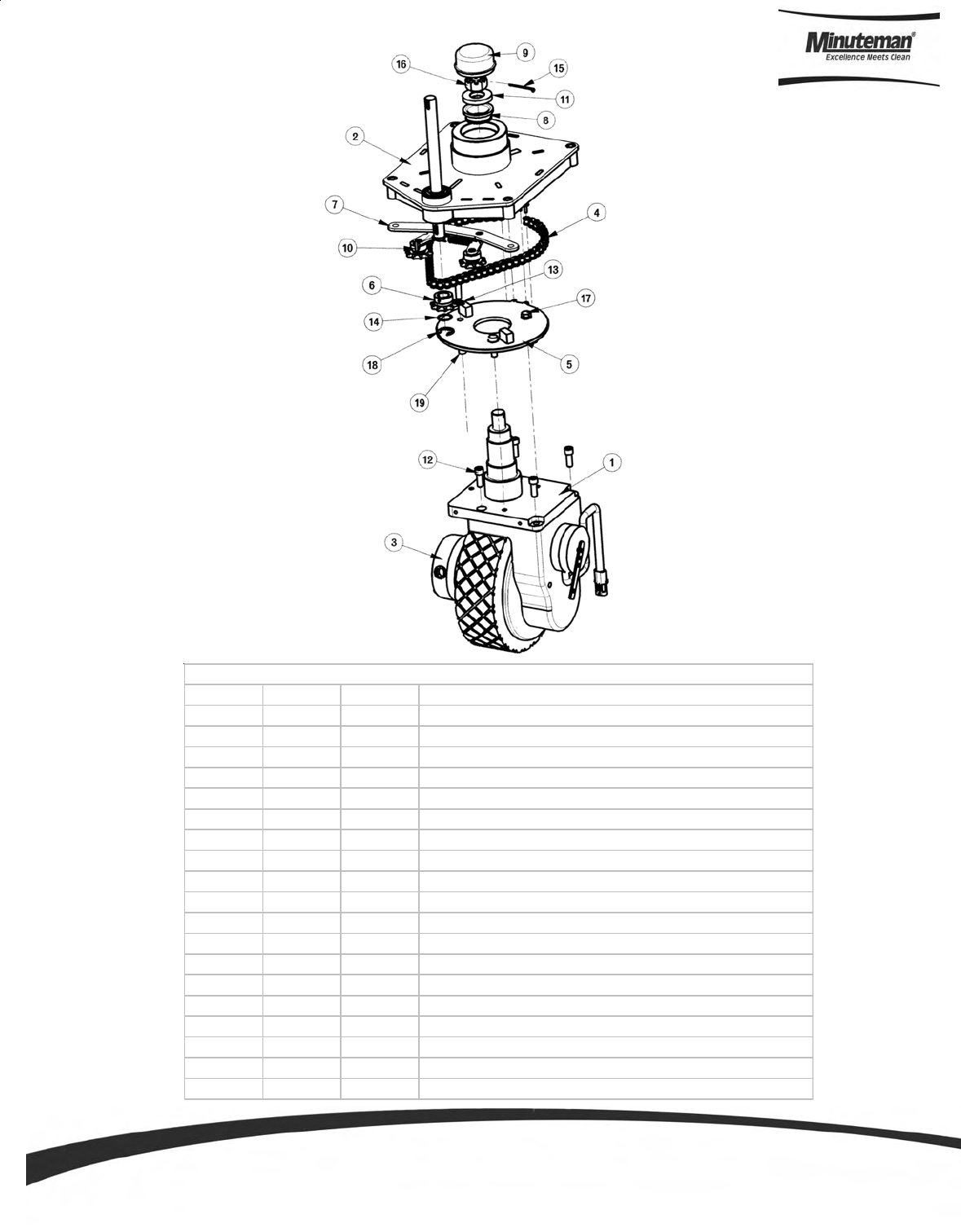
Page 34
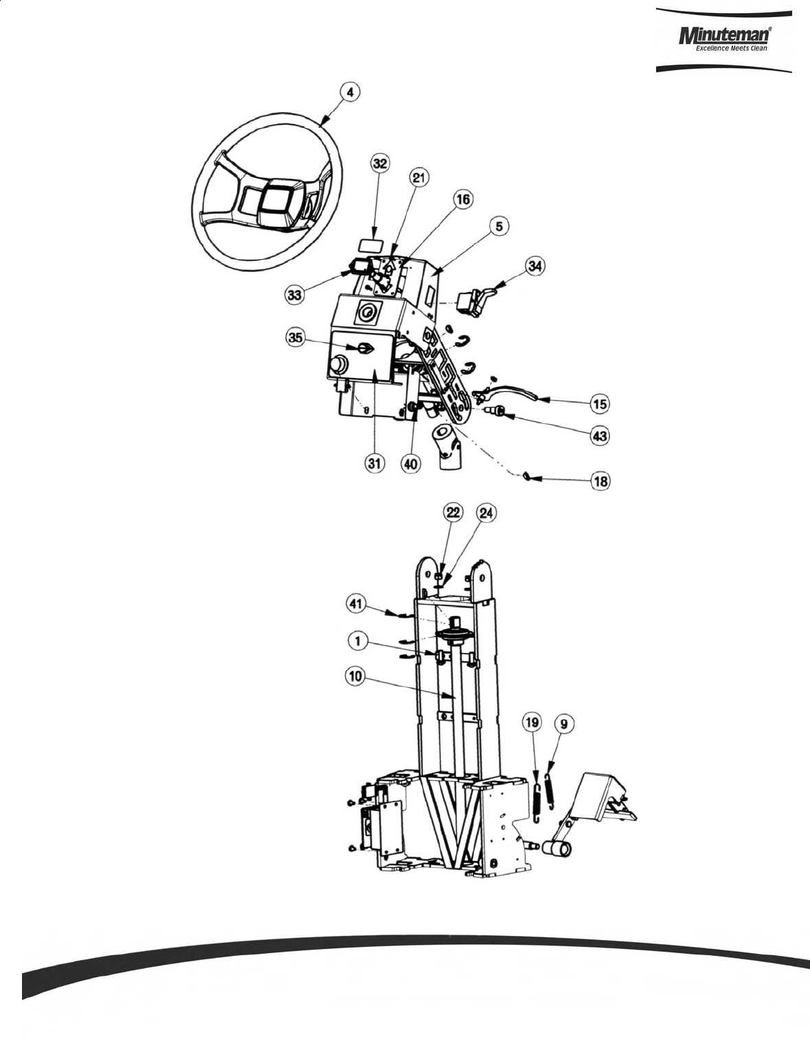
Steering Assembly I
Parts and Instruction Manual
Page 35
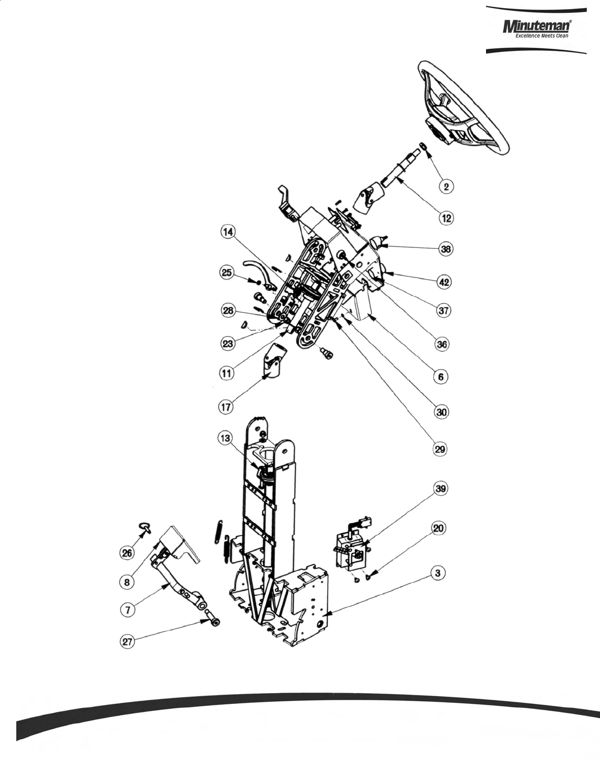
Steering Assembly II

Parts and Instruction Manual
Page 36
ITEM PART NO. REQ'D DESCRIPTION
1 70-516-16 4 BLT-CAR 5/16-18 X 1.00
2 368-816 1 HALF NUT NYLOC 1/2-20
3 241302 1 STEERING WELDMENT, LOWER
4 241311 1 STEERING WHEEL ASSEMBLY, SCV 24/26
5 241320 1 UPPER FIXED BRKT WELDMENT ASSEMBLY, SCV 24/26
6 241327 1 CTRL COVER PLATE ASSY, SCV 24/26
7 241331 1 ACCEL PEDAL WELDMENT, SCV 24/26
8 241336 1 PEDAL GUIDE WELDMENT, SCV 24/26
9 281047 1 SPRING, EXTENSION - 2.75"
10 281328 1 SHAFT,LOWER STEERING
11 281329 1 SHAFT,MIDDLE STEERING
12 281330 1 SHAFT,UPPER STEERING
13 281392 2 BEARING FLANGE ASSEMBLY 3/4 (MCH)
14 282303 1 SPRING - EXTENSION 1.375" F.L.
15 282309 1 ADJUSTMENT LEVER AND PIVOT PIN ASSY
16 320971 1 DIRECTIONAL INDICATOR ASSY
17 383098 2 UNIVERSAL JOINT
18 383277 5 KEY WOODRUFF 3/16 X 3/4
19 430051 1 RETURN SPRING-3.00"
20 710153 4 SCR-MC 10-32X.63 TH ZINC
21 710204 6 SCR-MC 6-32 X .50 ST PL PAN HD
22 711374 4 NUT-NYLOC 5/16-18
23 711380 2 NUT-NYLOC 3/8-16 NUT
24 711506 4 WSR-FLT .344 X .690 X .062 STL ZINC
25 711521 2 WSR-WAVE .21 X .44 X .02
26 711682 1 PIN-QUICK RELEASE, 1/4" DIA., .500 UL
27 712102 1 BLT- SHLDR 1/2 X 1-1/2
28 712301 2 WSR-FLAT .87 X .38 X .06
29 712540 2 SCR-MC TR HD 10-24 X .37 SS
30 712757 2 WSR - HELICAL #10 SS
31 715435 1 DECAL, MODE SELECTOR SCV 24/26
32 715505 1 DECAL, SOLUTION TANK INDICATOR
33 747011 1 BATTERY GAUGE, TRUCHARGE
34 747015 1 SWITCH, SPDT DIRECTION ES28322
35 747020 1 KNOB-MODE SELECTOR
36 747024 1 KEYSWITCH, SPST ES2832 SOLDER
37 747025 1 POTENTIOMETER ASSY WATER FLOW
38 747027 1 SWITCH ASSY, MODE SELECTOR
39 748013-1 1 POTENTIOMETER BOX ASSEMBLY
40 748047 1 HORN SWITCH, SCV 36V
41 809148 6 RETAINING RING - "E" TYPE EXT .75
42 809874 1 KNOB, SPEED CONTROL
43 712099PLT 2 BLT- SHLDR 1/2 X 5/8
BILL OF MATERIAL - 241301
Steering Assembly BOM (See Steering Assembly I & II)
Parts and Instruction Manual
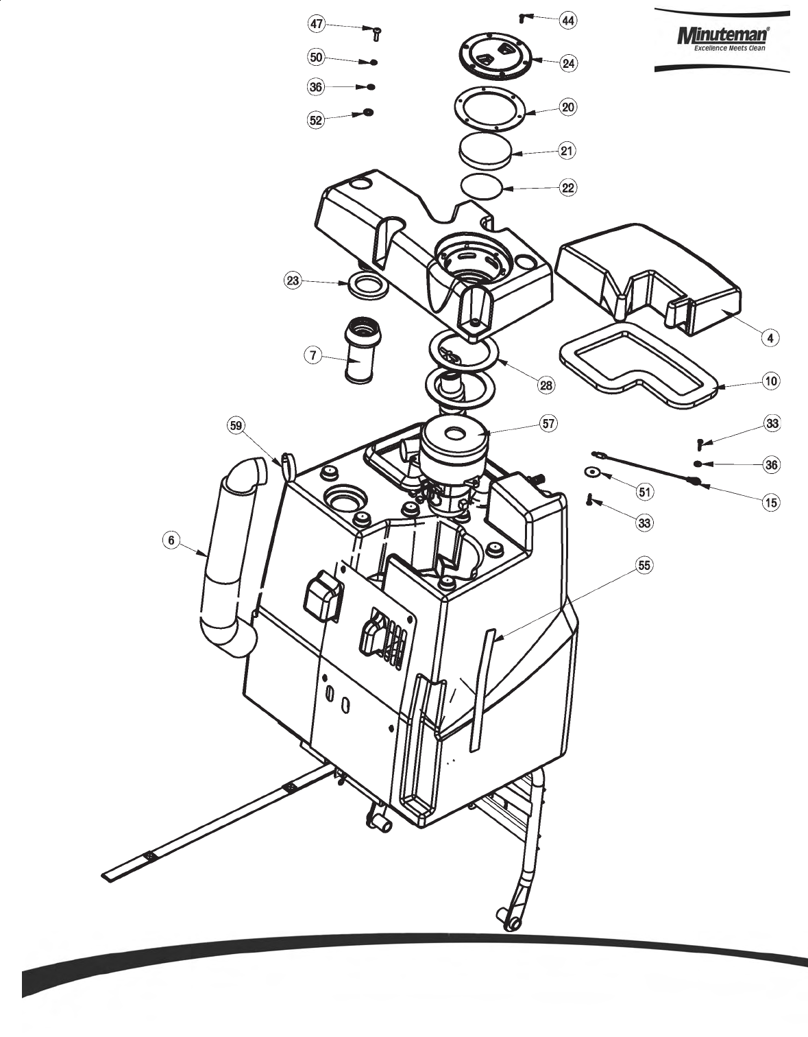
Page 37
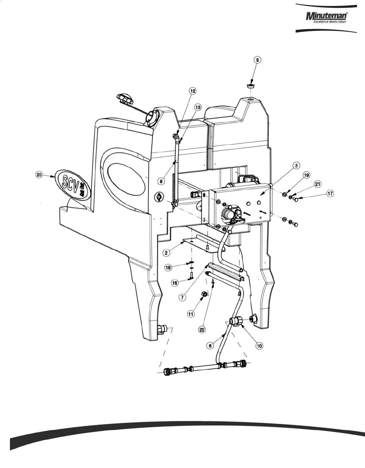
Solution Tank Assembly I
Parts and Instruction Manual
Page 38
Solution Tank Assembly II

Parts and Instruction Manual
Page 39
Solution Tank Assembly BOM (See Sol. Tank Assy. I & II)
ITEM PART NO. REQ'D DESCRIPTION
1 241002 1 SOLUTION TANK, SCV24/26
2 241041 1 SCV 24, WIRE BUNDLE, COVER PLATE
3 241098 1 PUMP SUB-ASSEMBLY w/OAW, SCV 24/26
4 241146 1 UNVENTED PLASTIC CAP w/LANYARD, SCV 24/26
5 241401 1 MAIN ELECT BOX ASSY, SCV 24/26
6 241722 1 SOLUTION TANK HOSE ASSY, SCV 24/26
7 260149 1 U CHANNEL 12"
8 260340 1 SOLUTION TANK SIGHT LEVEL TUBE, SCV 24/26
9 281371 1 VENT PLUG
10 281427 2 #35 SHUTOFF, BLACK, ZERO PRS
11 430114 1 1/4" FPT PLASTIC CAP
12 450040 2 FITTING 90 3/8 MPT X 3/8 BARB
13 450092 2 CRIMP CLAMP 27/64" TO 17/32"
14 710180 4 SCR-MC 1/4-20 X .75 ZINC
15 711161 4 SCR-HI/LO 10 X 3/4 STL BLK ZINC
16 711206 2 BLT-HH 1/4-20 X .87 ST PL
17 711229 4 BLT-HH 5/16-18 x .875
18 711505 6 WSR-FLAT 1/4
19 711506 4 WSR-FLT .344 X .690 X .062 STL ZINC
20 711544 6 WSR-HELICAL 1/4
21 711545 4 WSR-HELICAL 5/16
22 712822 2 SCR-MC TR HD 10-24 X .50 SS
23 715363 2 DECAL, SCV 24/26
24 742708-4 1 FLOAT SWITCH W/WEATHER PACK
25 713508MCH 1 SPINWELD # 20D MACHINED
BILL OF MATERIAL - 241012
Parts and Instruction Manual
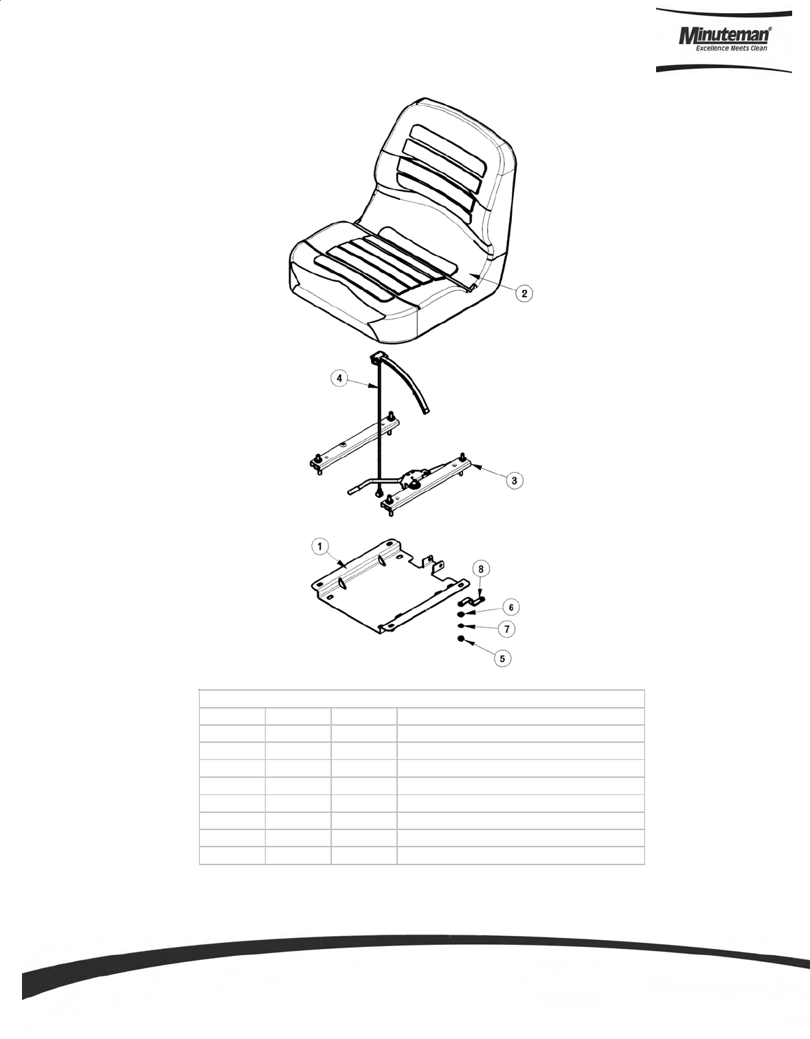
Page 40
ITEM PART NO. REQ'D DESCRIPTION
1 241376 1 SEAT BRACKET WMT, SCV 24/26
2 281085 1 ASS'Y SEAT, SUPER SUBURBAN
3 281086 1 SLIDE ASS'Y KIT
4 281087-2 1 SEAT SWITCH ASSEMBLY, SCV 24/26
5 711319 4 5/16-18 HEX NUT
6 711506 4 WSR-FLT .344 X .690 X .062 STL ZINC
7 711545 4 WSR-HELICAL 5/16
8 748255 1 SEAT GROUND STRAP, SCV 24/26
BILL OF MATERIAL - 241365
Seat Assembly
Parts and Instruction Manual
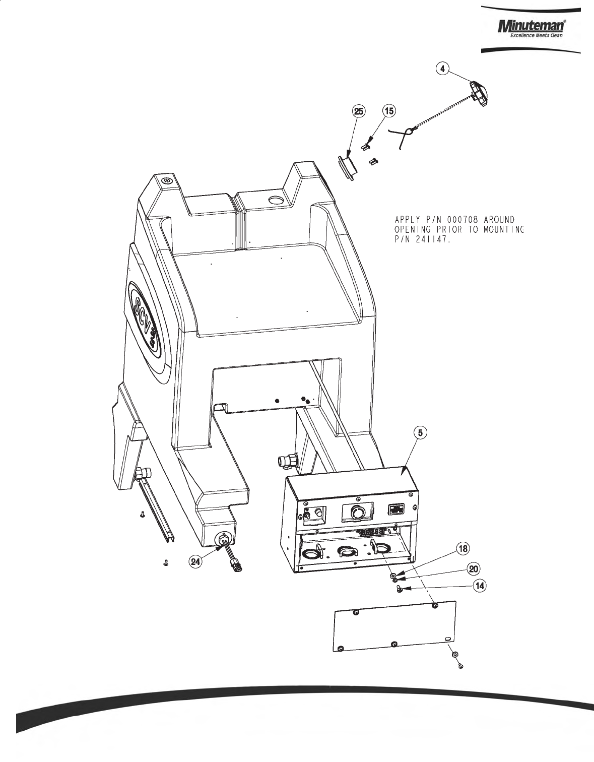
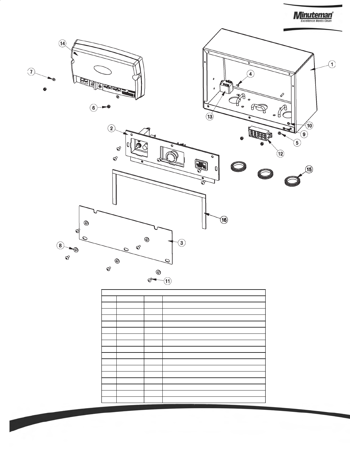
Page 41
Electrical Panel Assembly
ITEM PART NO. REQ'D DESCRIPTION
1 241402 1 ELECTRICAL BOX WDMNT, SCV 24/26
2 241404 1 E-STOP PANEL ASSEMBLY, SCV 24/26
3 241409 1 ELECTRICAL PANEL DOOR, SCV 24/26
4 710202 2 SCR-MC 6-32 X .25 ST PL PAN HD
5 711304 1 NUT-HEX 8-32 ST PL
6 711372 4 NUT-NYLOC 8-32 STL ZINC
7 711502 2 WSR-FLT .170 x.38 x.032 STL ZINC
8 711505 5 WSR-FLAT 1/4
9 711542 1 WSR-HELICAL #8
10 711552 1 WSR - INTERNAL LOCK #8
11 712822 10 SCR-MC TR HD 10-24 X .50 SS
12 744005 1 TERMINAL BLOCK EAGLE 3
13 748204 1 RELAY, 36VDC DPDT
14 748206 1 CONTROLLER,TRIO PLUS SCV2426
15 281449 1.125 SERRATED GROMMET STRIP
16 830557 2.1 DORTITE 1/2" RM IF
BILL OF MATERIAL - 241401
Parts and Instruction Manual
Page 42
Recovery Tank Assembly I
Parts and Instruction Manual
Page 43
Recovery Tank Assembly II

Parts and Instruction Manual
Page 44
Recovery Tank BOM (See Recovery Tank Assembly I & II)
ITEM PART NO. REQ'D DESCRIPTION ITEM PART NO. REQ'D DESCRIPTION
1 200289 1 DUMP HOSE ASM 31 710180 2 SCR-MC TR HD 1/4-20x.75 STL ZINC
2 241003 1 RECOVERY TANK, SCV 24/26 32 710530 2 SCR-MC FL HD 8-32 X .50 BRS
3 241006 1 FIXED LID, SCV 24/26 33 711107 2 SCR-ST-A #10 X 1.00 PL
4 241007 1 LID, RECOVERY TANK REMOVABLE 34 711228 6 BLT-HH 5/16-18 X .75 ST PL
5 241037 1 RECOVERY TANK FRAME WELDMENT, SCV 24/26 35 711420 4 NUT- HEX JAM 5/16-18 ST PL
6 241049 1 VAC MOTOR MUFFLER, SCV 24/26 36 711504 7 WSR-FLAT 1/4 ID SS
7 241060 1 SCREENED FLOAT 37 711505 2 WSR-FLAT 1/4
8 241076 1 VAC WIRE COVER, SCV 24/26 38 711515 1 WSR-FLAT .406 X .812 X .0625
9 241099 1 EXHAUST/VAC WIRE COVER, SCV 24/26 39 711544 2 WSR-HELICAL 1/4
10 241193 1 REMOVABLE LID GASKET, SCV 24/26 40 711545 6 WSR-HELICAL 5/16
11 241420 1 EXHAUST DIVERTER, SCV 24/26 41 711575 6 WSR-FLT .31x.75x..06ST
12 241433 1 RECOVERY TANK SAFETY STRAP, SCV 24/26 42 711678 1 CLEVIS PIN 3/8 X 2-1/4
13 241435 1 REC. TANK OAW SOLUTION FEED HOSE, SCV 24/26 43 711808 2 COTTER PIN-HAIR #13
14 241519 2 ACTUATOR PROTECT BKT 44 712516 6 SCR-BHCS #8-32 x .62 SS
15 241704 1 REMOVABLE COVER LANYARD ASSY, SCV 24/26 45 712536 2 SCR-MC 10-24 X .62 TH SS
16 241803 1 INLET WELDMENT GASKET, SCV 24/26 46 712537 4 10-24 X .75 SS TRUSS HD SCR
17 241805 1 REC TANK VAC INLET PIPE WELDMENT (OAW), SCV 24/26 47 712541 6 SCR-MC 1/4-20 X 1.00 TH SS
18 260203 1 WIRE GRIP HOSE CLAMP 48 712638 2 NUT, HEX 10-24 SS NYLOC
19 260579 1 TOOL CLIP, 1.5" HOSE 49 712757 4 WSR - HELICAL #10 SS
20 281018 1 GASKET, NEO 6.00 X 4.50 X .125 50 712758 6 WSR-HELICAL 1/4 SS
21 281055 1 VAC MOTOR FILTER 51 712761 1 WSR-FLAT .28 X 1.25 X .059SS
22 281056 1 VAC MOTOR INLET SCREEN 52 712767 6 FLAT WASHER .406 ID X .75 OD X .
23 281073 1 INLET GASKET 53 712810 9 SCR-MC 10-24 X .37 ST PL
24 281423 1 FILL CAP W/CHAIN ASSY 4.00 54 712822 3 SCR-MC TR HD 10-24 X .50 SS
25 320835 1 ES2832 DUMP CAP COVER 55 715717 1 DECAL, OVERFILL SIGHT GAUGE, SCV 24/26
26 320838 1 STOPPER PLUG ASM - 4" 56 740821-1 1 ACTUATOR ASSEMBLY, LINAK
27 320839 1 DUMP COVER SUPPORT RING 57 742773 1 VACUUM ASSEMBLY, SCV
28 380035 2 MOTOR GASKET 58 760286 1 HOOK, WIRE FORMED
29 450221 1 Q.C. COUPLING (FEMALE) 59 760859 1 CLAMP, HOSE
30 450223 1 FITTING BRASS 1/8 FPT - 1/8 BARB 60 830082 1 HOSE CLAMP 3/8
BILL OF MATERIAL - 241013
Parts and Instruction Manual
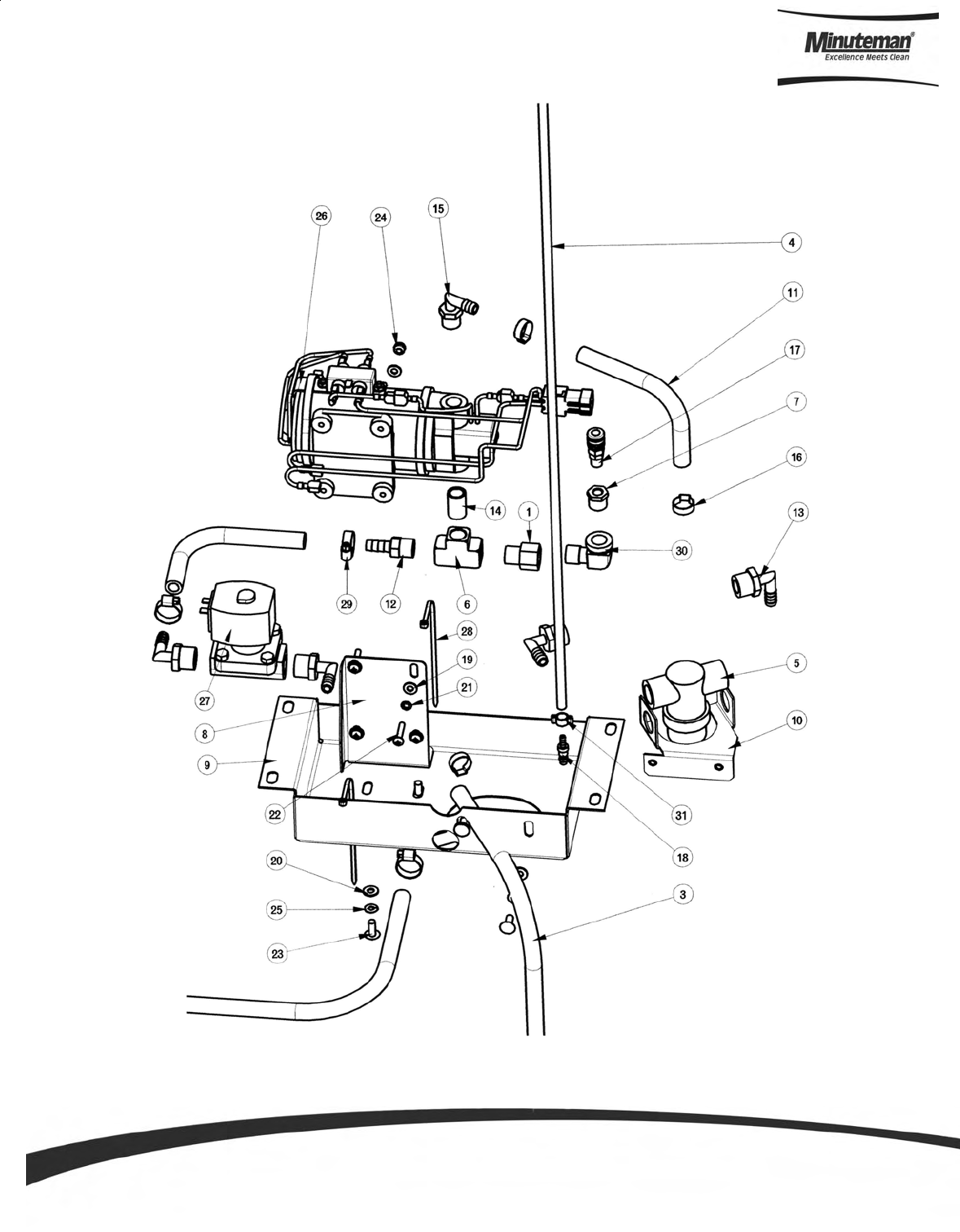
Page 45
Pump Assembly

Parts and Instruction Manual
Page 46
ITEM PART NO. REQ'D DESCRIPTION
1 210409 1 FITTING ADAPTOR 3/8MPTx38/FPT BR
2 241096 1 HOSE 3/8 x 45" WIRE REINFORCED, SCV 24/26
3 241097 1 HOSE 3/8 x 31 WIRE REINFORCED, SCV 24/26
4 241430 1 OAW SOLUTION FEED HOSE, SCV 24/26
5 281089 1 FILTER, IN-LINE
6 281090 1 FITTING BRASS 3/8" FPT TEE
7 281091 1 FITTING 3/8MPTx1/8 FPT REDUCER
8 281368 1 PUMP MOUNT PLATE
9 281369 1 PUMP SUPPORT PLATE
10 281388 1 PUMP MTG PLATE
11 320254 2 HOSE 3/8 x 9.00" WIRE REINFORCED
12 342430 1 FITTING BRASS 3/8MPT X 3/8BARB
13 383327 4 ELBOW 1/2 MPT X 3/8 BARB
14 383332 1 FITTING BRASS 3/8 NIPPLE
15 450040 1 FITTING 90 3/8 MPT X 3/8 BARB
16 450076 3 CRIMP CLAMP SS 185R
17 450221 1 Q.C. COUPLING (FEMALE)
18 450279 2 Q.C. COUPLING NIPPLE (MALE X 1/8 BARB)
19 711503 8 WSR, FLAT#10
20 711504 4 WSR-FLAT 1/4 ID SS
21 711553 4 WSR- INTERNAL LOCK #10
22 712531 4 SCR-MC 10-24 X 1.00 SS
23 712565 4 SCR-MC 1/4-20X.63 SS TR HD
24 712638 4 NUT, HEX 10-24 SS NYLOC
25 712758 4 WSR-HELICAL 1/4 SS
26 742709-2 1 PUMP ASSEMBLY-SCV
27 742718-1 1 SOLENOID VALVE 36V
28 828062 2 CABLE TIE ..05 x .14 x 8"
29 829129 3 HOSE CLAMP MICRO-SEAL
30 830062 1 FITTING 90 STREET ELBOW 3/8x3/8
31 830082 2 HOSE CLAMP 3/8
BILL OF MATERIAL - 241098
Pump Assembly BOM
Parts and Instruction Manual
Page 47
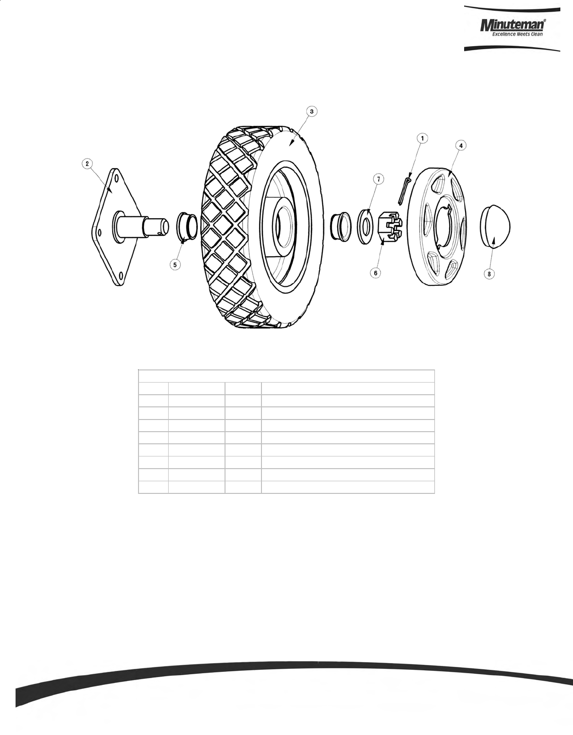
ITEM PART NO. REQ'D DESCRIPTION
1 380-632-20 1 3/16 COTTER PIN
2 241202 1 REAR AXLE WELDMENT, SCV 24/26
3 241210 1 REAR WHEEL ASSY
4 241212 1 REAR WHEEL HUB CAP, SCV 24/26
5 383194 2 BEARING CONE
6 711450 1 NUT-SLOTTED, 1-14 UNS
7 711514 1 WSR-FT 1.0 ID X 2.0 OD
8 383241PTD 1 GREASE CAP WHEEL-PAINTED
BILL OF MATERIAL - 241201
Rear Axle Assembly
Parts and Instruction Manual
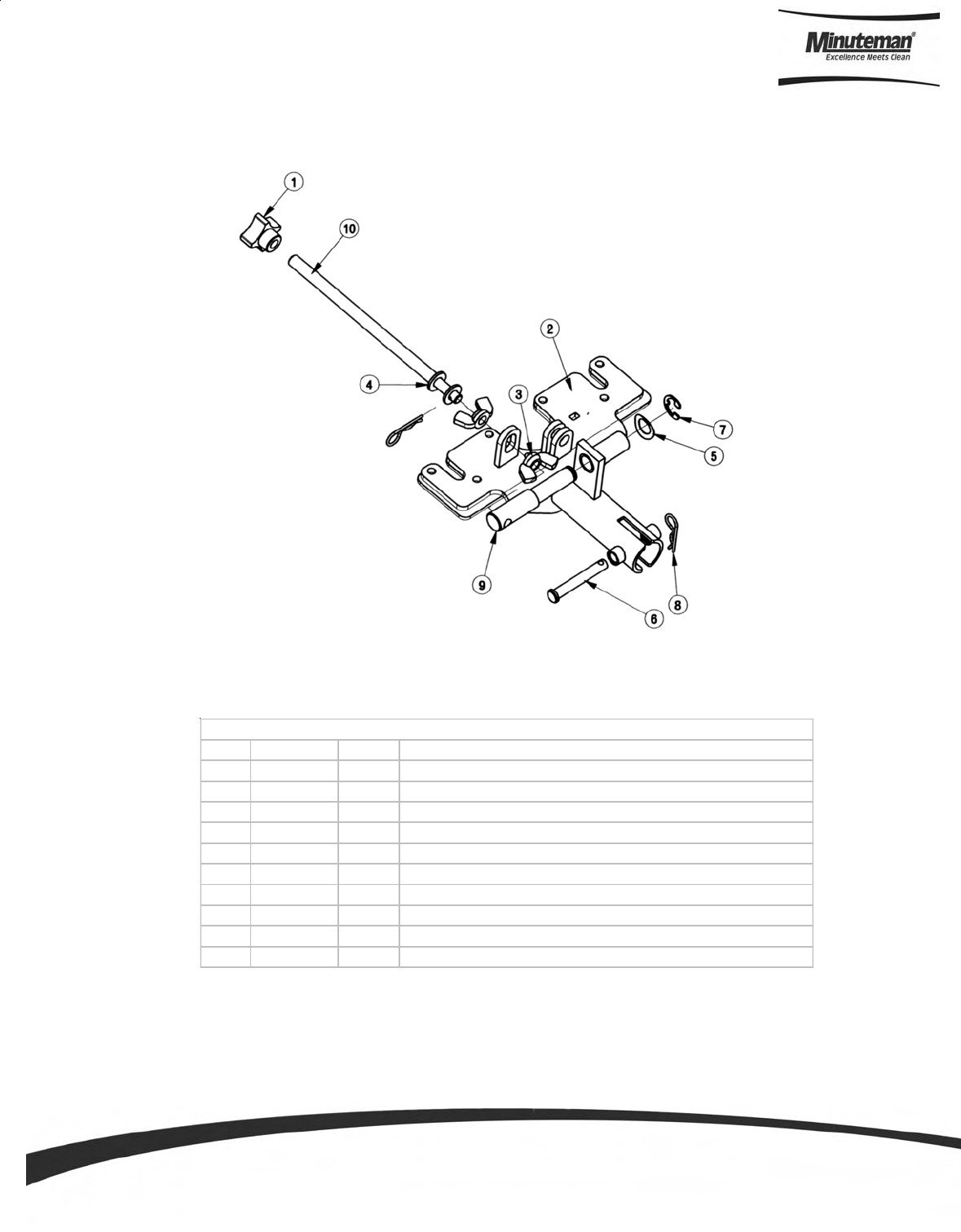
Page 48
ITEM PART NO. REQ'D DESCRIPTION
1 241004 1 KNOB,3/8-16 FOUR PRONG.
2 241751 1 REAR SQUEEGEE MOUNT PLATE W MT, SCV 24/26
3 711367 2 NUT-W ING 3/8-16 ST PL
4 711506 2 W SR-FLT .344 X .690 X .062 STL ZINC
5 711524 1 W SR-W AVE .52 X .87 X .01
6 711671 1 CLEVIS PIN .31X2.13 11-10
7 711713 1 RETAINING RING -"E" TYPE EXT .500
8 711808 2 COTTER PIN-HAIR #13
9 762005 1 ADJUSTING PIN, THREADED
10 762006 1 THREADED ROD, 3/8-16 X 7.5" LG
BILL OF MATERIAL -241730
Squeegee Mechanism Assembly
Parts and Instruction Manual
Page 49
ITEM PART NO. REQ'D DESCRIPTION
1 241721 1 SQUEEGEE WMT ASS'Y, SCV 24/26
2 241745 2 WING BOLT 3/8-16 X 1.00
3 281074 1 SQUEEGEE TOGGLE CLAMP, 2800
4 281075 1 SQUEEGEE LATCH, 2800
5 281732 1 STRAP - FRONT CLAMP
6 281734 1 STRAP - FRONT STOP
7 281736 1 STRAP - REAR CATCH
8 281738 1 STRAP - REAR LATCH
9 281740 1 STOP BAR
10 281763 1 PB FRONT BLADE,SQUEE GUM RUBBER
11 281764 1 PB REAR BLADE, SQUEEGEE GUM RUBBER
12 430325 2 CASTER 3/8"-16 X 1.50"
13 710530 7 SCR-MC FL HD 8-32 X .50 BRS
14 711026 5 NUT, HEX 8-32 NYLOC SS
15 711367 2 NUT- WING 3/8-16 ST PL
16 711507 6 WSR-FLAT .37 X 1.12 X .06
17 711515 2 WSR-FLAT .406 X .812 X .0625
18 711546 2 WSR-HELICAL 3/8
19 711550 4 WSR NYLON .25 ID X .75 OD
20 711560 2 SCREW-HH 1/4-20X1.00 NYLON
21 711563 2 NUT- WING 1/4-20 NYLON
22 712091 2 SHOULDER BLT 3/8 X 1.50
23 808829 2 WHEEL,TRUCK
24 832015 2 SPACER .38 X .50 X .140
BILL OF MATERIAL - 241740
Rear Squeegee Assembly
Parts and Instruction Manual
Page 50
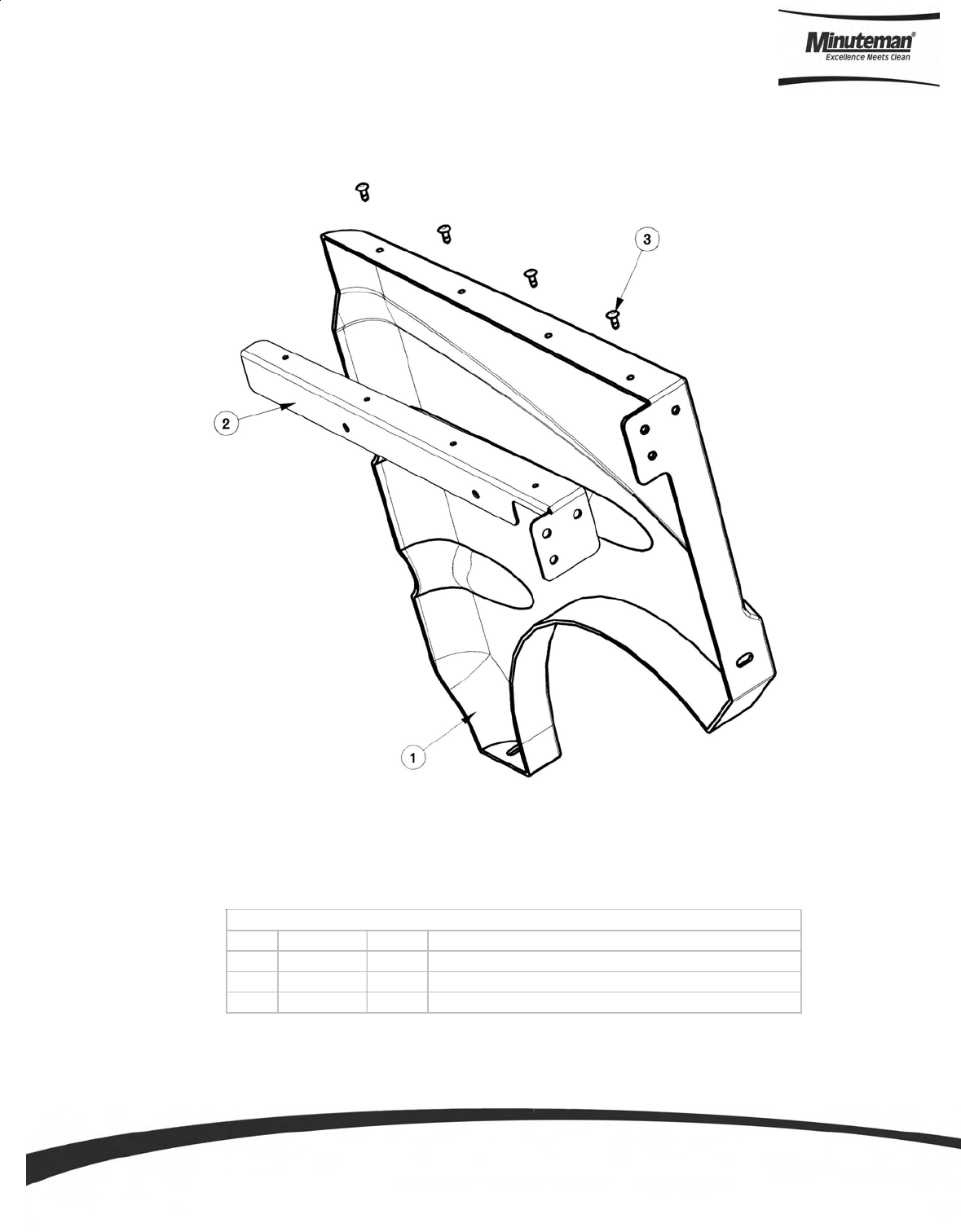
ITEM PART NO. REQ'D DESCRIPTION
1 241021 1 LH BATTERY PANEL, SCV 24/26
2 241043 1 LEFT SIDE PANEL SUPPORT BRKT, SCV 24/26
3 711923 4 POP RIVET 3/16 "
BILL OF MATERIAL -241045
Battery Panel Assembly (Left Hand Side)
Parts and Instruction Manual
Page 51
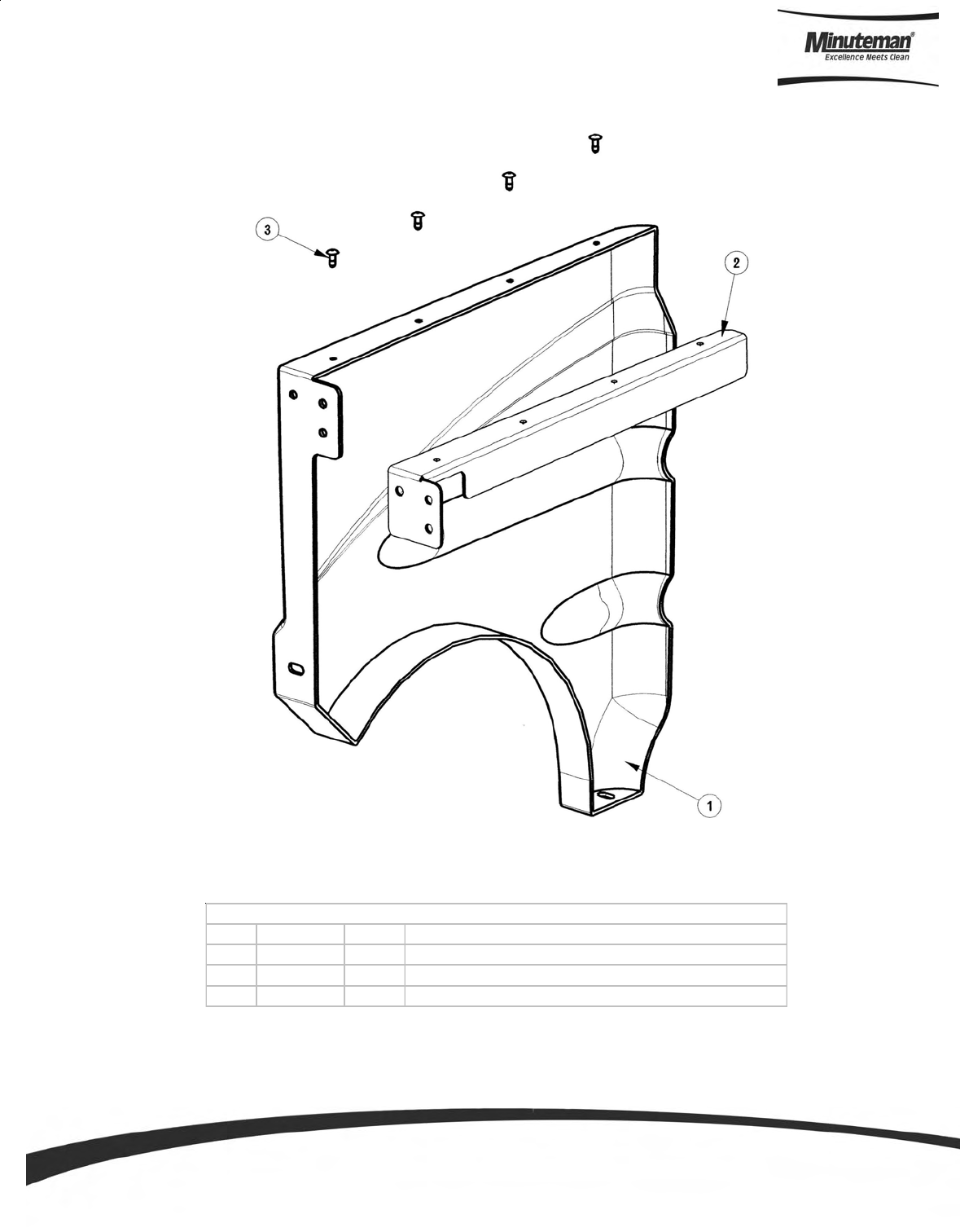
ITEM PART NO. REQ'D DESCRIPTION
1 241022 1 RH BATTERY PANEL, SCV 24/26
2 241044 1 RIGHT SIDE PANEL SUPPORT BRKT, SCV 24/26
3 711923 4 POP RIVET 3/16"
BILL OF MATERIAL -241046
Battery Panel Assembly (Right Hand Side)
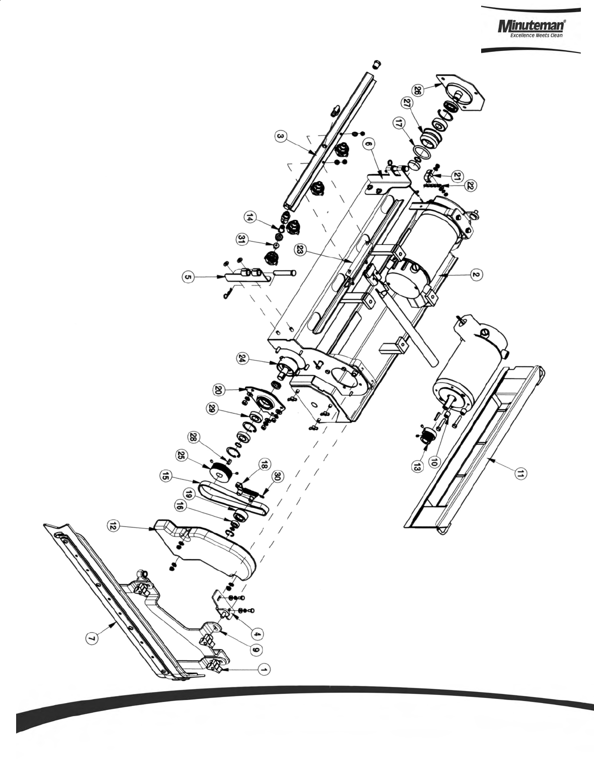
Parts and Instruction Manual
Page 52
24” Cylindrical Scrub Deck Assembly I (Items 1-
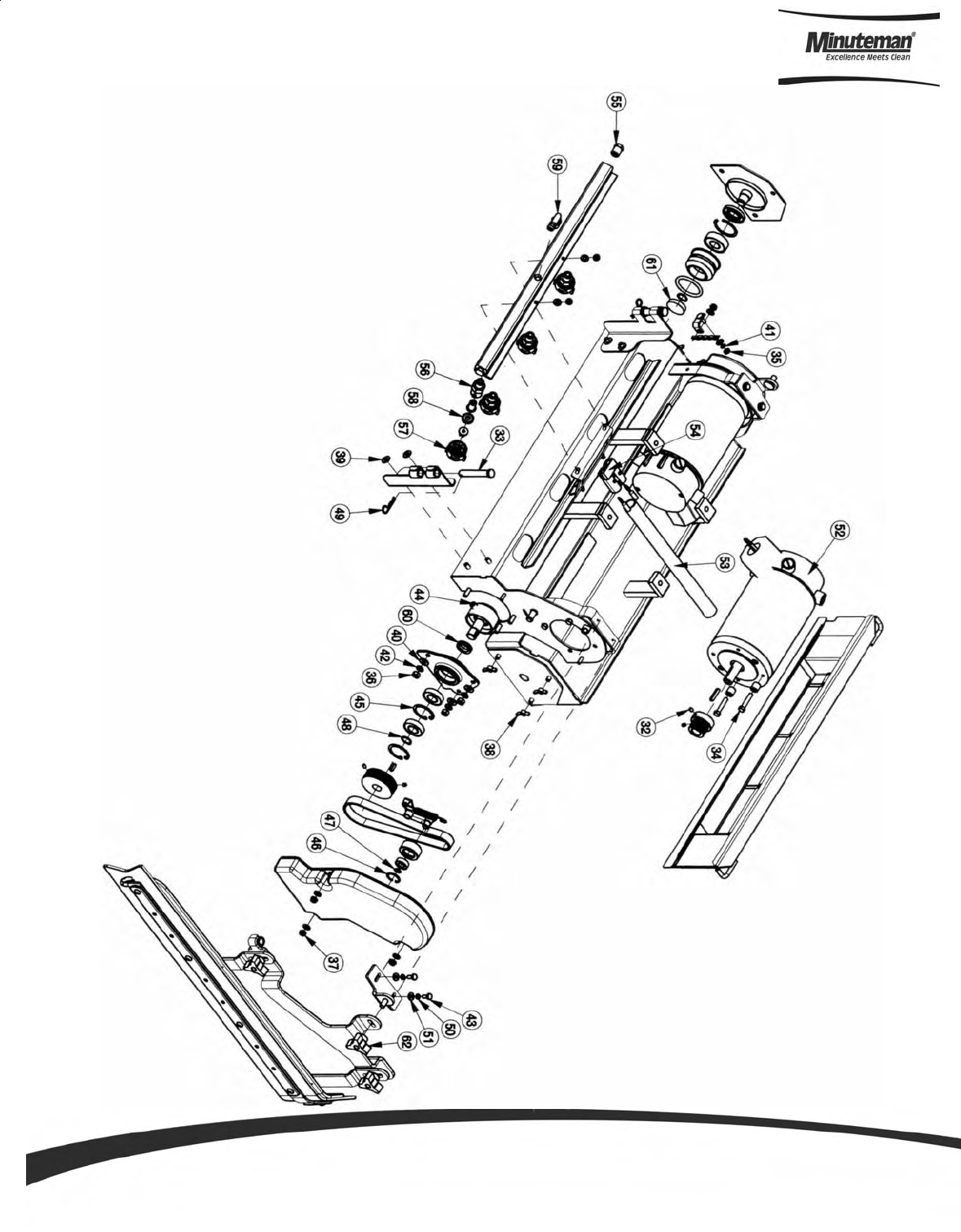
Parts and Instruction Manual
Page 53
24” Cylindrical Scrub Deck (Items 32-62)

Parts and Instruction Manual
Page 54
ITEM PART NO. REQ'D DESCRIPTION ITEM PART NO. REQ'D DESCRIPTION
1 210118 4 KNOB-3 SIDED 5/16 NYLOC 32 711003 8 SCR-SK 10-32 x .25
2 241502 1 CYLINDRICAL SCRUBDECK WELDMENT, SCV 24 33 711119 2 CLEVIS PIN 7/16 X 2-5/8
3 241512 1 SPRAY BAR, CYL SCRUBDECK, SCV 24/26 34 711210 8 BLT-HH 1/4-20 X 1.25 STPL
4 241542 2 UPPER SQUEEGEE MTG BRK'T 35 711310 1 NUT, HEX 10-32 ST PL
5 241544 1 HINGE BRKT WLDMNT RH, SCV2426 36 711316 6 NUT-HEX 1/4-20 ST PL
6 241546 1 HINGE BRKT WLDMNT LH,SCV2426 37 711350 10 NUT NYLOC 10-32
7 241552 1 LOWER SIDE SQUEEGEE ASSY LH, SCV 24/26 38 711389 6 NUT-WING 1/4-20 STL ZINC
8 241553 1 LOWER SIDE SQUEEGEE ASSY RH, SCV 24216 39 711504 4 WSR-FLAT 1/4 ID SS
9 241554 1 UPPER SQUEE BRK'T WMT LH, SCV 24/26 40 711505 6 WSR-FLAT 1/4
10 241598 8 MOTOR SPACER CYL DECK, SCV 24/26 41 711543 1 WSR - HELICAL #10
11 241901 1 DEBRIS BOX WMT, CYL SCRUBDECK 24" 42 711544 6 WSR-HELICAL 1/4
12 281023 2 BELT COVER, CYLINDRICAL SCRUBDECK 43 711623 4 SCR-MC IND. HH 10-24 X .50 STPL
13 281036 2 OFFSET PULLEY POLY V 44 711676 4 ROLL PIN, 3/8 x 3/4
14 281041 4 CHECK VALVE 45 711701 2 RETAINING RING, INT 1.37
15 281053 2 J BELT ( POLY V ) 18" 46 711704 2 INTERNAL RETAINING RING N5000-86 .875 DIA.
16 281058 2 BEARING 3/8" RADIAL 47 711724 4 3/8" RETAINING RING, EXTERNAL
17 281519 2 O-RING 1.62 X 2.00 X .188 48 711725 4 5/8" RETAINING RING, EXTERNAL
18 281544 2 TENSIONER ARM WELDMT 49 711808 2 COTTER PIN-HAIR #13
19 281548 2 BELT IDLER 50 712757 4 WSR - HELICAL #10 SS
20 281550 2 BEARING HOUSING, CYL SCRUBDECK 51 712764 4 WSR #10 SS
21 281557 1 DRAG CHAIN BRK'T, CYL. SCRUBDECK 52 748102 2 MOTOR 3/4 HP, 36V, 1800RPM
22 281558 1 DRAG CHAIN, CYL. SCRUBDECK 53 748141 1 CABLE WRAP, 11"
23 281606 1 SPRAY HEAD MTG BRKT 54 748215 1 CIRCUIT BRKR - SB50 GRAY HOUSING ONLY
24 281675 2 DRIVE HUB, CYL SCRUBDECK 55 829619 2 END PLUG
25 281676 2 DRIVEN PULLEY,CYL SCRUBDECK 56 833140 4 BODY INLET CONNECTOR
26 281681 2 IDLE SHAFT WMT, CYL DECK 57 833141 4 CAP
27 281683 2 IDLE HUB ASSY 58 833142 4 GASKET CAP
28 361252 2 KEY, WOODRUFF, 3/16 SQ X .5 59 833325 1 FITTING NYLON 90 1/4MPT X 3/8HB
29 383558 4 BEARING, RADIAL 5/8" R10 60 833605 2 VRING SEAL
30 430051 2 RETURN SPRING-3.00" 61 833611 2 END CAP
31 450122 2 UNIJET SPRAY TIP 6503 62 210118Y 2 KNOB 5/16" THREAD, YELLOW
BILL OF MATERIAL - 241702
24”Cylindrical Scrub Deck BOM (See Assembly I & II)
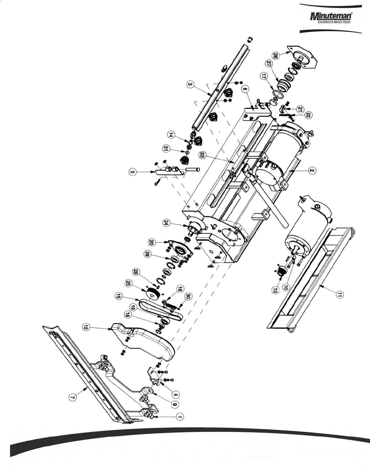
Parts and Instruction Manual
Page 55
26” Scrub Deck Assembly I (Items 1-31)
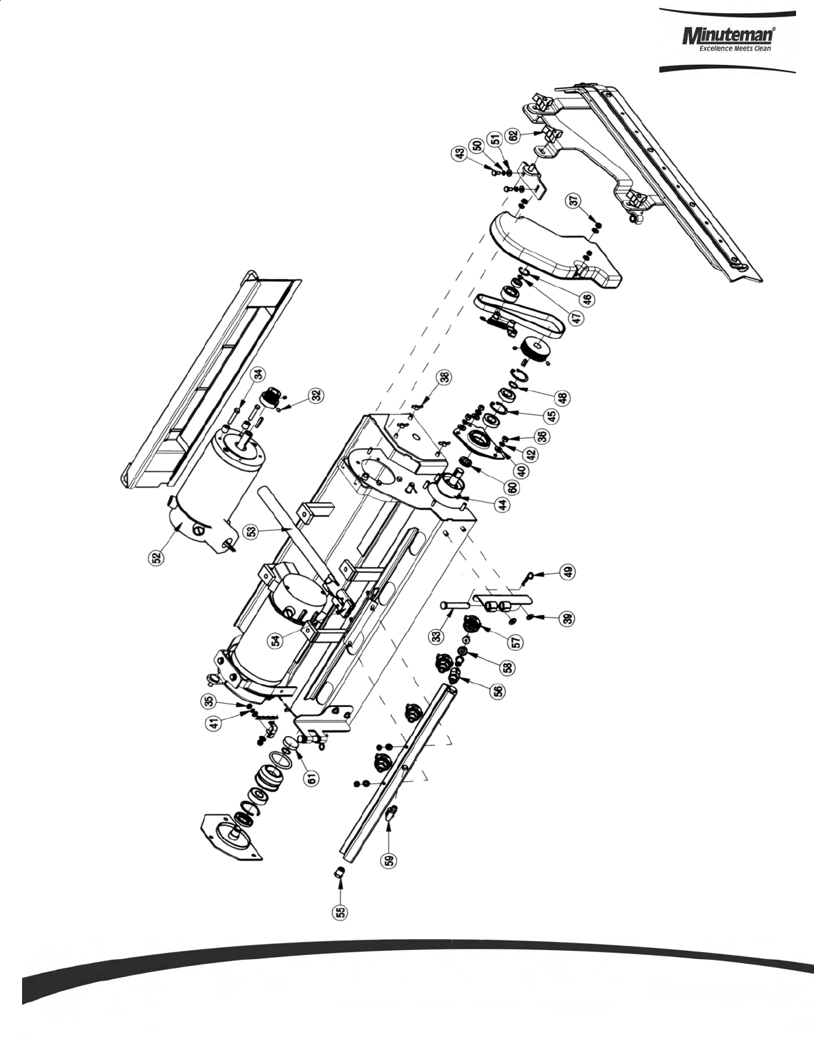
Parts and Instruction Manual
Page 56
26” Cylindrical Scrub Deck Assembly II (Items 32-62)

Parts and Instruction Manual
Page 57
ITEM PART NO. REQ'D DESCRIPTION ITEM PART NO. REQ'D DESCRIPTION
1 210118 4 KNOB-3 SIDED 5/16 NYLOC 32 711003 8 SCR-SK 10-32 x .25
2 241503 1 CYLINDRICAL SCRUBDECK WELDMENT, SCV 26 33 711119 2 CLEVIS PIN 7/16 X 2-5/8
3 241512 1 SPRAY BAR, CYL SCRUBDECK, SCV 24/26 34 711210 8 BLT-HH 1/4-20 X 1.25 STPL
4 241542 2 UPPER SQUEEGEE MTG BRK'T 35 711310 1 NUT, HEX 10-32 ST PL
5 241544 1 HINGE BRKT WLDMNT RH, SCV2426 36 711316 6 NUT-HEX 1/4-20 ST PL
6 241546 1 HINGE BRKT WLDMNT LH,SCV2426 37 711350 10 NUT NYLOC 10-32
7 241552 1 LOWER SIDE SQUEEGEE ASSY LH, SCV 24/26 38 711389 6 NUT-WING 1/4-20 STL ZINC
8 241553 1 LOWER SIDE SQUEEGEE ASSY RH, SCV 24216 39 711504 4 WSR-FLAT 1/4 ID SS
9 241554 1 UPPER SQUEE BRK'T WMT LH, SCV 24/26 40 711505 6 WSR-FLAT 1/4
10 241598 8 MOTOR SPACER CYL DECK, SCV 24/26 41 711543 1 WSR - HELICAL #10
11 241961 1 DEBRIS BOX WMT, CYL SCRUBDECK 26" 42 711544 6 WSR-HELICAL 1/4
12 281023 2 BELT COVER, CYLINDRICAL SCRUBDECK 43 711623 4 SCR-MC IND. HH 10-24 X .50 STPL
13 281036 2 OFFSET PULLEY POLY V 44 711676 4 ROLL PIN, 3/8 x 3/4
14 281041 4 CHECK VALVE 45 711701 2 RETAINING RING, INT 1.37
15 281053 2 J BELT ( POLY V ) 18" 46 711704 2 INTERNAL RETAINING RING N5000-86 .875 DIA.
16 281058 2 BEARING 3/8" RADIAL 47 711724 4 3/8" RETAINING RING, EXTERNAL
17 281519 2 O-RING 1.62 X 2.00 X .188 48 711725 4 5/8" RETAINING RING, EXTERNAL
18 281544 2 TENSIONER ARM WELDMT 49 711808 2 COTTER PIN-HAIR #13
19 281548 2 BELT IDLER 50 712757 4 WSR - HELICAL #10 SS
20 281550 2 BEARING HOUSING, CYL SCRUB DECK 51 712764 4 WSR #10 SS
21 281557 1 DRAG CHAIN BRK'T, CYL. SCRUBDECK 52 748102 2 MOTOR 3/4 HP, 36V, 1800RPM
22 281558 1 DRAG CHAIN, CYL. SCRUBDECK 53 748141 1 CABLE WRAP, 11"
23 281606 1 SPRAY HEAD MTG BRKT 54 748215 1 CIRCUIT BRKR - SB50 GRAY HOUSING ONLY
24 281675 2 DRIVE HUB, CYLINDRICAL SCRUBDECK 55 829619 2 END PLUG
25 281676 2 DRIVEN PULLEY 56 833140 4 BODY INLET CONNECTOR
26 281681 2 IDLE SHAFT WMT 57 833141 4 CAP
27 281683 2 IDLE HUB ASSY 58 833142 4 GASKET CAP
28 361252 2 KEY, WOODRUFF, 3/16 SQ X .5 59 833325 1 FITTING NYLON 90 1/4MPT X 3/8HB
29 383558 2 BALL BEARING, RADIAL 5/8" R10 60 833605 2 VRING SEAL
30 430051 2 RETURN SPRING-3.00" 61 833611 2 END CAP
31 450122 2 UNIJET SPRAY TIP 6503 62 210118Y 2 KNOB-3 SIDED 5/16 NYLOC
BILL OF MATERIAL - 241703
26” Cylindrical Scrub Deck BOM (See Assembly I & II)
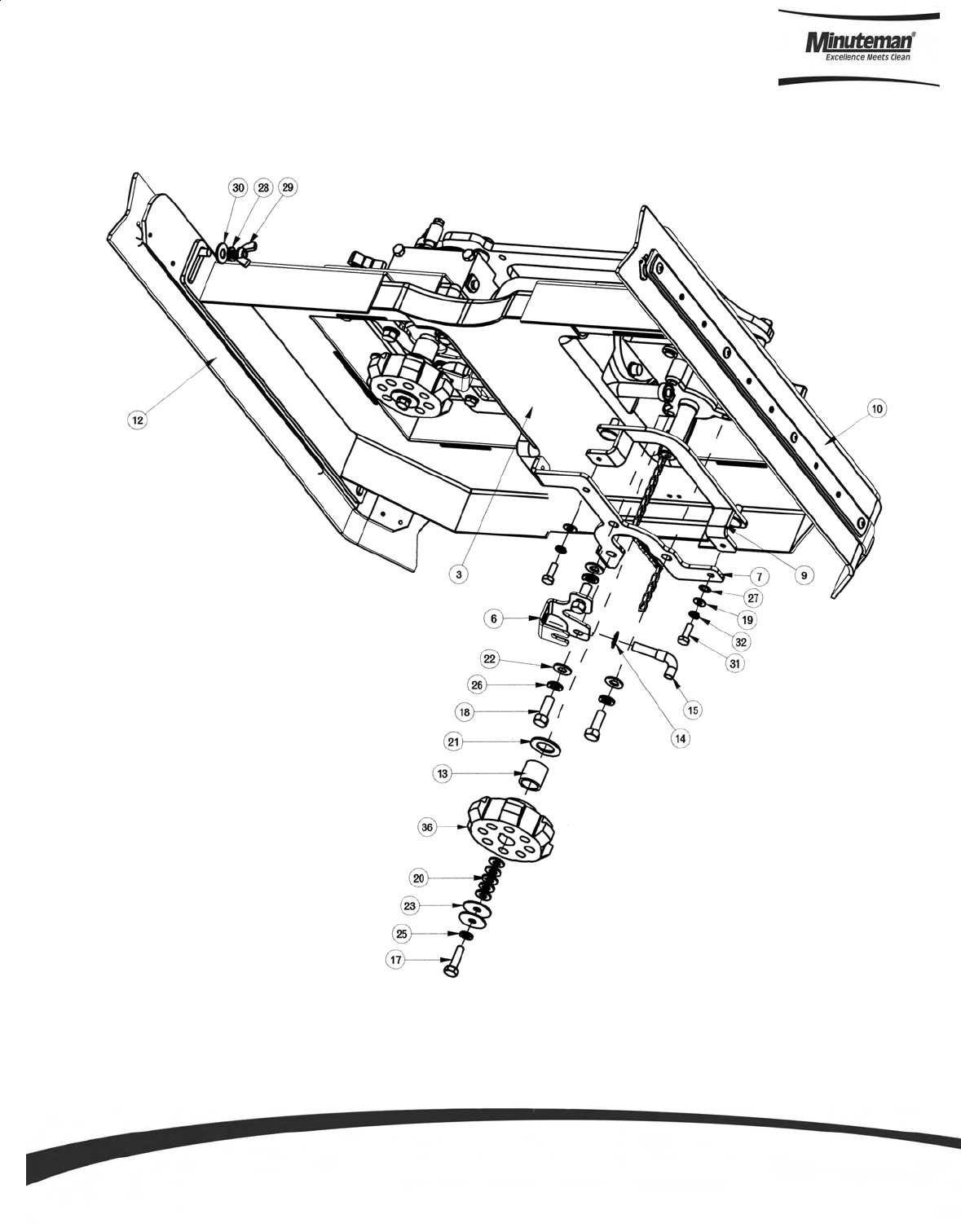
Parts and Instruction Manual
Page 58
24” Disc Scrub Deck Assembly I
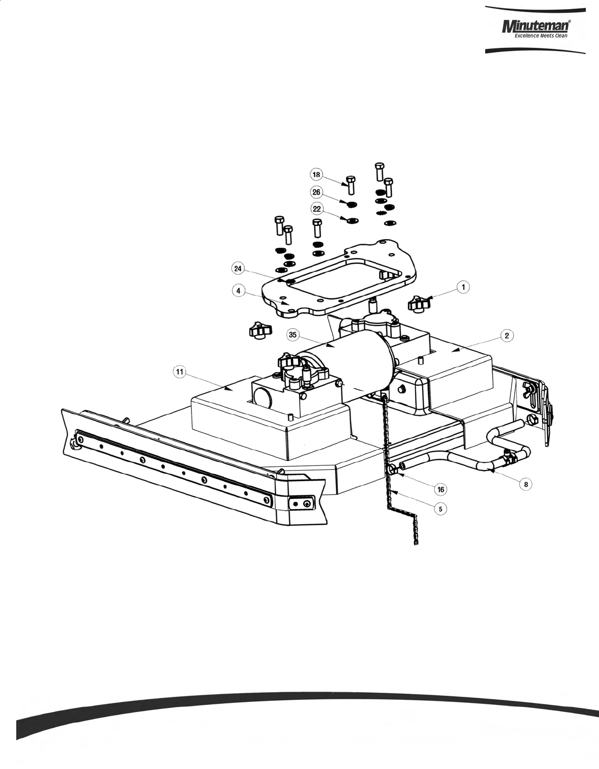
Parts and Instruction Manual
Page 59
24” Disc Scrub Deck Assembly II

Parts and Instruction Manual
Page 60
24” Disc Scrub Deck BOM (See Assembly I & II)
ITEM PART NO. REQ'D DESCRIPTION
1 210118 4 KNOB-3 SIDED 5/16 NYLOC
2 241603 1 RH DISK DECK COVER, SCV2426
3 241605 1 MOTOR SHROUD 24" DECK
4 241610 1 DISK SCRUBDECK MNTG PLATE, 24"
5 241628 1 DRAG CHAIN ASSY, DISK SCRUBDECK SCV 24/26
6 241653 2 WATER FEED BRKT, DISK, SCV24/26
7 241657 2 MOUNTING BRACKET, MOTOR COVER
8 241661 1 SOL. FEED HOSE SUB-ASS'Y, DISK
9 241662 2 COVER MNT BRK'T, SCV 24/26 ASSY
10 241674 1 SIDE SQUEEGEE WIPE ASSY LH, SCV 24/26
11 241685 1 LH DISK DECK COVER, SCV 2426
12 241687 1 SIDE SQUEGEE WIPE ASSY RH, SCV 24/26
13 281611 2 HUB-SCRUB SPACER TUBE
14 281633 2 SPEED NUT - 3/8"
15 281634 2 DISK SOLUTION FEED ASSY
16 450076 2 CRIMP CLAMP SS 185R
17 711231 2 BLT-HH 5/16-18X1.25 ST PL
18 711242 12 BLT-HEX 3/8 -16X1.00 ZP
19 711504 9 WSR-FLAT 1/4 ID SS
20 711506 10 WSR-FLT .344 X .690 X .062 STL ZINC
21 711512 2 WSR-FLAT .75X1.37X.08
22 711515 12 WSR-FLAT .406 X .812 X .0625
23 711516 4 WSR- FLAT .31 X 1.25 X .05
24 711539 2 WSR-EXTERNAL LOCK 3/8
25 711545 2 WSR-HELICAL 5/16
26 711546 12 WSR-HELICAL 3/8
27 711554 2 WSR-INTERNAL LOCK 1/4 ID
28 712140 4 WSR-HELICAL 5/16 SS
29 712157 4 NUT- WING 5/16-18 SS
30 712301 4 WSR-FLAT .87 X .38 X .06
31 712562 8 BOLT-HH 1/4-20X3/4 SS
32 712758 8 WSR-HELICAL 1/4 SS
33 740099 3 CABLE TIE - SMALL
34 748141 1 CABLE WRAP, 11"
35 748210-1 1 DUAL RIGHT ANGLE MOTOR 24" ASSY
36 3312402 2 HUB-SCRUB BRUSH DRIVE
BILL OF MATERIAL - 241601
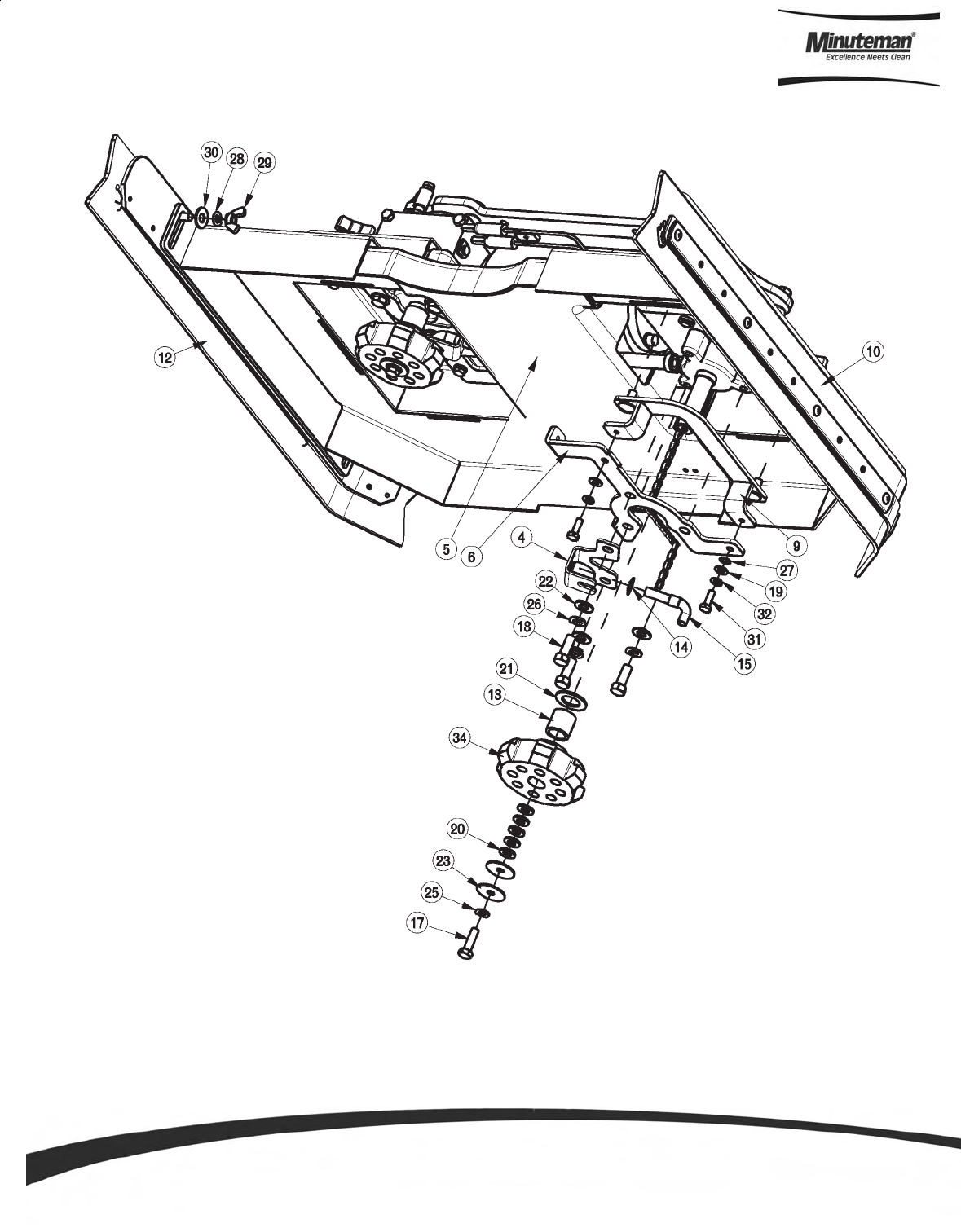
Parts and Instruction Manual
Page 61
26” Disc Scrub Deck Assembly I
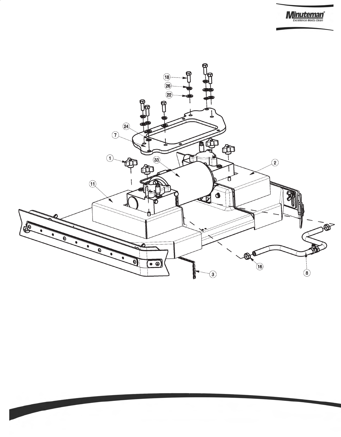
Parts and Instruction Manual
Page 62
26” Disc Scrub Deck Assembly II

Parts and Instruction Manual
Page 63
26” Disc Scrub Deck BOM (See Assembly I & II)
ITEM PART NO. REQ'D DESCRIPTION
1 210118 4 KNOB-3 SIDED 5/16 NYLOC
2 241603 1 RH DISK DECK COVER, SCV2426
3 241628 1 DRAG CHAIN ASSY, DISK SCRUBDECK SCV24/26
4 241653 2 WATER FEED BRKT, DISK, SCV24/26
5 241655 1 MOTOR SHROUD 26" DECK
6 241657 2 MOUNTING BRACKET, MOTOR COVER
7 241660 1 DISK SCRUBDECK MNTG PLATE, 26"
8 241661 1 SOL. FEED HOSE SUB-ASS'Y, DISK
9 241662 2 COVER MNT BRK'T, SCV 24/26 ASSY
10 241674 1 SIDE SQUEEGEE WIPE ASSY LH, SCV 24/26
11 241685 1 LH DISK DECK COVER, SCV 2426
12 241687 1 SIDE SQUEGEE WIPE ASSY RH, SCV 24/26
13 281611 2 HUB-SCRUB SPACER TUBE
14 281633 2 SPEED NUT - 3/8"
15 281634 2 DISK SOLUTION FEED ASSY
16 450076 2 CRIMP CLAMP SS 185R
17 711231 2 BLT-HH 5/16-18X1.25 ST PL
18 711242 12 BLT-HEX 3/8 -16X1.00 ZP
19 711504 9 WSR-FLAT 1/4 ID SS
20 711506 10 WSR-FLT .344 X .690 X .062 STL Z
21 711512 2 WSR-FLAT .75X1.37X.08
22 711515 12 WSR-FLAT .406 X .812 X .0625
23 711516 4 WSR- FLAT .31 X 1.25 X .05
24 711539 2 WSR-EXTERNAL LOCK 3/8
25 711545 2 WSR-HELICAL 5/16
26 711546 12 WSR-HELICAL 3/8
27 711554 2 WSR-INTERNAL LOCK 1/4 ID
28 712140 4 WSR-HELICAL 5/16 SS
29 712157 4 NUT- WING 5/16-18 SS
30 712301 4 WSR-FLAT .37 X .87 X .06
31 712562 8 BOLT-HH 1/4-20X3/4 SS
32 712758 8 WSR-HELICAL 1/4 SS
33 748211-1 1 DUAL RIGHT ANGLE MOTOR 26" ASSY
34 3312402 2 HUB-SCRUB BRUSH DRIVE
BILL OF MATERIAL - 241651
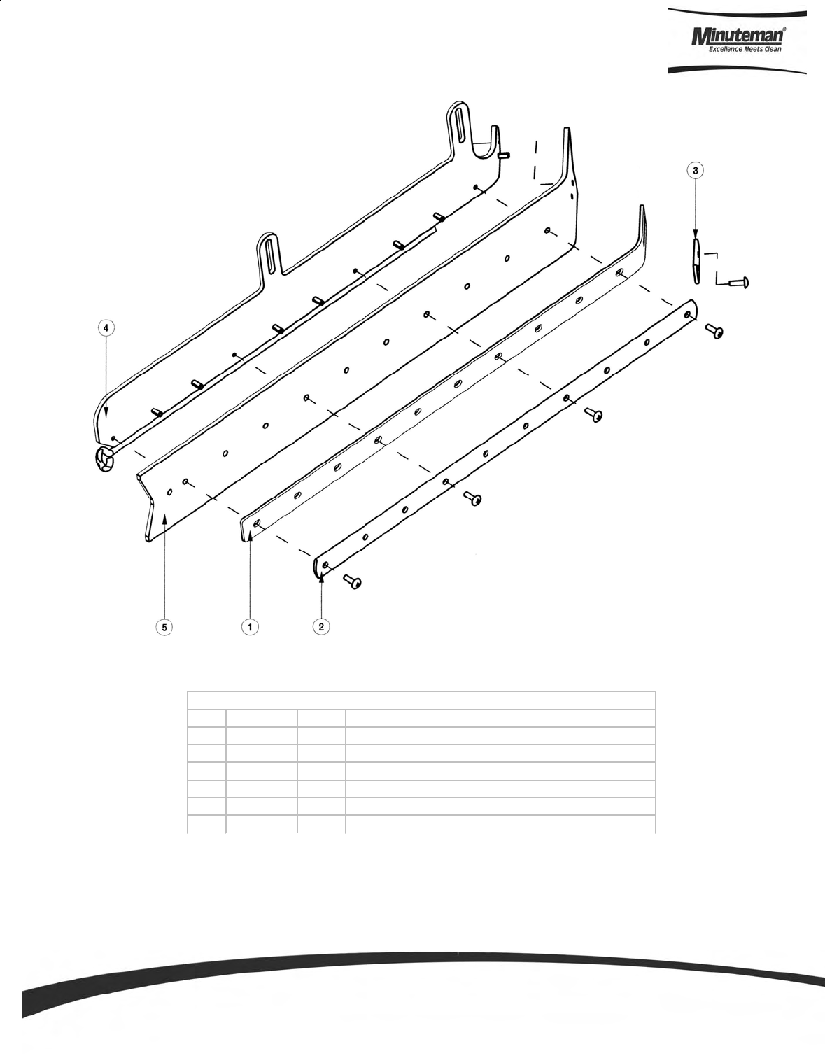
Parts and Instruction Manual
Page 64
Cylindrical Side Squeegee (Left Hand Side)
ITEM PART NO. REQ'D DESCRIPTION
1 241678 1 BACKER BLADE, LONG SCV 24/26
2 241679 1 RETAINER-LONG SIDE SQ SCV 24/26
3 241680 1 SHORT RETAINER, SIDE SQ SCV 24/26
4 241917 1 SIDE SQUEEGEE SUB-ASSY LH, SCV 24/26
5 241925 1 SIDE SQUEEGEE BLADE LINATEX, SCV 24/26
6 710154 5 SCR-MC TR HD 10-32 X .625 SS
BILL OF MATERIAL - 241915
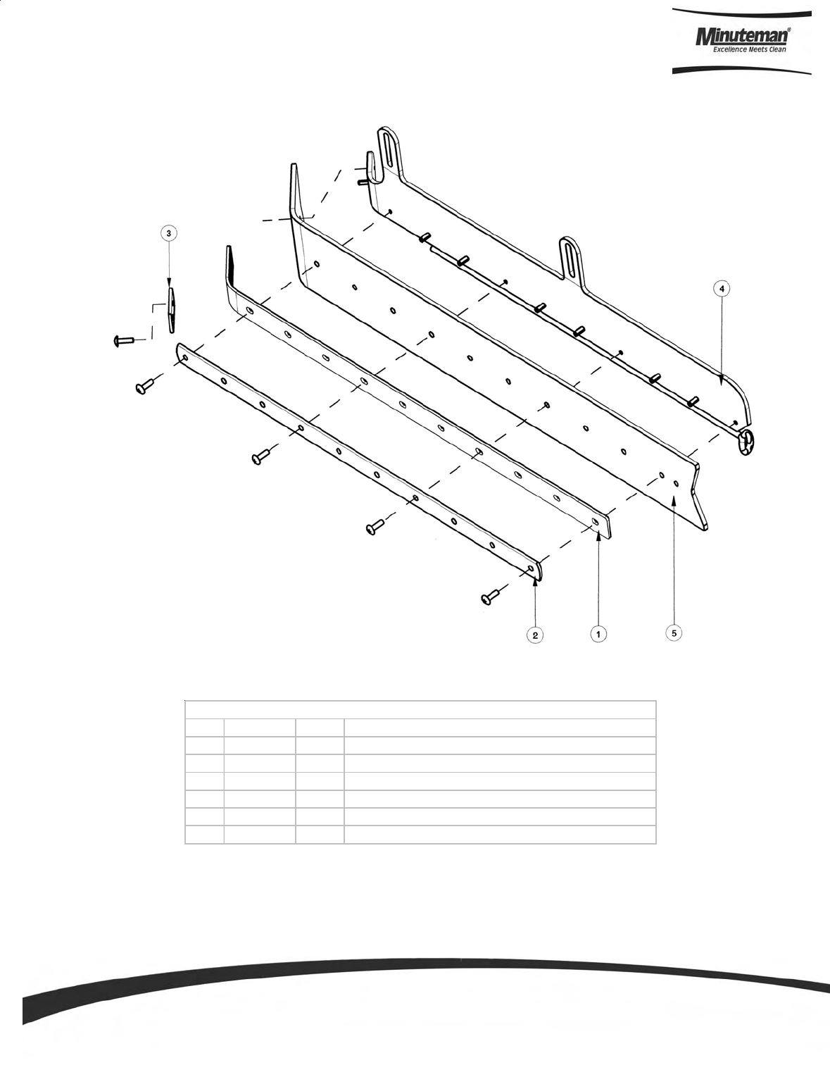
Parts and Instruction Manual
Page 65
Cylindrical Side Squeegee (Right Hand Side)
ITEM PART NO. REQ'D DESCRIPTION
1 241678 1 BACKER BLADE, LONG SCV 24/26
2 241679 1 RETAINER-LONG SIDE SQ SCV 24/26
3 241680 1 SHORT RETAINER, SIDE SQ SCV 24/26
4 241918 1 SIDE SQUEEGEE SUB-ASSY RH, SCV 24/26
5 241925 1 SIDE SQUEEGEE BLADE LINATEX, SCV 24/26
6 710154 5 SCR-MC TR HD 10-32 X .625 SS
BILL OF MATERIAL - 241916
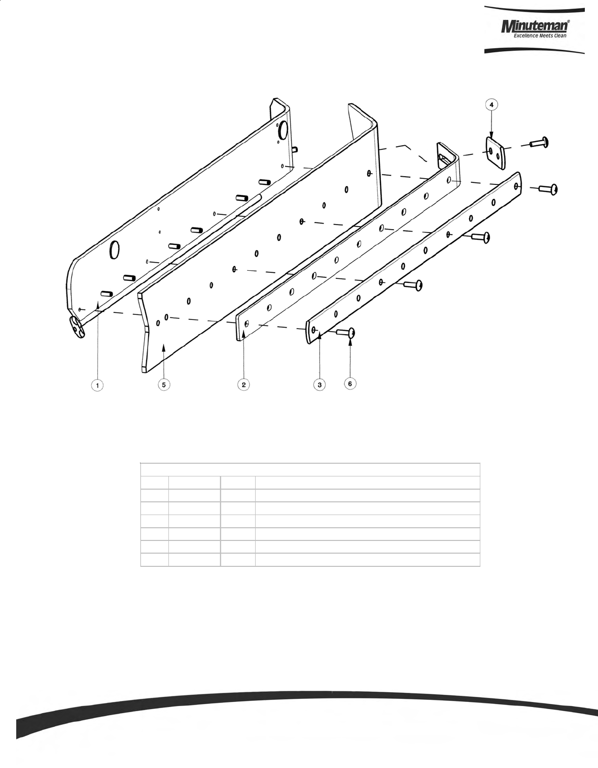
Parts and Instruction Manual
Page 66
Disc Side Squeegee (Left Hand Side)
ITEM PART NO. REQ'D DESCRIPTION
1 241675 1 DISK SQUEEGEE SUB-ASSY LH, SCV 24/26
2 241678 1 BACKER BLADE, LONG SCV 24/26
3 241679 1 RETAINER-LONG SIDE SQ SCV 24/26
4 241680 1 SHORT RETAINER, SIDE SQ SCV 24/26
5 241925 1 SIDE SQUEEGEE BLADE LINATEX, SCV 24/26
6 710154 5 SCR-MC TR HD 10-32 X .625 SS
BILL OF MATERIAL - 241674
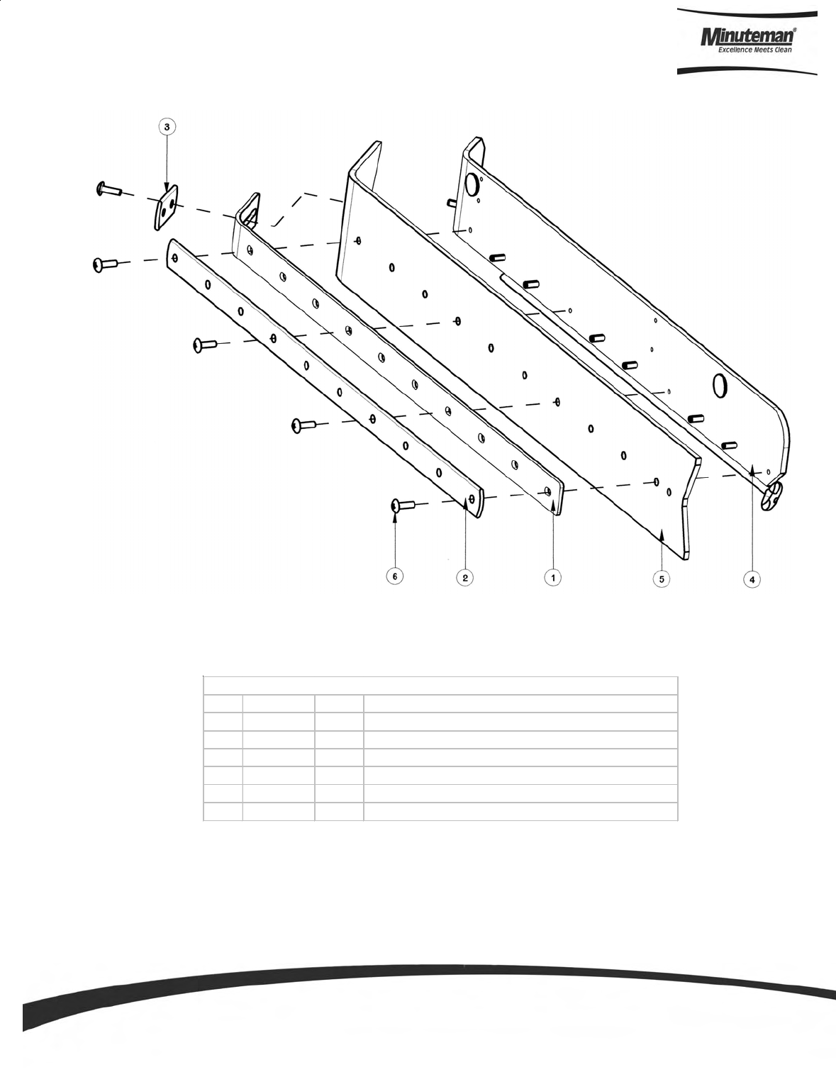
Parts and Instruction Manual
Page 67
Disc Side Squeegee (Right Hand Side)
ITEM PART NO. REQ'D DESCRIPTION
1 241678 1 BACKER BLADE, LONG SCV 24/26
1 241679 1 RETAINER-LONG SIDE SQ SCV 24/26
1 241680 1 SHORT RETAINER, SIDE SQ SCV 24/26
1 241688 1 DISK SQUEEGEE SUB-ASSY RH, SCV 24/26
1 241925 1 SIDE SQUEEGEE BLADE LINATEX, SCV 24/26
1 710154 5 SCR-MC TR HD 10-32 X .625 SS
BILL OF MATERIAL - 241687
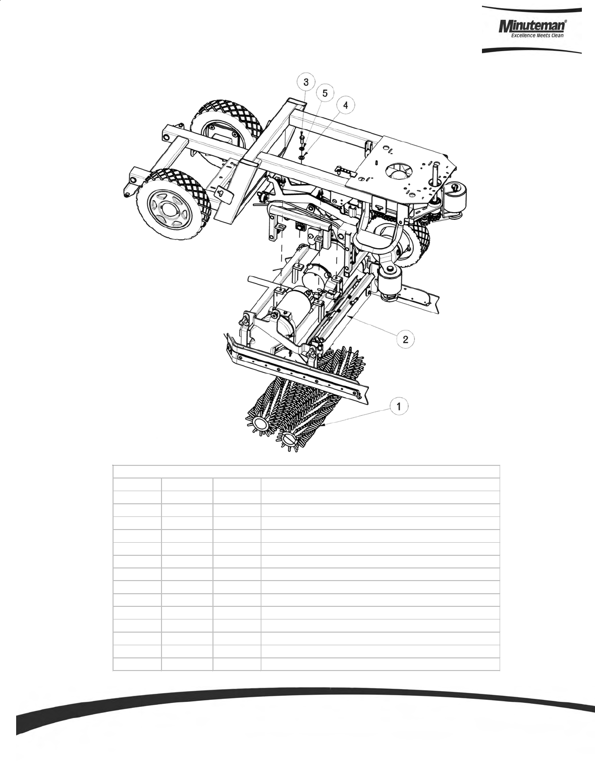
Parts and Instruction Manual
Page 68
24” Cylindrical Brush Assembly
ITEM PART NO. REQ'D DESCRIPTION
1 241520 2 BRUSH, CYL 24" .022 NYLON
1A 241521 2 BRUSH, CYL 24" .028 NYLON
1B 241522 2 BRUSH, CYL 24" .026 PP
1C 241523 2 BRUSH, CYL 24" .028 PP
1D 241524 2 BRUSH, CYL 24" DYNASCRUB 500GR
1E 241525 2 BRUSH, CYL 24" POWERSCRUB 120GR
1F 241526 2 BRUSH, CYL 24" NYLOGRIT 80GR
1G 241527 2 BRUSH, CYL 24" STRATAGRIT 46GR
1H 241528 2 BRUSH, CYL 24" STRGRIT PLUS 36
1I 241529 2 BRUSH, CYL 24" 180 GR
2 241702 1 24" CYL DECK W/ SIDE SQUEEGEES, SCV 24/26
3 711242 4 BLT-HEX 3/8-16X1.00 ZP
4 711515 4 WSR-FLAT .406 X .812 X .0625
5 711546 4 WSR-HELICAL 3/8
BILL OF MATERIAL
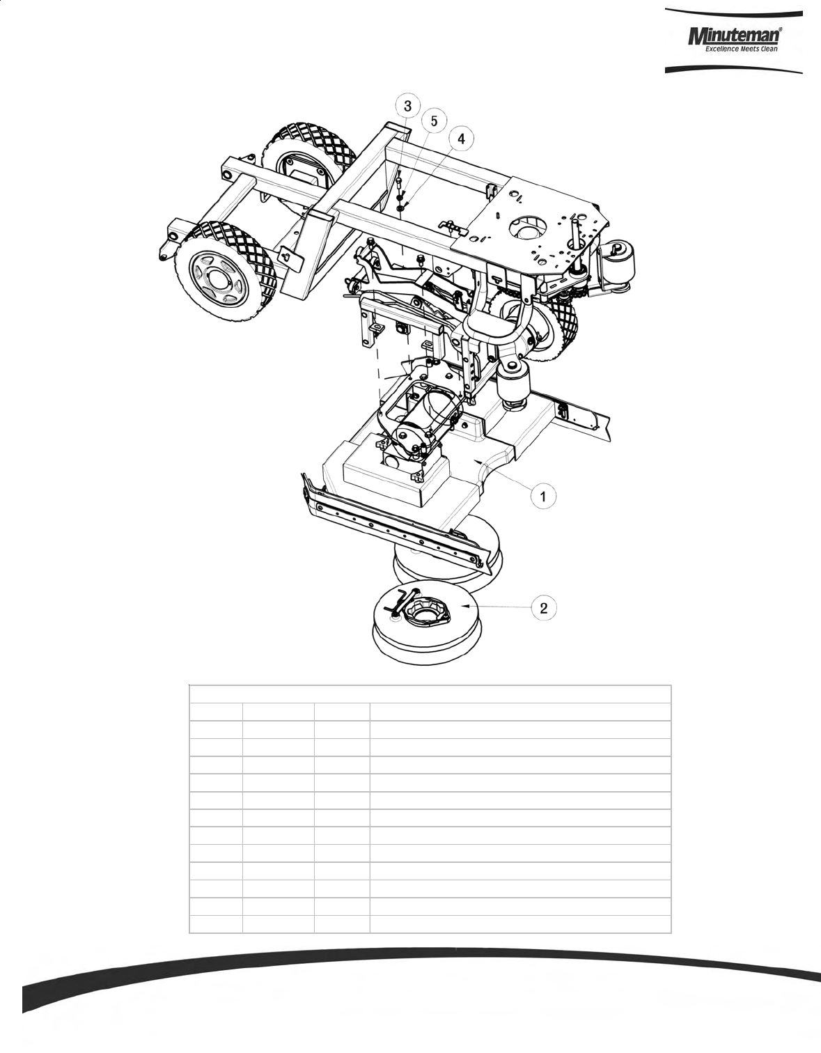
Parts and Instruction Manual
Page 69
ITEM PART NO. REQ'D DESCRIPTION
1 241601 1 DISK SCRUBDECK, 24"
2 241618 2 BRUSH - 12" PWR DRIVE W/ PAD HOLDER
2A 241620 2 12" SCRUB BRUSH .022 NYLON
2B 241621 2 12" SCRUB BRUSH .028 NYLON
2C 241622 2 12" SCRUB BRUSH DYNASCRUB 500GR
2D 241623 2 12" SCRUB BRUSH POWERSCRUB 120GR
2E 241624 2 12" SCRUB BRUSH NYLOGRIT 80GR
2F 241625 2 12" SCRUB BRUSH STRATAGRIT 46GR
2G 241626 2 12" SCRUB BRUSH 180GR
3 711242 4 BLT-HEX 3/8-16X1.00 ZP
4 711515 4 WSR-FLAT .406 X .812 X .0625
5 711546 4 WSR-HELICAL 3/8
BILL OF MATERIAL
24” Disc Brush Assembly
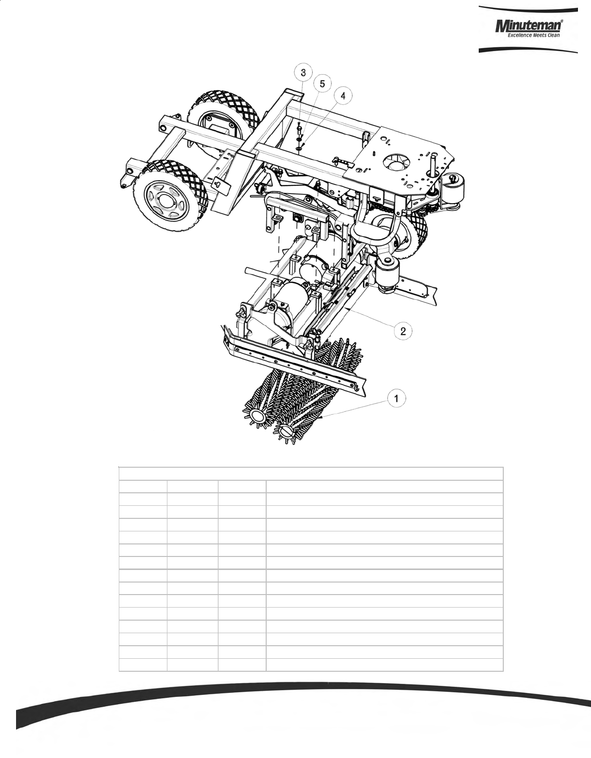
Parts and Instruction Manual
Page 70
26” Cylindrical Brush Assembly
ITEM PART NO. REQ'D DESCRIPTION
1 241530 2 BRUSH, CYL 26" .022 NYLON
1A 241531 2 BRUSH, CYL 26" .028 NYLON
1B 241532 2 BRUSH, CYL 26" .026 PP
1C 241533 2 BRUSH, CYL 26" .028 PP
1D 241534 2 BRUSH, CYL 26" DYNASCRUB 500GR
1E 241535 2 BRUSH, CYL 26" POWERSCRUB 120GR
1F 241536 2 BRUSH, CYL 26" NYLOGRIT 80GR
1G 241537 2 BRUSH, CYL 26" STRATAGRIT 46GR
1H 241538 2 BRUSH, CYL 26" STRGRIT PLUS 36
1I 241539 2 BRUSH, CYL 26" 180 GR
2 241703 1 26" CYL DECK W/ SIDE SQUEEGEES, SCV 24/26
3 711242 4 BLT-HEX 3/8-16X1.00 ZP
4 711515 4 WSR-FLAT .406 X .812 X .0625
5 711546 4 WSR-HELICAL 3/8
BILL OF MATERIAL

Parts and Instruction Manual
Page 71
26” Disc Brush Assembly
ITEM PART NO. REQ'D DESCRIPTION
1 241651 1 DISK SCRUBDECK, 26"
2 241619 2 BRUSH - 13" PWR DRIVE W/ PAD HOLDER
2A 241630 2 13" SCRUB BRUSH .022 NYLON
2B 241631 2 13" SCRUB BRUSH .028 NYLON
2C 241632 2 13" SCRUB BRUSH DYNASCRUB 500GR
2D 241633 2 13" SCRUB BRUSH POWERSCRUB 120GR
2E 241634 2 13" SCRUB BRUSH NYLOGRIT 80GR
2F 241635 2 13" SCRUB BRUSH STRATAGRIT 46GR
2G 241636 2 13" SCRUB BRUSH 180GR
3 711242 4 BLT-HEX 3/8-16X1.00 ZP
4 711515 4 WSR-FLAT .406 X .812 X .0625
5 711546 4 WSR-HELICAL 3/8
BILL OF MATERIAL
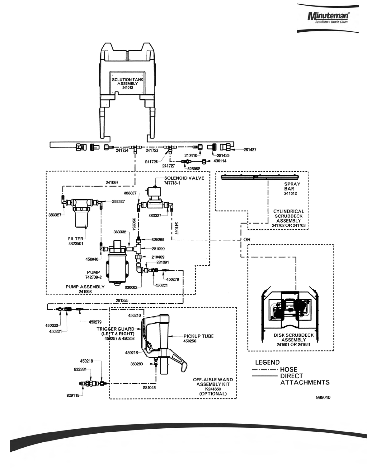
Parts and Instruction Manual
Page 72
Plumbing Diagram
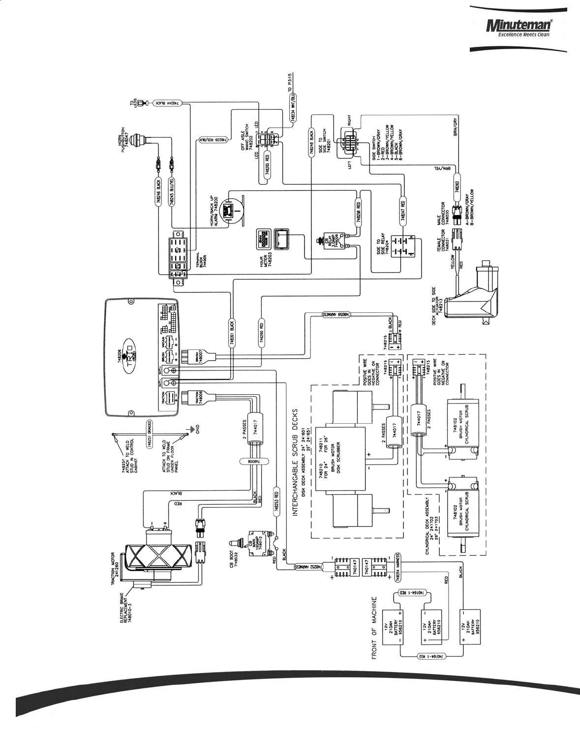
Parts and Instruction Manual
Page 73
Wiring Diagrams
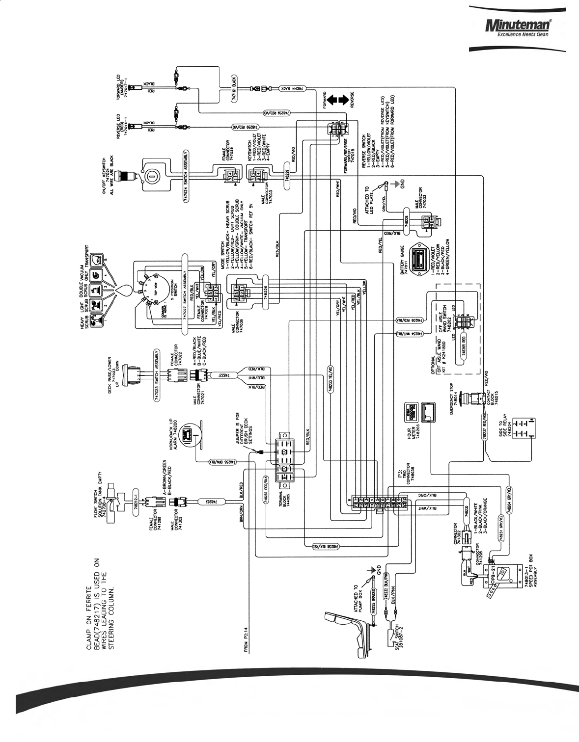
Parts and Instruction Manual
Page 74
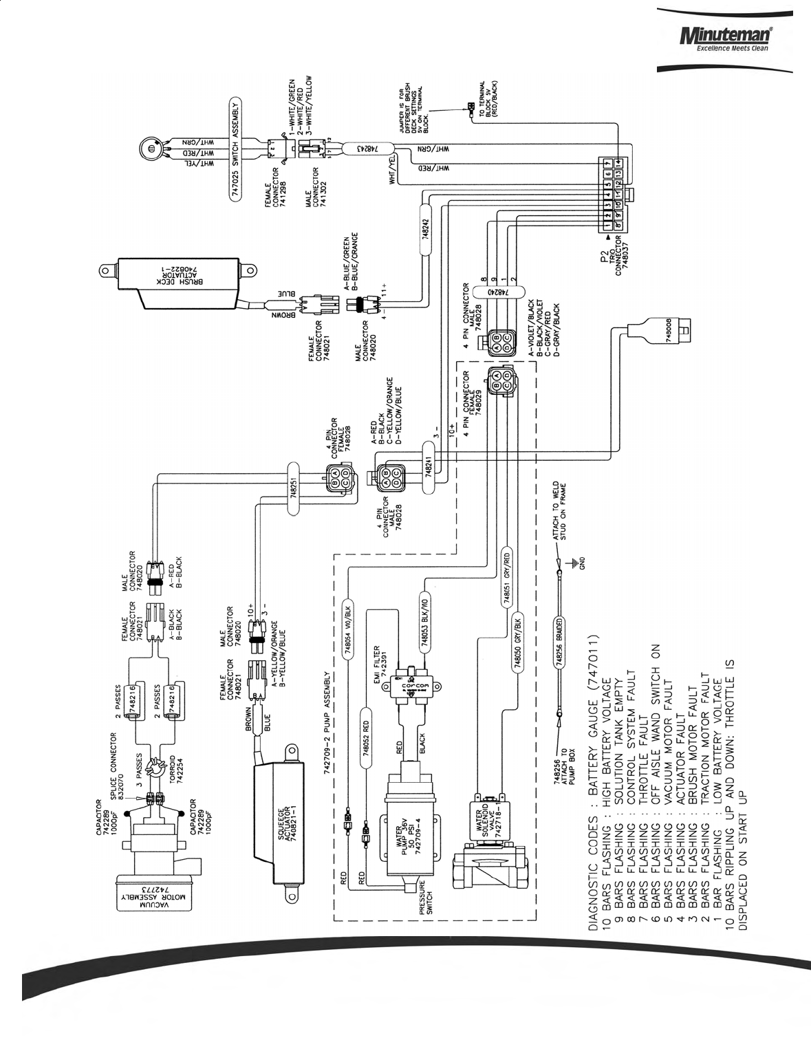
Parts and Instruction Manual
Page 75
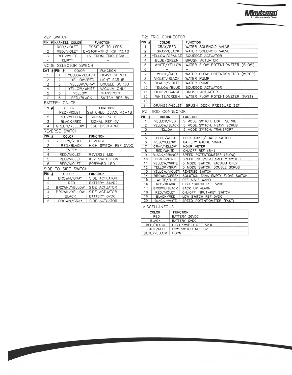
Parts and Instruction Manual
Page 76

Minuteman International Made Simple Commercial Limited Warranty
Minuteman International, Inc. warrants to the original purchaser/user that the product is free from defects in
workmanship and materials under normal use. Minuteman will, at its option, repair or replace without charge, parts
that fail under normal use and service when operated and maintained in accordance with the applicable operation and
instruction manuals. All warranty claims must be submitted through and approved by factory authorized repair
stations.
This warranty does not apply to normal wear, or to items whose life is dependent on their use and care, such as belts,
cords, switches, hoses, rubber parts, electrical motor components or adjustments. Parts not manufactured by
Minuteman are covered by and subject to the warranties and/or guarantees of their manufacturers. Please contact
Minuteman for procedures in warranty claims against these manufacturers.
Special warning to purchaser -- Use of replacement filters and/or prefilters not manufactured by Minuteman or its
designated licensees, will void all warranties expressed or implied. A potential health hazard exits without original
equipment replacement.
All warranted items become the sole property of Minuteman or its original manufacturer, whichever the case may be.
Minuteman disclaims any implied warranty, including the warranty of merchantability and the warranty of fitness for a
particular purpose. Minuteman assumes no responsibility for any special, incidental or consequential damages.
This limited warranty is applicable only in the U.S.A. and Canada, and is extended only to the original user/purchaser
of this product. Customers outside the U.S.A. and Canada should contact their local distributor for export warranty
policies. Minuteman is not responsible for costs or repairs performed by persons other than those specifically
authorized by Minuteman. This warranty does not apply to damage from transportation, alterations by unauthorized
persons, misuse or abuse of the equipment, use of non-compatible chemicals, or damage to property, or loss of
income due to malfunctions of the product.
If a difficulty develops with this machine, you should contact the dealer from whom it was purchased.
This warranty gives you specific legal rights, and you may have other rights which vary from state to state. Some
states do not allow the exclusion or limitation of special, incidental or consequential damages, or limitations on how
long an implied warranty lasts, so the above exclusions and limitations may not apply to you.
Cord Electric Group………. Three years parts, two years labor, ninety days travel (Not to exceed two hours)
Exceptions………. Port-A-Scrub, one year parts, six months labor
MPV 13, one year parts
MPV 14 and 18, two years parts, one year labor
RapidAir blower, one year parts, one year labor
Explosion-Proof Vacuum, one year parts, one year labor
Pneumatic Vacuums, three years parts, one year labor
EX 12 and EX12H, one year parts, one year labor
Battery Operated Group….. Three years parts, two years labor, ninety days travel
(Not to exceed two hours)
Exceptions……Sweepers, one year parts, one year labor, ninety days travel
(Not to exceed two hours)
Internal Combustion Group….One year parts, one year labor, ninety day travel
(Not to exceed two hours)
Replacement Parts……………..Ninety days
Batteries………………………….0-3 months replacement, 4-12 months pro-rate
Polypropylene Plastic Tanks…Ten years, no additional labor
111 South Rohlwing Road · Addison, Illinois 60101 USA
Phone 630- 627-6900 · Fax 630- 627-1130
E-Mail, www.minutemanintl.com
A Member of the Hako Group
987597
REV G 09/07
