Powerboss Admiral 48 Ride On Sweeper Scrubber Operators Manual
Powerboss-Admiral-48-Ride-On-Sweeper-Scrubber-Operators-Manual powerboss-admiral-48-ride-on-sweeper-scrubber-operators-manual powerboss-admiral-48-ride-on-sweeper-scrubber-operators-manual 2011 file product_file sweepscrub
2017-01-12
: Sweepscrub Powerboss-Admiral-48-Ride-On-Sweeper-Scrubber-Operators-Manual powerboss-admiral-48-ride-on-sweeper-scrubber-operators-manual 2010 file product_file
Open the PDF directly: View PDF ![]() .
.
Page Count: 120 [warning: Documents this large are best viewed by clicking the View PDF Link!]
- Introduction
- Preface
- Intended use
- Notes on warranty
- Acceptance of the machine
- 1 Safety Information
- 2 Starting Up
- 3 Operation
- 4 Technical Data
- 5 Maintenance and Service
- PowerBoss Warranty
- notes

Instruction Manual
Admiral 48D (7580.45)

2
Introduction
Preface
Dear Customer,
We are certain that the excellent
qualities of the vehicle will justify the
faith you have shown in us through your
purchase.
Your safety, and that of others,
basically lies in your ability to control
and operate the vehicle. Before using
the vehicle for the first time, read this
translation of the original manual
thoroughly, act according to the
information contained and keep it in a
safe place for future reference or
subsequent owners. Please read the
Chapter "Safety Information" prior to
starting the vehicle to ensure it is
operated and used safely.
The operating manual contains all the
most important information regarding
operation, maintenance and service.
Throughout this manual, texts which
concern safety are indicated by the
corresponding danger pictogram.
Should you have any questions in
respect of the vehicle or operating
instruction manual, your authorized
PowerBoss dealer is available to
provide help at any time.
We explicitly point out that no legal
claims may be asserted based on the
information contained in this manual.
Please pay attention that only original
spare parts are used for any necessary
maintenance and repair work. Only
original spare parts can guarantee long,
reliable equipment operation. We
reserve the right to make technical
improvements.
Valid from: January 2012
PowerBoss Inc.
175 Anderson Street
NC 28315 U.S.A.
Telephone: (910) 944-2105
Fax: (910) 944-740
Intended use
The Admiral 48D is a scrubber-drier
vehicle conceived for wet cleaning hard
floors indoors. Any use beyond this is
regarded as improper use. The
manufacturer is not considered liable
for any damage resulting from improper
use; the user is solely responsible for all
the risks.
The scrubber-drier has not
been approved for use on
public paths and roads.
Intended use also includes maintaining
and observing the operating,
maintenance and repair conditions
prescribed by the manufacturer.
The scrubber-drier may only be
operated, serviced and repaired by
personnel who are familiar with the
work involved and are aware of the
risks.
The applicable accident prevention
laws must be observed and any
generally accepted health and safety
directives must be maintained.
Based on the conception, design and
construction of the vehicle introduced
onto the market by us, the vehicle
complies with the applicable basic
Introduction

3
safety and health requirements
stipulated in the EC Directive (refer to
the Declaration of Conformity). This
declaration is no longer considered
valid in the event of modifications to the
vehicle not authorized by us. The
manufacturer is not deemed liable for
any damage resulting from
unauthorized modifications to the
vehicle.
Notes on warranty
The terms defined in the purchase
agreement apply. Claims for
compensation related to damage are
excluded from the terms of warranty
when the damage is the result of failure
to observe regulations concerning
service and maintenance. Maintenance
work must be performed by authorized
PowerBoss service centers and
confirmed in the “Maintenance Report”
which serves as a warranty logbook.
The following are excluded from the
terms of warranty: wear and tear
through overuse, defective fuses,
improper handling and use or
unauthorized modifications. Claims
under the terms of warranty are
annulled when damage occurs to the
vehicle resulting from the use of parts or
accessories not explicitly approved by
us or from failure to observe
maintenance regulations.
Acceptance of the machine
Inspect the vehicle immediately on
delivery for signs of transport damage.
It will be replaced when the damage is
immediately confirmed by the haulage
contractor and the damage report is
sent to our authorized sales partner
together with the consignment note.
Introduction

4
Contents
Introduction . . . . . . . . . . . . . 2
Preface. . . . . . . . . . . . . . . . . . 2
Intended use. . . . . . . . . . . . . . 2
Notes on warranty . . . . . . . . . 3
Acceptance of the machine . . 3
1 Safety Information . . . . . . . . 6
1.1 Safety and warning symbols . 6
1.2 General information . . . . . . . . 7
1.3 Operating information. . . . . . . 8
1.4 Maintenance information . . . 10
1.5 Particular risks . . . . . . . . . . . 12
1.5.1 Electronics . . . . . . . . . . . . . . 12
1.5.2 Batteries . . . . . . . . . . . . . . . . 12
1.6 Environmental protection . . . 13
1.7 Labels on the vehicle . . . . . . 14
2 Starting Up . . . . . . . . . . . . . 18
2.1 Instruction. . . . . . . . . . . . . . . 18
2.2 Initial battery charge. . . . . . . 18
2.3 Prior to starting up
for the first time. . . . . . . . . . . 19
2.3.1 Installing brushes and pads . 19
2.3.2 Installing and adjusting
the squeegee . . . . . . . . . . . . 24
2.3.3 Adjusting the driver's seat . . 25
2.4 Before starting up daily. . . . . 26
3 Operation . . . . . . . . . . . . . . 27
3.1 Method of operation . . . . . . . 27
3.1.1 Pre-sweep/vacuum unit . . . . 27
3.1.2 Scrubbing unit . . . . . . . . . . . 28
3.1.3 Squeegee. . . . . . . . . . . . . . . 29
3.1.4 Suction turbines (suction). . . 29
3.1.5 Fresh water tank. . . . . . . . . . 30
3.1.6 Recovery tank . . . . . . . . . . . 31
3.1.7 Traction drive . . . . . . . . . . . . 32
3.1.8 Brakes . . . . . . . . . . . . . . . . . 32
3.1.9 Batteries and charger. . . . . . 33
3.1.10 Options. . . . . . . . . . . . . . . . . 35
3.2 Operating and
indicator elements . . . . . . . . 39
3.2.1 Operating elements
in the driver's cab . . . . . . . . . 39
3.2.2 Left-hand
operating panel. . . . . . . . . . . 42
3.2.3 Right-hand
operating panel. . . . . . . . . . . 48
3.2.4 Operating elements
on the vehicle . . . . . . . . . . . . 52
3.3 Operation . . . . . . . . . . . . . . . 56
3.3.1 Switching the vehicle on. . . . 56
3.3.2 Accelerating . . . . . . . . . . . . . 57
3.3.3 Stopping and parking . . . . . . 57
3.3.4 Cleaning . . . . . . . . . . . . . . . . 57
3.3.5 Switching the vehicle off. . . . 61
3.3.6 Loading and
transporting the vehicle . . . . 61
3.4 After finishing work. . . . . . . . 62
3.5 Function faults . . . . . . . . . . . 63
3.5.1 Error code table . . . . . . . . . . 63
3.5.2 Other function faults . . . . . . . 65
4 Technical Data . . . . . . . . . . 66
5 Maintenance
and Service . . . . . . . . . . . . . 75
5.1 PowerBoss
system maintenance . . . . . . 75
5.2 Maintenance report . . . . . . . 76
5.3 Maintenance schedule . . . . . 77
5.3.1 PowerBoss system
maintenance, customer . . . . 77
5.3.2 PowerBoss
system maintenance I . . . . . 80
5.3.3 PowerBoss
system maintenance II . . . . . 84
5.3.4 PowerBoss system
maintenance III/S
(safety check). . . . . . . . . . . . 85

5
Contents
5.4 Battery system . . . . . . . . . . . 86
5.4.1 Charging batteries . . . . . . . . 87
5.4.2 Servicing the
driving batteries . . . . . . . . . . 88
5.4.3 Disassembling
the battery . . . . . . . . . . . . . . 88
5.4.4 Installing the battery . . . . . . . 90
5.4.5 Disposing of batteries. . . . . . 90
5.4.6 Deep discharge
signal transducer (BMS). . . . 91
5.5 Fresh water tank. . . . . . . . . . 92
5.5.1 Filling
the fresh water tank . . . . . . . 93
5.5.2 Emptying
the fresh water tank . . . . . . . 94
5.5.3 Cleaning
the draining hose cap. . . . . . 94
5.5.4 Cleaning
the fresh water filter . . . . . . . 94
5.6 Recovery tank . . . . . . . . . . . 95
5.6.1 Emptying
the recovery tank . . . . . . . . . 96
5.6.2 Cleaning
the recovery tank . . . . . . . . . 96
5.6.3 Cleaning
the draining hose cap. . . . . . 97
5.6.4 Cleaning
the air intake filter. . . . . . . . . 98
5.6.5 Cleaning the openings
to the fresh water tank . . . . . 98
5.7 Scrubbing unit . . . . . . . . . . . 99
5.7.1 Changing the brushes . . . . . 99
5.7.2 Installing new
rubber deflector strips. . . . . 100
5.8 Squeegee. . . . . . . . . . . . . . 101
5.8.1 Cleaning the squeegee . . . 101
5.8.2 Disassembling
the squeegee . . . . . . . . . . . 101
5.8.3 Installing the squeegee . . . 102
5.8.4 Changing
the sealing strips . . . . . . . . 102
5.8.5 Adjusting
the support rollers. . . . . . . . 103
5.9 Pre-sweep/Vacuum unit . . . 104
5.9.1 Emptying the dirt hopper . . 104
5.9.2 Dust vacuum . . . . . . . . . . . 105
5.9.3 Side brushes . . . . . . . . . . . 106
5.9.4 Cylindrical brush. . . . . . . . . 107
5.10 Wheels . . . . . . . . . . . . . . . . 111
5.10.1 Changing the rear wheels . 111
5.10.2 Changing the front wheel . . 111
5.11 Electrical installation. . . . . . 112
5.11.1 Red control lamps . . . . . . . 112
5.11.2 Error codes. . . . . . . . . . . . . 112
5.11.3 Fuses . . . . . . . . . . . . . . . . . 112
5.11.4 Drive control relay . . . . . . . 112
5.12 Cleaning the vehicle. . . . . . 113
5.13 Transport and towing . . . . . 114
PowerBoss Warranty . . . . 116

6
Safety Information
1 Safety Information
1.1 Safety and warning symbols
All texts related to personal safety,
safety of the vehicle and environmental
protection are assigned the following
symbols throughout the operating
manual:
Symbol Risks to ... Definition
Safety information persons
or property Safety information to prevent the development of
hazardous situations resulting from ignoring or failing
to follow instructions or prescribed work procedures.
Note the machine Important information on handling the equipment in
order to maintain its functionality.
Ecological hazard the environment Ecological hazard through the use of substances
which represent a potential hazard to health and the
environment.

7
Safety Information
1.2 General information
• The scrubber-drier fulfills all the
applicable safety and health
requirements stipulated in the EC
directives with regard to its planning,
constructional design and final
construction as introduced by us
onto the market. In the case of
modifications to the vehicle not
approved by us, the EC Declaration
of Conformity enclosed in this
operating manual loses its validity.
• In addition to the information
provided in this operating manual, all
the legally applicable health and
safety provisions must be observed.
• Before starting up the vehicle for the
first time, read the operating manual
supplied with it thoroughly as well as
any separate manuals provided with
additional or attachment devices and
observe all the information during
work.
• The vehicle may only be operated,
maintained and repaired by persons
trained by PowerBoss or authorized
to do so by PowerBoss.
• Particular attention should be paid to
the information regarding safety.
Technical expertise is the key to
preventing errors when operating the
equipment and ensuring trouble-free
operation.
• The operating manual must always
be kept at the operating location of
the vehicle and, as a result, should
be kept in a safe place on the
vehicle.
• If the equipment is sold or rented out,
these documents should be
transferred to the new
owner/operator. The transfer should
be confirmed!
• The warning labels attached to the
equipment provide important
information concerning safe
operation. Labels which are illegible
or missing must be replaced.
• Original spare parts must be used to
ensure safety.
• If you want to shut the vehicle down,
render it inoperable. It must not
represent a source of danger for
children.
• The positional information "left" and
"right" always related to looking to
the front when in the vehicle.

8
Safety Information
1.3 Operating information
• Before starting the vehicle up for the
first time, the battery to be used must
be fully charged, properly, by
implementing the initial battery
charge routine. Please pay attention
to the operating manual provided
with the charging unit as well as the
manual from the battery
manufacturer. PowerBoss assumes
no liability for damage to the battery
caused by a fault when the battery is
charged for the first time.
• Before starting the vehicle up,
always check it is in a proper
condition and that it is safe to drive
and operate. Clear up any faults and
defects immediately! Never operate
the vehicle without functional safety
equipment.
• Warning: Do not use the vehicle
without a protective roof structure
(refer to "Accessories", "Cab safety
roof") in areas in which the driver is
at risk of being hit by falling objects
(e.g. warehouses). Contact the trade
association responsible for you as to
whether obligations exist in this
respect.
• The scrubber-drier must be
subjected to an inspection in respect
of its operationally safe condition at
least once a year by an authorized
technical expert. The results of the
inspection must be documented in
writing and kept safe at least until the
next inspection.
• Floor cleaning machines may only
be operated by suitable personnel
who have been trained to operate
the equipment, have proven their
capability to operate the vehicle to
the contractor or person appointed
by him and have been explicitly
charged by him to operate the
vehicle.
• Before starting work, operating
personnel must be fully familiar with
all adjustment, operating and control
elements as well as their respective
function! It is too late to do this when
the vehicle is actually in operation!
• The warning labels attached to the
scrubber-drier provide important
information concerning safe
operation.
• Wet floors are a potential risk for
slipping! Ensure to provide the
corresponding information and
warning signs.
• If the floor is excessively wet, check
the vehicle for leaks and that the
sealing strips are in a good
condition. If the sealing strips are
damaged, change them
immediately.
• Only use cleaning agents suitable for
the vendor (non-foaming) and
observe all the use, disposal and
warning information provided by the
cleaning agent manufacturer.
• It is forbidden to use the vehicle in
potentially explosive atmospheres.
• The vehicle is not suitable for
clearing up health-hazardous,
inflammable or explosive fluids or
dusts and substances with similar
properties.
• Ride-on equipment may only be set
into motion from the seat (seat
contact switch).
• The seat contact switch must never
be bypassed or the function
immobilized in any way (e.g. by
placing a heavy load on the seat).
• It is forbidden to transport people on
the vehicle!
• Always wear heavy duty, non-slip
footwear when working with the
vehicle.

9
Safety Information
• Start driving immediately after
switching on the brush head drive
otherwise the brush could produce
impressions on the floor.
• The machine may only be driven on
and the equipment used on those
surfaces which have been approved
by the contractor or person
appointed by him.
• The manner of driving must be
adapted to the local conditions (floor
characteristics, presence of persons
in the vicinity, obstacles, etc.).
• When using the vehicle, it is
essential to pay attention to third
parties, especially children.
• Never leave the vehicle unattended
while motors are still running and it
has not been locked against
unintended movement.
• To prevent authorized use of the
vehicle, lock the drive by removing
the key from the key switch.
• When transporting the vehicle, the
motors must be shutdown.
• Only open empty recovery tanks.
• The scrubber-drier may only be
driven on hard-surfaced, sufficiently
non-slip ground (e.g. asphalt,
concrete) which is free of oil, water,
snow etc.
• The vehicle may only be driven on
gradients to a maximum of 6% for a
maximum of three minutes when in
work mode. Do not drive the vehicle
on slopes with a gradient steeper
than the limit gradient indicated on
the vehicle.
The climbing capacities
stipulated in this manual can
and may only be achieved with
the battery specified in the
Section „Technical Data“.
When cleaning on slopes, the
traction may be restricted.
• When driving to its place of
deployment (transport mode), the
vehicle may only be driven on
gradients to a maximum of 15% for a
maximum of 15 seconds. When
driving the vehicle in transport mode,
the ground must be clean and dry,
i.e. free of dirt, oil, snow, water etc.,
particularly when driving on
gradients.

10
Safety Information
1.4 Maintenance information
Properly completed vehicle
maintenance is an important measure
in preventing accidents.
• The maintenance work and
maintenance intervals prescribed in
the operating manual must be
adhered to.
• Operating personnel must complete
the necessary daily and weekly
maintenance work. All other
maintenance work must be
completed at your nearest
authorized PowerBoss service
center.
• Before starting any cleaning and
maintenance work or replacing
parts, switch off the motors, remove
the key from the key switch and pull
out the battery plug. This is
particularly important in respect of
work on the electrical system!
• Before working on the brushes,
switch off the scrubbing unit, set the
key switch to position 0 and remove
the key.
• The scrubbing unit may only be
disassembled and installed by
service personnel.
• Suitable tools must be used for
cleaning and maintenance work.
• Spare parts must comply with the
minimum technical requirements
stipulated by the manufacturer! This
is ensured by the use of original
spare parts.
• When working in the area of the
raised seat console, it must be
pivoted up fully to prevent it
accidentally closing or suddenly
slamming shut.
• It is not permitted to clean the vehicle
with a pressure washer or steam
blaster.
• Clean the recovery tank regularly to
protect it from the accumulation of
dirt, viruses, bacteria, etc.
• It is not permitted to use aggressive
and corrosive cleaning agents.
• Allow the vehicle to dry after being
cleaned, e.g. over the weekend.
• The vehicle must be checked by a
recognized technical expert in
respect of operational safety at
reasonable intervals (we
recommend at least one a year),
particularly with regard to protective
equipment and locks and following
modifications or repair.
• Only start the vehicle up when all the
safety equipment has been installed,
is functional and brought to its
protecting position.
• The vehicle has been set up for
operation using low-maintenance
batteries. If other battery types are to
be used, the vehicle must be
adjusted for them by an authorized
PowerBoss service center.
• Observe the information in the
operating manual provided by the
battery manufacturer. These must
be available to operating and
maintenance personnel at all times.
• Batteries may only be handled and
changed by properly skilled
maintenance personnel.
• When installing the battery, use
appropriate lifting gear.
• Only use batteries and chargers
recommended by us. The full terms
of warranty can only be accepted
when these units are used.
• Pay attention that the insulation on
the charger is not initially damaged
and not damaged during the
charging process. The cable must
not rub against anything. Do not use
the charger if the insulation is
damaged.

11
Safety Information
• Always wear appropriate protective
clothing when handling the battery
(e.g. protective gloves, finger stalls,
protective goggles).
• The seat console must be pivoted
open during the battery charging
process to prevent the development
of explosive oxyhydrogen!
• Never leave the batteries in a
discharged state but recharge them
as soon as possible.
• Only refill distilled water.
• When the cells are in good condition,
never refill battery acid.
• Spilled battery acid must never enter
the sewage system in its initial form,
it must be neutralized beforehand.
• Pay attention to legal requirements
and local directives.
• For further safety information, see
supplementary sheet 88-60-2554
"Notes on driving batteries".

12
Safety Information
1.5 Particular risks
• The following applies when locating
and clearing faults: Switch the
vehicle off, remove the key from the
key switch and disconnect the
battery plug!
• In the case of faults involving the
traction drive, stop the vehicle
immediately and remove the key
from the key switch!
1.5.1 Electronics
• Always disconnect the battery plug
before starting any work on the
electrical installations.
• Only use original fuses with the
prescribed amperage.
• In the case of defects in the electrical
installation, switch the vehicle off
immediately and clear the fault.
• Work on the electrical equipment
may only be carried out by
electricians who have received the
necessary training and in
accordance with the electrical
engineering regulations.
• The vehicle's electrical equipment
must be inspected/checked at
regular intervals. Defects, such as
loose connections and cable
damage, must be rectified
immediately.
1.5.2 Batteries
• Due to a change in the center of
gravity, only approved batteries may
be installed at the intended position.
• To prevent creeping currents,
always keep the batteries clean and
dry and protect from contamination,
e.g. from metal dust.
• Never lay any metallic objects or
tools on batteries. Risk of short
circuit and deflagration!
• Ensure sufficient ventilation in the
charging area when charging the
batteries. Otherwise there is a risk of
explosion!
• The seat console must be pivoted
open during the battery charging
process to prevent the development
of explosive oxyhydrogen!
• Only use recommended chargers!
Pay attention that the insulation is
not initially damaged and not
damaged during the charging
process. The cable must not rub
against anything. Do not use the
charger if the insulation is damaged.
• Ensure there are no naked flames
nearby when handling batteries,
particularly when checking the
acidity. Risk of explosion!
• Do not inhale battery gases.
• Battery acid is very corrosive; keep
away from children.
• Wear protective goggles when
controlling the acid level.
• In the event of acid splashing in the
eyes, rinse them with water for
approx. 15 minutes and seek
medical attention immediately.
• Also pay attention to the information
in Section 1.4.

13
Safety Information
1.6 Environmental protection
• A certain factual expertise is
required in order to use substances
which could represent a risk to
health and the environment.
• Always observe legal regulations
and local directives when disposing
of cleaning agents.
Disposing of batteries
Used batteries with the recycling
symbol contain reusable commodities.
The heavy metals contained represent
a major risk both to people's health and
to the environment. Never open or
damage batteries. Never touch, inhale
or swallow the content of batteries.
Health hazard! Do not allow batteries to
get into the environment. Risk of
contaminating the soil and water! In
accordance with symbol with the
crossed out garbage bin, these
batteries must not be disposed of in
domestic waste. Return and recycling
of old batteries must be agreed on with
the authorized PowerBoss dealer in
accordance with national requirements.
Disposing of the vehicle
• Render the vehicle inoperable. It
must not represent a source of
danger for children.
• Dispose of the vehicle in accordance
with local regulations. For further
information on handling and
recycling, please contact the
authorized PowerBoss dealer where
you purchased the vehicle.
14
Safety Information
1.7 Labels on the vehicle
The following safety and warning labels
are attached to the vehicle where easily
legible.
Missing or illegible labels must
be replaced immediately.
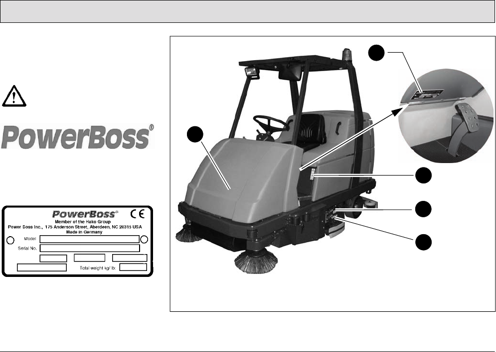
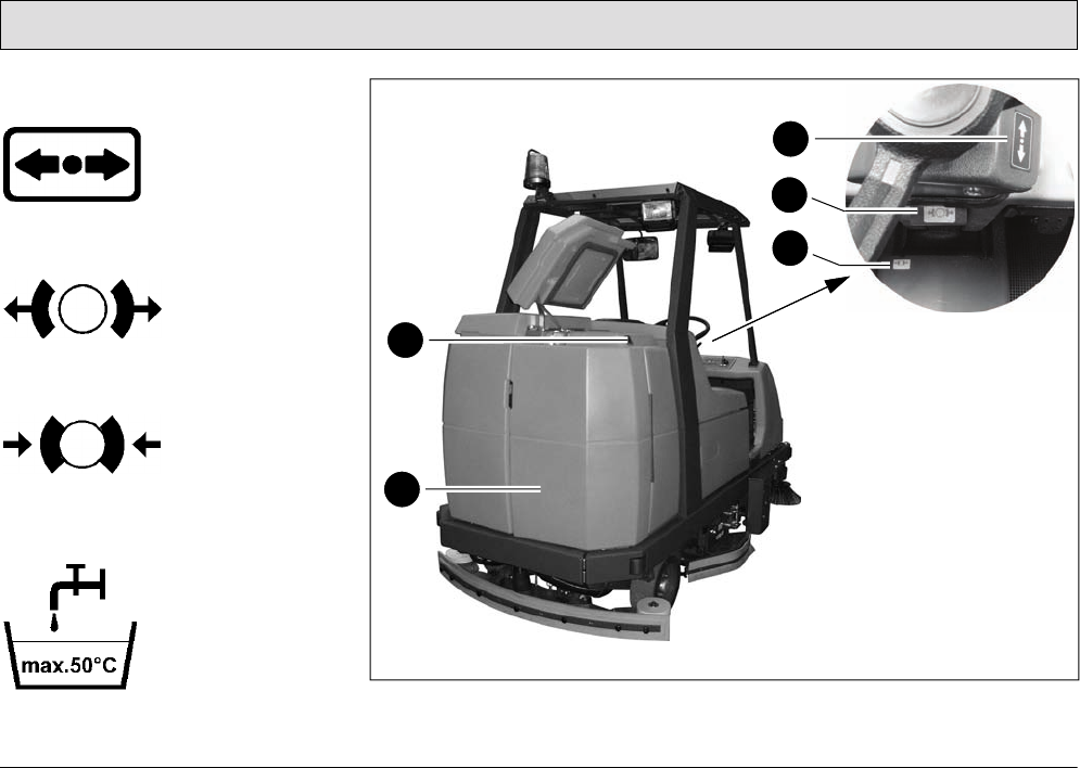
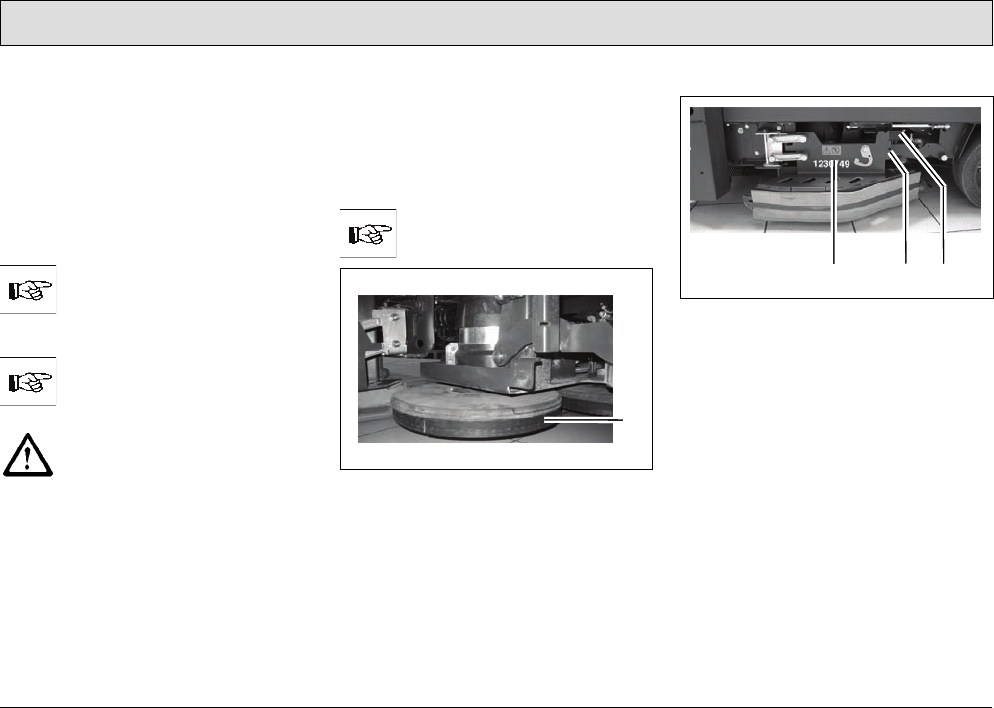
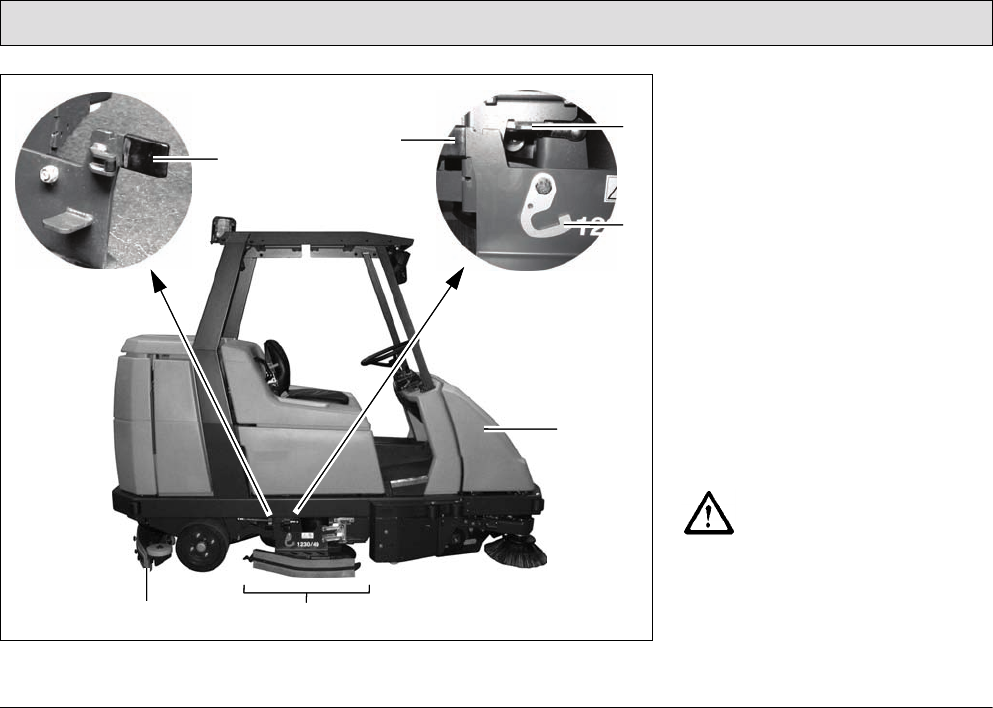
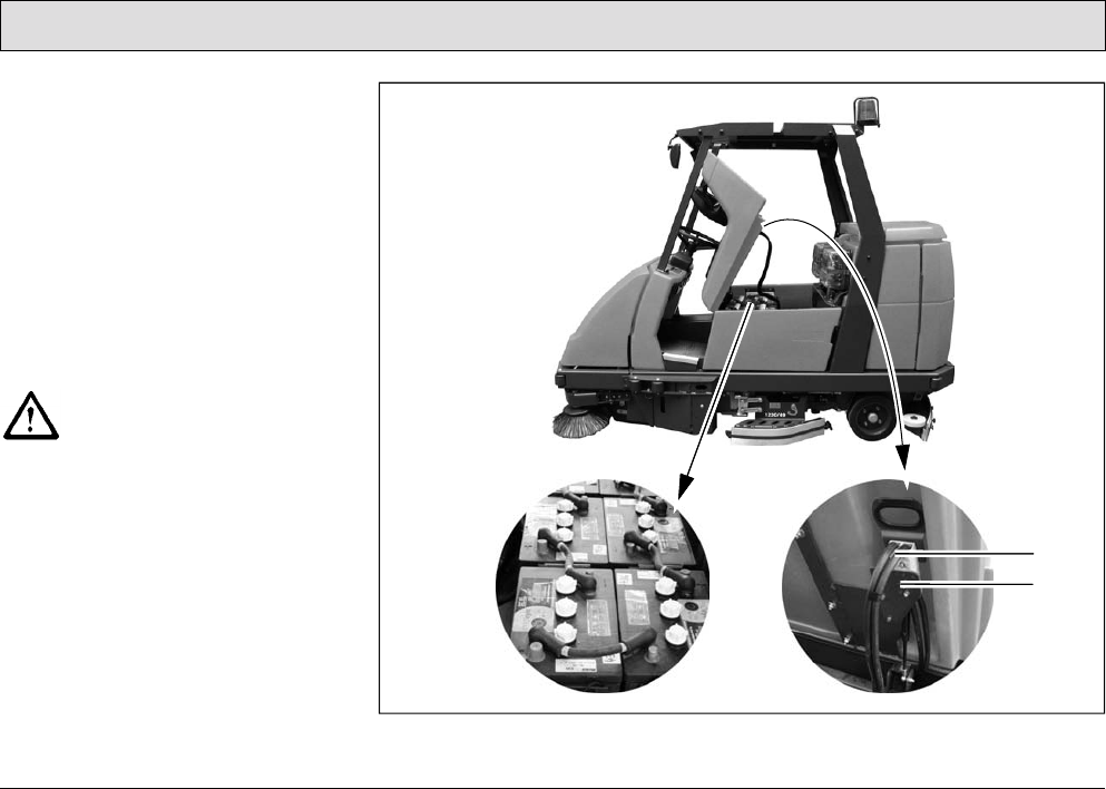
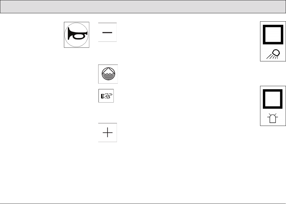
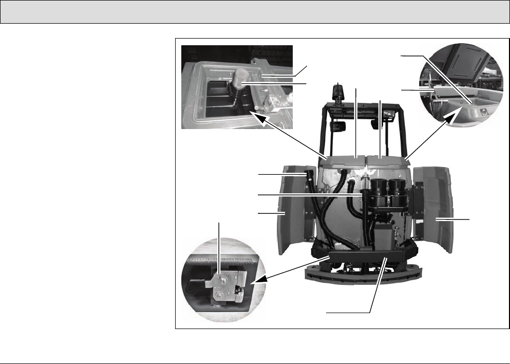
Company logo (Fig. 1/1)
(Fig. 2/1)
Rating plate (Fig. 1/2)
The rating plate is in the driver's cab, at
the bottom on the flap of the left-hand
electrical compartment.
Fig. 1
1
3
2
4
5
15
Safety Information
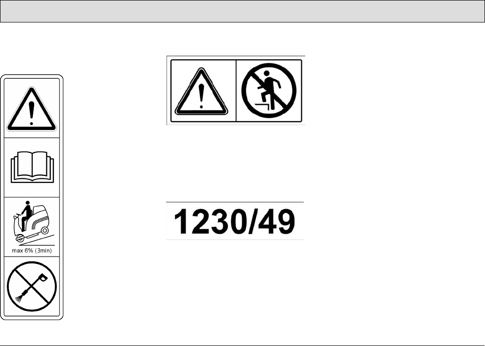
Read the operating manual, gradient
driving limits and never clean with a
high-pressure washer (Fig. 1/3)
No standing on the deflectors
(Fig. 1/4)
Working width (Fig. 1/5)
The working width of the machine is
specified in millimeters and in inches on
the deflectors to the left and right: The
vehicle has a working width of 1230 mm
or 49 in.
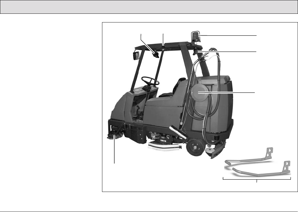
17
Safety Information
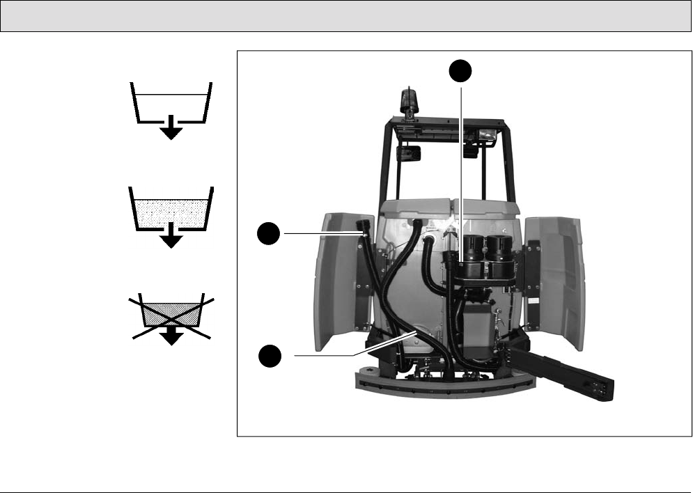
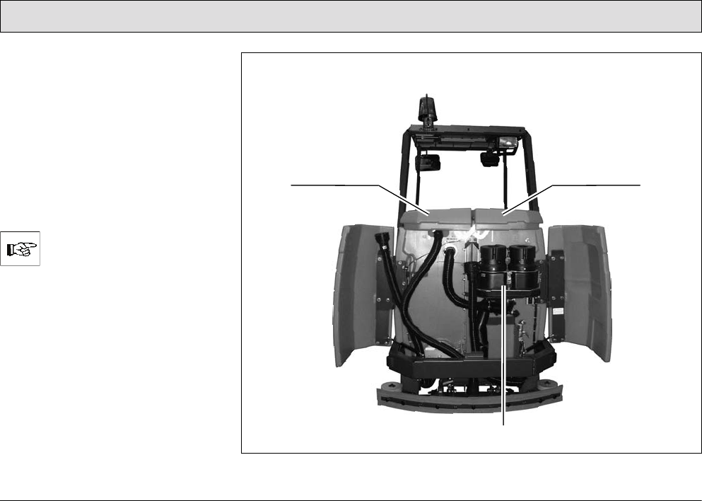
Fresh water drainage
(Fig. 3/10)
The fresh water is
drained via the hose
which hangs to the
left of this label.
Waste water
drainage
(Fig. 3/11)
The waste water is
drained via the hose
which hangs to the
right of this label.
No waste water
drainage
(Fig. 3/12)
The flap serves
exclusively
for cleaning
and maintenance
of the recovery tank.
Fig. 3
11
9
10
12
18
Starting Up
2 Starting Up
Pay attention to persons in the
vicinity of the vehicle when
completing any work.
2.1 Instruction
Operators must receive instruction
before the vehicle is put into service.
Only technicians from your local
authorized PowerBoss dealer are
allowed to provide initial instruction on
the vehicle. The manufacturing plant
will notify the dealer immediately after
delivering the vehicle and the dealer will
contact you to arrange a date.
2.2 Initial battery charge
An initial battery charge must be
performed on the batteries in order for
them to provide an optimum
performance and service life. A battery
charger is available which is specially
adapted to the batteries.
The seat console must be tipped up
during the charging process. To do this,
take hold of the seat console at the
handle and pivot it forwards to open it.
The seat console must be
pivoted open during the battery
charging process to prevent
the development of explosive
oxyhydrogen!
Only use the original charger!
Pay attention that the
insulation is not initially
damaged and not damaged
during the charging process.
The cable must not rub against
anything. Do not use the
charger if the insulation is
damaged.
Do not inhale battery gases.
Only use batteries and
chargers recommended by us.
The full terms of warranty can
only be accepted when these
units are used.
Before starting the vehicle up
for the first time, the batteries
to be used must be fully
charged, properly, by
implementing the initial battery
charge routine. PowerBoss
assumes no liability for
damage to the battery caused
by a fault when the battery is
charged for the first time.
Please pay attention to the operating
manual provided with the charging unit
as well as the manual from the battery
manufacturer. Powering up the
batteries is described in such detail in
the manufacturer's documents, further
information on the subject is considered
unnecessary for this manual.
19
Starting Up
2.3 Prior to starting up for the
first time
The following work must be completed
before starting the vehicle up for the
first time:
2.3.1 Installing brushes and pads
The machine must have three brushes
or three pads fitted.
Before starting to use the
vehicle for the first time, ensure
that appropriate brushes or
pads have been installed.
The brush head has to be in
lifted position when changing
the brushes.
Switch off the scrubbing unit,
set the key switch to position 0
and remove the key.
Selecting brushes
The scrubber-drier must be equipped
with the brushes and pads from the
accessories program according to the
degree of soiling and characteristics of
the floor.
Refer to Section 4 for the
brushes available.
Fig. 4
At the factory, a water retaining ring
(Fig. 4/1) is fitted to the brushes which
reduces water consumption
considerably during scrubbing.
Opening and closing the deflector
Fig. 5
1 Deflector
2Deflector lock
3 Grip
Open the deflector (Fig. 5/1) before
assembling or disassembling brushes
and pads:
1. Take hold of the deflector (Fig. 5/1)
by the grip (Fig. 5/3).
2. Raise the deflector (Fig. 5/1) and
pivot outwards to the front.
3. Lower the deflector (Fig. 5/1)
(service position).
The deflector is closed in the opposite
sequence.
1
123
20
Starting Up
Assembly sequence
Assemble the middle brush or pad first
and then mount the outer
brushes/pads.
Disassembly sequence
The outer left brush or pad must be
disassembled before the middle brush
or pad can be disassembled.
Disassemble the middle brush
or pad preferably from the left-
hand side of the vehicle
because the guiding aid for the
assembly tools is located here.
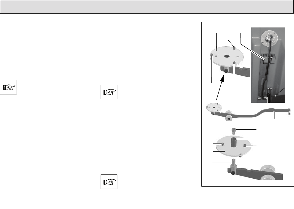
Assembly tool
To simplify assembly and disassembly
of the middle brush or pad in particular,
an assembly tool (Fig. 6/4) is provided
which is kept in a corresponding holder
(Fig. 6/3) under the seat console which
can be opened out.
Both sides of the plate (Fig. 6/1) of the
assembly tool (Fig. 6/4) can be used:
• To assemble brushes, the flat side of
the plate (Fig. 6/1) (without centering
device (Fig. 6/6)) must point
upwards.
• To assemble pads, the side of the
plate (Fig. 6/1) with the centering
device (Fig. 6/6) must point
upwards.
There are pins (Fig. 6/2) on
both sides of the plate
(Fig. 6/1) which serve to center
the brush or pad on the
assembly tool.
Turn the plate:
1. Remove the screw (Fig. 6/5).
2. Remove the plate (Fig. 6/1) from the
dowel (Fig. 6/7).
3. Turn the plate (Fig. 6/1) over.
4. Fit the plate (Fig. 6/1) upside down
on the dowel (Fig. 6/7).
5. Insert and tighten the screw
(Fig. 6/5).
The assembly tool (Fig. 6/4)
can be used to assemble and
disassemble all the brushes or
pads. Fig. 6
3
6
7
1
4
5
2
2
2
2
2
1
21
Starting Up
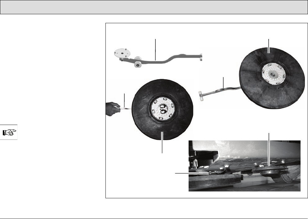
Assembling the middle brush or
middle pad
1. Open the deflector (Fig. 5/1), refer to
paragraph ”Opening and closing the
deflector”.
2. If necessary, remove the brushes or
pads already installed, refer to
paragraph ”Disassembling the outer
brushes / pads” and paragraph
”Disassembling the middle brush or
middle pad”.
3. Position the middle brush (Fig. 7/2)
or middle pad (Fig. 7/5) as illustrated
in Fig. 7 on the assembly tool
(Fig. 7/1).
The correct side of the plate of
the assembly tool must point
upwards, refer to paragraph
”Assembly tool”.
4. Take hold of the assembly tool
(Fig. 7/1) at the narrow end and slide
the brush (Fig. 7/2) or pad (Fig. 7/5)
under the middle brush catch
(Fig. 7/4).
Fig. 7
5
12
4
1
1
3
22
Starting Up
5. Force the narrow end of the
assembly tool (Fig. 7/1) downwards.
As a result of the levering effect, the
brush (Fig. 7/2) or pad (Fig. 7/5) is
pressed into the brush catch and
audibly latches in place.
6. In order to control whether all the
hooks are in place, turn the brush or
pad installed once.
7. Continue by assembling the outer
brushes, refer to paragraph
”Assembling the outer
brushes / pads”.
8. Close the deflector, refer to
paragraph ”Opening and closing the
deflector”. The deflector (Fig. 5/1) is
now in its working position.
Assembling the outer
brushes / pads
1. Open the deflector (Fig. 5/1), refer to
paragraph ”Opening and closing the
deflector”.
2. Slide the brush (Fig. 7/2) or pad
(Fig. 7/5) under the brush head in
accordance with Fig. 8.
3. Raise the brush (Fig. 7/2) or pad
(Fig. 7/5) and turn it slightly until the
toothing meshes.
4. Pull the brush (Fig. 7/2) or pad
(Fig. 7/5) up until all six hooks latch
in the catches.
Fig. 8
5. In order to control whether all the
hooks are in place, turn the brush or
pad installed once.
6. Close the deflector, refer to
paragraph ”Opening and closing the
deflector”. The deflector (Fig. 5/1) is
now in its working position.
You can also use the assembly
tool as an aid to complete
steps 2 to 4, refer to the
corresponding steps 3 to 5 in
paragraph ”Assembling the
middle brush or middle pad”.
When completing Step 5, pay
attention that you must
simultaneously use your free
hand to push down on the
brush head! Exerting
counterpressure is the only
way to ensure that the brush or
pad engages properly!
Disassembling the outer
brushes / pads
1. Open the deflector (Fig. 5/1), refer to
paragraph ”Opening and closing the
deflector”.
2. Pull the brush (Fig. 7/2) or pad
(Fig. 7/5) from the brush head. Or:
3. Slide the narrow side of the
assembly tool between the
brush/pad and brush head and press
the wide end of the assembly tool
downwards. As a result of the
levering effect, the brushes / pads
are released from the brush head
(Fig. 7/3).
1
23
Starting Up
Disassembling the middle brush or
middle pad
To simplify disassembling the
middle brush, a guiding aid is
provided on the left-hand side.
1. Open the left-hand deflector, refer to
paragraph ”Opening and closing the
deflector”.
2. Disassemble the outer left brush or
pad, refer to paragraph
”Disassembling the outer
brushes / pads”.
3. Insert the narrow side of the
assembly tool (Fig. 9/1) in the
guiding aid (Fig. 9/2).
4. Slide the assembly tool (Fig. 9/1) as
far as possible to the rear.
5. Force the broad end of the assembly
tool with the plate (Fig. 6/1)
downwards. As a result of the
levering effect, the brush or pad
(Fig. 9/3) is released from the brush
head.
6. Draw the assembly tool (Fig. 9/1)
back and remove from the guiding
aid (Fig. 9/2).
Fig. 9
1
2
3
24
Starting Up
2.3.2 Installing and adjusting
the squeegee
Fig. 10
Installing the squeegee
1. Switch on the key switch.
2. Lower the holding attachment of the
squeegee: Press the button for the
squeegee and suction turbine so that
the green control lamp lights up.
3. Switch off the key switch and remove
the key.
4. Open the rear doors.
5. Slide the squeegee from the rear
under the lowered holding
attachment and fix the squeegee to it
with the four wing nuts (Fig. 10/1).
6. Attach the suction hose to the
connection nozzle (Fig. 10/2) of the
squeegee.
7. Insert the key in the key switch and
turn the key switch on.
8. The squeegee is raised
automatically.
9. Close the rear doors.
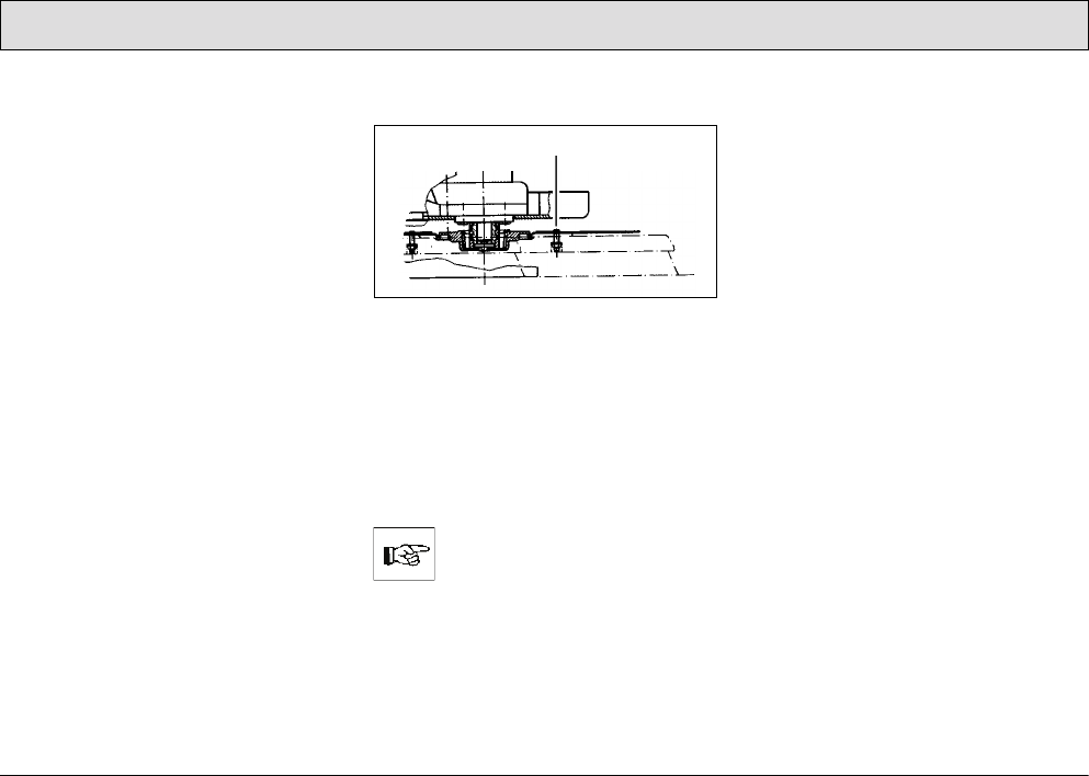
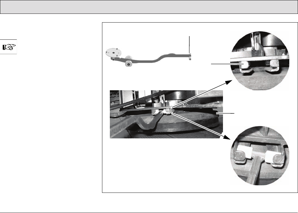
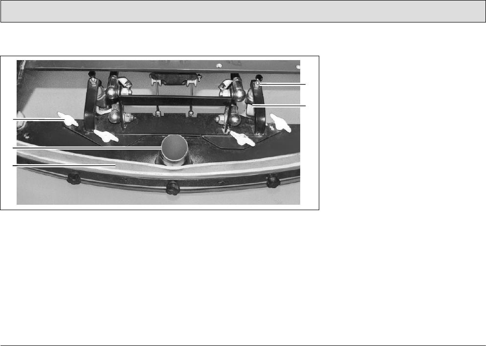
Adjusting the squeegee
The squeegee must be set up on a level
floor according to the conditions in
which it is to be used. The squeegee
must stand vertically on the floor
(adjusted at the factory). The sealing
strip (Fig. 10/3) should bend slightly to
the rear when the vehicle is in
operation. Support rollers (Fig. 10/5)
limit its movement toward the floor.
These support rollers must be adjusted
in order to raise the contact surface of
the squeegee:
• Loosen the counternuts (Fig. 10/4)
and raise the support rollers on the
left and right evenly (turn screw
counterclockwise and lock again).
The sealing strip now bends a little
more towards the rear. An
adjustment of the support rollers is also
necessary when the edge of the sealing
strip is worn.
1
2
3
4
5
25
Starting Up
2.3.3 Adjusting the driver's seat
The driver's seat (Fig. 11-13) must be
adjusted so that the driver is seated
comfortably and can reach all the
operating elements with ease.
The vehicle is equipped with a
seat contact switch. The
vehicle can only be operated
when the operating person is
seated on the seat.
The scrubber-drier is equipped with a
driver's seat which can be adjusted as
follows:
• according to the driver's weight,
• according to the angle of the seat
backrest,
• according to the longitudinal
direction (forward and back).
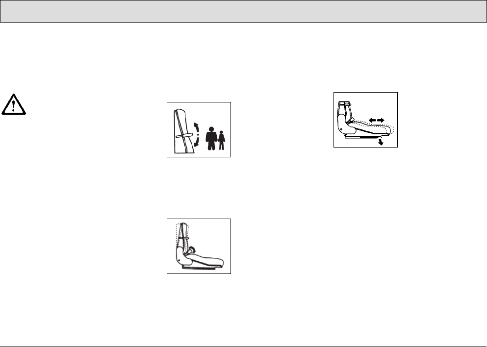
Adjusting to the driver's weight
Adjust the lever at the top right of the
backrest:
• lighter driver, pivot the lever upwards
• heavier driver, pivot the lever
downwards
Fig. 11
Adjusting the angle of the seat
backrest
Turn the knob on the bottom right of the
backrest accordingly.
Fig. 12
Adjusting longitudinally
1. Force the lever on the right of the
seat outwards slightly.
2. Slide the seat forward or back in
steps of 0.6 in.
Fig. 13
26
Starting Up
2.4 Before starting up daily
Carry out the following checks before
starting the vehicle up for its daily
operation (also refer to Section 5.3.1):
1. Check the recovery tank, empty it if
necessary. Clean it as necessary.
Refer to Sections 5.6.1 and 5.6.2.
2. Fill the fresh water tank and add a
cleaning agent in accordance with
the manufacturer's mixing directives.
Refer to Section 3.1.5 and Section
5.5.1.
Only use cleaning agents (non-
foaming) suitable for the
vehicle's vendor. We
recommend using our clean
and care products which are
specially balanced for the
vehicles.
3. Check the battery charge and
recharge as necessary; refer to
Section 5.4.1.
Before starting the vehicle for
its first working operation, carry
out an initial battery charging
routine; refer to Section 2.2.
4. Check the parking space for signs of
leaks. Hoses, lines and tanks must
show no signs of leaks or damage. If
necessary, clear up any defects
before putting the vehicle into
operation.
27
Operation
3 Operation
Operating personnel must
read the operating manual
through carefully. Operating
personnel should complete
their initial test drive on a
sufficiently large piece of open
space until they are familiar
with the individual operating
elements and the respective
functions.
3.1 Method of operation
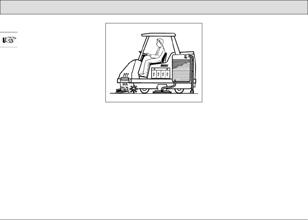
The Admiral 48D is a scrubber-drier for
wet cleaning hard floors (refer to
Fig. 14). It cleans floors by means of
intensive scrubbing with the aid of a
water and cleaning agent solution. The
squeegee at the rear of the vehicle
vacuums up the waste water into the
recovery tank in the same working
process.
By using the pre-sweep/vacuum unit,
the vehicle can also be operated
according to the tandem principle for
the advanced sweeping and dry
cleaning of hard floors: the dirt is swept
up dust-free using two side brushes and
a cylindrical brush.
Fig. 14
The scrubber-drier is a ride-on machine
designed for the economic cleaning of
large floor areas in buildings. A seat
contact ensures that the vehicle can
only be operated when an operator is
seated on the driver's seat.
The most important vehicle elements
are described below:
3.1.1 Pre-sweep/vacuum unit
(Fig. 15/4)
The pre-sweep/vacuum unit sweeps
and vacuums up dirt in dry areas in front
of the scrubbing unit without swirling up
dust. In this case, the two side brushes
sweep the dirt directly in the track of the
cylindrical brush. The side brushes
sweep up the dirt from corners and
edges so that it is not necessary to drive
too close to shelves, walls, machines,
etc. and a driving clearance to allow
steering can easily be maintained. The
cylindrical brush then sweeps the dirt
forwards into the dirt hopper. The fine
dust swirled up by the cylindrical brush
is drawn up by the extractor fan and fed
to the filter element. Only clean air is
blown from the machine. The
Admiral 48D complies with dust
category U (BIA). The pre-sweeping
and vacuuming system and the filters
are easily accessible for maintenance
tasks.
28
Operation
Fig. 15
3.1.2 Scrubbing unit
(Fig. 15/5)
Three disk brushes, which can be
changed without the need of tools,
ensure a high cleaning performance.
They are each driven by a brush motor.
The brush pressure can be adjusted
electrically according to the floor and
accumulation of dirt.
When the brushes are raised, the water
supply and brush rotation are stopped
automatically. The deflection bars to the
left and right of the disk brushes can be
raised, if necessary. This ensures the
cleaning solution is not forced to the
center of the vehicle and, as a result,
can soak the dirt. This is necessary for
basic cleaning (wet scrubbing only), for
example. Hook in the deflectors, refer to
paragraph ”Scrubbing unit”.
In the case of all cleaning work
involving immediate
vacuuming, the deflectors
must be unhooked so that the
deflectors make contact with
the floor.
2
1
6
3
1
4
5

29
Operation
Deflectors
(Fig. 15/5)
To the right and left of the disk brushes,
near the floor, are two deflectors which,
when in their working position, prevent
water splashing to the sides and guide
the waste water to the center of the
vehicle so that it can be vacuumed up
better.
The deflectors can be raised, if
necessary. This is the case for basic
cleaning, for example, where the floor
only needs to be scrubbed when wet
and the solution is not vacuumed up but
allowed to soak in instead. To raise the
deflector, take hold of the grip
(Fig. 15/1), raise it and hook the locking
hooks (Fig. 15/3) in the recesses in the
angle (Fig. 15/2) above it. Proceed in
the same way on the other side of the
side of the vehicle.
3.1.3 Squeegee
(Fig. 15/6)
The squeegee, which projects at the
sides, is fixed to the scrubber-drier so
that it can pivot and swing. This enables
it to evade obstacles in the current track
and pivot back. Its strong suction
capacity ensures the waste water is
vacuumed up fully even on uneven
floors and in bends, leaving the floor dry
enough to be walked on. The squeegee
must be checked prior to starting work,
when disposing of waste water and/or
filling the fresh water tank and cleared
of any foreign bodies which have been
vacuumed up.
Check that the sealing strips are in
perfect condition. The rollers serve to
support the squeegee to prevent
excessive bending of the sealing strips.
The squeegee is automatically raised
when reversing.
3.1.4 Suction turbines (suction)
(Fig. 16/3)
The two suction turbines are located on
the rear panel of the fresh water tank
and can be accessed after opening the
rear doors. The suction turbines are
switched on and off automatically when
lowering and raising the squeegee,
respectively. A float switch in the
recovery tank switches the suction
turbine off automatically on reaching
the maximum fill height.
30
Operation
3.1.5 Fresh water tank
(Fig. 16/2)
The fresh water tank is located behind
the driver's seat on the right-hand side.
The fresh water tank is a tank
partitioned by a membrane panel and
has a volume of approx. 81.9 gal. Open
up the red tank cap and secure it to fill
the tank. Fill water, max. 122 °F, and
add the cleaning agent in accordance
with the manufacturer's instructions.
Lower the cap again to close it.
Only use cleaning agents (non-
foaming) suitable for the
vehicle's vendor.
We recommend using our clean and
care products which are specially
balanced for the scrubber drier.
Observe the correct dosage of the
cleaning agent. The correct dosage
helps to reduce costs and protect the
environment.
Fig. 16
3
12

31
Operation
The development of excessive foam
impairs the vehicle's function. It
indicates overdosage of the cleaning
agent; components of the cleaning
agent which are fed back to the waste
water cause foaming. Information on
dosage is provided on the cleaning
agent container. Use the
manufacturer's information as an initial
guideline. Practical experience will
ensure that you quickly find out which is
the right cleaning agent and the
optimum dosage to suit your needs.
The fresh water supply to the brushes is
automatically opened when the
scrubbing program is activated. If
necessary, the feed can be stopped
manually by means of the ball cock.
Operating times with one tankful:
• at 0.5 gal/min approx. 155 minutes
• at 1.1 gal/min approx. 77 minutes
• at 1.8 gal/min approx. 44 minutes
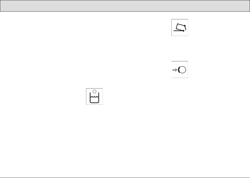
3.1.6 Recovery tank
(Fig. 16/1)
The recovery tank is located behind the
driver's seat on the left-hand side. The
recovery tank is a tank partitioned by a
membrane panel and has a volume of
approx. 81.9 gal. The waste water is fed
to the recovery tank via the squeegee
by means of a vacuum. A float switch at
the top of the recovery tank switches
the suction turbine off automatically as
soon as the maximum tank fill level is
reached. In this case, the control lamp
(Fig. 19/2) on the left operating panel
lights up. An acoustic signal is also
issued. A spray/vacuum tool (refer to
Section 4), which can be connected to
the vehicle, is optionally available with
which to clean and vacuum up water
from areas difficult to access.

32
Operation
3.1.7 Traction drive
The traction drive is provided by a drive
motor on the steerable front wheel. The
driving speed can be continuously
regulated via the accelerator by means
of the electronic drive control (pulse
contact control). The axle gear is a gear
train which runs in an oil bath.
In the case of faults involving
the traction drive, stop the
vehicle immediately and
remove the key from the key
switch!
3.1.8 Brakes
The scrubber-drier is equipped with a
service brake and a parking brake.
The service brake relates to a drum
brake which acts hydraulically on the
rear wheels. It is actuated by a foot
pedal. The parking brake is actuated
mechanically via brake cables. It is
applied by means of the foot pedal to
the left of the steering column and
released using the safety catch in the
steering column.
33
Operation
3.1.9 Batteries and charger
The scrubber-drier is powered by a
traction battery (36 Volt / 395 Ah5),
6 monobloc batteries each producing
6 Volt. They are fit in a battery tray.
To ensure protection against deep
discharge, the scrubber drier is
equipped with a deep discharge signal
transducer (Battery Management
System (BMS)). It is integrated in the
electronic system and set up at the
factory for GiS batteries (service
indicator: No. 5).
If other batteries are used, the
deep discharge signal
transducer must be adjusted.
This adjustment work should
only be performed at an
authorized PowerBoss service
center.
The battery is provided with a
connection cable with battery plug
(Fig. 17/1). When the battery plug is
plugged into the vehicle socket
(Fig. 17/2), the vehicle is ready to
operate.
Fig. 17
1
2

34
Operation
In order to charge the battery, the
battery plug must be plugged into an
adapter and the adapter connected to
the charger.
The vehicle includes an adapter
comprised of two plugs connected by a
11.8 in long piece of cable.
The adapter belongs to the
scope of delivery of the
vehicle.
The battery charger is not
contained in the scope of
delivery of the vehicle.
Only use an appropriate
charger!
Pay attention to the safety information
enclosed with each battery.
35
Operation
3.1.10 Options
1 Working lights
2 Cab safety roof
3 Flashing beacon
4 Spray/Vacuum tool
5 Side brush collision protection
6 Side collision protection
(not assembled in the illustration)
Fig. 18
13
4
2
5
6
1
36
Operation
The basic vehicle can be supplemented
by further components. The order and
spare parts numbers of these
components are in brackets.
Please refer to our spare parts
catalogue in Internet under
www.powerboss.com for
information on accessories
such as brushes, pads, drive
plates with centerlock etc.
•Working lights
(Fig. 18/1) (7584.02)
Area of use: To enable use of the
vehicle even in badly lit areas.
•Cab safety roof
(Fig. 18/2) (7582)
Area of use: To protect the driver,
e.g. from parts which could fall from
high rack warehouses. Including
rear-view mirror.
Pay attention that assembly of
a cab safety roof is made
compulsory when the vehicle is
operated in such risk areas.
•Flashing beacon
(Fig. 18/3)
(7585.02 Assembly on cab safety
roof)
(7585.10 Assembly on pole / without
cab safety roof)
Area of use: To improve awareness
of the vehicle when in use.
•Spray/Vacuum tool
(Fig. 18/4)
Area of use: Areas which are difficult
to access can be cleaned manually
with a spraying and vacuuming tool.
A holder can be installed on the left-
hand side of the vehicle to fix the
spray/vacuum tool. Two holes are
already drilled in the left-hand side of
the vehicle for this. The following
belong to the spray/vacuum tool:
-Floor scrubbing tool (7009)
-Suction and spraying hose
(7766)
-Tool holder and attachment
parts (7311.10)
The corresponding buttons are
provided on the left operating panel
with which to operate the
spray/vacuum tool:
- Vacuuming tool on/off switch:
Press the button to switch the fresh
water supply on and off
(Fig. 21/14).
- Press the reduce fresh water
quantity button (Fig. 21/13) or
increase fresh water quantity
button (Fig. 21/15) to set the
required water quantity, also refer
to Section "Keypad to control the

37
Operation
fresh water supply“ (Fig. 21/12).
- Press the squeegee and suction
turbine button (Fig. 21/10) to switch
the suction turbine on or off.
When the spray/vacuum tool is
in operation, the scrubber-
drier's parking brake must be
applied.
The spray/vacuum tool only
functions when nobody is
sitting on the driver's seat and
the parking brake is applied.
•Hand-held vacuum cleaner
(Fig. 18/4)
Area of use: For vacuuming up water
manually in areas which are difficult
to access.
The hand-held vacuum cleaner can
be fixed to the tool holder (refer to
spray-vacuum tool).
The hand-held vacuum cleaner
contains:
-Adapter to connect the following
tools (7893)
-Suction hose (flexible plastic
extension hose), length: 9.8 ft
(7880)
-Suction pipe (for connection to the
plastic extension hose), length:
4.3 ft (7881)
-Suction nozzle with rubber lips
(7883)
Operation of the hand-held vacuum
cleaner: refer to Spray/Vacuum
Tool, page 36.
•Side brush collision protection
(Fig. 18/5)
(7581.50)
The collision protection for the two
side brushes on the pre-
sweep/vacuum unit consists of two
angled steel bars which can be
assembled at the front left and front
right of the pre-sweep/vacuum unit
(Fig. 15/4) and protect the scrubber-
drier from damage caused by
collisions.
•Side collision protection
(Fig. 18/6)
(7680.30)
The side collision protection consists
of two steel bars which can be
assembled on the right and left-hand
sides of the vehicle at the height of
the disk brushes and deflectors to
protect the scrubber drier from
damage cause by collisions. The
side collision protection can be
disassembled quickly without the
need of any tools.
39
Operation
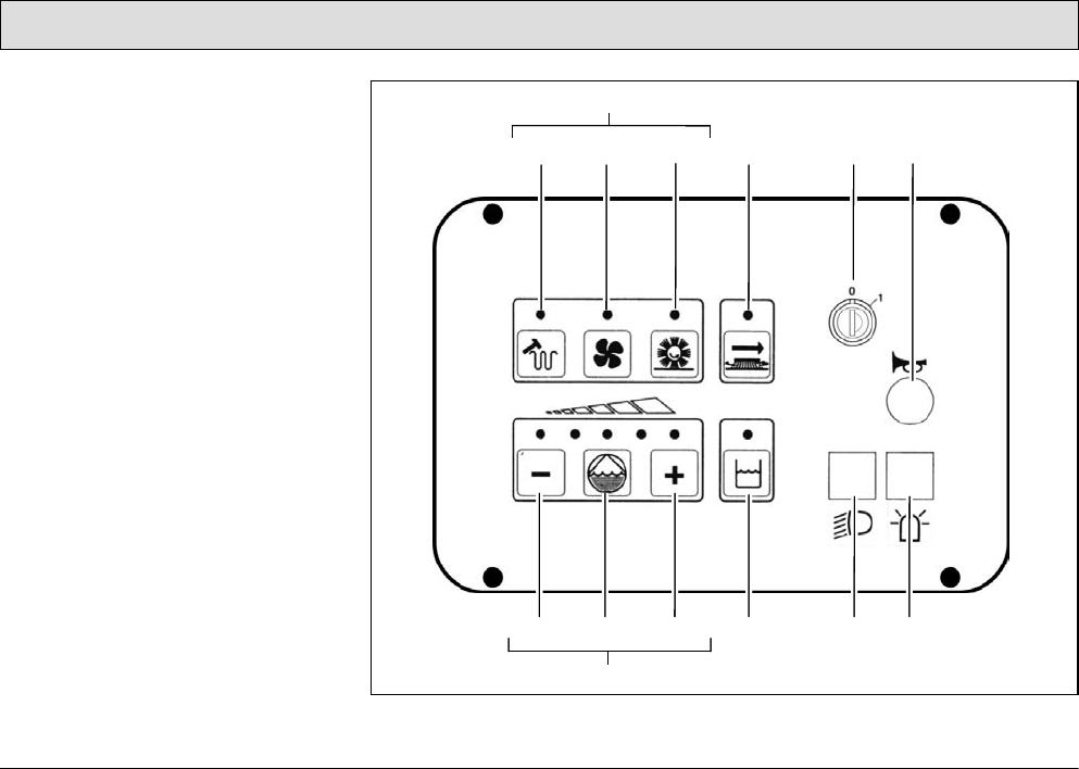
3.2 Operating and indicator
elements
3.2.1 Operating elements
in the driver's cab
1 Steering wheel
2 Left-hand operating panel
3 Safety catch
(to release the parking brake)
4 Parking brake
5 Direction switch
(forwards/reverse)
6 Right-hand operating panel
7 Service brake
8 Accelerator pedal for speed control
of forward and reverse drive
Fig. 20
2
3
48
7
6
5
1

40
Operation
Steering wheel
(Fig. 20/1)
• The scrubber-drier is steered by the
steering wheel.
Left-hand operating panel
(Fig. 20/2)
• This operating panel contains all the
buttons for the electronically
controlled, standard cleaning
programs.
• Individual functions can be added or
removed from the cleaning process,
as necessary.
• All the buttons are provided with
clearly descriptive labels.
• The green control lamps in the
operating buttons serve as function
indicators.
• The significance and functioning
method of the individual buttons on
this operating panel is described in
paragraph 3.2.2.
Safety catch
(Fig. 20/3)
• The safety catch serves to release
the parking brake when applied.
• Operating sequence to release
brake:
- Tread on the pedal slightly.
- Press the catch down.
- Release the pedal.
Parking brake
(Fig. 20/4)
• The pedal to the left of the steering
column serves to apply the parking
brake to the rear wheels.
• When the parking brake is applied,
the corresponding control lamp on
the operating panel (Fig. 21/4) lights
up red.
• If the driving direction switch is
actuated while the parking brake is
applied, an intermittent "beep" is
issued.
Before getting out of the
vehicle apply the parking
brake, set the driving direction
switch (Fig. 20/5) to its neutral
position and switch the key
switch to off.
Drive direction switch
(forwards/reverse)
(Fig. 20/5)
• It serves to select the driving
direction:
- Forward: control switch forward
- Reverse: control switch back
- Stop: control switch in center
(neutral position)
• To change the driving direction, stop
the vehicle by applying the service
brake, select the new direction and
accelerate again.

41
Operation
Right-hand operating panel
(Fig. 20/6)
• This operating panel contains the
key switch to switch the vehicle on
and off, the horn and a range of
switches to operate the optional
equipment, also refer to
paragraph 3.2.3.
Service brake
(Fig. 20/7)
• In order to slow the vehicle down and
bring the scrubber-drier to a stop,
tread on the foot pedal to the left of
the accelerator (as with a normal
vehicle) to actuate the hydraulic
service brake.
Accelerator to drive forwards and
backwards
(Fig. 20/8)
• The pedal on the right serves to
control the driving speed (as in a
normal vehicle).
• Before actuating the accelerator, use
the driving direction switch
(Fig. 20/5) to set the direction of
travel: forwards or reverse.
• Forwards or reverse (according to
the driving direction switch setting):
Press the accelerator forward and
down slowly.
• Release the pedal: The speed is
automatically reduced, slowly. The
vehicle rolls to a stop until reaching
its zero setting.
• To stop securely, apply the service
brake (Fig. 20/7).
• The speed for forward drive is
approx. 5.0 mph and for reverse
drive approx. 2.5 mph.
• The working speed when the
brushes are switched on, the
squeegee is lowered and pre-
sweep/vacuum unit is approx.
4.4 mph.
An acoustic warning signal
(buzzer) is issued should the
drive motor overload. At the
same time, the red alarm lamp
(Fig. 20/5) lights up in the left-
hand operating panel
(Fig. 21/2) and the driving
speed is reduced by
approx. 50%. In addition, an
error code appears in the
service indicator (Fig. 21/6).
42
Operation
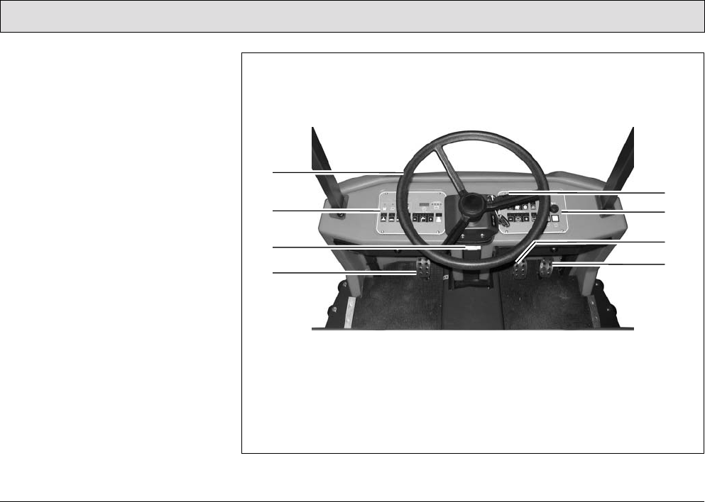
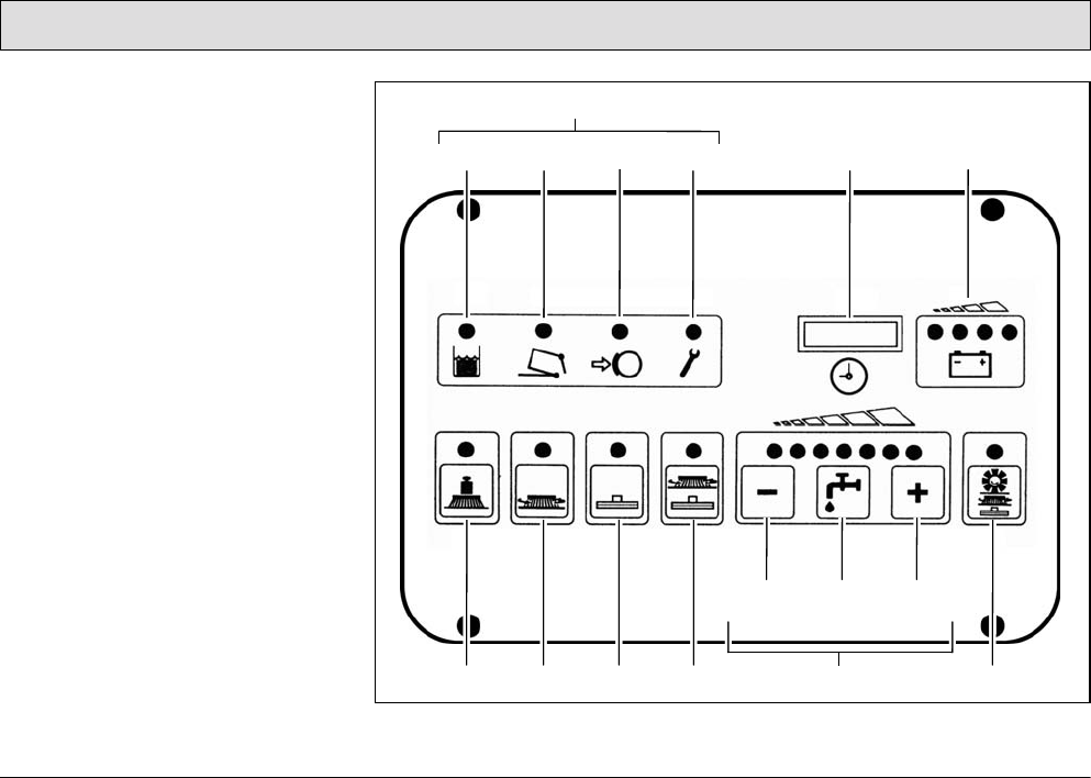
3.2.2 Left-hand operating panel
(Fig. 21)
1 Indicator field
2 Recovery tank indicator: When the
control lamp is on (yellow), the max-
imum fill level has been reached.
3 Dirt hopper and front flap indicator of
the pre-sweep/vacuum unit
4 Parking brake indicator: When the
control lamp is on (red), the brake is
applied.
5 Alarm indicator: When the control
lamp is on (red), a functional fault
has occurred.
6 Operating hour counter and service
indicator
7 Battery and charge control indicator
8 Button for brush pressure
9 Button for brush drive
10Button for squeegee and suction tur-
bine
11Button for simultaneous activation of
the scrubbing unit and vacuuming
function
12Buttons for controlling the fresh
water supply
- Continued on next page -
Fig. 21
2
1
465 7
8 9 10 11 12 16
13 14 15
3
43
Operation
- Continued -
13Button to reduce fresh water quan-
tity
14Button to switch fresh water supply
on and off
15Button to increase fresh water quan-
tity
16Button for simultaneous activation of
pre-sweep/vacuum unit, scrubbing
unit and vacuuming function
Indicator field
(Fig. 21/1) The indicator field enables
the scrubber-drier to provide feedback
on the operating status of the vehicle.
This only relates to operating states
which cannot be switched on and off via
the operating panel: recovery tank full,
dirt hopper for pre-sweep/vacuum unit
full, parking brake applied and error
message.
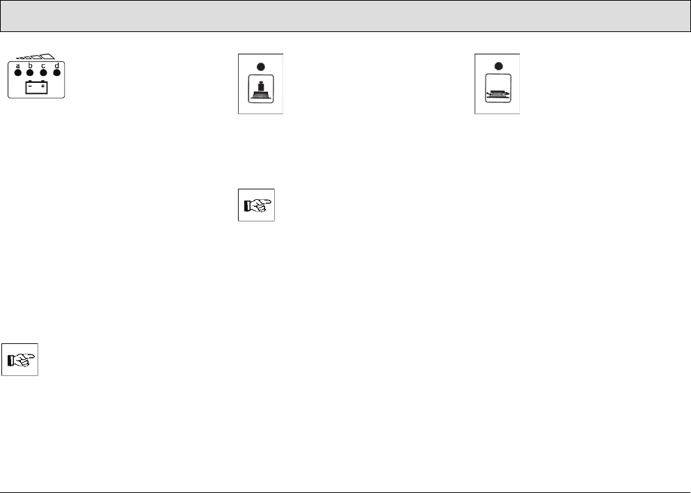
The individual buttons and functions are
described in detail below:
Indicator for recovery tank
maximum fill level
(Fig. 21/2) The yellow
control lamp lights up when
the recovery tank has
reached its maximum fill level. Also, a
"beep" signal is issued every 15
seconds. In this case, a float switch
switches the suction turbine off and the
squeegee is raised.
Dirt hopper and front flap
indicator of the pre-
sweep/vacuum unit
(Fig. 21/3) The control lamp
lights up red when the dirt hopper is not
properly inserted (engaged) or the front
flap is not properly closed.
Indicator for parking brake
applied
(Fig. 21/4) The control lamp
lights up red when the
parking brake has been
actuated via the pedal to the left of the
steering column. If the traction drive is
switched on, an acoustic signal is also
issued.

44
Operation
Indicator for function
faults
(Fig. 21/5)
The control lamp lights up
red when one of the following
faults occurs:
• Thermostatic switch of the brush
motor, drive motor or cylindrical
brush has switched off
• One of the safety fuses is defective
or an electronic fuse has been
tripped.
• Another fault has occurred.
At the same time, a four-digit code
appears in the display of the service
indicator (Fig. 21/6). This error code
infers which fault has occurred (refer to
Section 3.5.1). At the same time, the
control lamps flash and an acoustic
signal is issued.
Operating hour
counter
(Fig. 21/6) The four-digit
LED serves to display
the operating hours.
When the key in the key switch is turned
on, one and then two four-digit codes
appear in succession (for further
details, refer to page 48, Key switch
(Fig. 22/6)). The operating hours
appear after this.
The counter only operates when
consumers are switched on (e.g. drive
or brush motor, suction turbine or pre-
sweep/vacuum unit). At the same time,
a red dot flashes at the bottom right of
the display.
Service indicator
(Fig. 21/6) The four-digit
LED serves for a more
accurate determination
of function faults. If a
fault occurs during operation, a four-
digit code (error code) appears in the
service indicator display. At the same
time, the four dots of the error code
flash in the display and an acoustic
signal is issued. The control lamp
indicating functional faults lights up red.
Section 3.5.1 provides an overview of
the error codes which help you clear
functional faults yourself. Clear the fault
before starting to use the vehicle again.
If you cannot clear the fault yourself,
note down the error code and inform the
authorized PowerBoss dealer
responsible for your vehicle.
45
Operation
Battery and charge
control indicator
(Fig. 21/7) After
switching on the key
switch, all four lamps light up when the
battery is fully charged. As the battery is
discharged during operation, the three
right-hand lamps indicate the level of
discharge by going out in sequence
from right to left. When the left, red lamp
flashes, it indicates that work must
come to an end. Approximately three
minutes later, the brushes will return to
their home position. After a further three
minutes, the suction turbine is
deactivated and the squeegee is raised.
When the red lamp lights up
continuously, approximately one
minute remains until the entire vehicle
shuts down automatically.
Drive back to the charger in
good time. Take the distance
to the charger into account.
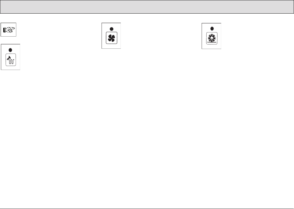
Button for brush pressure
(Fig. 21/8) This button is
used to increase the brush
pressure. This may be
necessary when the area to
be cleaned is extremely dirty.
The pressing force can be increased to
max. 205 lbs. If the function is active,
the green control lamp lights up.
Working with an increased
brush pressure also means
increased brush wear.
Therefore, only press this
button when necessary.
Button for the brush drive
(Fig. 21/9) This button
serves to switch the brushes
and fresh water supply on
and off with simultaneous,
respective lowering and
raising of the brush head. If the function
is active, the green control lamp lights
up.
46
Operation
Button for squeegee and
suction turbine
(Fig. 21/10) This button
serves to switch the suction
turbine on and off with
simultaneous lowering and
raising of the squeegee. If the function
is active, the green control lamp lights
up.
This button must also be
pressed when working with
optional tools connected to a
suction hose. Operating
personnel must not be seated
on the driver's seat in this case
(seat contact is bypassed).
Only the suction turbine is
activated at this point, the
squeegee remains raised.
Button for simultaneous
activation of the scrubbing
unit and vacuuming
function
(Fig. 21/11) After pressing
the button, the most important basic
functions for standard cleaning are
automatically activated/deactivated in
the correct sequence of use: suction
turbine, brush rotation, fresh water
supply and lowering or raising the
brushes and squeegee. When the
vehicle is ready for use in accordance
with requirements, it can be set into
operation simply and quickly by
pressing the button. When the button
has been pressed, the green control
lamp lights up.
Buttons
controlling the
fresh water
supply
(Fig. 21/12) The
fresh water consumption used during
cleaning can be regulated in seven
stages. Accordingly, there are seven
green control lamps on the keypad.
Each lamp relates to one stage. The
maximum quantity which can be used
for cleaning is 2.0 gal/min (all seven
lamps are on). The minimum quantity is
0.3 gal/min (only the left lamp is on).
The last fresh water quantity selected is
always used. When the scrubbing
program is switched on for the first time,
a fresh water quantity of approx.
0.9 gal/min is automatically set.
47
Operation
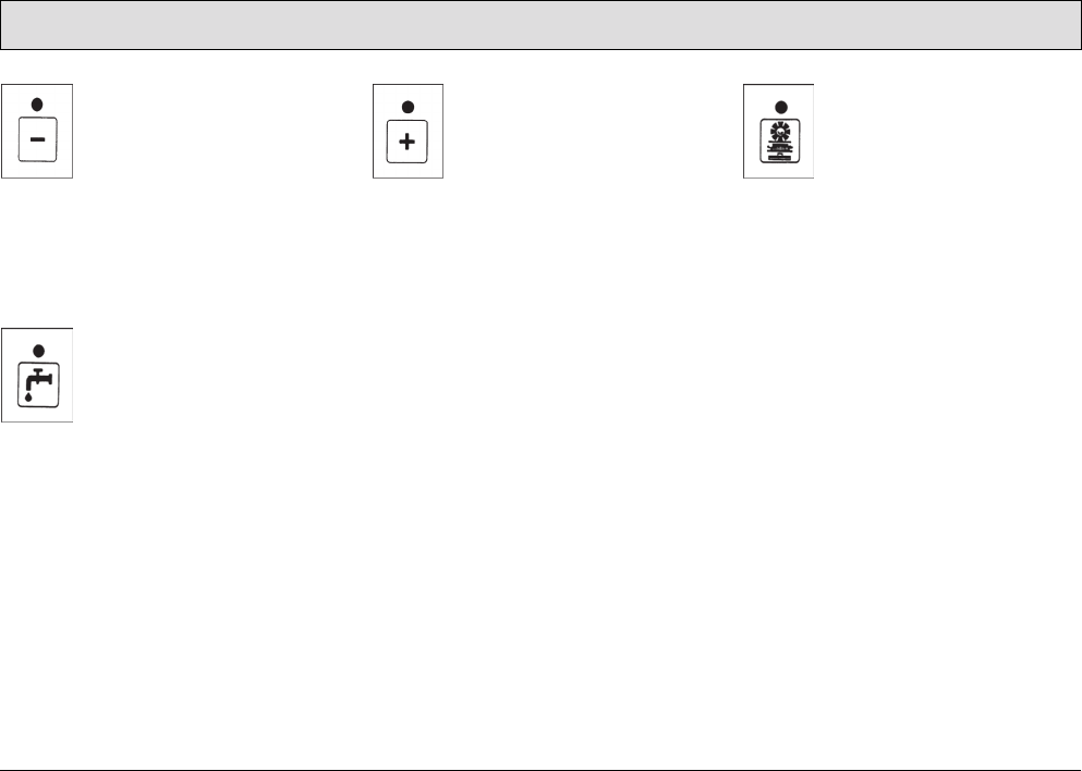
Button to reduce fresh
water quantity
(Fig. 21/13) The button
serves to reduce the fresh
water quantity supplied to
the brushes. The fresh water
quantity can be reduced in seven
stages (see above). The stage selected
remains programmed, even if the
vehicle is switched off in the meantime.
Button to switch the fresh
water supply on and off
(Fig. 21/14) This button
serves to switch the fresh
water supply on and off when
the brush head is lowered or
when using the spray/vacuum tool. The
water quantity previously set remains
unchanged.
Button to increase fresh
water quantity
(Fig. 21/15) The button
serves to increase the fresh
water quantity supplied to
the brushes. The fresh water
quantity can be increased in seven
stages (see above). The stage selected
remains programmed, even if the
vehicle is switched off in the meantime.
Button for simultaneous
activation of pre-
sweep/vacuum unit,
scrubbing unit and
vacuuming function
(Fig. 21/16) This button serves for
simultaneous activation/deactivation of
the pre-sweep/vacuum unit, brushes,
suction turbine and water supply as well
as lowering or raising the cylindrical
brush including side brush, brushes and
squeegee.
48
Operation
3.2.3 Right-hand operating panel
(Fig. 22)
1 Operating buttons for pre-
sweep/vacuum unit
2 Button for agitating device
3 Button for extractor fan
4 Button to switch pre-sweep/vacuum
unit on and off
5 Button has no function
6 Key switch
7 Horn
8 Buttons for chemical dosage option
9 Reduce quantity of cleaning agent
10Button to switch chemical dosage
option on/off
11Increase quantity of cleaning agent
12Button has no function
13Switch for working lights
14Switch for flashing beacon
Fig. 22
2
1
465 7
9 10 11 12
8
13 14
3
49
Operation
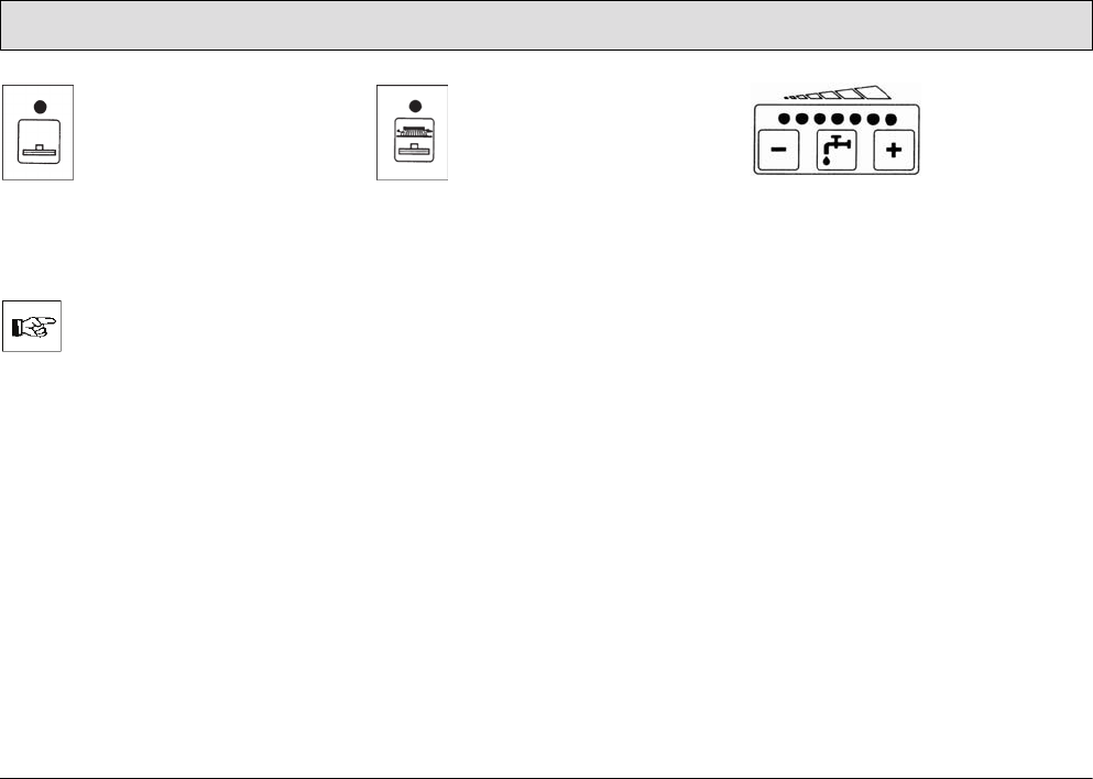
If optional accessories are not
assembled, the corresponding
buttons have no function.
Button for agitating device
(Fig. 22/2)
This button serves to switch
an agitation process on and
off, whereby the filter system
on the pre-sweep/vacuum
unit is cleared of the dust attached.
After pressing the button, an agitation
process runs for approx. 6 seconds in
intervals; press the button again to end
the process prematurely. Alternatively
to pressing the button, you can turn the
key switch to position 0 and 1 (RESET).
Button for extractor fan
(Fig. 22/3)
This button serves to switch
the extractor fan of the filter
system on and off. The filter
system is part of the pre-
sweep/vacuum unit.
Button to switch the pre-
sweep/vacuum unit on and
off
(Fig. 22/4)
This button is used to switch
the pre-sweep/vacuum unit on and off.

50
Operation
Key switch
(Fig. 22/6)
It serves to switch the
electrical installations on
and off and to secure the
vehicle against
unauthorized use.
When the key switch is switched on
(lock position 1), the following appear in
the operating hour counter display (left-
hand operating panel, refer to
"Operating hour counter" in
paragraph 3.2.2):
1Software version
Displayed for approx. 1 second.
Example:
2Error code
Indicates the error code of the last
fault which occurred and is dis-
played for approx. 2 seconds. The
display serves as information for the
service technician so that the fault
can be cleared quickly. For an over-
view of the error codes, refer to Sec-
tion 3.5.1.
Example:
When a functional fault actually
occurs, an acoustic signal is
also issued and the red control
lamp on the alarm indicator
(Fig. 21/5) lights up.
3Operating hour indicator
Continual display.
Example:
During operation, the dots flash in
the display.
4Control digits (optional)
In the case of brand new vehicles, it
is possible that after switching on
the key switch, this display also
appears:
The control digits are for internal
control purposes. The display
changes to zero operating hours
after one hour at the latest. The
scrubber-drier is ready for use while
this display appears. The alarm indi-
cator is activated.
51
Operation
Horn
(Fig. 22/7)
An acoustic warning
signal is issued on
actuating the horn knob.
Button for reducing the
quantity of cleaning agent
(Fig. 22/9)
On pressing this button, the
amount of cleaning agent added to the
fresh water is reduced.
Button to switch chemical
dosage option on/off
(Fig. 22/10)
The chemical dosage can only
be switched on when the fresh
water supply has been
switched on beforehand
(Fig. 21/14).
Button for increasing the
quantity of cleaning agent
(Fig. 22/11)
On pressing this button, the
amount of cleaning agent added to the
fresh water is increased.
Switch for working
lights
(Fig. 22/13)
This switch switches the
working lights on or off.
This occurs even without
the key switch being
turned on.
The working lights are optional
accessories.
Switch for flashing
beacon
(Fig. 22/14)
The flashing beacon is an
optional accessory.
52
Operation
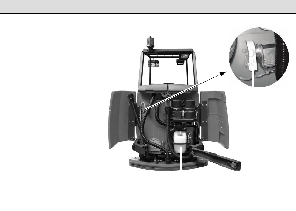
3.2.4 Operating elements on the
vehicle
1 Opening between the waste and
fresh water tank.
2 Filter sieve
3 Fresh water tank filling neck
4 Lid lock
5 Cover, recovery tank
6 Cover, fresh water tank
7 Rear door, right
8 Rear panel frame
9 Rear door, left
10Fresh water draining hose
11Waste water draining hose
12Rear panel frame lock
Fig. 23
3
4
26
5
11
10
12 9
8
7
1

53
Operation
Recovery tank
(Fig. 23/2+5)
The air intake filter (Fig. 23/2) is located
under the recovery tank lid (Fig. 23/5) at
the top of the recovery tank and is
connected to the end of the suction
pipe. It prevents coarse dirt getting into
the suction turbines and must be
checked or cleaned daily, refer to
Section 5.6.4.
Fresh water tank
(Fig. 23/3+6)
In order to fill fresh water and cleaning
agent, pivot up the lid of the fresh water
tank (Fig. 23/6) and lock it. The tank is
filled through the filling neck (Fig. 23/3),
refer to Section 5.5.1.
Lid lock
(Fig. 23/4)
The lock prevents the lid falling shut. To
lock the lid, move the bar and latch in
place. To release the lock, raise the lid
a little and pivot the lock back a little.
The lid lock functions in the same way
on the fresh water tank and recovery
tank.
Rear doors
(Fig. 23/7+9)
Open the rear doors to access the
draining hoses for waste water and
fresh water.
Waste water draining hose
(Fig. 23/11)
The draining hose for waste water
hooked is in the left-hand rear door.
Only drain off waste water through this
hose at an appropriate location, refer to
Section 5.6.1.
Fresh water draining hose
(Fig. 23/10)
The draining hose for fresh water hangs
to the left of the suction turbines. Only
drain off the fresh water through this
hose at an appropriate location, refer to
Section 5.5.2.
Rear panel frame
(Fig. 23/8+12)
In order, for example, to access the flap
to clean the recovery tank, the rear
panel frame must be opened. To do
this, pull the lock lever (Fig. 23/12) up
and open the unlocked rear panel frame
(Fig. 23/8).
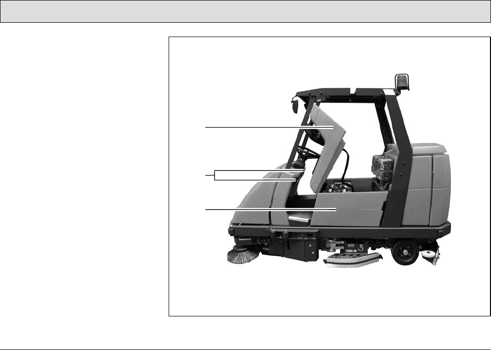
54
Operation
13Seat console
14Electrical compartments
15Side door
Fig. 24
13
14
15

55
Operation
Seat console
(Fig. 24/13)
The driver's seat is mounted on the seat
console. The seat console can be
pivoted up using the handle in order to
access the batteries and electric
system.
Electrical compartments
(Fig. 24/14)
In the driver's cab, to the left and right of
the steering column, are two electrical
compartments which must be opened
by means of a special square wrench.
The electrical compartments
are not provided in the sense
of glove compartments.
Side door
(Fig. 24/15)
The side doors are located to the left
and right of the battery. The doors must
be pivoted open in order to change the
batteries, refer to Sections 5.4.3 and
5.4.4.
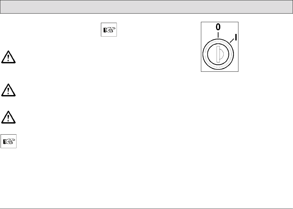
56
Operation
3.3 Operation
The scrubber-drier can be operated on
surfaces with a gradient of 6% for
maximally 3 minutes.
The climbing capacities
stipulated in this manual can
and may only be achieved with
the battery specified in the
Section „Technical Data“.
Adapt your driving style to the
local conditions (floor
characteristics, persons in the
vicinity, obstacles etc.).
When cleaning on slopes, the
traction may be impaired.
3.3.1 Switching the vehicle on
Please read Section 1 before
switching the vehicle on.
Carry out the following steps so that the
vehicle is ready to operate:
• Disconnect the battery plug from the
charger and connect it to the vehicle.
When connecting the battery
plug to the vehicle, switch the
key switch to off (lock
position 0) beforehand.
• The vehicle is equipped with a safety
shutdown via a seat contact. This
means that it is essential for
operating personnel to be seated in
the driver's seat to be able to operate
the vehicle.
• Ensure that the driving direction
switch is in its neutral setting, refer to
"Accelerator for driving forwards and
backwards" in Section 3.2.1.
Fig. 25
• Actuate the service brake with your
foot in order to prevent accidentally
accelerating the vehicle, refer to
"Service brake" in Section 3.2.1.
• Insert the key in the key switch
(Fig. 25).
• Turn the key from lock position 0 to
position 1. The vehicle is ready to
operate.

57
Operation
3.3.2 Accelerating
• Set the required driving direction
with the direction switch: set the
switch to the front to drive forward,
set the switch to the rear to reverse.
• Release the parking brake, refer to
"Safety catch" in Section 3.2.1.
• Press the accelerator down slowly
with your right foot until you reach
the required driving speed.
3.3.3 Stopping and parking
• Remove your right foot from the
accelerator to slow down. When the
foot is fully removed from the
accelerator, the vehicle rolls to a
stop.
• Now press the right foot on the
service brake pedal to stop the
vehicle and bring it to a stop.
• Turn the key in the key switch
counterclockwise to lock position 0
and remove the key.
• Press the left foot on the parking
brake pedal to park the vehicle.
Always apply the parking brake
and remove the key before
getting out of the vehicle!
3.3.4 Cleaning
If the hand-held vacuum cleaner or
spray/vacuum tool option is assembled,
there are a total of six cleaning
programs available for selection:
1. Sweeping
2. Sweeping, wet scrubbing and
vacuuming dry
3. Wet scrubbing and vacuuming dry
4. Wet scrubbing (basic cleaning)
5. Vacuuming dry
6. Working using the additional
scrubbing and vacuuming tool
(spray/vacuum tool) / vacuuming
with the suction hose (option)
The cleaning programs are activated
via the left-hand operating panel, refer
to Section 3.2.2. Press the relevant
button as soon as the scrubber-drier is
ready to operate (see above).
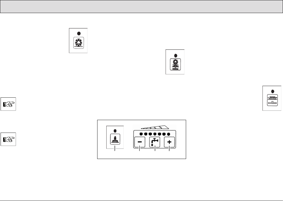
58
Operation
Sweeping
•Press the "Button for
switching the pre-
sweep/vacuum unit
on/off" (Fig. 22/4) on the
right-hand operating
panel.
Various functions can be switched on or
off with the following buttons:
• Switch extractor fan on/off
(Fig. 22/3)
If the ground is wet, always
switch the vacuum fan off!
• Actuate the agitating device
(Fig. 22/2)
Once a day with normal use.
Sweeping, wet scrubbing and
vacuuming dry
This program is the standard cleaning
program.
•Press the "Button to
switch the pre-
sweep/vacuum unit,
scrubbing unit and
vacuum on
simultaneously"
(Fig. 21/16) on the left-hand
operating panel.
Various functions can be switched on or
off with the following buttons according
to the conditions at the location of use:
Fig. 26
• Increase brush pressure (Fig. 26/1)
• Fresh water feed on/off (Fig. 26/3)
• Reduce fresh water quantity
(Fig. 26/2)
• Increase fresh water quantity
(Fig. 26/4)
Wet scrubbing and vacuuming dry
This program is a standard cleaning
program for this vehicle.
•Press the "Button to
switch the scrubbing unit
and vacuum on
simultaneously"
(Fig. 22/11) on the left-
hand operating panel.
Various functions can be switched on or
off with the following buttons according
to the conditions at the location of use:
• Increase brush pressure (Fig. 26/1)
• Fresh water supply on/off (Fig. 26/3)
• Reduce fresh water quantity
(Fig. 26/2)
• Increase fresh water quantity
(Fig. 26/4)
234
1
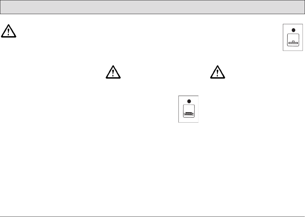
59
Operation
Check whether the floor is
sufficiently dry at regular
intervals, otherwise people
could slip. If the floor is
excessively wet, check the
vehicle for leaks and that the
sealing strips are in a good
condition. If the sealing strips
are damaged, change them;
refer to Section 5.8.4.
Wet scrubbing (basic cleaning)
If you do not want to vacuum the floor
dry in the same working procedure
because you want the solution to soak
into the dirt, for example, activate this
program.
Wet floors are a potential risk
for slipping! Ensure to provide
the corresponding information
and warning signs.
•Press the “Button for the
brush drive” (Fig. 21/9)
on the left-hand operating
panel.
Various functions can be
switched on or off with the following
buttons according to the conditions at
the location of use:
• Reduce water quantity (Fig. 26/2)
• Increase water quantity (Fig. 26/4)
• Fresh water feed on/off (Fig. 26/3)
• Increase brush pressure (Fig. 26/1)
Vacuuming dry
• Press the “Button for
squeegee and suction
turbine” (Fig. 21/10) on
the left-hand operating
panel.
Check whether the floor is
sufficiently dry at regular
intervals, otherwise people
could slip. If the floor is
excessively wet, check the
vehicle for leaks and that the
sealing strips are in a good
condition. If the sealing strips
are damaged, change them;
refer to Section 5.8.4.
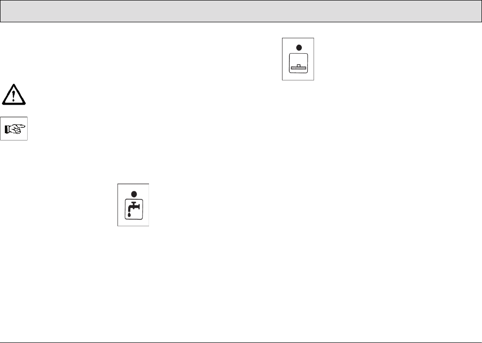
60
Operation
Vacuuming with the suction hose
The suction hose is an optional
accessory and part of the
spray/vacuum tool function.
When the suction hose is in
operation, the scrubber drier's
parking brake must be applied.
Vacuuming with the suction
hose only works when the
operator is not seated on the
driver's seat (seat contact
switch is not actuated) and the
parking brake is applied.
1. Press the “Button to
switch the fresh water
supply on and off”
(Fig. 21/14) on the left-
hand operating panel to
switch the water on and
off.
2. Press the “Button for
squeegee and suction
turbine” (Fig. 21/10) on
the left-hand operating
panel to switch the
suction turbine on and
off.
The squeegee remains raised.
Useful tips for cleaning
• Sweep the floor before starting wet
cleaning. This not only improves the
cleaning effect but also reduces the
vehicle's liability to wear.
• The floor should be treated twice in
the case of particularly dirty floors or
to remove wax (basic cleaning).
- During the first cleaning process,
the floor is scrubbed with a
cleaning agent dosage appropriate
to the degree of soiling, whereby
the squeegee is raised.
- Let the cleaning solution work into
the floor for 5 to 10 minutes
according to the manufacturer's
information.
- Then scrub the floor again with the
squeegee lowered.
• Observe the correct dosage of the
cleaning agent. Information on
dosage is provided on the cleaning
agent container.
• Use the manufacturer's information
as an initial basis. Practical
experience will ensure that you
quickly find out which is the right
PowerBoss cleaning agent and the
optimum dosage to suit your needs.
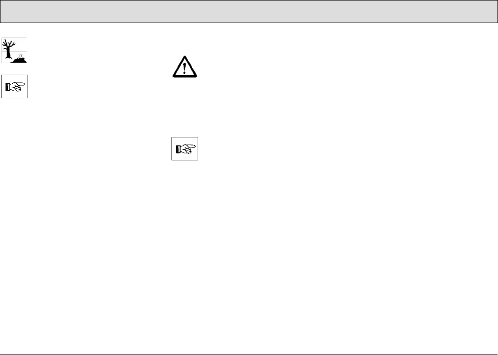
61
Operation
The correct dosage helps to
reduce costs and protect the
environment.
The development of excessive
foam impairs the vehicle's
function.
Cause: Too much cleaning
agent leads to certain
component parts of it getting
into the waste water resulting
in the development of foam.
This indicates that the amount
and mixture of solution do not
match the level of dirt.
3.3.5 Switching the vehicle off
Apply the parking brake!
1. Turn the key from position 1 to lock
position 0. The vehicle is no longer
ready to operate.
2. Remove the key from the key switch.
Check that the working lights
are switched off.
The working lights can be
switched on even when the
vehicle is switched off and,
thus, drain the battery.
3.3.6 Loading and transporting the
vehicle
Refer to Section 5.13.
62
Operation
3.4 After finishing work
1. Drive to a suitable service or parking
area.
An appropriate service and
parking area must have a solid
floor, have a roof and ensure
that no hazardous substances
(e.g. oils, battery acid, cleaning
agents, etc.) can get onto the
floor or in the sewage system.
2. Stop the vehicle and switch it off.
Before getting out of the
vehicle apply the parking
brake, switch off the key switch
and remove the key.
Check that the working lights
are switched off.
The working lights can be
switched on even when the
vehicle is switched off and,
thus, drain the battery.
3. Empty and clean the recovery tank,
refer to Sections 5.6.1 and 5.6.2.
Observe the applicable laws
and local regulations when
disposing of cleaning agents.
4. Check the fresh water filter, refer to
Section 5.5.4.
5. Check the sealing strips and suction
hose, refer to Section 5.8.
6. Check the electrical equipment,
functions and settings.
7. Clean the vehicle, refer to Section
5.12.
It is not permitted to clean the
vehicle with a pressure washer
or steam blaster.
8. Charge the batteries, refer to Section
5.4.1.
The seat console must remain
open during the charging
process (otherwise there is a
risk of oxyhydrogen
developing).
If the machine is to be
shutdown for a longer period,
the fresh water tank must be
emptied.

63
Operation
3.5 Function faults
The following applies when
locating and clearing faults:
Switch the vehicle off, remove
the key from the key switch
and disconnect the battery
plug!
3.5.1 Error code table
In the case of system errors, a four-digit
error code appears in the left-hand
operating panel in addition to the
service indicator (wrench symbol).
The dots in the error/service code flash.
Clear the fault or note down the
error/service code and inform your
authorized PowerBoss dealer.
Error code Fault Cause Solution
1.2.5.2. Brushes remain stopped
because the thermostatic
switch has been tripped.
The motor has overheated;
foreign bodies have possibly
jammed between the brush and
shaft (e.g. tape and such).
• Check the brushes for foreign bodies
and remove them, as necessary.
• Allow the motor to cool down.
• If the problem reoccurs, determine the
cause of overheating; contact an
authorized PowerBoss service center, if
necessary.
1.2.5.5. Brushes remain stopped
because the thermostatic
switch of the third, middle
brush has been tripped.
The motor has overheated;
foreign bodies have possibly
jammed between the brush and
shaft (e.g. tape and such).
• Check the brush for foreign bodies,
remove them as necessary.
• Allow the motor to cool down.
• If the problem reoccurs, determine the
cause of overheating; contact an
authorized PowerBoss service center, if
necessary.
1.2.6.1. Brushes remain stopped
because the anti-blocking
system has been tripped.
Foreign bodies (e.g. tape or
such) block the brushes
• Check the brushes for foreign bodies
and remove them, as necessary.

64
Operation
Error code Fault Cause Solution
1.2.6.2. Brushes remain stopped
because the anti-blocking
system of the third, middle
brush has been tripped.
Foreign bodies (e.g. tape or
such) block the brushes
• Check the brush for foreign bodies,
remove them as necessary.
1.2.6.3. The brush attachment and
brush motors have been
switched off because the
anti-blocking system has
been tripped.
Foreign bodies between the
brush head and vehicle.
• Check the brush head for foreign bodies
and remove them, as necessary.
1.4.6.1. Squeegee holding
attachment has been
switched off because the
anti-blocking system has
been tripped
• Foreign bodies between the
squeegee and vehicle.
• Squeegee is jammed
• Check the squeegee attachment for
foreign bodies and remove them, as
necessary
• Free the squeegee.
2.2.5.1 Cylindrical brush remains
stopped because the
thermostatic switch has
been tripped.
The motor has overheated.
Foreign bodies (e.g. tape or
such) possibly block the
cylindrical brush.
• Check the cylindrical brush for foreign
bodies and remove them, as necessary.
• Allow the motor to cool down.
• If the problem reoccurs, determine the
cause of overheating; contact an
authorized PowerBoss service center, if
necessary.
2.2.6.1 Cylindrical brush remains
stopped because the anti-
blocking system has been
tripped.
Foreign bodies (e.g. tape or
such) block the cylindrical brush.
Check the cylindrical brush for foreign
bodies and remove them, as necessary.
65
Operation
3.5.2 Other function faults
The vehicle does not work
Check the fuses, refer to Section
5.11.3.
In the event of faults in the
traction drive, stop the vehicle
immediately, apply the parking
brake and remove the key!
Error code Fault Cause Solution
2.2.6.2 Cylindrical brush holding
attachment has been
switched off because the
anti-blocking system has
been tripped.
Foreign bodies (e.g. tape or
such) between the cylindrical
brush and machine.
Check the cylindrical brush holding
attachment for foreign bodies, remove
them as necessary.
2.3.6.1 The left side brush remains
stopped because the anti-
blocking system has been
tripped.
Foreign bodies (e.g. tape or
such) block the side brush.
Check the side brushes for foreign bodies
and remove them, as necessary.
2.3.6.2 The right-hand side brush
remains stopped because
the anti-blocking system has
been tripped.
Foreign bodies (e.g. tape or
such) block the side brush.
Check the side brushes for foreign bodies
and remove them, as necessary.
3.4.5.1 Drive motor is too hot /
Drive motor switches to 50%
power output.
• Engine is overloaded, possibly
after driving up slopes.
• Parking brake was actuated
while driving.
• Allow the motor to cool down.
• Check whether the parking brake is
applied and release it, if necessary.

66
Technical Data
4Technical Data
Dimensions
Vehicle length (with brush head, squeegee and pre-sweep/vacuum unit) in 103.1
Vehicle height, without/with cab safety roof in 55.1/78.7
Vehicle width with squeegee and pre-sweep/vacuum unit in 52.4
Vehicle width with side collision protection option in 54.7
Working width
Brush head in 48.4
Squeegee in 49.6
Pre-sweep/vacuum unit in 54.3
Area coverage
Theoretical at 4.4 mph ft²/h 92677
Weights
Dead weight (without driving batteries, without options, without driver) lbs 2061
Total weight operational wet
(without options, without driver) lbs 3549
Gross total weight lbs 3968

Axle loads
Ready to use, front (fresh water tank full, including cab safety roof) lbs 1852
Ready to use, rear (fresh water tank full, including cab safety roof) lbs 1808
Driving performance
Driving speed, forwards/reverse mph 5.0/2.5
Working speed, maximum, forwards mph 4.4
Climbing capacity, transport mode (max. 15 seconds) % 15
Climbing capacity, work mode (max. 3 min) % 6
Turning circle diameter, outer ft 13.9
Turning in aisle: minimum aisle width ft 9.4
Operating time with one battery charge h approx. 2.5
Drive
Drive motor (P2) W 2000
Gear oil fill quantity gal/SAE 0.7/SAE 90
67
Technical Data

Axles and wheels
Wheelbase in 45.3
Gauge, rear in 34.6
Wheels, diameter/width in 12.2/4.7
Specific wheel pressure at permissible gross total weight, front ksi 0.178
Specific wheel pressure at permissible gross total weight, rear (left/right) ksi 0.129/0.128
Tightening torque of wheel nuts, front/rear lb ft 103.3/103.3
Brakes
Service brake: Hydraulic
Drum brakes at rear, with automatic adjustment: diameter/width in 7.1/1.6
Brake fluid (e.g. ATE) gal 0.1
Parking brake:
Cable brake at rear, adjustable: diameter/width in 7.1/1.6
Tank volume
Membrane panel tank: fresh/waste water gal 81.9/81.9
Flow rate, adjustable from/to gal/min. 0.3/2.0
68
Technical Data

Brush head
No. of brushes Qty. 3
Brush diameter in 16.9
Brush speed rpm 210
Brush motor power output (P2) W 3 x 710
Brush pressure, normal/increased lbs 150/205
Specific contact pressure normal/increased psi 0.3/0.42
Suction turbines
Power consumption/speed W/rpm 635/13867
Air flow rate ft3/h 8476
Vacuum psi (mmwc) 2.94 (2030)
Electrical installation
Power supply VDC 36
Type of current DC
Nominal power, total W 7600
Protection class VDE 0700 III
Battery compartment: length/width/height in 37.4/24.0/18.3
69
Technical Data

70
Technical Data
Noise emission value
The sound power level (LWAd) measured according to EN 60335-2-72 under
normal under working conditions is: dB (A) 90
The sound pressure level (LpA) measured according to DIN EN 60335-2-72 (at
the driver's ear) under normal working conditions is: dB (A) 76.5
Inaccuracy factor (KpA): dB (A) 2
Vibration
The weighted, effective value of the vibration, established in accordance with ISO
5349-1 to which the upper limbs (hand-arm) are exposed under normal working
conditions is: m/s2< 2.5
The weighted, effective value of the vibration and shock, established in
accordance with ISO 2631-1, to which the body (feet and seat area) are exposed
under normal working conditions is: m/s2< 0.5

71
Technical Data
Special equipment:
Driving batteries
Block battery V/Ah56 x 6/320 (CR395)
Weight (including battery tray) lbs 794
Chemical dosing system Order number 7564.02
Cab safety roof (including rear-view mirror) Order number 7582
Working lights, 2 pieces Order number 7584.02
V/W 2 x 24/70
Flashing beacon V 36
For installation on the cab safety roof Order number 7585.02
For installation on a pole (when no cab safety roof is available) Order number 7585.10
Collision protection
Side collision protection (2 pieces) Order number 7680.30
Side brush collision protection (2 pieces) Order number 7581.50

72
Technical Data
Special equipment:
Additional scrubbing and vacuuming tools (spraying-vacuuming tool)
Floor scrubbing tool Order number 7009
Vacuuming and spraying hose (length: 16.4 ft) Order number 7766
Tool holder and attachment part Order number 7311.10
Additional tools for using the suction hose (hand-held vacuum cleaner)
Adapter to connect the following tools Order number 7893
Suction hose (length: 9.8 ft) Order number 7880
Suction pipe (length: 4.3 ft) Order number 7881
Suction nozzle with rubber lips Order number 7883

73
Technical Data
Pre-sweep/Vacuum unit Order number 7581
Dirt hopper volume, theoretical/practical gal 13.2/5.3
Fill weight, maximum lbs 60
Filter surface ft216
Use category ZH 1/487 KAT U
Fan motor W 234
Extractor fan, speed rpm 3200
Air flow rate ft3/h 11830
Vacuum in brush space mmwc 8.0
Cylindrical brush drive motor (P1/P2) W 612/550
Cylindrical brush, length/diameter in 27.6/9.8
Cylindrical brush, minimum diameter in 7.1
Cylindrical brush speed rpm 510
Sweeping pattern width in 1.2-2.0
Side brush drive motor (P1) W 2x100
Side brush, diameter in 15.7
Side brush speed rpm 105

74
Technical Data
Special equipment:
Brushes (total of 3 are necessary)
5-component brush Order number 7685
Plastic PPN 0.5 for light to medium accumulations of dirt Order number 7806
Plastics mix K 901
for light to medium accumulation of dirt on structured floors Order number 7816
Plastic PPN 0.8 for light to heavy accumulations of dirt Order number 7836
SIC PA 6 grain 180 gray
for basic cleaning and very heavy accumulation of dirt Order number 7843
SIC PA 6.12 grain 120 green
for basic cleaning and extreme accumulation of dirt Order number 7845
SIC PA 6 grain 600 gray Order number 7826
Superpads (total of 3 are necessary)
Drive plate (pad holder) with centerlock Order number 7857
Pads, red for routine cleaning (5 pieces in box) Order number 7838.05
Pads, brown for routine cleaning (5 pieces in box) Order number 7837.05
Pads, black for basic cleaning and heavy accumulations of dirt
(5 pieces in box)
Order number 7840.05
Microfiber pad Order number 7850.02

75
Maintenance and Service
5 Maintenance and
Service
General information
It is essential to pay attention
to the information in Chapter
"Safety Information" before
completing any service or
maintenance work!
By adhering to the maintenance work
recommended by us, you can be sure
that the vehicle is always ready to be
put into operation.
Maintenance and repair work
necessary on a daily and weekly basis
can be carried out by a driver trained to
complete the work, all other PowerBoss
system maintenance may only be
completed by personnel who are
correspondingly qualified and trained.
In case of doubt, please contact your
nearest PowerBoss service center or
authorized PowerBoss dealer. Failure
to observe this annuls any rights to
claims under the terms of guarantee in
respect of resulting damage or
consequential damage.
Always specify the serial number,
indicated on the rating plate, when
making any inquiries and orders for
spare parts, refer to Section 1.7.
5.1 PowerBoss system
maintenance
PowerBoss system maintenance:
• ensures the PowerBoss working
vehicle is always ready for operation
(preventive maintenance),
• minimizes operating costs,
maintenance and repair costs,
• ensures the vehicle has a long
service life.
The PowerBoss system maintenance
describes the specific technical work
necessary for the individual modules
and defines the intervals for the
maintenance tasks. Individual parts
which must be changed during
maintenance tasks are defined and
stipulated in spare parts kits.
PowerBoss system maintenance,
customer:
Work to be carried out by the customer
according to the service and
maintenance instructions in the
operating manual (daily and weekly).
Operating personnel are given the
necessary instruction by specialists
when the vehicle is delivered.
PowerBoss system maintenance I:
(Every 250 operating hours or at least
once a year)
Must be completed by a skilled
technician in an authorized PowerBoss
service center according to the vehicle-
specific system maintenance with a
spare parts kit.
PowerBoss system maintenance II:
(Every 500 operating hours or at least
once a year)
Must be completed by a skilled
technician in an authorized PowerBoss
service center according to the vehicle-
specific system maintenance with a
spare parts kit.
PowerBoss system maintenance
III/S:
(Safety check, every 1000 operating
hours or at least once a year)
Must be completed by a skilled
technician in an authorized PowerBoss
service center according to the vehicle-
specific system maintenance with a
spare parts kit.

76
Maintenance and Service
5.2 Maintenance report
Handover
Upgrading
Test drive
Handover to customer
Instruction
completed on:
at _________________ operating hours
PowerBoss
System Maintenance I
250 operating hours
Workshop Stamp
completed on:
at _________________ operating hours
PowerBoss
System Maintenance II
500 operating hours
Workshop Stamp
completed on:
at _________________ operating hours
PowerBoss
System Maintenance I
750 operating hours
Workshop Stamp
completed on:
at _________________ operating hours
PowerBoss
System Maintenance III/S
1000 operating hours
Workshop Stamp
completed on:
at _________________ operating hours
PowerBoss
System Maintenance I
1250 operating hours
Workshop Stamp
completed on:
at _________________ operating hours
PowerBoss
System Maintenance II
1500 operating hours
Workshop Stamp
completed on:
at _________________ operating hours
PowerBoss
System Maintenance I
1750 operating hours
Workshop Stamp
completed on:
at _________________ operating hours
PowerBoss
System Maintenance III/S
2000 operating hours
Workshop Stamp
completed on:
at _________________ operating hours
PowerBoss
System Maintenance I
2250 operating hours
Workshop Stamp
completed on:
at _________________ operating hours
PowerBoss
System Maintenance II
2500 operating hours
Workshop Stamp
completed on:
at _________________ operating hours
PowerBoss
System Maintenance I
2750 operating hours
Workshop Stamp
completed on:
at _________________ operating hours

77
Maintenance and Service
5.3 Maintenance schedule
5.3.1 PowerBoss system
maintenance, customer
The following maintenance work must
be completed by the customer at the
intervals stipulated.
It relates to the daily and weekly
maintenance work.
Activity Interval
Daily
Directly prior to starting operation:
Fill the fresh water tank (dose the cleaning agent, fill fresh water) o
Before or after operation:
Check the properties of the deflectors to the right and left and repair them or replace the deflector
rubber (left and right) as necessary o
Check the service brake in terms of its functionality and for signs of leaks; repair as necessary o
Check the parking brake in terms of its functionality and for signs of leaks; repair as necessary o
Check the squeegee is clean and for signs of damage; pay special attention that the support rollers run
smoothly and for foreign bodies, clear as necessary o

78
Maintenance and Service
After the end of operation:
Empty the recovery tank o
Clean the recovery tank o
Clean the air intake filter in the recovery tank o
Clean the fresh water filter o
Empty the dirt hopper on the pre-sweep/vacuum unit (several times a day, if necessary) o
Clean the dirt hopper of the pre-sweep/vacuum unit o
Check the battery charge; recharge as necessary o
Activity Interval
Daily

79
Maintenance and Service
Before completing the weekly
maintenance work described
below,
subject all the operating elements to a
function test in order to check whether
the vehicle is ready for operation.
Activity Interval
Weekly
Check the acid level of the battery and refill distilled water as necessary o
Check the electrical system (including working lights) and repair any defects o
Brush head: Check the deflectors on the right and left and complete any repairs or order spare parts
and replace them as necessary o
Check the squeegee, particularly the rear sealing strip, is clean and for signs of damage and wear and
complete any repairs or order spare parts and replace them as necessary o
Check the recovery tank through the inspection hole at the top for signs of premature wear (due to
glass splinters, metal chips, grit, etc.) or damage and clean it o
Check the vehicle is clean; clean it, if necessary o
Check the brushes for signs of wear; change, if necessary o
Complete a test drive and function test (including brake tests) o

80
Maintenance and Service
5.3.2 PowerBoss system
maintenance I The following maintenance work must
be completed by an authorized
PowerBoss service center.
Activity Interval
Every 250 operating hours
Check the battery in terms of acid level, acid density and voltage per cell; clear up any defects as
necessary o
Change the gear oil in the drive motor o
Grease the rotary joint o
Check the service brake for leaks, check the main brake cylinder and actuating rods, clear any
defects o
Check the brake fluid in the service brake, top up as necessary, bleed
(Note: brake fluid must be changed every 2 years!) o
Subject the service brake to a brake tests; clear any defects as necessary o
Check the parking brake for actuating play; repair as necessary o
Subject the safety catch to a function test (to release the parking brake) o
Check the steering for steering play and adjust as necessary o
Lubricate and grease the steering o

81
Maintenance and Service
Check the torque of the wheel nuts; adjust as necessary o
Check the scrubbing unit and service as necessary: brushes, water retaining ring, brush catches,
parallel alignment of holding attachment o
Check the deflectors on the scrubbing unit and replace them as necessary (left and right) o
Grease the scrubbing unit joints and connecting rods o
Check the recovery tank, particularly the lid sealing quality and filter sieve o
Change the O-rings in the draining hose and dosing valves o
Check the suction hose is fitted properly and for signs of damage; clear any defects as necessary o
Test the squeegee functions: pivot, raise/lower, deflecting rollers o
Check the front and rear sealing strips of the squeegee; change as necessary o
Activity Interval
Every 250 operating hours

82
Maintenance and Service
Check the knurled nuts on the squeegee; change as necessary o
Grease the joints and connection rods of the waste water vacuuming system o
Adjust the support rollers on the squeegee o
Check the vacuum at the suction hose; clear any defects o
Check the electrical safety functions: parking brake, recovery tank float switch o
Pre-sweep/vacuum unit: Check the tension and properties of the cylindrical brush drive fan belt;
retension or change as necessary o
Pre-sweep/vacuum unit: Check the cylindrical brush for signs of wear and foreign bodies (e.g.
tape, wire, etc.), replace cylindrical brush if necessary o
Pre-sweep/vacuum unit: Check the brush swings smoothly o
Pre-sweep/vacuum unit: Check the sweeping pattern o
Pre-sweep/vacuum unit: Check the cylindrical brush setting; adjust if necessary o
Pre-sweep/vacuum unit: Check the sealing strips in the brush space; change any defective
sealing strips o
Pre-sweep/vacuum unit: Check side brush bristles for wear; change if necessary o
Pre-sweep/vacuum unit: Check the filter system for leaks; disassemble the filter element
and clean it, change the filter element if defective o
Pre-sweep/vacuum unit: Check the functionality of the agitating motor and extractor fan motor o
Activity Interval
Every 250 operating hours

83
Maintenance and Service
Check the vehicle's condition visually:
color, corrosion and presence of all signs and labels o
Check the vehicle is clean; clean it, if necessary o
Test drive and test all function and safety-relevant component including brake tests o
Inspection label o
Logbook o
On request against separate account: driver training o
Activity Interval
Every 250 operating hours

84
Maintenance and Service
5.3.3 PowerBoss system
maintenance II The following maintenance work must
be completed by an authorized
PowerBoss service center.
Activity Interval
Every 500 operating hours
Complete all activities in PowerBoss system maintenance I, see paragraph 5.3.2 o
In addition:
Check the brake linings of the service brake for wear; readjust the service brake or change the
brake linings as necessary o
Check the output of the drive motor (forwards, reverse); clear defects as necessary o
Check the carbon brushes of the drive motor; replace, if necessary o
Check the performance of the three brush motors; clear any defects as necessary o
Check the carbon brushes of the brush motors; replace, if necessary o
Including visual inspection, test drive, test report, inspection label and logbook
see paragraph 5.3.2 o

85
Maintenance and Service
5.3.4 PowerBoss system
maintenance III/S (safety
check)
The following maintenance work must
be completed by an authorized
PowerBoss service center at least once
a year.
Activity
Interval
Every 1000 operating
hours
Complete all activities in PowerBoss system maintenance I and II,
see paragraph 5.3.2 and paragraph 5.3.3 o
In addition: o
Check the brake linings on the rear wheels; change as necessary o
Change the brake fluid in the service brake
(Note: brake fluid must be changed every 2 years!) o
Check the parking brake including pedal lock and control lamp; clear any defects o
Grease the rotary joint of the traction drive (2 lubrication points accessible from the bottom) o
Clean carbon dust from the electric motors of the wheel brush, suction turbine and cylindrical
brush drives and check the carbon brushes move easily and for signs of wear,
change the carbon brushes, if necessary
o
Safety test, drive electronics o
Including visual inspection, test drive, test report, inspection label and logbook
see paragraph 5.3.2 o
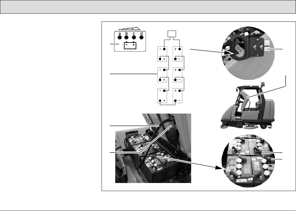
86
Maintenance and Service
5.4 Battery system
The scrubber-drier is operated by
means of a low-maintenance tray
battery, refer to Sections 3.1.9 and 4.
The battery is comprised of 6 individual
cells (monobloc batteries) in a serial
circuit.
1 Battery and charge control indicator
(including BMS indicator)
in left operating panel
2 Wiring diagram
3 Battery connection cable
4 Battery plug in vehicle socket
5 Battery plug (disconnected)
6 Seat console, open
7 Battery interconnection cable
8 Insulation cap
Fig. 27
1
2
5
6
8
7
3
4
87
Maintenance and Service
General information on handling
batteries
Pay attention to the safety
information in Section 1.4 and
Section 1.5.2 as well as the
information on servicing and
maintenance in the battery
documents.
Also refer to the information in
the supplementary sheet 88-
60-2556 "Information on
driving batteries".
• Always disconnect the battery plug
before starting any work on the
electrical installation.
• Batteries may only be handled and
changed by properly skilled
maintenance personnel.
• Pay attention to legal requirements
and local directives.
5.4.1 Charging batteries
Before starting the vehicle up
for the first time, the batteries
to be used must be properly
charged by implementing the
initial battery charge routine,
refer to Section 2.2.
PowerBoss assumes no
liability for damage to the
battery caused by a fault when
the battery is charged for the
first time.
There must be sufficient
ventilation in the charging area
- risk of explosion!
The seat console (Fig. 27/6)
must be open during the
battery charging process to
prevent the development of
explosive oxyhydrogen!
Only use the original charger
and original adapter! Pay
attention that the insulation is
not initially damaged and not
damaged during the charging
process. The cable must not
rub against anything. Do not
use the charger if the insulation
is damaged.
We recommend charging the battery
when at least one dot of the battery
indicator has gone out after operating
the machine. The indicator (Fig. 27/5)
also indicates the charge status of the
batteries during the charging process.
1. Connect the battery plug (Fig. 27/4)
to the adapter supplied.
2. Connect the free plug on the adapter
to the battery charger.
The battery charger is not
contained in the scope of
delivery of the vehicle.
Pay attention to the
information in the operating
manual supplied with the
charger and the manual from
battery manufacturer.
Do not inhale battery gases.
88
Maintenance and Service
5.4.2 Servicing the driving batteries
Checking the acid level
The battery acid level must be checked
by the customer on a weekly basis and
distilled water must be topped up, if
necessary; also refer to Sections 5.3.1
and 5.3.2.
There must be no naked
flames used in the vicinity
when handling batteries,
particularly when checking the
acid level.
Details on the filling process are
contained in the manual provided with
the water filling device.
Spilled battery acid must never
enter the sewage system in its
initial form, it must be
neutralized beforehand: e.g.
diluted with plenty of water or
absorbed with granulate.
Checking the acid density and
voltage of each cell
These points must be checked and
corrected at regular intervals within the
scope of PowerBoss system
maintenance by an authorized service
center.
Also refer to the information in
the supplementary sheet 88-
60-2556 "Information on
driving batteries".
5.4.3 Disassembling the battery
1. Park the vehicle on a level area of
floor.
Turn the key switch to position
0 and remove the key.
2. Open the side doors to the left and
right (Fig. 28/3).
3. When you are positioned on the
right-hand side of the vehicle, take
hold of the seat console at the
handle (Fig. 28/2) and pivot up
towards the front.
Pivot the seat console
(Fig. 28/1) open from the right-
hand side of the vehicle,
otherwise your hands could be
crushed between the seat
console and cab safety roof (if
fitted).
4. Disconnect the battery and vehicle
plug (Fig. 28/4+5).
When disassembling the
batteries, use appropriate
lifting gear.
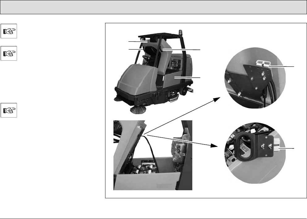
89
Maintenance and Service
The battery may only be
disassembled using lifting gear
by properly trained personnel.
If the scrubber-drier is
equipped with a cab safety
roof, lift the batteries out on the
left-hand side of the battery.
The cab safety roof has a
recess for the lifting gear rope.
5. Lift the batteries out of the vehicle
using a lifting gear.
Guide the lifting gear from the
left to the battery.
Fig. 28
2
1
3
2
4
5
90
Maintenance and Service
5.4.4 Installing the battery
Set the key switch to position 0
(refer to section ”Key switch” in
Section 3.2.3) and remove the
key.
1. Open the side doors to the left and
right (Fig. 28/3).
2. Take hold of the seat console
(Fig. 28/1) at the handle (Fig. 28/2)
and pivot it forwards to open it.
If a cab safety roof is fitted,
open the seat console from the
right-hand side of the vehicle,
otherwise your hands could be
crushed between the seat
console and cab safety roof.
Install the 6 monobloc batteries into the
tray in the vehicle from the left-hand
side of the vehicle using lifting gear or a
fork-lift truck according to Figure 28.
If the scrubber-drier is fitted
with a cab safety roof, the
battery can only be installed
from the left-hand side of the
vehicle; the cab safety roof is
provided with a recess for the
lifting gear rope.
When installing the battery,
use appropriate lifting gear.
The battery may only be
installed using lifting gear by
properly trained personnel.
Connect the battery plug (Fig. 28/5) and
vehicle socket (Fig. 28/4) to each other.
Ensure they are connected firmly.
5.4.5 Disposing of batteries
Used batteries with the recycling
symbol contain reusable commodities.
The heavy metals contained represent
a major risk both to people's health and
to the environment. Never open or
damage batteries. Never touch, inhale
or swallow the content of batteries.
Health hazard! Do not allow batteries to
get into the environment. Risk of
contaminating the ground and water!
In accordance with symbol with the
crossed out garbage bin, these
batteries must not be disposed of in
domestic waste. Return and recycling
of old batteries must be agreed on with
the authorized PowerBoss dealer in
accordance with national requirements.

91
Maintenance and Service
5.4.6 Deep discharge signal
transducer (BMS)
The scrubber drier is equipped with a
charge control for protection against
deep discharge of the batteries. The
deep discharge signal transducer
(BMS) is integrated in the electronic
system and setup at the factory for
battery type GiS (digit in the service
indicator: No. 5). If other batteries are
used, the deep discharge signal
transducer must be adjusted.
The deep discharge signal
transducer may only be
adjusted by an authorized
PowerBoss service center.
Also refer to Section 3.1.9.
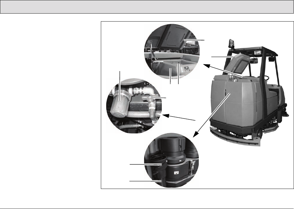
92
Maintenance and Service
5.5 Fresh water tank
1 Lid seal
2 Lid
3 Opening to recovery tank
(airing and venting)
4 Fresh water tank
5 Fresh water filter
6 Ball cock
7 Lock
8 Fresh water draining hose
Fig. 29
4
1
2
5
6
8
3
7
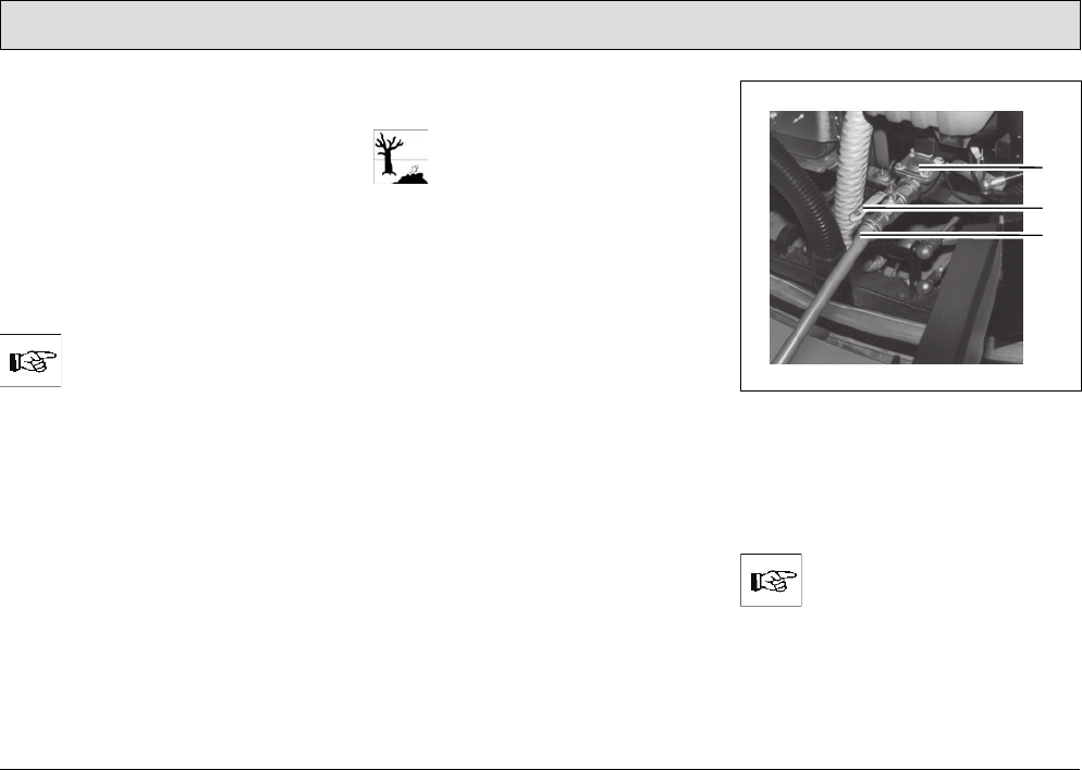
93
Maintenance and Service
5.5.1 Filling the fresh water tank
Fill the fresh water tank (Fig. 29/4)
with
fresh water and cleaning agent before
starting with the work, also refer to
Section 3.1.5.
1. Park the machine on a level floor
area.
2. Open the tank lid (Fig. 29/2) and lock
in place.
3. Fill the fresh water tank to the
maximum mark.
Only fill water at maximally
122 °F!
4. Mix cleaning agent in accordance
with the manufacturer's instructions.
5. Close the lid (Fig. 29/2) on the fresh
water tank.
Filling the fresh water tank via the
automatic filling device
Please observe the guidelines
provided by the water supply
company. The vehicle must not
be connected directly to a
public drinking water supply to
prevent chemicals getting into
the drinking water supply. A
brief connection is permitted,
however, if a backflow
preventer with pipe aerator is
installed in the supply line. A
backflow preventer of the type
EA 3 or EA 2 must be installed.
1. Open the rear doors on the left and
right as well as the rear panel frame
(Fig. 23/7-9).
2. Connect a filling hose (Fig. 30/3)
with a connection diameter of 0.7 in
(3/4 inch).
Fig. 30
3. Open the ball cock (Fig. 30/2).
4. Press the button for the solenoid
valve (Fig. 30/1). This is located
under the suction turbine.
The button for the solenoid
valve (Fig. 30/1) can also be
actuated when the key switch
is switched off.
1
2
3

94
Maintenance and Service
5. Open the water tap on site.
Only fill water at maximally
122 °F!
On reaching the maximum fill level, the
float switch in the fresh water tank
closes the solenoid valve automatically.
Check the float switch regularly
for soiling!
6. Close the water tap on site.
7. Close the ball cock (Fig. 30/2).
8. Disconnect the filling hose
(Fig. 30/3).
9. Close the rear doors on the left and
right as well as the rear panel frame
(Fig. 23/7-9).
10.Close the lid (Fig. 29/2) on the fresh
water tank.
11.Mix cleaning agent in accordance
with the manufacturer's instructions.
12.Close the lid (Fig. 29/2) on the fresh
water tank.
5.5.2 Emptying the fresh water tank
If the vehicle is to be left unused for a
longer period, the fresh water tank
(Fig. 29/4) should be emptied.
1. Park the vehicle so that the draining
hose for fresh water (Fig. 29/8) can
be positioned over a drain in the
floor.
2. Open the left and right rear doors.
3. Open the rear panel frame.
4. Detach the fresh water draining hose
(Fig. 29/8) and lower it slowly.
5. Unscrew the cap (Fig. 29/7) to open
it. The quantity drained can be
regulated by turning the screw cap
and pivoting the cap open fully, if
necessary.
6. When the fresh water tank has been
completely emptied, screw the cap
shut again and attach the draining
hose again.
7. Close the rear panel frame.
8. Close the left and right rear doors.
When disposing of the waste
water containing the cleaning
agent, observe all applicable
legal regulations.
5.5.3 Cleaning the draining hose
cap
•The screw cap (Fig. 29/7) at the end
of the draining hose (Fig. 29/8)
should be cleaned at regular
intervals.
• Lubricate the O-ring lightly, if
necessary.
5.5.4 Cleaning the fresh water filter
The fresh water supply is equipped with
a filter (Fig. 29/5) which must be
cleaned if dirt appears on the container.
This is located on the left-hand side of
the vehicle at the height of the brushes
behind the side panel.
1. Close the ball cock (Fig. 29/6) to
prevent fresh water being supplied
from the tank.
2. Unscrew the container by hand and
pull the sieve insert out downwards.
3. Clean both parts with water and
reassemble them.
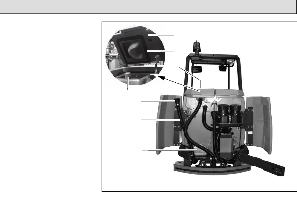
95
Maintenance and Service
5.6 Recovery tank
1 Lid
2 Lid seal
3 Recovery tank
4 Air intake filter
5 Lock
6 Waste water draining hose
7 Cleaning flap
Fig. 31
6
4
7
3
1
2
5
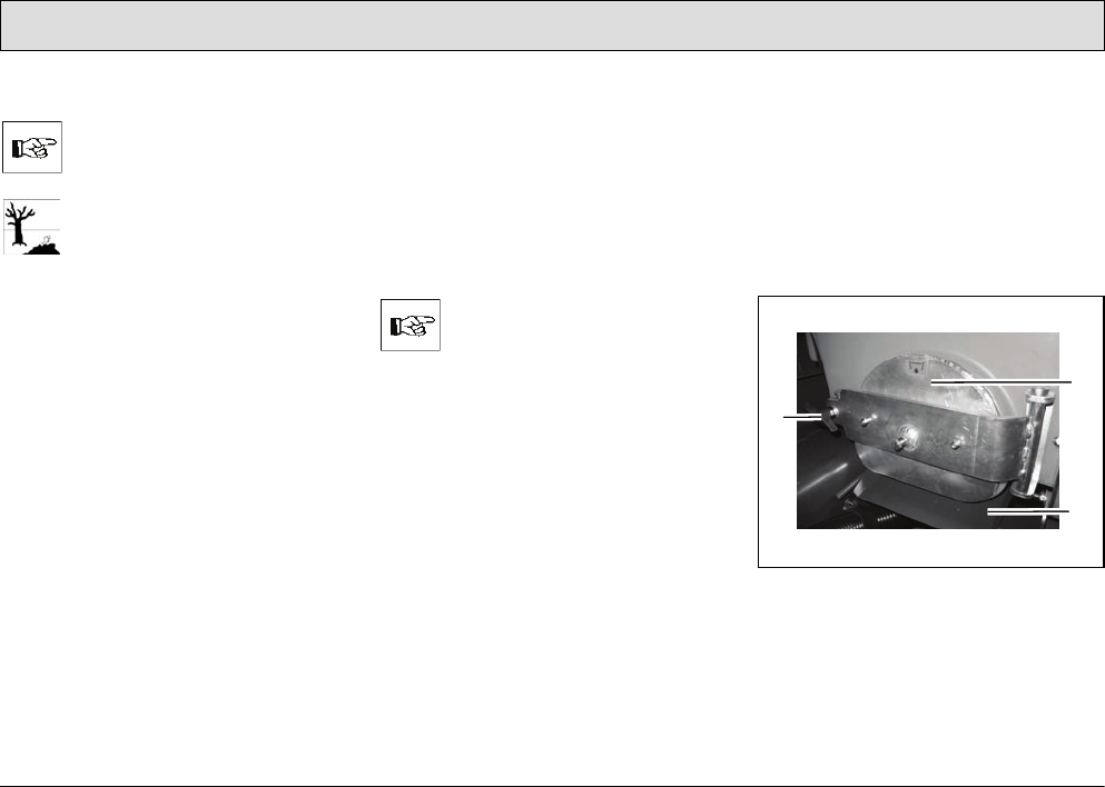
96
Maintenance and Service
5.6.1 Emptying the recovery tank
The recovery tank (Fig. 31/3)
must be emptied and flushed
clean after finishing work.
Observe the applicable laws
and local regulations when
disposing of waste water
containing cleaning agents!
1. Park the vehicle so that the waste
water draining hose (Fig. 31/6) can
be positioned over a drain in the
floor.
2. Open the left and right rear doors.
3. Open the rear panel frame.
4. Detach the waste water draining
hose (Fig. 31/6) and lower it slowly.
5. Unscrew the cap (Fig. 31/5) to open
it. The quantity drained can be
regulated by turning the cap and
pivoting the cap open fully, if
necessary.
6. When the recovery tank has been
completely emptied, screw the cap
shut again and attach the draining
hose again.
If the recovery tank is
extremely dirty, begin cleaning
the tank straight away.
7. Close the rear panel frame.
8. Close the left and right rear doors.
5.6.2 Cleaning the recovery tank
Clean the recovery tank (Fig. 31/3)
every day or as necessary. The
cleaning flap (Fig. 31/7)
is available for
this.
1. Open the left and right rear doors.
2. Open the rear panel frame.
3. Empty the recovery tank, refer to
Section 5.6.1.
Fig. 32
4. Pull out the run-off plate (Fig. 32/3).
5. Release the flap lock: turn the wing
nuts (Fig. 32/1) counterclockwise.
6. Open the cleaning flap (Fig. 32/2).
2
3
1
97
Maintenance and Service
7. Open the recovery tank lid
(Fig. 31/1).
8. Flush the recovery tank with water
filled from the top through the open
tank lid.
Cleaning may only be carried
out using a water hose
(operating pressure approx.
72.51 to 87.01 psi) and only
from top to bottom. Do not aim
the jet of water directly at
openings, slits, electronic
components, operating panels
or seals.
It is not permitted to clean the
vehicle with a high-pressure
washer or with a steam blaster
because the temperature is in
excess of 212 °F.
Wear appropriate gloves for
protection against dirt, viruses,
bacteria etc. when cleaning the
container.
9. After finishing cleaning the tank,
close the flap and push the run-off
plate back in place.
10.Unhook the waste water draining
hose (Fig. 31/6), lower it slowly and
open the cap (Fig. 31/5).
11.Run fresh water in the recovery tank
through the open lid using a water
hose (output pressure approx. 72.51
to 87.01 psi) and, in doing so, also
flushing the draining hose (see
above).
12.Screw the cap shut again and hook
the draining hose back in place.
13.Close the rear panel frame.
14.Close the left and right rear doors.
The cleaning flap must not be
used to drain off waste water.
5.6.3 Cleaning the draining hose
cap
• Clean the screw cap on the waste
water draining hose (Fig. 31/6) daily.
• Lubricate the O-ring lightly, if
necessary.
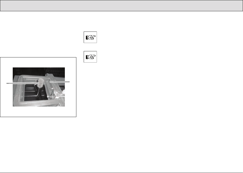
98
Maintenance and Service
5.6.4 Cleaning the air intake filter
The filter sieve (Fig. 33/1) is located in
the recovery tank above the maximum
water level on the suction pipe. The
accumulation of dirt in the filter sieve
must be checked daily and cleaned as
necessary:
Fig. 33
1. Pull the filter sieve from the suction
pipe and clean with water.
Remove the filter sieve
completely to clean it.
During cleaning and operation,
pay attention that no water and
no particles of dirt get into the
suction pipe and into the
suction turbines.
2. Dry the filter sieve after cleaning. Do
not replace when dripping wet!
5.6.5 Cleaning the openings to the
fresh water tank
The openings between the recovery
and fresh water tank (Fig. 33/2) serve
for ventilation between the two tanks.
They must be checked regularly for
accumulations of dirt and cleaned as
necessary.
2
1
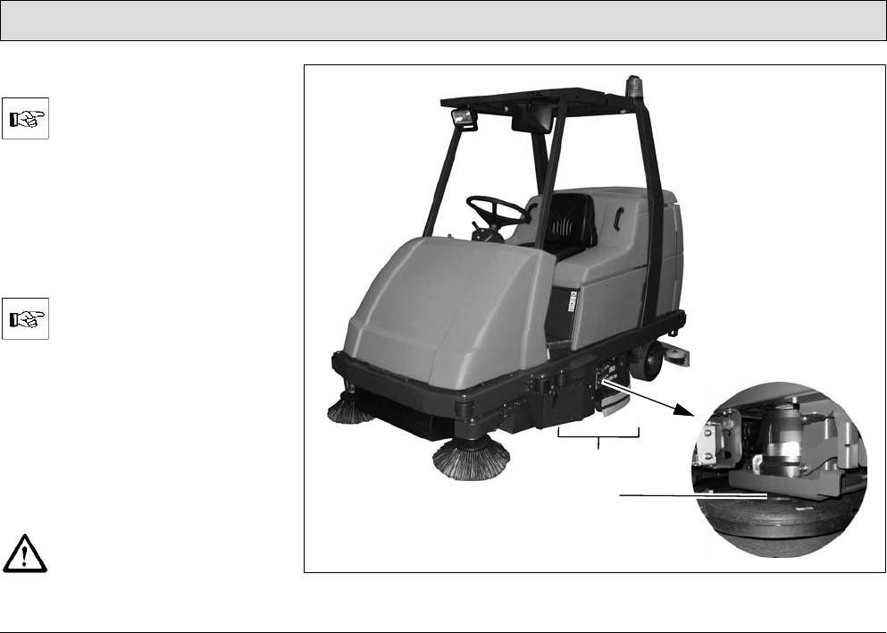
99
Maintenance and Service
5.7 Scrubbing unit
The scrubbing unit (Fig. 34/1)
may only be disassembled and
assembled by properly trained
service personnel.
The brushes, part of the scrubbing unit,
are not contained in the scope of
delivery. Select the brushes according
to your needs and install them on the
brush head (Fig. 34/2) according to the
instructions, refer to Section 2.3.1.
Please refer to Chapter 4 or
our spare parts catalogue on
our internet site at
www.powerboss.com for
brushes etc.
5.7.1 Changing the brushes
• Check the brushes on the brush
head weekly for signs of wear.
• When the brushes have worn to a
bristle length of 0.6 in, the brushes
must be replaced, refer to Section
2.3.1.
Before working on the brushes,
switch off the scrubbing unit,
turn the key switch to position 0
and remove the key. Fig. 34
1
2
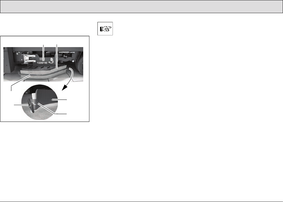
100
Maintenance and Service
5.7.2 Installing new rubber
deflector strips
Fig. 35
1 Deflectors
2 Rubber deflector strips
3 Clamping rail
4 Clamping rail hooks
5 Wing nuts
The deflector (Fig. 35/1) must
be fixed in its service position
(refer to Section 2.3.1, Point 1).
1. Unscrew the wing nut (Fig. 35/5) at
the end of the deflector.
2. Slide the clamping rail (Fig. 35/3) in
the vehicle's driving direction
(forwards) until the clamping rail
hooks (Fig. 35/4) are freed and the
clamping rail (Fig. 35/3) can be
removed away from the vehicle.
3. Remove the old rubber deflector
strips (Fig. 35/2).
4. Position the new rubber deflector
strips (Fig. 35/2) in place.
5. Mount the clamping rail (Fig. 35/3)
from the outside and slide back by
hand so that the clamping rail hooks
(Fig. 35/4) engage.
Screw the wing nut (Fig. 35/5) on the
thread at the end of the clamping rail
(Fig. 35/3), thus tightening the clamping
rail (Fig. 35/3).
12
34
5
4
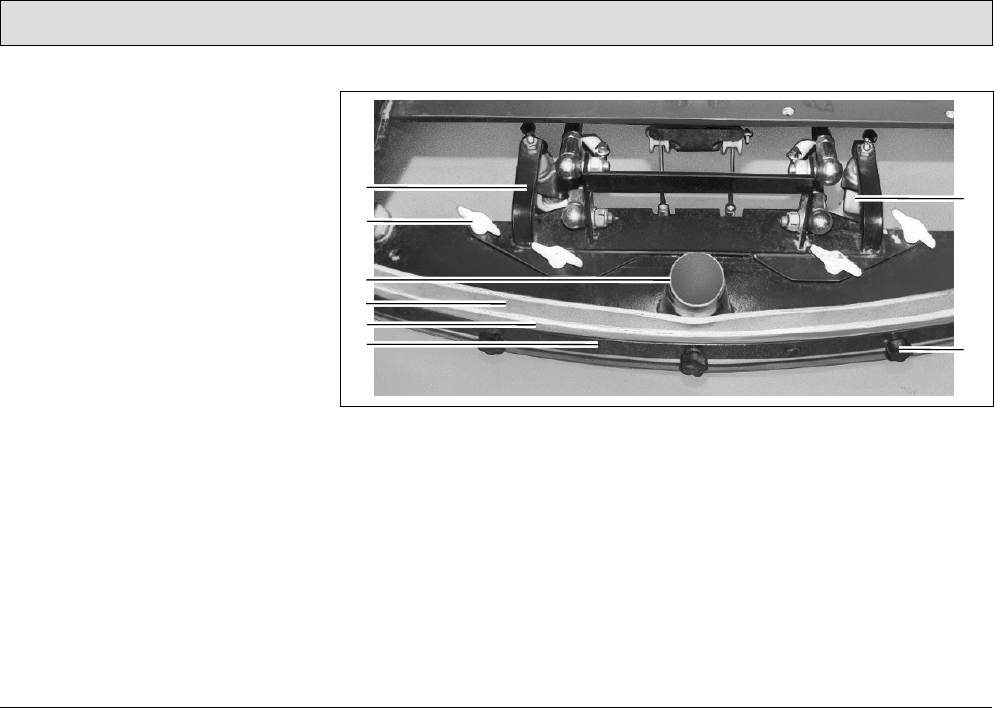
101
Maintenance and Service
5.8 Squeegee
1 Squeegee holding attachment
2 Wing nuts
3 Connection nozzle
4 Sealing strip (rear)
5 Support strip (rear)
6 Clamping rail (rear)
7 Support roller
8 Knurled nut
The squeegee is also equipped with
front sealing and support strips and
clamping rail (Fig. 37).
5.8.1 Cleaning the squeegee
Inspect the squeegee when raised daily
and clean as necessary.
5.8.2 Disassembling the squeegee
1. Insert the key in the key switch and
turn the key switch on.
2. Lower the squeegee: Press the
button for the squeegee and suction
turbine so that the green control
lamp lights up.
Fig. 36
3. Switch off the key switch and remove
the key.
4. Open the rear doors.
5. Pull the suction hose from the
connection nozzle (Fig. 36/3) of the
squeegee.
6. Loosen the wing nuts (Fig. 36/2) on
the holding attachment.
7. Pull the squeegee away to the rear
under the holding attachment.
8. Insert the key in the key switch and
turn the key switch on.
9. The squeegee is raised
automatically.
10.Close the rear doors.
2
3
4
1
5
6
7
8
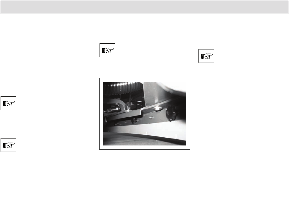
102
Maintenance and Service
5.8.3 Installing the squeegee
Refer to Section 2.3.2.
5.8.4 Changing the sealing strips
The sealing strips (Fig. 36/4) can be
changed without the need for any tools:
1. Disassemble the squeegee, refer to
Section 5.8.2
2. Unscrew the knurled nuts
(Fig. 36/8).
3. Remove the sealing strip, support
strip and clamping rail (Fig. 36/4-6).
Both sides of the sealing strip
can be used.
4. Install the new or reversed sealing
strips in the reverse working
sequence.
Pay attention that both sealing
strips (front and rear) touch the
floor when mounted.
5. Tighten the knurled nuts (Fig. 36/8)
evenly, starting from the center and
working on alternate sides.
There must be no bends in the
sealing strip.
6. Disassemble the front sealing strip
(Fig. 37) in the same way.
Fig. 37
7. After changing the sealing strips,
check that the squeegee stands
vertically on the floor. Otherwise,
readjust the support rollers.
When the vehicle is in
operation, the sealing strips
must be bent a little to the rear
when the squeegee is lowered.

103
Maintenance and Service
5.8.5 Adjusting the support rollers
The squeegee stands with the sealing
strips (Fig. 36/4) and support rollers
(Fig. 36/7) on the ground. To increase
the squeegee contact surface of the
sealing strips (Fig. 36/4) on the floor,
e.g. following wear of the sealing strips
(Fig. 36/4), the support rollers
(Fig. 36/7) must be set higher:
1. Position the squeegee of a level,
solid surface.
2. Loosen the counternuts in each
support roller.
3. Adjust the support rollers (Fig. 36/7)
on the right and left evenly:
- Turn the screw counterclockwise to
raise the support roller.
- Turn the screw clockwise to lower
the support roller.
4. Check the squeegee contact surface
and adjust, if necessary.
5. Tighten the counternuts on each
support roller (Fig. 36/7).
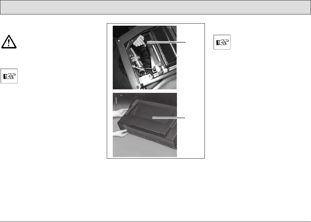
104
Maintenance and Service
5.9 Pre-sweep/Vacuum unit
Set the key switch to position 0
for all maintenance and repair
work to prevent starting up the
vehicle inadvertently!
5.9.1 Emptying the dirt hopper
The dirt hopper must be
emptied and cleaned at least
once a day. If the vehicle is
used for several hours a day,
the dirt hopper must be
checked and correspondingly
more frequently emptied.
Fig. 38
1 Lock
2Dirt hopper
(The top picture in Figure 38 illustrates
the position of the left-hand lock when
the front hood is open.)
Removing the dirt hopper
Only remove the hopper in the
direct vicinity of the refuse
dump/collection container.
1. When the front hood is closed, press
the right and left locks (Fig. 38/1) of
the dirt hopper (Fig. 38/2) up to
release the lock. The dirt hopper
pivots down.
2. Take hold of the dirt hopper
(Fig. 38/2) in both hands using the
grips located at the sides of the dirt
hopper (Fig. 38/2).
3. Pull the dirt hopper (Fig. 38/2) to the
front and out of the guide rails.
1
2
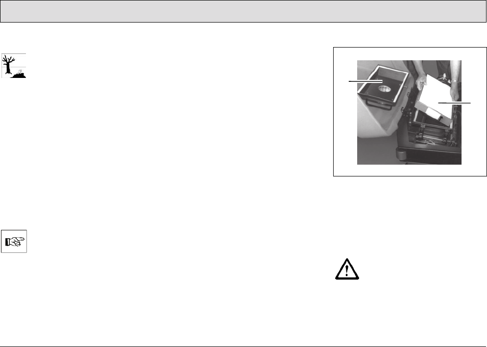
105
Maintenance and Service
Emptying the dirt hopper
Observe the applicable laws
and local regulations in respect
of disposal!
Empty the content of the dirt hopper
(Fig. 38/2) in a waste container at
regular intervals.
Installing the dirt hopper
1. Take hold of the dirt hopper
(Fig. 38/2) in both hands using the
grips located at the sides of the dirt
hopper (Fig. 38/2).
2. Fit the dirt hopper (Fig. 38/2) in the
guide rails, slide in as far as possible
and press the dirt hopper (Fig. 38/2)
upwards until the lock audibly
latches into place.
If the dirt hopper (Fig. 38/2) is
not properly engaged, the “Dirt
hopper and front flap indicator
of the pre-sweep/vacuum unit”
lamp (Fig. 21/3) lights up. The
pre-sweep/vacuum unit does
not work.
5.9.2 Dust vacuum
The filter system of the dust vacuum
(use category "U") is located in the filter
case above the dirt hopper (Fig. 38/2).
The filter case is movable, the
movement linked to that of the dirt
hopper (Fig. 38/2)
in order to be able to
shake the filter element (panel air filter)
when the agitating motor is switched
on.
Clearing the panel air filter of dust
during operation
Clean the panel air filter (Fig. 39/2) in
the dust vacuum regularly or as
necessary using the agitating device:
• Press the “Button for agitating
device” (Fig. 22/2).
After pressing the button, an
intermittent agitating process runs for
approx. 6 seconds.
• To end the intermittent agitating
process prematurely, press the
same button (Fig. 22/2) again.
• Alternatively: Turn the key switch to
position 0 or 1 (RESET).
Disassembling the panel air filter
Fig. 39
1 Filter case cover with agitating
motor
2Filter element (panel air filter)
1. Open the front flap to the front.
The engine must have stopped
before opening the front flap.
Risk of injury!
2. Remove the straps holding the filter
case cover (Fig. 39/1).
3. Remove the filter case cover
(Fig. 39/1).
1
2
106
Maintenance and Service
4. Remove the panel air filter
(Fig. 39/2).
Cleaning the panel air filter
thoroughly
Do not inhale dusts. Health
hazard! Always wear an
appropriate dust mask.
Drop the panel air filter (Fig. 39/2) a few
times, from a suitable height, onto a
solid surface. Ensure the filter ribs are
not damaged!
The surface must not have any
irregularities. Do not let the
panel air filter (Fig. 39/2) drop
at a slant.
Do not install panel air filters
(Fig. 39/2) which have
damaged filter ribs!
Installing the panel air filter
The panel air filter (Fig. 39/2) must be
installed in the reverse sequence to
disassembly, refer to paragraph
”Disassembling the panel air filter”.
To not insert the panel air filter
(Fig. 39/2) the wrong way
round! Pay attention to the
arrow on the frame of the panel
air filter (Fig. 39/2)! The arrow
must point upwards.
5.9.3 Side brushes
Side brush angle
The correct angle of the side brush is
approx. 5-8° towards the front and side,
it is setup at the factory and cannot be
altered.
Adjusting the side brush contact
It may be necessary to readjust the side
brush contact surface depending on the
wear of the bristles:
1. Sit on the driver's seat, insert the key
in the key switch and turn to position
1.
2. Press the “Button to switch the pre-
sweep/vacuum unit on and off”
(Fig. 22/4) to lower the side brush
and cylindrical brush.
3. Turn the key switch to position 0 and
remove the key. The cylindrical
brush and side brush remain
lowered.
4. Loosen the socket screw above the
deflector plate.
The socket screw is locked by
a hex nut.

107
Maintenance and Service
5. Slide the side brush including the
deflector plate down slightly on the
brush shaft.
The side brush contact surface
is correct when approx. 1/3 of
the side brush circumference
makes contact with the ground.
6. Tighten the socket screw and lock it
with the hex nut.
Disassembling the side brush
1. Refer to paragraph ”Adjusting the
side brush contact”, Points 1-4
2. Pull the side brush including
deflector plate downwards from the
brush shaft.
3. Unscrew the three hexagon head
bolts underneath the side brush and
remove the side brush.
Installing the side brush
1. Refer to paragraph ”Adjusting the
side brush contact”, Points 1-4
2. Screw on the (new) side brush to the
deflector plate from below using
three hexagon head bolts.
3. Slide the side brush including
deflector plate from below on the
brush shaft.
4. Adjust the side brush contact surface
correctly, refer to paragraph
”Adjusting the side brush contact”.
5.9.4 Cylindrical brush
Checking the sweeping pattern
To prevent excessive bristle wear under
normal working conditions, check the
sweeping pattern regularly:
1. Park the vehicle on a level, smooth
floor which is slightly dusty.
2. Sit on the driver's seat, insert the key
in the key switch and turn to
position 1.
3. Press the “Button to switch the pre-
sweep/vacuum unit on and off”
(Fig. 22/4) to start the side brushes
and cylindrical brush rotating and to
lower them.
4. Allow the pre-sweep/vacuum unit to
operate for a short time while at a
standstill.
5. Press the “Button to switch the pre-
sweep/vacuum unit on and off”
(Fig. 22/4) to stop the side brushes
and cylindrical brush rotating and
raise them.
6. Drive the vehicle forward a short way
so that you can see the sweeping
pattern (sweeping strokes).
7. Assess the sweeping pattern:
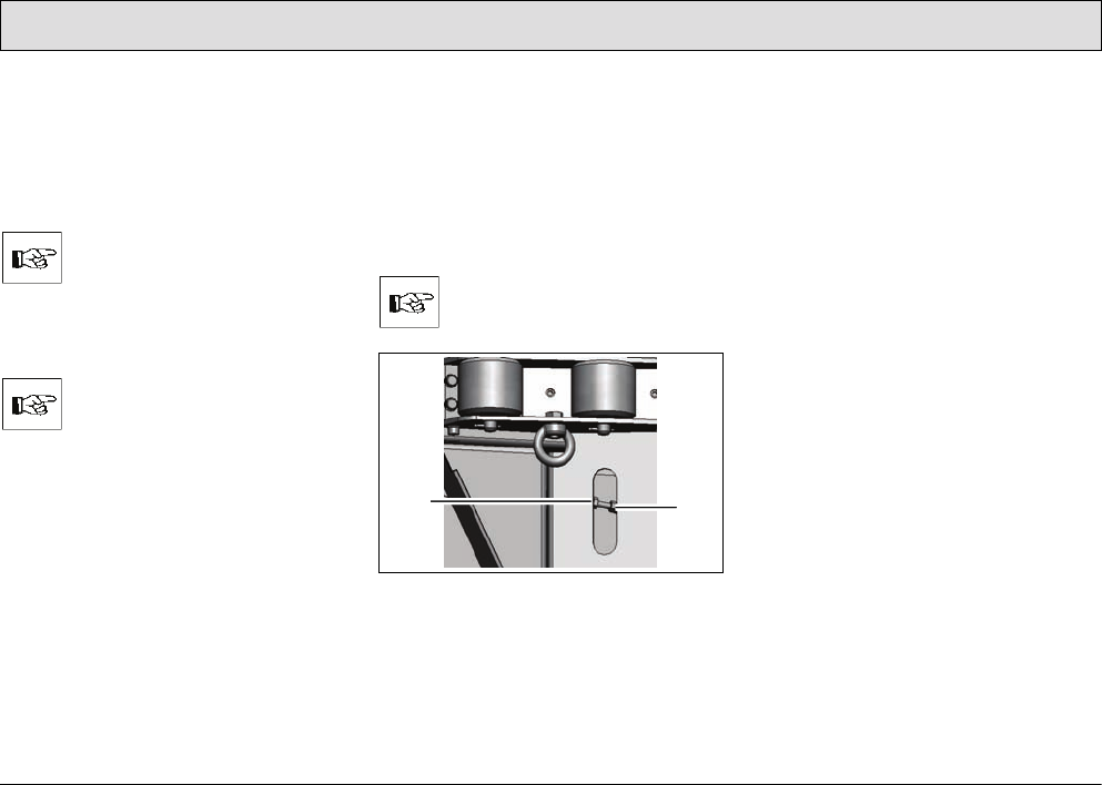
108
Maintenance and Service
Sweeping pattern is correct:
If the cylindrical brush is setup correctly,
the swept area on the floor forms a
rectangle whose side edges are
parallel. The short sides of the
rectangle should measure 1.2-2.0 in.
If the sweeping pattern is
broader than 2.0 in, the brush
pressure is too high. If the
sweeping pattern is narrower
than 1.2 in, the brush pressure
is too low.
The shape of the sweeping
pattern must be a rectangle
and not trapeze or wedge
shaped!
If the sweeping pattern is not correct, it
must be adjusted; refer to paragraph
”Setting the sweeping pattern”.
Setting the sweeping pattern
The adjusting devices for the sweeping
pattern can be accessed through the
openings in the side collision protection
on both sides of the vehicle.
1. Sit on the driver's seat, insert the key
in the key switch and turn to
position 1.
2. Press the “Button to switch the pre-
sweep/vacuum unit on and off”
(Fig. 22/4) to lower the side brush
and cylindrical brush.
3. Turn the key switch to position 0 and
remove the key. The cylindrical
brush and side brush remain
lowered.
All the adjustments must be
made on both sides of the
vehicle!
Fig. 40
1 Adjusting device for sweeping pat-
tern
2Counternut
4. Loosen the counternuts (Fig. 40/2)
on both sides of the vehicle.
5. Turn the adjusting device (Fig. 40/1)
on both sides of the vehicle as
described below:
- To make the sweeping pattern
broader, turn counterclockwise.
- To make the sweeping pattern
narrower, turn clockwise.
6. Check the sweeping pattern, refer to
paragraph ”Checking the sweeping
pattern”.
7. Repeat steps 1 to 7 until the
sweeping pattern is set correctly.
8. Tighten the counternuts (Fig. 40/2)
on both sides of the vehicle.
12
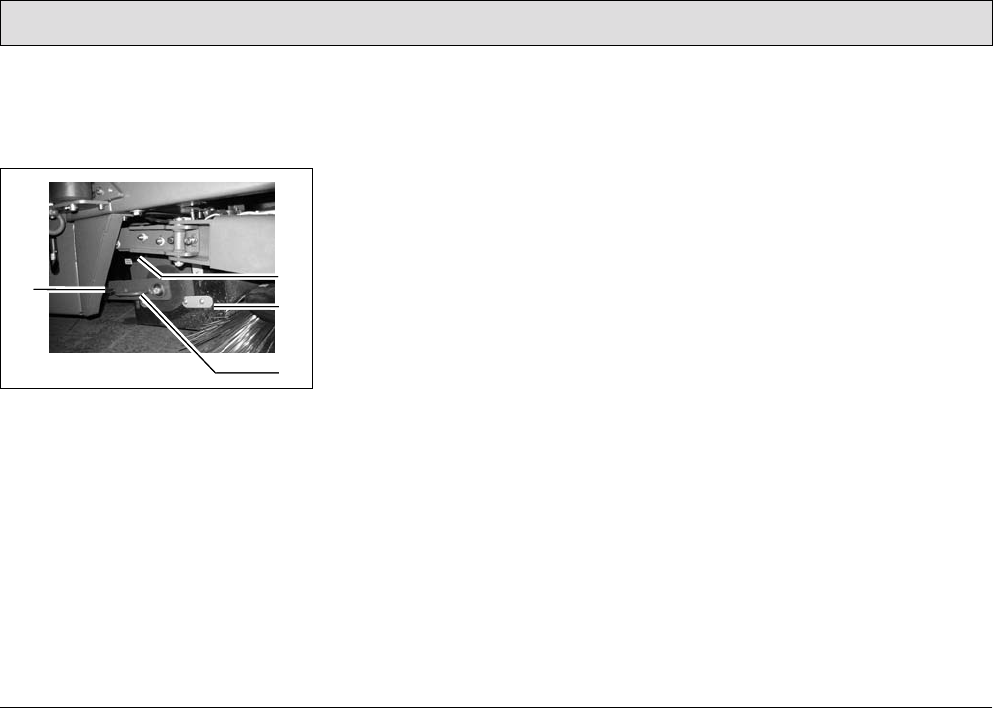
109
Maintenance and Service
Disassembling the cylindrical brush
The cylindrical brush can only be
accessed from the right-hand side of
the vehicle.
Fig. 41
1 Knurled screw for brush swing arm
2 Knurled screw for
brush space cover
3 Brush space cover
4 Brush swing arm
1. Sit on the driver's seat, insert the key
in the key switch and turn to
position 1.
2. Press the “Button to switch the pre-
sweep/vacuum unit on and off”
(Fig. 22/4) to lower the side brush
and cylindrical brush.
3. Turn the key switch to position 0 and
remove the key. The cylindrical
brush and side brush remain
lowered.
4. Unscrew the knurled screw for the
brush swing arm (Fig. 41/1).
5. Pull off the brush swing arm
(Fig. 41/4).
6. Unscrew the knurled screw for the
brush space cover (Fig. 41/2).
7. Remove the brush space cover
(Fig. 41/3).
8. Pull the cylindrical brush out.
Installing the cylindrical brush
The cylindrical brush must be installed
in the reverse sequence to
disassembly, refer to paragraph
”Disassembling the cylindrical brush”.
2
3
1
4
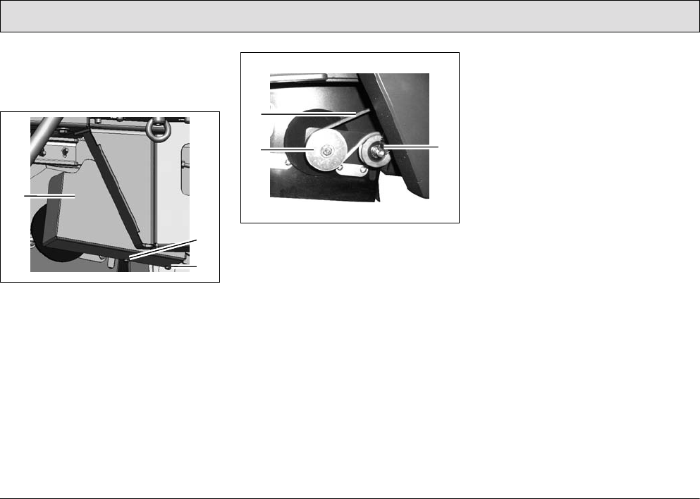
110
Maintenance and Service
Changing the belt for the cylindrical
brush
The cylindrical brush is driven by a belt
on the left-hand side.
Fig. 42
The cover (Fig. 42/1) of the belt is fixed
by two screws (Fig. 42/2).
1. Remove the screws (Fig. 42/2).
2. Remove the belt cover (Fig. 42/1).
Fig. 43
3. Remove the belt (Fig. 43/1) from the
pulleys (Fig. 43/2+3).
4. Place a new belt in position.
5. Assemble the belt cover (Fig. 42/1)
and fix with the screws (Fig. 42/2).
The belt tension is set by means of a
spring mounted tension pulley
(Fig. 43/3).
1
2
2
1
3
2
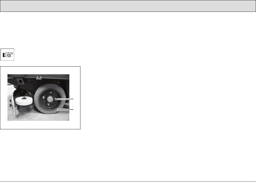
111
Maintenance and Service
5.10 Wheels
The wheel nuts on the wheels
(Fig. 44/1) must be subjected to their
first check after 100 operating hours
and subsequently every 200 hours.
The tightening torque for the
wheel nuts (Fig. 44/1) is
103.3 lb ft.
Fig. 44
5.10.1 Changing the rear wheels
1. Jack up the scrubber-drier on the left
or right side: The contact points for
the jack (lifting power: 2.0 t) are on
the frame in front of the rear wheels.
2. Remove the wheel nuts (Fig. 44/1).
3. Pull off the wheel (Fig. 44/2).
4. Fit a wheel (Fig. 44/2).
5. Screw on and tighten the wheel nuts
(Fig. 44/1).
5.10.2 Changing the front wheel
The procedure to change the front
wheel is analog to changing the rear
wheels:
1. Apply the jack at the front centered to
the vehicle's front frame and jack up
the scrubber-drier.
2. Unscrew the wheel nuts.
3. Remove the wheel.
4. Install the wheel in place.
5. Screw on and tighten the wheel nuts.
1
2
112
Maintenance and Service
5.11 Electrical installation
5.11.1 Red control lamps
Refer to Section 3.2.2.
5.11.2 Error codes
Refer to Sections 3.5.1 and 3.2.2.
5.11.3 Fuses
The fuses are located in the electronic
system underneath the seat console.
Take hold of the seat console by the
handle and pivot it up.
Always disconnect the battery
plug before starting any work
on the electrical installations.
All the stroke elements, all brush
motors for the scrubber-drier and all
motors for the side brushes and
cylindrical brush of the pre-
sweep/vacuum unit are equipped with
safety fuses and electronic fuses.
Safety fuses are installed in:
• the main fuse
(200A high current fuse (F50))
• the DC-DC converter
(10A plug-in fuse (A8))
When these fuses blow, the
vehicle is out of operation. This
is not indicated by an alarm
signal on the operating panel!
• the control unit (2A plug-in fuse (A1))
When these fuses blow, the
vehicle is out of operation. This
is not indicated by an alarm
signal on the operating panel!
• the suction turbines
(35A high current fuse)
• the water pump and relief valve for
the water supply (10A plug-in fuse)
• the drive motor (160A current limiter
in the drive control)
• the extractor fan of the pre-
sweep/vacuum unit
(20A plug-in fuse)
• the agitating motor for the pre-
sweep/vacuum unit (20A plug-in
fuse) and
• the working lights and flashing
beacon, automatic filling device, key
switch and horn (10A plug-in fuse
(F51))
When these fuses blow, the
vehicle is out of operation. This
is not indicated by an alarm
signal on the operating panel!
5.11.4 Drive control relay
The drive control is located in the left -
hand part of the driver's cab underneath
the foot plate.
Always disconnect the battery
plug before starting any work
on the electrical installations.
1. Loosen the screws in the foot plate
and remove the foot plate.
2. Relay K3 (main contactor) is
mounted upstream from the drive
control.
3. Replace a defect relay with a new
one.
4. Replace the foot plate and fix by
means of the screws.

113
Maintenance and Service
5.12 Cleaning the vehicle
1. Clean the vehicle on a weekly basis,
refer to Section 5.3.1.
2. Park the vehicle in an appropriate
washing area.
Observe the applicable laws
and local regulations when
disposing of water containing
cleaning agents and dirt!
3. Switch the vehicle off and remove
the key.
4. The vehicle may only be cleaned
using a water hose (operating
pressure approx. 72.51 to 87.01 psi)
and only from top to bottom.
It is not permitted to clean the
vehicle with a pressure washer
or steam blaster.
5. Do not aim the jet of water directly at
openings, slits, electronic
components, operating panels or
seals.
6. It is not permitted to use aggressive
and corrosive cleaning agents.
7. Allow the vehicle to dry after
cleaning. It is preferable to allow the
vehicle to dry over a longer period of
time, e.g. the weekend.
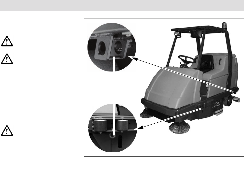
114
Maintenance and Service
5.13 Transport and towing
Loading
Observe the operating
information on transportation!
Check the load bearing
capacity of the loading platform
prior to loading.
• Dead weight of the scrubber-drier
without battery, without options and
without driver: 2061 lbs
• Total weight of the scrubber-drier
with battery and full fresh water tank,
without driver: 3549 lbs
• When loading onto a truck or
something similar by means of a
loading ramp, the ramp angle must
not exceed 15%.
The climbing capacities
stipulated in this manual can
and may only be achieved with
the battery specified in the
Section „Technical Data“.
Fig. 45
1
2

115
Maintenance and Service
• Squeegee, brush head and side
brush and cylindrical brush of the
pre-sweep/vacuum unit must be
raised.
If the side brush collision protection
option is assembled, it must be
disassembled.
Transport
• When driving the vehicle (transport
mode) to the site of use, the
squeegee, scrubbing unit and side
brushes and cylindrical brush on the
pre-sweep/vacuum unit must be
raised.
• When the vehicle is to be
transported on another vehicle or
trailer, it must be secured against
rolling away. Lash the vehicle down
securely. The vehicle is provided
with attachment points (lashing
eyes) on the left and right-hand side
to do this: at the rear of the frame
and on the sides at the height of the
entry area (Fig. 45/1+2).
Towing the vehicle
If it should become necessary to tow
the scrubber-drier, only do it on level
ground and at a maximum towing
speed of 2.5 mph. The tow rope must
be attached at the front lashing points.


Excellence Meets Clean
PowerBoss Inc. · 175 Anderson Street · Aberdeen, NC 28315 U.S.A.
Telephone: (910) 944-2105 · Fax: (910) 944-7409
88-10-2987 Rev * 07/13
