B5 / B7 SpeedGleam 5 7 Service Manual Tennant Walk Behind Floor Burnisher
2018-06-20
: Sweepscrub Tennant-B5-B7-Walk-Behind-Floor-Burnisher-Service-Manual tennant-b5-b7-walk-behind-floor-burnisher-service-manual 2780 file product_file
Open the PDF directly: View PDF ![]() .
.
Page Count: 64
B5/B7
SpeedGleam® 5
SpeedGleam® 7
9011478
Rev. 00 (01-2014)
www.tennantco.com
www.nobles.com
Walk-Behind Battery Burnisher
North America / International
Service Information Manual
TennantTr u e® Parts
*9011478*
INTRODUCTION
This manualprovides necessary service and
maintenance instructions.
Read thismanual completely and
understand the machine before
servicing it.
This machinewill provide excellent service. However,
the best results will be obtained at minimum costs if:
SThe machine is operated with reasonable care.
SThe machine is maintained regularly-per the
maintenance instructions provided.
SThe machine is maintainedwith manufacturer
supplied or equivalentparts.
To view, print or download manualsonline visit
www.tennantco.com/manuals
PROTECT THE ENVIRONMENT
Please dispose of packaging materials
and used machine components such
as batteries in an environmentally safe
way according to yourlocal waste
disposal regulations.
Always remember to recycle.
Tennant Company
PO Box 1452
Minneapolis, MN 55440
Phone: (800)553- 8033 or (763)513- 2850
www.tennantco.com
www.nobles.com
Trojan and HydroLINK are registered trademarks of Trojan Battery Company.
Specificationsandparts are subject to change withoutnotice.
OriginalInstructions. CopyrightE2014 Tennant Company.
All rights reserved. Printed in U.S.A.
INTENDED USE
The burnisher machine is intended for commercial use,
for example in hotels, schools, hospitals, factories,
shops, offices and rental businesses. It is designed to
burnish smooth dry hard floor surfaces (VCT, terrazzo,
marble, finishedhardwood, coated concrete, etc.) in an
indoorenvironmentonly. Do not use this machine on
carpeted surfaces. Use only recommendedburnishing
padsintended for machineapplication.Do not use this
machine other thandescribed in this Operator Manual.
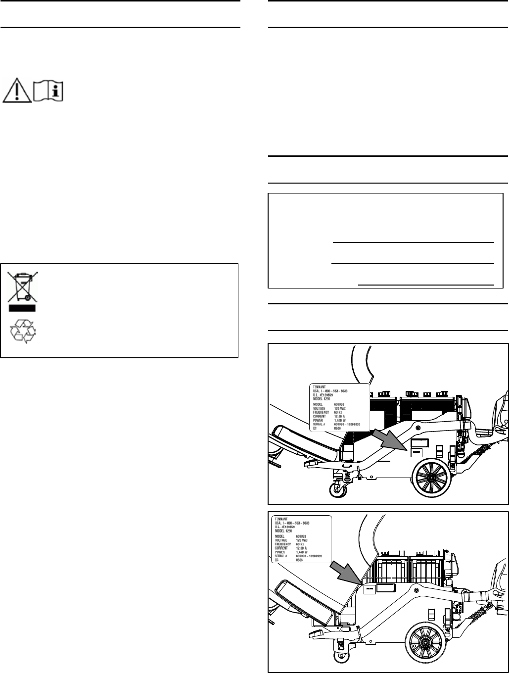
MACHINE DATA
SERIAL NUMBER LABEL LOCATIONS
B7
SpeedGleam 7
B5
SpeedGleam 5
Please fillout at time of installation
for future reference.
ModelNo. -
SerialNo. -
InstallationDate -

B5/7, SpeedGleam® 5/7 Service Information (1-14) 3
CONTENTS
Safety PrecautionS ........................11
General information .....................21
COMPONENT LOCATOR .................... 22
ELECTRICAL SCHEMATIC, SYMBOLS ........ 23
ELECTRICAL SCHEMATIC
DRIVE MODEL ......................24
ELECTRICAL SCHEMATIC
PUSH MODEL ...................... 26
OPERATIONAL MATRIX .....................28
SPECIFICATIONS ...........................29
FASTENER TORQUE ..................... 29
GENERAL MACHINE DIMENSIONS/
CAPACITIES/PERFORMANCE ........210
MACHINE DIMENSIONS ................213
maintenance
MAINTENANCE CHART .....................32
AFTER DAILY USE .......................33
AFTER WEEKLY USE .....................33
AFTER EVERY 50 HOURS OF USE ........ 34
AFTER EVERY 100 HOURS OF USE .......34
AFTER EVERY 200 HOURS OF USE .......34
AFTER EVERY 1000 HOURS OF USE ...... 35
BATTERY MAINTENANCE ..................35
SEALED/AGM BATTERIES ............... 35
WET/LEADACID BATTERIES ............ 35
HYDROLINK™ BATTERY WATERING
SYSTEM OPTION ................... 36
MACHINE JACKING ........................ 37
PUSHING TOWING AND TRANSPORTING
THE MACHINE .......................... 37
STORING MACHINE ........................ 38
troubleShootinG
BDI FAULTS ................................42
SUBSYSTEM TROUBLESHOOTING .......... 44
BURNISH MOTOR .......................44
BATTERY CHARGER ON BOARD ........46
BATTERY CHARGER OFF BOARD .......48
POWERUP CIRCUIT ....................410
PROPEL OPTION .....................412
BURNISH HEAD
LIFT ACTUATOR OPTION ........... 414
VACUUM FAN OPTION ................416
Service
SOFTWARE CONFIGURATION TOOL ........ 52
CONNECTING TO THE INTERFACE
MODULE ............................ 52
MACHINE CONFIGURATION
SOFTWARE .......................... 53
BATTERY CHARGER SETTING ............... 54
PAD PRESSURE SETTING ................... 55
Contents Page
BURNISH MOTOR .......................... 56
VACUUM FAN .............................. 58
CONTROL MODULES .......................59
ONBOARD BATTERY CHARGER ............511
INTERFACE MODULE ......................512
BAIL SWITCH OR POTENTIOMETER ........513
Contents Page

CONTENTS
4B5/7, SpeedGleam® 5/7 Service Information (1-14)

B5/7, SpeedGleam® 5/7 Service Information (1-14) 1-1
SAFETY PRECAUTIONS
IMPORTANTSAFETY INSTRUCTIONS - SAVE THESEINSTRUCTIONS
The followingwarning precautions are used throughout
this manual as indicated in theirdescription:
WARNING: To warn of hazards or unsafe
practiceswhich couldresult in severe personal
injury or death.
FOR SAFETY: To identify actionswhich must be
followed for safe operation of equipment.
The followinginformation signalspotentially
dangerous conditions to the operator. Knowwhen
these conditions can exist. Locate all safety devices on
the machine.Report machinedamage or faulty
operation immediately.
WARNING: To Reduce the Risk of Fire,
Explosion, Electric Shock or Injury:
- Readmanual before operatingmachine.
- Do not use or pick up flammablematerials.
- Do not use near flammableliquids, vapors or
combustibledusts.
Thismachineisnot equipped with an
explosion proof motor. The electric motor will
sparkupon start up and duringoperation
which couldcauseaflash fire or explosion if
machine is usedinanareawhere flammable
vapors/liquids or combustibledusts are
present.
-Batteries emit hydrogen gas. Explosion or fire
canresult. Keep sparks and open flame away
when charging.
- Disconnect batterycables and charger cord
before cleaning and servicingmachine.
- Do not charge batteries with damaged cord. Do
not modify plug.
If the charger supply cord is damaged or
broken, it must be replaced by the
manufacturer or its service agent orasimilarly
qualified person in order to avoid a hazard.
The use of incompatible battery chargersmay
damage the battery and potentiallycauseafire
hazard.
- Do not use outdoors or on wet surfaces. Store
indoors.Thismachine is for dry use only.
-Thismachineisnot suitable for picking up
hazardousdust.
- Spinning pad, keep hands away.
FOR SAFETY:
1. Do notoperate machine:
- Unless trained and authorized.
- Unlessoperator manual is read and
understood.
- Unlessmentally and physicallycapable of
followingmachineinstructions.
- Under the influence of alcohol or drugs.
-While using a cell phone or other types of
electronic devices.
- If not in proper operating condition.
- In outdoor areas.Thismachine is for
indoor use only.
-With pads or accessories not supplied or
approved by Tennant. The use of other
pads may impair safety.
- In areaswith possible fallingobjects.
- In areas that are too dark to safely see the
controlsoroperate machine.
-Withoutdust bag and filters in place.
2. Before operatingmachine:
- Make sure all safety devicesare in place
and operate properly.
3. When operatingmachine:
-Useonly as described in thismanual.
-Report machine damage or faulty operation
immediately.
- Wear closed- toe, non- slipwork shoes.
-Reduce speedwhen turning.
-Keep hands away from spinning pad.
- Go slowly on inclines and slippery
surfaces.
- Do notburnish on inclines that 9% grade or
transport on inclines that exceed19.5%
grade.
- Do notcarry passengers on machine.
-Usecarewhen reversingmachine.
-Keep children and unauthorized persons
away from machine.
- Do not allow to be used asatoy.

1-2 B5/7, SpeedGleam® 5/7 Service Information (1-14)
SAFETY PRECAUTIONS
4. Before leaving or servicingmachine:
- Stop on level surface.
- Set the parking brake, if equipped.
- Turn off machine and remove key.
5. When servicingmachine:
- Disconnect battery connection and charger
cord before working on machine.
- All work must be donewith sufficient
lighting and visibility.
- All repairs must be performed by trained
personnel.
-Use Tennant supplied or approved
replacement parts.
- Do not modify the machine from its original
design.
- Avoid moving parts. Do not wearloose
clothing or jewelry and secure long hair.
- Do notdisconnect the off- board charger’s
DC cord from the machine’s receptacle
when the charger is operating.Arcingmay
result. If the charger must be interrupted
during charging,disconnect the AC power
supply cord first.
- Do not use incompatible battery chargers
as thismay damage battery packs and
potentiallycauseafire hazard.
-Inspect charger cord regularly for damage.
-Keepwork area well ventilated.
- Avoid contactwith batteryacid.
-Keep all metal objects off batteries.
- Do notpower sprayorhose off machine.
-Use a hoist or adequate assistance when
lifting batteries.
-Jackmachine up at designated locations
only. Support machinewith jack stands.
- Block machine tires before jackingmachine
up.
- Useahoist or jack that will support the
weight of the machine.
- Wear personal protection equipment as
needed and whererecommended in this
manual.
For Safety: wear protective gloves.
For Safety: weareye protection.
For Safety: wear protective dust mask.
6. When loading/unloadingmachineonto/off
truck or trailer:
-Usearamp that can support the machine
weight and operator.
- Do notoperate the machine on a ramp
incline that exceedsa19.5% grade level.
-Useawinch if rampinclineexceeds a
19.5% grade level.
-Lower the pad driver after loading.
- Turn machine off and remove key.
- Set parking brake (if equipped).
- Block machinewheels.
-Use tie- down straps to secure machine.
B5/7, SpeedGleam® 5/7 Service Information (1-14) 1-3
SAFETY PRECAUTIONS
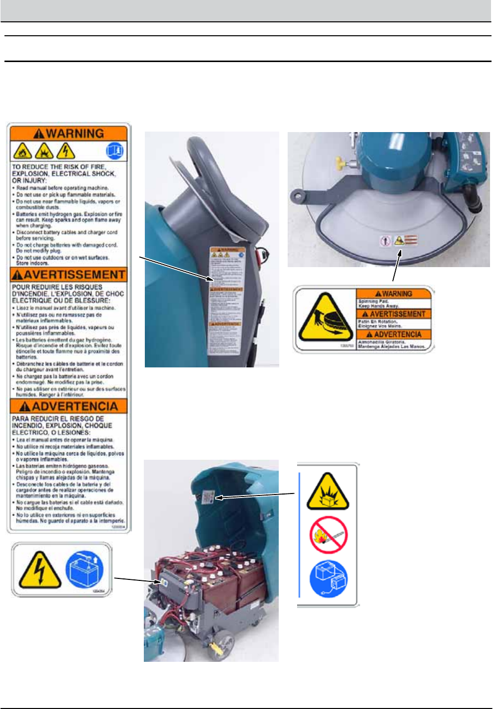
SAFETY LABELS
The safety labelsappear on the machine in the locationsindicated.Replace labels if they are missing or become
damaged or illegible.
WARNING LABEL - Located on side of control console.
WARNING LABEL -
Disconnect battery
cables before servicing
machine.
Located on control board
cover.
WARNING LABEL -
Batteries emit
hydrogen gas.
Explosion or fire
canresult. Keep
sparks and open
flame away when
charging.
Located on backside
of machine cover.
WARNING LABEL -
Spinning Pad. KeepHands Away.
Located on burnishinghead.

1-4 B5/7, SpeedGleam® 5/7 Service Information (1-14)
SAFETY PRECAUTIONS

GENERAL INFORMATION .....................21
COMPONENT LOCATOR .................... 22
ELECTRICAL SCHEMATIC, SYMBOLS ........ 23
ELECTRICAL SCHEMATIC
DRIVE MODEL ......................24
ELECTRICAL SCHEMATIC
PUSH MODEL ...................... 26
OPERATIONAL MATRIX .....................28
SPECIFICATIONS ...........................29
FASTENER TORQUE ..................... 29
GENERAL MACHINE DIMENSIONS/
CAPACITIES/PERFORMANCE ........210
MACHINE DIMENSIONS ................213
GENERAL INFORMATION
SECTION 2
Contents Page
2-1
B5/7, SpeedGleam® 5/7 Service Information (1-14)
2-2 B5/7, SpeedGleam® 5/7 Service Information (1-14)
GENERAL INFORMATION
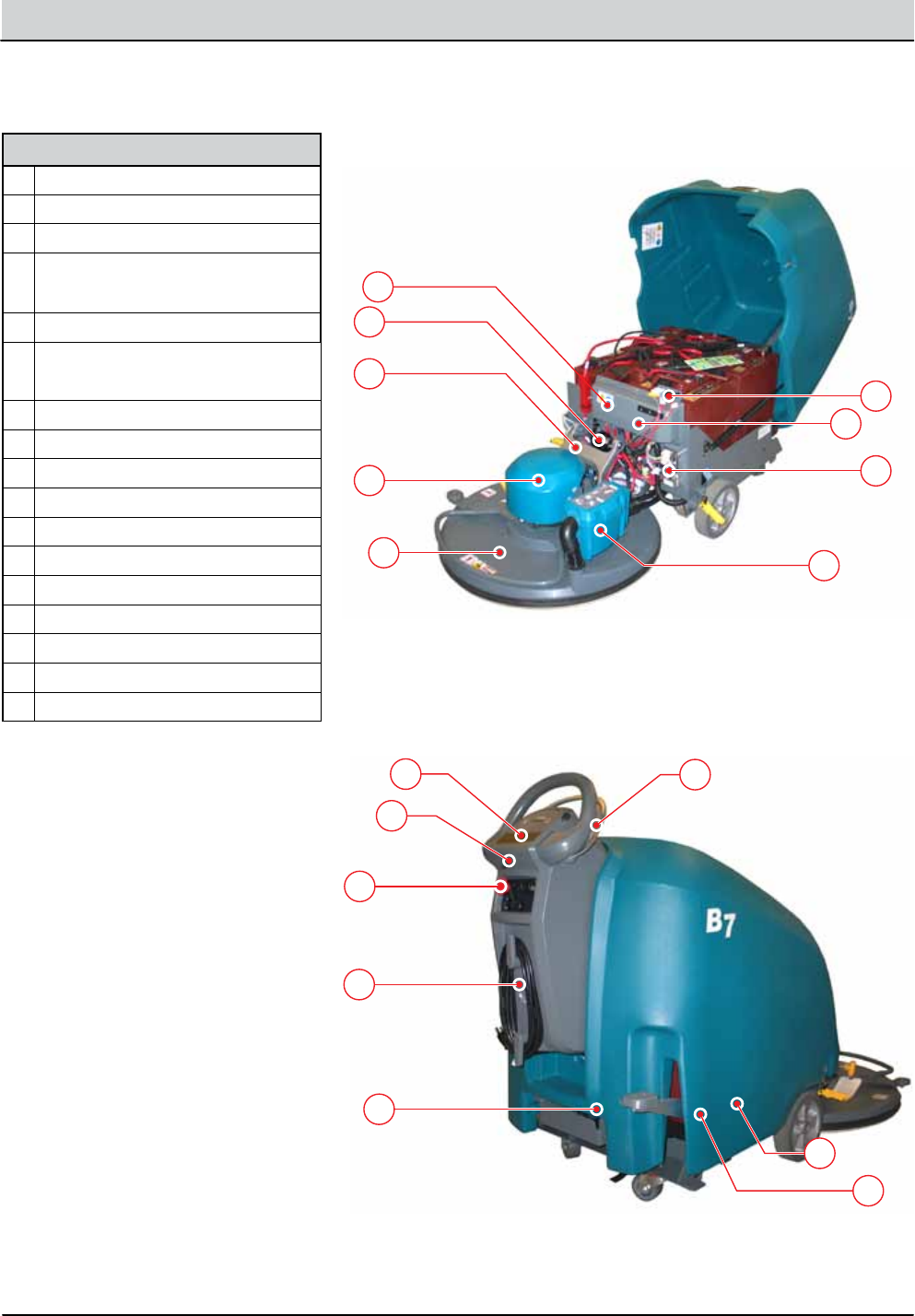
COMPONENT LOCATOR B7 SHOWN
I
A
H
F
E
G
B
C
D
L
K
N
M
O
J
P
Q
Components
AHalf-Bridge Control Module
BCircuit Breakers
CBase Control Module
DI-Drive Control Module
(B/SG5*)
EDust bag and HEPA panel lter
FBurnish Head - 20", 24", 27"
(B7, 27" shown)
GBurnish Motor
HContact Switch, Pad Up/Down
IHead Lift Actuator*
JE-Stop Switch*
KUSB Programming Port
LInterface Control Module
MBurnish/Propel* Activation Bail
NPropel Transaxle*
OVacuum Fan*
PCover Contact Switch
QOnboard Battery Charger*
* Optional Equipment

B5/7, SpeedGleam® 5/7 Service Information (1-14) 2-3
GENERAL INFORMATION
ELECTRICAL SCHEMATIC SYMBOLS
1
2
2
1
+ -
+ -
Switched B+
From Buss Bar
Switched B+
B- From
Stando
B- From
Stando
S-5 Seat Switch (N.O.)
Amer
Encoder
Cable
C1 Capacitor (0.01Uf)
R1
(11 Ω/40W)
+ -
MTR
ecH2O
Pump
J3-2 Brush RT-
J3-5 Brush LT+
J3-6 Brush LT-
Right/Rear Brush
Left/Front* Brush
* Cylindrical = Uses Adaptor
ecH2O
Control
Module
T16
Control
Board
VCC_A
Alarm
Com N.C.
N.O.
S-14 Pressure Sw.
N.C. Opens @ 25 +/- 2 psi
Enable
GND_A
GND_B
Pressure IN
(ECH2O SW)
(ECH2O SW)
VCC_B
VCC_C
Pump
(SOL-A)
ecH2O Valve
Sparger
e-Cell
65EA/BLU
5EA/GRN
8EA/GRY
7EA/PUR
3EA/ORA
4EA/YEL
(SOL-B)
(SPA-A)
(SPA-B)
(CELL-A)
(CELL-B)
(LED GND)
(LED RED)
(LED GRN)
Squeegee
Actuator
Battery Positive +
Battery Negative -
D-8
FU2
100A
70/TAN
M4A
86 85
B+
J7-1 B+ Control
B-
Cable
8/GRY
FU1
100A
FU1
100A
102/BRN
Sweep OFF/Down = 2-1, 6-5
Sweep ON/Center = 2-3, 6-7
Vac & Sweep ON/Up = 3-4, 7-8
Cable
Pre-Sweep
Brush Relay
CB3 (2.5A)
CB19 (25A)
CB16 (15A)
J7-4 Sweep
Note:
ecH2O Enable:
J7-10 Low=Turn ON ecH2O
Note:
Pre-Sweep Enable:
J6-10 B+ = Sweep Enable ON
Sweep Enable J6-10
37/PUR
38/GRY
CB9 (2.5A) 79/WHT
CB10 (2.5A)
Note:
ecH2O Side Brush
J7-12 Low=SV3 H20 Valve ON
ecH2O Pump ON 100%
13/BLK
88/GRY
9EA/WHT
S-15
Flush Switch
13EA/BLK
21/PNK
Extend
Limit Sw.
22/BRN
MTR 26/BLU
25/GRN
2/BRN
Switched B+
From Buss Bar
Switched B+
From Buss Bar
Switched B+
To: CAN Open-
(J6-14)
To: Throttle
Sensor (GND)
To: Curtis 1234
(I/O GND)
To: CAN Open+
(J6-13)
To: Back-Up
Light Circuit
To: Back-Up
Alarm Circuit
80/TAN
PMC001
12
12
MTR
10 4
1
3
2
7
9
6-4
6-8
5
6
11
12
8
6-1
6-2
6-3
6-6
6-5
6-7
ON
OFF
6
2
8
5
4
1
FWD
REV
6
2
8
BA
5
4 J1-33
GND Cable
J1-34
J1-21
W/WHT
V/GRN
U/ORN
J1-3
J1-4
J1-13
J1-11
BLU2 J1-32
J1-26
J1-31
J1-7
J1-18
J1-15
66/BLU
61/PNK
62/BRN
12/BRN
17/PUR
Propel Motor Assembly
17/PUR
15/GRN
87/PUR
Temp Sender
Brake
Solenoid
59/WHT
58GRY
RED1
WHT5
BLK6
YEL
T2
B1 B2
T1
YEL
J1-16
J1-35
J1-23
P1-C
BLU
YEL
P1-B
P1-D
BLK
P1-A
RED
J1-22
J1-9
J1-1
B+
J1-29
J1-28
J1-25
1
1
3
5
7
2
4
6
8
Pre-Sweep Switch
Sweep OFF/Down = 2-1, 6-5
Sweep ON/Center = 2-3, 6-7
Vac & Sweep ON/Up = 3-4, 7-8
1
3
5
7
2
4
6
8
M3B
MTR
MTR
MTR
MTR
FaST/ES Pump
D-9
D-6
D-7
D-12
67/PUR
64/YEL 81/PNK
Pre-Sweep
Vacuum Fan
LH Side Broom Motor
Main Broom Motor
13/BLK
13/BLK
65/GRN
65/GRN
65/GRN
68/GRY
69/WHT
D-11
30 87
M3A
Curtis 1234
Controller
PROG +
TX
RX
B+
KSI
INTERLOCK
FWD
FWD/REV Switch
Throttle Sensor
REV
B -
GND
B+
THROTTLE
BRAKE
CAN TERM L
CAN TERM H
U
DRV3
DRV4
DRV1
THERMISTOR
I/O GND
PHASE A
PHASE B
+5V
DRV2
COIL RETURN
V
W
BRAKE IN
(0-5 vdc)
(0-5 vdc) THROTTLE
CAN L
8/GRY 8/GRY
18/GRY
16/BLU
94/YEL
9/WHT
11/PNK
14/YEL
58/GRY
58/GRY
CAN H
6 Volt
IGN
15
ACC
30
BAT T
75
50 Start
ST
To: Back-Up
Alarm Circuit
+ -
Com N.C.
N.O.
1
3
5
7
2
4
6
8
MTR MTR
M3B
30 87
M3B
30 87a
M3A
IGN ST
+ -
Note: Key Switch ON
Key Switch
Battery
DPDT Switch
Pressure Switch
Motor
3 Phase AC
Induction Motor
Motor Encoder
Momenary Switch N.O.
Contact Switch N.C.
Solenoid Valve
Sensor
(Variable Resistor)
Circuit Breaker
Fuse
Diode
Single Continuation Tab
Double Continuation Tab
Relay Coil
N.C. Relay Contacts
N.O. Relay Contacts
Horn or Alarm
Light
Connected
Not Connected
Connector
Energized
Adaptor Harness
Notes
Assembly
AC Plug
Capacitor
Electro-
Magnetic
Brake
Enabled (Applied)
• Key O
• Neutral - Ready State
• Brake Command
• Seat Switch Open
• Curtis 1234 Fault
(See Troubleshooting)
• Throttle Command
• Seat Switch Closed
Disabled (Released)
Operational Matrix:
Propel
Enabled
• Seat Switch Closed
• Foot Throttle
Command
• Fwd/Rev Switch Input
• Seat Switch Open
• Neutral-Ready State
• Brake Command
• Curtis 1234 Fault
Disabled
Operational Matrix:
* SV2 Water Valve Voltage
Range
Low 1-LED
2-LEDs
3-LEDs
1-LED
2-LEDs
3-LEDs
1-LED
2-LEDs
3-LEDs
20%
30%
45%
30%
55%
80%
55%
80%
100%
7.2 Volts
10.8 Volts
16.2 Volts
10.8 Volts
19.8 Volts
28.8 Volts
19.8 Volts
28.8 Volts
36 Volts
Med
(Default)
High
Level PWM% @ Nominal
36 VDC
2-4 B5/7, SpeedGleam® 5/7 Service Information (1-14)
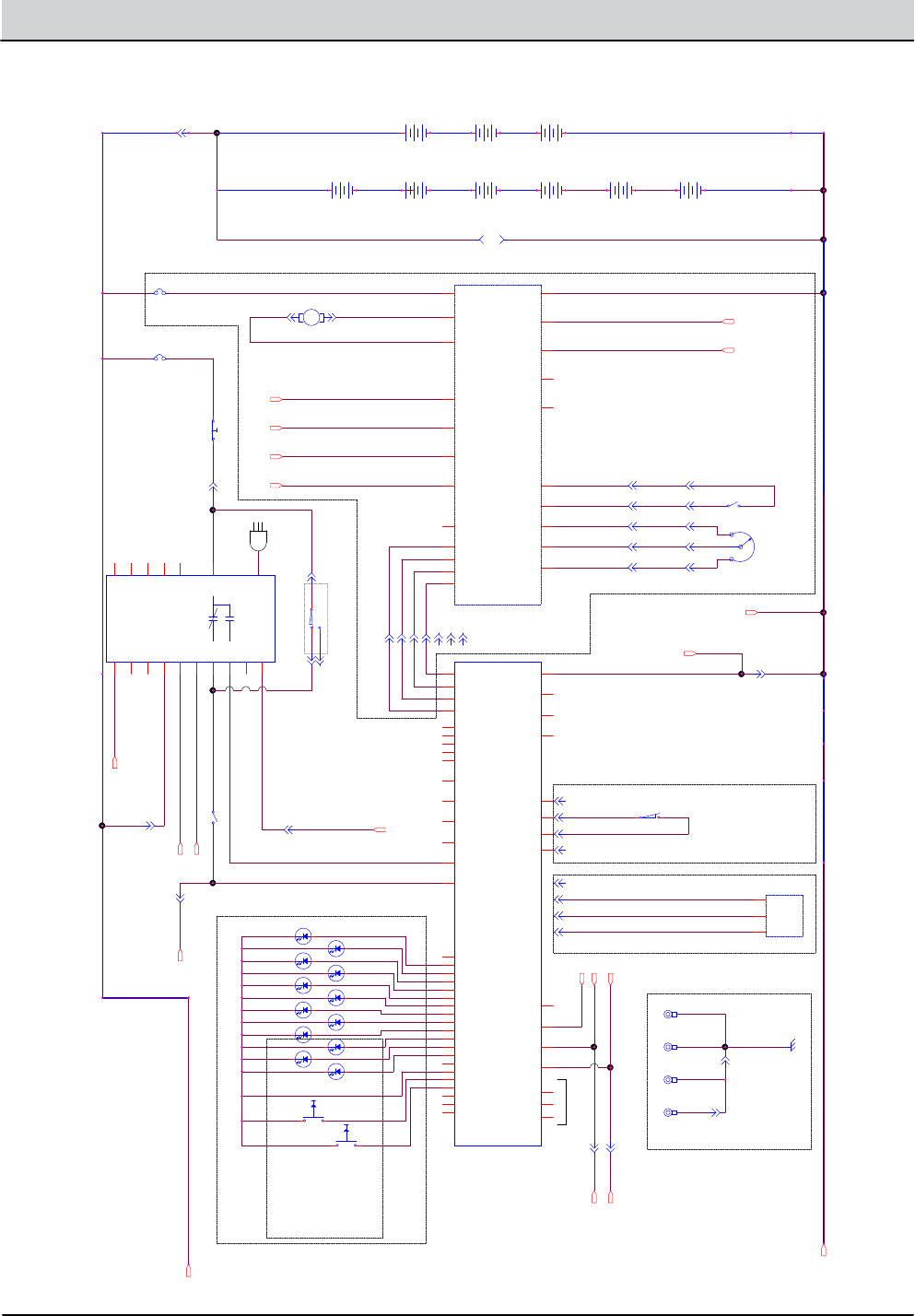
GENERAL INFORMATION
ELECTRICAL SCHEMATIC (DRIVE MODEL) - 1 of 2
B5/SpeedGleam5 (3 x 12 vDC)
B7/SpeedGleam7 (6 x 6 vDC)
36 VOLT CONFIGURATIONS
PROPEL
MODULE
(OPTIONAL)
CAN BUS
SW-9:
HOOD DISABLE SWITCH
(OPEN = HOOD UP = MACHINE OFF)
SW-2
13
OFF BOARD CHARGER CABLE (OPTION)
SW-1 = CHARGER INTERLOCK SWITCH
OFF-BOARD CHARGER ONLY: SW.
N.O.
N.C.
COM
I-DRIVE STATUS
COMMUNICATION CABLE
(SHIELDED)
POWER ON/OFF
CIRCUITRY
B5 CABLE B+/FUSE ASSY
B7 CABLE B+/FUSE ASSY
GROUND
B+
SWITCHED, B+
OPERATOR'S SWITCH/LIGHT PANEL
I-DRIVE PROPEL SYSTEM
OPTIONAL ON B5/SpeedGleam 5
STANDARD ON B7/SpeedGleam 7
CABLE, CHARGER
BDI_0
BDI_1
BDI_2
BDI_3
BDI_4
MTR HOT
SERVICE
DB FULL
IRIS
DP LOW
DP MED
DP HIGH
GROUND
INCREASE
DECREASE
REVERSE SWITCH
(GND. = REV.)
SW-4
ENABLE I-DRIVE
(B+ = ON)
FOOTPEDAL / PAD CHANGE
I-DRIVE SUPPLY VOLTAGE DETECT
AC PLUG
KEY SWITCH
J1-9
J1-8
J1-7
J1-6
J1-10
J1-11
J1-12
J1-5
J1-4
J1-3
J1-2
J1-1
J2-8
J2-2
J2-1
J10-1
J10-2
J10-3
J11-1
J11-2
BAIL SWITCH INPUT @ J4-4: 0V OR 5V
0V = NEUTRAL / BURNISH MTR OFF.
5V = MAX. PROPEL / BURNISH MTR ON.
BAIL SWITCH (N.O.)
SW-5:
NO CONNECTION
SENSOR OUTPUT: 0.5 TO 4.5VDC.
0.5V = NEUTRAL
4.5V = MAX. PROPEL
SENSOR REPL. SW-5.
J4-4
J4-1
J4-3
OPT: BAIL POSITION SENSOR ASSY
LED1
LED2
LED3
LED4
LED5
LED7
LED6
LED8
LED9
LED10
LED11
LED12
SW2
SW1
OPT: Active Down Pressure
NOTE: The Active Down Pressure
buttons and LEDs exist on all
machines, but are only visible on
models equipped with automated
down pressure. On models
equipped with mechanical “Set and
Forget™” down pressure, the LH (SW1)
button is used to enter pressure
adjust mode. Refer to the operator’s
manual for more information.
OPT: BAIL SW. HARNESS
I-DRIVE_AUX2
I-DRIVE_AUX3
CAN GROUND
NO CONNECTION
J4-2
NO CONNECTION
J2-4
J2-3
CAN BUS
RS232 DEBUG
PORT
CAN BUS
STATIC GROUNDING
(PART OF MAIN HARNESS
AND OP.STATION HARNESS)
CABLE, CHARGER
CABLE, CHARGER
1/RED
BLK
1/RED
13/BLK1/RED
9/WHT
10/TAN
13/BLK 13/BLK1/RED YRG/8YRG/8
NRB/21NRB/21
34/YEL
35/GRN
33/ORA
CABLE: RED
CABLE: BLACK
1/RED
3/ORA
RED
CABLE: NATURAL
7/PUR
6/BLU
4/YEL
35/GRN
34/YEL
33/ORA
SHIELD/GRN
CABLE:NATURAL
CABLE: RED
CABLE: BLACK
SHIELD/GRN
37/PUR
36/BLU
37/PUR
36/BLU
24/YEL
27/PUR
KNP/11KNP/11
13/BLK
5/GRN
6/BLU
KLB/31KLB/31 13/BLK
13/BLK
GRN
GRN
GRN
WHT
WHT
BROWN (+5VDC)
BLACK (SENSOR OUTPUT)
BLU (GROUND)
CAN+ /YEL
CAN- /GRN
4/YEL
4/YEL
7/PUR
5/GRN
30/TAN
31/PNK
LEY/41LEY/41
ULB/62ULB/62
113/BLK/WHT
113/BLK/WHT
CAN- /GRN
CAN+ /YEL
105/GRN
105/GRN
105/GRN
105/GRN
105/GRN
13/BLK
TO: BATT. GROUND
13
1
6
24
27
CAN+
CAN-
13
113
113
CAN-
CAN+
CAN-
CAN+
13
SW-1
CHARGER: ON BOARD
NC
P2-2
GND
P1-B-
B+
P1-B+
COM
P2-3
CAN+
P2-6
CAN-
P2-10
NO
P2-4
CAN_GND
P2-1
SENSE+
P2-5
SENSE-
P2-14
RESERVED3
P2-11
LED+
P2-12
LED-
P2-13
RESERVED1
P2-8
RESERVED2
P2-9
RETURN
P2-7
OP.STATION
CB-1
2.5A
6 VDC
+ --
12 VDC
+ --
BURNISH HEAD
I-DRIVE
B+
P2-B+
ON/OFF
P1-5
M2
P2-M2
M1
P2-M1
GND_REF
P1-13
B-
P2-B-
AUX2_OUT
P1-3
FUSED, B+_OUT
P1-7
STATUS
P1-10
POT LOW
P1-8
REVERSE
P1-12
SPD LIMIT
P1-9
POT HIGH
P1-2
AUX3_OUT
P1-11
PROG_B+
P3-2
LOW SPEED
P1-4
DIGITAL_GND
P3-1
TX
P3-3
RX
P3-4
WIPER_IN
P1-1
OPEN_B
P1-6
OPEN_C
P1-14
VAC FAN
100K PROPEL SPEED LIMIT
POT.-1
1
2
3
6 VDC
+ --
6 VDC
+ --
CHASSIS GND. STRAP @ FRAME
INTERFACE MODULE
+5V OUT
J4-1
CAN-
J3-2
CAN+
J3-1
CHARGER INPUT
J7-9
KSI
J7-10
SENSE_GND
J4-3
COMM_GND
J5-1
TX
J5-3
RX
J5-4
V_BUS
J6-1
SHLD_GND
J3-3
N/C
J3-4
SENSOR_IN
J4-4
WIPER OUT
J5-2
GND
J7-8
COM_GND2
J2-3
TX_2
J2-1
RX_2
J2-2
+5VDC_OUT
J7-1
D-
J6-2
D+
J6-3
ID
J6-4
GND_SHIELD
J6-5
LSD_OUT_0
J7-5
LSD_OUT_1
J7-6
LSD_FLYBACK
J7-7
INPUT_0
J7-2
INPUT_1
J7-3
INPUT_2
J7-4
LED_+5VDC_OUT
J9-1
BDI_0_LED
J9-2
BDI_1_LED
J9-3
BDI_2_LED
J9-4
BDI_3_LED
J9-5
BDI_4_LED
J9-6
MTR_HOT_LED
J9-7
SERVICE_LED
J9-8
DB_FULL_LED
J9-9
IRIS_LED
J9-10
DP_1_LED
J9-11
DP_2_LED
J9-12
DP_3_LED
J9-13
SPARE_LED
J9-14
GND_1
J9-15
DP_INC_SW
J9-16
DP_DEC_SW
J9-17
SPARE_SW1
J9-18
SPARE_SW2
J9-19
GND_2
J9-20
NOT USED
J4-2
6 VDC
+ --
OPT: BAIL POS. SENSOR
GND
2
+5V
3
OUTPUT
1
MTR1
PROPEL MOTOR
2 1
6 VDC
+ --
12 VDC
+ --
KEY SWITCH
CB3
30A
6 VDC
+ --
12 VDC
+ --

B5/7, SpeedGleam® 5/7 Service Information (1-14) 2-5
GENERAL INFORMATION
ELECTRICAL SCHEMATIC (DRIVE MODEL) - 2 of 2
ENABLE I-DRIVE
CABLE MOTOR TO 1/2 BRIDGE PCB
J5 & J11 (EVEN PINS 2 THROUGH 20)
= GROUND.
GROUND
B+
SWITCHED, FUSED, B+
CAN+
CAN-
RIBBON CABLE ASSY.
I-DRIVE B+ DETECT
E-STOP SWITCH
INTERNAL TO BURNISH MOTOR
FOOTPEDAL / PAD CHANGE
FOOT PEDAL/PAD CHANGE SW.
(GND. = ENABLE BURNISH)
SW-7: N.O.H.C.
I-DRIVE STATUS
I-DRIVE_AUX3
I-DRIVE_AUX2
HOUR METER
5.0 AMPS
OPTIONAL: BURNISH HEAD ACTUATOR
1/2 BRIDGE
MODULE
BASE BURNISHER
MODULE
CABLE B+/FUSE ASSY
RS232 DEBUG
PORT
7-2J6-2J
J2-5
CABLE B+/FUSE ASSY
13/BLK13/BLK
24/YEL
CAN- /GRNCAN- /GRN
6/BLU 6/BLU6/BLU
1/RED
BLU2/BRN
13/BLK 13/BLK2/BRN
6/BLU
CAN+ /YELCAN+ /YEL
11/PNK38/GRY38/GRY
13/BLK13/BLK
13/BLK28/GRY
27/PUR
27/PUR 13/BLK27/PUR
ULB/62ULB/62
LEY/41LEY/41
NRB/21NRB/21
17/PUR
1/RED ULB/61ULB/61
19/WHT
22/BRN
23/ORA
38/GRY
11/PNK
13/BLK17/PUR
25/GRN19/WHT
13/BLK13/BLK
24
13
6
1
CAN-
CAN+
11
27
12
26
14
13
+ -
MTR3
OPTIONAL: VAC FAN
21
BASE CONTROLLER
GND_POWER_A
J12-7
B+_MONITOR
J11-1
HOURMETER+
J10-4
KSI
J10-1
ACT_2
J12-6
B+_B
J12-2
VAC
J12-4
ACT_1
J12-5
GND_RETURN
J5-10
CAN-
J3-2
CAN+
J3-1
I-DRIVE STATUS
J5-5
AUX2 INPUT
J5-3
OPEN
J5-6
MTR TEMP
J10-3
E-STOP OUT
J5-2
AUX3 INPUT
J5-4
SHIELD_GND
J3-3
N/C_1
J3-4
B+ FROM I-DRIVE
J5-7
+5V
J11-3
+12V
J11-5
I_SET
J11-7
I_PEAK
J11-9
OVER_I
J11-11
PWM
J11-13
ENABLE
J11-15
SPARE_2
J11-17
SPARE_1
J11-19
I-DRIVE ENABLE
J5-1
SPARE_A
J5-8
SPARE_B
J5-9
M1_COIL-
J10-5
M1_COIL+
J10-6
B+_A
J12-1
PAD CHANGE
J12-3
GND_POWER_B
J12-8
CAN+_2
J6-1
CAN-_2
J6-2
SHIELD_GND_2
J6-3
N/C_2
J6-4
RX
J2-2
TX
J2-1
RS232_GND
J2-3
GND_RETURN_2
J10-2
FUSE-1
100A
SW-6
MOTOR TEMP. SW. (N.C.)
A B
CB2
15A
MTR2
BURNISHER MOTOR
21
1/2 BRIDGE
B+
J2-1
GND
J4-1
MTR, LOW SIDE
J1-1
B+_OUT
J5-1
+5V
J5-3
+12V
J5-5
I_SET
J5-7
I_PEAK
J5-9
OVER_I
J5-11
PWM
J5-13
ENABLE
J5-15
SPARE_2
J5-17
SPARE_1
J5-19
EXTEND LIMIT SW.
RETRACT LIMIT
BLU
BRN
BLK
RED
MTR4
2
1
2-6 B5/7, SpeedGleam® 5/7 Service Information (1-14)
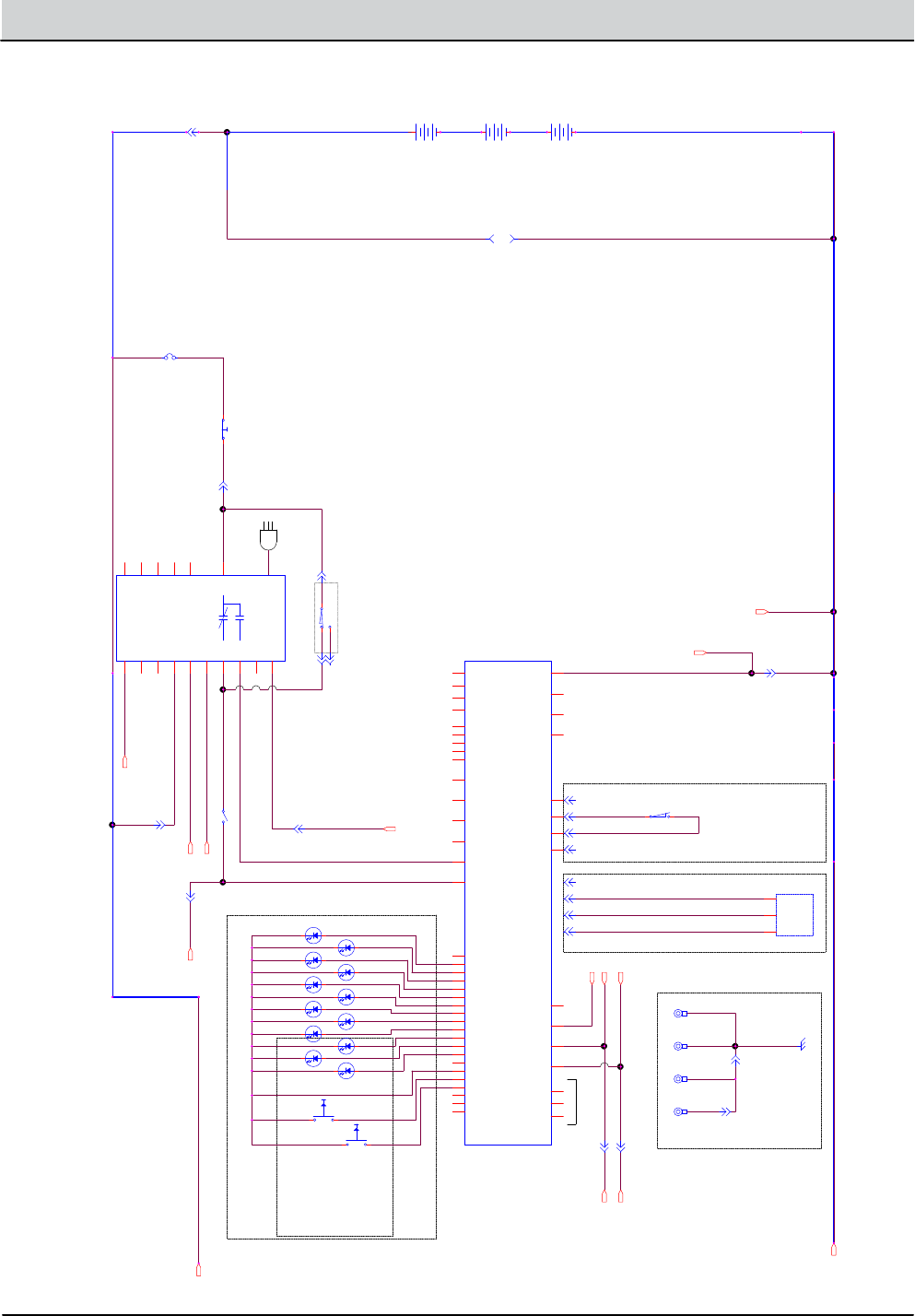
GENERAL INFORMATION
ELECTRICAL SCHEMATIC (PUSH MODEL) - 1 of 2
B5/SpeedGleam5 (3 x 12 vDC)
36 VOLT CONFIGURATIONS
CAN BUS
SW-9:
HOOD DISABLE SWITCH
(OPEN = HOOD UP = MACHINE OFF)
SW-2
13
OFF BOARD CHARGER CABLE (OPTION)
SW-1 = CHARGER INTERLOCK SWITCH
OFF-BOARD CHARGER ONLY: SW.
N.O.
N.C.
COM
POWER ON/OFF
CIRCUITRY
B5 CABLE B+/FUSE ASSY
GROUND
B+
SWITCHED, B+
OPERATOR'S SWITCH/LIGHT PANEL
CABLE, CHARGER
BDI_0
BDI_1
BDI_2
BDI_3
BDI_4
MTR HOT
SERVICE
DB FULL
IRIS
DP LOW
DP MED
DP HIGH
GROUND
INCREASE
DECREASE
AC PLUG
KEY SWITCH
J2-8
J2-2
J2-1
BAIL SWITCH INPUT @ J4-4: 0V OR 5V
0V = NEUTRAL / BURNISH MTR OFF.
5V = MAX. PROPEL / BURNISH MTR ON.
BAIL SWITCH (N.O.)
SW-5:
NO CONNECTION
SENSOR OUTPUT: 0.5 TO 4.5VDC.
0.5V = NEUTRAL
4.5V = MAX. PROPEL
SENSOR REPL. SW-5.
J4-4
J4-1
J4-3
OPT: BAIL POSITION SENSOR ASSY
LED1
LED2
LED3
LED4
LED5
LED7
LED6
LED8
LED9
LED10
LED11
LED12
SW2
SW1
OPT: Active Down Pressure
NOTE: The Active Down Pressure
buttons and LEDs exist on all
machines, but are only visible on
models equipped with automated
down pressure. On models
equipped with mechanical “Set and
Forget™” down pressure, the LH (SW1)
button is used to enter pressure
adjust mode. Refer to the operator’s
manual for more information.
OPT: BAIL SW. HARNESS
CAN GROUND
NO CONNECTION
J4-2
NO CONNECTION
J2-4
J2-3
CAN BUS
RS232 DEBUG
PORT
CAN BUS
STATIC GROUNDING
(PART OF MAIN HARNESS
AND OP.STATION HARNESS)
CABLE, CHARGER
CABLE, CHARGER
1/RED
BLK
1/RED
13/BLK1/RED
1/RED
3/ORA
RED
7/PUR
6/BLU
4/YEL
13/BLK
5/GRN
6/BLU
KLB/31KLB/31 13/BLK
13/BLK
BROWN (+5VDC)
BLACK (SENSOR OUTPUT)
BLU (GROUND)
CAN+ /YEL
CAN- /GRN
4/YEL
4/YEL
7/PUR
5/GRN
30/TAN
31/PNK
113/BLK/WHT
113/BLK/WHT
CAN- /GRN
CAN+ /YEL
105/GRN
105/GRN
105/GRN
105/GRN
105/GRN
13/BLK
TO: BATT. GROUND
13
1
6
CAN+
CAN-
13
113
113
CAN-
CAN+
CAN-
CAN+
13
SW-1
CHARGER: ON BOARD
NC
P2-2
GND
P1-B-
B+
P1-B+
COM
P2-3
CAN+
P2-6
CAN-
P2-10
NO
P2-4
CAN_GND
P2-1
SENSE+
P2-5
SENSE-
P2-14
RESERVED3
P2-11
LED+
P2-12
LED-
P2-13
RESERVED1
P2-8
RESERVED2
P2-9
RETURN
P2-7
OP.STATION
CB-1
2.5A
12 VDC
+ --
BURNISH HEAD
VAC FAN CHASSIS GND. STRAP @ FRAME
INTERFACE MODULE
+5V OUT
J4-1
CAN-
J3-2
CAN+
J3-1
CHARGER INPUT
J7-9
KSI
J7-10
SENSE_GND
J4-3
COMM_GND
J5-1
TX
J5-3
RX
J5-4
V_BUS
J6-1
SHLD_GND
J3-3
N/C
J3-4
SENSOR_IN
J4-4
WIPER OUT
J5-2
GND
J7-8
COM_GND2
J2-3
TX_2
J2-1
RX_2
J2-2
+5VDC_OUT
J7-1
D-
J6-2
D+
J6-3
ID
J6-4
GND_SHIELD
J6-5
LSD_OUT_0
J7-5
LSD_OUT_1
J7-6
LSD_FLYBACK
J7-7
INPUT_0
J7-2
INPUT_1
J7-3
INPUT_2
J7-4
LED_+5VDC_OUT
J9-1
BDI_0_LED
J9-2
BDI_1_LED
J9-3
BDI_2_LED
J9-4
BDI_3_LED
J9-5
BDI_4_LED
J9-6
MTR_HOT_LED
J9-7
SERVICE_LED
J9-8
DB_FULL_LED
J9-9
IRIS_LED
J9-10
DP_1_LED
J9-11
DP_2_LED
J9-12
DP_3_LED
J9-13
SPARE_LED
J9-14
GND_1
J9-15
DP_INC_SW
J9-16
DP_DEC_SW
J9-17
SPARE_SW1
J9-18
SPARE_SW2
J9-19
GND_2
J9-20
NOT USED
J4-2
OPT: BAIL POS. SENSOR
GND
2
+5V
3
OUTPUT
1
12 VDC
+ --
KEY SWITCH
12 VDC
+ --
B5/7, SpeedGleam® 5/7 Service Information (1-14) 2-7
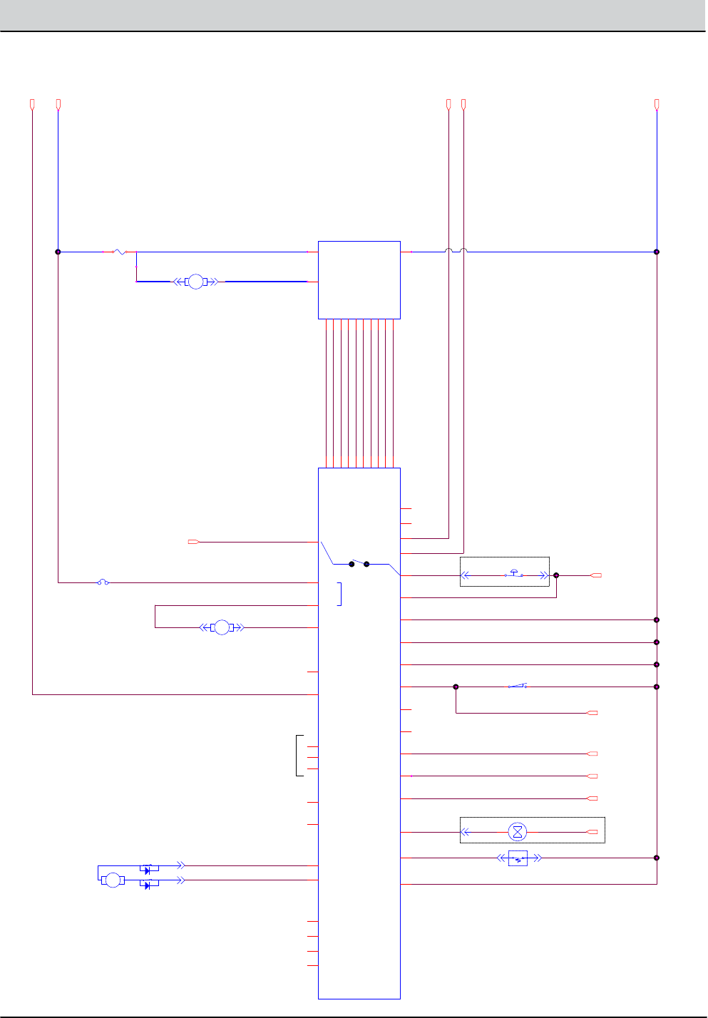
GENERAL INFORMATION
ELECTRICAL SCHEMATIC (PUSH MODEL) - 2 of 2
ENABLE I-DRIVE
CABLE MOTOR TO 1/2 BRIDGE PCB
J5 & J11 (EVEN PINS 2 THROUGH 20)
= GROUND.
GROUND
B+
SWITCHED, FUSED, B+
CAN+
CAN-
RIBBON CABLE ASSY.
I-DRIVE B+ DETECT
E-STOP SWITCH
INTERNAL TO BURNISH MOTOR
FOOTPEDAL / PAD CHANGE
FOOT PEDAL/PAD CHANGE SW.
(GND. = ENABLE BURNISH)
SW-7: N.O.H.C.
I-DRIVE STATUS
I-DRIVE_AUX3
I-DRIVE_AUX2
HOUR METER
5.0 AMPS
OPTIONAL: BURNISH HEAD ACTUATOR
1/2 BRIDGE
MODULE
BASE BURNISHER
MODULE
CABLE B+/FUSE ASSY
RS232 DEBUG
PORT
7-2J6-2J
J2-5
CABLE B+/FUSE ASSY
13/BLK13/BLK
24/YEL
CAN- /GRNCAN- /GRN
6/BLU 6/BLU6/BLU
1/RED
BLU2/BRN
13/BLK 13/BLK2/BRN
6/BLU
CAN+ /YELCAN+ /YEL
11/PNK38/GRY38/GRY
13/BLK13/BLK
13/BLK28/GRY
27/PUR
27/PUR 13/BLK27/PUR
ULB/62ULB/62
LEY/41LEY/41
NRB/21NRB/21
17/PUR
1/RED ULB/61ULB/61
19/WHT
22/BRN
23/ORA
38/GRY
11/PNK
13/BLK17/PUR
25/GRN19/WHT
13/BLK13/BLK
24
13
6
1
CAN-
CAN+
11
27
12
26
14
13
+ -
MTR3
OPTIONAL: VAC FAN
21
BASE CONTROLLER
GND_POWER_A
J12-7
B+_MONITOR
J11-1
HOURMETER+
J10-4
KSI
J10-1
ACT_2
J12-6
B+_B
J12-2
VAC
J12-4
ACT_1
J12-5
GND_RETURN
J5-10
CAN-
J3-2
CAN+
J3-1
I-DRIVE STATUS
J5-5
AUX2 INPUT
J5-3
OPEN
J5-6
MTR TEMP
J10-3
E-STOP OUT
J5-2
AUX3 INPUT
J5-4
SHIELD_GND
J3-3
N/C_1
J3-4
B+ FROM I-DRIVE
J5-7
+5V
J11-3
+12V
J11-5
I_SET
J11-7
I_PEAK
J11-9
OVER_I
J11-11
PWM
J11-13
ENABLE
J11-15
SPARE_2
J11-17
SPARE_1
J11-19
I-DRIVE ENABLE
J5-1
SPARE_A
J5-8
SPARE_B
J5-9
M1_COIL-
J10-5
M1_COIL+
J10-6
B+_A
J12-1
PAD CHANGE
J12-3
GND_POWER_B
J12-8
CAN+_2
J6-1
CAN-_2
J6-2
SHIELD_GND_2
J6-3
N/C_2
J6-4
RX
J2-2
TX
J2-1
RS232_GND
J2-3
GND_RETURN_2
J10-2
FUSE-1
100A
SW-6
MOTOR TEMP. SW. (N.C.)
A B
CB2
15A
MTR2
BURNISHER MOTOR
21
1/2 BRIDGE
B+
J2-1
GND
J4-1
MTR, LOW SIDE
J1-1
B+_OUT
J5-1
+5V
J5-3
+12V
J5-5
I_SET
J5-7
I_PEAK
J5-9
OVER_I
J5-11
PWM
J5-13
ENABLE
J5-15
SPARE_2
J5-17
SPARE_1
J5-19
EXTEND LIMIT SW.
RETRACT LIMIT
BLU
BRN
BLK
RED
MTR4
2
1

2-8 B5/7, SpeedGleam® 5/7 Service Information (1-14)
GENERAL INFORMATION
FUNCTION ENABLED
B5/7, SpeedGleam5/7 OPERATIONAL MATRIX
DISABLED
Burnish Motor - On • Burnish Head Down
• Burnish Bail Activated
• Burnish Head Up
• Burnish Bail Release
• Low Battery Voltage (< 32.5 vDC)
• Load Current Fault
• Battery Charger ON Interlock
• Access Cover Open
Vacuum Fan
(Optional)
• Burnish Head Down
• Burnish Bail Activated
• Burnish Head Up
• Burnish Bail Release
• Low Battery Voltage (< 32.5 vDC)
• Load Current Fault
• Battery Charger ON Interlock
• Access Cover Open
MOM001
Propel (Optional on B/SG5) • Battery Charger ON Interlock
• Neutral - Ready State
• Low Battery Voltage (< 30.0 vDC)
• Load Current Fault
• Access Cover Open
• Neutral Input at Power Up
• Burnish/Propel Bail
Activated

B5/7, SpeedGleam® 5/7 Service Information (1-14) 2-9
GENERAL INFORMATION
FASTENER TORQUE
Thread
Size
SAE
Grade 1
SAE
Grade 2
Carriage
Bolts
Thread
Cutting
Thread
Rolling
SAE
Grade 5
Socket &
Stainless
Steel
SAE
Grade 8
Headless
Socket Set
Screws
Square
Head Set
Screws
4 (.112) (5) - (6.5) (4) - (6)
Inch Pounds
5 (.125) (6) - (8) (9) - (11)
6 (.138) (7) - (9) (20) - (24) (9) - (11)
8 (.164) (12) - (16) (40) - (47) (17) - (23)
10 (.190) (20) - (26) (50) - (60) (31) - (41)
1/4 (.250) 4 - 5 5 - 6 7 - 10 7 - 10 10 - 13 6 - 8 17 - 19
Foot Pounds
5/16 (.312) 7 - 9 9 - 12 15 - 20 15 - 20 20 - 26 13 - 15 32 - 38
3/8 (.375) 13 - 17 16 - 21 27 - 35 36 - 47 22 - 26 65 - 75
7/16 (.438) 20 - 26 26 - 34 43 - 56 53 - 76 33 - 39 106 - 124
1/2 (.500) 27 - 35 39 - 51 65 - 85 89 - 116 48 - 56 162 - 188
5/8 (.625) 80 - 104 130 - 170 171 - 265 228 - 383
3/4 (.750) 129 - 168 215 - 280 313 - 407 592 - 688
1 (1.000) 258 - 335 500 - 650 757 - 984 1281 - 1489
Thread
Size
4.8/5.6 8.8
Stainless Steel
10.9 12.9 Set
Screws
M3 43 - 56 Ncm 99 - 128 Ncm 139 - 180 Ncm 166 - 215 Ncm 61 - 79 Ncm
M4 99 - 128 Ncm 223 - 290 Ncm 316 - 410 Ncm 381 - 495 Ncm 219 - 285 Ncm
M5 193 - 250 Ncm 443 - 575 Ncm 624 - 810 Ncm 747 - 970 Ncm 427 - 554 Ncm
M6 3.3 - 4.3 Nm 7.6 - 9.9 Nm 10.8 - 14 Nm 12.7 - 16.5 Nm 7.5 - 9.8 Nm
M8 8.1 - 10.5 Nm 18.5 - 24 Nm 26.2 - 34 Nm 31 - 40 Nm 18.3 - 23.7 Nm
M10 16 - 21 Nm 37 - 48 Nm 52 - 67 Nm 63 - 81 Nm
M12 28 - 36 Nm 64 - 83 Nm 90 - 117 Nm 108 - 140 Nm
M14 45 - 58 Nm 102 - 132 Nm 142 - 185 Nm 169 - 220 Nm
M16 68 - 88 Nm 154 - 200 Nm 219 - 285 Nm 262 - 340 Nm
M20 132 - 171 Nm 300 - 390 Nm 424 - 550 Nm 508 - 660 Nm
M22 177 - 230 Nm 409 - 530 Nm 574 - 745 Nm 686 - 890 Nm
M24 227 - 295 Nm 520 - 675 Nm 732 - 950 Nm 879 - 1140 Nm
METRIC
SAE (STANDARD)

2-10 B5/7, SpeedGleam® 5/7 Service Information (1-14)
GENERAL INFORMATION
MODEL (20 in / 510 mm) Push Model (20 in / 510 mm) Drive Model
Length 59 in / 1499 mm 59 in / 1499 mm
Width 24.5 in / 622 mm 24.5 in / 622 mm
Height 43 in / 1092 mm 43 in / 1092 mm
Weight 193 lb / 87.5 kg 198 lb / 90 kg
Weight with batteries 507 lb / 230 kg 572 lb / 259 kg
Burnish path width 20 in / 510 mm 20 in / 510 mm
Productivity rate (max.) 16,260 ft/hr / 1,500 m/hr 20,000 ft/hr / 1,900 m/hr
Productivity rate (practical) 13,500 ft/hr / 1,200 m/hr 18,000 ft/hr / 1,670 m/hr
Burnishing speeds (Variable) Pad Assist Min: 100 fpm / 30 mpm
Max: 200 fpm / 60 mpm
Transport speed (max.) n/a Fwd: 240 fpm/ 73 mpm
Rev: 144 fpm/ 44 mpm
Aisle turn (min.) 60 in / 1,524 mm 60 in / 1,524 mm
Grade level (max.) Burnishing: 9%, Transport: 19.5% Burnishing: 9%, Transport: 19.5%
Propel Motor n/a 24 V, 14 A, .363 hp / 0.27 kW, 271 W
Pad motor 36 V, 75 A, 2.8 hp max / 2.1 kW 36 V, 75 A, 2.8 hp max / 2.1 kW
Pad Pressure Variable Variable
Pad speed 2100 rpm 2100 rpm
Vacuum motor (Active Dust Collection) 36 V, 5 A, 180W / 0.18 kW 36 V, 5 A, 180W / 0.18 kW
HEPA ltration (Active Dust Collection) 99.97% @ 0.3 micron 99.97% @ 0.3 micron
Filtration (Passive Dust Collection) 95% @ 0.3 micron 95% @ 0.3 micron
Dust bag capacity 1.27 qt / 1.4 l 1.27 qt / 1.4 l
Machine Voltage 36 VDC 36 VDC
Battery capacity 3 - 12V, 185 Ah Wet/lead-acid (std.)
3 - 12V, 225 Ah Wet/lead-acid (opt.)
3 - 12V, 234 Ah AGM (opt.)
3 - 12V, 225 Ah Wet/lead-acid (std.)
3 - 12V, 234 Ah AGM (opt.)
Total power consumption 60 A / 1.9 kw nominal 60 A / 1.9 kw nominal
Run time (max.) 2.5 hours 2.5 hours
Battery charger 120 VAC, 60 Hz, 36 VDC, 25 A 120 VAC, 60 Hz, 36 VDC, 25 A
220/240 VAC, 60 Hz, 36 VDC, 25 A 220/240 VAC, 60 Hz, 36 VDC, 25 A
Protection grade IPX3 IPX3
*Sound pressure level LpA
(Active Dust Colletion Model)
64 dB(A) 64 dB(A)
*Sound pressure level LpA
(Passive Dust Colletion Model)
65 dB(A) 65 dB(A)
*Sound uncertainty KpA 3.0 dB(A) 3.0 dB(A)
*Sound power level LwA + uncertainty KwA xx dB(A) xx dB(A)
*Machine vibration at hand-arm <2.5 m/s <2.5 m/s
*Machine vibration uncertainty K 0.2 m/s 0.2 m/s
Ambient operating temperature Min: 32°F/0°C
Max: 110°F/43°C
Min: 32°F/0°C
Max: 110°F/43°C
B5/ SpeedGleam® 5 GENERAL MACHINE DIMENSIONS/CAPACITIES/PERFORMANCE
*Values per EN 60335-2-72
Specications are subject to change without notice.

B5/7, SpeedGleam® 5/7 Service Information (1-14) 2-11
GENERAL INFORMATION
MODEL (24 in / 610 mm) Drive Model (27 in / 690 mm) Drive Model
Length 61.5 in / 1562 mm 63 in / 1602 mm
Width 30 in / 762 mm 31.5 in / 800 mm
Height 43 in / 1092 mm 43 in / 1092 mm
Weight 246 lb / 111.5 kg 254 lb / 115 kg
Weight with batteries 616 lb / 279 kg 797 lb / 362 kg
Burnish path width 24 in / 610 mm 27 in / 690 mm
Productivity rate (max.) 24,000 ft/hr / 2,200 m/hr 27,000 ft/hr / 2,500 m/hr
Productivity rate (practical) 22,000 ft/hr / 2,000 m/hr 25,000 ft/hr / 2,300 m/hr
Burnishing speeds (Variable) Min: 100 fpm / 30 mpm
Max: 200 fpm / 60 mpm
Min: 100 fpm / 30 mpm
Max: 200 fpm / 60 mpm
Transport speed (max.) Fwd: 240 fpm/ 73 mpm
Rev: 144 fpm/ 44 mpm
Fwd: 240 fpm/ 73 mpm
Rev: 144 fpm/ 44 mpm
Aisle turn (min.) 62.5 in / 1,588 mm 64 in / 1,626 mm
Grade level (max.) Burnishing: 9%, Transport: 19.5% Burnishing: 9%, Transport: 19.5%
Propel Motor 24 V, 14 A, .363 hp / 0.27 kW, 271 W 24 V, 14 A, .363 hp / 0.27 kW, 271 W
Pad motor 36 V, 90 A, 3.6 hp max / 2.6 kW 36 V, 90 A, 3.6 hp max / 2.6 kW
Pad Pressure Variable Variable
Pad speed 1875 rpm 1875 rpm
Vacuum motor (Active Dust Collection) 36 V, 5 A, 180W / 0.18 kW 36 V, 5 A, 180W / 0.18 kW
HEPA ltration (Active Dust Collection) 99.97% @ 0.3 micron 99.97% @ 0.3 micron
Filtration (Passive Dust Collection) 95% @ 0.3 micron 95% @ 0.3 micron
Dust bag capacity 1.27 qt / 1.4 l 1.27 qt / 1.4 l
Machine Voltage 36 VDC 36 VDC
Battery capacity 6 - 6V, 240 Ah Wet/lead-acid (std.)
6 - 6V, 312 Ah AGM (opt.)
6 - 6V, 360 Ah Wet/lead-acid (opt.)
6 - 6V, 240 Ah Wet/lead-acid (std.)
6 - 6V, 312 Ah AGM (opt.)
6 - 6V, 360 Ah Wet/lead-acid (opt.)
Total power consumption 75 A / 2.4 kw nominal 75 A / 2.4 kw nominal
Run time (max.) 3 hours 3 hours
Battery charger 120 VAC, 60 Hz, 36 VDC, 25 A 120 VAC, 60 Hz, 36 VDC, 25 A
220/240 VAC, 60 Hz, 36 VDC, 25 A 220/240 VAC, 60 Hz, 36 VDC, 25 A
Protection grade IPX3 IPX3
*Sound pressure level LpA
(Active Dust Colletion Model)
63 dB(A) 63 dB(A)
*Sound pressure level LpA
(Passive Dust Colletion Model)
65 dB(A) 65 dB(A)
*Sound uncertainty KpA 3.0 dB(A) 3.0 dB(A)
*Sound power level LwA + uncertainty KwA xx dB(A) xx dB(A)
*Machine vibration at hand-arm <2.5 m/s <2.5 m/s
*Machine vibration uncertainty K 0.2 m/s 0.2 m/s
Ambient operating temperature Min: 32°F/0°C
Max: 110°F/43°C
Min: 32°F/0°C
Max: 110°F/43°C
B7/ SpeedGleam® 7 GENERAL MACHINE DIMENSIONS/CAPACITIES/PERFORMANCE
*Values per EN 60335-2-72
Specications are subject to change without notice.

2-12 B5/7, SpeedGleam® 5/7 Service Information (1-14)
GENERAL INFORMATION
SPECIFICATIONS
Component Measure
Actuator, Scrub head lift 1 - 3 Amps Continuous
Motor, Vacuum Fan 5 Amps
Motor, Propelling
(transport speed)
Variable to 14 Amps, 24 V
B5/ SG5 - Actuator Pressure Burnish Motor Measure
Down Pressure 1 LED 42-49 Amps
Down Pressure 2 LEDs 57-64 Amps
Down Pressure 3 LEDs 72-79 Amps
B7/ SG7 - Actuator Pressure Burnish Motor Measure
Down Pressure 1 LED 57-64 Amps
Down Pressure 2 LEDs 72-79 Amps
Down Pressure 3 LEDs 87-94 Amps
B5/ SG5 - Mechanical Pressure Burnish Motor Measure - Mechanical Pressure Adjust Mode
BDI LED #1 (LH) Less than 42 Amps (Blink), 42-49 Amps (Steady)
BDI LED #2 49-57 Amps
BDI LED #3 57-64 Amps
BDI LED #4 64-72 Amps
BDI LED #5 (RH) 72-79 Amps (Steady), Greater than 79 Amps (Blink)
B7/ SG7 - Mechanical Pressure Burnish Motor Measure - Mechanical Pressure Adjust Mode
BDI LED #1 (LH) Less than 56.5 Amps (Blink), 57-64 Amps (Steady)
BDI LED #2 64-72 Amps
BDI LED #3 72-79 Amps
BDI LED #4 79-87 Amps
BDI LED #5 (RH) 87-94 Amps (Steady), Greater than 94 Amps (Blink)
ELECTRICAL COMPONENTS (For Reference Only)
Specications are subject to change without notice.
B5/7, SpeedGleam® 5/7 Service Information (1-14) 2-13
GENERAL INFORMATION
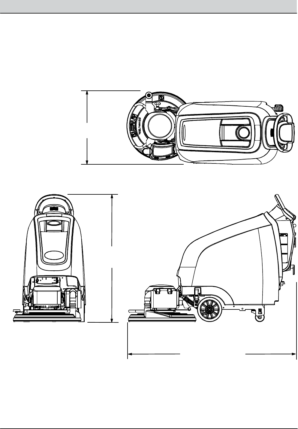
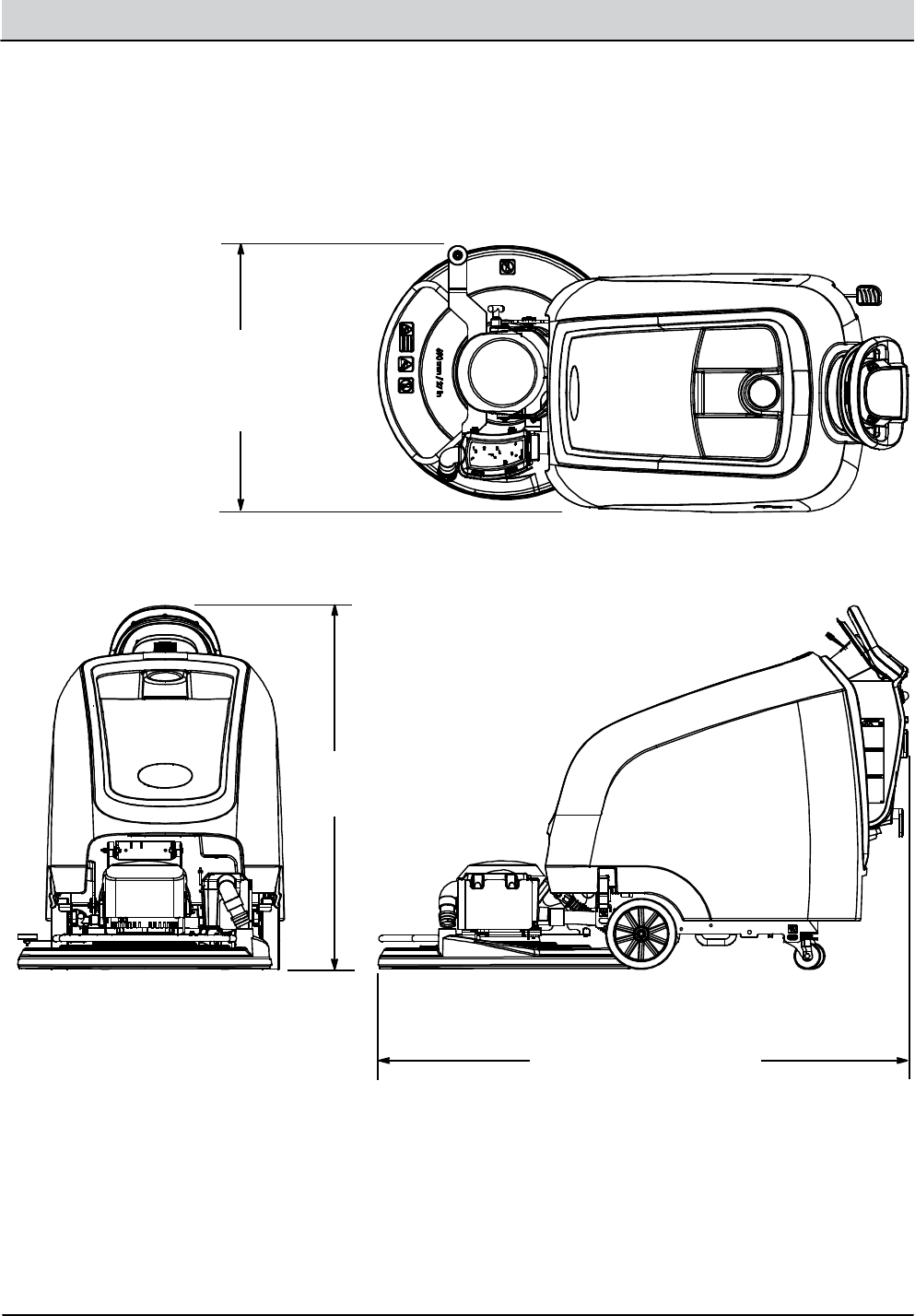
SPECIFICATIONS
24.5 in / 622 mm
59 in / 1,499 mm
43 in
1,092 mm
B5/ SpeedGleam® 5 MACHINE DIMENSIONS
2-14 B5/7, SpeedGleam® 5/7 Service Information (1-14)
GENERAL INFORMATION
SPECIFICATIONS
30 in / 762 mm
(24 in / 610 mm Model)
43 in
1,092 mm
31.5 in / 800 mm
(27 in / 690 mm Model)
63 in / 1,602 mm
(27 in / 690 mm Model)
61.5 in / 1,562 mm
(24 in / 610 mm Model)
B7/ SpeedGleam® 7 MACHINE DIMENSIONS

MAINTENANCE
SECTION 3
3-1
B5/7, SpeedGleam® 5/7 Service Information (1-14)
Maintenance
MAINTENANCE CHART .....................32
AFTER DAILY USE .......................33
AFTER WEEKLY USE .....................33
AFTER EVERY 50 HOURS OF USE ........ 34
AFTER EVERY 100 HOURS OF USE .......34
AFTER EVERY 200 HOURS OF USE .......34
AFTER EVERY 1000 HOURS OF USE ...... 35
BATTERY MAINTENANCE ..................35
SEALED/AGM BATTERIES ............... 35
WET/LEADACID BATTERIES ............ 35
HYDROLINK™ BATTERY WATERING
SYSTEM OPTION ................... 36
MACHINE JACKING ........................ 37
PUSHING TOWING AND TRANSPORTING
THE MACHINE .......................... 37
STORING MACHINE ........................ 38
Contents Page
3-2 B5/7, SpeedGleam® 5/7 Service Information (1-14)
MAINTENANCE
MAINTENANCECHART
3
4
11
8
2
5
1
6
9
10
7
Interval/
Hours
Person
Resp.KeyDescription Procedure
DailyO 1 BatteriesCharge
O 2 BurnishingpadCheck, flip or replace
O 3 Dust collectionbagCheck, replace
O 4 Vacuumhose Check, clean
O 5 Burnishingheaddust skirt Check for dry floor finish chunks
Weekly O 1 Battery electrolyte level Check, adddistilledwater if low
50 Hours O 5 Burnishingheaddust skirt Check for wearanddamage
O 6 BurnishingheadCleanwith air pressure hose
O 7 MachineCleanwith damp cloth
100Hours O 1 HydroLINK Battery watering system
(option)
Check hoses and connections for
damageandwear
200Hours O 1 Batteries, terminalsand cablesCheck and clean
O 8 Vacuum HEPA filter
(Active Dust Control Model)
Check, clean, replace
750Hours T 9 Propel motor (Drive Model)Replace carbon brushes
1000Hours T 10 Headlift bushings, 4 points Inspect, replace bushings
T 11 Pad motor Replace carbon brushes
O = Operator T = Trained Personnel
B5/7, SpeedGleam® 5/7 Service Information (1-14) 3-3
MAINTENANCE
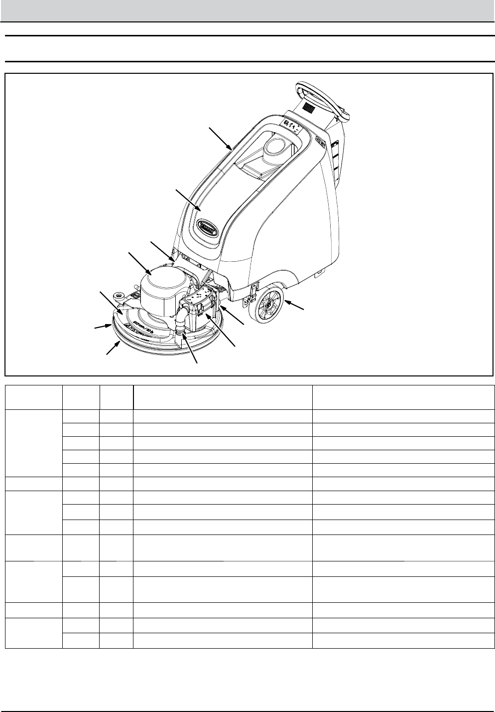
MACHINE MAINTENANCE
To keep the machine in goodworking condition, simply
perform the following maintenance procedures.
FOR SAFETY: Before leaving or servicingmachine,
stop on level surface, turn off machine, remove key
and set parking brake if equipped.
FOR SAFETY: When servicingmachine wear
personal protection equipment as needed. All
repairs must be performed by trained personnel
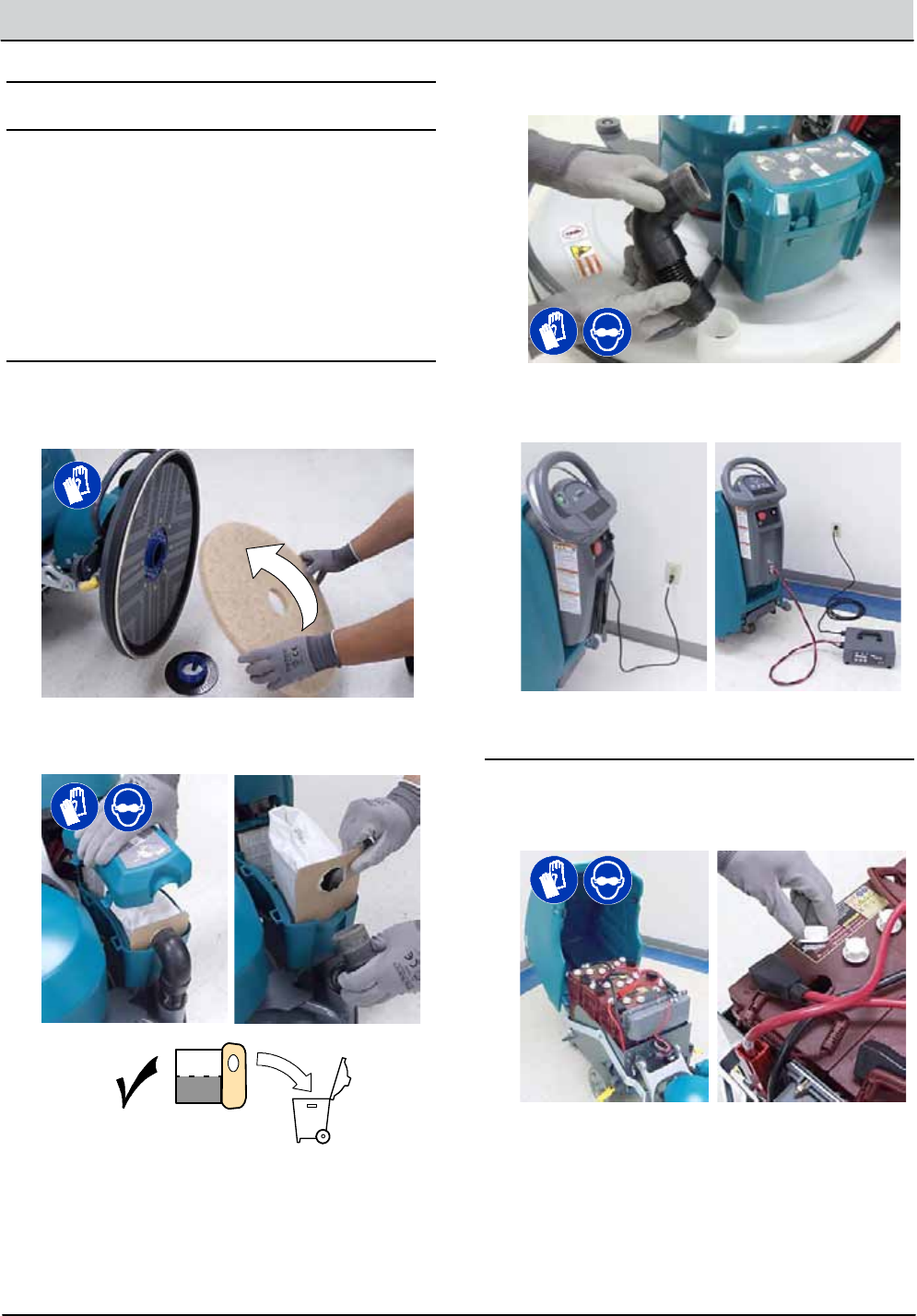
AFTER DAILY USE
1. Flip the burnishingpad over or change toanew
pad (Figure 35).
FIG. 35
2. Check the dust collectionbag for fullness. Replace
bagwhenhalf full (Figure 36).
FIG. 36
3. Check vacuumhose for clogging.Cleanhose as
necessary (Figure 37).
FIG. 37
4. Charge batteries (Figure 38). See CHARGING
BATTERIES.
ON- BO
A
RD CHARGEROFF- BOARDCHARGER
FIG. 38
AFTER WEEKLY USE
Check the electrolyte level in allbatteries (Figure 39).
See BATTERY MAINTENANCE.
FIG. 39
3-4 B5/7, SpeedGleam® 5/7 Service Information (1-14)
MAINTENANCE
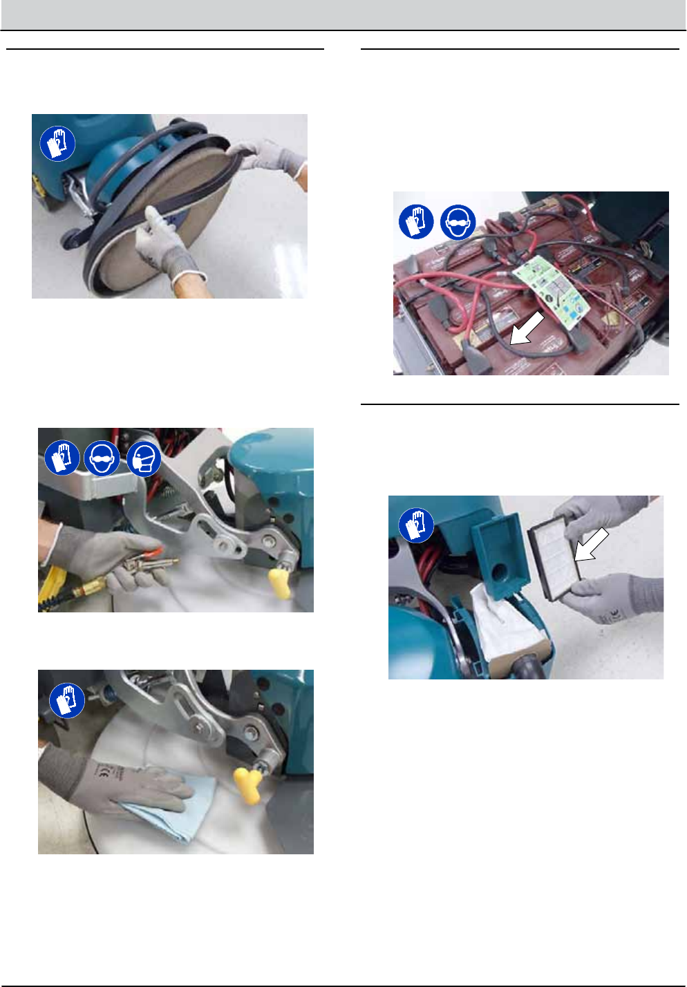
AFTER EVERY 50 HOURS OF USE
1. Check the dust skirt for wearordamage
(Figure 40). Replace if worn or damaged.
FIG. 40
2. Clean the burnishingheadandpad motor of any
dust buildup usinganair pressure hose (Figure
41). Maximum air pressure 100 psi / 690 kPa.
FOR SAFETY: When servicingmachine, wear
appropriate personal protection equipment as
needed
FIG. 41
3. Clean the outside surface of the machinewith an
allpurpose cleaneranddamp cloth (Figure 42).
FIG. 42
AFTER EVERY 100 HOURS OF USE
If machine is equippedwith the optional HydroLINK
battery watering system, check the wateringhoses and
connections for damageandwear (Figure 43). Replace
system if damaged.
FOR SAFETY: When servicing batteries, wear
personal protection equipment as needed. Avoid
contactwith batteryacid.
FIG. 43
AFTER EVERY 200 HOURS OF USE
1. Cleanbatteriesand check for loose battery cable
connections (See BATTERY MAINTENANCE).
2. Replace the HEPA filter if model is equippedwith
the active dust control collectionoption (Figure 44).
FIG. 44
B5/7, SpeedGleam® 5/7 Service Information (1-14) 3-5
MAINTENANCE
AFTER EVERY 1000 HOURS OF USE
Inspect the fourbushings at the headlift bracket
assembly for wear (Figure 45). If you experience head
bounce or vibration,have the bushings replaced.
FIG. 45
MOTOR MAINTENANCE
Replace motor carbon brushesasindicated.Contact
trainedpersonnel for carbon brush replacement.
Carbon Brush Replacement Hours
Propel Motor (Drive Model) 750
Pad Motor 1000
BATTERY MAINTENANCE
FOR SAFETY: Before servicingmachine, stop on
level surface, turn off machine, remove key and set
parking brake if equipped.
The lifetime of the batteriesislimited to the number of
charges the batteries receive. To get the most life from
the batteries, only recharge the batteries when the
battery discharge indicator begins to flash. It is also
important to maintain the properelectrolyte levels
during the life of the battery.
Your machine is equippedwith eitherwet/lead- acid or
sealed AGM batteries supplied by Tennant.
FOR SAFETY: When servicingmachine, wear
personal protection equipment as needed. Avoid
contactwith batteryacid.
FOR SAFETY: When servicingmachine, keep all
metal objects off batteries.
SEALED AGM BATTERIES
The sealed AGM batteries are maintenance free and
do not require any attention other than routine charging
as described in this manual.
WET/LEAD- ACID BATTERIES
The wet/lead- acid batteries require routine
maintenance as describedbelow.
NOTE: If your machine is equippedwith the HydroLINK
battery watering system option, see HYDROLINK
BATTERY WATER SYTEM.
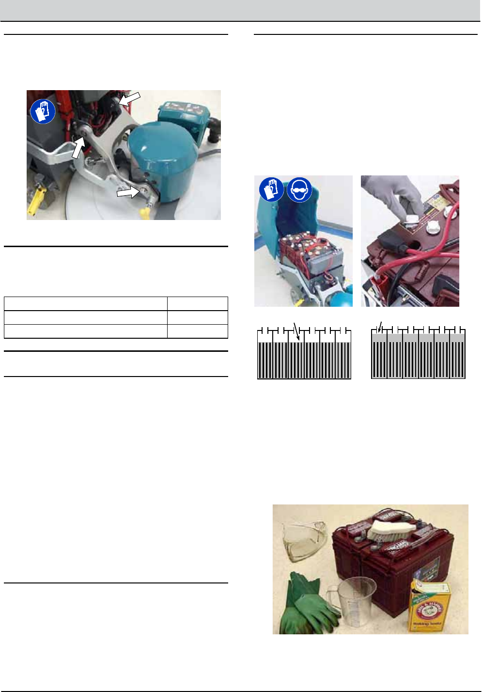
Check the battery electrolyte level weekly. The
electrolyte level should be slightly above the battery
plates as shown (Figure 46). Add distilledwater if low.
DO NOT OVERFILL. The electrolyte will expandand
may overflowwhen charging.
Before Charging After Charging
The levelshould be slightly
above the battery plates The levelshould be
slightly below the sight
tubes
FIG. 46
After every 200hours of use, check for loose battery
connectionsand clean the surface of the batteries,
including terminalsand cable clamps to preventbattery
corrosion. Useascrub brush withastrong mixture of
baking sodaandwater (Figure 47). Do not remove
battery capswhen cleaningbatteries.
FIG. 47
3-6 B5/7, SpeedGleam® 5/7 Service Information (1-14)
MAINTENANCE
HYDROLINK™BATTERY WATERING SYSTEM
(OPTION)
The followinginstructions are for modelsequippedwith
the HydroLINK battery watering system option.
The optionalHydroLINK battery wateringsystem
provides a safe andeasy way to maintain the proper
electrolyte levels in yourbatteries.
Thisbattery watering system is also offered as an
aftermarket kit (p/n 9010301). It is designed exclusively
for Trojan®wet/lead- acid batteries.
FOR SAFETY: When servicingmachine, wear
personal protection equipment as needed. Avoid
contactwith batteryacid.
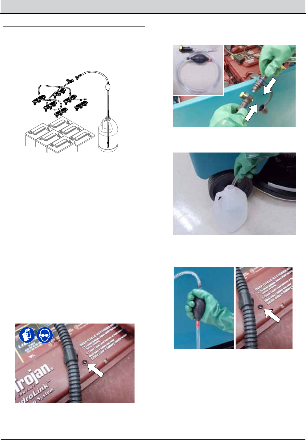
Before using the battery watering system check hoses
and connections for damage or wear.
1. Fully charge batteries prior to using the battery
watering system. Do notaddwater to batteries
before charging, the electrolyte level will expand
and may overflow when charging.
2. After chargingbatteries, check the battery
electrolyte level indicators located on the battery
covers (Figure 48). If the level indicator is white
addwater as described in the following
instructions. If the level indicators are black the
electrolyte is at the correct level, no water is
required.
FIG. 48
3. Locate the battery fillhose couplerinside the
battery compartment. Remove the dust cap and
connect the handpump hose (Figure 49).
FIG. 49
4. Submerge the otherend of the handpump hose
intoabottle of distilledwater (Figure 50).
Distilled
Water
FIG. 50
5. Squeeze the bulb on the handpump hose until firm
(Figure 51). The level indicators will turn black
when full.
FIG. 51
6. After addingwater, replace the dust cap on the
battery fillhose and store the handpump hose
inside the machine’s battery compartment for future
use.
B5/7, SpeedGleam® 5/7 Service Information (1-14) 3-7
MAINTENANCE
MACHINE JACKING
FOR SAFETY: Before leaving or servicing
machine, stop on level surface, turn off machine
and remove key.
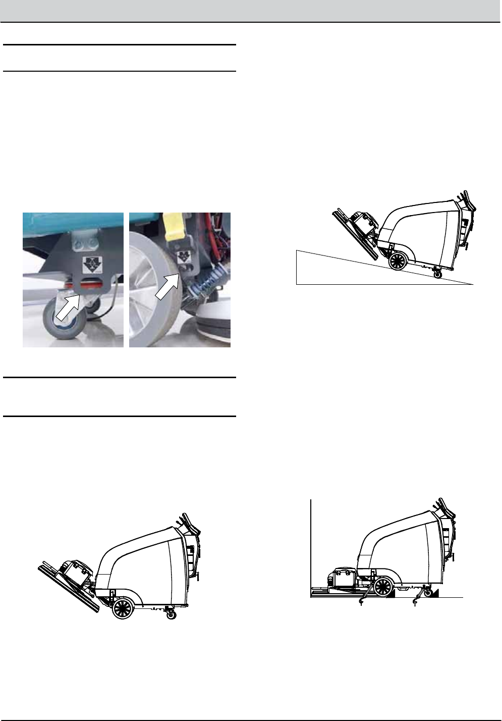
Use the designated jackinglocations for jacking up the
machine (Figure 52). Useajack capable of supporting
the weight of the machine. Position the machine on a
flat, level surface andblock the tires before jacking.
FOR SAFETY: When servicingmachine, jack
machine up at designated locationsonly. Use jack
or hoist that will support machine weight. Block
machine up with jack stands.
FIG. 52
LOADING/UNLOADING MACHINE FOR
TRANSPORTING
When transporting the machine by use of trailer or
truck, carefully follow the loadingand tie- down
procedure:
1. Raise the burnishinghead to the transport position
to preventpotentialheaddamagewhen ramp
loading machine on truck or trailer (Figure 53).
FIG. 53
2. Usearamp that can support the machineweight
andoperator and carefullyload machine. Do not
operate the machine onaramp incline that
exceeds a 19.5% gradelevel (Figure 54). A winch
must be used when ramp incline exceeds a 19.5%
gradelevel.
FOR SAFETY: When loading/unloadingmachine
onto/off truck or trailer, usearamp that can
support the machine weight and operator.
Do notoperate the machine on a rampincline that
exceedsa19.5% grade level. Use tie- down straps
to secure machine to truck or trailer.
19.5% maximum ramp grade
FIG. 54
3. Once loaded,position the front of the machine up
against the front of the trailer or truck. Lower the
burnishinghead to the floorand turn the key off
(Figure 55).
4. Placeablock behindeach wheel (Figure 55).
5. Using tie- down straps, secure the frontand rear of
the machine using the four tie- down brackets
located on the machine frame (Figure 55). It may
be necessary to install tie-down brackets to the
floor of your trailer or truck. Do not use the
burnishingheadlift pedal as a tie down.
FIG. 55
6. Whenunloading machine, carefullyback the
machinedown the ramp. Do notunload machine
going in the forward direction.
3-8 B5/7, SpeedGleam® 5/7 Service Information (1-14)
MAINTENANCE
STORING MACHINE
The following steps should be taken when storing the
machine for extendedperiods of time.
1. Charge the batteriesbefore storing machine to
prolong the life of the batteries. Recharge batteries
every 3 months.
2. Raise the burnishinghead off the floor.
3. Park the machine inacool, dry area.
4. Turn machine off and remove key.
NOTE: To preventpotential machinedamage store
machine inarodentandinsect free environment.
WARNING: To Reduce the Risk of Fire,
Explosion, Electric Shock or Injury do notexpose
the machine to rain, store indoors.
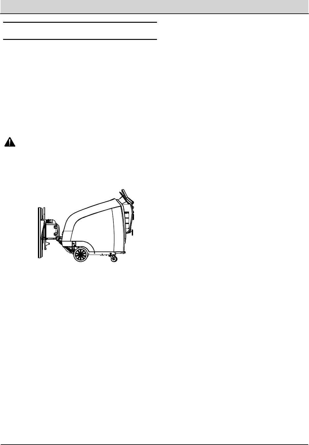
5. For storage areaswith limited space, raise the
head as shown (Figure 56).
FIG. 56

TroubleshooTing
BDI FAULTS ................................42
SUBSYSTEM TROUBLESHOOTING .......... 44
BURNISH MOTOR .......................44
BATTERY CHARGER ON BOARD ........46
BATTERY CHARGER OFF BOARD .......48
POWERUP CIRCUIT ....................410
PROPEL OPTION .....................412
BURNISH HEAD
LIFT ACTUATOR OPTION ........... 414
VACUUM FAN OPTION ................416
TROUBLESHOOTING
SECTION 4
Contents Page
4-1
B5/7, SpeedGleam® 5/7 Service Information (1-14)
4-2 B5/7, SpeedGleam® 5/7 Service Information (1-14)
TROUBLESHOOTING
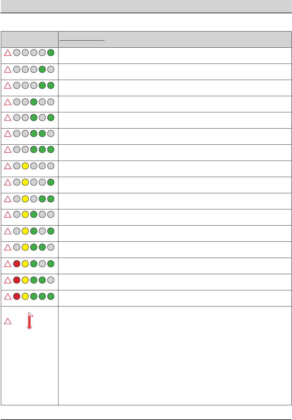
Blinking BDI Fault Cause
Correction
Base module power supply failure
Correct fault condition
Actuator circuit open (option)
Correct fault condition
Burnish motor circuit open
Correct fault condition
Vacuum motor circuit open (option)
Correct fault condition
Actuator/Vac breaker tripped (option)
Correct fault condition, disconnect battery, reset circuit breaker
Propel motor breaker tripped (option)
Correct fault condition, disconnect battery, reset breaker
Propel motor circuit open (option)
Correct fault condition
Charger over temperature
Move machine to well-ventilated area
Burnish motor over-current
Correct fault condition
Software load failure
Recongure machine software
Charger no-load warning
Check connection from charger/battery
Charger timeout
Correct fault condition
CAN-bus communication fault
Correct fault condition
Burnish motor circuit shorted
Correct fault condition
Base controller module failure
Replace base controller module
E-Stop switch activated
Release E-Stop and cycle key switch
Burnish motor high temperature
Allow burnish motor to cool down. Fault will clear once cooled.
!
!
!
!
!
!
!
!
!
!
!
!
!
!
!
!
!
BDI (Battery Discharge Indicator) Faults
B5/7, SpeedGleam® 5/7 Service Information (1-14) 4-3
TROUBLESHOOTING
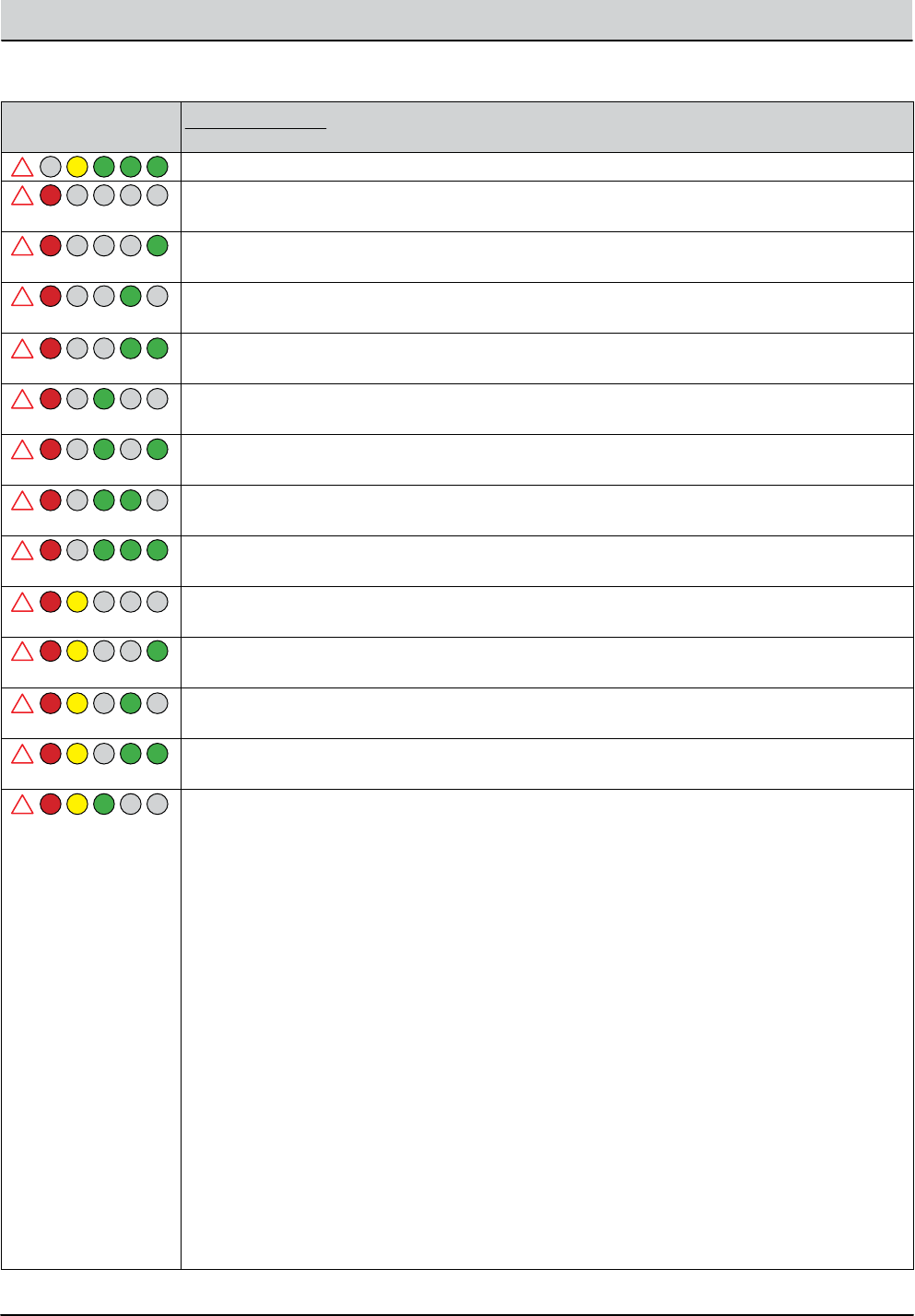
Blinking BDI Fault Cause
Correction
Not Used - Reserved for later use
Burnish motor voltage loss
Correct fault condition
Propel system iDrive fault (option)
Correct fault condition
Propel motor circuit shorted (option)
Correct fault condition
Burnish motor hardware over-current
Correct fault condition
Burnish motor over-current
Correct fault condition
High throttle fault at power-up
Correct fault condition
Half-Bridge module failure
Replace half-bridge module
Vacuum motor hardware over-current
Correct fault condition
Vacuum motor over-current, Level 1
Correct fault condition
Vacuum motor over-current, Level 2
Correct fault condition
Vacuum motor circuit shorted
Correct fault condition
Actuator stall fault (option)
Correct fault condition
Charger fault - detected by charger
Correct fault condition
!
!
!
!
!
!
!
!
!
!
!
!
!
!
BDI (Battery Discharge Indicator) Faults
4-4 B5/7, SpeedGleam® 5/7 Service Information (1-14)
TROUBLESHOOTING
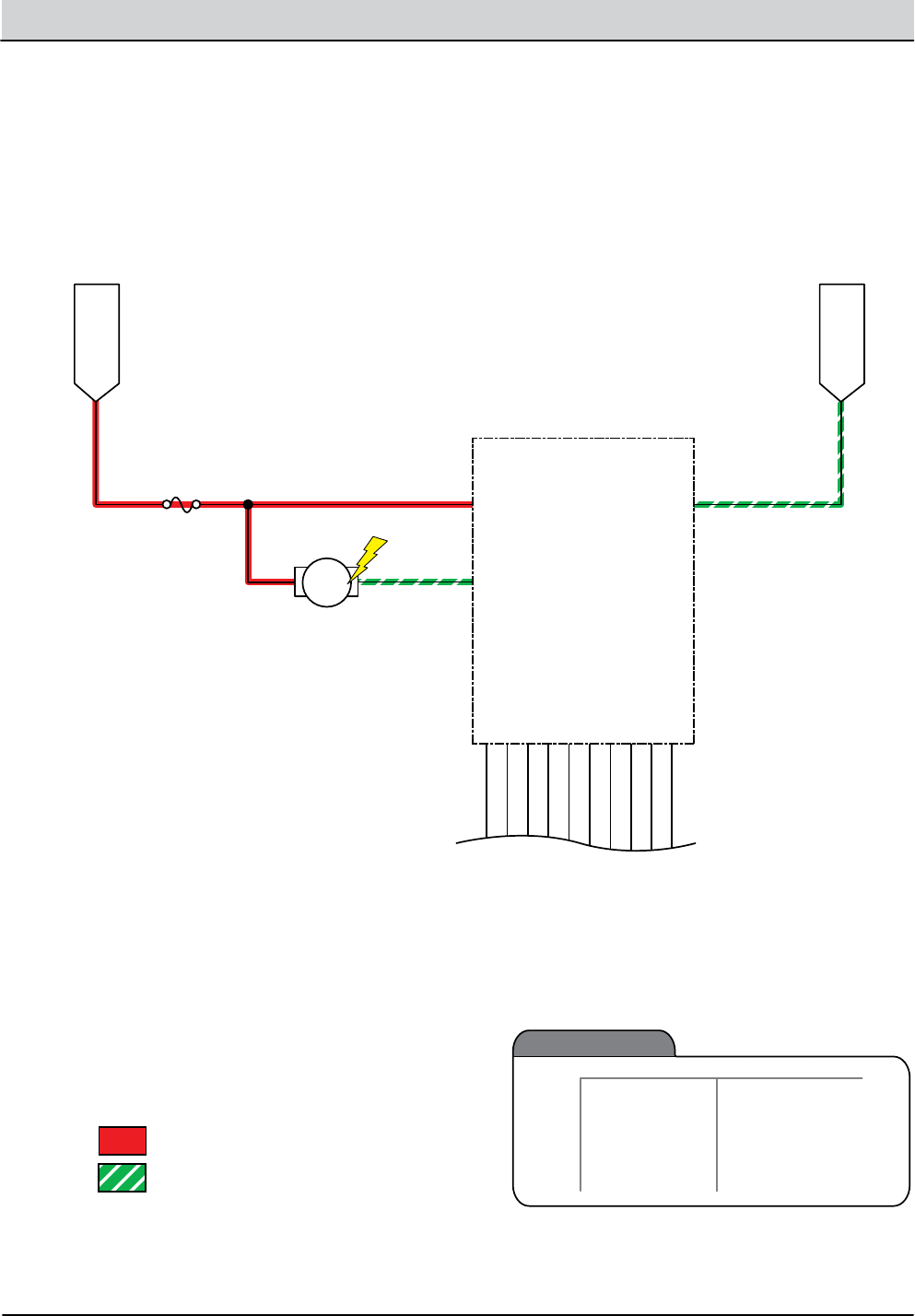
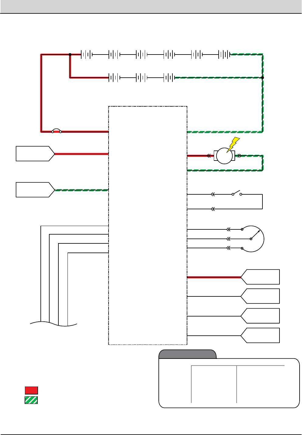
Burnish Motor Failed to Turn ON
Battery Positive +
Battery Negative -
PMC011
MTR
Burnish Motor
RIBBON CABLE TO
BASE CONTROLLER
FUSE-1
100A
HALF-BRIDGE MODULE
MOTOR, LOW SIDE
B+ GND
SPARE_1
SPARE_2
ENABLE
PWM
OVER_I
I_PEAK
I_SET
+12V
+5V
B+_OUT
J5-19
J5-17
J5-15
J5-13
J5-11
J5-9
J5-7
J5-5
J5-3
J5-1
Unswitched B+
Battery (-)
Ground
1/RED
2/BRN 13/BLK
BLU
2/BRN
Burnish
Motor
Enabled
• Burnish head down
• Burnish bail activated
Disabled
Operational Matrix:
• Burnish Head Up
• Burnish Bail Release
• Low Battery Voltage(< 32.5 V)
• Load Current Fault
• Battery Charger ON Interlock
• Access Cover Open
• High Motor Temp

B5/7, SpeedGleam® 5/7 Service Information (1-14) 4-5
TROUBLESHOOTING
Burnish Motor Failed to Turn ON
sTep AcTion VAlue(s) Yes no
1• Key On
• Enable burnish motor
• Is there a blinking BDI fault present?
See “BDI
Faults” in the
Troubleshoot-
ing section of
this manual
Go to Step #2
2• Key O
• Disconnect burnish motor power cables
• Apply battery voltage directly to the burnish motor
using jumper cables
• Does the burnish motor turn On?
Go to Step #3 Repair or re-
place burnish
motor
3• Key O
• Reconnect burnish motor power cables
• Disconnect ribbon cable from Half-Bridge and Base
Controller modules
• Inspect the ribbon cable and terminals for damage
• Test each ribbon wire segment for continuity
• Is there an open or damaged ribbon wire segment?
Replace rib-
bon cable
Go to Step #4
4• Key On
• Enable burnish motor
• Test voltage applied to the burnish motor as shown
on the electrical schematic
• Are the electrical circuits operating as shown on the
electrical schematic?
Go Back to
Step #1
Identify Volt-
age Drop
Location and
Repair or Re-
place Neces-
sary Compo-
nents
Terms:
Backprobe = To insert voltmeter probe(s) into the back of a connector to contact a terminal(s) while the circuit oper-
ates or should be operating.
BDI = Battery Discharge Indicator
VDC = DC Voltage
4-6 B5/7, SpeedGleam® 5/7 Service Information (1-14)
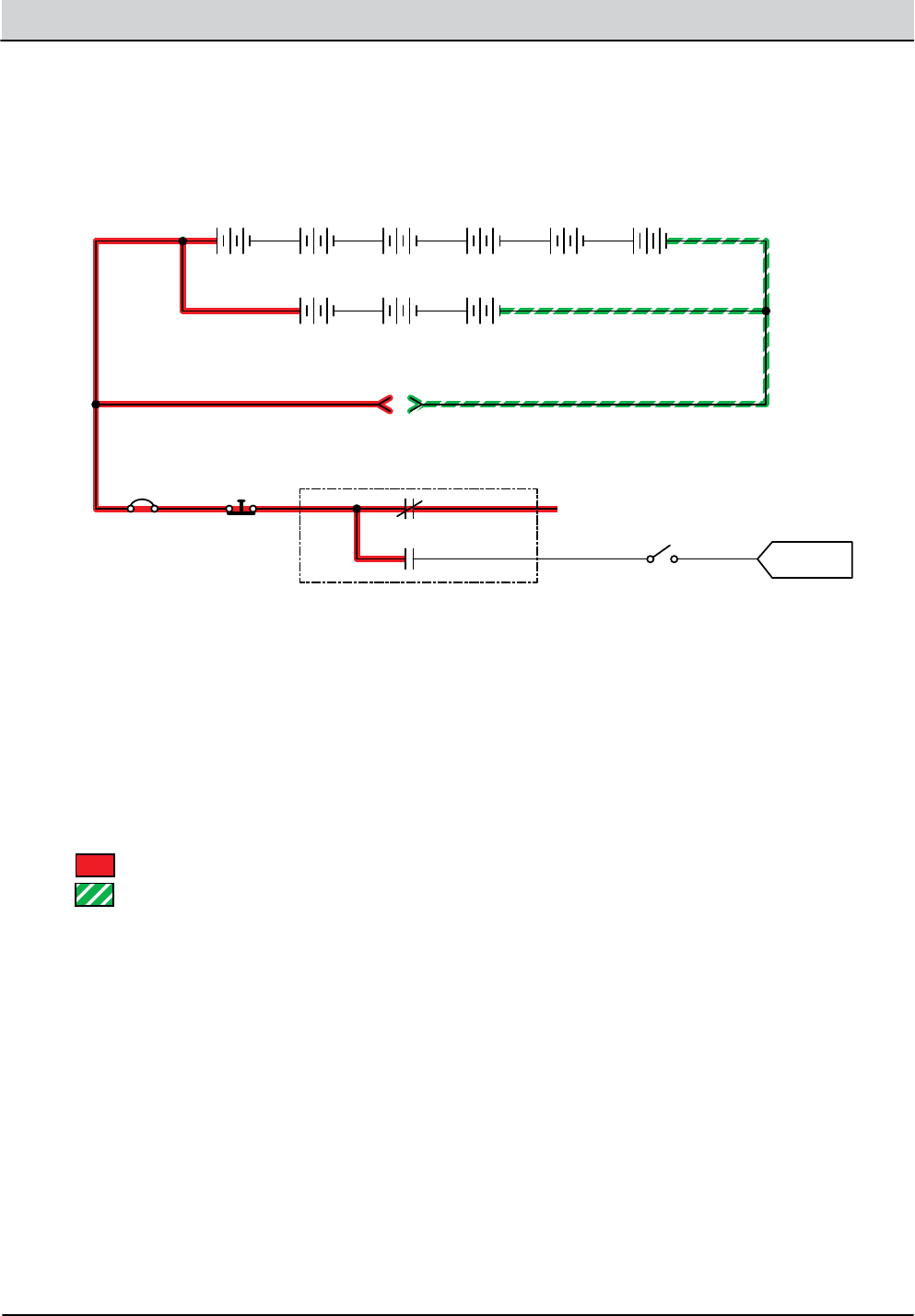
TROUBLESHOOTING
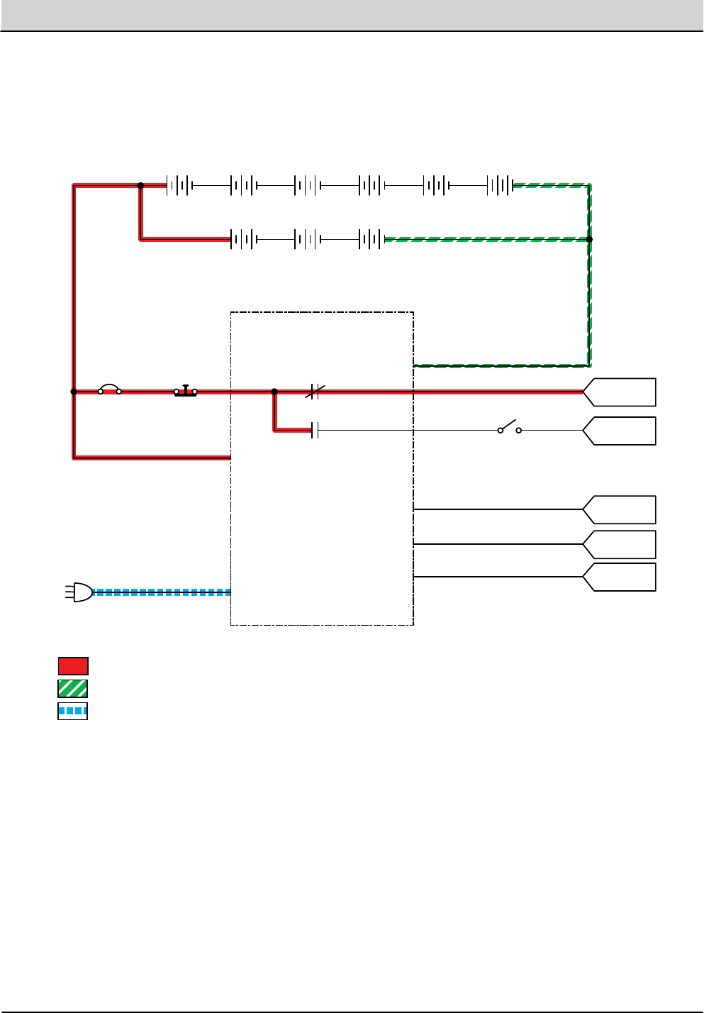
AC Power Cord
RED Cable
BLACK Cable
B5, SG5 Battery Conguration
Onboard Battery Charger
B7, SG7 Battery Conguration
P2-3 P2-4
P2-2
P2-6
CAN +
B +
B -
CAN - P2-10
CAN GROUND
N.O.COM
N.C.
P2-1 113/BLK/WHT
GRN
YEL
5/GRN
7/PUR
3/ORA
4/YEL
1/RED
6/BLU
CB1
2.5A
+ - + - + - + -
+ - + - + -
+ - + -
6 Volt 6 Volt 6 Volt 6 Volt
12 Volt 12 Volt 12 Volt
6 Volt 6 Volt
Hood
Disable
Switch
Key
Switch
Battery Positive +
Battery Negative -
PMC021
AC Volts
J7-9 Interface
Module
J7-10 Interface
Module
CAN-bus +
CAN-bus -
J3-3 Interface
Module
Onboard Battery Charging ON (Optional)

B5/7, SpeedGleam® 5/7 Service Information (1-14) 4-7
TROUBLESHOOTING
Batteries Failed to Charge
sTep AcTion VAlue(s) Yes no
1• Key On
• Is there a blinking BDI fault present?
See “BDI
Faults” in the
Troubleshoot-
ing section of
this manual
Go to Step #2
2• Key O
• Check AC power supply
• Is the rated AC supply voltage present?
Go to Step #3 Check AC
Supply Circuit
Protection
3• See BATTERY CHARGER SETTINGS in the SERVICE
section of this manual and conrm proper charger
settings
• Is the onboard charger set properly?
Go to Step #4 Reprogram
battery char-
ger
4• Key O
• Inspect battery and charger cables for damage, cor-
rosion, contamination or terminal problems
• Do any of the above conditions exist?
Repair or Re-
place Battery
and/or Char-
ger Cables
Go to Step #5
5• Skip this step for sealed or AGM batteries
• Key O
• Disconnect batteries
• Check water level of all battery cells
• Are the lead plates submerged?
Go to Step #6 Add Distilled
Water Until
Lead Plates are
Covered.
6• Key O
• Load test all batteries (AGM or Lead-Acid)
• -or-
• Test specic gravity of each cell using a hydrometer
or refractometer (Lead-Acid)
• Do the batteries pass a load test or are all battery
cells within 0.050 (50 points) specic gravity of each
other?
Replace Bat-
tery Charger
Replace
Battery or Bat-
teries
Terms:
AC = Alternating Current
AGM = Absorbed Glass Mat
Specic Gravity = Relative density of a substance compared to water (1.000 specic gravity)
4-8 B5/7, SpeedGleam® 5/7 Service Information (1-14)
TROUBLESHOOTING
B5, SG5 Battery Conguration
Battery Charger Connector
Battery Charger
Interlock Switch
B7, SG7 Battery Conguration
N.O.COM
N.C.
CB1
2.5A
+ - + - + - + -
+ - + - + -
+ - + -
6 Volt 6 Volt 6 Volt 6 Volt
12 Volt 12 Volt 12 Volt
6 Volt 6 Volt
Hood
Disable
Switch
Not Used
Key
Switch
Battery Positive +
Battery Negative -
PMC021
J7-10 Interface
Module
1/RED
3/ORA
4/YEL
5/GRN 6/BLU
O Board Battery Charging ON

B5/7, SpeedGleam® 5/7 Service Information (1-14) 4-9
TROUBLESHOOTING
Batteries Failed to Charge
sTep AcTion VAlue(s) Yes no
1• Key O
• Check AC power supply
• Is the rated AC supply voltage present?
Go to Step #2 Check AC
Supply Circuit
Protection
2• Key O
• Inspect battery and charger cables for damage, cor-
rosion, contamination or terminal problems
• Do any of the above conditions exist?
Repair or Re-
place Battery
and/or Char-
ger Cables
Go to Step #3
3• Skip this step for sealed or AGM batteries
• Key O
• Disconnect batteries
• Check water level of all battery cells
• Are the lead plates submerged?
Go to Step #4 Add Distilled
Water Until
Lead Plates are
Covered.
4• Key O
• Load test all batteries (AGM or Lead-Acid)
• -or-
• Test specic gravity of each cell using a hydrometer
or refractometer ((Lead-Acid)
• Do the batteries pass a load test or are all battery
cells within 0.050 (50 points) specic gravity of each
other?
Replace Bat-
tery Charger
Replace
Battery or Bat-
teries
Terms:
AC = Alternating Current
AGM = Absorbed Glass Mat
Specic Gravity = Relative density of a substance compared to water (water = 1.000 specic gravity)
4-10 B5/7, SpeedGleam® 5/7 Service Information (1-14)
TROUBLESHOOTING
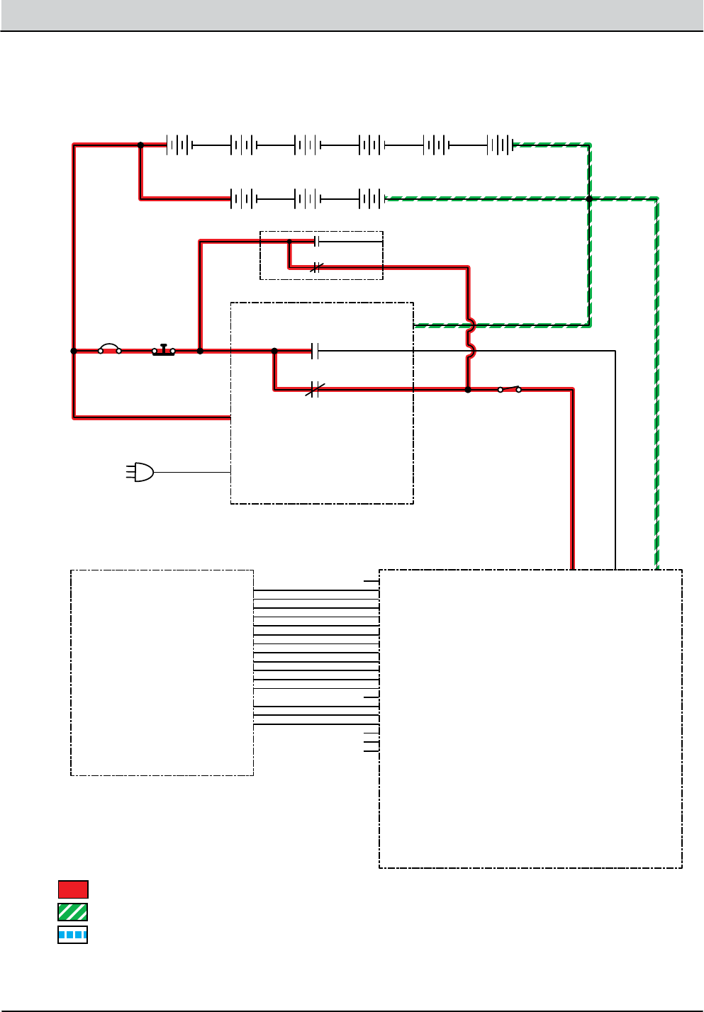
Power-Up ON
AC Power Cord
Ribbon Cable
J9-1 GND_2 (N/U)
J9-2 SPARE_SW2 (N/U)
J9-3 SPARE_SW1 (N/U)
J9-4 DP_INC_SW
J9-5 DP_DEC_SW
J9-6 GND_1
J9-7 SPARE_LED (N/U)
J9-8 DP_1_LED
J9-9 DP_2_LED
J9-10 DP_3_LED
J9-11 IRIS_LED
J9-12 DB_FULL_LED
J9-13 BDI_5_LED
J9-14 BDI_4_LED
J9-15 BDI_3_LED
J9-16 BDI_2_LED
J9-17 BDI_1_LED
J9-18 MTR_HOT_LED
J9-19 SERVICE_LED
J9-20 LED_+5VDC_OUT (N/U)
RED Cable
BLACK Cable
B5, SG5 Battery Conguration
Onboard Battery Charger (Opt)
Interface Module
Operator’s Switch/Light Panel
O-board Battery Charger Interlock Switch (Std)
B7, SG7 Battery Conguration
P2-3 P2-4
P2-2
J7-10 KSI KEY SWITCH INTERLOCK
J7-9 CHARGER INPUT
J7-8 GND
B +
B -
N.O.COM
N.C.
5/GRN
7/PUR
13/BLK
3/ORA
4/YEL
1/RED
6/BLU
CB1
2.5A
+ - + - + - + -
+ - + - + -
+ - + -
6 Volt 6 Volt 6 Volt 6 Volt
12 Volt 12 Volt 12 Volt
6 Volt 6 Volt
Hood
Disable
Switch
Key
Switch
Battery Positive +
Battery Negative -
PMC021 AC Volts
N.O.COM
N.C.
5/GRN

B5/7, SpeedGleam® 5/7 Service Information (1-14) 4-11
TROUBLESHOOTING
Machine Failed to Power Up
sTep AcTion VAlue(s) Yes no
1• Key On
• Test the total battery voltage using a voltmeter
• Is the total battery voltage greater than 30 VDC?
Go to Step #2 Recharge
Batteries and
Test Power-Up
Circuit Opera-
tion
2• Key O
• Firmly press circuit breaker #1 to reset
• Is circuit breaker #1 tripped?
Reset and Test
Power-Up Cir-
cuit Operation
Go to Step #3
3• Key On
• Test voltage applied to the power-up subsystem as
shown on the electrical schematic
• Are the electrical circuits operating as shown on the
electrical schematic?
Go Back to
Step #1
Identify Volt-
age Drop
Location and
Repair or Re-
place Neces-
sary Compo-
nents
Terms:
VDC = DC Voltage
4-12 B5/7, SpeedGleam® 5/7 Service Information (1-14)
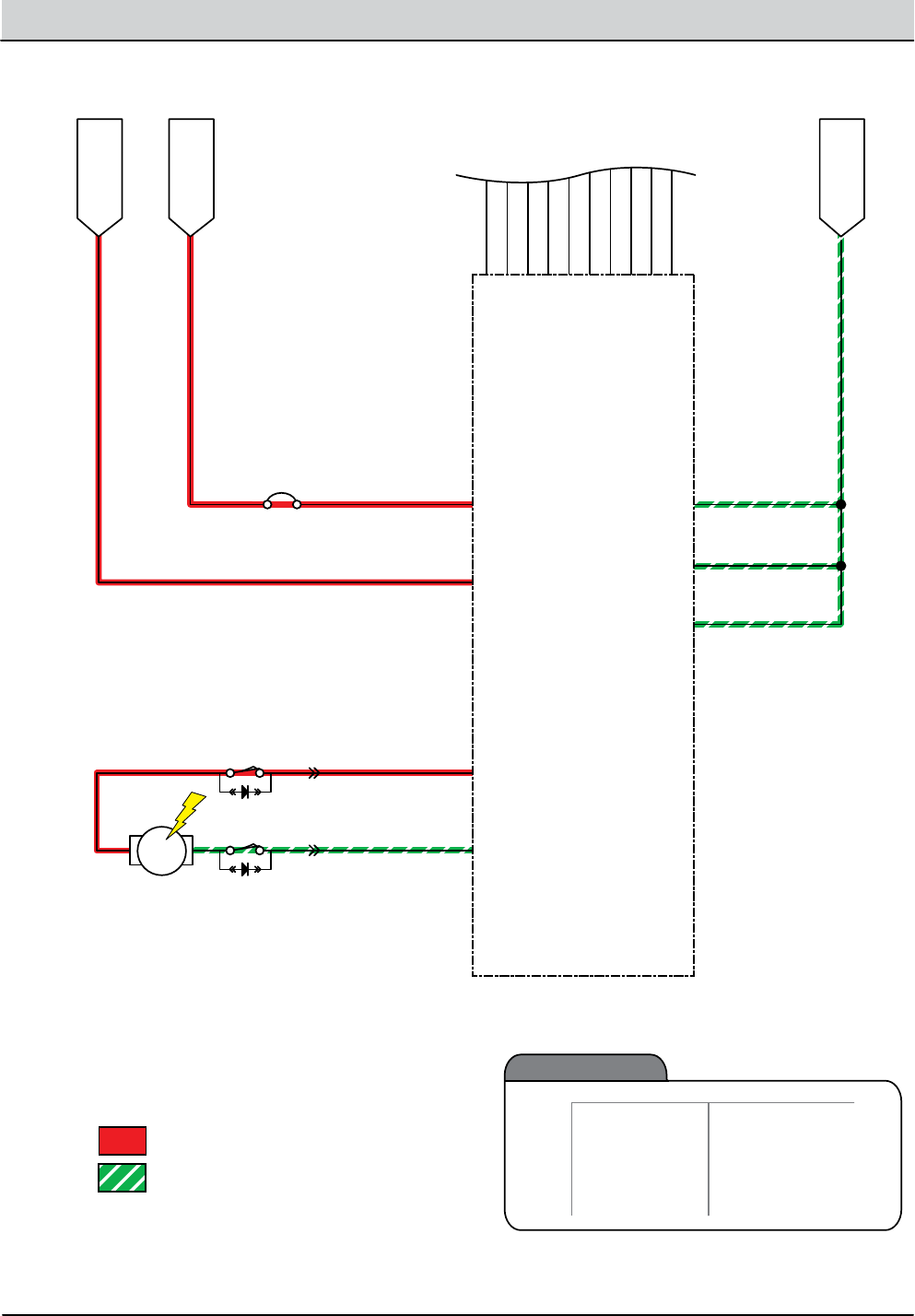
TROUBLESHOOTING
Propel Subsystem (Optional)
J5-1 Base
Controller MTR
B5, SG5 Battery Conguration
I-Drive Propel Module
B7, SG7 Battery Conguration
B+
P1-5 ON/OFF
Enable I-Drive
(B+ from J5-1 = ON)
B-
M1
M2
GND_REF P1-13
REVERSE P1-12
8/GRY
24/YEL 9/WHT
10/TAN
37/PUR
36/BLU
13/BLK
1/RED
CB3
30A
+ - + - + - + -
+ - + - + -
+ - + -
6 Volt 6 Volt 6 Volt 6 Volt
12 Volt 12 Volt 12 Volt
6 Volt 6 Volt
Directional Switch
(closed = reverse)
Propel
Motor
Battery Positive +
Battery Negative -
PMC021
POT_LOW P1-8
SPD_LIMIT P1-9
35/GRN
34/YEL
POT HIGH P1-2
FUSED B+ OUT P1-7
33/ORA
100K Ω Propel
Speed Limit Pot
J12-3 Base
Controller
J5-7 Base
Controller
P1-4 LOW SPEED
P3-4 RX
P3-3 TX
P1-1 WIPER_IN
P3-1 DIGITAL_GND
COMMUNICATION CABLE
TO INTERFACE MODULE
(SHIELDED)
Enable Burnish
(Ground = Low Speed)
27/PUR
BLACK
RED
NATURAL
SHIELD/GRN
11/PNK
STATUS P1-10 J5-5 Base
Controller
12/BRN
AUX2_OUT P1-3 J5-3 Base
Controller
14/YEL
AUX3_OUT P1-11 J5-4 Base
Controller
26/BLU
Propel
(Optional
on B/SG5)
Enabled
• Burnish head down
• Burnish bail
activated
Disabled
Operational Matrix:
• Battery Charger ON Interlock
• Neutral - Ready State
• Low Battery Voltage
(< 30.0 vDC)
• Load Current Fault
• Access Cover Open

B5/7, SpeedGleam® 5/7 Service Information (1-14) 4-13
TROUBLESHOOTING
Machine Failed to Propel
sTep AcTion VAlue(s) Yes no
1• Key On
• Enable propel
• Is there a blinking BDI (Battery Discharge Indicator)
fault present?
See “BDI
Faults” in the
Troubleshoot-
ing section of
this manual
Go to Step #2
2• See SOFTWARE CONFIGURATION TOOL in the SER
VICE section of this manual and conrm the software
is properly congured to enable the propel feature
• Is the software congured properly?
Go to Step #3 Reprogram
software
3• Key O
• Place machine on blocks so drive wheels are lifted o
the oor
• Enable forward propel
• Test voltage applied to the propel subsystem as
shown on the electrical schematic
• Are the electrical circuits operating as shown on the
electrical schematic?
Go Back to
Step #1
Identify Volt-
age Drop
Location and
Repair or Re-
place Neces-
sary Compo-
nents
Terms:
BDI = Battery Discharge Indicator
4-14 B5/7, SpeedGleam® 5/7 Service Information (1-14)
TROUBLESHOOTING
Battery Positive +
Battery Negative -
PMC011
MTR
Lift Actuator
(1-3 Amps)
RIBBON CABLE TO
HALF-BRIDGE MODULE
BASE CONTROLLER
MODULE
B+
KSI
(KEY SWITCH INTERLOCK)
ACT_1
ACT_2
GND_POWER_A
GND_POWER_B
GND_RETURN
SPARE_1
SPARE_2
ENABLE
PWM
OVER_I
I_PEAK
I_SET
+12V
+5V
B+_MONITOR
J1-19
J1-17
J1-15
J1-13
J1-11
J1-9
J1-7
J1-5
J1-3
J1-1
Unswitched B+
Battery (-)
Ground
1/RED
Switched B+ 6/BLU
6/BLU
16/BLU
J12-1
J10-1
J12-5
J12-6
J12-7
J12-8
J5-10
13/BLK
13/BLK
13/BLK
22/BRN
EXTEND
LIMIT SW.
RETRACT
LIMIT SW. 23/ORA
CB2
15A
Lift
Actuator
(Option)
Enabled
• Burnish head down
• Burnish bail activated
Disabled
Operational Matrix:
• Burnish Head Up
• Burnish Bail Release
• Low Battery Voltage(< 32.5 V)
• Load Current Fault
• Battery Charger ON Interlock
• Access Cover Open
• High Motor Temp
Burnish Head Lift Actuator (Optional)

B5/7, SpeedGleam® 5/7 Service Information (1-14) 4-15
TROUBLESHOOTING
Burnish Head Failed to Raise/Lower
sTep AcTion VAlue(s) Yes no
1• Key On
• Enable burnish motor
• Is there a blinking BDI (Battery Discharge Indicator)
fault present?
See “BDI
Faults” in the
Troubleshoot-
ing section of
this manual
Go to Step #2
2• See SOFTWARE CONFIGURATION TOOL in the SER
VICE section of this manual and conrm the software
is properly congured to enable the automated
down pressure feature
• Is the software congured properly?
Go to Step #3 Reprogram
software
3• Key O
• Enable burnish motor
• Test voltage applied to the actuator subsystem as
shown on the electrical schematic
• Are the electrical circuits operating as shown on the
electrical schematic?
Go Back to
Step #1
Identify Volt-
age Drop
Location and
Repair or Re-
place Neces-
sary Compo-
nents
Terms:
BDI = Battery Discharge Indicator
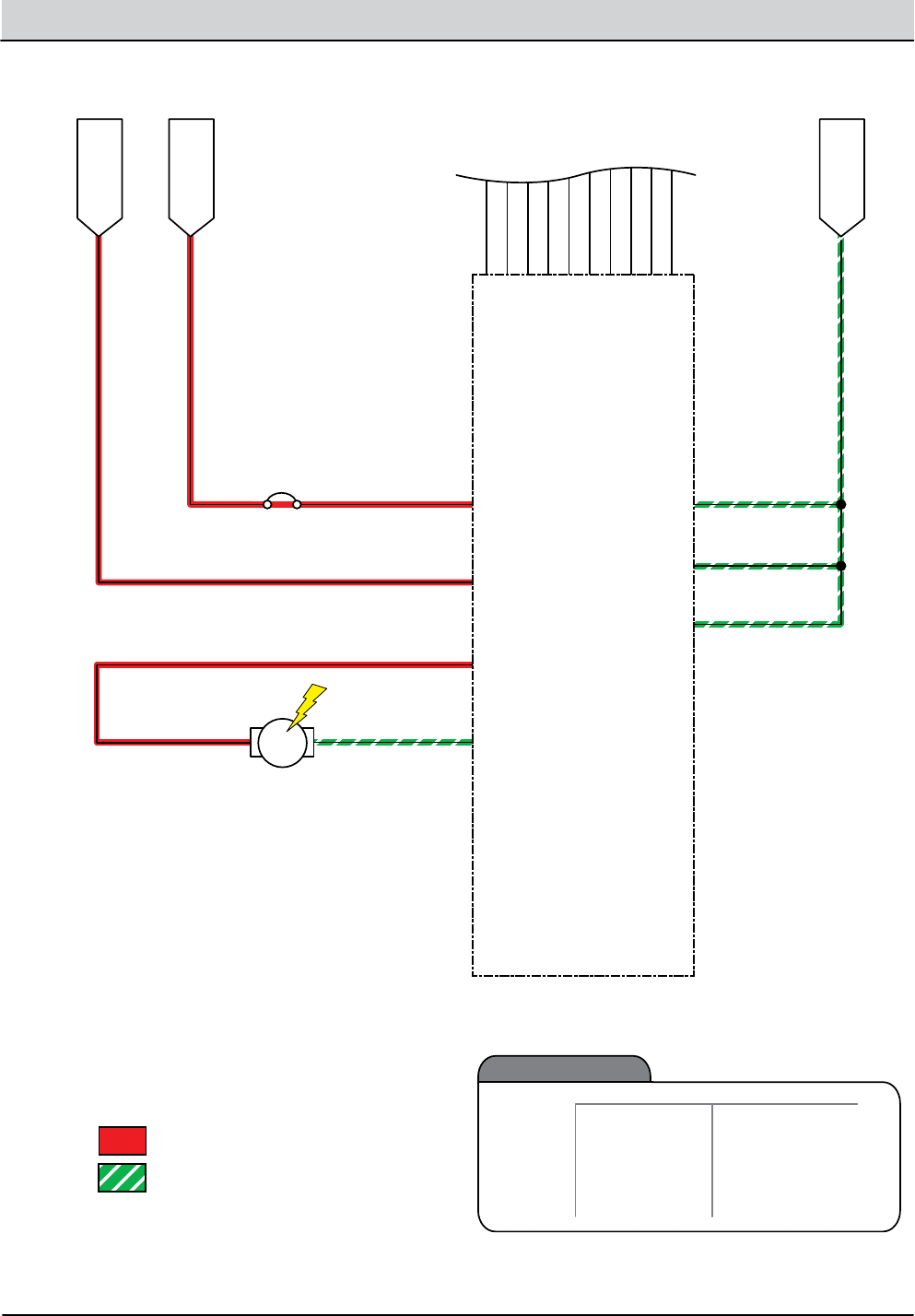
4-16 B5/7, SpeedGleam® 5/7 Service Information (1-14)
TROUBLESHOOTING
Vacuum Fan ON (Optional)
Battery Positive +
Battery Negative -
PMC011
MTR
Vacuum Motor
(5 Amps)
RIBBON CABLE TO
HALF-BRIDGE MODULE
BASE CONTROLLER
MODULE
B+
KSI
(KEY SWITCH INTERLOCK)
B+
VAC
GND_POWER_A
GND_POWER_B
GND_RETURN
SPARE_1
SPARE_2
ENABLE
PWM
OVER_I
I_PEAK
I_SET
+12V
+5V
B+_MONITOR
J1-19
J1-17
J1-15
J1-13
J1-11
J1-9
J1-7
J1-5
J1-3
J1-1
Unswitched B+
Battery (-)
Ground
1/RED
Switched B+ 6/BLU
6/BLU
16/BLU
J12-1
J10-1
J12-2
J12-4
J12-7
J12-8
J5-10
13/BLK
13/BLK
13/BLK
19/WHT
25/GRN
CB2
15A
Vacuum Fan
(Optional)
Enabled
• Burnish head down
• Burnish bail activated
Disabled
Operational Matrix:
• Burnish Head Up
• Burnish Bail Release
• Low Battery Voltage(< 32.5 V)
• Load Current Fault
• Battery Charger ON Interlock
• Access Cover Open
• High Motor Temp

B5/7, SpeedGleam® 5/7 Service Information (1-14) 4-17
TROUBLESHOOTING
Vacuum Fan Failed to Turn ON (Optional)
sTep AcTion VAlue(s) Yes no
1• Key On
• Enable vacuum fan
• Is there a blinking BDI (Battery Discharge Indicator)
fault present?
See “BDI
Faults” in the
Troubleshoot-
ing section of
this manual
Go to Step #2
2• See SOFTWARE CONFIGURATION TOOL in the SER
VICE section of this manual and conrm the software
is properly congured to enable the vacuum fan
feature
• Is the software congured properly?
Go to Step #3 Reprogram
software
3• Key O
• Enable vacuum fan
• Test voltage applied to the vacuum fan subsystem as
shown on the electrical schematic
• Are the electrical circuits operating as shown on the
electrical schematic?
Go Back to
Step #1
Identify Volt-
age Drop
Location and
Repair or Re-
place Neces-
sary Compo-
nents
Terms:
BDI = Battery Discharge Indicator

4-18 B5/7, SpeedGleam® 5/7 Service Information (1-14)
TROUBLESHOOTING

SERVICE
SECTION 5
5-1
B5/7, SpeedGleam® 5/7 Service Information (1-14)
SERVICE
SOFTWARE CONFIGURATION TOOL ........ 52
CONNECTING TO THE INTERFACE
MODULE ............................ 52
MACHINE CONFIGURATION
SOFTWARE .......................... 53
BATTERY CHARGER SETTING ............... 54
PAD PRESSURE SETTING ................... 55
BURNISH MOTOR .......................... 56
VACUUM FAN .............................. 58
CONTROL MODULES .......................59
ONBOARD BATTERY CHARGER ............511
INTERFACE MODULE ......................512
BAIL SWITCH OR POTENTIOMETER ........513
Contents Page
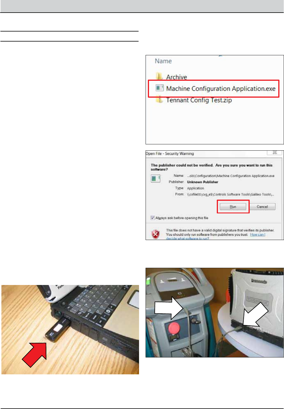
5-2 B5/7, SpeedGleam® 5/7 Service Information (1-14)
SERVICE
Interface Module:
Base Module:
Half-Bridge Module:
i-Drive Module:
Onboard Battery Charger Module
Machine software must be recongured if the i-Drive or
interface modules are replaced in the eld or optional fea-
tures are installed in the eld. The tool consists of propri-
etary software installed on a notebook computer. A USB
cable connects from the notebook to an external port on
the control console. The software conguration tool con-
gures up to ve control modules depending on options
installed. The interface module stores conguration data
and communicates via RS232 communication with the
i-Drive and through a CAN-Bus to all other modules.
SOFTWARE CONFIGURATION TOOL
CONNECTING TO THE INTERFACE MODULE
Windows7 OS, Microsoft .NET
4.0
Install a ash drive containing the application soft-
ware into a USB port on a notebook computer.
1.
Launch the software by double clicking the ash
drive le “Machine Conguration Application.exe”
and then click “Run.”
2.
Connect a USB cable from a notebook computer to
the machine and turn the key switch On.
3.
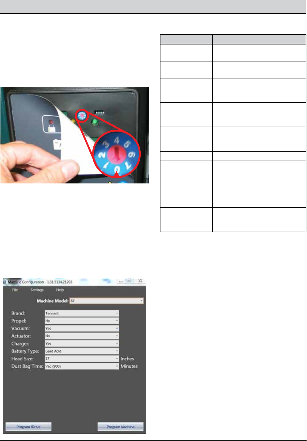
B5/7, SpeedGleam® 5/7 Service Information (1-14) 5-3
SERVICE
MACHINE CONFIGURATION SOFTWARE
Select the desired conguration for the burnisher
model and then click on or
Program iDrive should only be clicked if
the iDrive module has been replaced. Program Ma-
chine should only be clicked if the interface module
has been replaced or if aftermarket options have
changed (e.g. batteries changed from lead-acid to
sealed).
1.
Cycle the key switch to save the changes 2.
FEATURE DESCRIPTION
Model Changes model-specic features
and software listed below:
Drive Type Enables self-propel or pad-assist
drive
Dust Control Enables passive dust control (no
vacuum fan) or active dust control
(vacuum fan).
Down Pressure Enables automated down pres-
sure (lift actuaor) or mechanical
(no actuator)
Charger Location Enables either on-board or o-
board battery charger program-
ming
Head Size - 20” or 27”
Dust Bag Time Sets the dust bag maintenance
timer for passive dust control (no
vacuum fan) or active dust control
(vacuum fan). The time interval
changes with regards to model
and active/passive settings.
Battery Pack Enables an onboard charging pro-
le for wet, AGM, or no batteries
as well as the BDI discharge curve.
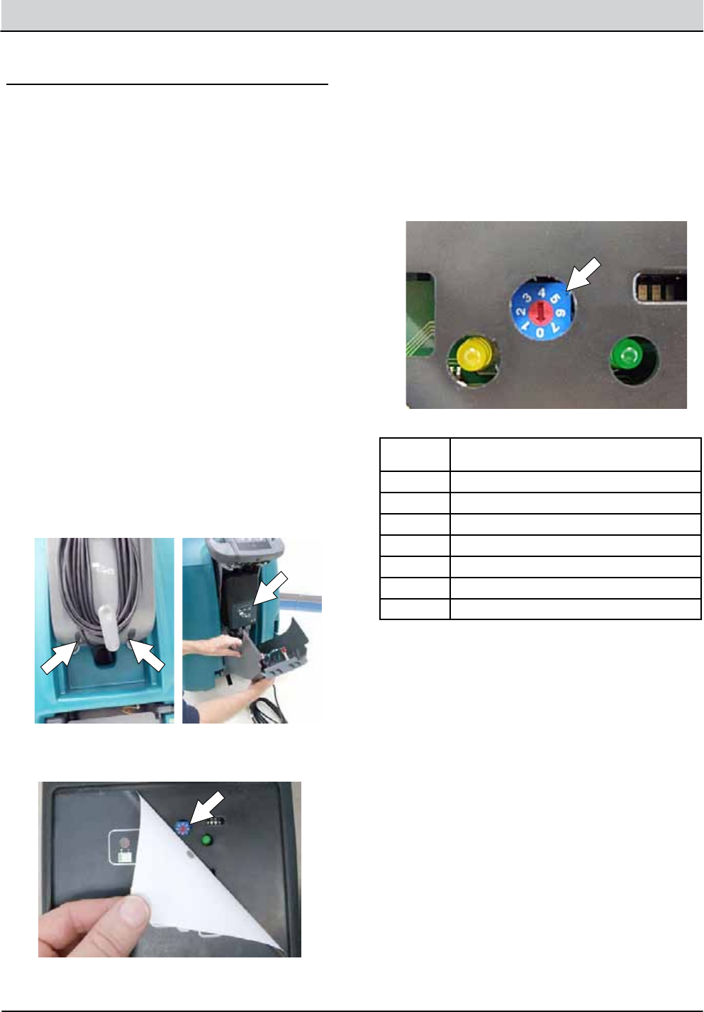
5-4 B5/7, SpeedGleam® 5/7 Service Information (1-14)
SERVICE
4. Usingasmall standard screwdriver, turn the dial to
the appropriate battery type according to the
following chart (Figure 34).
NOTE: The “0” position is only used when machine is
programmed at the factory or when the Software
Installation kit is used. Once the setting is changed from
“0”, it shouldnot be changedback to “0” unless machine
is reprogrammed with the software installation kit
otherwise battery damage may result.
FIG. 34
Dial
Position BatteryDescription Settings
0Factory and Software Kit Setting
1Wet, Trojan180- 250 AH
2Wet, Trojan260- 360 AH
3Wet, Enersys 200- 350 AH
4AGM, Discover 200- 300 AH
5AGM, Fullriver 200- 350 AH
6Gel, Sonnenschein150- 250 AH
4. Re- apply the displaylabel.
5. Replace the control console.
6. To set the BDI to the newbattery type,plug the
on- board battery charger cord into an electrical
outlet.
BATTERY CHARGER SETTINGS
The battery charger is set to charge the battery type
suppliedwith your machine. If you choose to change to
adifferentbattery type or capacity, the battery charger
and the machine’s battery discharge indicator (BDI)
must be reprogrammed to preventbattery damage.
To have machine reprogrammed, contact service or
order the Software Installation Kit (p/n 9012788).
For modelsequippedwith the on- board charger, as an
alternative to having the machine reprogrammed, the
on- board battery charger settings can be manually
changed. Once the on- board charger settings are
properly changed as described in the following
instructions, the machine’s software willautomatically
reprogram the BDI to the newbattery type.
For machine’s equippedwith an off- board battery
changer, the Reprogramming Kit is required to change
the BDI setting. After the BDI is reprogrammed, refer to
the off- board charger’s owner manual to change
charging profile settings.
To Change the On- BoardBattery Charger Settings:
1. Unwrap the battery chargerpower cord from the
cord hooks.
2. UsingaT25 star screwdriver, remove the two
screwslocated at the bottom of the control console
to access battery charger (Figure 32).
FIG. 32
3. Carefullypeel up the chargerdisplaylabel to
access the dial settings (Figure 33).

B5/7, SpeedGleam® 5/7 Service Information (1-14) 5-5
SERVICE
PAD PRESSURE SETTING (Models equipped with
mechanical pad pressure adjustment)
For modelsequippedwith mechanical pad pressure
adjustment, the pad pressure is factory set at the
optimal setting. Many variables come in to play to
achievingoptimal burnishingperformance; floor type,
floor finish, floor conditionandpad type.
To confirm that the factory settingbest meets your
burnishingapplication, it’s recommended to perform the
following procedure. Once the pad pressure is properly
set for yourburnishingapplication, thiswill provide
consistentperformance for your routineburnishing
schedule. This is referred to as the “Set and Forget”
method.
1. To activate the pad pressure mode,locate the
hiddenbutton (smallindent) on the left side of the
control panel (Figure 7).
2. Press andhold the hiddenbutton and turn the key
on.Hold the button untilasingle greenlightappears
at the battery discharge indicator (Figure 7). When
the button is released, the greenlightwill turn off and
the service indicator symbolwill turn on.
The machine is now ready to verify the currentpad
pressure.
FIG. 7
3. Pull the start bailandbeginburnishing for a
minimum of 10 seconds (Figure 8). The LED’s will
ripple thenasinglelightwillappear confirming the
currentpad pressure setting. See the following
chart for down pressure settings.
FIG. 8
LED Codef=On Down Pressure Setting
fFFFFFlashing - Too Low
fFFFFLow
FfFFFMediumLow
FFfFFMedium
FFFfFMediumHigh
FFFFfHigh
FFFFfFlashing - Too High
The mediumdown pressure setting is recommended.
Determine the burnishingperformance at this setting
andadjust as necessary.
To adjust pressure setting proceed to the next step.
4. Raise the burnishingheadand remove key. Locate
the pad pressure adjustment cotter pin (Figure 9).
FIG. 9
5. To increase down pressure, move the cotter pin to
the next hole towards the motor. To decrease the
down pressure move the cotter pininopposite
direction (Figure 10).
FIG. 10
6. Repeat steps 1- 3 andadjust the pinuntil desired
down pressure is achieved.
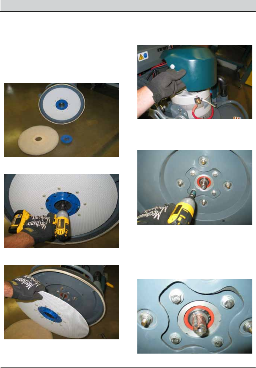
5-6 B5/7, SpeedGleam® 5/7 Service Information (1-14)
SERVICE
REMOVING BURNISH MOTOR
INSTALLING BURNISH MOTOR
2.
1.
1.
3.
4.
5.
6.
7.
Remove burnish pad.
Key O and disconnect batteries.
Installation is the reverse of removal. Be sure to apply
anti-sieze to the motor shaft before reassembly.
Remove burnish pad driver mounting hardware (1).
Remove burnish pad driver from head assembly.
Tilt burnish head down, release the plastic fasteners
and remove motor cover.
Disconnect electrical cables from burnish motor.
Tilt head up and remove (4) motor mounting bolts.
FOR SAFETY: Before leaving or servicing machine, stop
on level surface, turn o machine, remove key and
disconnect batteries.
FOR SAFETY: Before leaving or servicing machine, stop
on level surface, turn o machine, remove key and
disconnect batteries.
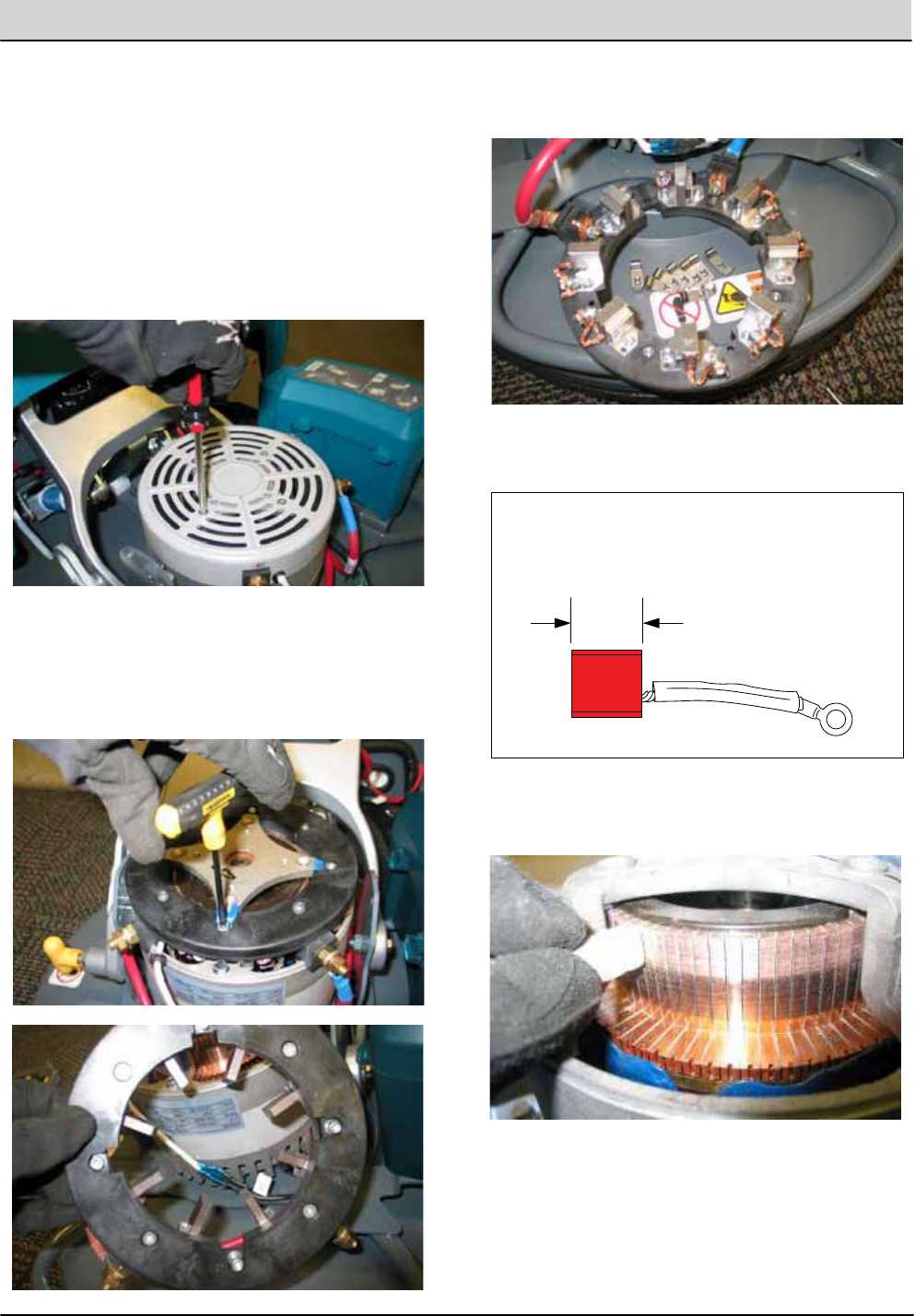
B5/7, SpeedGleam® 5/7 Service Information (1-14) 5-7
SERVICE
CARBON BRUSHES
1.
2.
3.
4.
5.
6.
Key O and disconnect batteries.
Remove upper motor cover mounting hardware and
and set cover aside.
Remove brush holder ring mounting hardware (4)
and brush mounting ring (1).
Remove brush tensioner springs (8).
Inspect and replace carbon brushes if they are less
than 10mm (0.375 in).
Clean the commutator using a stone and then use
compressed air to clean any dust from inside the
motor.
FOR SAFETY: Before leaving or servicing machine, stop
on level surface, turn o machine, remove key and
disconnect batteries.
MBM002
10mm (0.375 in)
Carbon Brush Wear Limit:
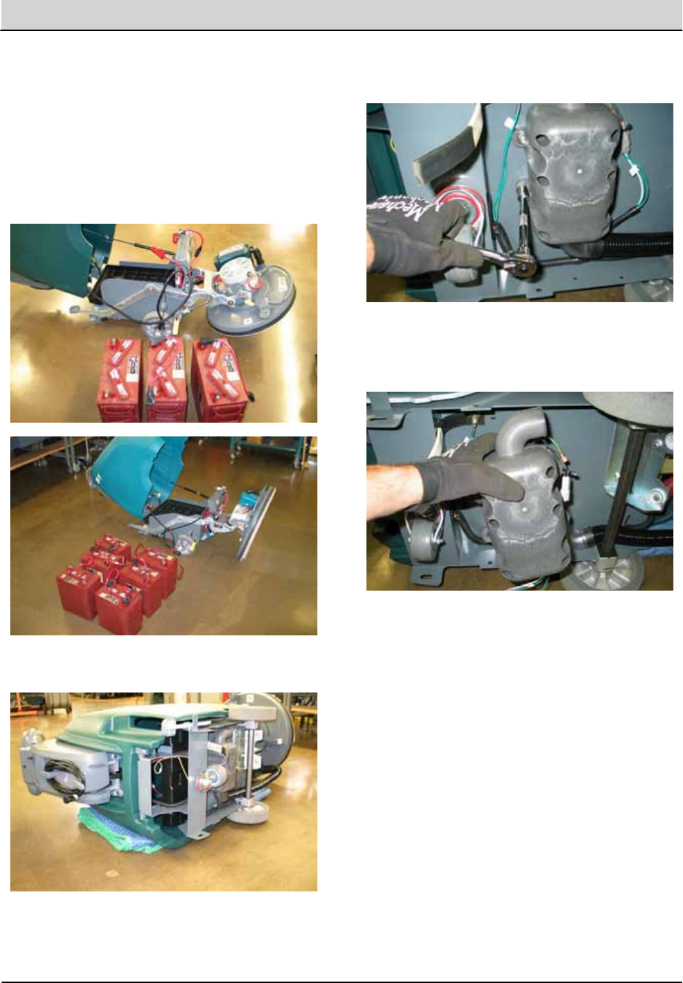
5-8 B5/7, SpeedGleam® 5/7 Service Information (1-14)
SERVICE
REMOVING VACUUM FAN
INSTALLING VACUUM MOTOR
2.
1.
1.
3.
5.
6.
7.
Open access cover and remove batteries.
Key O and disconnect batteries.
Installation is the reverse of removal.
Carefully tip the machine onto a protective blanket to
avoid damage to the side of the burnisher.
Remove vacuum fan mounting hardware (4).
Disconnect vacuum fan from wire harness.
Remove vacuum fan assembly.
FOR SAFETY: Before leaving or servicing machine, stop
on level surface, turn o machine, remove key and
disconnect batteries.
FOR SAFETY: Before leaving or servicing machine, stop
on level surface, turn o machine, remove key and
disconnect batteries.
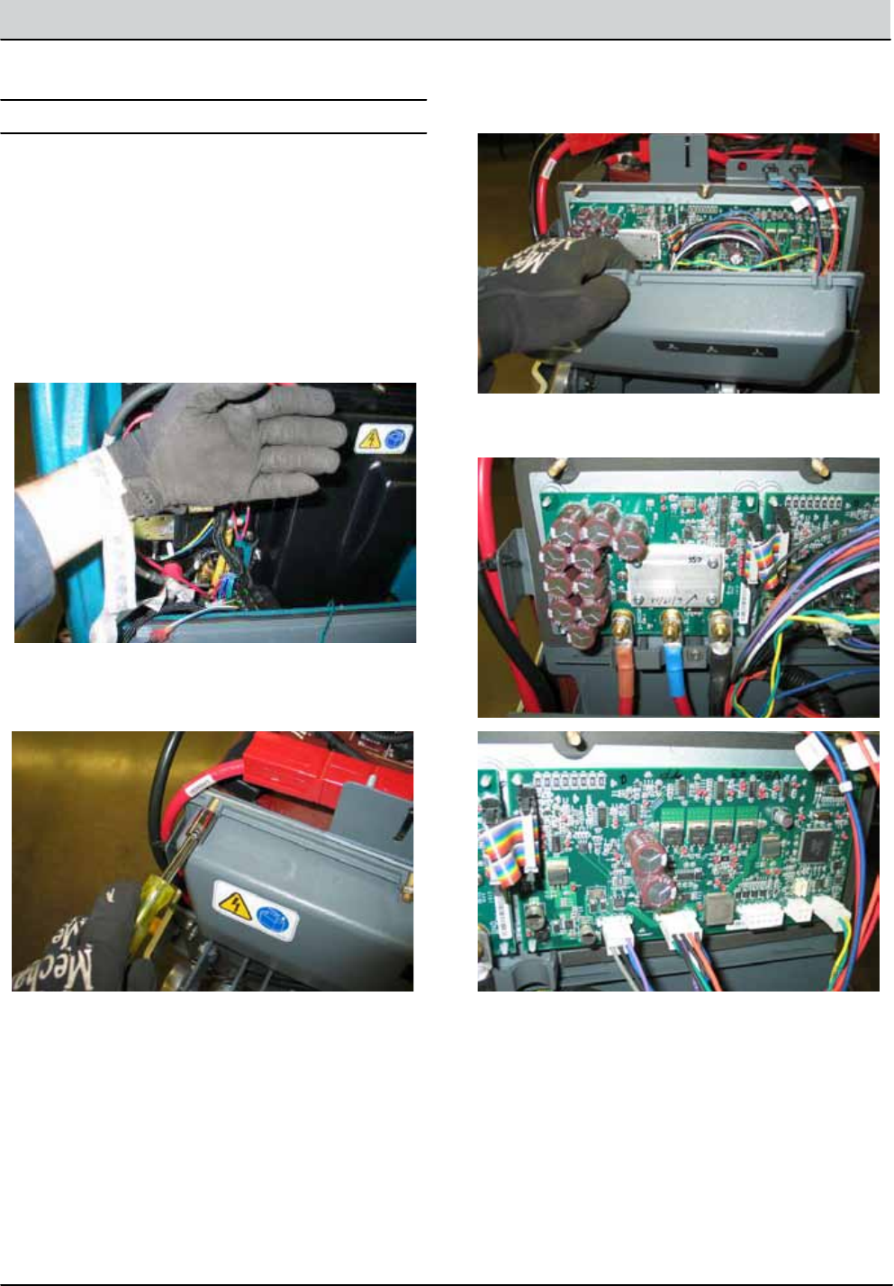
B5/7, SpeedGleam® 5/7 Service Information (1-14) 5-9
SERVICE
CONTROL MODULES
REMOVING HALFBRIDGE/BASE CONTROL MODULES
FOR SAFETY: When servicing machine, disconnect bat-
tery connections before working on machine.
1.
3.
4.
5.
6.
2.
Key O and batteries disconnected.
Remove electrical access panel mounting hardware
(3) and lower access panel.
Remove control module cover.
Disconnect all electrical connections.
Remove modules from machine.
Attach a static wrist strap to the battery (-) terminal
to prevent ESD damage to the modules.
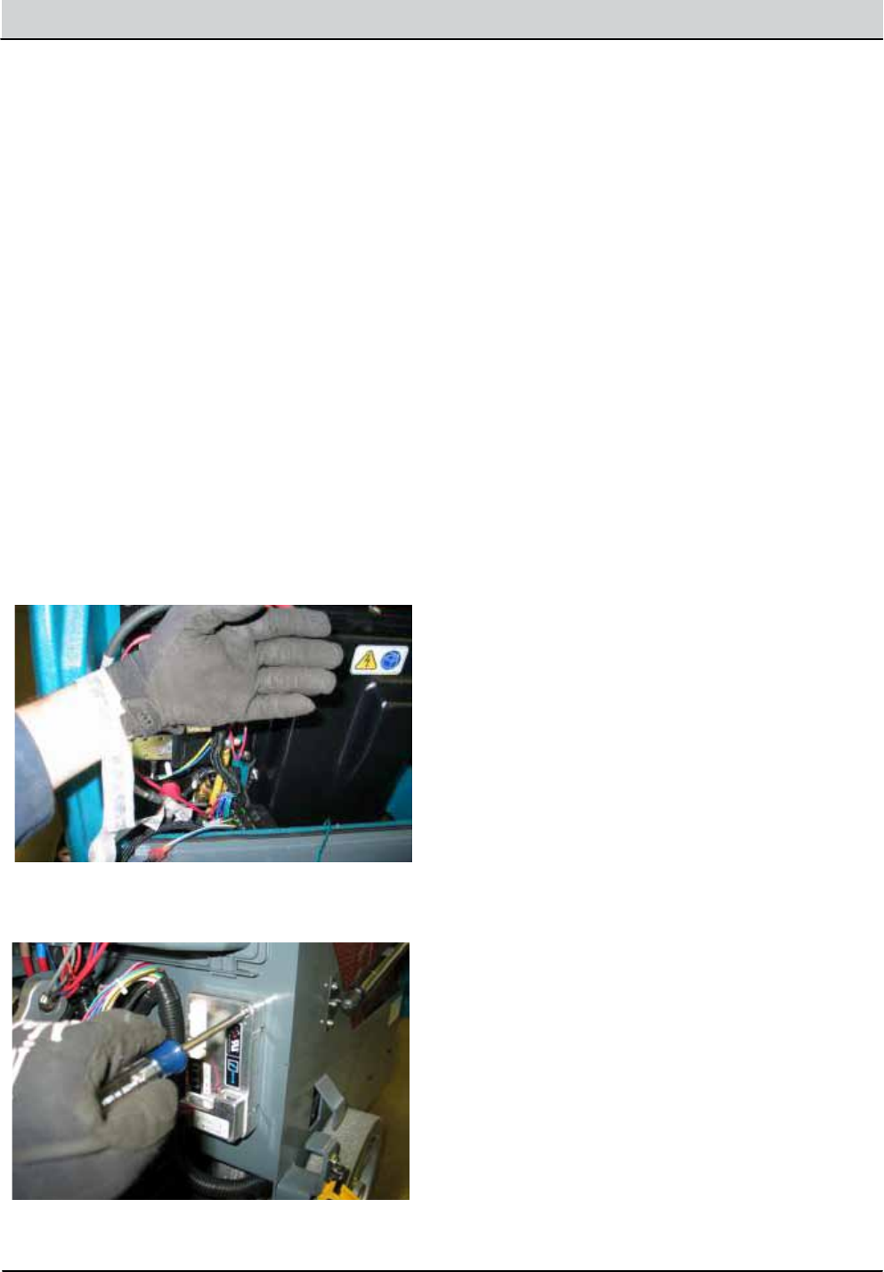
5-10 B5/7, SpeedGleam® 5/7 Service Information (1-14)
SERVICE
INSTALLING HALFBRIDGE/BASE CONTROL MODULE INSTALLING IDRIVE MODULE
FOR SAFETY: When servicing machine, disconnect bat-
tery connections before working on machine.
FOR SAFETY: When servicing machine, disconnect bat-
tery connections before working on machine.
1. 1.
2.
Installation is reverse of removal. Installation is reverse of removal.
The new i-Drive module must be programmed to
operate in the burnisher. See SOFTWARE CONFIGU
RATION TOOL in the SERVICE section of this manual.
REMOVING IDRIVE MODULE
FOR SAFETY: When servicing machine, disconnect bat-
tery connections before working on machine.
1.
3.
2.
Key O and batteries disconnected.
Disconnect electrical connections and remove i-Drive
mounting screws (2).
Attach a static wrist strap to the battery (-) terminal
to prevent ESD damage to the logic board.
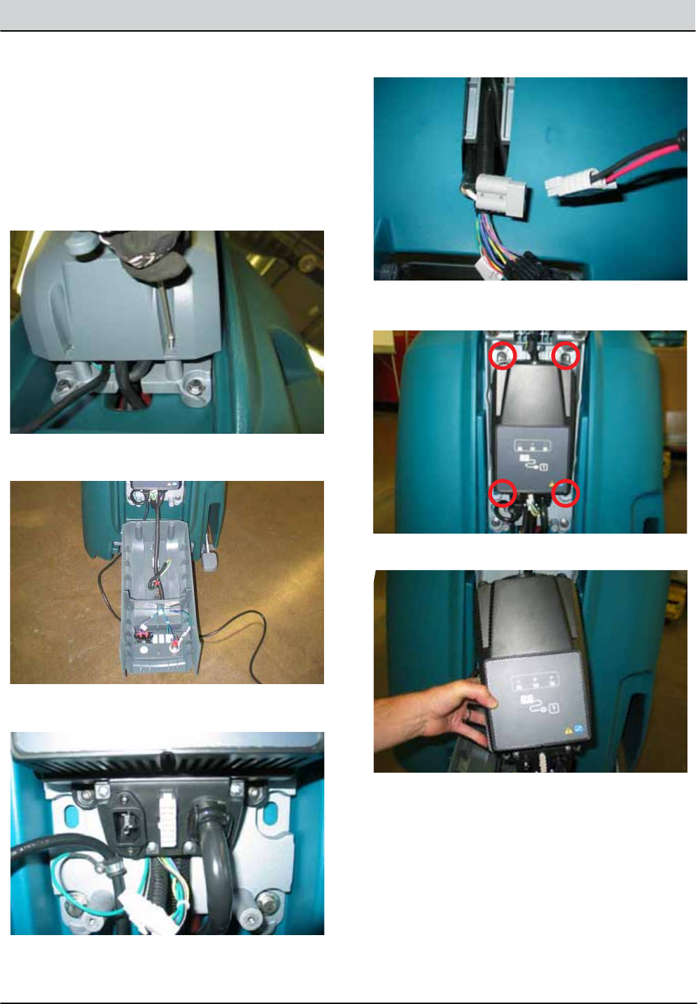
B5/7, SpeedGleam® 5/7 Service Information (1-14) 5-11
SERVICE
REMOVING ONBOARD BATTERY CHARGER
FOR SAFETY: When servicing machine, disconnect bat-
tery connections before working on machine.
1.
2.
Key O and batteries disconnected.
Remove T-25 torx mounting screws (2).
3.
5.
4.
6.
Carefully lower access cover.
Remove battery charger mounting hardware (4).
Disconnect charger electrical connections.
Remove battery charger.
INSTALLING ONBOARD BATTERY CHARGER
FOR SAFETY: When servicing machine, disconnect bat-
tery connections before working on machine.
1. Installation is reverse of removal.
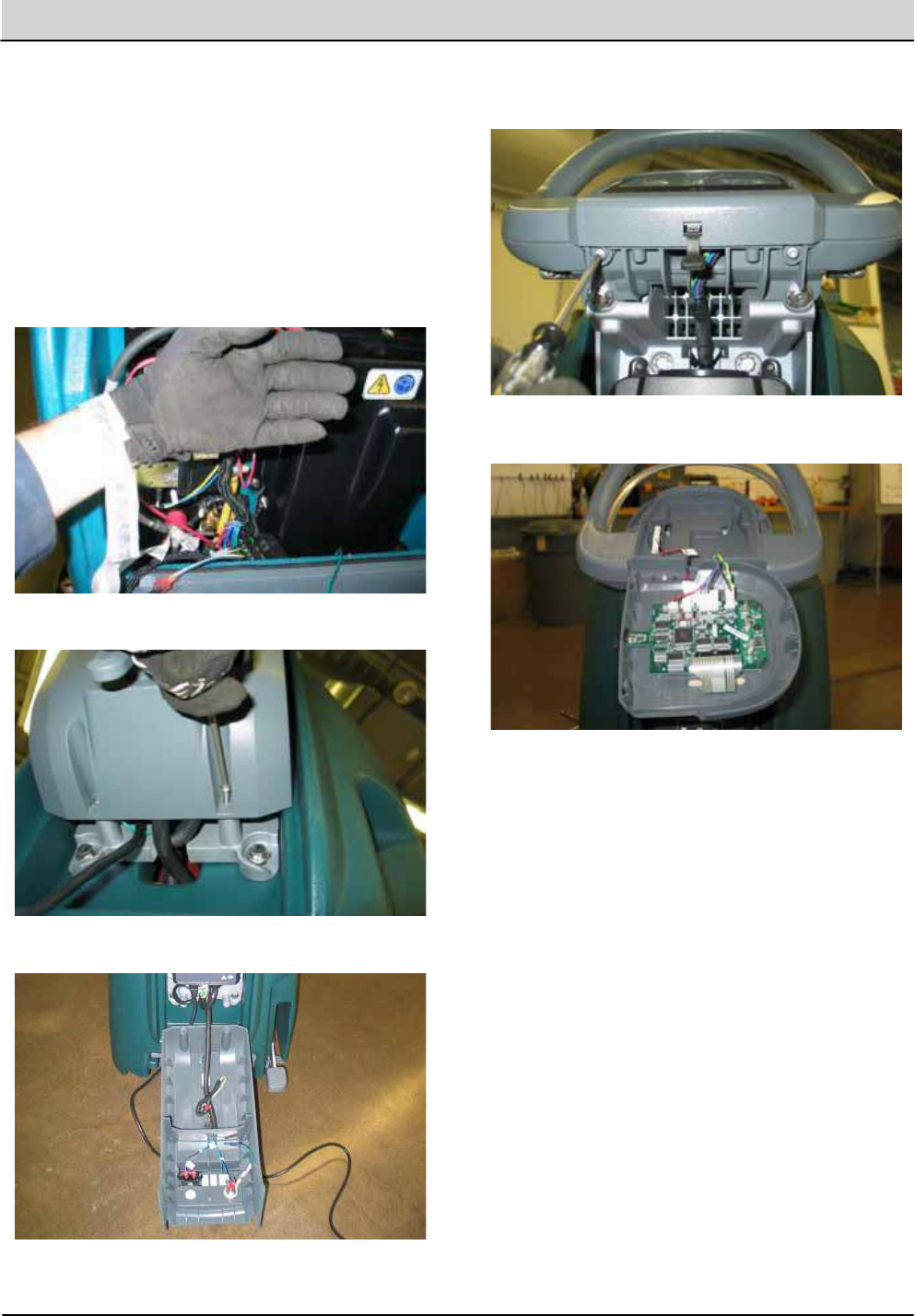
5-12 B5/7, SpeedGleam® 5/7 Service Information (1-14)
SERVICE
INSTALLING INTERFACE MODULE
FOR SAFETY: When servicing machine, disconnect bat-
tery connections before working on machine.
1.
2.
Installation is reverse of removal.
The new interface module must be programmed to
operate in the burnisher. See SOFTWARE CONFIGU
RATION TOOL in the SERVICE section of this manual.
REMOVING INTERFACE MODULE
FOR SAFETY: When servicing machine, disconnect bat-
tery connections before working on machine.
1.
2.
3.
4.
5.
6.
7.
Key O and batteries disconnected.
Attach a static wrist strap to the battery (-) terminal
to prevent ESD damage to the logic board.
Remove T-25 torx mounting screws (2).
Carefully lower access cover.
Remove T-25 torx mounting screws (2).
Lift up on the bottom of the panel and slide down-
ward to remove.
Disconnect electrical connections and remove inter-
face module.
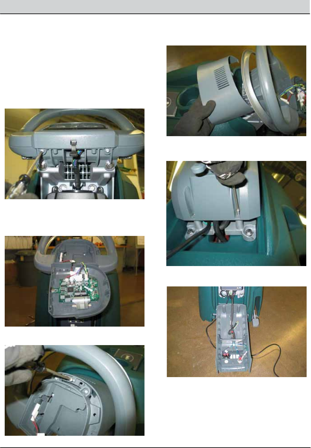
B5/7, SpeedGleam® 5/7 Service Information (1-14) 5-13
SERVICE
REMOVING BAIL SWITCH OR POTENTIOMETER
FOR SAFETY: When servicing machine, disconnect bat-
tery connections before working on machine.
1.
4.
3.
2.
5.
7.
6.
Key O and batteries disconnected.
Remove T-25 torx mounting screws (3).
Carefully separate the touch panel from the console
and disconnect all electrical connections. Set instru-
ment panel aside.
Remove T-25 torx mounting screws (2).
Remove cover and set aside.
Carefully lower access cover.
Remove rear access cover mounting screws (2).
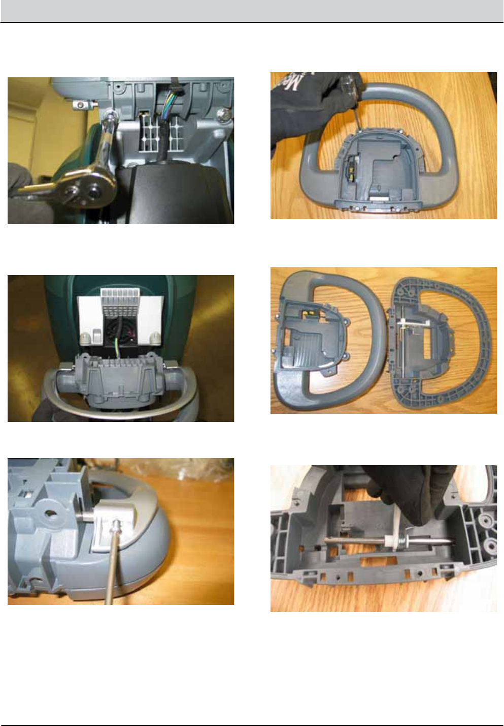
5-14 B5/7, SpeedGleam® 5/7 Service Information (1-14)
SERVICE
INSTALLING NEW BAIL SWITCH OR POTENTIOMETER
1. Installation is reverse of removal.
10.
11.
12.
13.
14.
Remove bail screws (2) and set bail aside.
Remove screws (4) from front of operator’s console.
Remove screws (9) from rear of operator’s console
and separate console assembly.
Release spring, rotate mechanism towards bottom
of operator console, and slide assembly to the side
to remove.
Remove bail switch or throttle poteniometer de-
pending on model.
8.
9.
Remove operator console mounting bolts (2).
Lift up and forward to remove the operator console
and place console on a work bench.
