R14 Service Manual Tennant Rider Carpet Extractor
2018-06-20
: Sweepscrub Tennant-R14-Rider-Carpet-Extractor-Service-Manual tennant-r14-rider-carpet-extractor-service-manual 2778 file product_file
Open the PDF directly: View PDF ![]() .
.
Page Count: 58
- R14 Service Information Manual
- Table of Contents
- Safety Warnings
- MACHINE INFORMATION
- MAINTENANCE
- ELECTRICAL
- Electrical Schematic
- Wire Harness Group
- Seat Harness
- ReadySpace & Extraction Plumbing Diagram
- 35 Pin Connector Detail
- Electrical Symbols & Terms
- Key OFF Power Distribution - Battery Charger not connected
- Key OFF Power Distribution - Battery Charger connected
- Key ON, Operator on Seat
- Tank Level Switches
- Horn & Hour Meter
- Propel Forward System
- Propel Reverse System
- Braking System
- Lower Scrub Head
- Lower Scrub Head & Vacuum Shoes
- Brush Motors
- Vacuum Fan Motors
- Solution Pump & Solenoid Valves (ReadySpace Mode)
- Solution Pump & Solenoid Valves (Extraction Mode)
- Operational Modes & Interlocks
- Diagnostic & Fault Alarms
- Diagnostic & Configuration Modes
- LED Locations & Descriptions
- Display Software Revision Mode
- Self Test Mode
- Input Display Mode
- Manual Mode
- Propel/Brake Diagnostics
- Reverse Alarm Select Mode
- Inputs & Outputs Table
Service Information Manual
R14
Dual Technology Rider Carpet Cleaner
HygenicRFully Cleanable Tanks
More than clean, it’s ReadySpace.R
R
*1032129*
www.tennantco.com
1032129
Rev. 01 (12-2006)
North America
B
A
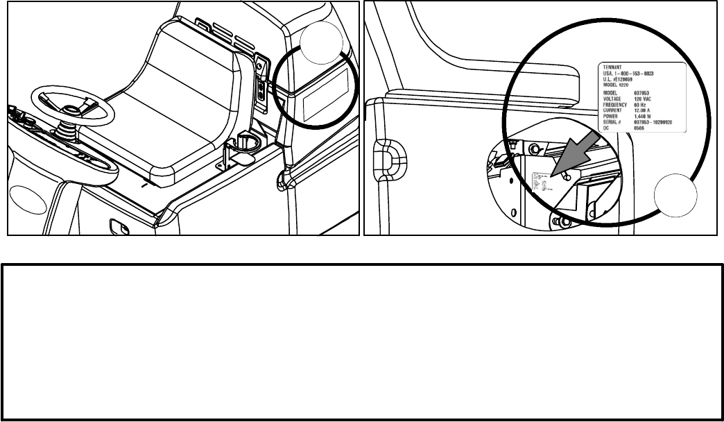
FOR REPLACEMENT PARTS
Identify machine model and serial number.
1. (A) Identify the machine model.
2. (B) Identify the machine serial number from the data label.
Refer to the Tennant Parts Manual
NOTE: Only use TENNANT Company supplied or equivalent parts. Parts and supplies may be ordered online,
by phone, by fax or by mail.
Tennant Company
PO Box 1452
Minneapolis, MN 55440
Phone: (800) 553--8033 or (763) 513--2850
www.tennantco.com
Specifications and parts are subject to change without notice.
Copyright E2006 TENNANT Company, Printed in U.S.A.
ii
R14 1032129 REV.01 (12-06)
page
SAFETY WARNINGS…………………………………………………..…………………………………
…
iv
MACHINE INFORMATION
Component Locator Charts
Control Panel Details…………………………………………………..…………………
…
1
Batter
y
Compartment Area Details…………………………………………………..…
…
2
Rear Machine Area Details…………………………………………………..…………
…
3
Underside Details…………………………………………………..……………………
…
4
Machine Specifications…………………………………………………..………………………
…
5
Machine Dimensions…………………………………………………..…………………………
…
6
MAINTENANCE
Circuit Breakers / Fuses…………………………………………………………………………
…
7
Char
g
in
g
Batteries………………………………………………………………………………… 7
Batter
y
Char
g
er Specifications…………………………………………………………
…
7
Machine Maintenance……………………………………………………………………………
…
8
A
fter Ever
y
Use……………………………………………………………………………
…
8
A
fter Ever
y
10 Hours of Use……………………………………………………………
…
9
A
fter Ever
y
80 Hours of Use……………………………………………………………
…
11
Motor Maintenance………………………………………………………………………
…
12
Batter
y
Maintenance……………………………………………………………………… 12
Primin
g
Solution S
y
stem…………………………………………………………………
…
13
Machine Jackin
g
…………………………………………………………………………………
…
13
Pushin
g
or Towin
g
Machine……………………………………………………………………… 13
Transportin
g
the Machine………………………………………………………………………… 14
Storin
g
the Machine………………………………………………………………………………
…
14
Recommended Maintenance Items……………………………………………………………
…
14
Troubleshootin
g
……………………………………………………………………………………
…
15
Fault Indicator Li
g
ht / Beep Codes………………………………………………………………
…
17
ELECTRICAL
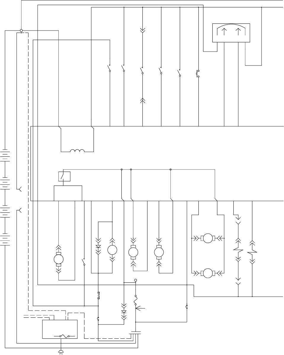
Electrical Schematic………………………………………………………………………………
…
18
Wire Harness Group………………………………………………………………………………
…
20
Seat Harness………………………………………………………………………………………
…
25
Read
y
Space & Extraction Plumbin
g
Dia
g
ram…………………………………………………
…
26
35 Pin Connector Detail…………………………………………………………………………
…
27
Electrical S
y
mbols & Terms……………………………………………………………………… 28
Ke
y
OFF Power Distribution - Batter
y
Char
g
er not connected………………………………
…
29
Ke
y
OFF Power Distribution - Batter
y
Char
g
er connected…………………………………… 30
Ke
y
ON, Operator on Seat………………………………………………………………………
…
31
Tank Level Switches………………………………………………………………………………
…
32
Horn & Hour Meter………………………………………………………………………………… 33
Propel Forward S
y
stem…………………………………………………………………………
…
34
Propel Reverse S
y
stem…………………………………………………………………………
…
35
Brakin
g
S
y
stem……………………………………………………………………………………
…
36
Lower Scrub Head………………………………………………………………………………… 37
Lower Scrub Head & Vacuum Shoes…………………………………………………………… 38
Brush Motors………………………………………………………………………………………
…
39
Vacuum Fan Motors………………………………………………………………………………
…
40
Solution Pump & Solenoid Valves
(
Read
y
Space Mode
)
……………………………………… 41
Solution Pump & Solenoid Valves
(
Extraction Mode
)
…………………………………………
…
42
Operational Modes & Interlocks…………………………………………………………………
…
43
Dia
g
nostic & Fault Alarms………………………………………………………………………
…
44
Dia
g
nostic & Confi
g
uration Modes………………………………………………………………
…
45
LED Locations & Descriptions…………………………………………………………………… 46
Displa
y
Software Revision Mode………………………………………………………………… 47
Self Test Mode……………………………………………………………………………………
…
48
Input Displa
y
Mode………………………………………………………………………………
…
49
Manual Mode………………………………………………………………………………………
…
50
Propel/Brake Dia
g
nostics………………………………………………………………………… 51
Reverse Alarm Select Mode……………………………………………………………………
…
53
Inputs & Outputs Table…………………………………………………………………………… 54
R14 Service Information Manual
Table of Contents
R14 1032129 REV.01 (12-06)
iii

BEFORE CONDUCTING TESTS:
z Read and Follow ALL Safety Warnings and Precautions in Operator's
Manual
z Always use an ESD (Electrostatic Discharge) strap when working near
the Control Board
z Be cautious when working near Control Board – Battery voltage is
always present, even with Key OFF
z Always Disconnect Batteries when removing or replacing components
DURING TESTS:
z Call Technical Services if Diagnostic Time Exceeds One Hour with
Unknown Cause or Course of Action
! !
R14 Service Information Manual
iv
R14 1032129 REV.01 (12-06)

Vacuum hose
connection indicator
Solution tank
empty indicator
Recovery tank
full indicator
Battery charge
level indicator
Fault
indicator
ReadySpace
ON/OFF button
Propel speed
selection button
Brush pressure
button
Extraction
ON/OFF button
Solution ON/OFF button
(extraction cleaning only)
Wand tool
ON/OFF button
R14 – Component Locator
S2 Horn
button
SW6 Forward/
Reverse switch
S1 Emergency stop
button (E-stop)
SW5 Main power
ON/OFF key switch
Control Panel Details
(Page 1 of 4)
R14 1032129 REV.01 (12-06)
1
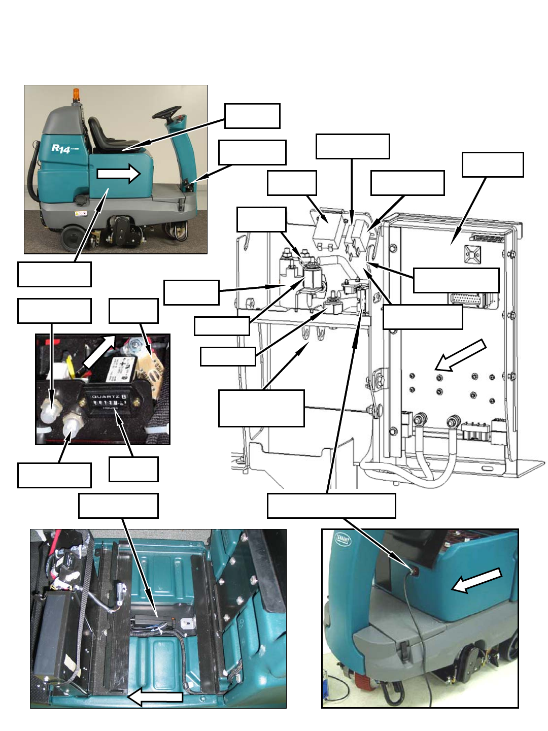
Batteries
(behind cover)
FRONT
FRONT
MTR5 Extractor
Shoes Actuator
Shown with seat, cover, and batteries removed
R14 – Component Locator
(Page 2 of 4)
Charger Plug &
SW1 Charger Interlock Switch
Battery Compartment Area Details
FRONT
FRONT
SW2 Seat
Switch
D1 & D2 Diodes
(below breakers)
Standoff 1
MTR6 Scrub Head
Actuator (upper
attachment point)
M1 Main
Contactor
U2 Throttle/
Brake Sensor
CB1 5A Circuit
Breaker
CB2 15A
Circuit Breaker
Standoff 2
FRONT
F1 100A
Fuse
H1 Hour
Meter
U1 Control
Board
F4 7.5A Fuse
(beside breakers)
F1 100A
Fuse
CB1 5A Circuit
Breaker
CB2 15A
Circuit Breaker
H1 Hour
Meter
2
R14 1032129 REV.01 (12-06)
FRONT
FRONT
SW4 Solution Tank
Empty Switch
SW3 Recovery Tank
Full Switch
MTR4 & MTR9
Vacuum Fan Motors
FRONT
FRONT
SW8 Hose
Switch
R14 – Component Locator
(Page 3 of 4)
Rear Machine Area Details
REAR VIEW
FRONT
R14 1032129 REV.01 (12-06)
3
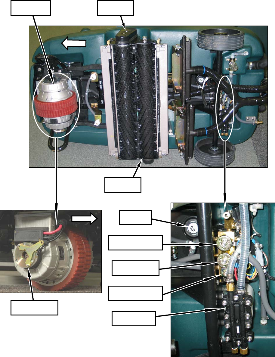
FRONT
MTR2 Front
Brush Motor
MTR3 Rear
Brush Motor
MTR1B Parking
Brake Solenoid
MTR1A
Propel Motor
LS1 Horn/
Alarm
SOL2 Extraction
Solenoid
SOL3 ReadySpace
Flush Solenoid
SOL1 ReadySpace
Solenoid
MTR7 Solution
Pump
R14 – Component Locator
(Page 4 of 4)
Underside Details
FRONT
4
R14 1032129 REV.01 (12-06)

MACHINE SPECIFICATIONS
MODEL R--14
Length 61.5 in / 1,560 mm
Width 32 / 813 mm
Height 52 / 1,325 mm
Minimum Aisle Turn 64 in / 1,630 mm
Weight -- less batteries 835 lb / 380 kg
Weight -- with batteries 1,225 lb / 560 kg
Solution tank capacity 32 gal / 121 L
Recovery tank capacity 28 gal / 106 L
Cleaning path width 27.5 in / 700 mm
Productivity rate (max) ReadySpace cleaning--theoretical: 13,000 ft2/hr / 1,208 m2/hr
ReadySpace cleaning--estimated actual: 10,000 ft2/hr / 929 m2/hr
Restorative extraction cleaning--theoretical: 7,500 ft2/hr / 697 m2/hr
Restorative extraction cleaning--estimated actual: 5,000 ft2/hr / 465 m2/hr
Travel speed Transport forward: 290 ft/min / 88 m/min
Transport reverse: 175 ft/min / 53 m/min
ReadySpace cleaning -- standard: 100 ft/min / 30 m/min
ReadySpace cleaning -- maximum: 150 ft/min / 46 m/min
Restorative extraction cleaning -- standard: 50 ft/min / 15 m/min
Restorative extraction cleaning -- maximum: 75 ft/min / 23 m/min
Maximum rated climb Transporting (empty tanks): 11°angle / 19.25% grade
Cleaning: 6°angle / 10.5% grade
Propel motor Transaxle,24V,62A,1.57hp/1153kW
Brush motor Two24V,20A,.54hp/0.40kW
Brush/roller speed 270 rpm
Solution pump 24 V, 5 A, 1.3 gpm / 4.9 L/min, 250 psi / 17.25 bar
Solution pressure/spray rate ReadySpace Cleaning: 30 psi / 2 bar at spray tips, 0.33 gal/min / 1.25 L/min
Restorative extraction cleaning: 52 psi / 3.6 bar at spray tips, 1.24 gal/min / 4.69 L/min
Vacuum motor Two24V,23A,.86hp/0.64kW
Water lift--air flow ReadySpace cleaning: 23.4 in / 594.4 mm -- 55 cfm / 26 L/sec
Restorative extraction cleaning: 59.4 in / 1,509 mm -- 6.5 cfm 3.1 L/sec
Voltage DC 24 VDC
Total power consumption ReadySpace cleaning: 60 A nominal
Restorative extraction cleaning: 65 A nominal
Battery capacity Four 6 V, 335 Ah/20 hr rate
Maximum run time 2.5 hours*
Battery charger 120 VAC, 60 Hz, 24 VDC, 30 A output
Decibel rating at operator ear, indoors 73 dBA**
* Run times are based on Continuous Scrubbing Run Times.
** Sound pressure (ISO 11201) as recommended by the American Association of Cleaning Equipment Manufacturers (AACEM) and OSHA.
Specifications are subject to change without notice.
R14 Specifications
R14 1032129 REV.01 (12-06)
5
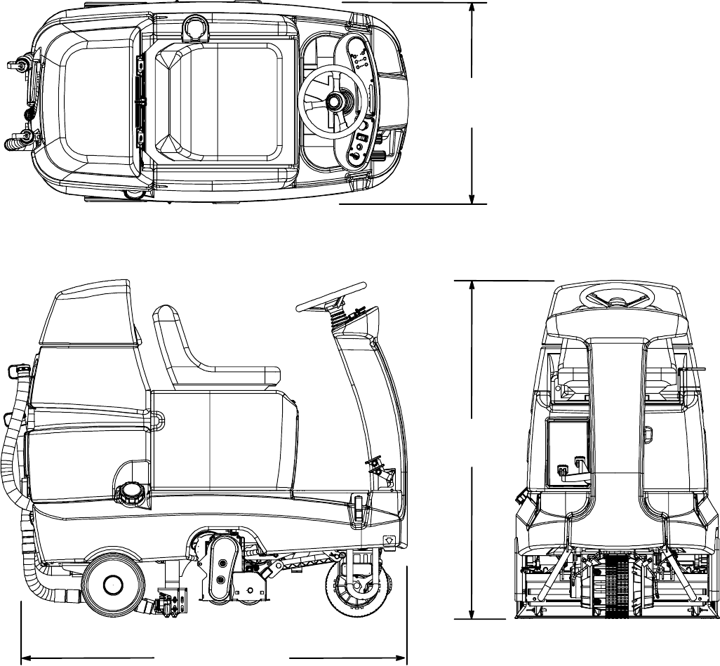
MACHINE DIMENSIONS
32 in
813 mm
61.5 in / 1,560 mm
52 in
1,325 mm
R14 Dimensions
6
R14 1032129 REV.01 (12-06)
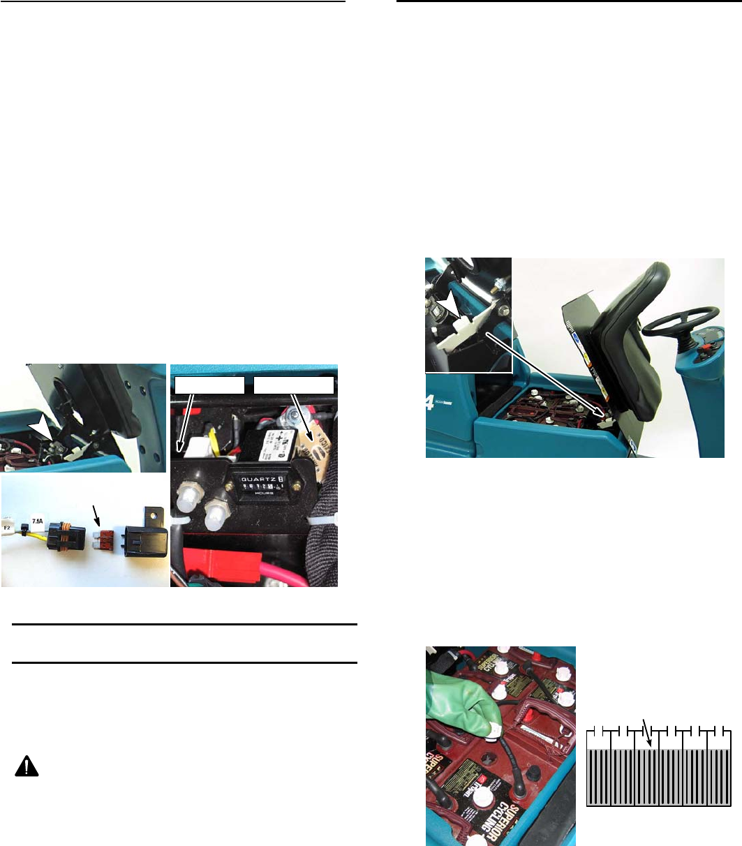
CIRCUIT BREAKERS / FUSES
The machine is equipped with two resettable circuit
breakers and two fuses to protect the machine from
damage. If a breaker should trip, determine the cause,
allow the motor to cool then reset the circuit breaker
button.
The circuit breakers and the fuses are located inside
the battery compartment near the hour meter (Figure
30). When replacing a blown fuse never substitute a
higher amp rated fuse than specified.
CIRCUIT BREAKERS:
5 A -- controller key switch input
15 A -- solution pump/solution solenoid/ brake/horn/
hour meter (See page 30 for solution solenoid
reference)
FUSES:
100 A -- main (part no. 86379)
7.5 A -- solution pump (part no. 1016039)
100 A Fuse
5A
15A
7.5 A Fuse
7.5 A Fuse
FIG. 30
CHARGING BATTERIES
ATTENTION: To prolong the life of the batteries
only recharge the batteries if the machine was
used for a total of 30 minutes or more. Do not leave
batteries discharged for lengthy periods.
WARNING: Fire Or Explosion Hazard.
Batteries Emit Hydrogen Gas. Keep Sparks And
Open Flame Away. Keep Battery Compartment
Open When Charging.
FOR SAFETY: When servicing batteries, wear
protective gloves and eye protection when
handling batteries and battery cables. Avoid
contact with battery acid.
BATTERY CHARGER SPECIFICATIONS
SCHARGER TYPE:
-- FOR WET (Lead acid) BATTERIES
SOUTPUT VOLTAGE - 24 VOLTS
SOUTPUT CURRENT - 30 AMPS
SAUTOMATIC SHUTOFF CIRCUIT
SFOR DEEP CYCLE BATTERY CHARGING
1. Park the machine on a flat, dry surface and turn the
key off. Make sure the area is well ventilated.
2. Tilt the seat forward for ventilation (Figure 39). Use
the seat stand to hold the seat up.
FIG. 39
3. Check the battery fluid level before charging (Figure
40). The fluid level should slightly cover the battery
plates. Add distilled water if low. DO NOT
OVERFILL. The fluid will expand and may overflow
when charging.
FOR SAFETY: When servicing batteries, wear
protective gloves and eye protection when
handling batteries and battery cables. Avoid
contact with battery acid.
Battery Plates
FIG. 40
4. Connect the charger’s AC power supply cord into a
properly grounded wall outlet.
(Page 1 of 11)
R14 1032129 REV.01 (12-06)
7
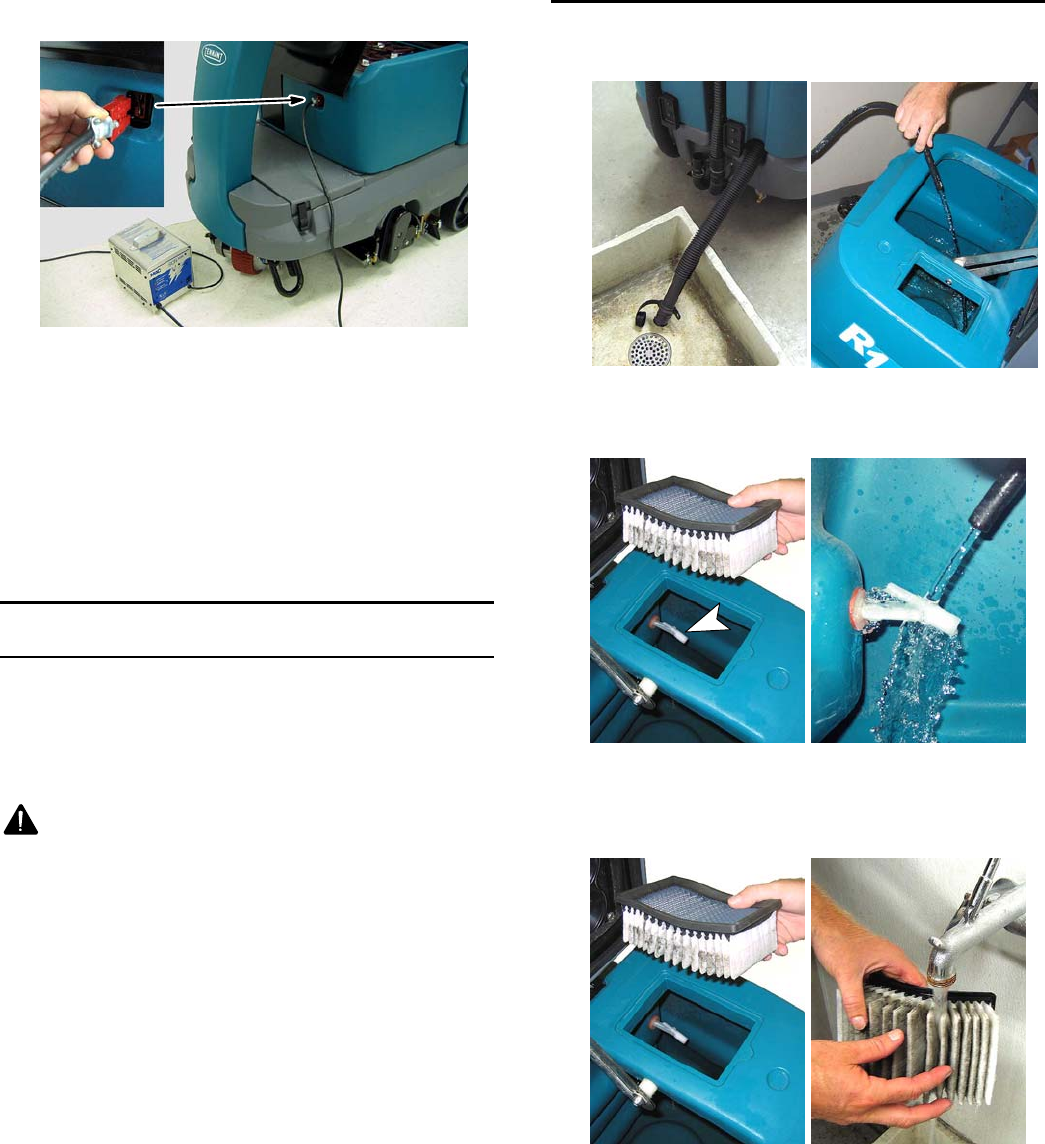
5. Connect the charger’s DC cord into the machine’s
battery charge receptacle (Figure 41).
FIG. 41
6. The supplied charger will automatically begin
charging and shut off when fully charged.
NOTE: The machine will not operate when charging.
ATTENTION: Do not disconnect the charger’s DC
cord from the machine’s receptacle when the
charger is operating. Arcing may result. If the
charger must be interrupted during charging,
disconnect the AC power supply cord first.
MACHINE MAINTENANCE
To keep the machine in good working condition,
perform the following maintenance procedures.
FOR SAFETY: Before leaving or servicing machine,
stop on a level surface and turn off machine.
WARNING: Electrical Hazard. Disconnect
Battery Cables Before Servicing Machine.
ATTENTION: Contact an authorized service center
for machine repairs. Machine repairs performed by
other than an authorized person will void your
warranty.
AFTER EVERY USE
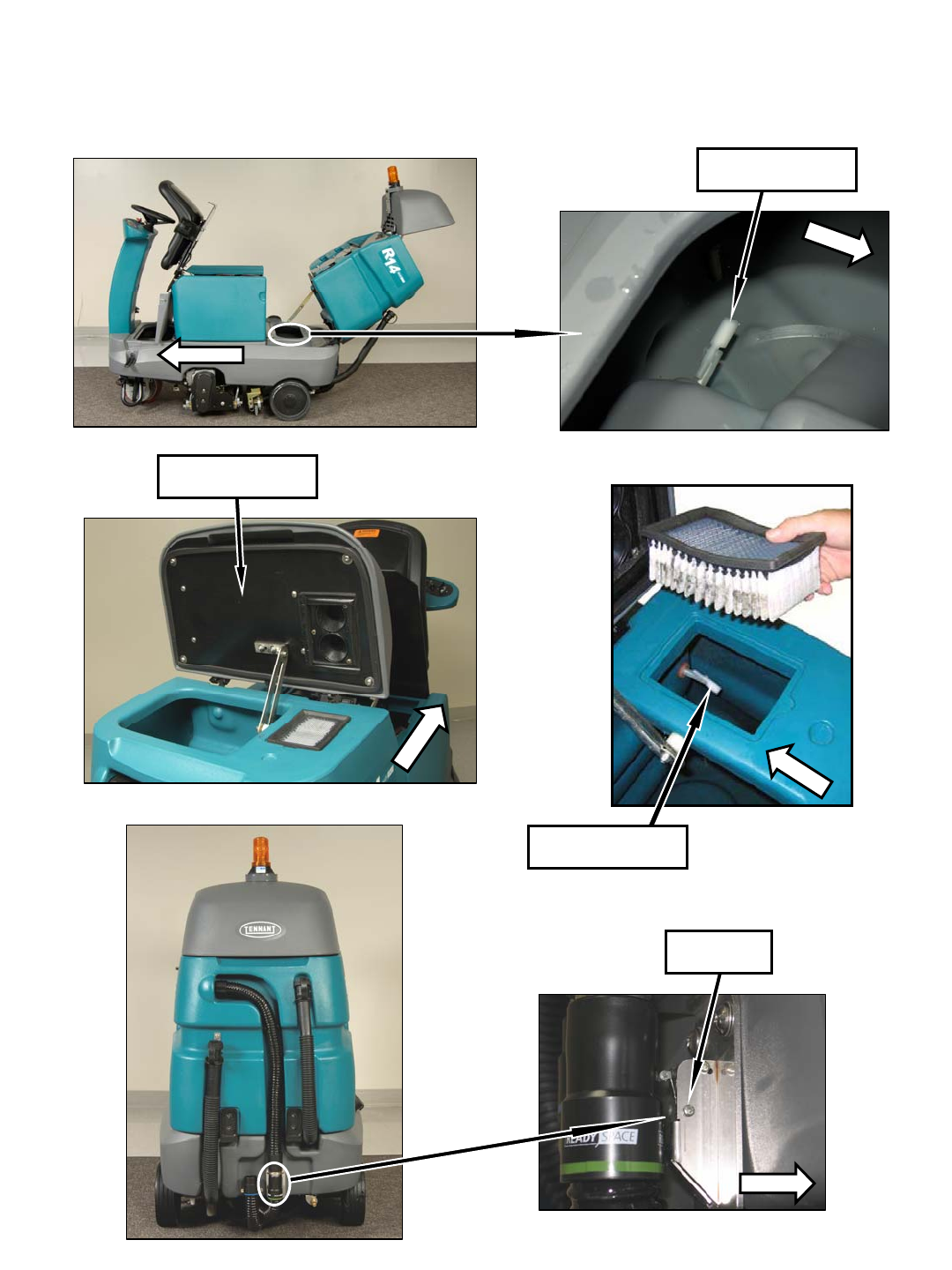
1. Drain and rinse out the recovery tank (Figure 42).
FIG. 42
2. Rinse off the recovery tank float sensor
(Figure 43).
FIG. 43
3. Clean the vacuum fan filter with low water pressure
(Figure 44). Allow the filter to completely dry before
reinstalling.
FIG. 44
8
R14 1032129 REV.01 (12-06)
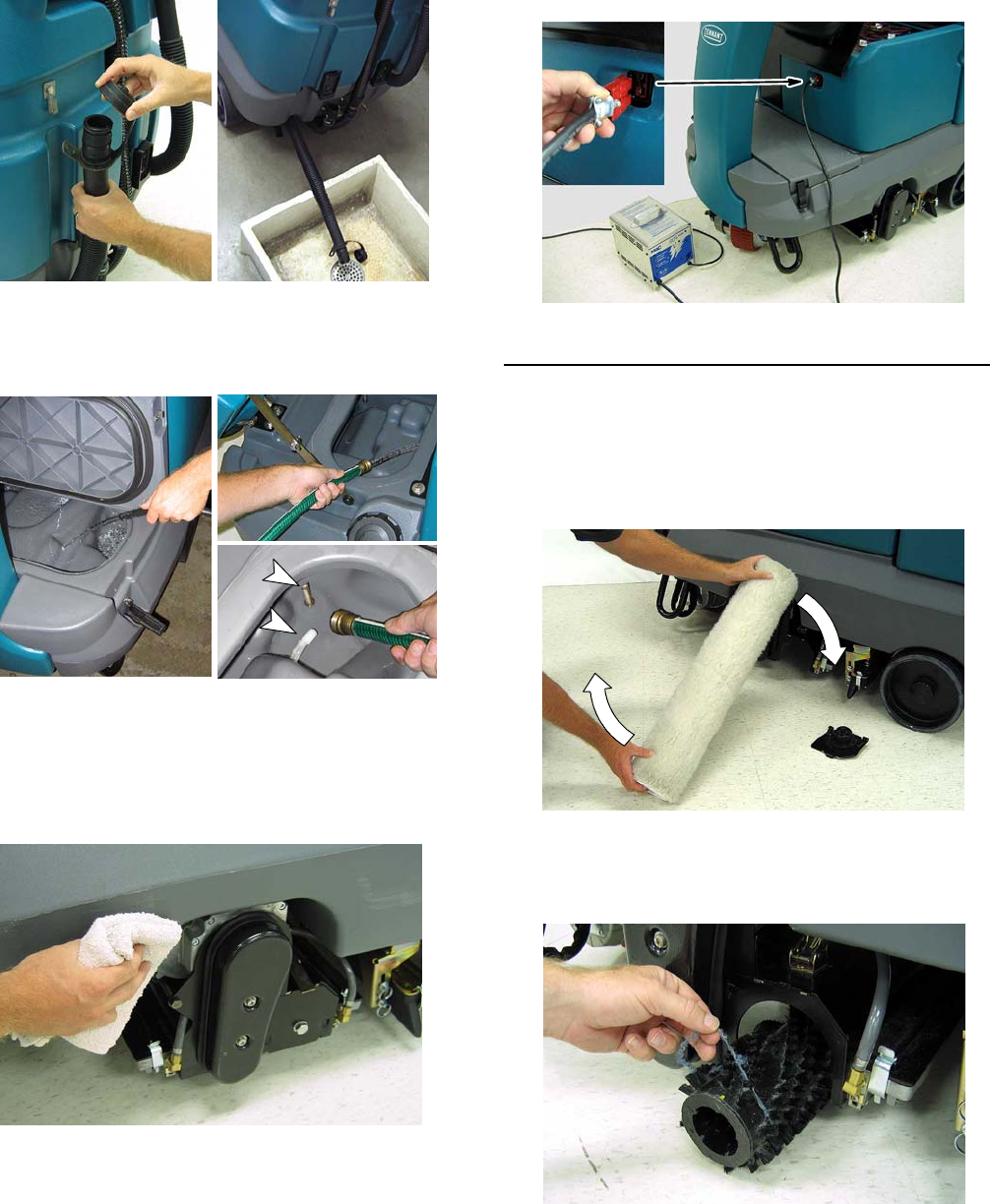
4. Drain the solution tank (Figure 45).
FIG. 45
5. Clean the front and back half of the solution tank.
Clean the solution tank sensor and filter
(Figure 46).
FIG. 46
6. Clean the outside surface of the machine with an
all purpose cleaner and damp cloth (Figure 47).
FOR SAFETY: When cleaning machine, do not
power spray or hose off machine. Electrical
malfunction may occur.
FIG. 47
7. Recharge the batteries if the machine was used for
at total of 30 minutes or more (Figure 48).
FIG. 48
AFTER EVERY 10 HOURS OF USE
1. Flip the ReadySpace rollers end-for-end every 10
hours (Figure 49). Replace the rollers if an air gap
is visible between the two rollers. The roller life is
rated at 100 hours of use under normal cleaning
conditions. Always replace rollers as a set.
FIG. 49
2. Remove any entangled carpet fibers and debris
from the extractor brushes (Figure 50). Replace the
brushes if damaged or worn.
FIG. 50
R14 1032129 REV.01 (12-06)
9
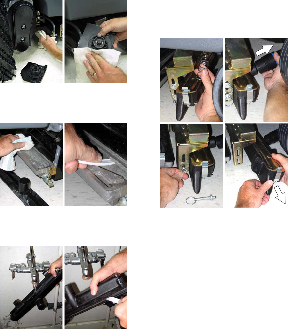
3. Clean the underside of the scrub head and the idler
plate (Figure 51).
FIG. 51
4. Remove the covers from the ReadySpace vacuum
shoes and wipe out the debris build up (Figure 52).
Remove the ReadySpace rollers and use a pointed
object to clean vacuum shoe intake slot.
FIG. 52
5. Remove the extraction vacuum shoes and rinse out
the debris buildup (Figure 53). Use a pointed object
to clean the vacuum shoe intake slot. (See Figure
54 for Extraction Vacuum Shoe Removal.)
FIG. 53
Extraction Vacuum Shoe Removal (Figure 54):
a. With the scrub head in the up position, remove
the two down pressure springs. Lower the
scrub head after removing springs.
b. Disconnect the vacuum hose.
c. Pull the two mounting pins
d. Remove shoe from scrub head.
a. b.
c. d.
FIG. 54
10
R14 1032129 REV.01 (12-06)
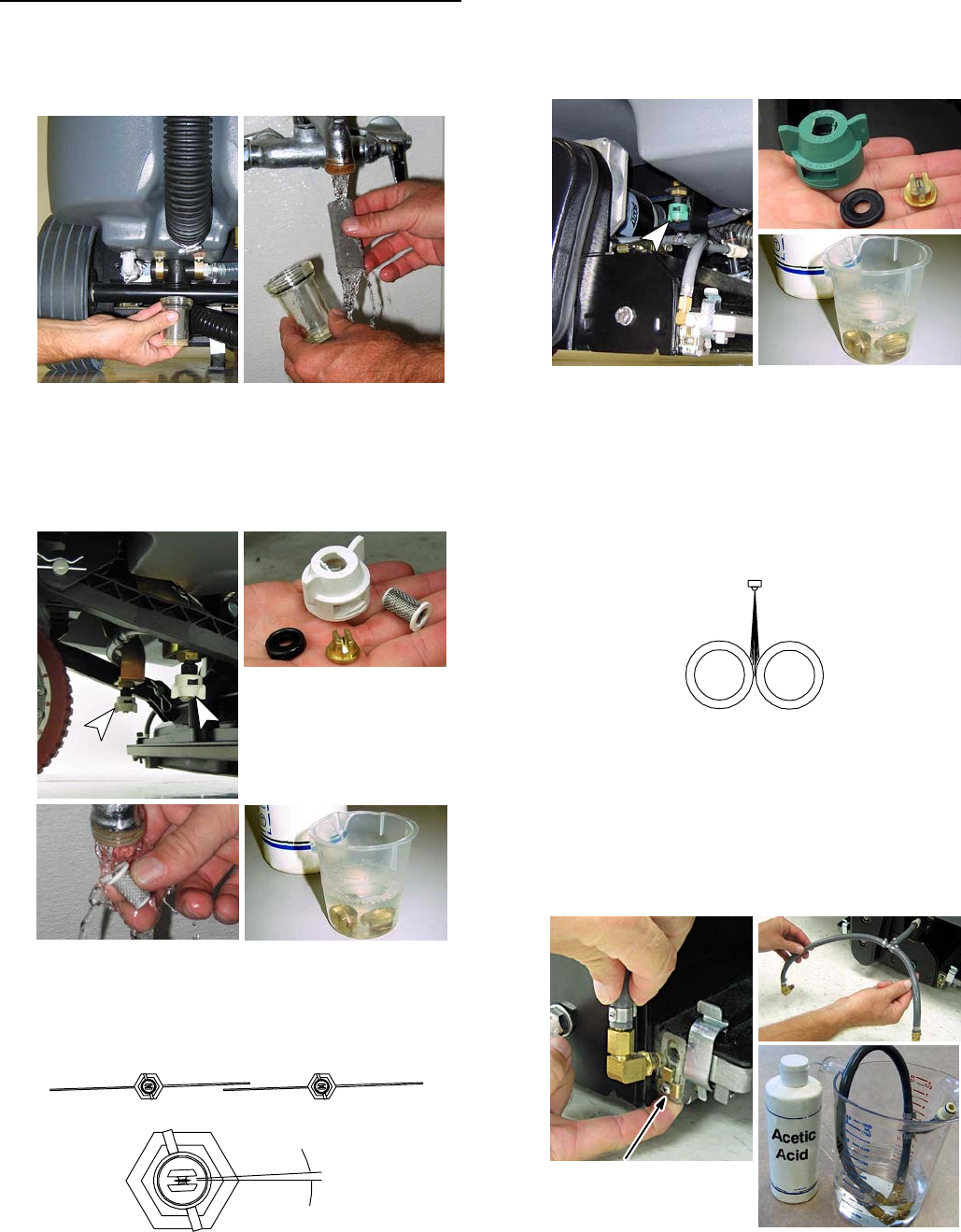
AFTER EVERY 80 HOURS OF USE
1. Empty the solution tank and remove the solution
tank filter from under the machine and rinse out the
screen (Figure 55).
FIG. 55
2. Remove the two Restorative Extraction spray
nozzles and soak the tips and screens in an acetic
acid solution (Figure 56). Use a plastic bristle brush
to clean clogged spray tips. Do not use a pointed
object to clean tips, damage will occur.
Restorative Extraction
Spray Nozzle
WHITE CAP
TIP #11005E
p/n 1022378
acetic acid
solution
FIG. 56
When replacing the extraction spray nozzles, turn
the cap until it clicks into position. The position of
the spray nozzles is set at a 3°angle (Figure 57).
TOP VIEW
Restorative extraction spray pattern
3°
Spray nozzle angle
FIG. 57
3. Remove the two ReadySpace spray nozzles and
soak the tips in an acetic acid solution (Figure 58).
Use a plastic bristle brush to clean clogged spray
tips. Do not use pointed objects to clean tips,
damage will occur.
ReadySpace Spray Nozzle
GREEN CAP / TIP #11002 p/n 575283000
acetic acid
solution
FIG. 58
When replacing the ReadySpace spray nozzles,
turn the cap until it clicks into position. The position
of the spray nozzles is set to spray directly
between the two rollers (Figure 59).
ReadySpace Spray Pattern
ReadySpace Rollers
FIG. 59
4. Remove the two ReadySpace vacuum shoe flush
lines and soak them in an acetic acid solution
(Figure 60). Do not remove the tips from the flush
lines.
NOTE: During ReadySpace operation the flush line
spray tips will spray every 21/2minutes for 3 seconds.
Push retainer tab upward
to release spray tip.
FIG. 60
R14 1032129 REV.01 (12-06)
11
5. Flush the plumbing system with an acetic acid
solution to dissolve normal alkaline buildup. This
procedure requires the machine to sit overnight.
a. Remove rollers/brushes from the scrub head.
b. Pour 3 gal / 11 L of hot water into the solution
tank. Do not exceed 140°F/60°C.
c. Add the acetic acid solution according to the
mixing directions on the bottle.
FOR SAFETY: When using chemicals follow mixing
and handling instructions on chemical containers.
d. Place the machine in an area with a floor drain.
e. Operate both cleaning technologies for one
minute each.
f. Turn the key off and let the machine sit
overnight to allow the acetic acid solution to
breakdown the alkaline buildup.
g. Next day, disperse the remaining acetic acid
solution and rinse the solution system with 11
liters (3 gal) of clean water.
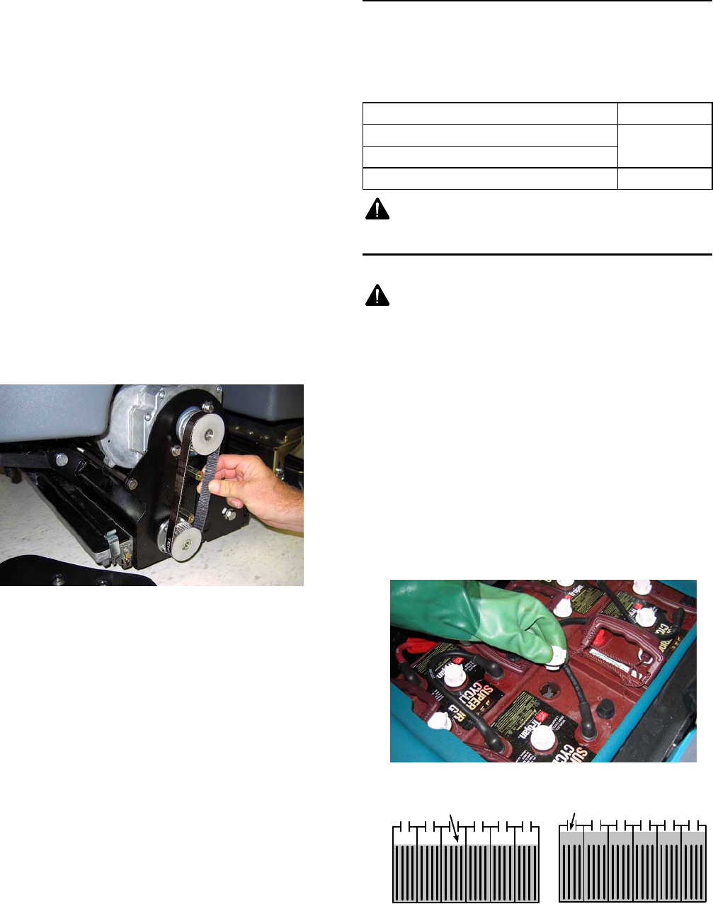
6. Check the belt tension on the two brush motors.
Tighten the belt if able to twist it more than 90°at
midpoint (Figure 61).
FIG. 61
FOR SAFETY: When servicing machine,
disconnect the battery connections.
7. Clean the batteries and check the fluid levels (See
BATTERY MAINTENANCE).
8. Check for loose or worn battery cables. Replace if
worn.
9. Lubricate all pivot points with a water resistant
grease.
10. Check the machine for water leaks.
11. Check the machine for loose nuts and bolts.
MOTOR MAINTENANCE
Contact an Authorized Tennant Service Center for
carbon brush replacement.
Replace the carbon brushes as directed.
Carbon Brush Replacement Hours
Propel Motor 750
Vacuum Motors
Brush Motors 1000
WARNING: Electrical Hazard. Disconnect
Battery Cables Before Servicing Machine.
BATTERY MAINTENANCE
WARNING: Fire Or Explosion Hazard.
Batteries Emit Hydrogen Gas. Keep Sparks And
Open Flame Away. Keep Battery Compartment
Open When Charging.
FOR SAFETY: When servicing batteries, wear
protective gloves and eye protection. Avoid
contact with battery acid.
To prolong the life of the batteries only recharge the
batteries if the machine is used for a total of 30 minutes
or more. Never leave batteries discharged for lengthy
periods.
1. Check battery fluid levels before and after
charging. The fluid should be at the level shown
(Figure 62). Add distilled water if low. DO NOT
OVERFILL. The fluid will expand and may overflow
when charging.
Before Charging After Charging
CORRECT BATTERY FLUID LEVEL:
Fluid level slightly
above battery plates
Fluid level slightly
below sight tubes
FIG. 62
12
R14 1032129 REV.01 (12-06)
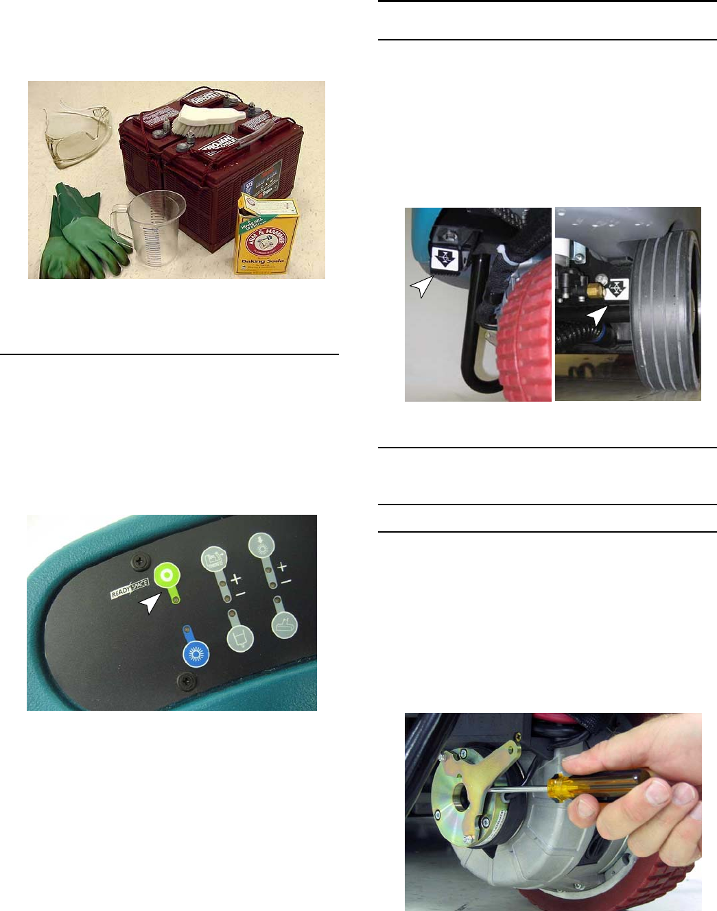
2. Clean the batteries and terminals to prevent battery
corrosion. Use a scrub brush with a mixture of
baking soda and water (Figure 63).
ATTENTION: Do not allow the baking soda solution
to enter the batteries.
FIG. 63
3. Check for loose or worn battery cables. Replace if
worn.
PRIMING SOLUTION SYSTEM
To prime the machine’s solution system, operate the
ReadySpace technology for approximately one minute
(Figure 64). Once primed, the machine can be used for
restorative extraction cleaning.
If the solution system is completely dry or if you notice
center streaking when restorative extraction cleaning,
the solution system must be primed.
FIG. 64
MACHINE JACKING
Use the designated jacking locations for jacking up the
machine (Figure 65). Empty the recovery and solution
tanks before jacking. Use a jack capable of supporting
the weight of the machine. Position the machine on a
flat, level surface and block the tires before jacking.
FOR SAFETY: When servicing machine, jack
machine up at designated locations only. Use jack
or hoist that will support machine weight. Block
machine up with jack stands.
FIG. 65
PUSHING, TOWING, AND TRANSPORTING
MACHINE
PUSHING OR TOWING THE MACHINE
Before attempting to push or tow the machine, the
brake must be disengaged. To disengage the brake,
insert a small standard screwdriver between the
electronic brake lever and the hub (Figure 66).
FOR SAFETY: When brake is disengaged, do not
push or tow the machine on inclines.
FOR SAFETY: When brake is disengaged, do not
operate machine.
FIG. 66
R14 1032129 REV.01 (12-06)
13
Only push or tow the machine on a level surface. Do
not exceed 2 mph / 3.2 kph. When towing machine,
only tow it from the front by the stabilizer arms
(U--shape bars).
Immediately after pushing or towing the machine,
enable the brake. Never operate the machine with the
brake disabled.
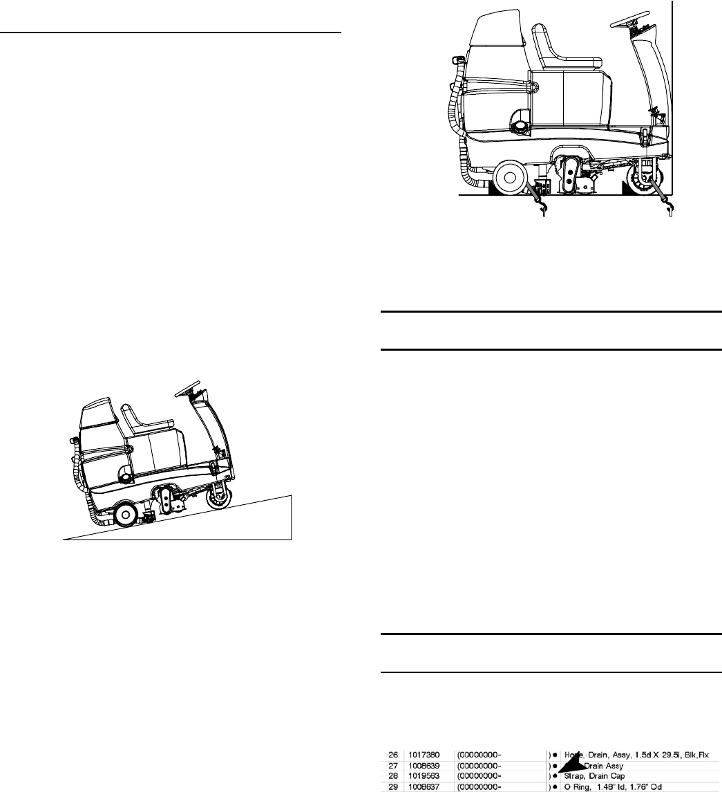
TRANSPORTING THE MACHINE
When transporting the machine by use of trailer or
truck, carefully follow the loading and tie--down
procedures:
FOR SAFETY: When transporting machine, go
slowly on inclines and slippery surfaces.
1. Empty the solution tank and recovery tank.
2. Raise the scrub head to the up position.
3. Load the machine using a ramp that can support
the machine weight and operator. Do not operate
the machine on a ramp incline that exceeds an 11°
angle (Figure 67). A winch must be used when
ramp incline exceeds an 11°angle.
FOR SAFETY: When transporting machine, use a
ramp that can support the machine weight and
operator. Do not operate the machine on a ramp
incline that exceeds an 11°angle. Use tie--down
straps to secure machine to truck or trailer.
11°maximum ramp angle
FIG. 67
4. Once loaded, position the front of the machine up
against the front of the trailer or truck. Lower the
scrub head and turn the key off (Figure 68).
5. Place a block behind each wheel (Figure 68).
6. Secure the front and rear of the machine with
tie--down straps (Figure 68). Route the front strap
through the stabilizer arms (U--shape bars). Route
the rear strap above the rear axle at center. It may
be necessary to install tie-down brackets to the
floor of your trailer or truck.
FIG. 68
NOTE: When transporting machine in freezing
temperatures see STORING MACHINE, step 5.
STORING MACHINE
1. Charge the batteries before storing. Never store
machine with discharged batteries.
2. Drain and rinse the tanks thoroughly.
3. Park the machine in a dry area with the scrub head
in the raised position.
4. Open the recovery tank cover to promote air
circulation.
5. If storing machine in freezing temperatures be
certain to drain tanks, purge pump and remove the
solution tank filter located under the machine at
rear.
ATTENTION: Do not expose machine to rain, store
indoors.
RECOMMENDED STOCK ITEMS
Refer to the Parts List Manual for recommended stock
items. Stock Items are clearly identified with a bullet
preceding the parts description. See example below:
14
R14 1032129 REV.01 (12-06)

TROUBLESHOOTING
PROBLEM CAUSE SOLUTION
No power Key turned off Turn key on
Batteries discharged Recharge batteries
Loose or disconnected battery cable Secure battery cable connections
Circuit breaker tripped Reset 5 A circuit breaker
Main fuse blown Replace 100 A main fuse
Fault indicator light is on or
machine is beeping
Machine fault has been detected See FAULT INDICTOR LIGHT/BEEP
CODES
Machine does not propel Operator not seated Operator must be seated to operate
machine
Seat sensor wire harness plug is dis-
connected
Connect seat sensor wire harness
plug
Faulty control board Contact Service Center
Faulty drive motor or wiring Contact Service Center
Worn carbon brushes in motor Contact Service Center
Brush motor(s) do not operate Low voltage interrupt activated Recharge batteries
Loose or broken belt Contact Service Center
Faulty brush motor or wiring Contact Service Center
Worn carbon brushes in motor Contact Service Center
Vacuum motor(s) do not operate Low voltage interrupt activated Recharge batteries
Faulty vacuum motor or wiring Contact Service Center
Worn carbon brushes in motor Contact Service Center
Scrub head will not lower. Cleaning button not pressed Press cleaning button
Low voltage interrupter activated Recharge batteries
Full recovery tank Empty recovery tank
No solution spray or solution spray
is uneven (streaking occurs)
Solution system needs priming Prime solution system (See PRIMING
SOLUTION SYSTEM)
Scrub head not lowered Press cleaning button to lower head
Solution switch is turned off
(Extraction Cleaning)
Turn solution switch on
Solution tank is empty Refill solution tank
Clogged spray tips Clean spray tips
Plugged solution tank filter Clean solution tank filter
Clogged solution line filter Clean solution line filter
Faulty pump or solution solenoid Contact Service Center
Clogged solution line Flush plumbing system
Spray nozzle out of alignment Realign spray nozzle
R14 1032129 REV.01 (12-06)
15

TROUBLESHOOTING -- Continued
PROBLEM CAUSE SOLUTION
Poor water pickup. Worn ReadySpace rollers Replace rollers
Clogged vacuum shoes Clean vacuum shoes
Vacuum shoe springs missing
(Extraction cleaning)
Replace vacuum shoe springs
Loose recovery tank drain hose cap Tighten cap
Loose or disconnected vacuum hose Connect hose cuffs securely
Clogged vacuum hose Remove clogged debris
Defective vacuum hose Replace vacuum hose
Recovery tank cover not down Close cover
Worn tank cover gasket Replace gasket
Excessive foam/cream appears
on the floor during ReadySpace
cleaning
Cleaning detergents were added to
solution tank
Drain and rinse out solution tank and
refill with water only. Do not add
cleaning detergents
Unapproved pre--treatment detergent
used
Use approved pre--treatment
detergent
Short run time Low battery charge Charge batteries
Batteries need maintenance See BATTERY MAINTENANCE.
Faulty charger Repair or replace battery charger
Spray nozzles drip when not in
use
(See SOLUTION FLOW
DIAGRAM for reference)
Clogged spray tip filter/check valve
(Restorative Extraction spray tips)
Clean or replace spray tip filter
Clogged or faulty solution solenoid. Clean or replace solution solenoid
16
R14 1032129 REV.01 (12-06)
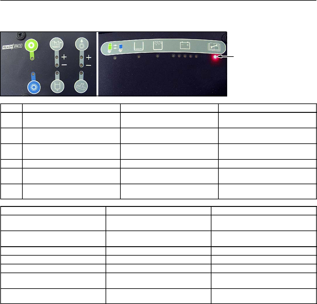
FAULT INDICATOR LIGHT/BEEP CODES
The fault indicator light will come on or the horn will beep if the machine detects a fault.
Use the following fault codes to determine cause of fault.
1
2
3
4
5
6
Fault indicator light
REF. FAULT LIGHT CODE FAULT SOLUTION
1Fault light blinks Propel motor overload
Exceeded maximum incline
Avoid steep inclines. Restart key
to reset. Contact Service Center.
1&2 Fault light and Speed (+) light
blink
Rear brush motor overload Inspect brush for obstruction.
Contact Service Center.
1&3 Fault light and Solution light blink Front brush motor overload Inspect brush for obstruction.
Contact Service Center.
1&4 Fault light and Extract light blink Vacuum motor overload Contact Service Center.
1&5 Fault light and Brush pressure (+)
light blink
Scrub head actuator overload Contact Service Center.
1&6 Fault light and Brush pressure (--)
light blink
Extractor shoe actuator overload Contact Service Center.
FAULT BEEP CODE FAULT SOLUTION
Horn repeatedly beeps two times Propel pedal depressed without
operator in seat
Operator must be seated to operate
machine
Horn repeatedly beeps four times Key switch turned on with propel
pedal depressed
Release propel pedal before turning
key on
Horn repeatedly beeps five times Throttle system failure Contact Service Center
Horn repeatedly beeps six times Brake system failure Contact Service Center
Horn repeatedly beeps seven times Parking brake system failure Contact Service Center
Horn repeatedly beeps eight times Emergency stop button activated Turn button clockwise and restart key
to reset
Horn repeatedly beeps nine times Key switch turned on with battery
charger plugged into machine
Unplug battery charger before
starting machine
R14 1032129 REV.01 (12-06)
17
1035160
MTR3
REAR BRUSH MOTOR
P1--A P1--B
MTR1A
P1--1 P1--2
SOL1
RS SOLENOID VALVE
P1--1 P2--1
6VDC
+----
CONN29
B
6VDC
+----
SW1
CHARGER INTERLOCK
P1--1 P2--1
A
6VDC
+----
S1
EMERGENCY
P1--1 P2--1
MTR4
VAC 1 MOTOR
P1--A
P1--B
CONN1
A
CONN8A
A
SW3
SW SPST --MOM
P1--1 P2--1
6VDC
+----
MTR1B
P1--B P1--A
S2
HORN SW PUSHBUTTON
P1--1 P2--1
SW2
SEAT SWITCH
P1--1 P2--1
CONN10B
B
U1
PROPEL1
J10--2
PROPEL2
J10--1
FLYBACK PATH
J6--13
+24VDC POWER
J11
MAIN CONT
J6--5
FRONT BRUSH +
J8--1
FRONT BRUSH --
J8--2
VAC A
J9--1
VAC B
J9--2
REAR BRUSH --
J8--3
REAR BRUSH +
J8--4
BRAKE OUTPUT
J6--27
WATER SOL
J6--4
PWR GND J7
SIGNAL RETURN J6--35
INTERLOCK J6--18
SOL LOW J6--8
REC FULL J6--20
THROTTLE SIG J6--34
HOSE SWITCH
SEAT J6--7
HORN SW J6--10
BRAKE INPUT J6--33
LOGIC PWR SUPPLY
J6--24
1AMPLOWD
J6--17
If J6--6 is input
remove Q6
and populate R88
If J6--33 or J6--34
is less than 0.5 Volts,
propel is disabled.
If unused apply 24 Volts
SW8
HOSE SWITCH
P1--1 P2--1
CB2
CRKT BRKR 15A
P2--1P1--1
SW4
SW SPST --MOM
P1--A P1--B
FUSE 100A
MTR9
VAC 2 MOTOR
P1--A
P1--B
CONN11B
B
STANDOFF2
U2
GILL SENSOR
FWD
P1--B
REV
P1--C
PWR
P1--A
GND
P1--D
FUSE
D1 P1--M
P1--F +--
CB1
CRKT BRKR 5A
P2--1P1--1
MTR2
FRONT BRUSH MOTOR
P1--AP1--B
M1A
P6--1
P5--1
M1B
P1--1
P2--1
P3--1 P4--1
P5--1
SW5
SW SPST KEYSWITCH
P1--1 P2--1
D2
P1--M
P1--F
+--
27F/GRN 32D/ORA
42F/BRN
4/YEL
42E/BRN
4B/YEL
1A/RED
1C/RED
1B/RED
30/TAN
3/ORA
28/GRY
42D/BRN
10/TAN
14C/YEL
32/BRN
27/PUR
25/RED
5A/GRN
42G/BRN
6A/BLU
6/BLU
14/YEL
8/GRY
5B/GRN
26/BLU
7/PUR
42C/BRN
5/GRN
14H/YEL
29/WHT
13A/BLK
16/BLU
31/PNK
42A/BRN
9/WHT
24/BLK
2/BRN
13D/BLK
12/BRN12A/BRN
13E/BLK
50/RED
14B/YEL
14A/YEL
BLU
BLK
15/GRN
47/PUR 42B/BRN
BLACK
50A/RED
1.2 AMPS
120 AMP
30 AMP
10 AMP
30 AMP
40 AMP
DIRECT
CONNECTION
FUSE TO
CONTACTOR
(+)STUDONBOARD
(--) STUD ON BOARD
+
ON--BOARD
CHARGER
OPTION
SW1 NOT USED FOR
ON BOARD CHARGER OPTION
TO SW1 CHARGER INTERLOCK
1/RED 13/BLK
13C/BLK
13B/BLK
STANDOFF1
CHARGER
PLUG NOT USED WITH
ON--BOARD CHARGER
PLUG
J6--11
ON--BOARD
RELAY
PROPEL MOTOR
CONTACTOR
PARKING BRAKE
F1
18
R14 1032129 REV.01 (12-06)
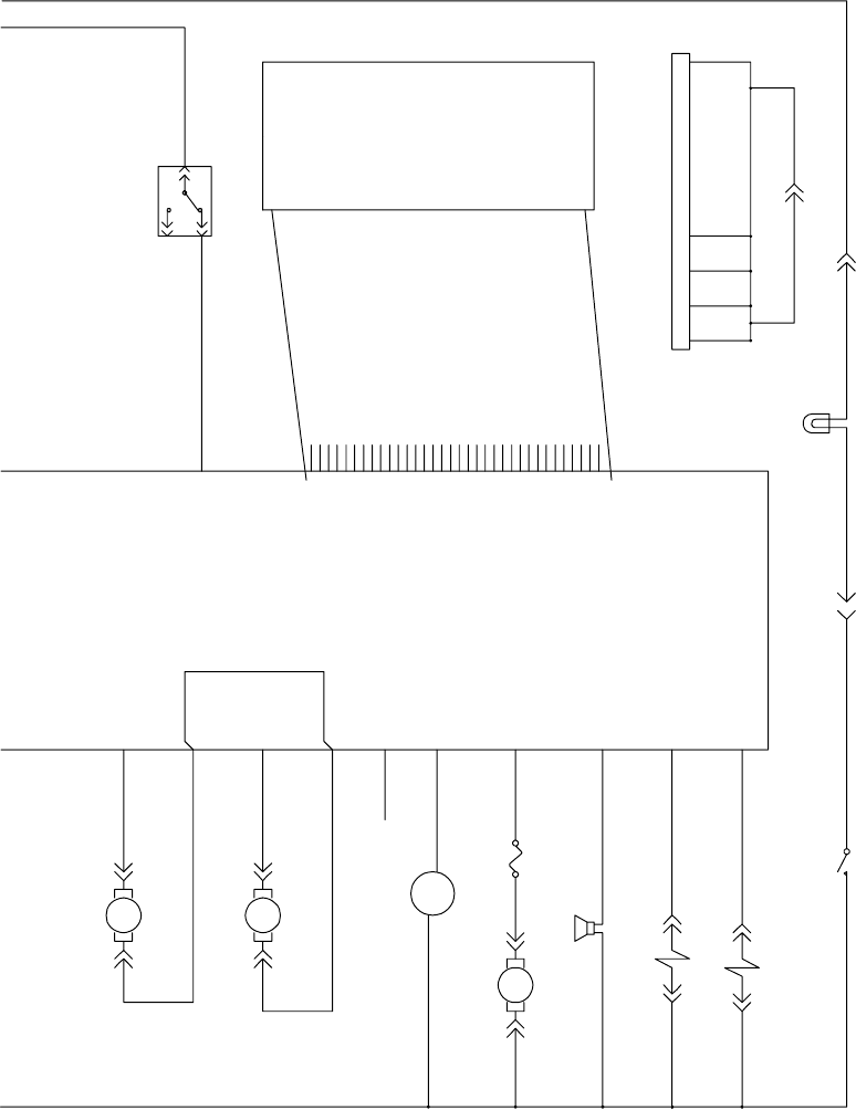
1035160
LEGEND
CB1 = CIRCUIT BREAKER 5A #383720
CB2 = CIRCUIT BREAKER 15A #383722
D1 = DIODE #222290
D2 = DIODE #222290
F1 = FUSE 100A #86379
F2 = FUSE 7.5A #1016039
H1 = HOUR METER #377433
LP1 = FLASHING LAMP #1015170
LS1 = HORN #1018505
M1A = CONTACTOR #02424
MTR1A = PROPEL MOTOR #1024247
MTR1B = PARKING BRAKE #372869
MTR2 = FRONT BRUSH MOTOR #1023355
MTR3 = REAR BRUSH MOTOR #1023355
MTR4 = VACUUM MOTOR 1 #1013432
MTR5 = EXTRACTOR MOTOR (PM) #1023355
MTR6 = ACTUATOR MOTOR (PM) #1010895
MTR7 = SOLUTION PUMP #1022343
MTR9 = VACUUM MOTOR 2 #1013432
S1 = EMERGENCY SWITCH #1011735
S2 = HORN SWITCH PUSH BTN #1014832
SOL1 = RS SOLENOID VALVE
#1023693 (3 STATION / #1025177 (2 STATION)
SOL2 = EXTR SOLENOID VALVE
#1023693 (3 STATION / #1025177 (2 STATION)
SOL3 = FLUSH SOLENOID VALVE
#1023693 (3 STATION / #1025177 (2 STATION)
SW1 = CHRGR INTRLCK SWITCH #600437
SW2 = SEAT SWITCH #223078
SW3 = SOL REC FULL FLOAT SWITCH #385685
SW4 = SOL LOW FLOAT SWITCH #602919
SW5 = KEY SWITCH #1016789
SW6 = DIRECTIONAL SWITCH #1013763
SW7 = LIGHT SWITCH #1023308
U1 = CONTROL BOARD #1024921
U2 = GILL SENSOR #1011562
= TOUCH PANEL #1024154
LS1
HORN
P1--1 P2--1
C
MTR5
ACTUATOR MOTOR
P1--AP1--B
SEAT SWITCH
C
H1
HOUR METER
+
P1--1
-- P2--1
MTR7
SOLUTION PUMP
P1--A P1--B
SW6
SW SPDT -- 768529
P2--1
P1--1
P3--1
ON
ON
OFF
EXTRACT A
J6--12
EXTRACT B
J6--9
HEAD A
J6--23
HEAD B
J6--21
HOUR METER
J6--14
FAST/PWM 1
J6--25
REV J6--22
+5vdc P6--1
SW4 P6--2
SW3 P6--3
SW5 P6--4
SW2 P6--5
SW6 P6--6
SW1 P6--7
SW7 P6--8
LED8 P6-- 9
OPEN P6--10
OPEN P6--11
LED16 P6-- 12
LED6 P6-- 13
LED15 P6-- 14
LED5 P6-- 15
LED14 P6-- 16
LED4 P6-- 17
LED13 P6-- 18
LED3 P6-- 19
LED12 P6-- 20
LED2 P6-- 21
LED11 P6-- 22
LED1 P6-- 23
LED10 P6-- 24
GND P6--25
LED9 P6-- 26
OPEN P6--27
LED17 P6-- 28
OPEN P6--29
LED18 P6-- 30
OPEN P6--31
OPEN P6--32
OPEN P6--33
OPEN P6--34
HORN
J6--15
AUX
J6--26
FLUSH SOL
J6--6
EXTRACT SOL.
J6--19
F4
FUSE 7.5A
SOL3
FLUSH SOLENOID VALVE
P1--1 P2--1
LP1
FLASHING LAMP
P1--1 P2--1
MTR6
EXTRACTOR MOTOR
P1--A P1--B
SW7
LIGHT
P2--1P1--1
SOL2
EXTRACT SOLENOID VALVE
P1--1 P2--1
17/PUR
23/ORA
35/GRN
19/WHT
46/BLU
14F/YEL
51/PNK
21/PNK
20/TAN
42/BRN
22/BRN
18/GRY
45B/GRN
45E/GRN
45A/GRN
13SS/BLK13S/BLK
14J/YEL
14K/YEL
14E/YEL 33/ORA
14D/YEL
13B/BLK
45/GRN
14G/YEL 48/GRY
ALTERNATE BRAKE SIGNAL CHOICE
*NO CONNECTION*
LOW VOLTAGE
NO CONNECTION
1.6 FLA MAX
10 FLA MAX
TOUCH
PANEL
WIRE COLOR CODE
1. 1/RED and 13/BLK will remain as before.
2. All other wires will have a specific wire
color based on the one’s digit of the
wire number as follows:
x1=PNK (except 1/RED)
x2=BRN
x3=ORA (except 13/BLK)
x4=YEL
x5=GRN
x6=BLU
x7=PUR
x8=GRY
x9=WHT
x0=TAN
ESD GROUNDS TO FRAME
R14 1032129 REV.01 (12-06)
19
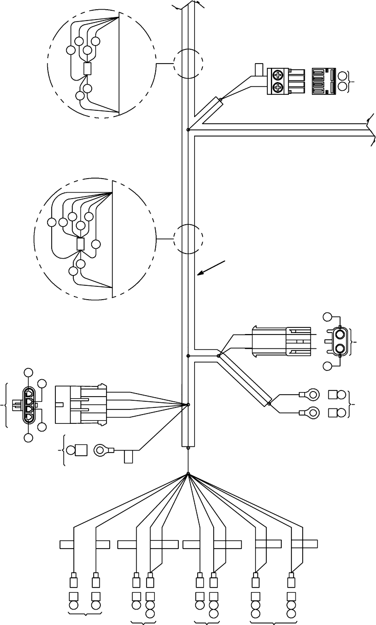
ELECTRICAL WIRE HARNESS GROUP -- SECTION 1 OF 5
C
SWS
KEY
SWITCH
S1
HORN
BUTTON
SW6
FORWARD/
REVERSE
SWITCH
S1
E--STOP
SWITCH
3A
KEYKEY
4
30
A
A
A
A
A
A
A
42C42
35
42A42
HORN
HORN
4A4
5
MOVEMOVE STOPSTOP
5B
45A
ESD
ESD
SS
24 25
14A 15
POWER
WHEEL BRAKE CONNECTOR
OUTPUT
BA
O
N
DCBA
J2
GILL
SENSOR
J
14A
14
14H
14F
14E
14C
14B
14G
WIRE TIE TO
MAIN TRUNK WIRE TIE TO
MAIN TRUNK
42C
42G
42B
42D
42E
42F
J
P10
21
25 24
PROPEL
MOTOR
DETAIL A--A
42A 14
31
32
DETAIL B--B
G
1
20
R14 1032129 REV.01 (12-06)
ELECTRICAL WIRE HARNESS GROUP -- SECTION 2 OF 5
5
5A
6
6A
DI
MAIN
CONTACTOR
1B
1A
50A
D2
CIRCUIT
BREAKER
MTR6
BRUSH HEAD
ACTUATOR
20
19
B
A
ESD
SW1
CHARGER
INTERLOCK
SWITCH
45B C
26 A
4B A
13B C
NEGATIVE
STAND--OFF
GRD COM NO ESD ACT D2 D1
F2
7.5A
B
A
B
APUMP
MOTOR
FUSE
7.5 AMP
CB2CB1
(+)(--)(+)
H1M1M1
A2
A14C
14C
A1A
A4A
4B
A 14D
A21
E5A
E6A
C1B
C2
C 50A
CB #2
15 AMP
CB #1
5AMP
H1
HOUR
METER
M1B
MAIN
COIL
M1A
MAIN
CONTACTOR
POSITIVE
STAND--OFF
TO SEAT
WIRE HARNESS
BAC
BAC
27 42E 13S
DETAIL B--B
ROTATED 90 DEG
CONTINUED
X
X
O
YL
M
U
1
R14 1032129 REV.01 (12-06)
21
ELECTRICAL WIRE HARNESS GROUP -- SECTION 3 OF 5
U1
13E
CONTROL
BOARD
VAC
MOTOR
13D
12A
12
BRUSH
MOTOR
2
1
P9
P8
4
3
2
1
10
9
8
7
35
23
12
1
13
24 CONTROL
BOARD
ESD
C 45 ESD
SOCKET
NO. SOCKET
NO. SOCKET
NO.
WIRE
NO. WIRE
NO. WIRE
NO.
1
2
3
4
5
6
7
8
9
10
11
12
PLUG CAVITY
PLUG CAVITY
PLUG CAVITY
16
6
46
27
29
18
30
47
17
13
14
15
16
17
18
19
20
21
22
23
--
14B
21
23
PLUG CAVITY
5B
26
51
28
20
35
19
--
24
25
26
27
28
29
30
31
32
33
34
35
3
22
PLUG CAVITY
15
PLUG CAVITY
PLUG CAVITY
PLUG CAVITY
PLUG CAVITY
PLUG CAVITY
32
31
42D
P
R
G
DETAIL A--A
ROTATED 90 DEG
CONTINUED DETAIL C--C
1
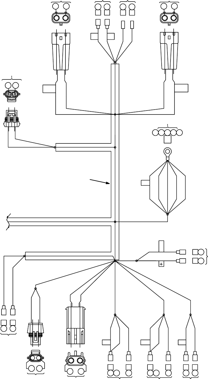
Ref. Part No. Serial Number Description Qty.
11025451 (00000000-- )DHarness, Wire, Main [Readyspace Rider] 1
22
R14 1032129 REV.01 (12-06)
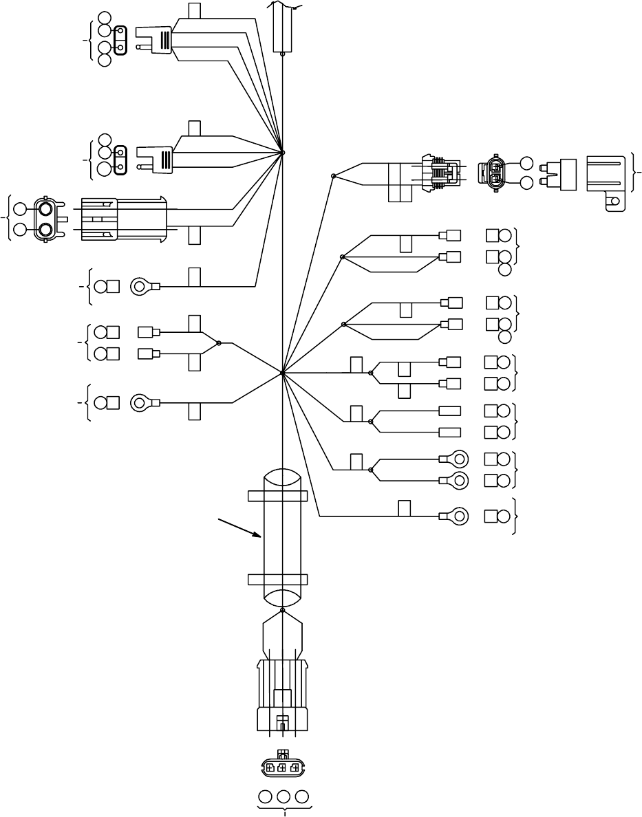
ELECTRICAL WIRE HARNESS GROUP -- SECTION 4 OF 5
DETAIL C--C
ROTATED 90 DEG
CONTINUED DETAIL D--D
MTR2
FRONT
BRUSH MOTOR
MTR3
REAR
BRUSH MOTOR
87
45E
ESD
ESD FRONT (+) REAR (--)
910
BA BA
BA BA
BA
BA
17 18
MTR5
EXTRACT
ACTUATOR
B
O
TT
1
R14 1032129 REV.01 (12-06)
23
ELECTRICAL WIRE HARNESS GROUP -- SECTION 5 OF 5
13D
REVOLVING
LIGHT SWITCH
RECOVERY TANK
LIGHT REVOLVING
READY SPACE
WATER VALVE
SOL 1
12
P3 P2
VAC1 VAC2
ESD
C
ESD
13S 45A 45 45E 45B
23A
14F
A
33 14E 33 13B 13E 12A
AB
AB
AB
AB
AB
28 42F
AB
HORN
EXTFLSHR/S
AB
AB
AA
47 42B
HOSE
SWITCH
S8
42G 29
SOLUTION TANK
LOW SWITCH PUMP
MOTOR
22 48
AB
AA
14H 14J 16 14J 14K 46 14K 51
FLUSH
WATER VALVE
SOL2
EXTRACTOR
SOLENOID
WATER VALVE SOL3
AB
AAAA
HORN
VO
V
TT
RECOVERY TANK
FULL SOLUTION
SWITCH
DETAIL D--D
ROTATED 90 DEG
CONTINUED
VACUUM
MOTOR 1
VACUUM
MOTOR 2
1
24
R14 1032129 REV.01 (12-06)
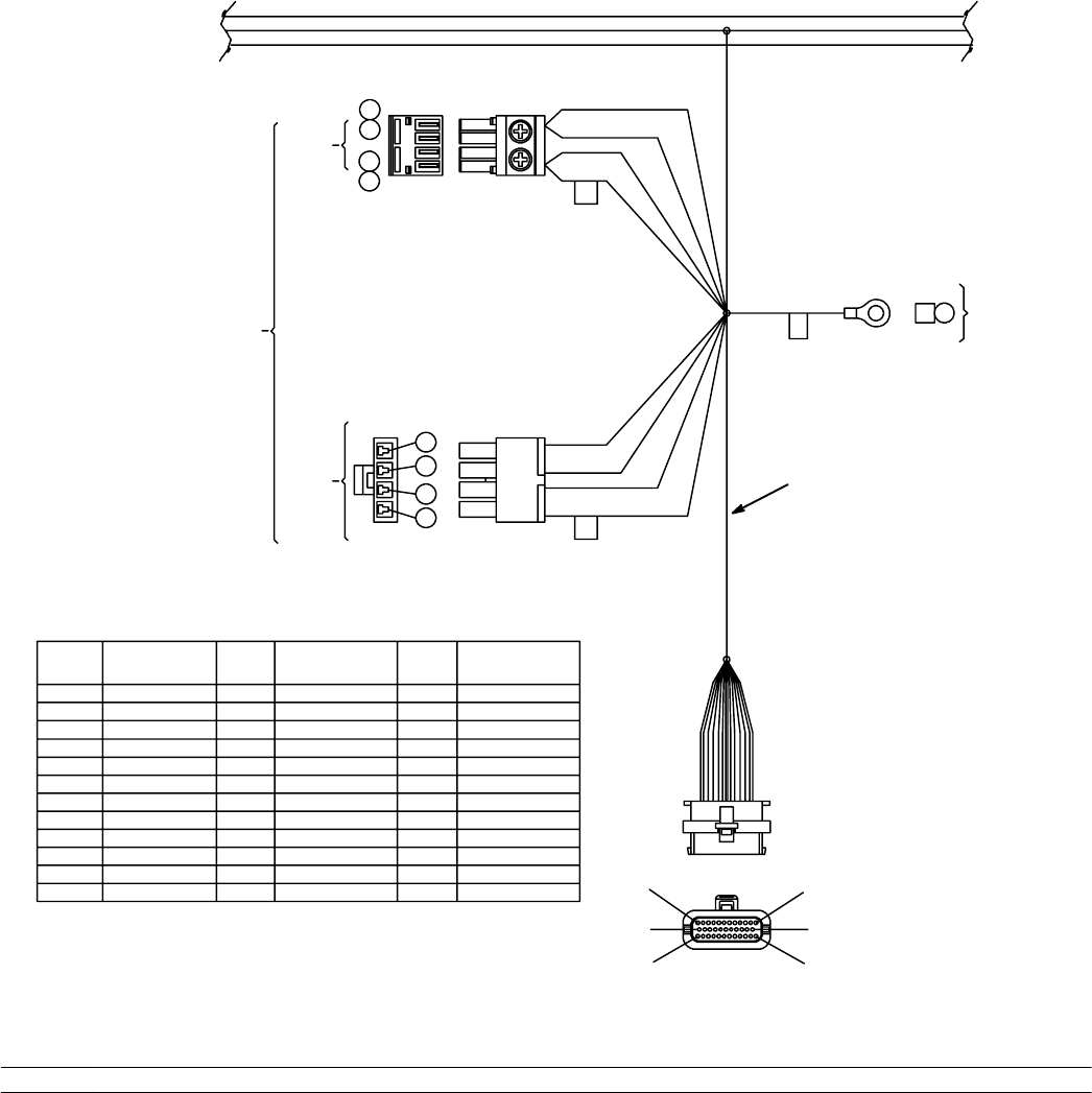
Ref. Part No. Serial Number Description Qty.
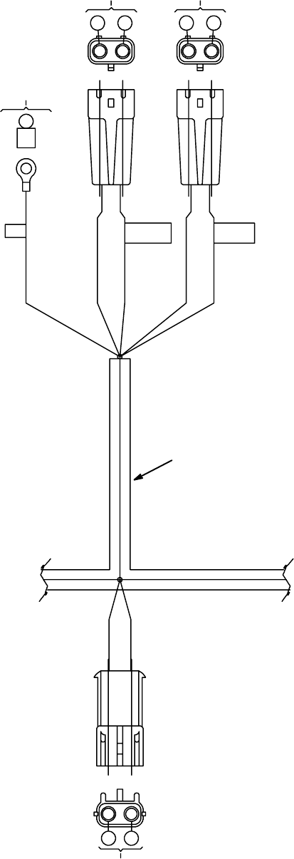
11025451 (00000000-- )DHarness,Seat [ReadySpace Rider] 1
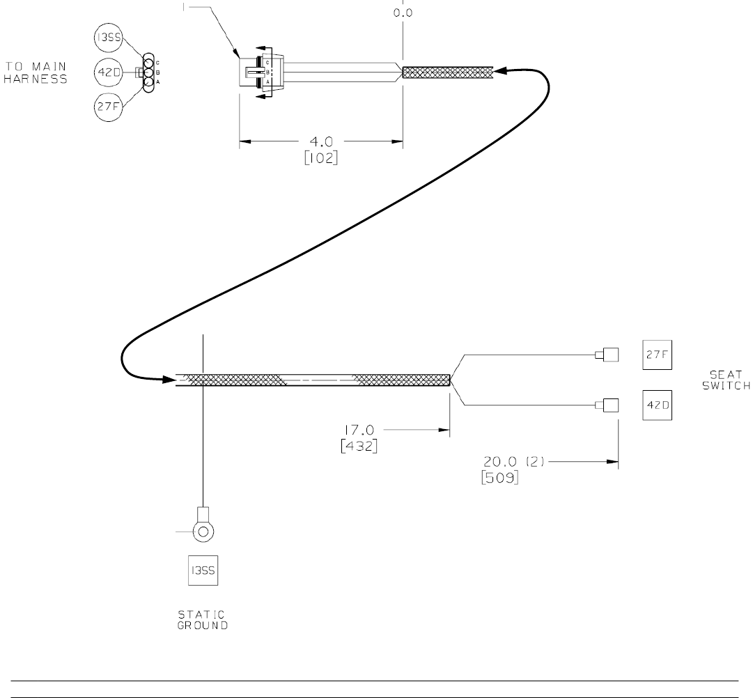
ELECTRICALWIREHARNESSGROUP - SEAT HARNESS
R14 1032129 REV.01 (12-06)
25
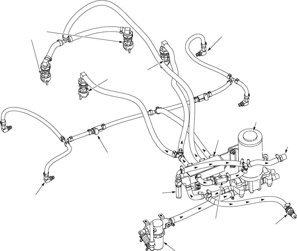
R14 – ReadySpace & Extraction Plumbing Diagram
ReadySpace Nozzles
GREEN CAPS (2)
Tip #11002
Restorative
Extraction Nozzles
WHITE CAPS (2)
Tip #11006E
Accessory
Tool Solution
Hose Coupler
Solution Tank
Filter Assy.
p
Solution Pump
Relief Valve
Solution
Tank
Return
Solution Flush Line
Disconnect Coupler
ReadySpace Vacuum Shoe
Solution Flush Line Spray Tips
Hose Assy RH
ReadySpace Vacuum Shoe
Solution Flush Line Spray Tips
Hose Assy LH
Solution
Solenoids
Check Valve
26
R14 1032129 REV.01 (12-06)
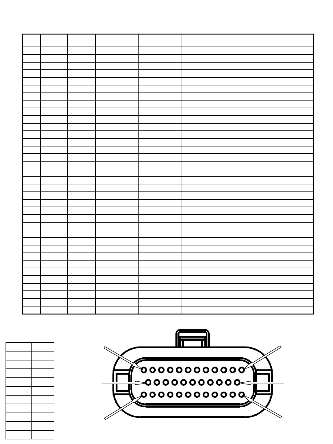
R14 – Main Harness to Control Board 35 Pin Connector Detail
Wiring Color Codes
(Unless otherwise marked)
0
1
2
3
4
5
6
7
8
9
Tan
Pink
Brown
Orange
Yellow
Green
Blue
Purple
Gray
White
Right Most Digit
of Wire Number Color of Wire
Viewed from front (plug-in)
side of harness connector
Pin 1
Pin 24
Pin 35
Pin 12
Pin 13
Pin 23
pin # wire #
input or
output active
voltage inactive voltage
1empty x x x
2empty x x x
3empty x x x
4 16 output B- B+ SOL1 ReadySpace solenoid valve
5 6 output B- B+ M1A Main contactor
6 46 output B- B+ SOL3 ReadySpace flush solenoid valve
7 27 input B- open SW2 Seat switch
8 29 input B- open SW4 Solution tank low switch
9 18 output B+ or B- open MTR5 Extractor shoes actuator
10 30 input B- open S2 Horn switch
11 47 input B- open SW8 Hose switch
12 17 output B+ or B- open MTR5 Extractor shoes actuator
13 14B input B+ open Fly back path
14 21 output B- B+ H1 Hour meter
15 23 output B- B+ LS1 Horn
16 empty x x x
17 5B input B+ open Battery positive power supply
18 26 input open B+ SW1 Battery charger interlock switch
19 51 output B- B+ SOL2 Extraction solenoid
20 28 input B- open SW3 Recovery tank full switch
21 20 output B+ or B- open MTR6 Scrub head actuator
22 35 input B- open SW6 Reverse switch
23 19 output B+ or B- open MTR6 Scrub head actuator
24 3 input B+ open SW5 Key switch
25 22 output B- B+ MTR7 Solution pump motor
26 empty x x x
27 15 output B- B+ MTR1B Parking brake solenoid
28 empty x x x
29 empty x x x
30 empty x x x
31 empty x x x
32 empty x x x
33 32 input 1.5 to 4.0V less than 1.5V U2 Brake input signal
34 31 input 1.3 to 4.0V less than 1.3V U2 Throttle signal input
35 42D output B- open Switches & sensors battery negative
function/component
x
x
x
x
x
x
x
x
x
x
R14 1032129 REV.01 (12-06)
27
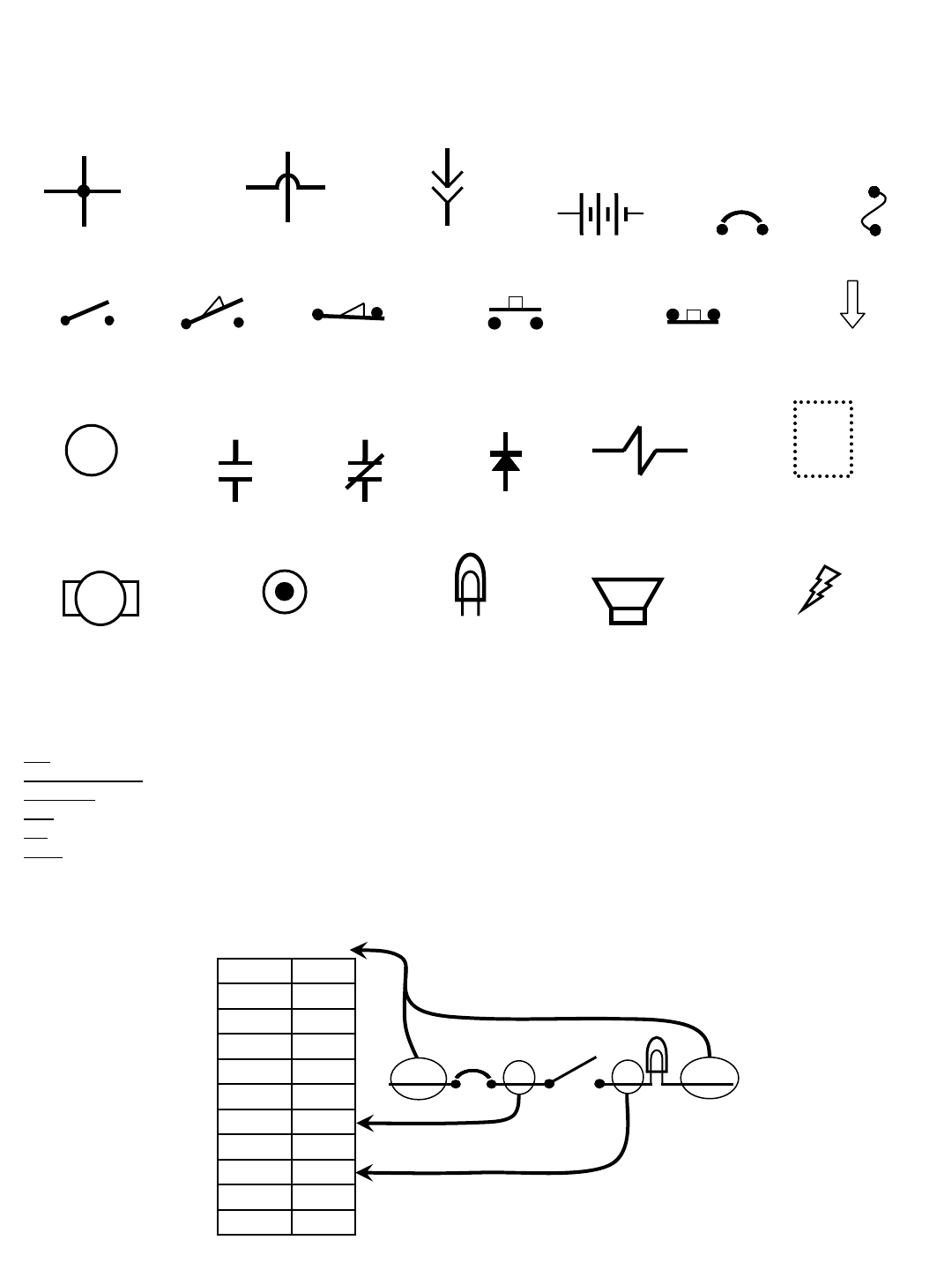
Commonly Used Electrical Symbols & Terms
+-
Battery Fuse
Normally Closed
Push-Button Switch
Normally Open
Switch
M1
Relay Coil
(Part 1 of Relay)
Circuit Breaker
Motor
Solenoid (Valve
or Actuator)
Horn or Alarm
Lamp
(Light Bulb)
Wires Connected
Together
Normally Open
Push-Button Switch
Wiring Color Codes
(Unless otherwise marked)
0
1
2
3
4
5
6
7
8
9
Tan
Pink
Brown
Orange
Yellow
Green
Blue
Purple
Gray
White
Right Most Digit
of Wire Number Color of Wire
Example of Wiring Numbers & Colors:
1 RED 25 7 13 BLK
Relay Contacts (Part 2 of Relay)
Normally Open Normally Closed
Normally Open
Limit Switch Normally Closed
Limit Switch
Indicates Component
is Energized
Plug-in
Connection
NOTE: The term “NORMALLY” refers to the components’ “at rest” or “de-energized” position
Diode
Wires Not
Connected Together
Terms & Abbreviations
BDI – Battery Discharge Indicator
Dynamic Braking – A method of using the generating nature of an electric motor to slow the machine
Hall Effect – A voltage developed as a result of current flow in the presence of a magnetic field
LED – Light Emitting Diode
PM – Permanent Magnet
PWM (Pulse Width Modulation) – A method of using controlled on/off times to regulate the voltage and current supplied to an
electrical device
Indicates Movement
from Normal Position
Indicates Component in
Position Other than Normal
Wiring Standoff
(Connection Point)
28
R14 1032129 REV.01 (12-06)
D2
1 RED 13 BLK
13 BLK
POS
RIBBON CABLE CONNECTOR P6
CONTROL BOARD
STANDOFF 2
+-
6 VDC +-
6 VDC +-
6 VDC +-
6 VDC
M1B
1 RED
1 RED
CHARGER
PLUG
STANDOFF 1
13 BLK
NEG
TOUCH
PANEL
50 RED
S1
M1A
D1
KEYSWITCH
RIBBON CABLE
-
EMERGENCY STOP
SWITCH (E-STOP)
50 RED
2214
MAIN
CONTACTOR
6
55
56
3
26
3
4
4
44
PIN J6-17
PIN J6-5
PIN J6-24
PIN J6-18
PIN J6-13
14
1 RED
1 RED 13 BLK
POST J11 POST J7
SW1
Wiring Color Codes
(Unless otherwise marked)
0
1
2
3
4
5
6
7
8
9
Tan
Pink
Brown
Orange
Yellow
Green
Blue
Purple
Gray
White
Right Most Digit
of Wire Number Color of Wire
= Battery Negative
or Logic Ground
= Battery Positive
or Positive Output
CB1
5 A
CB2
15 A
+
F1
100 A SW5
LEFT SIDE
DASH PANEL
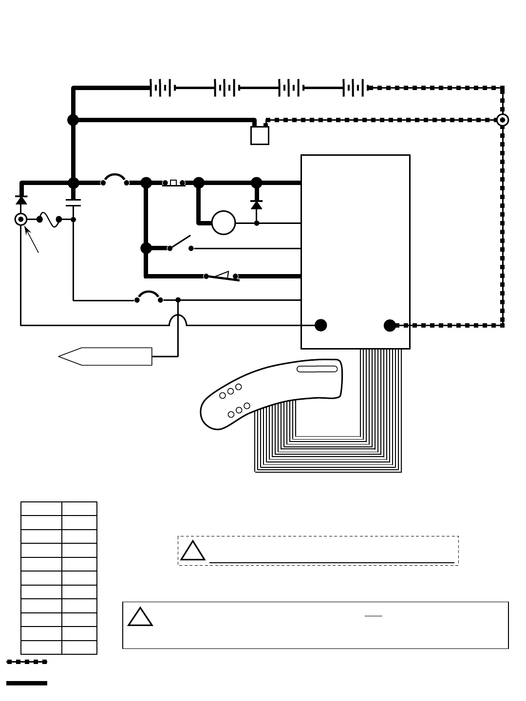
R14 - Key OFF Power Distribution
CONDITIONS: Key OFF, battery charger NOT CONNECTED to charger plug
FLYBACK PATH
CHARGER
INTERLOCK
TO CB2 PROTECTED
COMPONENTS
14
!Be cautious when working near Control Board -
Battery voltage is always present, even with Key OFF
If Charger Plug is connected to battery charger, ALL machine functions will be
disabled when Key Switch is turned ON
The Flyback Path prevents high voltage spikes when a component is turned OFF
i
R14 1032129 REV.01 (12-06)
29
D2
1 RED 13 BLK
13 BLK
POS
RIBBON CABLE CONNECTOR P6
CONTROL BOARD
STANDOFF 2
+-
6 VDC +-
6 VDC +-
6 VDC +-
6 VDC
M1B
1 RED
1 RED
CHARGER
PLUG
STANDOFF 1
13 BLK
NEG
TOUCH
PANEL
50 RED
S1
M1A
D1
KEYSWITCH
RIBBON CABLE
-
50 RED
2214
MAIN
CONTACTOR
6
55
56
3
26
3
26
4
4
44
PIN J6-17
PIN J6-5
PIN J6-24
PIN J6-18
PIN J6-13
14
1 RED
1 RED 13 BLK
POST J11 POST J7
SW1
Wiring Color Codes
(Unless otherwise marked)
0
1
2
3
4
5
6
7
8
9
Tan
Pink
Brown
Orange
Yellow
Green
Blue
Purple
Gray
White
Right Most Digit
of Wire Number Color of Wire
= Battery Negative
or Logic Ground
= Battery Positive
or Positive Output
CB1
5 A
CB2
15 A
+
F1
100 A SW5
CHARGER
INTERLOCK
LEFT SIDE
DASH PANEL
R14 - Key OFF Power Distribution
CONDITIONS: Key OFF, battery charger CONNECTED to charger plug
TO CB2 PROTECTED
COMPONENTS
14
!Be cautious when working near Control Board -
Battery voltage is always present, even with Key OFF
FLYBACK PATH
If Charger Plug is connected to battery charger, ALL machine functions will be
disabled when Key Switch is turned ON
The Flyback Path prevents high voltage spikes when a component is turned OFF
i
EMERGENCY STOP
SWITCH (E-STOP)
30
R14 1032129 REV.01 (12-06)
D2
1 RED 13 BLK
13 BLK
POS
RIBBON CABLE CONNECTOR P6
CONTROL BOARD
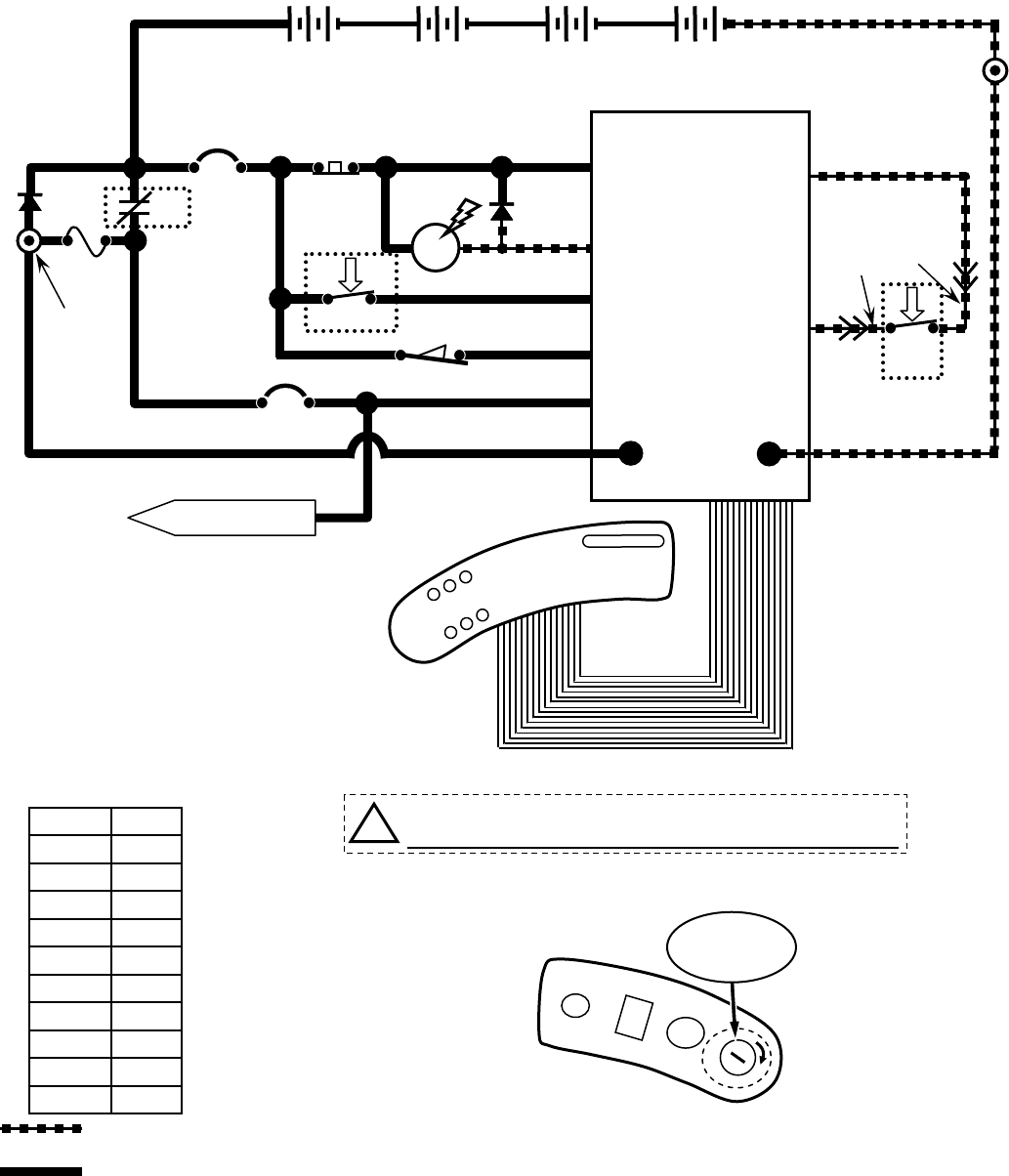
R14 - Key ON, Operator on Seat
STANDOFF 2
+-
6 VDC +-
6 VDC +-
6 VDC +-
6 VDC
M1B
1 RED
STANDOFF 1
NEG
TOUCH
PANEL
50 RED
S1
M1A
D1
KEYSWITCH
RIBBON CABLE
-
50 RED
2214
MAIN CONTACTOR
6
55
56
3
26
3
4
4
44
PIN J6-17
PIN J6-5
PIN J6-24
PIN J6-18
PIN J6-13
14
1 RED
POST J11 POST J7
SW1
PIN J6-35
PIN J6-7
42
42
27
LOGIC GROUND
32
ORG
27
GRN
Wiring Color Codes
(Unless otherwise marked)
0
1
2
3
4
5
6
7
8
9
Tan
Pink
Brown
Orange
Yellow
Green
Blue
Purple
Gray
White
Right Most Digit
of Wire Number Color of Wire
= Battery Negative
or Logic Ground
= Battery Positive
or Positive Output
CB1
5 A
CB2
15 A
+
F1
100 A
SW5
RIGHT SIDE
DASH PANEL
O
I
SW2
SEAT
SWITCH
LEFT SIDE
DASH PANEL
FLYBACK PATH
CHARGER
INTERLOCK
TO CB2 PROTECTED
COMPONENTS
14
!Be cautious when working near Control Board -
Battery voltage is always present, even with Key OFF
EMERGENCY STOP
SWITCH (E-STOP)
KEY
SWITCH
ON
R14 1032129 REV.01 (12-06)
31
D2
14
13 BLK
POS
RIBBON CABLE CONNECTOR P6
CONTROL BOARD
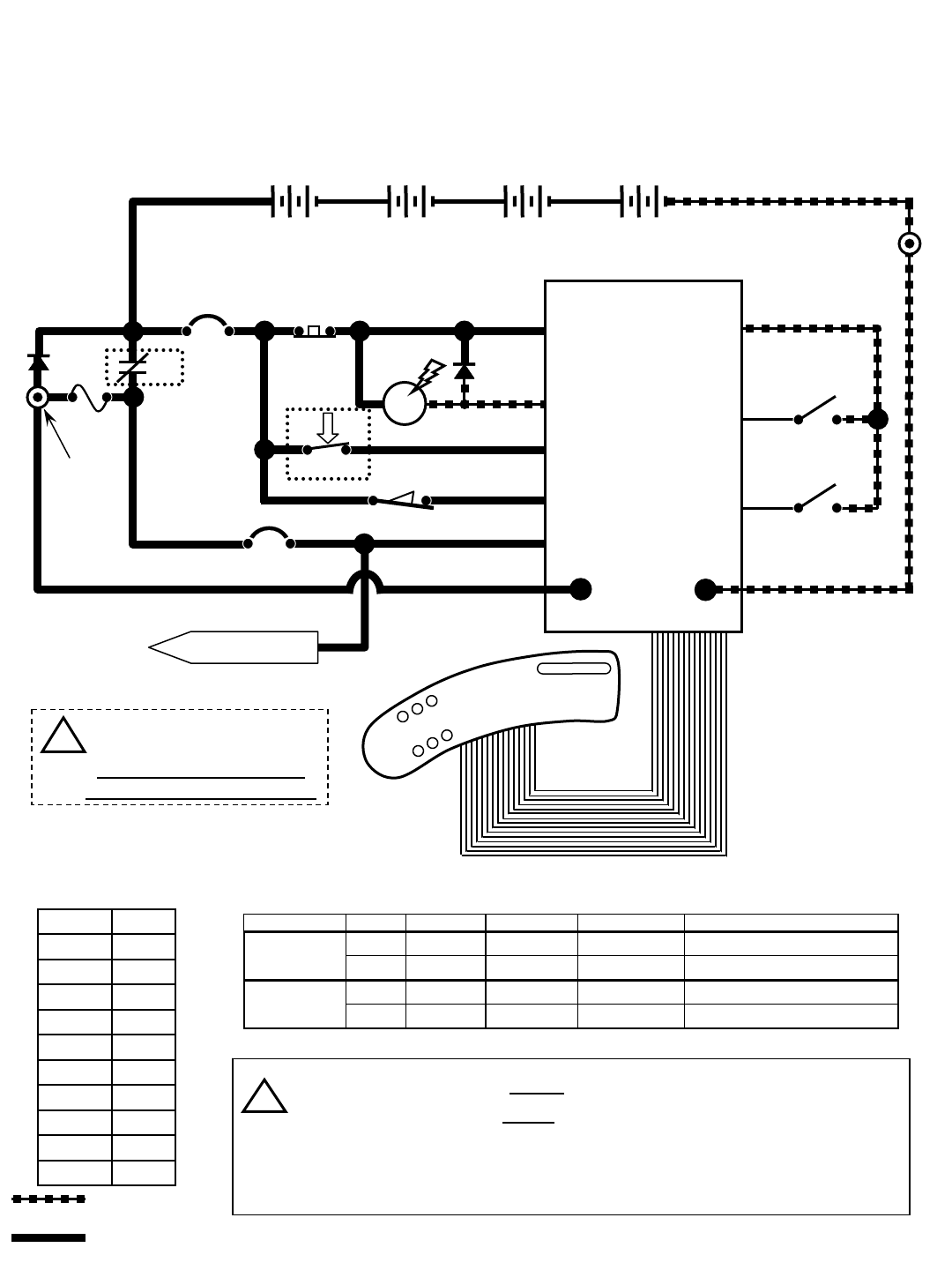
R14 - Tank Level Switches
STANDOFF 2
M1B
1 RED
NEG
TOUCH
PANEL
50 RED
S1
M1A
D1
KEYSWITCH
RIBBON CABLE
-
50 RED
2214
MAIN CONTACTOR
6
55
56
3
26
3
4
4
44
PIN J6-17
PIN J6-5
PIN J6-24
PIN J6-18
PIN J6-13
14
1 RED
POST J11 POST J7
Wiring Color Codes
(Unless otherwise marked)
0
1
2
3
4
5
6
7
8
9
Tan
Pink
Brown
Orange
Yellow
Green
Blue
Purple
Gray
White
Right Most Digit
of Wire Number Color of Wire
= Battery Negative
or Logic Ground
= Battery Positive
or Positive Output
CB1
5 A
CB2
15 A
+
F1
100 A
SW5
CONDITIONS: Key ON, operator on seat
28
29
42
42
RECOVERY TANK
FULL SWITCH
LOGIC GROUND
42
PIN J6-20
PIN J6-35
PIN J6-8
SOLUTION TANK
LOW SWITCH
SW3
SW4
switch tank full tank empty switch OPEN switch CLOSED indicator
xx
Solution Tank Empty LED OFF
xx
Solution Tank Empty LED ON
xx
Recovery Tank Full LED ON
xx
Recovery Tank Full LED OFF
Solution Tank
Recovery Tank
Tank Level Switches Logic Chart
Recovery Tank Full Switch closes when recovery tank is full
Solution Tank Low Switch opens when solution tank is low
Tank Level Switches are ALWAYS in the OPEN position with low or
empty tank
Tank Level Switches are ALWAYS in the CLOSED position with full tank
i
LEFT SIDE
DASH PANEL
1 RED 13 BLK
+-
6 VDC +-
6 VDC +-
6 VDC +-
6 VDC
STANDOFF 1
SW1 CHARGER
INTERLOCK
FLYBACK PATH
TO CB2 PROTECTED
COMPONENTS
14
!Be cautious when working
near Control Board -
Battery voltage is always
present, even with Key OFF
EMERGENCY STOP
SWITCH (E-STOP)
32
R14 1032129 REV.01 (12-06)
D2
14
13 BLK
POS
RIBBON CABLE CONNECTOR P6
CONTROL BOARD
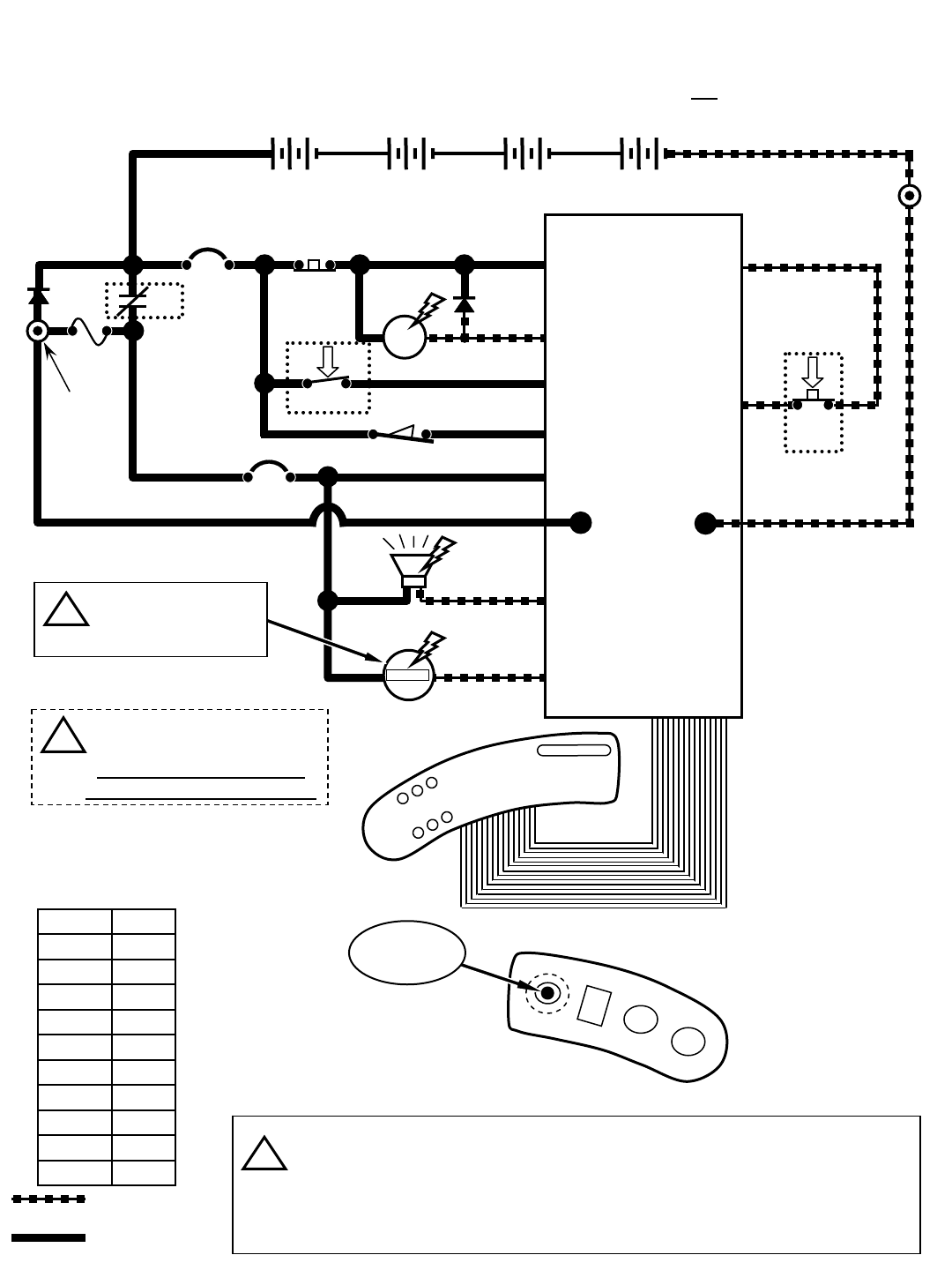
R14 - Horn & Hour Meter
STANDOFF 2
M1B
1 RED
NEG
TOUCH
PANEL
50 RED
S1
M1A
D1
KEYSWITCH
RIBBON CABLE
-
50 RED
2214
MAIN CONTACTOR
6
55
56
3
26
3
4
4
44
PIN J6-17
PIN J6-5
PIN J6-24
PIN J6-18
PIN J6-13
14
1 RED
POST J11 POST J7
Wiring Color Codes
(Unless otherwise marked)
0
1
2
3
4
5
6
7
8
9
Tan
Pink
Brown
Orange
Yellow
Green
Blue
Purple
Gray
White
Right Most Digit
of Wire Number Color of Wire
= Battery Negative
or Logic Ground
= Battery Positive
or Positive Output
CB1
5 A
CB2
15 A
+
F1
100 A
SW5
CONDITIONS (Horn): Key ON, horn switch depressed
CONDITIONS (Hour Meter): Key ON, operator on seat, Propel Pedal depressed OR Vacuum Fan running
30
42
PIN J6-35 LOGIC GROUND
42
PIN J6-10 S2
HORN
SWITCH
HORN
HOUR
METER
23
14
14
21
LS1
00000
H1
Hour Meter is active only
when propelling (forward
or reverse), OR anytime
Vacuum Fans are ON
LEFT SIDE
DASH PANEL
Horn pulses ON & OFF when Directional Switch is in REVERSE
Hour Meter is ON only when propelling (forward or reverse), or anytime
Vacuum Fans are ON
Horn pulses when a fault is detected (Directional Switch must be in FORWARD
Position) – refer to “Diagnostic/Beep Code” chart
i
RIGHT SIDE
DASH PANEL
HORN
SWITCH
23
21
PIN J6-15
PIN J6-14
1 RED 13 BLK
+-
6 VDC +-
6 VDC +-
6 VDC +-
6 VDC
STANDOFF 1
SW1 CHARGER
INTERLOCK
FLYBACK PATH
!Be cautious when working
near Control Board -
Battery voltage is always
present, even with Key OFF
i
EMERGENCY STOP
SWITCH (E-STOP)
R14 1032129 REV.01 (12-06)
33
D2
POS
RIBBON CABLE CONNECTOR P6
CONTROL BOARD
R14 - Propel Forward System
STANDOFF 2
M1B
1 RED
NEG
TOUCH
PANEL
50 RED
S1
M1A
D1
KEYSWITCH
RIBBON CABLE
-
50 RED
214
MAIN CONTACTOR
6
55
56
3
26
3
4
4
44
PIN J6-17
PIN J6-5
PIN J6-24
PIN J6-18
PIN J6-13
14
1 RED
POST J11
POST J7
Wiring Color Codes
(Unless otherwise marked)
0
1
2
3
4
5
6
7
8
9
Tan
Pink
Brown
Orange
Yellow
Green
Blue
Purple
Gray
White
Right Most Digit
of Wire Number Color of Wire
= Battery Negative
or Logic Ground
= Battery Positive
or Positive Output
CB1
5 A
CB2
15 A
+
F1
100 A
SW5
CONDITIONS: Key ON, operator on seat, directional switch in FORWARD position, propel pedal depressed
14
LEFT SIDE
DASH PANEL
13 BLK
27
42
42
LOGIC GROUND
PROPEL PEDAL
POSITION SENSOR
31 PROPEL
SIGNAL
INPUT
POWER
GND 42
14
X
35
PROPEL
DIRECTION
SWITCH
42
FWD
PIN J6-7
PIN J6-35
PIN J6-34
PIN J6-22
32
ORG
27
GRN
SW6
SW2
SEAT
SWITCH
42
PROPEL MOTOR
FORWARD
25 RED
24 BLK
MTR1A
1515
PIN J10-2
PIN J10-1
PIN J6-27
MTR1B
BRAKE
SOLENOID
14
14 14
24 BLK
i
FORWARD
REVERSE
RIGHT SIDE
DASH PANEL
DIRECTIONAL
SWITCH
Typical Propel Motor Current Draw: 1 to 20 Amps in motion, higher at start-up
Propel Motor Voltage: 0 to 24 VDC - FORWARD
0 to approx. 17 VDC - REVERSE
Propel Motor is controlled by PWM (Pulse Width Modulation)
The Propel Pedal Position HALL EFFECT Sensor sends a varying voltage
signal (1 to 4 Volts) to control board, based upon position of the propel pedal
Brake Solenoid is
energized to release
parking brake.
Refer to the “Propel/Brake
Diagnostics” page for more
information
HALL
EFFECT
SENSOR
U2
1 RED 13 BLK
+-
6 VDC +-
6 VDC +-
6 VDC +-
6 VDC
STANDOFF 1
SW1 CHARGER
INTERLOCK
FLYBACK PATH
!Be cautious when working
near Control Board -
Battery voltage is always
present, even with Key OFF
i
i
EMERGENCY STOP
SWITCH (E-STOP)
34
R14 1032129 REV.01 (12-06)
D2
POS
RIBBON CABLE CONNECTOR P6
CONTROL BOARD
R14 - Propel Reverse System
STANDOFF 2
M1B
1 RED
NEG
TOUCH
PANEL
50 RED
S1
M1A
D1
KEYSWITCH
RIBBON CABLE
-
50 RED
214
MAIN CONTACTOR
6
55
56
3
26
3
4
4
44
PIN J6-17
PIN J6-5
PIN J6-24
PIN J6-18
PIN J6-13
14
1 RED
POST J11
POST J7
Wiring Color Codes
(Unless otherwise marked)
0
1
2
3
4
5
6
7
8
9
Tan
Pink
Brown
Orange
Yellow
Green
Blue
Purple
Gray
White
Right Most Digit
of Wire Number Color of Wire
= Battery Negative
or Logic Ground
= Battery Positive
or Positive Output
CB1
5 A
CB2
15 A
+
F1
100 A
SW5
CONDITIONS: Key ON, operator on seat, directional switch in REVERSE position, propel pedal depressed
14
LEFT SIDE
DASH PANEL
13 BLK
27
42
42
LOGIC GROUND
PROPEL PEDAL
POSITION SENSOR
31 POWER
GND 42
14
X
35
PROPEL
DIRECTION
SWITCH
42
REV
PIN J6-7
PIN J6-35
PIN J6-34
PIN J6-22
32
ORG
27
GRN
SW6
SW2
SEAT
SWITCH
HALL
EFFECT
SENSOR
U2
42
PROPEL MOTOR
FORWARD
25 RED
24 BLK
MTR1A
1515
PIN J10-2
PIN J10-1
PIN J6-27
MTR1B
BRAKE
SOLENOID
14
14 14
24 BLK
FORWARD
REVERSE
RIGHT SIDE
DASH PANEL
PROPEL
SIGNAL
INPUT
1 RED 13 BLK
+-
6 VDC +-
6 VDC +-
6 VDC +-
6 VDC
STANDOFF 1
SW1 CHARGER
INTERLOCK
FLYBACK PATH
DIRECTIONAL
SWITCH
!Be cautious when working
near Control Board -
Battery voltage is always
present, even with Key OFF
Brake Solenoid is
energized to release
parking brake.
Refer to the “Propel/Brake
Diagnostics” page for more
information
i
i
i
Typical Propel Motor Current Draw: 1 to 20 Amps in motion, higher at start-up
Propel Motor Voltage: 0 to 24 VDC - FORWARD
0 to approx. 17 VDC - REVERSE
Propel Motor is controlled by PWM (Pulse Width Modulation)
The Propel Pedal Position HALL EFFECT Sensor sends a varying voltage
signal (1 to 4 Volts) to control board, based upon position of the propel pedal
EMERGENCY STOP
SWITCH (E-STOP)
R14 1032129 REV.01 (12-06)
35
D2
POS
RIBBON CABLE CONNECTOR P6
CONTROL BOARD
R14 – Braking System
STANDOFF 2
M1B
1 RED
NEG
TOUCH
PANEL
50 RED
S1
M1A
D1
KEYSWITCH
RIBBON CABLE
-
50 RED
214
MAIN CONTACTOR
6
55
56
3
26
3
4
4
44
PIN J6-17
PIN J6-5
PIN J6-24
PIN J6-18
PIN J6-13
14
1 RED
POST J11 POST J7
Wiring Color Codes
(Unless otherwise marked)
0
1
2
3
4
5
6
7
8
9
Tan
Pink
Brown
Orange
Yellow
Green
Blue
Purple
Gray
White
Right Most Digit
of Wire Number Color of Wire
= Battery Negative
or Logic Ground
= Battery Positive
or Positive Output
CB1
5 A
CB2
15 A
+
F1
100 A
SW5
CONDITIONS: Key ON, operator on seat, brake pedal depressed
14
LEFT SIDE
DASH PANEL
13 BLK
27
42
42
LOGIC GROUND
BRAKE PEDAL
POSITION SENSOR
32 POWER
GND 42
14
PIN J6-7
PIN J6-35
PIN J6-33
32
ORG
27
GRN
SW2
SEAT
SWITCH
HALL
EFFECT
SENSOR
U2
42
PROPEL MOTOR
FORWARD
25 RED
24 BLK MTR1A
1515
PIN J10-2
PIN J10-1
PIN J6-27
MTR1B
BRAKE
SOLENOID
14
14 14
24 BLK
The brake pedal position HALL EFFECT sensor sends a varying voltage
signal (1 to 4 Volts) to control board, based upon position of the brake pedal
Brake Solenoid is DE-energized to apply parking brake.
Dynamic Braking will occur before Brake Solenoid is de-energized.
Refer to the “Propel/Brake Diagnostics” page for more information
i
BRAKE
SIGNAL
INPUT
1 RED 13 BLK
+-
6 VDC +-
6 VDC +-
6 VDC +-
6 VDC
STANDOFF 1
SW1 CHARGER
INTERLOCK
FLYBACK PATH
!Be cautious when working near Control Board -
Battery voltage is always present, even with Key OFF
Brake Solenoid is
DE-energized to
apply parking brake.
i
EMERGENCY STOP
SWITCH (E-STOP)
36
R14 1032129 REV.01 (12-06)
D2
POS
RIBBON CABLE CONNECTOR P6
CONTROL BOARD
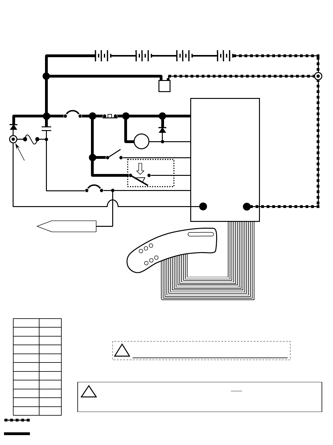
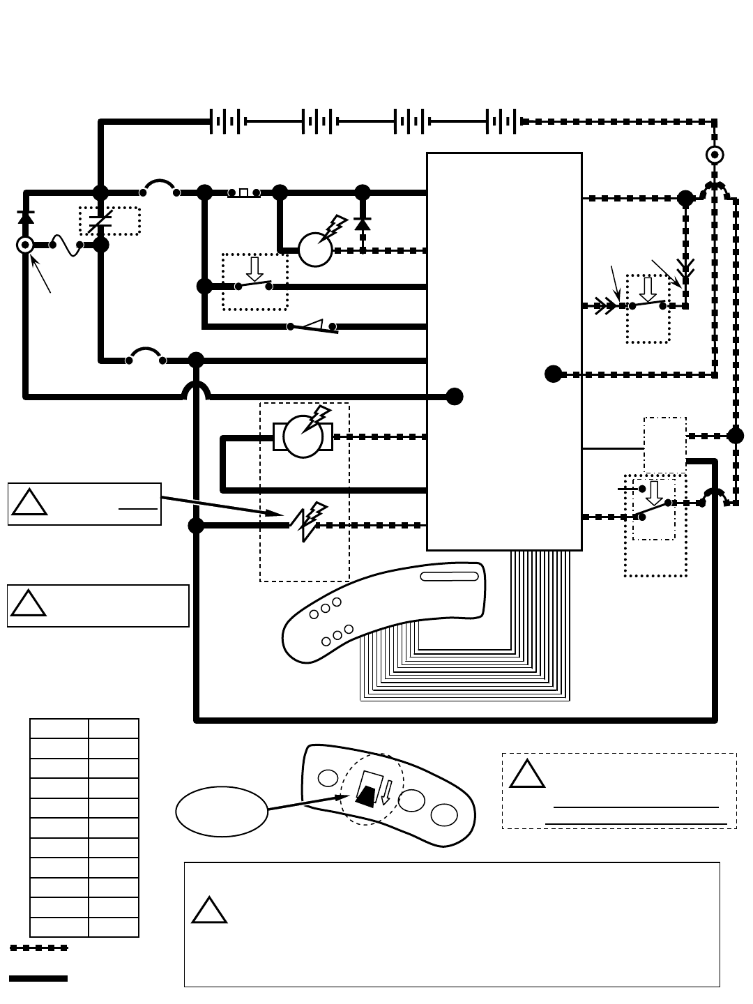
R14 – Lower Scrub Head (ReadySpace Mode)
STANDOFF 2
M1B
1 RED
NEG
TOUCH
PANEL
50 RED
S1
M1A
D1
KEYSWITCH
RIBBON CABLE
-
50 RED
214
MAIN CONTACTOR
6
55
56
3
26
3
4
4
44
PIN J6-17
PIN J6-5
PIN J6-24
PIN J6-18
PIN J6-13
14
1 RED
POST J11 POST J7
Wiring Color Codes
(Unless otherwise marked)
0
1
2
3
4
5
6
7
8
9
Tan
Pink
Brown
Orange
Yellow
Green
Blue
Purple
Gray
White
Right Most Digit
of Wire Number Color of Wire
= Battery Negative
or Logic Ground
= Battery Positive
or Positive Output
CB1
5 A
CB2
15 A
+
F1
100 A
SW5
CONDITIONS: Key ON, operator on seat, ReadySpace button activated
LEFT SIDE
DASH PANEL
13 BLK
47
42
42
LOGIC GROUND
PIN J6-11
PIN J6-35
17
18 MTR5 PIN J6-12
PIN J6-9
EXTRACTOR VACUUM
SHOE ACTUATOR 18
1 RED 13 BLK
+-
6 VDC +-
6 VDC +-
6 VDC +-
6 VDC
STANDOFF 1
SW1 CHARGER
INTERLOCK
FLYBACK PATH
19
20
MTR6 PIN J6-23
PIN J6-21
20 SW8
HOSE
SWITCH
OPEN =
ReadySpace
mode
TO CB2 PROTECTED
COMPONENTS
14
SCRUB HEAD
ACTUATOR
ReadySpace
Mode Button
Scrub Head actuator travel is controlled by monitoring actuator current
In upward travel and brush motor current in downward travel
Hose Switch is OPEN when ReadySpace hose is attached
Hose Switch is CLOSED when Extraction hose is attached
Either hose can be attached when using the Wand tool or when
transporting machine (not cleaning)
i
Actuator voltage switches
polarity when direction of
actuator travel changes
Brush Pressure
Button
!Be cautious when working near Control Board -
Battery voltage is always present, even with Key OFF
i
EMERGENCY STOP
SWITCH (E-STOP)
R14 1032129 REV.01 (12-06)
37
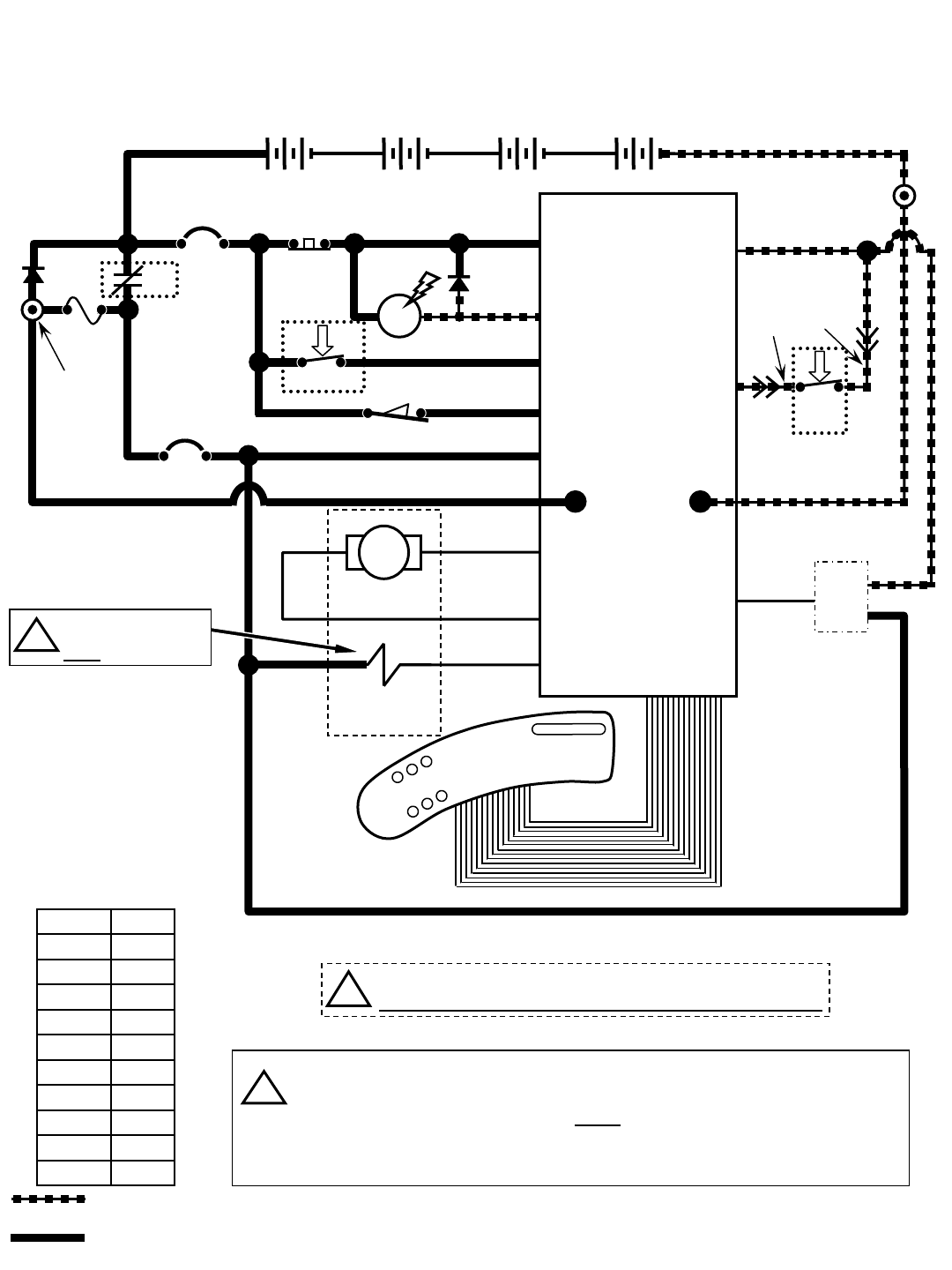
R14 – Lower Scrub Head & Vacuum Shoes (Extraction Mode)
Wiring Color Codes
(Unless otherwise marked)
0
1
2
3
4
5
6
7
8
9
Tan
Pink
Brown
Orange
Yellow
Green
Blue
Purple
Gray
White
Right Most Digit
of Wire Number Color of Wire
= Battery Negative
or Logic Ground
= Battery Positive
or Positive Output
CONDITIONS: Key ON, operator on seat, Extraction button activated
D2
POS
RIBBON CABLE CONNECTOR P6
CONTROL BOARD
STANDOFF 2
M1B
1 RED
NEG
TOUCH
PANEL
50 RED
S1
M1A
D1
KEYSWITCH
RIBBON CABLE
-
50 RED
214
MAIN CONTACTOR
6
55
56
3
26
3
4
4
44
PIN J6-17
PIN J6-5
PIN J6-24
PIN J6-18
PIN J6-13
14
1 RED
POST J11 POST J7
CB1
5 A
CB2
15 A
+
F1
100 A
SW5
LEFT SIDE
DASH PANEL
13 BLK
47
42
42
LOGIC GROUND
PIN J6-11
PIN J6-35
17
18
MTR5 PIN J6-12
PIN J6-9
EXTRACTOR VACUUM
SHOE ACTUATOR 18
1 RED 13 BLK
+-
6 VDC +-
6 VDC +-
6 VDC +-
6 VDC
STANDOFF 1
SW1 CHARGER
INTERLOCK
FLYBACK PATH
19
20
MTR6 PIN J6-23
PIN J6-21
20
CLOSED =
Extraction
mode
TO CB2 PROTECTED
COMPONENTS
14
SCRUB HEAD
ACTUATOR SW8
HOSE
SWITCH
Extraction
Mode Button
Only one actuator will be energized at any given time
Extractor Vacuum Shoe actuator uses internal limit switches to stop
travel in upward and downward travel
Scrub Head actuator travel is controlled by monitoring actuator current in
upward travel and brush motor current in downward travel
Hose Switch is OPEN when ReadySpace hose is attached
Hose Switch is CLOSED when Extraction hose is attached
Either hose can be attached when using the Wand tool or when
transporting machine (not cleaning)
i
Brush Pressure
Button
!Be cautious when working near Control Board -
Battery voltage is always present, even with Key OFF
Actuator voltage switches
polarity when direction of
actuator travel changes
i
EMERGENCY STOP
SWITCH (E-STOP)
38
R14 1032129 REV.01 (12-06)
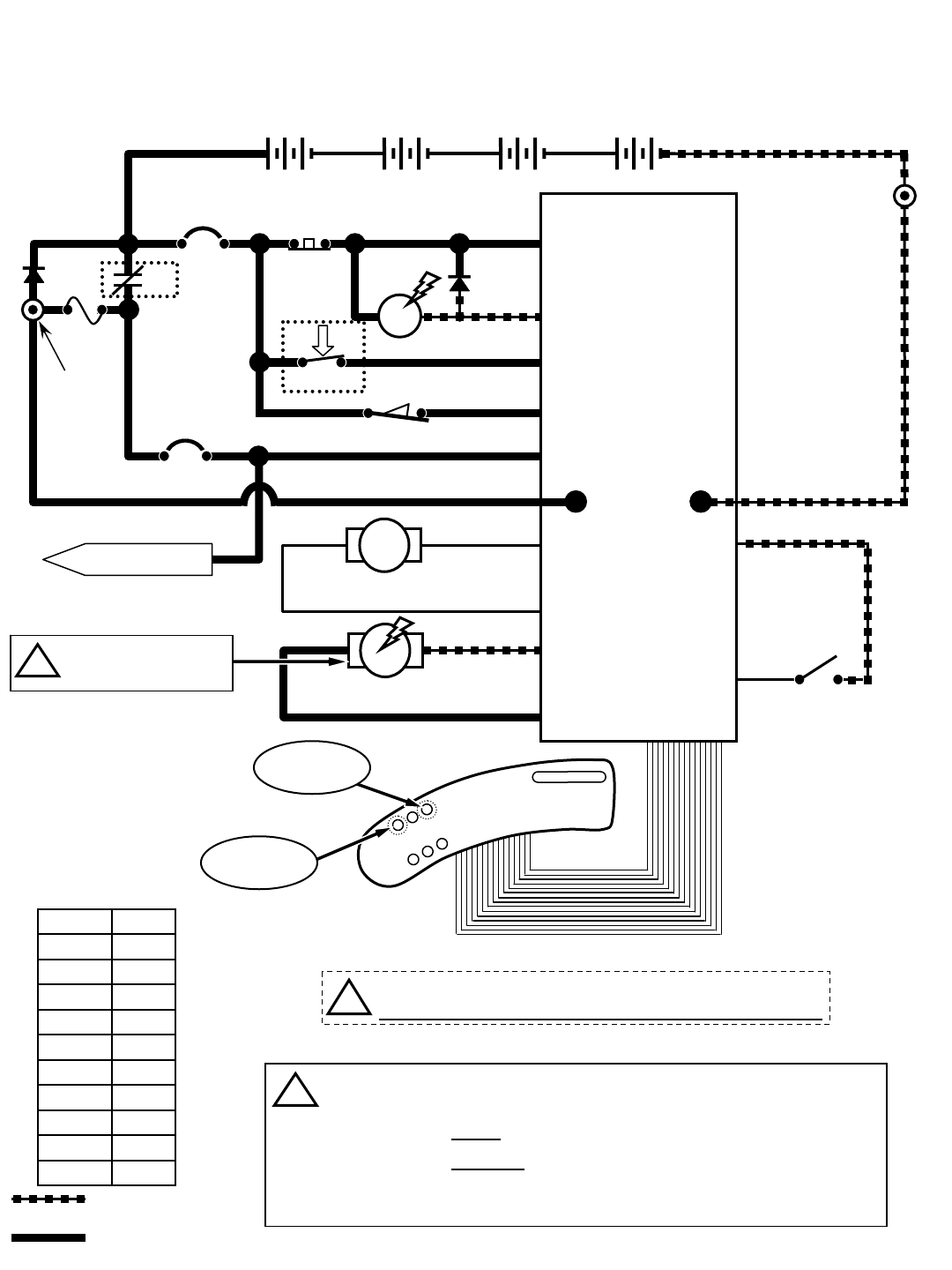
R14 – Brush Motors
Wiring Color Codes
(Unless otherwise marked)
0
1
2
3
4
5
6
7
8
9
Tan
Pink
Brown
Orange
Yellow
Green
Blue
Purple
Gray
White
Right Most Digit
of Wire Number Color of Wire
= Battery Negative
or Logic Ground
= Battery Positive
or Positive Output
CONDITIONS: Key ON, operator on seat, ReadySpace OR Extraction button activated, propel pedal depressed
D2
POS
RIBBON CABLE CONNECTOR P6
CONTROL BOARD
STANDOFF 2
M1B
1 RED
NEG
TOUCH
PANEL
50 RED
S1
M1A
D1
KEYSWITCH
RIBBON CABLE
-
50 RED
214
MAIN CONTACTOR
6
55
56
3
26
3
4
4
44
PIN J6-17
PIN J6-5
PIN J6-24
PIN J6-18
PIN J6-13
14
1 RED
POST J11 POST J7
CB1
5 A
CB2
15 A
+
F1
100 A
SW5
LEFT SIDE
DASH PANEL
13 BLK
7
8
MTR2 PIN J8-1
PIN J8-2
FRONT BRUSH MOTOR
8
1 RED 13 BLK
+-
6 VDC +-
6 VDC +-
6 VDC +-
6 VDC
STANDOFF 1
SW1 CHARGER
INTERLOCK
FLYBACK PATH
9
10
MTR3 PIN J8-3
PIN J8-4
10
TO CB2 PROTECTED
COMPONENTS
14
REAR BRUSH MOTOR
Extraction
Mode Button
ReadySpace
Mode Button
Brush Pressure
Button
Brush Motor Current Draw: Approx. 10 to 20 Amps per motor, varying upon
selected brush pressure setting
Scrub Brush Motors are controlled by PWM (Pulse Width Modulation)
Scrub Brush Motors will function only when propelling either forward or reverse
in ReadySpace mode
Scrub Brush Motors will function only when propelling forward in Extraction mode
Scrub Brush Pressure is controlled by monitoring brush motor current
i
!Be cautious when working near Control Board -
Battery voltage is always present, even with Key OFF
EMERGENCY STOP
SWITCH (E-STOP)
R14 1032129 REV.01 (12-06)
39
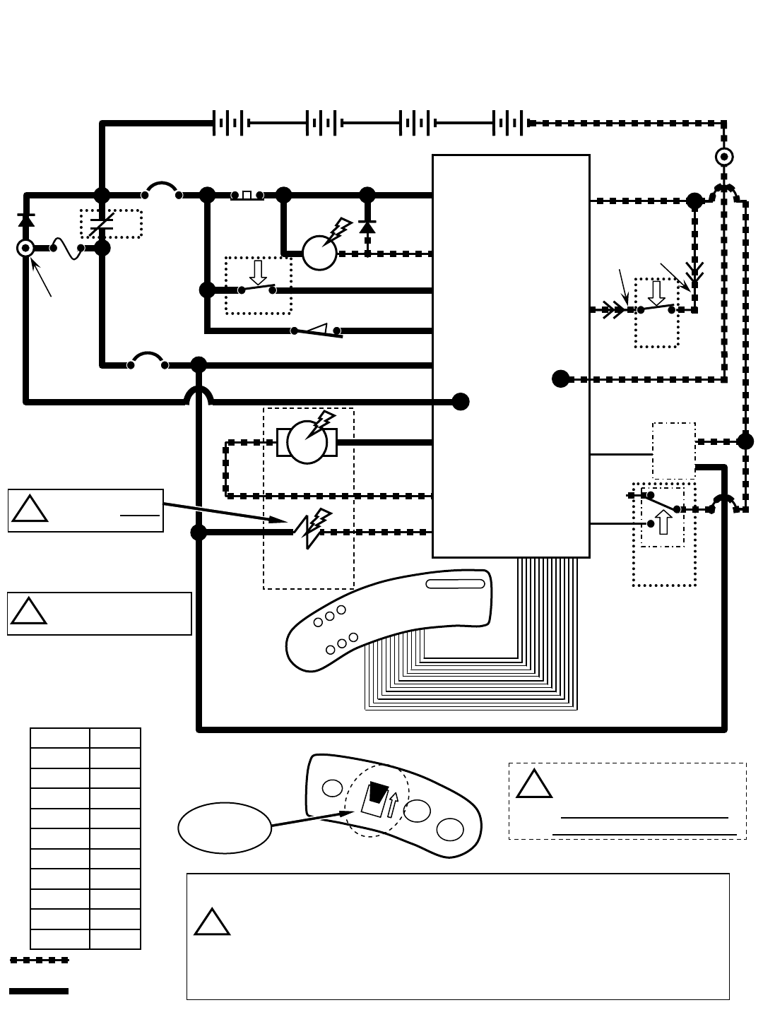
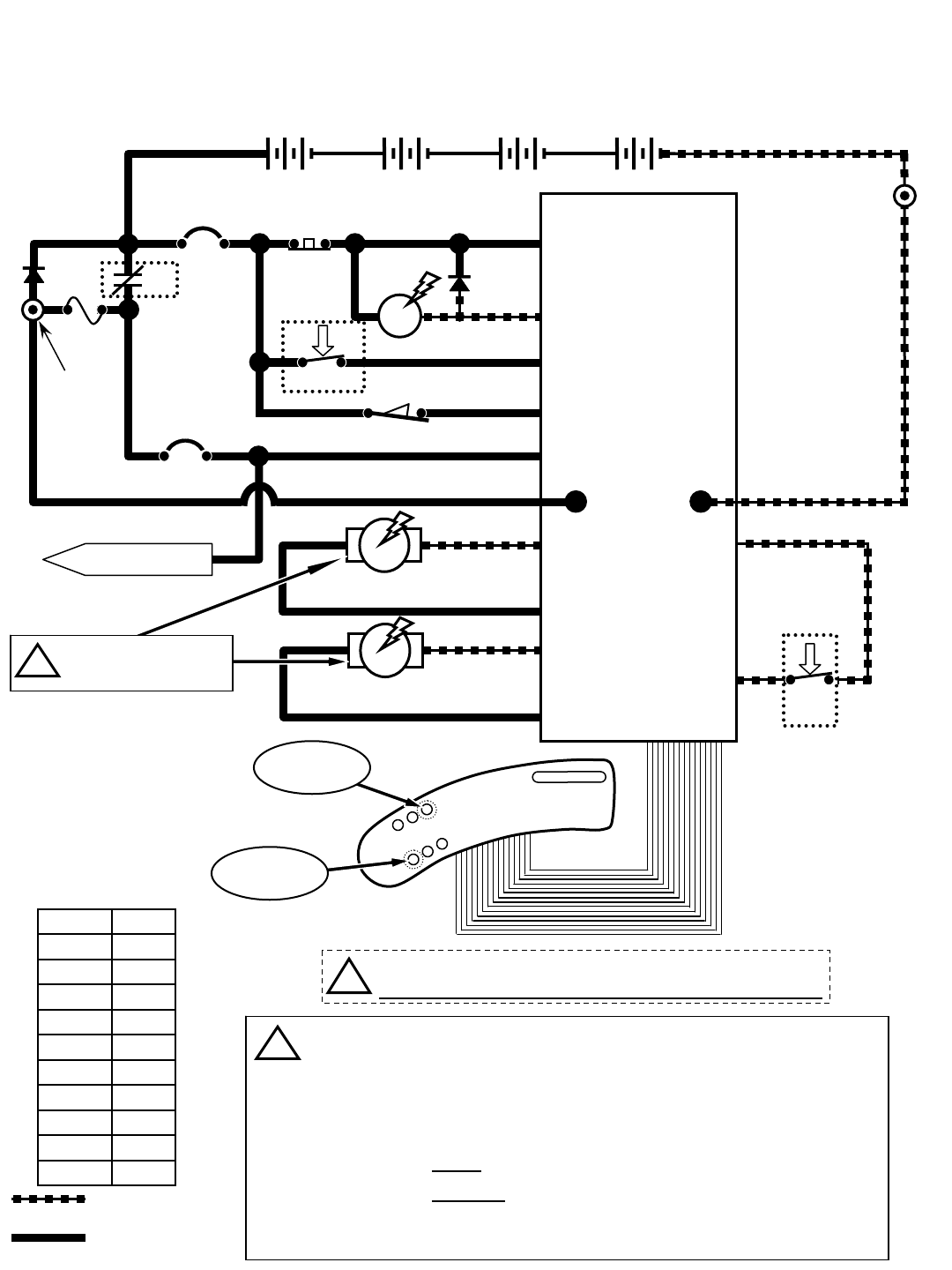
R14 – Vacuum Fan Motors
Wiring Color Codes
(Unless otherwise marked)
0
1
2
3
4
5
6
7
8
9
Tan
Pink
Brown
Orange
Yellow
Green
Blue
Purple
Gray
White
Right Most Digit
of Wire Number Color of Wire
= Battery Negative
or Logic Ground
= Battery Positive
or Positive Output
CONDITIONS: Key ON, ReadySpace OR Extraction OR Wand Switch button activated
D2
POS
RIBBON CABLE CONNECTOR P6
CONTROL BOARD
STANDOFF 2
M1B
1 RED
NEG
TOUCH
PANEL
50 RED
S1
M1A
D1
KEYSWITCH
RIBBON CABLE
-
50 RED
214
MAIN CONTACTOR
6
55
56
3
26
3
4
4
44
PIN J6-17
PIN J6-5
PIN J6-24
PIN J6-18
PIN J6-13
14
1 RED
POST J11 POST J7
CB1
5 A
CB2
15 A
+
F1
100 A
SW5
LEFT SIDE
DASH PANEL
13 BLK
MTR4 PIN J9-1
VACUUM FAN MOTOR 1
1 RED 13 BLK
+-
6 VDC +-
6 VDC +-
6 VDC +-
6 VDC
STANDOFF 1
SW1 CHARGER
INTERLOCK
FLYBACK PATH
MTR9
PIN J9-2
TO CB2 PROTECTED
COMPONENTS
14
Wand Switch
Button
ReadySpace
Mode Button
Extraction
Mode Button
VACUUM FAN MOTOR 2
1212
13 BLK
13 BLK 13 BLK
12
12
Vacuum Fan Motors Current Draw: Approx. 36 to 42 Amps (combined)
Vacuum Fan Motors are controlled by PWM (Pulse Width Modulation)
Pressing the ReadySpace or Extraction button will activate Vacuum Fans
Vacuum Fans can also be operated by pressing the Wand Switch button,
without operating scrub brushes, but propel system will be disabled
i
!Be cautious when working near Control Board -
Battery voltage is always present, even with Key OFF
EMERGENCY STOP
SWITCH (E-STOP)
40
R14 1032129 REV.01 (12-06)
R14 – Solution Pump & Solenoid Valves (ReadySpace Mode)
Wiring Color Codes
(Unless otherwise marked)
0
1
2
3
4
5
6
7
8
9
Tan
Pink
Brown
Orange
Yellow
Green
Blue
Purple
Gray
White
Right Most Digit
of Wire Number Color of Wire
= Battery Negative
or Logic Ground
= Battery Positive
or Positive Output
CONDITIONS: Key ON, ReadySpace button activated, propel pedal depressed
D2
POS
RIBBON CABLE CONNECTOR P6
CONTROL BOARD
STANDOFF 2
M1B
1 RED
NEG
50 RED
S1
M1A
D1
KEYSWITCH
RIBBON CABLE
-
50 RED
214
MAIN CONTACTOR
6
55
56
3
26
3
4
4
44
PIN J6-17
PIN J6-5
PIN J6-24
PIN J6-18
PIN J6-13
14
1 RED
POST J11 POST J7
CB1
5 A
CB2
15 A
+
F1
100 A
SW5
LEFT SIDE
DASH PANEL
13 BLK
PIN J6-25
SOLUTION PUMP
1 RED 13 BLK
+-
6 VDC +-
6 VDC +-
6 VDC +-
6 VDC
STANDOFF 1
SW1 CHARGER
INTERLOCK
FLYBACK PATH
MTR7
PIN J6-6
14
TOUCH
PANEL
ReadySpace
Mode Button
48
PIN J6-4
PIN J6-19
14
14
14
14
F4
7.5A 22
SOL1
SOL2
SOL3
READYSPACE
SOLENOID VALVE
EXTRACTION
SOLENOID VALVE
READYSPACE
FLUSH SOLENOID
VALVE
51
16
46
!Be cautious when working near Control Board -
Battery voltage is always present, even with Key OFF
During ReadySpace operation, the Flush Solenoid Valve (SOL3) will
activate every 2.5 minutes, for a duration of 3 seconds
i
EMERGENCY STOP
SWITCH (E-STOP)
R14 1032129 REV.01 (12-06)
41
R14 – Solution Pump & Solenoid Valves (Extraction Mode)
Wiring Color Codes
(Unless otherwise marked)
0
1
2
3
4
5
6
7
8
9
Tan
Pink
Brown
Orange
Yellow
Green
Blue
Purple
Gray
White
Right Most Digit
of Wire Number Color of Wire
= Battery Negative
or Logic Ground
= Battery Positive
or Positive Output
D2
POS
RIBBON CABLE CONNECTOR P6
CONTROL BOARD
STANDOFF 2
M1B
1 RED
NEG
50 RED
S1
M1A
D1
KEYSWITCH
RIBBON CABLE
-
50 RED
214
MAIN CONTACTOR
6
55
56
3
26
3
4
4
44
PIN J6-17
PIN J6-5
PIN J6-24
PIN J6-18
PIN J6-13
14
1 RED
POST J11 POST J7
CB1
5 A
CB2
15 A
+
F1
100 A
SW5
LEFT SIDE
DASH PANEL
13 BLK
PIN J6-25
SOLUTION PUMP
1 RED 13 BLK
+-
6 VDC +-
6 VDC +-
6 VDC +-
6 VDC
STANDOFF 1
SW1 CHARGER
INTERLOCK
FLYBACK PATH
MTR7
PIN J6-6
14
TOUCH
PANEL
48
PIN J6-4
PIN J6-19
14
14
14
14
F4
7.5A 22
SOL1
SOL2
SOL3
READYSPACE
SOLENOID VALVE
EXTRACTION
SOLENOID VALVE
READYSPACE
FLUSH SOLENOID
VALVE
51
16
46
CONDITIONS: Key ON, Extraction button activated, propel pedal depressed
Extraction
Mode Button
!Be cautious when working near Control Board -
Battery voltage is always present, even with Key OFF
EMERGENCY STOP
SWITCH (E-STOP)
42
R14 1032129 REV.01 (12-06)

R14 – Operational Modes & Interlocks
Mode Entry Sequence Indicator Function
−Directional Switch Forward −Directional Switch in Forward position
−Propel Pedal Depressed
−Directional Switch Reverse −Directional Switch in Reverse position
−Propel Pedal Depressed −Horn Sounding continuously ON & OFF (except in
"Hospital" mode)
ReadySpace
Mode
−Press ReadySpace Button (ON) −ReadySpace LED ON
Activate Soil Transfer Rollers,
Vacuum Fans & Solution Flow
operations
Extraction
Mode
−Press Extraction Button (ON) −Extraction LED ON
Activate Extractor brushes, Vacuum
Shoes, Vacuum Fans & Solution
Flow operations
−ReadySpace or Extraction mode
selected −ReadySpace or Extraction LED ON
−Forward mode enabled −One (1) Propel Speed LED ON
−ReadySpace or Extraction mode
selected −ReadySpace or Extraction LED ON
−Press Propel Speed Button −Two (2) Propel Speed LED's ON
−Forward mode enabled
−Press Extraction Button (ON) −Extraction LED ON
−Press Solution Flow Button (OFF) −Solution Flow LED OFF
−ReadySpace or Extraction mode
selected −ReadySpace or Extraction LED ON
−Propel Pedal Depressed −One (1) Brush Pressure LED ON
−ReadySpace or Extraction mode
selected −ReadySpace or Extraction LED ON
−Propel Pedal Depressed −Two (2) Brush Pressure LED's ON
−Press Brush Pressure Button
Recovery Tank
Full
−Recovery Tank Full (Float Switch
Closed) −Recovery Tank Full LED ON Disables Cleaning function one
minute after indicator is lit
Battery
Discharged
−Battery voltage at or below full
discharge voltage −Red LED (on Battery Gauge) blinking Disables Cleaning function
−Fault LED ON and:
Solution LED Blinking (Front Brush Motor) and/or
Propel Speed (+) LED Blinking (Rear Brush Motor)
Normal Down
Pressure Mode
Limits maximum scrub head down
pressure during cleaning
Heavy Down
Pressure Mode
Allows heavier than Normal scrub
head down pressure during cleaning
Prevent damage to Scrub Brush
Motors – Cleaning function shuts
OFF
Brush Motor
Over Current
Fault
−Controller sensed an Over
Current condition in a Brush
Motor(s)
−Solution Tank Empty LED ON Disables Cleaning function one
minute after indicator is lit
Solution Tank
Empty
−Solution Tank Empty (Float Switch
Open)
Forward
Reverse
Solution OFF
Mode
(Extraction
Mode ONLY)
Wand Mode
(Optional feature)
Cleaning Speed
- Standard
(Recommended
cleaning speed)
Cleaning Speed
- Fast
Collect solution on floor with Off-
Aisle Wand attachment (Propel is
disabled while in Wand Mode)
−Press Wand Button (ON) −Wand LED ON
Forward movement of machine
Reverse movement of machine
Disable solution spray in Extraction
Mode
Limits maximum forward propel
speed during cleaning
Allows faster than Standard forward
propel speed during cleaning
R14 1032129 REV.01 (12-06)
43

R14 – Diagnostic & Fault Alarms
High Current Faults
(Refer to page 46 for LED locations)
Alarm Codes
Fault Entr
y
Se
q
uence Indicato
r
Excessive Front Brush
Motor Current
Front brush motor current higher than 29 Amps Blinking FAULT LED,
Blinking Solution LED
Excessive Rear Brush
Motor Current
Rear brush motor current higher than 29 Amps Blinking FAULT LED,
Blinking Speed (+) LED
Excessive Vacuum Fan
Motors Current
Vacuum Fan Motors (combined)
current higher than 60 Amps
Blinking FAULT LED,
Blinking Extraction LED
Excessive Scrub Head
Actuator Motor Current
Scrub head actuator current 8 Amps or higher Blinking FAULT LED,
Blinking Brush Pressure (+) LED
Excessive Extraction Shoes
Actuator Motor Current
Extraction Shoes actuator
current 8 Amps or higher
Blinking FAULT LED,
Blinking Brush Pressure (-) LED
Excessive Propel
Motor Current
Blinking FAULT LED for 10 seconds,
then Propel disabled
68 to 70 Amps for 4 min. OR
higher than 70 Amps for 15 seconds
Mode Entry Sequence Alarm Sequence Function
Back-Up Alarm
Directional switch
placed in REVERSE Horn sounds
1
beep cycle (repeats)
Alerts nearby persons of machine
backward movement (Note: Back-up
alarm will not sound when machine is
placed in "Hospital" mode)
Propel Interlock:
Seat Switch Released
Propel Pedal depressed
with operator NOT on
seat Horn sounds
2
beep cycle (repeats) Prevents movement of machine when
operator is not on seat
Propel interlock:
High Pedal Disable
Key switch turned ON
with Propel
Pedal engaged Horn sounds
4
beep cycle (repeats)
Prevents movement of machine when
key switched ON while throttle
depressed
Propel Interlock:
Throttle Fault
Controller sensed
an out-of range
Throttle signal
Horn sounds
5
beep cycle (repeats)
(Also FAULT LED blinks)
Prevents movement of machine with
invalid throttle voltage. Cleaning
function shuts off.
Propel Interlock:
Parking Brake Fault
Controller sensed an out-
of range
Brake signal
Horn sounds
6
beep cycle (repeats)
(Also FAULT LED blinks)
Prevents movement of machine with
invalid brake voltage. Cleaning function
shuts off.
Propel Interlock:
Parking Brake Unplugged
Controller sensed open
circuit on parking brake Horn sounds
7
beep cycle (repeats)
(Also FAULT LED blinks)
Prevents movement of machine with
ineffective parking brake. Cleaning
function shuts off.
Propel Interlock:
Emergency Stop Switch
Activated
Controller sensed open
circuit on Emergency
Stop Switch circuit Horn sounds
8
beep cycle (repeats)
Disables all functions (Note: To reset,
key switch must be cycled OFF and
ON after the Emergency Stop switch
has been reset)
Propel Interlock:
Charger Plugged In
Battery charger plugged
into machine with
Key Switch ON Horn sounds
9
beep cycle (repeats) Prevents movement of the machine
with charger plugged in
44
R14 1032129 REV.01 (12-06)

R14 – Diagnostic & Configuration Modes
Mode Entry Sequence Indicator Function
Upper Speed (+) LED blinks Tens of day of
month, Upper Brush Pressure (+) LED blinks
Single day of month
Lower Speed (-) LED blinks Tens of month,
Lower Brush Pressure (-) LED blinks Single
month
Solution Flow LED blinks Tens of year, Wand
Tool LED blinks out Single year
Self Test Mode
(Refer to page 48 for detailed
instructions for this mode)
Press and hold the
ReadySpace and Extraction
Buttons, turn key switch ON,
release buttons after the relay
clicks
Start of test - Front Brush motor turns ON
End of test - Horn sounds
All Battery LED's flashing indicate OK, A
Flashing LED (other than Battery LED's)
indicates an OPEN Fault, A Solid lit LED
indicates a SHORT Fault
Input Display Mode
(Refer to page 49 for detailed
instructions for this mode)
Press and hold Wand Tool
Button, turn key switch ON,
release button after forth
battery LED starts to blink
#4 battery LED blinks Shows state of control board inputs from
various switches and sensors
Manual Mode
(Refer to page 50 for detailed
instructions for this mode)
Press and hold Solution Flow
Button, turn key switch ON,
release after third Battery LED
starts to blink.
#3 Battery LED blinks
Allows operation of individual functions
without the safety interlocks affecting or
controlling them
Propel/Brake Diagnostic
Mode
(Refer to page 51 for detailed
instructions for this mode)
Press and hold ReadySpace
and Speed Buttons, turn key
switch ON, release after battery
LED's are OFF
ReadySpace LED ON if in Forward OR
Extraction LED ON if in Reverse - Brush
Pressure and Wand Tool LED's display
position of Propel Pedal, Speed and Solution
Flow LED's display position of Brake Pedal,
Battery LED's display Propel Motor current
level
Provides information regarding brake
pedal signal, propel pedal signal, and
propel motor current
Reverse Alarm
Select Mode
(Refer to page 53 for detailed
instructions for this mode)
Put directional switch in
Reverse, press & hold Horn
Button, turn key switch ON
Horn sounds or is silent Allows enable/disable of
Backup alarm (Hospital Mode)
Display Software
Revision Mode
(Refer to page 47 for detailed
instructions for this mode)
Press and hold ReadySpace
Button, turn key switch ON,
wait 10 seconds, release
ReadySpace Button
Blinking LED’s indicate software revision
date
R14 1032129 REV.01 (12-06)
45
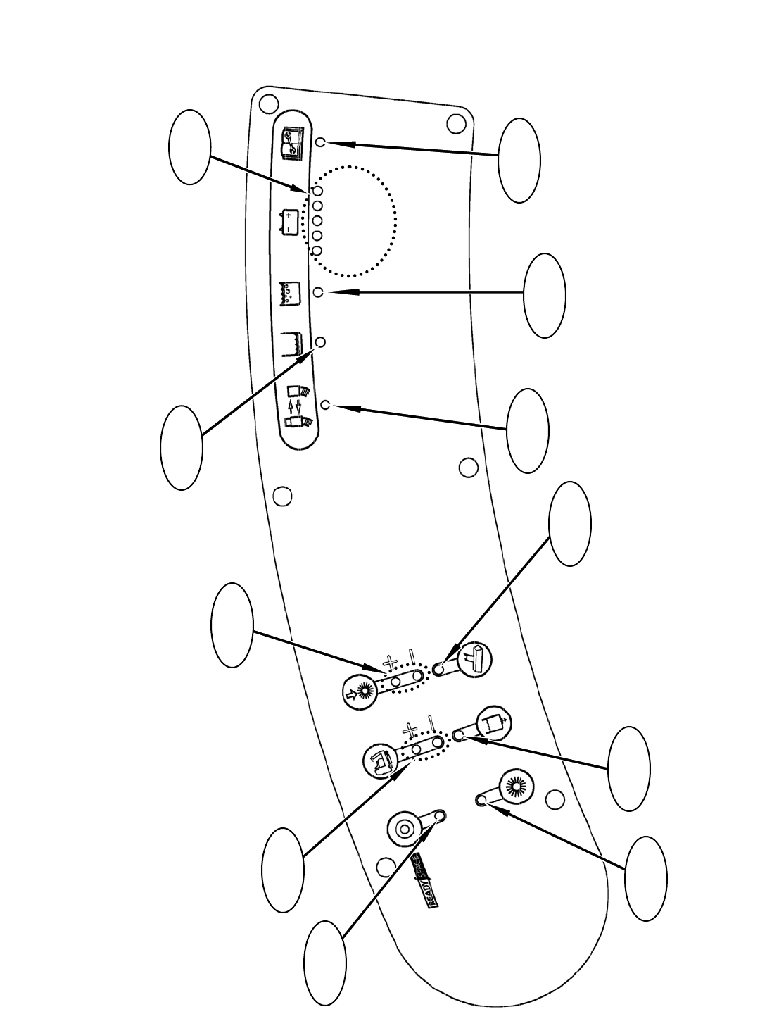
R14 – LED Locations & Descriptions
3
GREEN
GREEN
GREEN
451 2
RED
YELLOW
Fault Indicator
LED
Solution Tank
Empty LED
Recovery Tank
Full LED
Battery
LED’s
Hose Fault
LED
Wand Tool
LED
Solution Flow
LED
Extraction
Mode LED
Brush Pressure
LED’s
Propel Speed
LED’s
ReadySpace
Mode LED
46
R14 1032129 REV.01 (12-06)
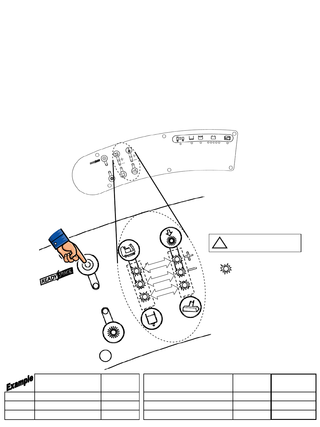
R14 – Display Software Revision Mode
TO ENTER: • Press and hold ReadySpace Button
• Turn key switch ON, wait 10 seconds
• Release Button
READING THE SOFTWARE REVISION:
• Upper Speed (+) LED blinks Tens of DAY of month,
Upper Brush Pressure (+) LED blinks Single DAY of month
• Lower Speed (-) LED blinks Tens of MONTH,
Lower Brush Pressure (-) LED blinks Single MONTH
• Solution Flow LED blinks Tens of YEAR,
Wand Tool LED blinks out Single YEAR
= BLINKING (except if zero)
TOUCH
PANEL LEFT SIDE
DASH PANEL
TENS ONES
DAY
MONTH
YEAR
An LED that does NOT
blink is the digit ZERO (0)
i
TENS
LED's # of
Blinks ONES
LED's # of
Blinks
Revision
Date
Day Upper Speed (+) LED 2Upper Brush Pressure (+) LED 9 29th
Month Lower Speed (-) LED 0 (LED OFF) Lower Brush Pressure (-) LED 9 September
Year Solution LED 0 (LED OFF) Wand LED 6 2006
Push & Hold,
Turn Key Switch On
R14 1032129 REV.01 (12-06)
47
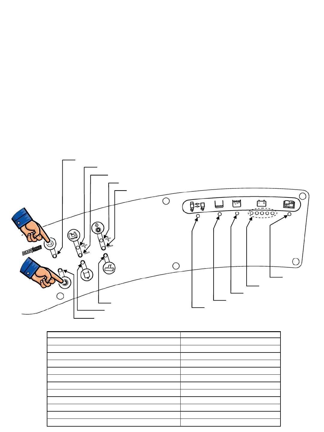
R14 – Self Test Mode
TO ENTER: • Press and hold ReadySpace & Extraction Buttons
• Turn key switch ON
• Release Buttons after the relay clicks
• The entire Self Test takes approximately 40 seconds
• At the Start of the Self Test, the Front Brush motor turns ON
• At the End of the Self Test, the Horn sounds
AFTER THE SELF TEST IS COMPLETE:
• If the Battery LED’s are blinking, NO FAULTS were found
• If any LED is blinking (other than Battery LED’s), an OPEN FAULT
was found (refer to diagram below)
• If any LED is lit solid, a SHORT FAULT was found refer to table
below (refer to diagram below)
ReadySpace Solenoid Valve Fault
Scrub Head Actuator Fault
Extraction Shoes Actuator Fault
Front Brush Motor Fault
Rear Brush Motor Fault
Vacuum Fan Motor Fault
Solution Pump Fault
Brake Solenoid Fault
Extraction Solenoid Valve Fault
ReadySpace Flush Solenoid Valve Fault
Horn Fault
All Systems OK
LED (Flashing = OPEN, Solid = SHORT) System at Fault
Battery LED's Flashing No Faults Found
ReadySpace LED ReadySpace Solenoid Valve
Extraction LED Extraction Solenoid Valve
Upper Speed (+) LED Scrub Head Actuator
Lower Speed (-) LED Extraction Shoes Actuator
Solution LED Solution Pump
Upper Brush Pressure (+) LED Front Brush Motor
Lower Brush Pressure (-) LED Rear Brush Motor
Wand LED Vacuum Fan Motor
Hose LED ReadySpace Flush Solenoid Valve
Solution Tank Empty LED Brake Solenoid
Recovery Tank Full LED Horn/Back-up Alarm
Push & Hold,
Turn Key Switch On
Push & Hold,
Turn Key Switch On
Fault Indicator
48
R14 1032129 REV.01 (12-06)
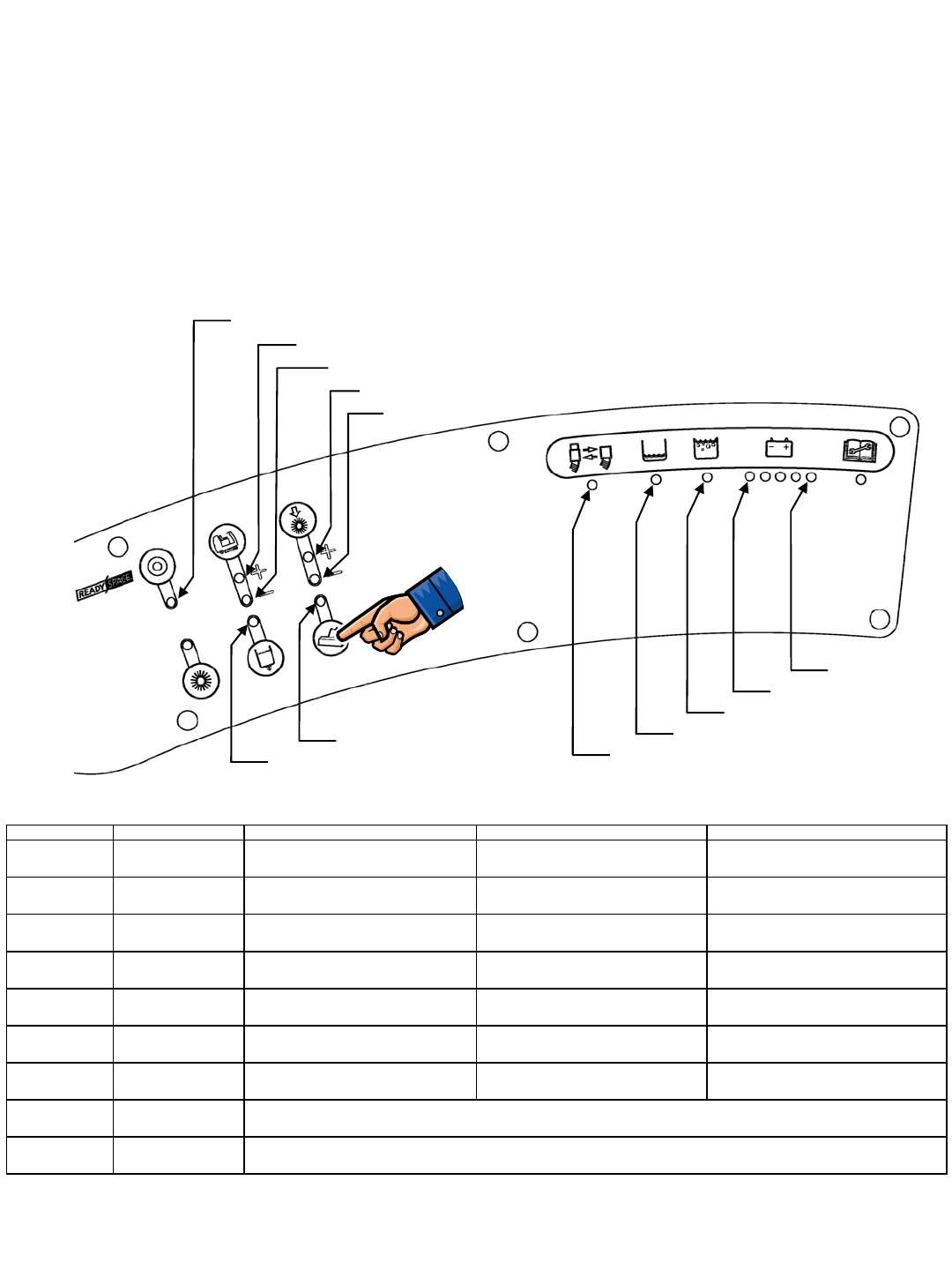
R14 – Input Display Mode
TO ENTER: • Press and hold the Wand Button
• Turn key switch ON
• Release Button after the # 4 Battery LED blinks
The purpose of the Input Display Mode is to show the condition of various control board inputs
NOTE: For Propel & Brake signal troubleshooting, refer to the Propel Diagnostics Mode page
Charger Interlock Switch
Hose Switch
Front Brush ON
Front Brush Heavy Pressure
Solution Tank Float Switch
Seat Switch
Low Battery Voltage
Rear Brush Heavy Pressure
Rear Brush ON
Front Brush Standard Pressure
Rear Brush Standard Pressure
Recovery Tank Float Switch
INPUT ASSOCIATED LED(s) LED IS ON WHEN: LED IS OFF WHEN: NOTES
Charger Interlock
Switch ReadySpace LED Battery charger IS NOT plugged in
(switch is CLOSED) Battery charger IS plugged in
(switch is OPEN) ReadySpace system will still operate, but
without indicator
Seat Switch # 5 (Green)
Battery LED Operator IS NOT sitting on seat (switch
is OPEN) Operator IS sitting on Seat
(switch is CLOSED)
Recovery Tank
Float Switch Recovery Tank
Full LED Recovery tank IS FULL (switch must be
CLOSED for 5 to 7 seconds) Recovery tank IS NOT FULL
(switch is OPEN)
Solution Tank
Float Switch Solution Tank
Empty LED Solution tank IS EMPTY (switch must be
OPEN for 5 to 7 seconds) Solution tank IS NOT EMPTY
(switch is CLOSED)
Emergency Stop
Switch none N/A N/A Horn will repeat 8 beep cycle when
Emergency Stop Switch is activated
Battery Voltage # 1 (Red)
Battery LED Battery needs charging
(LED is BLINKING) Battery has sufficient charge level
Hose Switch Hose switch LED ReadySpace hose is NOT connected
(switch is OPEN) ReadySpace hose IS connected
(switch is CLOSED)
Front Brush
Pressure Speed & Solution
LED's
Rear Brush
Pressure Brush Pressure &
Wand LED's
Lower Propel Speed (-) LED is ON when Front Brush is running; Upper Propel Speed (+) LED is ON when Heavy Brush
pressure is selected; Solution LED is ON when Standard Brush Pressure is selected
Lower Brush Pressure (-) LED is ON when Rear Brush is running; Upper Brush Pressure (+) LED is ON when Heavy Brush
pressure is selected; Wand LED is ON when Standard Brush Pressure is selected
Push & Hold,
Turn Key Switch On
R14 1032129 REV.01 (12-06)
49
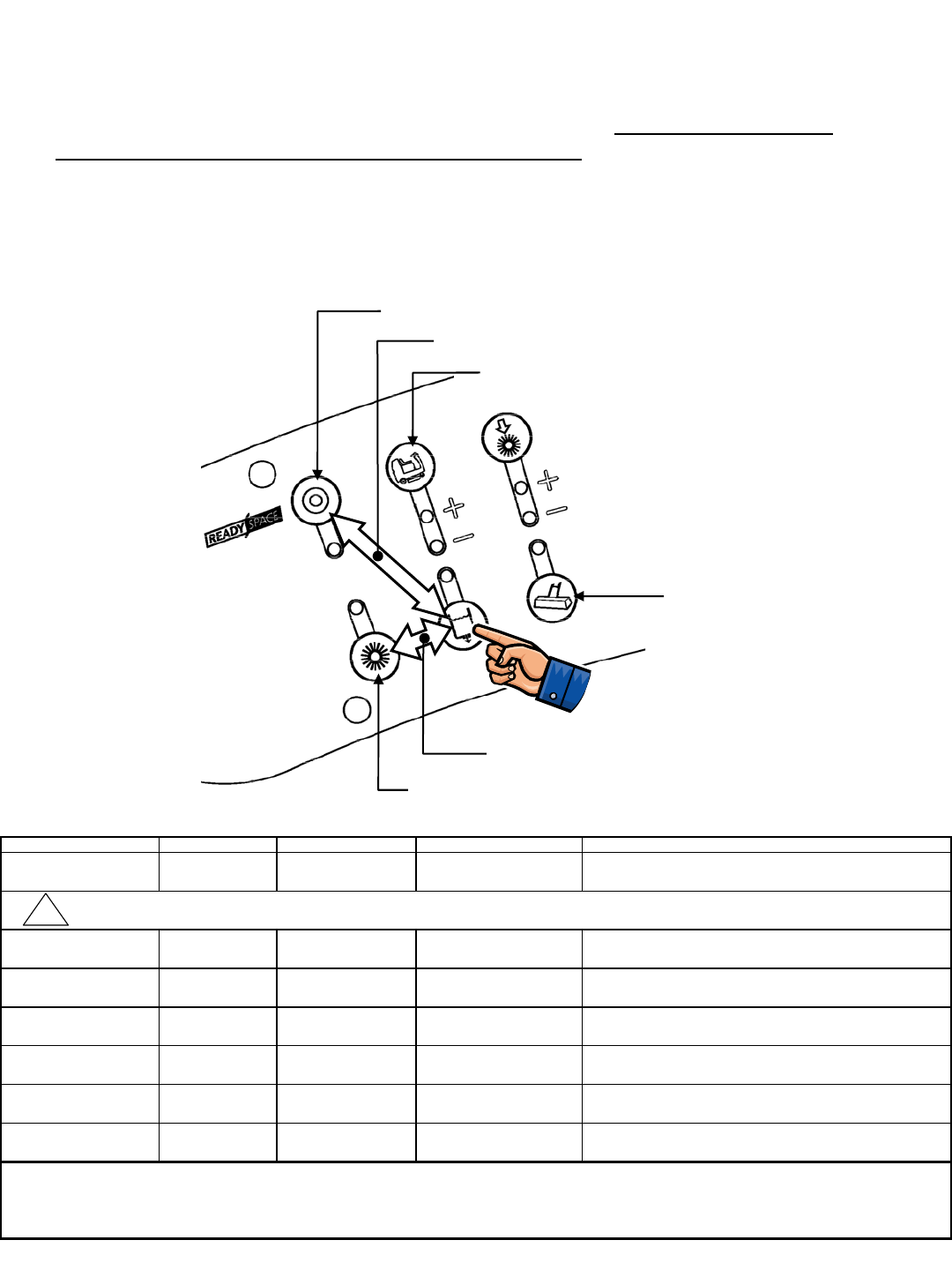
R14 – Manual Mode
TO ENTER: • Press and hold the Solution Button
• Turn key switch ON
• Release Button after # 3 Battery LED blinks
The purpose of the Manual Mode is to allow the technician to exercise individual cleaning
functions on the machine. In Manual Mode, most of the Normal mode interlocks are
disabled. All Propel functions are disabled in Manual Mode. Extreme care must be
exercised when operating the machine in this mode.
Lower Scrub Head & Turn Brushes ON
Raise Scrub Head & Turn Brushes OFF
Toggle Vacuum Fan ON/OFF
PUSH
BOTH
PUSH
BOTH
Toggle Extraction Solution Spray ON/OFF
Toggle Extractor Shoes UP/DOWN
Toggle ReadySpace Solution Spray ON/OFF
FUNCTION BUTTON(S) ACTION INDICATOR NOTES
Lower Scrub Head ReadySpace Press & Hold Scrub head will continue to
lower as long as button is held
Scrub Brushes
lR
R
Turn OFF Scrub Brushes
and Raise Scrub Head Extraction Press & Hold
o
Raise/Lower Extractor
Shoes Propel Speed Press & Release Extractor Shoes can be toggled
UP & DOWN by pressing the Propel Speed button
Vacuum Fan Wand Press & Release Wand LED Vacuum Fan can be toggled
ON & OFF by pressing the Wand button
ReadySpace
Solution Spray
Solution &
ReadySpace Press & Release Solution &
ReadySpace LED's
Solution Pump & ReadySpace valves can be toggled
ON & OFF by pressing the Solution & ReadySpace buttons
Extraction
Solution Spray
Solution &
Extraction Press & Release Solution &
Extraction LED's
Solution Pump & Extraction valves can be toggled
ON & OFF by pressing the Solution & Extraction buttons
• When the Solution Tank Empty switch is OPEN (tank empty), the Solution Tank Empty LED will light
• For safety considerations, the Propel functions are disabled
ADDITIONAL NOTES
• When the Recovery Tank Full switch is CLOSED (tank full), the Recovery Tank Full LED will light
!
CAUTION : Do not hold ReadySpace Button down too long - actuator stall will occur, possibly damaging actuator or control board
Push & Hold,
Turn Key Switch On
50
R14 1032129 REV.01 (12-06)
Turn Brushes ON/OFF
Brush
Pressure
Press &
Release
Scrub head will continue to raise as
long as button is held
On/Off
Scrub brushes can be turned On & Off
by pressing the Brush Pressure button
Scrub head
lowers
Scrub brushes
turn ON or OFF
Scrub head
raises
Extractor shoes
raise or lower
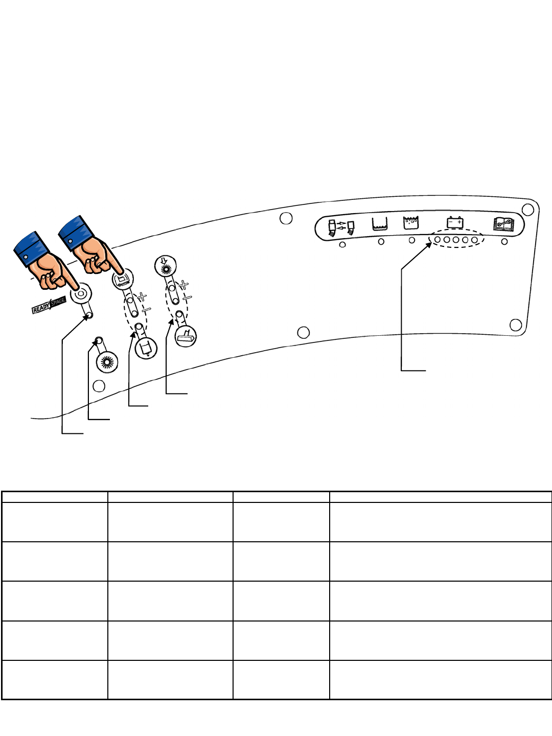
R14 – Propel/Brake Diagnostics
TO ENTER:
• Press and hold ReadySpace & Propel Speed Buttons
• Turn key switch ON
• Release Buttons after ReadySpace LED (if in Forward) or Extraction LED (if in Reverse) is lit
TEST ACTION INDICATOR NOTES
Directional Switch -
Forward Place Directional Switch in
Forward Propel position ReadySpace
LED ON
LED will be illuminated if the controller senses the
Directional Switch in Forward Position - Machine will not
propel if any of the Brake LED’s are illuminated
Directional Switch -
Reverse Place Directional Switch in
Reverse Propel position Extraction
LED ON
LED will be illuminated if the controller senses the
Directional Switch in Reverse Position - Machine will not
propel if any of the Brake LED’s are illuminated
Brake Pedal Depress Brake Pedal Propel Speed &
Solution LED's
LED’s will display the sensed position of the brake
pedal - No LED’s indicate pedal is released, 3 LED’s
indicate that the pedal is fully depressed
Accelerator Pedal Depress Accelerator Pedal Brush Pressure &
Wand LED's
LED’s will display the sensed position of the accelerator
pedal - No LED’s indicate the pedal is released, 3 LED’s
indicate that the pedal is fully depressed
Propel Motor Current Depress Accelerator Pedal Battery LED's
Battery gauge LED’s display the current level being drawn
by the Propel Motor - Each LED represents
7 Amps of current (ex: 3 LED's = 21 Amps)
Forward Indicator
Brake Pedal Position
Reverse Indicator
Accelerator Pedal Position
Propel Motor Current
(Page 1 of 2)
Push & Hold,
Turn Key Switch On
R14 1032129 REV.01 (12-06)
51
R14 – Propel/Brake Diagnostics
Propelling System Data
Propel & Brake Pedal Data
Pedal LED group Lit LED's Pedal Position Input Voltage Level Notes
0 Released below 1.3 VDC
1 Slightly Depressed 1.3 to 1.89 VDC
2 Halfway Depressed 1.89 to 2.27 VDC
3 Fully Depressed 2.27 to 4.0 VDC
0 Released below 1.5 VDC
1 Slightly Depressed 1.5 to 1.89 VDC
2 Halfway Depressed 1.89 to 2.27 VDC
3 Fully Depressed 2.27 to 4.0 VDC
Propel Machine must be in Propel
Diagnostic Mode when testing;
LED's will display the sensed
position of the pedal; No LED's
indicate pedal is released; 3
LED's indicate pedal is fully
depressed
Brake
Brush
Pressure &
Wand LED's
Propel Speed
& Solution
LED's
(Page 2 of 2)
Mode Direction Wire # Color Polarity
25 Green −
24 Yellow "+"
25 Green "+"
24 Yellow −
25 Green −
24 Yellow "+"
25 Green −
24 Yellow "+"
Notes
Forward
Reverse
Voltage during FORWARD travel will vary
from 0 to 24 VDC
Voltage during REVERSE travel will vary
from 0 to approximately 17 VDC
Extraction,
High Speed,
Heavy Down
Pressure
Forward Voltage during FORWARD travel will vary
from 0 to 6 VDC, with a maximum of 20
Amps
Releasing the Propel
Pedal will initiate
Dynamic Braking; As
machine slows to a
halt, the Brake
solenoid is De-
energized, applying the
Parking Brake
Transport
ReadySpace,
High Speed,
Heavy Down
Pressure
Forward Voltage during FORWARD travel will vary
from 0 to 12 VDC, with a maximum of 11
Amps
NOTE: Output to propel motor is PWM (Pulse Width Modulated)
52
R14 1032129 REV.01 (12-06)
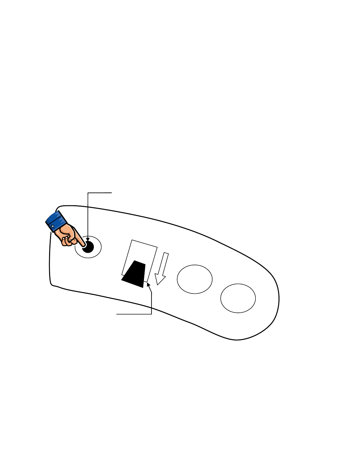
R14 – Reverse Alarm Select Mode
TO ENTER: • Put directional switch in Reverse
• Press & Hold Horn Button
• Turn key switch ON
• If Back-up Alarm is silent, Hospital (Quiet) Mode has been selected
• If Back-up Alarm is sounding, Normal Mode has been selected
• Cycle key switch OFF, then ON again
• Verify correct mode has been chosen
Reverse Alarm Select Mode allows enabling or disabling of the Backup Alarm
FORWARD
REVERSE
Horn Switch
Directional Switch
RIGHT SIDE
DASH PANEL
Push & Hold,
Turn Key Switch On
R14 1032129 REV.01 (12-06)
53

Main Contactor EE
X
E
X
Propel Forward EE
X
E
X
E
X
E
X
E(1)
X
NOTE
(4)
X
Propel Reverse EE
XX
EE
X
E
X
E(1)
X
NOTE
(3) NOTE
(3)
X
Dynamic Braking
Force - Increase EE E E E
Parking Brake
Engage
X
EEE
X
E(2) E
Scrub Head Lower EE
X
E
X
E
X
E
X
E
X
EEE
X
Scrub Motors EE
X
E
X
E
X
E
X
E
X
E
X
E
X
EEE NOTE
(5)
X
Vacuum Motors EE
X
E
X
E
X
E
X
E
X
EEE E
Solution Pump EE
X
E
X
E
X
E
X
EE
X
EEE E
Extraction
Shoes Lower EE
X
E
X
E
X
E
X
E
X
E
XX
EE
X
Extraction
Solenoid Valve EE
X
E
X
E
X
E
X
E
X
E
X
E
XX
E
XX
ReadySpace
Solenoid Valve EE
X
E
X
E
X
E
X
E
X
E
X
E
X
E
XX X
ReadySpace Flush
Solenoid Valve E
X
E
X
E
X
E
X
E
X
E
X
E
XX X
Hour Meter
(NOTE 6) EEEE
X
E
X
EEEEE
Horn EE
Battery
Gauge Reset E
E
= In
p
ut that will ENABLE Out
p
ut
X = Input that will DISABLE Output
NOTE (1) = Propel functions disabled if both brake and throttle pedals are pressed
NOTE (2) = After timer expires
NOTE (3) = Reverse propel raises the extractor shoes
NOTE (4) = Allows faster propel speed during cleaning functions
NOTE (5) = Allows heavier scrub pressure during cleaning functions
NOTE (6) = Hour Meter is activated anytime Vacuum Fan Motors are ON
A
ND/OR machine is in motion (propelling)
Wand Tool Switch ON
Seat Switch
(Operator OFF seat)
Propel Switch
REVERSE
Emergency Stop
Switch NOT Pressed
Emergency Stop
Switch Pressed
Charger Switch
(Chgr NOT connected)
Recovery Tank Float
Switch (Tank FULL)
Solution Tank Float Switch
(Tank NOT EMPTY)
Solution Tank Float Switch
(Tank EMPTY)
Hose Switch (WRONG
hose attached for mode)
Extraction Mode ON /
Solution ON
Outputs
Charger Switch
(Charger connected)
Recovery Tank Float
Switch (Tank NOT FULL)
Seat Switch
(Operator ON seat)
Inputs and the
Outputs they
Control
Key Switch ON
Extraction Mode ON /
Solution OFF
Throttle Input
(Pedal depressed)
In
p
uts
Propel Switch
FORWARD
Brake Input
(Pedal depressed)
Horn Switch
(Button depressed)
Hose Switch (CORRECT
hose attached for mode)
Heavy Scrub Head
Pressure (+)
High Propel Speed (+)
ReadySpace Mode ON
R14 – Inputs & Outputs Table
54
R14 1032129 REV.01 (12-06)
