S30 Service Manual Tennant Rider Floor Sweeper
2018-06-12
: Sweepscrub Tennant-S30-Rider-Floor-Sweeper-Service-Manual tennant-s30-rider-floor-sweeper-service-manual 2748 file product_file
Open the PDF directly: View PDF ![]() .
.
Page Count: 136 [warning: Documents this large are best viewed by clicking the View PDF Link!]
- S30 Service Information Manual
- SAFETY PRECAUTIONS
- GENERAL MACHINE INFORMATION
- MAINTENANCE & REPAIR
- MAINTENANCE CHECKPOINTS
- MAINTENANCE CHART (1 of 2)
- LUBRICATION
- HYDRAULICS
- ENGINE
- BATTERY
- FUSES AND RELAYS
- REMOVING AND INSPECTING THE DUST FILTER
- CLEANING THE DUST FILTER
- MAIN BRUSH
- SIDE BRUSH
- SKIRTS AND FLAPS
- SEALS
- BRAKES AND TIRES
- PROPELLING MOTOR
- PUSHING, TOWING, AND TRANSPORTING THE MACHINE
- MACHINE JACKING
- STORAGE INFORMATION
- ELECTRICAL
- Electrical Symbols & Abbreviations
- Fuses and Relays (S30,S30XP,S30X4) (1 of 2)
- S30 Electrical Schematic (1 of 4)
- S30XP / S30X4 Electrical Schematic (1 of 4)
- Gasoline Engine Harness Electrical Schematic (1 of 2)
- LPG Engine Harness Electrical Schematic (1 of 2)
- Diesel Engine Harness Electrical Schematic
- Cab Harness Electrical Schematic
- S30 Wire Harness Drawing (1 of 2)
- S30XP / S30X4 Wire Harness Drawing (1 of 3)
- Hopper Cover Wire Harness Drawing
- Hopper Wire Harness Drawing
- Diesel Engine Wire Harness Drawing
- Cab Wire Harness Drawing
- Key Switch Information
- Key OFF Power Distribution (S30)
- Key OFF Power Distribution (S30XP,S30X4)
- Key ON Power Distribution (S30)
- Key ON Power Distribution (S30XP,S30X4)
- Main & Side Brushes ON (S30)
- Main & Side Brushes ON (S30XP,S30X4)
- Vacuum Fan ON (S30)
- Vacuum Fan ON (S30XP,S30X4)
- Filter Shaker ON (S30)
- Filter Shaker ON (S30XP,S30X4)
- Hopper Lift (S30)
- Hopper Lift (S30XP,S30X4)
- Hopper Lower (S30)
- Hopper Lower (S30XP,S30X4)
- Hopper Door Open -- Automatic (S30)
- Hopper Door Open -- Manual (S30)
- Hopper Door Open (S30XP,S30X4)
- Hopper Door Close -- Automatic (S30)
- Hopper Door Close (S30XP,S30X4)
- Display Module Fault Indicators (S30)
- Fault Indicators (S30XP,S30X4)
- Dash Fault Indicators (S30,S30XP,S30X4)
- Operating, Maintenance, & Diagnostic Modes (S30XP,S30X4) (1 of 2)
- HYDRAULIC
- General Information
- Hydraulic Schematic (S30, S30XP) (1 of 2)
- Hydraulic Schematic (S30X4) (1 of 2)
- Overall Hydraulic Hose Diagram (S30)
- Overall Hydraulic Hose Diagram (S30XP)
- Overall Hydraulic Hose Diagram (S30X4)
- Hydraulic Reservoir Hose Diagram
- Hydraulic Cooler Hose & Tube Diagram
- Hydraulic Pumps Diagram (S30, S30XP)
- Hydraulic Pumps Diagram (S30X4)
- Hydraulic Valve Block Diagram (S30)
- Hydraulic Valve Block Diagram (S30XP, S30X4)
- Hydraulic Priority and Flow Divider Valve Diagram (S30X4)
- Left Hand Side Brush Hydraulic Diagram (S30XP, S30X4)
- Main Brush ON
- Main Brush & Side Brush(es) ON
- Hopper Door Open
- Hopper Door Close
- Hopper Lift
- Hopper Lower
- Vacuum Fan ON
- Main Brush Lower (S30XP, S30X4)
- Main Brush & Side Brush(es) Lower (S30XP, S30X4)
- 3--Wheel Steering System (S30, S30XP)
- 4--Wheel Steering System (S30X4)
- 3--Wheel Propel System (S30, S30XP)
- 4--Wheel Propel System (S30X4)
S30
*9004086*
www.tennantco.com
9004086
Rev. 00 (04-2008)
North America / International
Sweeper
Service Information Manual
Home
Find...
Go To..
A
B
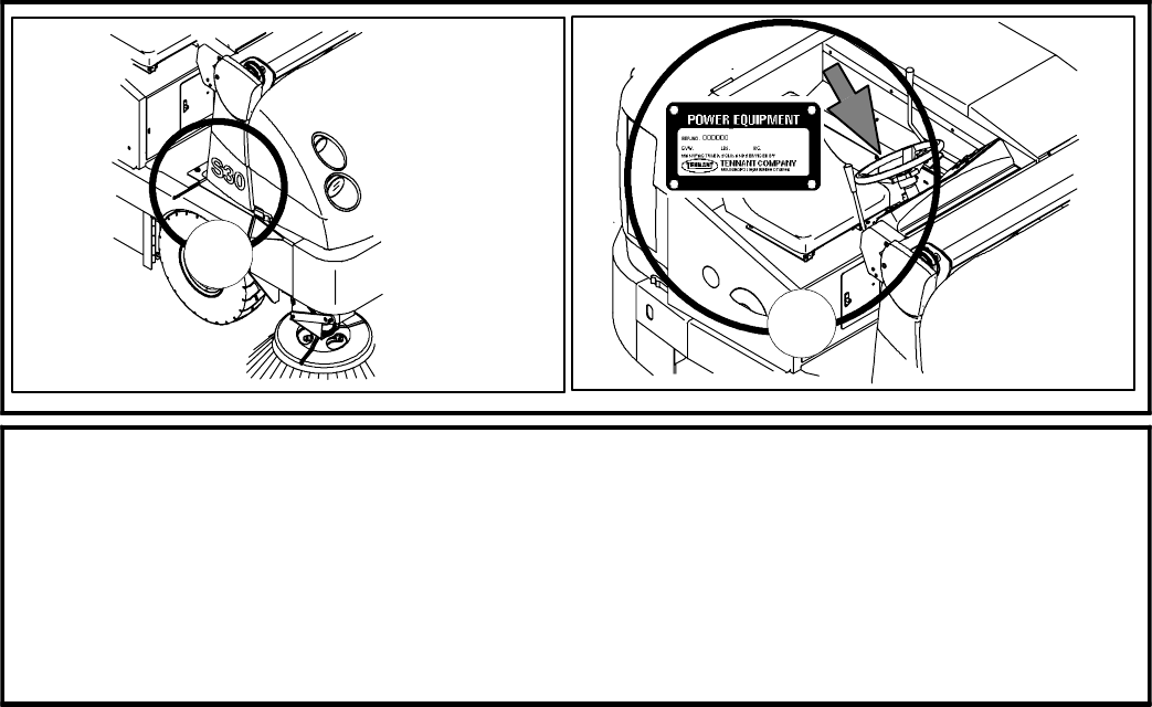
FOR REPLACEMENT PARTS
Identify machine model and serial number.
1. (A) Identify the machine model.
2. (B) Identify the machine serial number from the data plate.
Refer to the TENNANT Parts Manual.
NOTE: Only use TENNANT Company supplied or equivalent parts. Parts and supplies may be ordered
online, by phone, by fax or by mail.
Tennant Company
PO Box 1452
Minneapolis, MN 55440
Phone: (800) 553--8033 or (763) 513--2850
www.tennantco.com
Thermo--Sentry, Touch--N--Go, 1--STEP, Clean--Wedge, Variable Drain Valve, EasyOpen, Grip--N--Go, MaxPro@, Dura--Track, SmartRelease,
InstantAccess, Duramer, FaST--PAK and ErgoSpace are US registered and unregistered trademarks of Tennant Company.
Specifications and parts are subject to change without notice.
Copyright E2008 TENNANT Company, Printed in U.S.A.
Home
Find...
Go To..

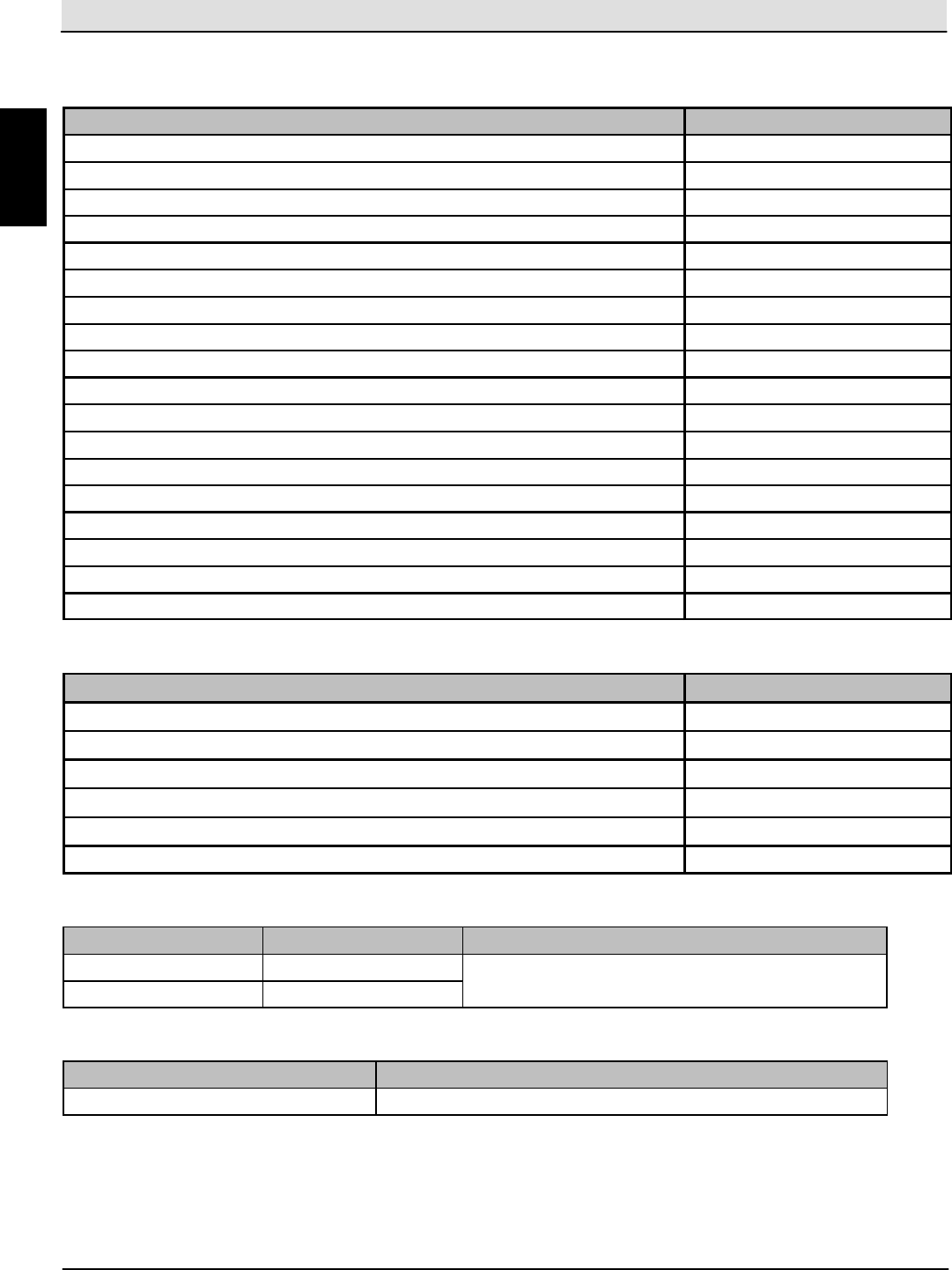
S30 SERVICE INFORMATION Table of Contents
S30 9004086 (4--08) iii
SAFETY PRECAUTIONS vi.............................
GENERAL MACHINE INFORMATION 1..................
GENERAL MACHINE DIMENSIONS/CAPACITIES 2...............
GENERAL MACHINE PERFORMANCE 2........................
HYDRAULIC SYSTEM 2.......................................
STEERING 2.................................................
POWER TYPE 3..............................................
BRAKING SYSTEM 4..........................................
TIRES 4......................................................
MACHINE DIMENSIONS 4.....................................
COMPONENT LOCATOR (1 OF 6) 5............................
MAINTENANCE & REPAIR 11...........................
MAINTENANCE CHECK POINTS 12.............................
MAINTENANCE CHART (1 OF 2) 13.............................
LUBRICATION 15..............................................
ENGINE OIL 15............................................
REAR WHEEL SUPPORT (S30 and S30XP) 15................
STEERING CYLINDER BEARING(S30 and S30XP) 15..........
HOPPER LIFT ARM BEARINGS 15...........................
STEERING ROD END (S30X4) 16............................
STEERING SPINDLES (S30X4) 16...........................
FRONT WHEEL BEARINGS 16..............................
HYDRAULICS 17...............................................
HYDRAULIC FLUID 17......................................
HYDRAULIC HOSES 18.....................................
ENGINE 18....................................................
COOLING SYSTEM 18......................................
AIR FILTER 20.............................................
FUEL FILTER (Gasoline) 20..................................
FUEL FILTER (LPG) 21......................................
FUEL FILTER (Diesel) 21....................................
FUEL LINES (Diesel) 21.....................................
PRIMING THE FUEL SYSTEM (Diesel) 22.....................
ELECTRONIC PRESSURE REGULATOR (LPG) 22.............
ENGINE BELT 22...........................................
TIMING BELT (Gasoline/LPG) 22.............................
SPARK PLUGS (Gasoline/LPG) 23............................
BATTERY 23..................................................
FUSES AND RELAYS 23........................................
RELAY PANEL FUSES AND RELAYS 23......................
ENGINE HARNESS FUSES AND RELAYS (Gasoline/LPG) 24...
ENGINE HARNESS RELAYS (Diesel) 25......................
CAB FUSES (CAB OPTION) 25..............................
REMOVING AND INSPECTING THE DUST FILTER 26.............
CLEANING THE DUST FILTER 27...............................
MAIN BRUSH 27...............................................
REPLACING OR ROTATING THE MAIN BRUSH 28............
CHECKING THE MAIN BRUSH PATTERN 29..................
ADJUSTING THE MAIN BRUSH TAPER 29....................
ADJUSTING THE MAIN BRUSH WIDTH 30....................
Home
Find...
Go To..

Table of Contents S30 SERVICE INFORMATION
S30 9004086 (4--08)
iv
MAINTENANCE & REPAIR cont’d............................
SIDE BRUSH 30...............................................
REPLACING THE SIDE BRUSH 30...........................
ADJUSTING THE SIDE BRUSH PATTERN 31..................
ROTATING AND REPLACING THE SIDE BRUSH GUARD 31....
SKIRTS AND FLAPS 32.........................................
HOPPER SKIRTS 32........................................
BRUSH DOOR SKIRTS 32...................................
REAR SKIRT 32............................................
RECIRCULATION FLAP 32..................................
SEALS 33.....................................................
BRUSH DOOR SEALS 33...................................
DUST FILTER SEALS 33....................................
HOPPER SEALS 33........................................
HOPPER INSPECTION DOOR SEALS 33.....................
FILTER CHAMBER INLET SEAL 34...........................
DUST RETURN SEALS 34...................................
VACUUM WAND DOOR SEALS (OPTION) 34..................
CYCLONIC PRE--FILTER SEALS 34..........................
BRAKES AND TIRES 35........................................
BRAKES 35................................................
PARKING BRAKE 35........................................
TIRES 35..................................................
REAR WHEEL 35...........................................
PROPELLING MOTOR 35.......................................
PUSHING, TOWING, AND TRANSPORTING THE MACHINE 36.....
PUSHING OR TOWING THE MACHINE 36....................
TRANSPORTING THE MACHINE 36..........................
MACHINE JACKING 38.........................................
STORAGE INFORMATION 38...................................
ELECTRICAL 39.......................................
ELECTRICAL SYMBOLS & ABBREVIATIONS 40..................
FUSES AND RELAYS (S30,S30XP,S30X4) 41.....................
RELAY PANEL FUSES AND RELAYS 41......................
ENGINE HARNESS FUSES AND RELAYS 42..................
CAB FUSES (CAB OPTION) 42..............................
S30 ELECTRICAL SCHEMATIC (1 OF 4) 43.......................
S30XP / S30X4 ELECTRICAL SCHEMATIC (1 OF 4) 47............
GASOLINE ENGINE HARNESS ELECTRICAL SCHEMATIC (1 OF 2) 51
LPG ENGINE HARNESS ELECTRICAL SCHEMATIC (1 OF 2) 53....
DIESEL ENGINE HARNESS ELECTRICAL SCHEMATIC 55.........
CAB HARNESS ELECTRICAL SCHEMATIC 56....................
S30 WIRE HARNESS DRAWING (1 OF 2) 57......................
S30XP / S30X4 WIRE HARNESS DRAWING (1 OF 3) 59...........
ALL MACHINES HOPPER COVER WIRE HARNESS DRAWING 62..
ALL MACHINES HOPPER WIRE HARNESS DRAWING 63..........
DIESEL ENGINE WIRE HARNESS DRAWING 64..................
CAB WIRE HARNESS DRAWING 65.............................
KEY SWITCH INFORMATION (S30,S30XP,S30X4) 66..............
KEY OFF POWER DISTRIBUTION (S30) 67.......................
KEY OFF POWER DISTRIBUTION (S30XP,S30X4) 68..............
Home
Find...
Go To..

S30 SERVICE INFORMATION Table of Contents
S30 9004086 (4--08) v
ELECTRICAL cont’d........................................
KEY ON POWER DISTRIBUTION (S30) 69........................
KEY ON POWER DISTRIBUTION (S30XP,S30X4) 70...............
MAIN&SIDEBRUSHESON(S30) 71............................
MAIN & SIDE BRUSHES ON (S30XP,S30X4) 72...................
VACUUM FAN ON (S30) 73.....................................
VACUUM FAN ON (S30XP,S30X4) 74.............................
FILTER SHAKER ON (S30) 75...................................
FILTER SHAKER ON (S30XP,S30X4) 76..........................
HOPPER LIFT (S30) 77.........................................
HOPPER LIFT (S30XP,S30X4) 78................................
HOPPER LOWER (S30) 79......................................
HOPPER LOWER (S30XP,S30X4) 80.............................
HOPPER DOOR OPEN -- AUTOMATIC (S30) 81...................
HOPPER DOOR OPEN -- MANUAL (S30) 82......................
HOPPER DOOR OPEN (S30XP,S30X4) 83........................
HOPPER DOOR CLOSE -- AUTOMATIC (S30) 84..................
HOPPER DOOR CLOSE (S30XP,S30X4) 85.......................
DISPLAY MODULE FAULT INDICATORS (S30) 86.................
FAULT INDICATORS (S30XP,S30X4) 87..........................
DASH FAULT INDICATORS (S30,S30XP,S30X4) 88................
OPERATING, MAINT., & DIAG. MODES (S30XP,S30X4) (1 OF 2) 89.
CIRCUIT BOARD PIN FUNCTIONS (S30XP,S30X4) 91.............
HYDRAULIC 93........................................
GENERAL INFORMATION (S30, S30XP, S30X4) (1 OF 2) 94........
HYDRAULIC SCHEMATIC (S30, S30XP) (1 OF 2) 96...............
HYDRAULIC SCHEMATIC (S30X4) (1 OF 2) 98....................
OVERALL HYDRAULIC HOSE DIAGRAM (S30) 100.................
OVERALL HYDRAULIC HOSE DIAGRAM (S30XP) 101..............
OVERALL HYDRAULIC HOSE DIAGRAM (S30X4) 102..............
RESERVOIR HOSE DIAGRAM 103................................
COOLER HOSE & TUBE DIAGRAM 104...........................
PUMPS DIAGRAM (S30, S30XP) 105..............................
PUMPS DIAGRAM (S30X4) 106...................................
VALVE BLOCK DIAGRAM (S30) 107...............................
VALVE BLOCK DIAGRAM (S30XP, S30X4) 108.....................
PRIORITY AND FLOW DIVIDER VALVE DIAGRAM (S30X4) 109......
LEFT SIDE BRUSH HYDRAULIC DIAGRAM (S30XP, S30X4) 110.....
MAIN BRUSH ON (S30, S30XP, S30X4) 111........................
MAIN BRUSH & SIDE BRUSH(ES) ON (S30, S30XP, S30X4) 112.....
HOPPER DOOR OPEN (S30, S30XP, S30X4) 113...................
HOPPER DOOR CLOSE (S30, S30XP, S30X4) 114..................
HOPPER LIFT (S30, S30XP, S30X4) 115...........................
HOPPER LOWER (S30, S30XP, S30X4) 116........................
VACUUM FAN ON (S30, S30XP, S30X4) 117.......................
MAIN BRUSH LOWER (S30XP, S30X4) 118........................
MAIN BRUSH & SIDE BRUSH(ES) LOWER (S30XP, S30X4) 119......
3--WHEEL STEERING SYSTEM (S30, S30XP) 120..................
4--WHEEL STEERING SYSTEM (S30X4) 121.......................
3--WHEEL PROPEL SYSTEM (S30, S30XP) 122....................
4--WHEEL PROPEL SYSTEM (S30X4) 123.........................
Home
Find...
Go To..

Safety Precautions S30 SERVICE INFORMATION
S30 9004086 (4--08)
vi
SAFETY PRECAUTIONS
The following precautions are used throughout this
manual as indicated in their description:
WARNING: To warn of hazards or unsafe
practices that could result in severe
personal injury or death.
CAUTION: To warn of unsafe practices that
could result in minor or moderate personal
injury.
FOR SAFETY: To identify actions that must be
followed for safe operation of equipment.
Do not use the machine other than described in this
Operator Manual. The machine is not designed for
use on public roads.
The following information signals potentially
dangerous conditions to the operator or equipment:
WARNING: Flammable materials or reactive
metals can cause an explosion or fire. Do
not pickup.
WARNING: Moving belt and fan. Keep away.
WARNING: Engine emits toxic gases.
Serious injury or death can result. Provide
adequate ventilation.
WARNING: Raised hopper may fall. Engage
hopper support pin.
WARNING: Lift arm pinch point. Stay clear
of hopper lift arms.
WARNING: Burn hazard. Hot surface. Do
NOT touch.
WARNING: Machine can emit excessive
noise. Hearing loss can result. Wear
hearing protection.
CAUTION: LPG engine will run for a few
seconds after key is turned off. Apply
parking brake before leaving machine.
WARNING: Accident may occur. Do not
operate vacuum or blower wand while
driving.
CALIFORNIA PROPOSITION 65 WARNING:
Engine exhaust from this product contains
chemicals known to the State of California
to cause cancer, birth defects, or other
reproductive harm.
FOR SAFETY:
1. Do not operate machine:
-- Unless trained and authorized.
-- Unless operator manual is read and
understood.
-- If it is not in proper operating condition.
-- In flammable or explosive areas.
-- In areas with possible falling objects
unless equipped with overhead guard.
2. Before starting machine:
-- Check for fuel, oil, and liquid leaks.
-- Keep sparks and open flame away from
refueling area.
-- Make sure all safety devices are in place
and operate properly.
-- Check brakes and steering for proper
operation.
3. When starting machine:
-- Keep foot on brake and directional pedal
in neutral.
4. When using machine:
-- Always wear safety belt (if so equipped)
-- Do not pick up burning or smoking
debris, such as cigarettes, matches or hot
ashes
-- Use brakes to stop machine.
-- Go slow on inclines and slippery
surfaces.
-- Use care when reversing machine.
-- Move machine with care when hopper is
raised.
-- Make sure adequate clearance is available
before raising hopper.
-- Do not carry passengers on machine.
-- Always follow safety and traffic rules.
-- Report machine damage or faulty
operation immediately.
Home
Find...
Go To..

S30 SERVICE INFORMATION Safety Precautions
S30 9004086 (4--08) vii
5. Before leaving or servicing machine:
-- Stop on level surface.
-- Set parking brake.
-- Turn off machine and remove key.
6. When servicing machine:
-- Avoid moving parts. Do not wear loose
jackets, shirts, or sleeves.
-- Block machine tires before jacking
machine up.
-- Jack machine up at designated locations
only. Support machine with jack stands.
-- Use hoist or jack that will support the
weight of the machine.
-- Wear eye and ear protection when using
pressurized air or water.
-- Disconnect battery connections before
working on machine.
-- Avoid contact with battery acid.
-- Avoid contact with hot engine coolant.
-- Do not remove cap from radiator when
engine is hot.
-- Allow engine to cool.
-- Keep flames and sparks away from fuel
system service area. Keep area well
ventilated.
-- Use cardboard to locate leaking hydraulic
fluid under pressure.
-- Use Tennant supplied or approved
replacement parts.
7. When loading/unloading machine onto/off
truck or trailer:
-- Turn off machine.
-- Use truck or trailer that will support the
weight of the machine.
-- Use winch. Do not drive the machine
onto/off the truck or trailer unless the load
height is 380 mm (15 in) or less from the
ground.
-- Set parking brake after machine is loaded.
-- Block machine tires.
-- Tie machine down to truck or trailer.
Home
Find...
Go To..

S30 SERVICE INFORMATION
S30 9004086 (4--08)
viii
Home
Find...
Go To..

S30 SERVICE INFORMATION General Machine Information
S30 9004086 (4--08) 1
GENERAL
MACHINE
INFORMATION
BEFORE CONDUCTING TESTS:
* Read and Follow ALL Safety Warnings and Precautions as mentioned
at the beginning of this manual
* Always unhook Battery when removing or replacing components
DURING TESTS:
* Call Technical Services if Diagnostic Time Exceeds One Hour With
Unknown Cause or Course of Action
NOTE: Troubleshooting charts may be shown with optional equipment. The optional equipment
may not be specified in these charts. Some machines may not be equipped with all components
shown.
G
Home
Find...
Go To..
General Machine Information S30 SERVICE INFORMATION
S30 9004086 (4--08)
2
SPECIFICATIONS
GENERAL MACHINE DIMENSIONS/CAPACITIES
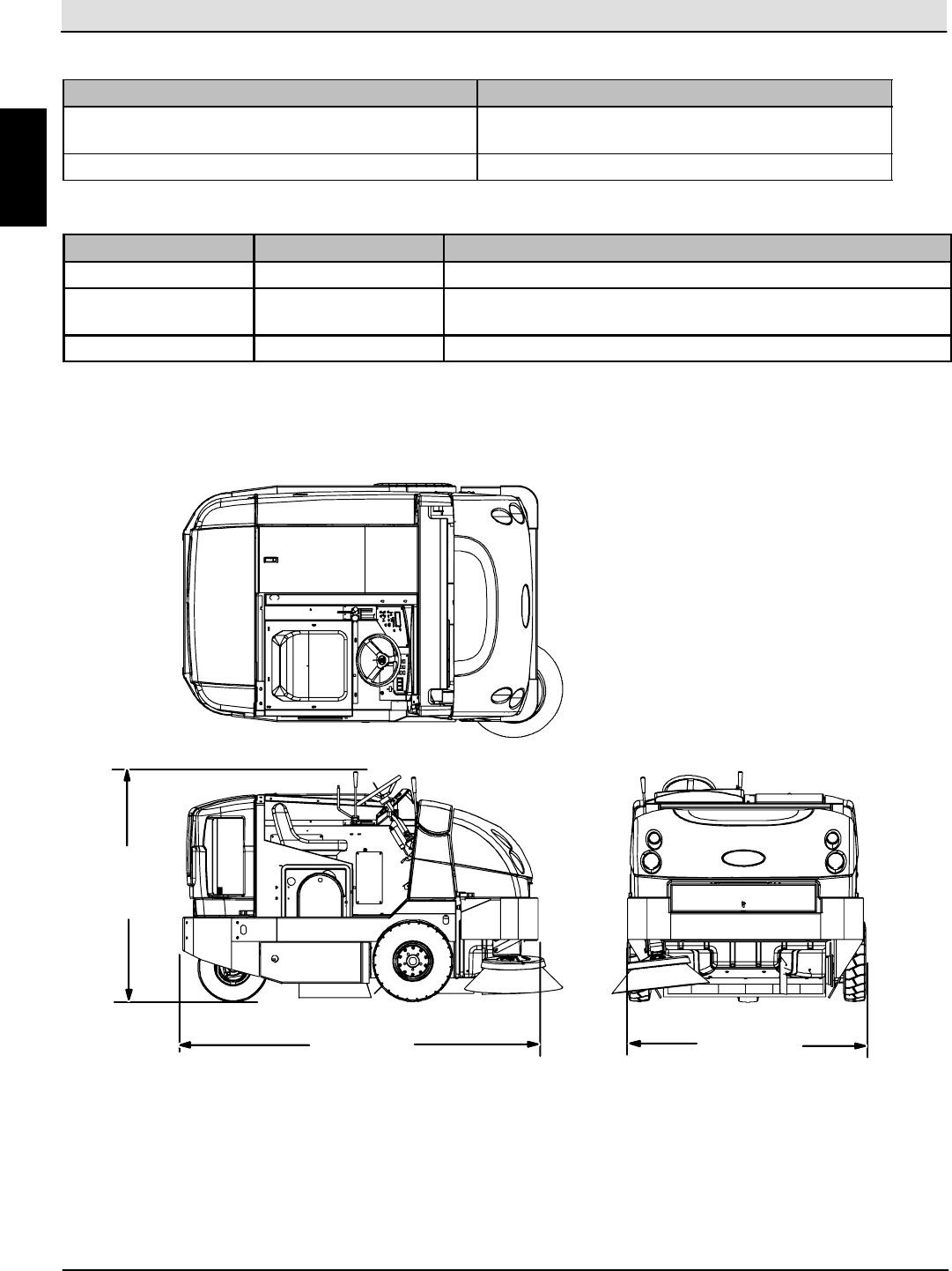
Item Dimension/capacity
Length 2360 mm (93 in)
Height 1475 mm (58 in)
Height (with overhead guard) 2095 mm (82.5 in)
Width/frame 1590 mm (62.5 in)
Cleaning path width (Single side brush) 1590 mm (62.5 in)
Cleaning path width (Dual side brushes) 2030 mm (80 in)
Main brush diameter 356 mm (14 in)
Side brush diameter 660 mm (26 in)
Debris hopper volume capacity (Plastic and Steel) 395 L (14 ft3)
Debris hopper weight capacity (Plastic) 490 kg (1080 lbs)
Debris hopper weight capacity (Steel) 545 kg (1200 lbs)
Dump height (variable to) 1525 mm (60 in)
Minimum ceiling dump height 2500 mm (98 in)
Weight -- empty 1595 Kg (3520 lbs)
GVWR 2585 Kg (5700 lbs)
Transport ground clearance 100 mm (4 in)
Operating Sound Level At Operator Ear 80 r1.5 dBA
Vibration level at steering wheel does not exceed 0.2 m/s@
GENERAL MACHINE PERFORMANCE
Item Measure
Minimum aisle turn 2870 mm (113 in)
Travel speed forward (maximum) (S30 and S30XP) 16.0 Km/h (10 mph)
Travel speed forward (maximum) (S30X4) 24.0 Km/h (15 mph)
Travel speed reverse (maximum) 5.0Km/h(3mph)
Maximum rated climb and descent (full hopper) 10_/18%
Maximum rated climb and descent (empty hopper) 14_/25%
HYDRAULIC SYSTEM
System Capacity Fluid Type
Hydraulic reservoir 38 L (10 gal) TENNANT part no. 65869 -- above 7_C(45_F)
Hydraulic total 45 L (12 gal) TENNANT part no. 65870 -- below 7_C(45_F)
STEERING
Type Power source
Rear wheel, hydraulic cylinder Hydraulic accessory pump
G
Home
Find...
Go To..
S30 SERVICE INFORMATION General Machine Information
S30 9004086 (4--08) 3
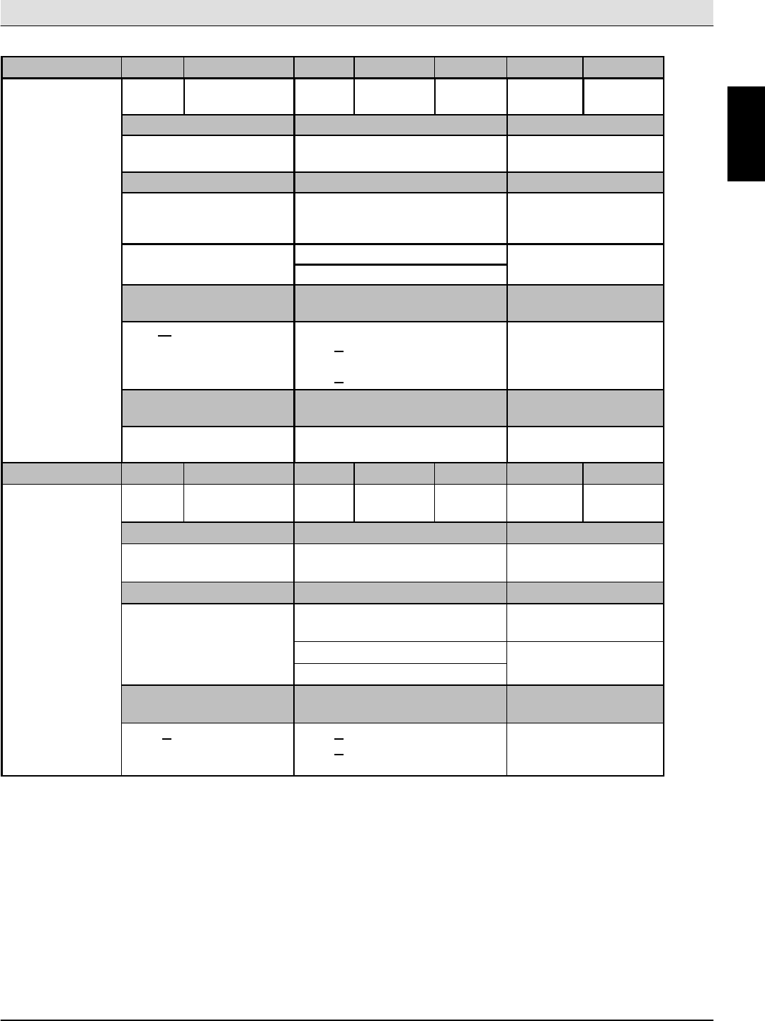
POWER TYPE
Engine Type Ignition Cycle Aspiration Cylinders Bore Stroke
GM 1.6 Piston Distributorless-
type spark
4Natural 479 mm
(3.11 in)
81.5 mm
(3.21 in)
Displacement Net power, governed Net power, maximum
1600 cc (98 cu in) 23.2 kw (32 hp) @ 2400 rpm 41 kw (55 hp) @
4000 rpm
Fuel Cooling system Electrical system
Gasoline, 87 octane
minimum, unleaded
Fuel tank: 42 L (11.2 gal)
Water/ethylene glycol
antifreeze
12 V nominal
LPG,
F
l
t
k
1
5
k
(
3
3
l
b
)
Total: 7.5 L (2 gal) 75 A alternator
,
Fuel tank: 15 kg (33 lb) Radiator: 3.8 L (1 gal)
Idle speed, no load (Fast) governed speed, under
load
Firing order
1350 + 50 rpm Normal sweep mode:
2000 + 50 rpm
Litter sweep mode:
2400 + 50 rpm
1--3--4--2
Spark plug gap Valve clearance, cold Engine lubricating oil
with filter
1 mm (0.035 in) No Adjustment
OHC Engine
3.5 L (3.7 qt) 5W30
SAE--SG/SH
Engine Type Ignition Cycle Aspiration Cylinders Bore Stroke
Kubota V1505--B Piston Diesel 4Natural 478 mm
(3.07 in)
78.4 mm
(3.08 in)
Displacement Net power, governed Net power, maximum
1500 cc (91.4 cu in) 24.6 kw (34 hp) @ 2400 rpm 27.2 kw (37.5 hp) @
3000 rpm
Fuel Cooling system Electrical system
Diesel
Fuel tank: 42 L (11.2 gal)
Water/ethylene glycol
antifreeze
12 V nominal
Total: 7.5 L (2 gal) 75 A alternator
Radiator: 3.8 L (1 gal)
Idle speed, no load (Fast) governed speed, under
load
Engine lubricating oil
without filter
1350 +50 rpm 2000 +50 rpm
2400 +50 rpm
6 L (6.35 qt)
Diesel rated engine oil
above CD grade only
G
Home
Find...
Go To..
General Machine Information S30 SERVICE INFORMATION
S30 9004086 (4--08)
4
BRAKING SYSTEM
Type Operation
Service brakes Mechanical drum brakes (2), one per front wheel,
cable actuated
Parking brake Utilize service brakes, cable actuated
TIRES
Location Type Size
Front (2) Solid 127 mm x 535 mm (5 in x 21 in)
Rear (1)
(S30 and S30XP)
Pneumatic 115 mm x 470 mm (4.5 in x 18.5 in)
Rear (2) (S30X4) Foam Fill 115 mm x 410 mm (4.5 in x 16 in)
MACHINE DIMENSIONS
1590 mm
(62.5 in)
1475 mm
(58 in)
2360 mm
(93 in)
354726
G
Home
Find...
Go To..
S30 SERVICE INFORMATION General Machine Information
S30 9004086 (4--08) 5
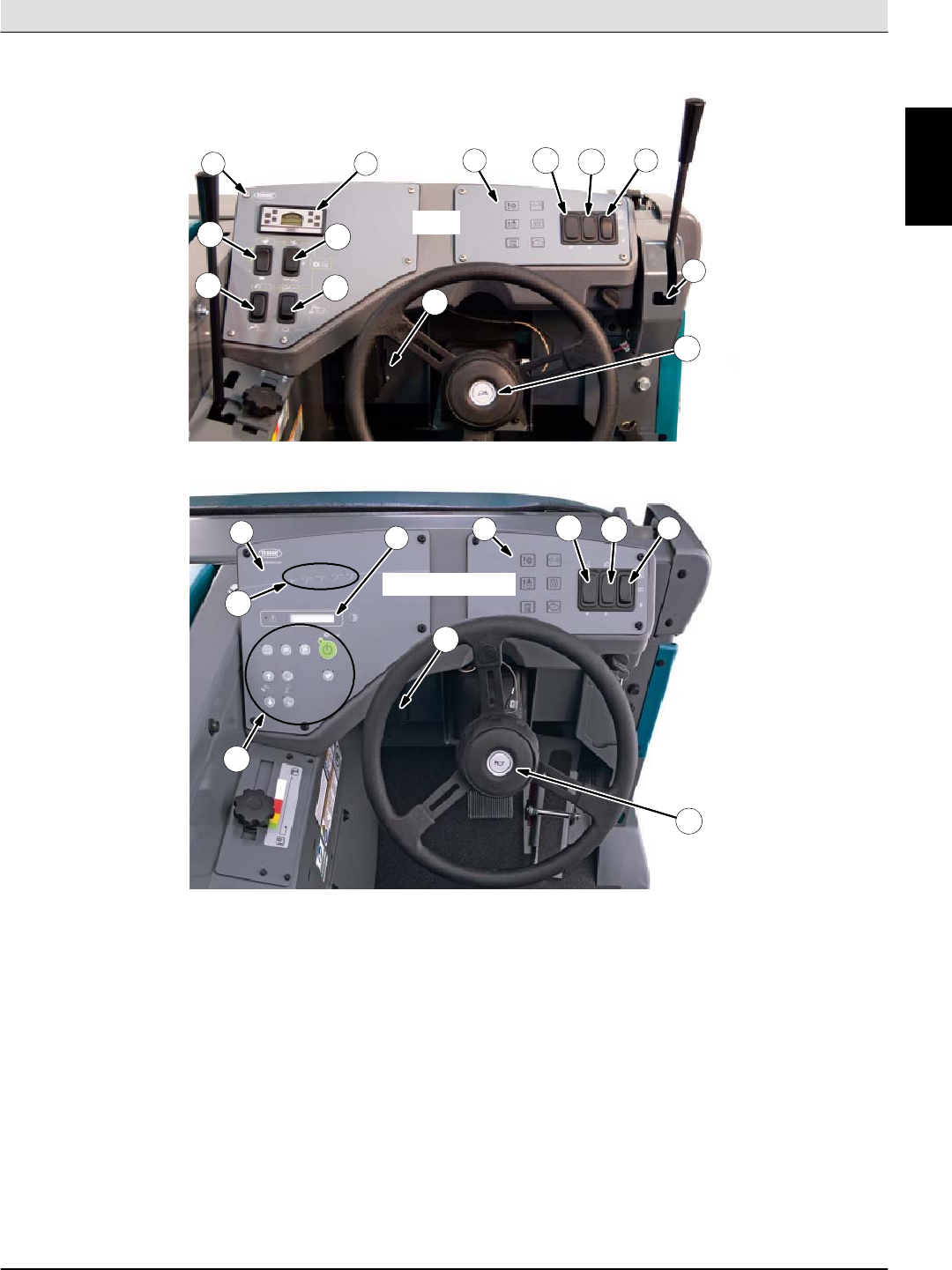
Component Locator
(page 1 of 6)
S30
S30XP/S30X4
1. Instrument panel
2. Indicator panel
3. Dash Fault Indicator lights (LP8,LP9,LP10,LP11,LP12)
4. Wand switch (option) (SW21)
5. Side brush light switch (option) (SW17)
6. Operating / hazard light switch (SW12)
7. Side Brush Lever Switch (SW7)
8. Horn button (SW19)
9. Hopper raise / lower switch (SW22)
10. Engine speed switch (SW6)
11. Vacuum fan / filter shaker switch (SW18)
12. Hopper door switch (SW3)
13. Sweeping function buttons (see next page)
14. Supervisor control buttons (see next page)
15. Fuse & relay panel
3
11
1
1
13
2
2346
5
8
10
12
9
14
15
15
8
46
5
7
G
Home
Find...
Go To..
General Machine Information S30 SERVICE INFORMATION
S30 9004086 (4--08)
6
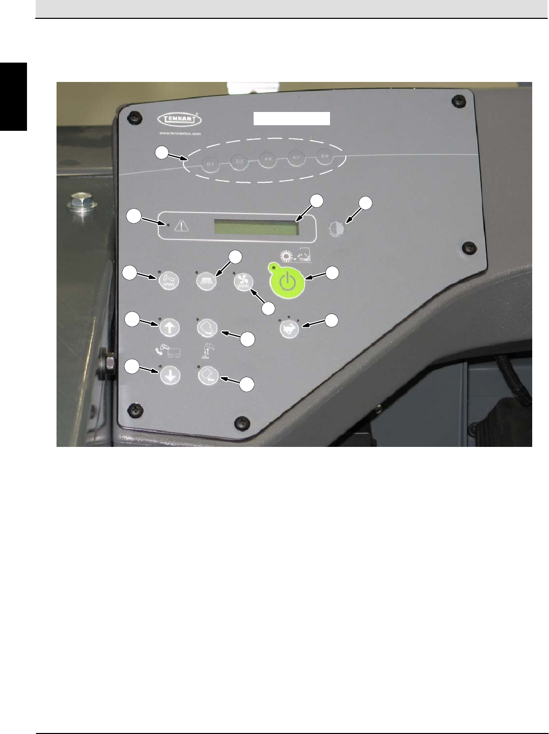
Component Locator
(page 2 of 6)
8
6
10
23
4
5
7
9
11
12
13
1
1. Supervisor control buttons
2. Hour meter / fuel indicator / fault code indicator
3. Contrast control button
4. 1--STEP sweep button
5. Engine speed button
6. Vacuum fan button
7. Side brush button
8. Hopper door open button
9. Hopper door close button
10. Hopper lower button
11. Hopper raise button
12. Filter shaker button
13. Fault indicator light
S30XP/S30X4
G
Home
Find...
Go To..
S30 SERVICE INFORMATION General Machine Information
S30 9004086 (4--08) 7
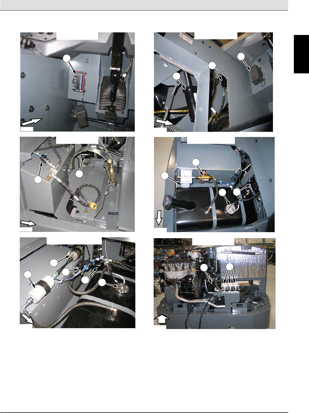
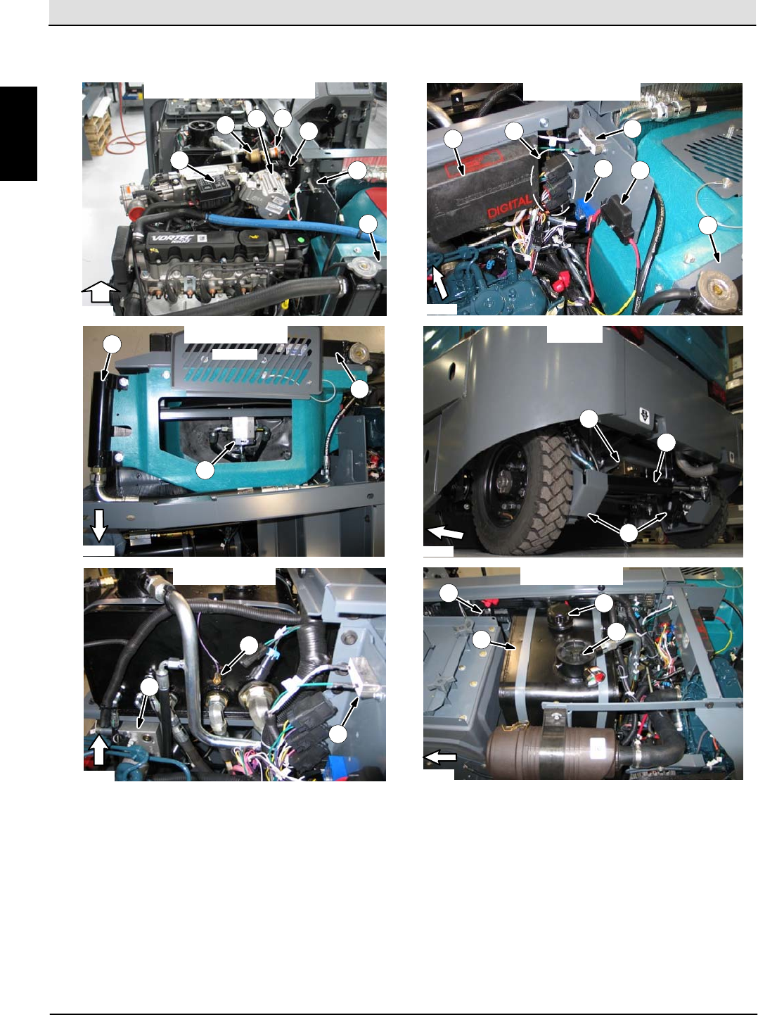
Component Locator
(page 3 of 6)
1
All machines
LPG Engines Diesel Engines
1. Fuse & relay panel
2. Main Brush Lift Cylinder (CYL4)
3. Steering Priority Valve (S30X4 Only)
4. Low Fuel Pressure Switch (SW2 or S3)
5. Steering Cylinder (S30/S30XP Only -- CYL5)
6. Fuel Filter
5
5
4
1
2
3
9
7
Gasoline Engines
6
58
All machines
10
S30XP/S30X4
6
7
8
11
7. Fuel Pump (PUMP1)
8. Fuel Sending Unit (SNDR1 or S2)
9. Fuel Pressure Regulator
10. Propel System Hydraulic Pump (PUMP1)
11. Accessory Hydraulic Pumps (PUMP2,3,&4)
FRONT FRONT
FRONT FRONT
FRONT FRONT
G
Home
Find...
Go To..
General Machine Information S30 SERVICE INFORMATION
S30 9004086 (4--08)
8
Component Locator
(page 4 of 6)
1. Engine Fuse & Relay Panel
2. Fuel Filter (LPG Only)
3. Electronic Fuel Pressure Regulator (LPG Only)
4. Fuel Lockoff Valve (LPG Only)
5. Engine Control Module
6. Alternator Pull--Up Resistor (R1)
7. Engine Radiator
8. Engine Speed Governor Controller (CNTRL2)
9. Diesel Engine Control Relays (M9,10,11, &12)
10. Starter Engagement Timer (TMR2)
11. Glow Plugs 40A Fuse (F13)
Diesel Engines
11
7
10
Gasoline/LPG Engines
1
3
245
6
12
7
13
All machines
All machines
15
14
S30X4
16
All machines
19
20
21
22
FRONT FRONT
FRONT FRONT
FRONT
TOP VIEW
FRONT
18
17
6
9
86
12. Hydraulic Oil Cooler (HTX)
13. Engine Fan Motor (MTR6)
14. Propel System Flow Divider Valve
15. Steering Cylinder (CYL5)
16. Left & Right Propel Motors (MTR6 & MTR7)
17. Hydraulic Valve Manifold
18. Hydraulic Oil Temp. Sender (SNDR3 or S7)
19. Main Brush Lever Switch (S30 Only -- SW5)
20. Hydraulic Oil Reservoir (RES1)
21. Reservoir Cap & Oil Level Indicator
22. Hydraulic Oil Filter (FLTR)
7
G
Home
Find...
Go To..
S30 SERVICE INFORMATION General Machine Information
S30 9004086 (4--08) 9
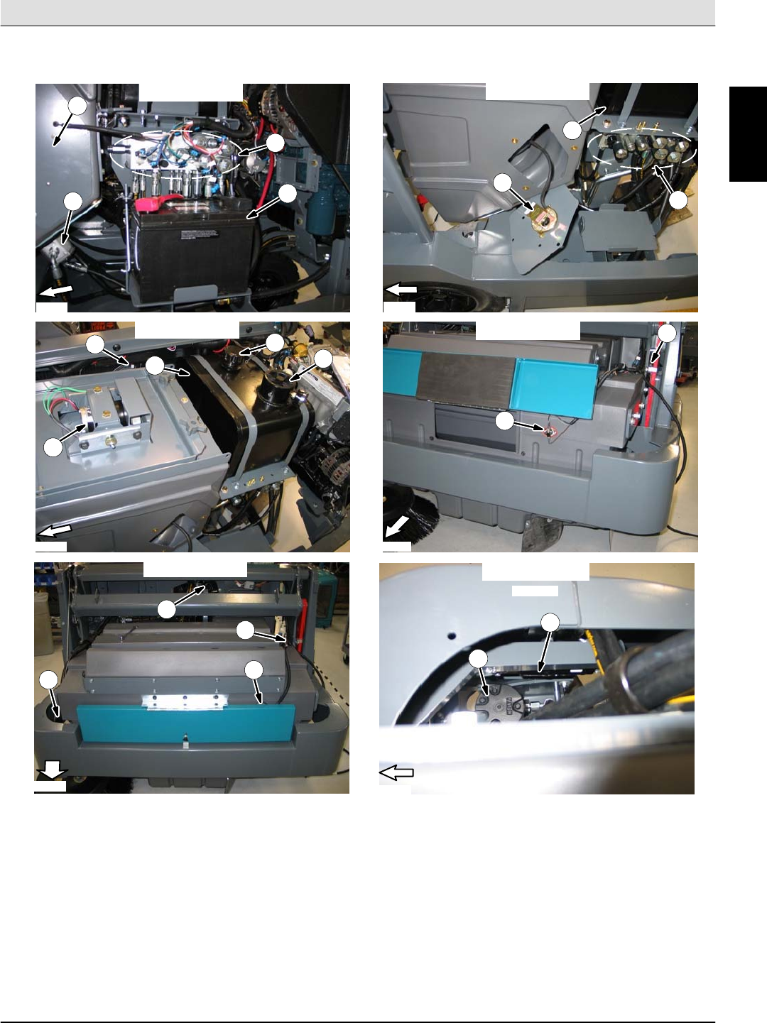
Component Locator
(page 5 of 6)
All machines
43
2
1
9
All machines
1
2
3
All machines
7
8
9
5
All machines
All machines
11
11
12
10
13
13
S30XP/S30X4
FRONT
FRONT
FRONT
FRONT
FRONT FRONT
1
6
10 14
TOP VIEW
1. Clogged Dust Filter Switch (SW8 or S8)
2. Hydraulic Valve Manifold
3. Battery
4. Vacuum Fan Motor (MTR5)
5. Dust Filter Shaker Motor (MTR1)
6. Main Brush Lever Switch (S30 Only -- SW5)
7. Hydraulic Oil Reservoir (RES1)
8. Reservoir Cap & Oil Level Indicator
9. Hydraulic Oil Filter (FLTR)
10. Hopper Position Switch (SW16)
11. Thermo--Sentry Switch (SW14)
12. Horn (LS1)
13. Side Brush Motor (MTR2)
14. Side Brush Lift Cylinder (CYL3)
G
Home
Find...
Go To..
General Machine Information S30 SERVICE INFORMATION
S30 9004086 (4--08)
10
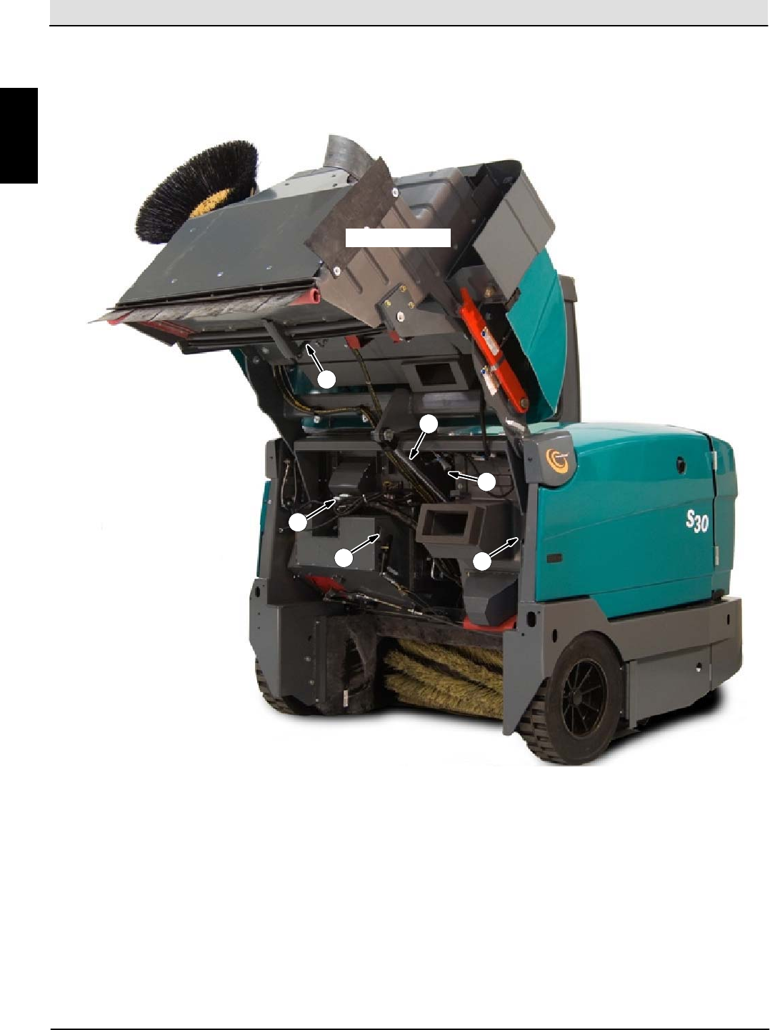
Component Locator
(page 6 of 6)
All machines
6
1
2
3
1. Hopper Door Cylinder (CYL1)
2. Hopper Lift Cylinder (CYL2)
3. Horn (LS1)
4. Hopper Position Switch (SW16)
5. Brake Switch (S15)
6. Steering Valve
54
G
Home
Find...
Go To..

S30 SERVICE INFORMATION Maintenance & Repair
S30 9004086 (4--08) 11
MAINTENANCE
& REPAIR
BEFORE CONDUCTING TESTS:
* Read and Follow ALL Safety Warnings and Precautions as mentioned
at the beginning of this manual
* Always unhook Battery when removing or replacing electrical
components
DURING TESTS:
* Call Technical Services if Diagnostic Time Exceeds One Hour With
Unknown Cause or Course of Action
NOTE: Troubleshooting charts may be shown with optional equipment. The optional equipment
may not be specified in these charts. Some machines may not be equipped with all components
shown.
M
Home
Find...
Go To..
Maintenance & Repair S30 SERVICE INFORMATION
S30 9004086 (4--08)
12
MAINTENANCE
1
2
3
4
5
6
7
8
9
10
11
12
13
14
5
15
M
Home
Find...
Go To..
MAINTENANCE
34 S30 Gas/LPG 9004080 (9−2012)
MAINTENANCE CHART
Interval Key Description Procedure Lubricant/
Fluid
No. of
Service
Points
Daily 1 Engine Check oil level EO 1
Check coolant level in reservoir WG 1
Check air filter indicator − 1
2Hydraulic fluid reservoir Check fluid level HYDO 1
3Dust filter Shake to clean − 1
4Main brush compartment
skirts Check for damage, wear, and
adjustment − All
5Hopper skirts Check for damage, wear, and
adjustment − All
6Main brush Check for damage and wear − 1
7Side brush Check for damage and wear − 1
50 Hours 6Main brush Rotate end-for-end and check
pattern − 1
8Rear wheel Torque wheel nuts (after initial
50 hours only) − 1
9 Battery Clean and tighten battery cable
connections (after initial 50
hours only)
− 1
1 Engine Check belt tension − 1
100 Hour
s
1 Engine Change oil and filter EO 1
Drain oil from electronic pressure
regulator (EPR) − 1
3Dust filter Check for damage, clean or
replace − 1
10 Radiator Clean core exterior − 1
10 Hydraulic cooler Clean core exterior HYDO 1
8Rear tire Check pressure − 1
− Seals Check for damage or wear − All
200 Hour
s
10 Radiator hoses and clamps Check for tightness and wear − All
11 Parking brake Check adjustment − 1
11 Brake pedal Check adjustment − 1
12 Rear wheel support
bearings Lubricate SPL 2
12 Steering cylinder bearings Lubricate SPL 1
13 Hopper lift arm bearings Lubricate SPL 2
14 Side brush guard Rotate 90_− 1
Home
Find...
Go To..
MAINTENANCE
35
S30 Gas/LPG 9004080 (3−2012)
Interval Key Description Procedure Lubricant/
Fluid
No. of
Service
Points
400 Hour
s
1 Engine Clean and re−gap or replace
spark plugs − 4
Replace fuel filter (Gas/LPG) − 1
15 Front wheels Adjust and repack bearings SPL 2
800 Hour
s
2Hydraulic fluid reservoir Replace filler cap − 1
1 Engine Check timing belt − 1
−Hydraulic hoses Check for wear and damage − All
10 Cooling system Flush WG 1
8Propelling motor Torque shaft nut − 1
8Rear wheel Torque wheel nuts − 1
9 Battery Clean and tighten battery cable
connections − 1
1200
Hours 2Hydraulic fluid filter * Change filter element − All
2000
Hours 1 Engine Replace timing belt 1
2400
Hours 2Hydraulic fluid reservoir * Replace suction strainer − 1
* Change hydraulic fluid HYDO 1
NOTE: Change the hydraulic fluid, filter, and suction strainer, indicated (*), after every 800 hours for
machines NOT originally equipped with TennantTrue premium hydraulic fluid. (See Hydraulics section).
LUBRICANT/FLUID
EO Engine oil, 5W30 SAE−SG/SH only.....
HYDO TennantTrue premium hydraulic fluid or equivalent.
WG Water and ethylene glycol anti-freeze, −34_ C (−30_ F)...
SPL Special lubricant, Lubriplate EMB grease (Tennant part number 01433−1)...
NOTE: More frequent maintenance intervals may be required in extremely dusty conditions.
Home
Find...
Go To..
S30 SERVICE INFORMATION Maintenance & Repair
S30 9004086 (4--08) 15
LUBRICATION
ENGINE OIL
Check the engine oil level daily. Change the oil and oil
filter after every 100 hours of operation.
GAS/LPG
Gas/LPG engines: Fill the engine with oil until the oil
is between the indicator marks on the dipstick. DO
NOT fill past the top indicator mark. The engine oil
capacity is 3.5 L (3.7 qt) with oil filter.
DIESEL
Diesel engines: Fill the engine with oil until the oil is
between the indicator marks on the dipstick. DO NOT
fill past the top indicator mark. The engine oil capacity
is 6 L (6.35 qt) with oil filter.
REAR WHEEL SUPPORT (S30 and S30XP)
Lubricate the rear wheel support bearings after every
200 hours of operation.
STEERING CYLINDER BEARING
(S30 and S30XP)
Lubricate the steering cylinder after every 200 hours
of operation.
HOPPER LIFT ARM BEARINGS
Lubricate the hopper lift arm bearings after every 200
hours of operation.
M
Home
Find...
Go To..
Maintenance & Repair S30 SERVICE INFORMATION
S30 9004086 (4--08)
16
STEERING ROD END (S30X4)
Lubricate the steering rod end and spindles after
every 200 hours of operation.
STEERING SPINDLES (S30X4)
Lubricate the steering after every 200 hours of
operation.
FRONT WHEEL BEARINGS
Repack and adjust the front wheel bearings every 400
hours of operation.
M
Home
Find...
Go To..
MAINTENANCE
37
S30 Gas/LPG 9004080 (12−2009)
HYDRAULICS
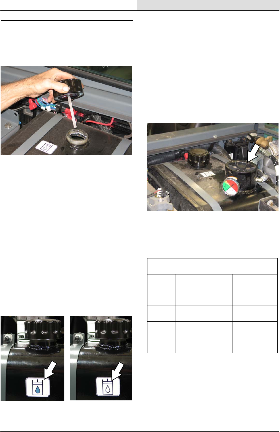
Check the hydraulic fluid level at operating
temperature daily. The hopper must be down
when checking hydraulic fluid level.
A filler cap is mounted on top of the reservoir. It
has a built-in breather and fluid level dipstick.
Replace the cap after every 800 hours of
operation.
Lubricate the filler cap gasket with a film of
hydraulic fluid before putting the cap back on the
reservoir.
ATTENTION! Do not overfill the hydraulic fluid
reservoir or operate the machine with a low
level of hydraulic fluid in the reservoir.
Damage to the machine hydraulic system may
result.
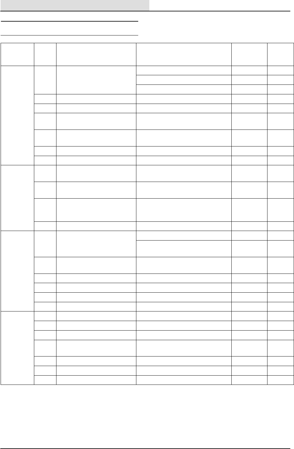
Drain and refill the hydraulic fluid reservoir with
new TennantTrue premium hydraulic fluid after
every 2400 hours of operation. Machines have a
blue colored drop (left photo) on the hydraulic fluid
label if originally equipped with TennantTrue
premium hydraulic fluid.
TennantTrue Fluid Previous Fluid
NOTE: Change the hydraulic fluid, filter, and
suction strainer after every 800 hours for ALL
machines that have NOT consistently used
TennantTrue premium hydraulic fluid or
equivalent.
The reservoir has a built-in strainer outlet that
filters hydraulic fluid before it enters the system.
Replace the strainer after every 2400 hours of
operation.
Replace the hydraulic fluid filter after every 1200
hours of operation or if the hydraulic reservoir
gauge is in the yellow/red zone when the reservoir
hydraulic fluid is approximately 32_C (90_ F).
HYDRAULIC FLUID
There are two fluids available for different
temperature ranges:
TennantTrue premium
hydraulic fluid (Extended Life)
Part
number Ambient
temperature ISO
Grade Ca-
pacity
1057710 above 7_C (45_F) 100 3.8 L
(1 gal)
1057711 above 7_C (45_F) 100 19 L
(5 gal)
1057707 below 7_C (45_F) 32 3.8 L
(1 gal)
1057708 below 7_C (45_F) 32 19 L
(5 gal)
If using a locally-available hydraulic fluid, be sure
the specifications match Tennant hydraulic fluid
specifications. Substitute fluids can cause
premature failure of hydraulic components.
ATTENTION! Hydraulic components depend
on system hydraulic fluid for internal
lubrication. Malfunctions, accelerated wear,
and damage will result if dirt or other
contaminants enter the hydraulic system.
Home
Find...
Go To..
Maintenance & Repair S30 SERVICE INFORMATION
S30 9004086 (4--08)
18
HYDRAULIC HOSES
Check the hydraulic hoses after every 800 hours of
operation for wear or damage.
FOR SAFETY: When servicing machine, use
cardboard to locate leaking hydraulic fluid under
pressure.
High pressure fluid escaping from a very small hole
can almost be invisible, and can cause injury.
00002
Contact appropriate personnel if a leak is discovered.
ATTENTION: Only use TENNANT supplied
hydraulic hoses or equivalent rated hydraulic
hoses.
ENGINE
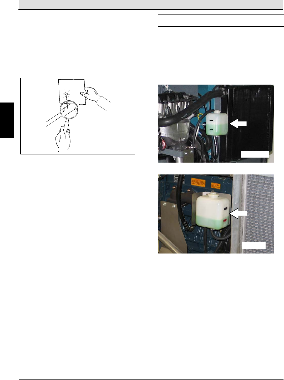
COOLING SYSTEM
FOR SAFETY: When servicing machine, avoid
contact with hot engine coolant.
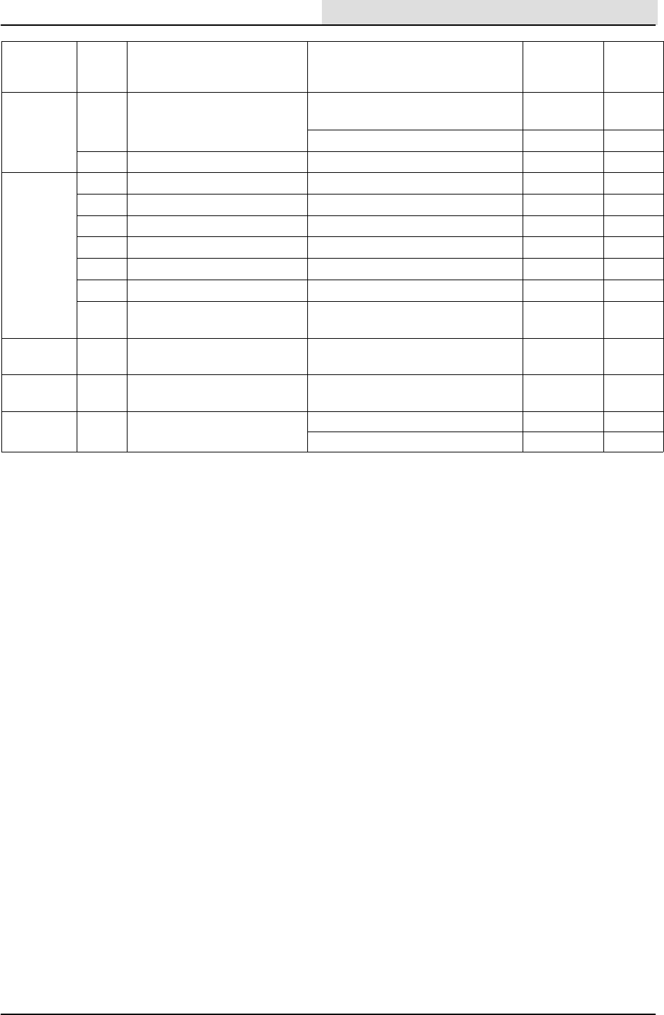
Check the coolant level in the reservoir daily. The
coolant level must be between the two indicator
marks when the engine is cold.
GAS/LPG
DIESEL
FOR SAFETY: When servicing machine, do not
remove cap from radiator when engine is hot.
Allow engine to cool.
Check the coolant level in the radiator after every 100
hours of operation. Refer to the label on the coolant
container for water/coolant mixing instructions.
Flush the radiator and the cooling system after every
800 hours of operation.
M
Home
Find...
Go To..
S30 SERVICE INFORMATION Maintenance & Repair
S30 9004086 (4--08) 19
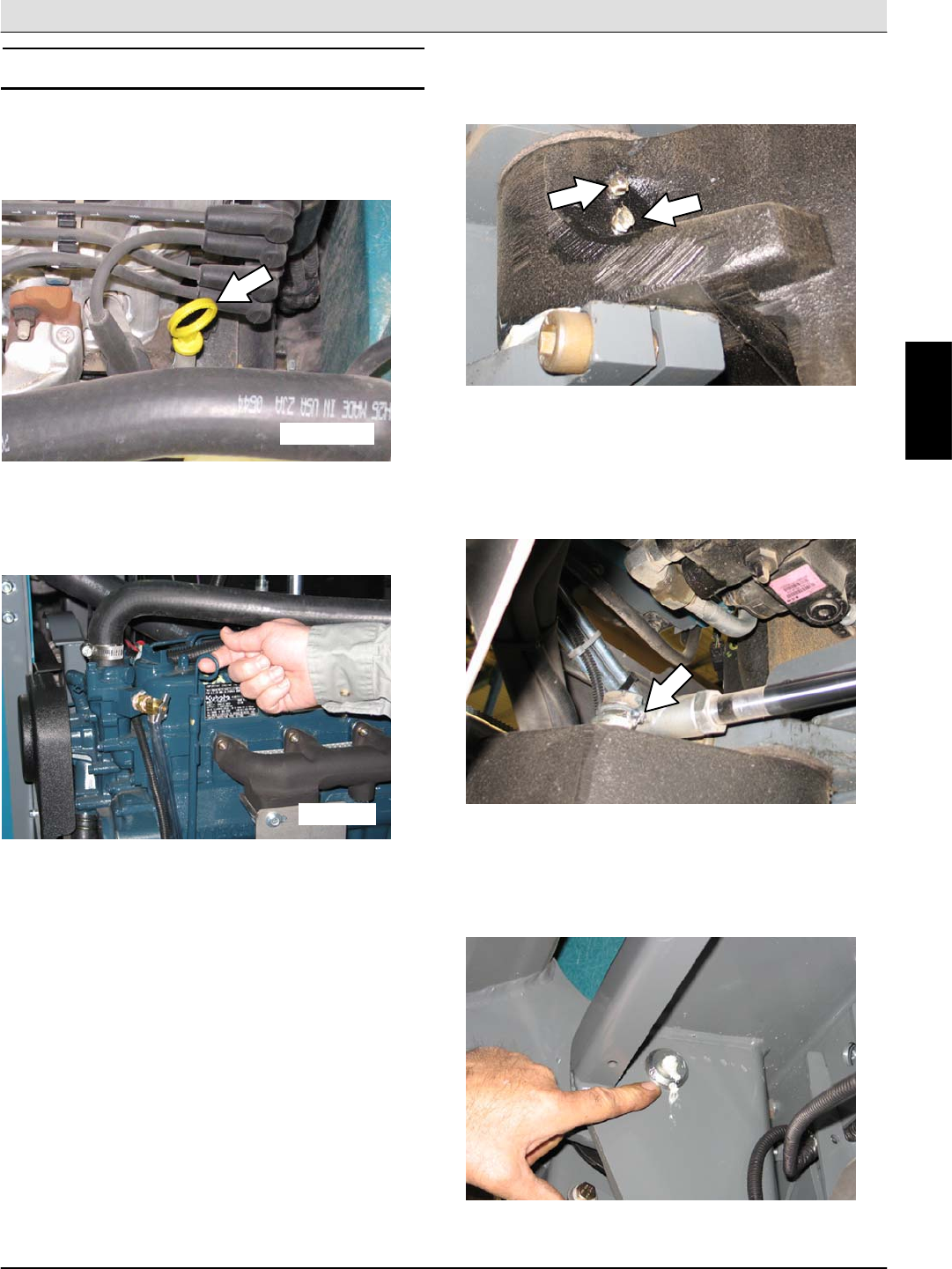
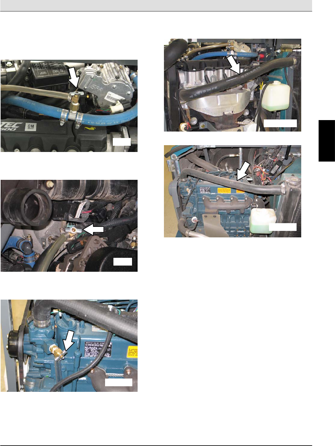
The cooling system must be completely filled with
coolant to keep the engine from overheating. When
filling the cooling system, open the drain cocks to
bleed the air from the system.
Location of drain cock on LPG machines.
LPG
Location of drain cock on gasoline machines.
GAS
Location of drain cock on diesel machines.
DIESEL
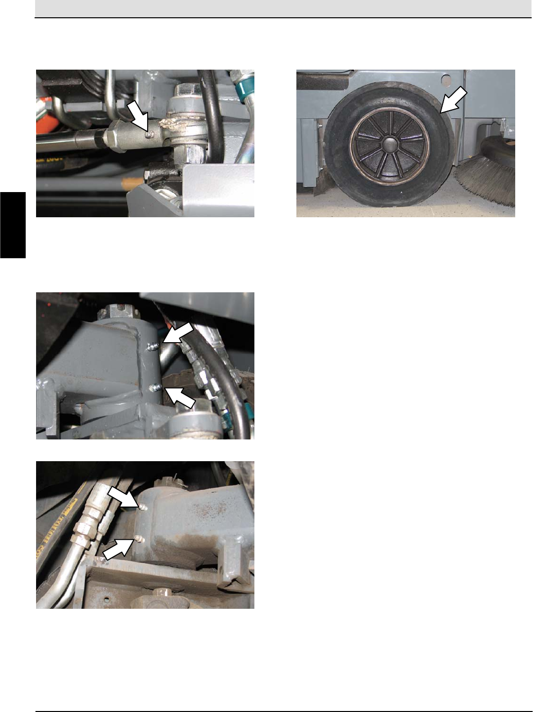
Check the radiator hoses and clamps after every 200
hours of operation. Tighten loose clamps. Replace
damaged hoses and clamps.
GAS/LPG
DIESEL
M
Home
Find...
Go To..
Maintenance & Repair S30 SERVICE INFORMATION
S30 9004086 (4--08)
20
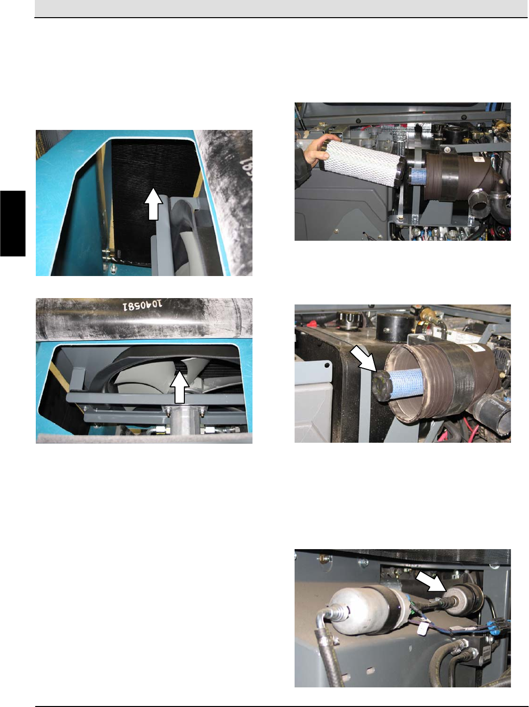
Check the radiator core exterior and hydraulic cooler
fins for debris after every 100 hours of operation.
Blow or rinse (with low pressure air or water) all dust
through the grille and radiator fins, in the opposite
direction of normal air flow. Be careful to not bend the
cooling fins when cleaning. Clean thoroughly to
prevent the fins from becoming encrusted with dust.
To avoid cracking the radiator, allow the radiator and
cooler fins to cool before cleaning.
FOR SAFETY: When servicing machine, wear eye
and ear protection when using pressurized air or
water.
AIR FILTER
Replace the primary air filter after every 400 hours of
operation.
NOTE: Clean the filter more often if machine is used
in extremely dusty conditions.
Replace the safety filter element after the primary has
been changed three times. Do not remove the safety
filter element from the housing unless it is restricting
air flow.
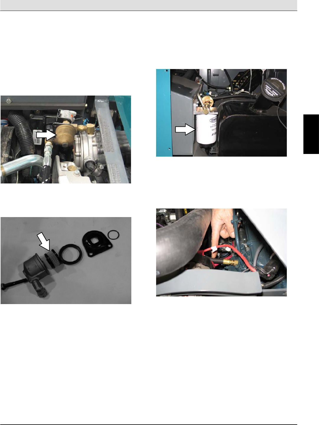
FUEL FILTER (Gasoline)
Replace the gasoline fuel filter after every 800 hours
of operation.
FOR SAFETY: When servicing machine, keep
flames and sparks away from fuel system service
area. Keep area well ventilated.
M
Home
Find...
Go To..
S30 SERVICE INFORMATION Maintenance & Repair
S30 9004086 (4--08) 21
FUEL FILTER (LPG)
NOTE: Close the LPG tank service valve and operate
the engine until it stops from lack of fuel before
working on the LPG fuel system.
Replace the LPG fuel filter after every 400 hours of
operation.
FOR SAFETY: When servicing machine, keep
flames and sparks away from fuel system service
area. Keep area well ventilated.
Disassemble the fuel lock off valve to access the LPG
fuel filter.
FUEL FILTER (Diesel)
Replace the fuel filter after every 800 hours of
operation.
FOR SAFETY: When servicing machine, keep
flames and sparks away from fuel system service
area. Keep area well ventilated.
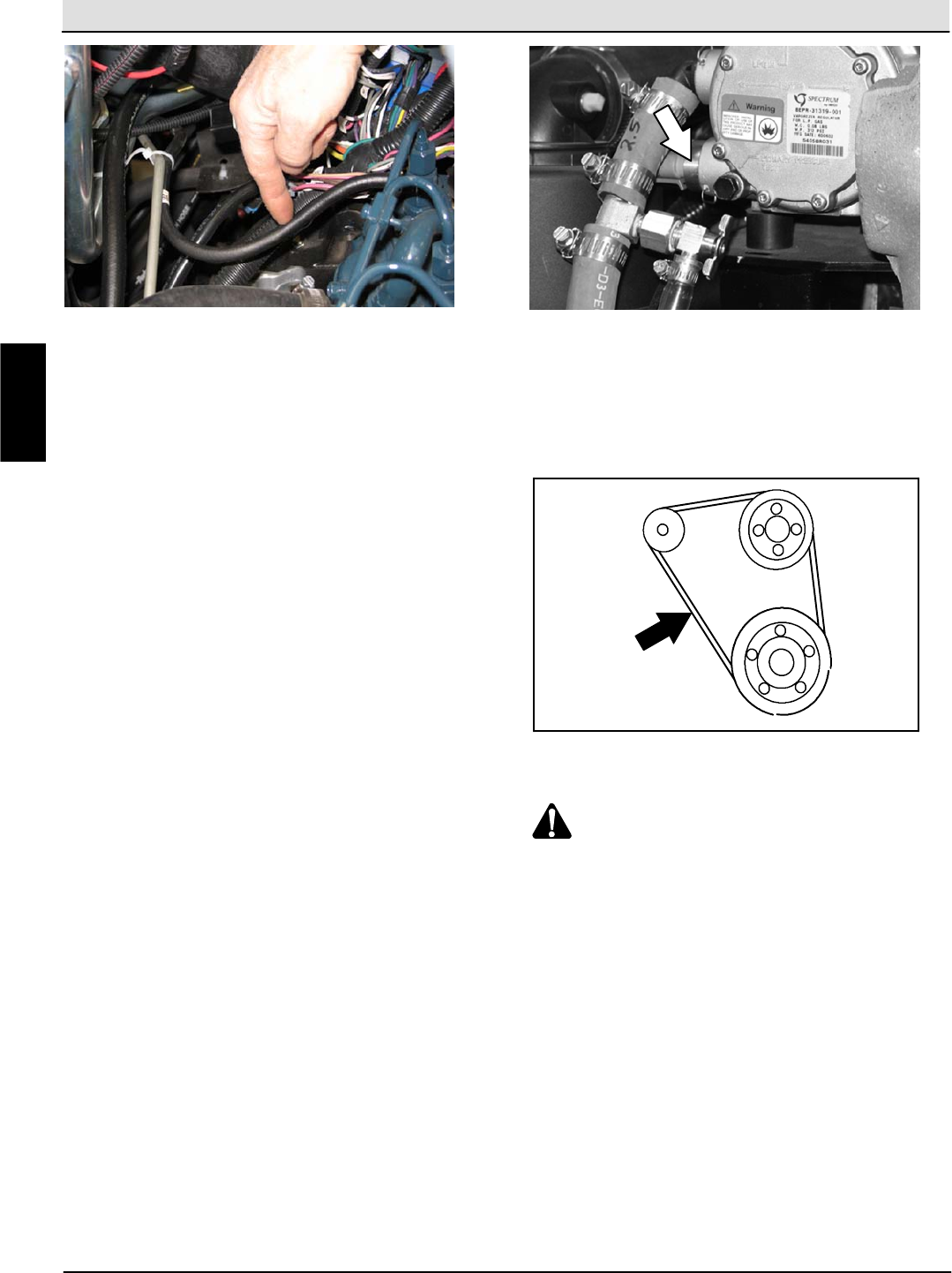
FUEL LINES (Diesel)
Check the fuel lines every 50 hours of operation. If
the clamp band is loose, apply oil to the screw of the
band and securely tighten the band.
M
Home
Find...
Go To..
Maintenance & Repair S30 SERVICE INFORMATION
S30 9004086 (4--08)
22
The rubber fuel lines can become worn--out whether
the engine has been used much or not. Replace the
fuel lines and clamp bands every two years.
FOR SAFETY: When servicing machine, keep
flames and sparks away from fuel system service
area. Keep area well ventilated.
If the fuel lines and clamp bands are found worn or
damaged before two years’ time; replace or repair
them at once. Bleed the fuel system after
replacement of any fuel lines, see PRIMING THE
FUEL SYSTEM. When the fuel lines are not installed,
plug both ends with clean cloth or paper to prevent
dirt from entering the lines. Dirt in the lines can cause
fuel injection pump malfunction.
PRIMING THE FUEL SYSTEM (Diesel)
Typical diesel fuel systems require priming to remove
pockets of air from the fuel lines and fuel
components. This is usually required after running out
of fuel, changing fuel filter elements or repairing a fuel
system component. Air in the fuel prevents smooth
engine operation.
This fuel system however is self-priming. The return
line comes from the top of the injector that allows the
air to escape through the return line.
ELECTRONIC PRESSURE REGULATOR (LPG)
Remove the sensor and drain the oil from the LPG
electronic pressure regulator (EPR) after every 100
hours of operation.
FOR SAFETY: When servicing machine, keep
flames and sparks away from fuel system service
area. Keep area well ventilated.
ENGINE BELT
Check the belt tension after every 50 hours of
operation. Adjust tension as necessary. Proper belt
tensionis13mm(0.50in)fromaforceof4to5kg(8
to 10 lb) applied at the mid-point of the longest span.
WARNING: Moving belt and fan.
Keep away.
TIMING BELT (Gasoline/LPG)
Check the timing belt after every 800 hours of
operation.
Replace the timing belt after every 2000 hours of
operation.
M
Home
Find...
Go To..
S30 SERVICE INFORMATION Maintenance & Repair
S30 9004086 (4--08) 23
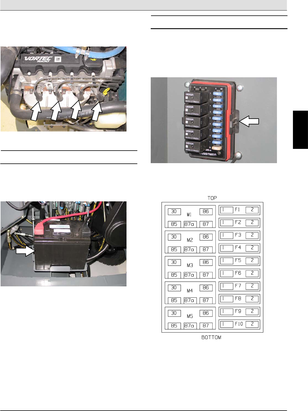
SPARK PLUGS (Gasoline/LPG)
Clean or replace, and set the gap of the spark plugs
after every 400 hours of operation. The proper spark
plug gap is 1 mm (0.042 in).
BATTERY
Clean and tighten the battery connections after the
first 50 hours of operation and after every 800 hours
after that. Do not remove the vent plugs from the
battery or add water to the battery.
FOR SAFETY: When servicing machine, avoid
contact with battery acid.
FUSES AND RELAYS
RELAY PANEL FUSES AND RELAYS
Remove the relay panel cover to access fuses and
relays. Always replace a fuse with a fuse of the same
amperage. Extra 15 Amp fuses are provided inside
the relay panel drawer on the relay panel.
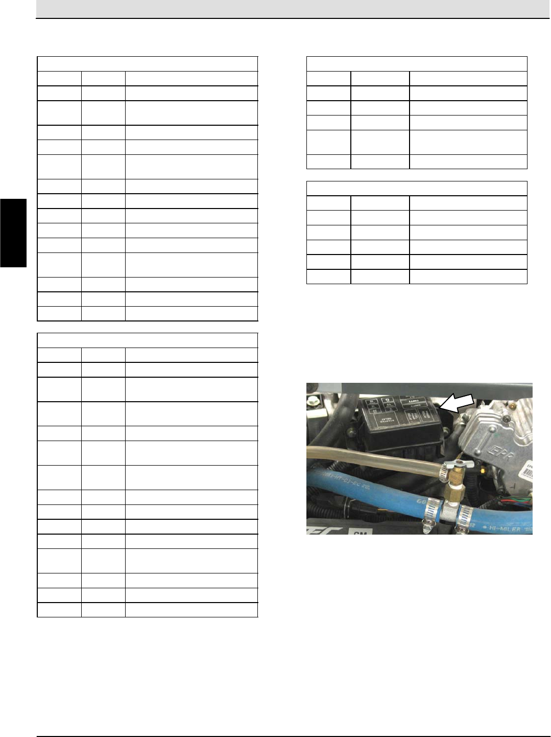
Refer to the diagram below for locations of the fuses
and relays on the relay panel.
M
Home
Find...
Go To..
Maintenance & Repair S30 SERVICE INFORMATION
S30 9004086 (4--08)
24
Refer to the tables below for the fuses and circuits
protected.
S30
Fuse Rating Circuit Protected
FU1 15 A Horn
FU2 15 A Key Switch, Engine,
Instrumentation
FU3 15 A Turn Signals, 4--Way Flashers
FU4 15 A Extra Fused, Switched B+
FU5 15 A Main Brush Valves, Side Brush
Valves
FU6 15 A Hopper Valves
FU7 15 A Lights, Backup Alarm
FU8 15 A Extra Fused B+
FU9 15 A Shaker, Vacuum Fan Valve
FU10 15 A Not Used
FU11 60 A Main Power Fuse, In Line, In Main
Harness
FU12 60 A Cab Power (Optional)
FU13 40 A Not Used
FU14 60 A Not Used
S30XP and S30X4
Fuse Rating Circuit Protected
FU1 15 A Horn
FU2 15 A Key Switch, Engine,
Instrumentation
FU3 15 A Turn Signals, 4--Way Flashers,
Shaker
FU4 15 A Control Board
FU5 15 A Main Brush Valves, Side Brush
Valves
FU6 15 A Hopper Valves, Vacuum Fan
Valves
FU7 15 A Lights, Backup Alarm
FU8 15 A Extra Fused B+
FU9 15 A Extra Switched, Fused B+
FU10 15 A Not Used
FU11 60 A Main Power Fuse, In Line, In Main
Harness
FU12 60 A Cab Power (Optional)
FU13 40 A Not Used
FU14 60 A Not Used
NOTE: Always replace a fuse with a fuse of the same
amperage.
Refer to the tables below for the relays and circuits
controlled.
S30
Relay Rating Circuit Controlled
M1 12 VDC, 40 A Horn
M2 12 VDC, 40 A Auxiliary 1
M3 12 VDC, 40 A Shaker
M4 12 VDC, 40 A Main Brush Valves, Side
Brush Valves
M5 12 VDC, 40 A Auxiliary 2
S30XP and S30X4
Relay Rating Circuit Controlled
M1 12 VDC, 40 A Horn
M2 12 VDC, 40 A Auxiliary 1
M3 12 VDC, 40 A Shaker
M4 12 VDC, 40 A Not Used
M5 12 VDC, 40 A Auxiliary 2
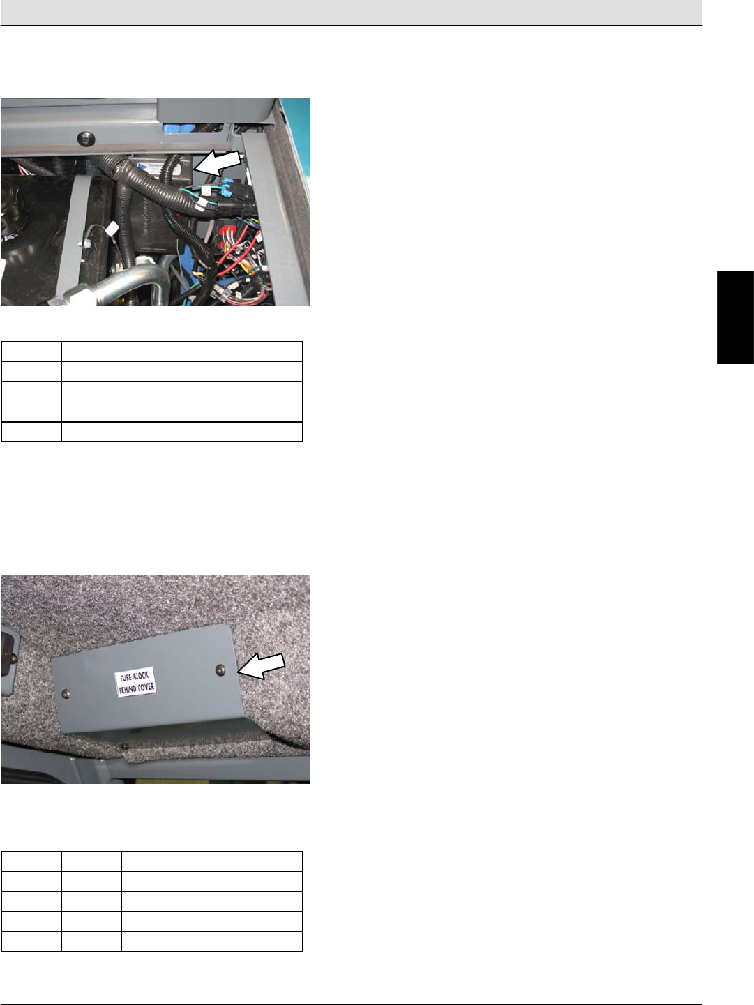
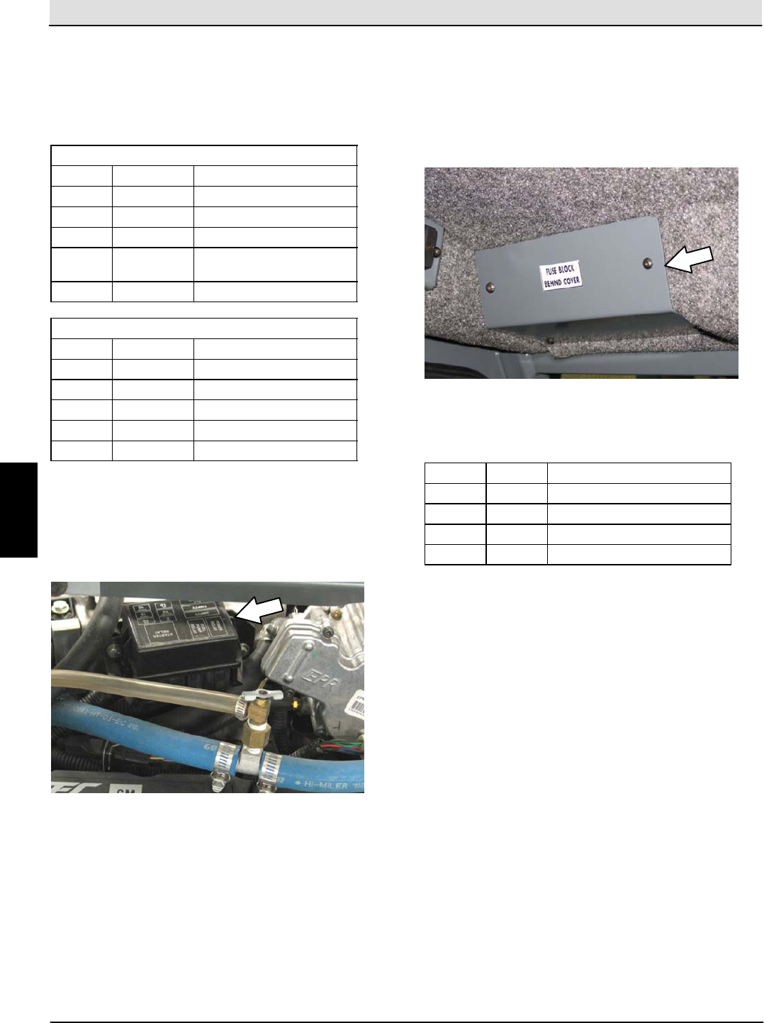
ENGINE HARNESS FUSES AND RELAYS
(Gasoline/LPG)
The engine harness fuses and relays are located in
the fuse box inside the engine compartment. Refer to
the fuse box cover for locations of engine harness
fuses and relays.
NOTE: Always replace a fuse with a fuse of the same
amperage.
M
Home
Find...
Go To..
S30 SERVICE INFORMATION Maintenance & Repair
S30 9004086 (4--08) 25
ENGINE HARNESS RELAYS (Diesel)
The engine harness relays are located inside the
engine compartment.
Relay Rating Circuit Controlled
M9 12 VDC, 40 A Starter Solenoid
M10 12 VDC, 40 A Anti--Restart
M11 12 VDC, 40 A Fuel Pump
M12 12 VDC, 40 A Glow Plug
NOTE: Always replace a fuse with a fuse of the same
amperage.
CAB FUSES (CAB OPTION)
The cab fuses are located in the fuse box inside the
cab. Remove the fuse cover to access the fuses.
Refer to the table below for the fuses and circuits
controlled.
Fuse Rating Circuit Protected
FU1 5A Lights
FU2 5A Wiper
FU3 20 A Air Conditioner
FU4 2A Heat
NOTE: Always replace a fuse with a fuse of the same
amperage.
M
Home
Find...
Go To..
Maintenance & Repair S30 SERVICE INFORMATION
S30 9004086 (4--08)
26
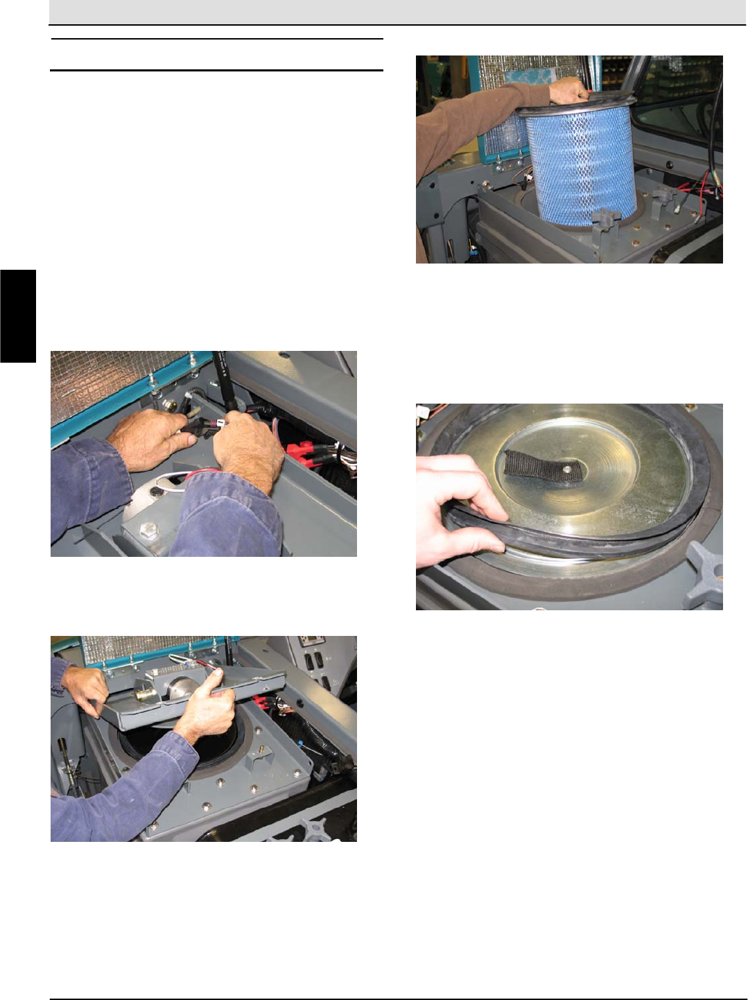
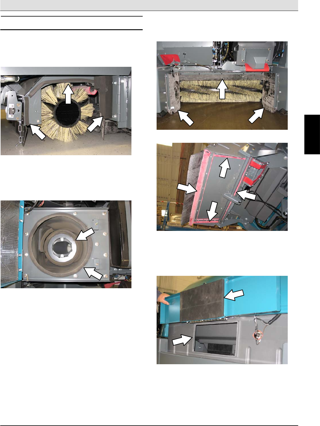
REMOVING AND INSPECTING THE DUST FILTER
Shake the dust filter at the end of every shift and
before removing the filter from the machine. Inspect
and clean the filter after every 100 hours of operation.
Replace damaged dust filters.
NOTE: Clean the filter more often if used in extremely
dusty conditions.
FOR SAFETY: Before leaving or servicing
machine, stop on level surface, set parking brake,
and turn off machine.
1. Open the top cover and side shroud.
2. Disconnect the filter shaker wire from the
harness.
3. Remove the filter shaker assembly from the filter
housing.
4. Remove the dust filter from the filter housing.
5. Clean or discard the dust filter element. Refer to
CLEANING THE DUST FILTER.
6. Insert the dust filter into the filter housing and
reinstall the removed parts. Be sure the seal is
installed as shown below.
7. Close the side shroud and top cover.
M
Home
Find...
Go To..
S30 SERVICE INFORMATION Maintenance & Repair
S30 9004086 (4--08) 27
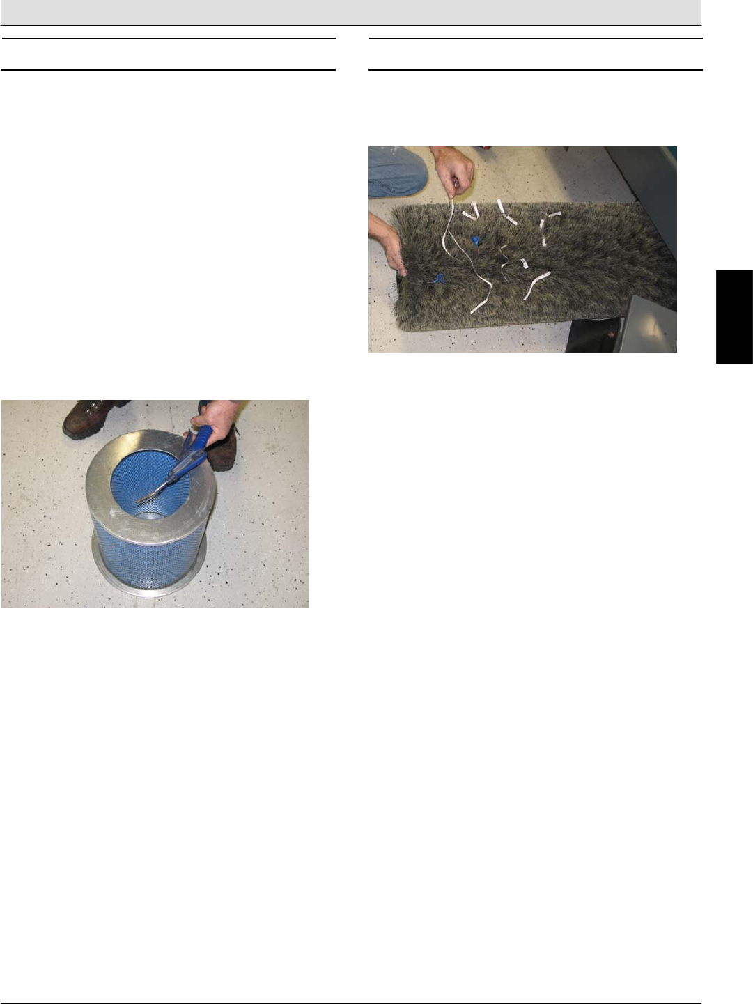
CLEANING THE DUST FILTER
Use one of the following methods to clean the dust
filter:
SHAKING--Press the filter shaker switch.
TAPPING--Tap the filter gently on a flat surface. Do
not damage the edges of the filter. The filter will not
seal properly if the edges of the filter are damaged.
AIR--Always wear eye protection when using
compressed air. Blow air through the center of the
filter and out toward the exterior. Never use more than
550 kPa (80 psi) of air pressure with a nozzle no
smaller than 3 mm (0.13 in) and never hold the nozzle
closer than 50 mm (2 in) to the filter.
FOR SAFETY: When servicing machine, wear eye
and ear protection when using pressurized air or
water.
MAIN BRUSH
Check the brush daily for wear or damage. Remove
any string or wire tangled on the main brush, main
brush drive hub, or main brush idler hub.
Check the main brush pattern and rotate the brush
end-for-end after every 50 hours of operation, for
maximum brush life and best sweeping performance.
Refer to REPLACING OR ROTATING THE MAIN
BRUSH.
Replace the main brush when the remaining bristles
measure 25 mm (1.0 in) in length.
M
Home
Find...
Go To..
Maintenance & Repair S30 SERVICE INFORMATION
S30 9004086 (4--08)
28
REPLACING OR ROTATING THE MAIN BRUSH
1. Raise the brush head.
FOR SAFETY: Before leaving or servicing
machine, stop on level surface, set parking brake,
and turn off machine.
2. Open the right side main brush access door.
3. Unlatch and remove the brush idler plate.
4. Pull the main brush from the main brush
compartment.
5. Replace or rotate the main brush end--for--end.
6. Slide the brush into the brush compartment and
all the way onto the drive plug.
7. Reinstall the brush idler plate.
8. Close the right side main brush access door.
9. Check and adjust the brush pattern if needed.
Refer to CHECKING THE MAIN BRUSH
PATTERN.
M
Home
Find...
Go To..
S30 SERVICE INFORMATION Maintenance & Repair
S30 9004086 (4--08) 29
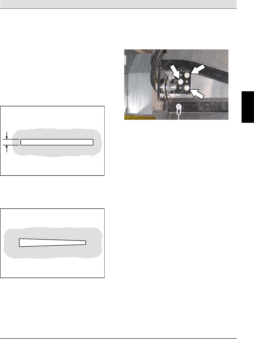
CHECKING THE MAIN BRUSH PATTERN
1. Apply chalk, or a similar marking material, to a
smooth and level section of the floor.
NOTE: If chalk or other material is not available, allow
the brush to spin on the floor for two minutes. A polish
mark will remain on the floor.
2. Lower the main brush onto the chalked area and
hold it there for 15 to 20 seconds without moving
the machine.
3. Raise the brush and drive the machine from the
chalked area. The brush pattern should be 50 to
65 mm (2.0 to 2.5 in) across the entire length of
the brush. Refer to ADJUSTING THE MAIN
BRUSH WIDTH.
0
0
5
8
2
4. If the brush pattern is tapered, see ADJUSTING
THE MAIN BRUSH TAPER section of this
manual.
0
0
6
0
1
ADJUSTING THE MAIN BRUSH TAPER
FOR SAFETY: Before leaving or servicing
machine, stop on level surface, set parking brake,
and turn off machine.
1. Loosen the shaft bearing bracket mounting bolts.
2. Move the bracket up or down in the slots and
tighten the mounting bolts.
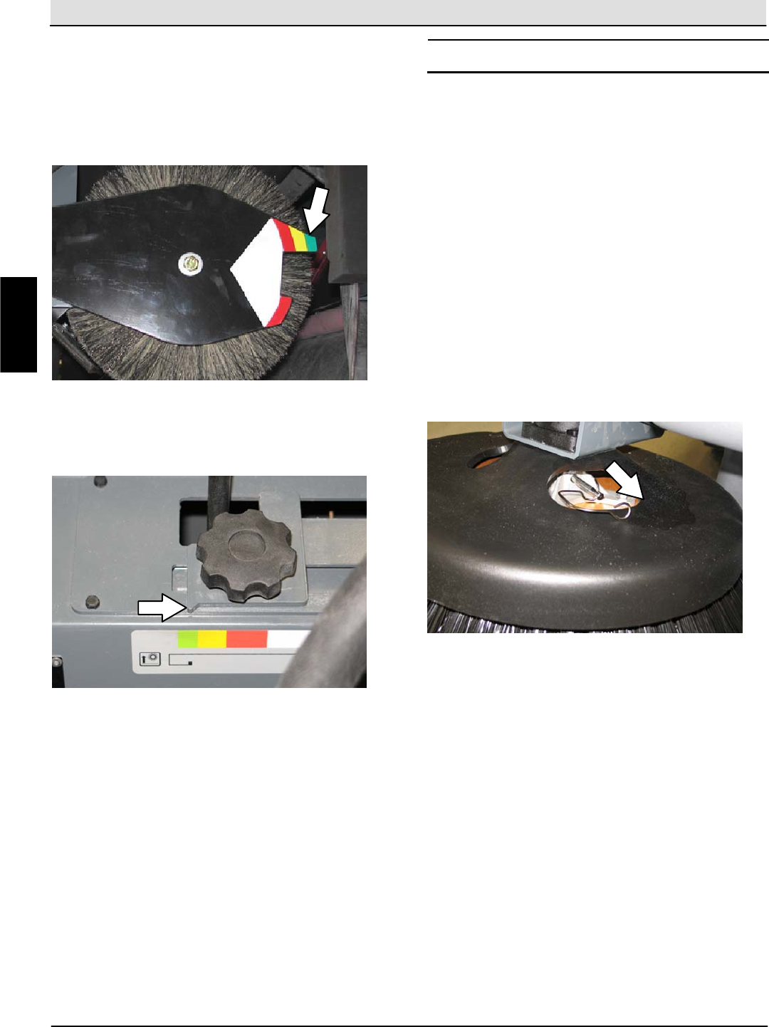
3. Check the main brush pattern and readjust as
necessary. Set the main brush adjustment knob
pointer to the same color band as the brush idler
plate.
M
Home
Find...
Go To..
Maintenance & Repair S30 SERVICE INFORMATION
S30 9004086 (4--08)
30
ADJUSTING THE MAIN BRUSH WIDTH
FOR SAFETY: Before leaving or servicing
machine, stop on level surface, set parking brake,
and turn off machine.
1. Compare the length of the main brush bristles
with the color band on the brush idler plate.
2. Loosen the main brush adjustment knob and slide
the pointer so it matches the color band on the
brush idler plate. Retighten the knob.
3. Recheck the pattern. Readjust if necessary.
SIDE BRUSH
Check the side brush daily for wear or damage.
Remove any tangled string or wire from the side
brush or side brush drive hub.
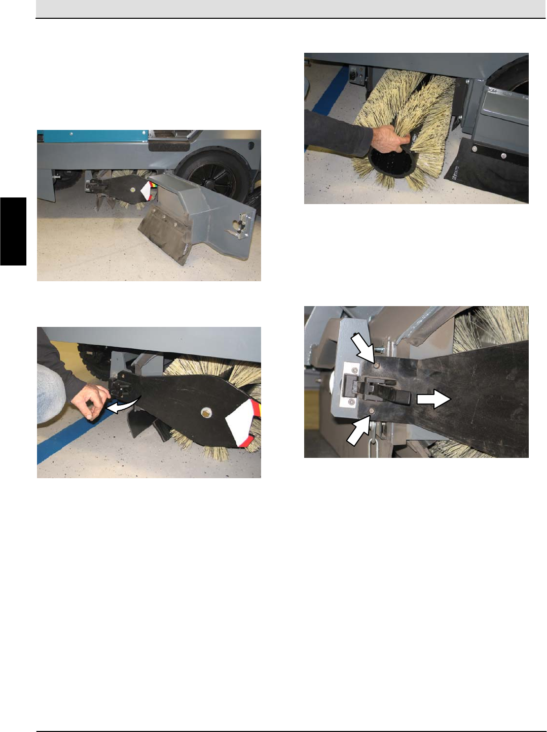
REPLACING THE SIDE BRUSH
Replace the side brush when it no longer cleans
effectively or when the remaining bristles are 64 mm
(2.5 in) or less in length. The side brush may be
changed sooner if sweeping light litter. The bristles
may be worn shorter if sweeping heavy debris.
1. Raise the side brush.
FOR SAFETY: Before leaving or servicing
machine, stop on level surface, set parking brake,
and turn off machine.
2. Remove the side brush retaining pin and then
remove the side brush.
NOTE: Remove the drive hub and put it on the new
brush if one is not installed.
3. Slide the new side brush onto the side brush drive
shaft and reinstall the retaining pin.
4. Adjust the side brush pattern. Refer to
ADJUSTING THE SIDE BRUSH PATTERN.
M
Home
Find...
Go To..
S30 SERVICE INFORMATION Maintenance & Repair
S30 9004086 (4--08) 31
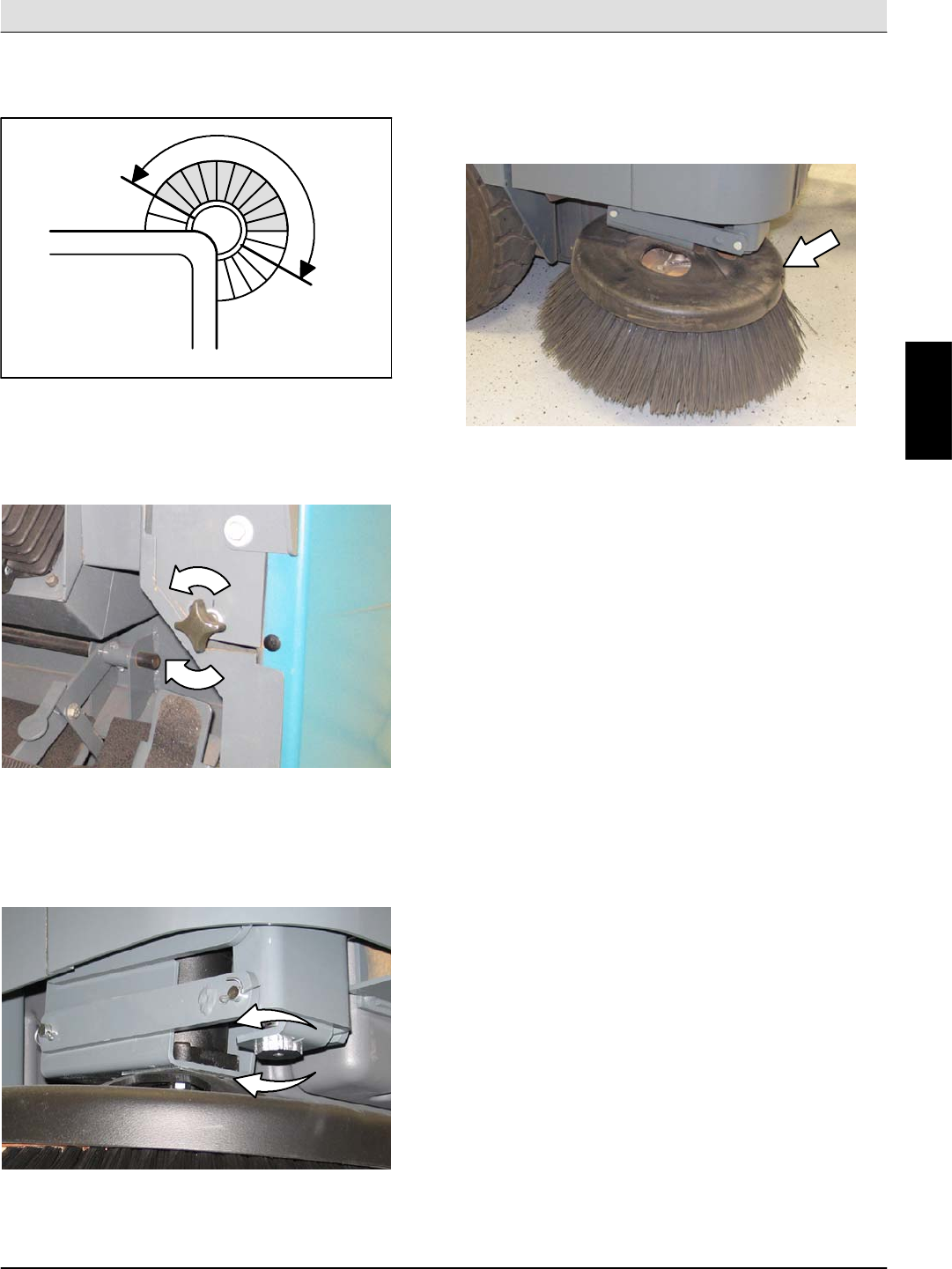
ADJUSTING THE SIDE BRUSH PATTERN
The side brush bristles should touch the floor between
10 o’clock and 4 o’clock when the brush is in motion.
350327
S30: Turn the side brush adjustment knob
counterclockwise to increase the brush pattern and
clockwise to decrease the brush pattern.
S30XP and S30X4: Tighten the side brush
adjustment knob into the side brush bracket to
increase the brush pattern and loosen the knob to
decrease the brush pattern.
ROTATING AND REPLACING THE SIDE BRUSH
GUARD
Rotate the side brush guard 90_every 200 hours of
operation. Replace the brush guard after all four sides
have been used.
M
Home
Find...
Go To..
Maintenance & Repair S30 SERVICE INFORMATION
S30 9004086 (4--08)
32
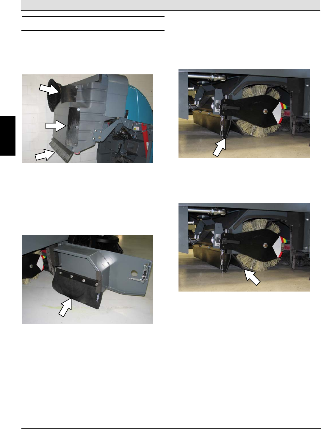
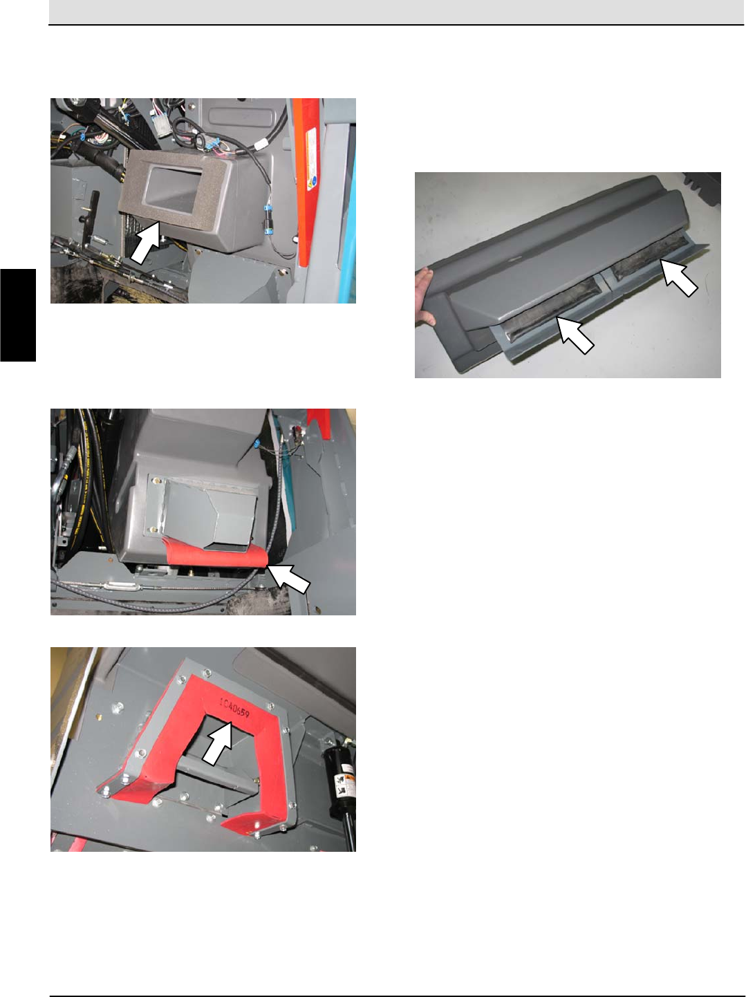
SKIRTS AND FLAPS
HOPPER SKIRTS
Check the hopper skirts for wear or damage daily.
Replace the hopper skirts when they no longer touch
the floor.
BRUSH DOOR SKIRTS
NOTE: Be sure the rear tire is properly inflated before
checking skirt clearances.
The brush door skirts should clear the floor by
3 to 6 mm (0.12 to 0.25 in). Check the skirts for wear
or damage and adjustment daily.
NOTE: The brush door skirts have slotted holes to
allow for a ground clearance adjustment. The door
must be closed for proper adjustment.
REAR SKIRT
NOTE: Be sure the rear tire is properly inflated before
checking skirt clearances.
The rear brush skirt should clear the floor by
3 to 6 mm (0.12 to 0.25 in). Check the skirt for wear
or damage and adjustment daily.
RECIRCULATION FLAP
The recirculation flap is self-adjusting. Check the flap
for wear or damage daily.
M
Home
Find...
Go To..
S30 SERVICE INFORMATION Maintenance & Repair
S30 9004086 (4--08) 33
SEALS
BRUSH DOOR SEALS
Check the brush door seals for wear or damage every
100 hours of operation.
DUST FILTER SEALS
Check the dust filter seals for wear or damage every
100 hours of operation.
HOPPER SEALS
Check the hopper door seals for wear or damage
every 100 hours of operation.
HOPPER INSPECTION DOOR SEALS
Check the hopper inspection door seal for wear or
damage every 100 hours of operation.
M
Home
Find...
Go To..
Maintenance & Repair S30 SERVICE INFORMATION
S30 9004086 (4--08)
34
FILTER CHAMBER INLET SEAL
Check the filter chamber inlet seal for wear or
damage every 100 hours of operation.
DUST RETURN SEALS
Check the dust return seals for wear or damage every
100 hours of operation.
VACUUM WAND DOOR SEALS (OPTION)
Check the vacuum wand door seal for wear or
damage every 100 hours of operation.
CYCLONIC PRE--FILTER SEALS
Check the cyclonic pre--filter seals for wear or
damage every 100 hours of operation.
M
Home
Find...
Go To..
S30 SERVICE INFORMATION Maintenance & Repair
S30 9004086 (4--08) 35
BRAKES AND TIRES
BRAKES
Check the brake adjustment after every 200 hours of
operation.
PARKING BRAKE
Check the parking brake adjustment after every 200
hours of operation.
TIRES
The standard front tires are solid. The standard rear
tire is pneumatic.
Check the rear tire pressure every 100 hours of
operation. The proper air pressure is
790 + 35kPa(115+5 psi).
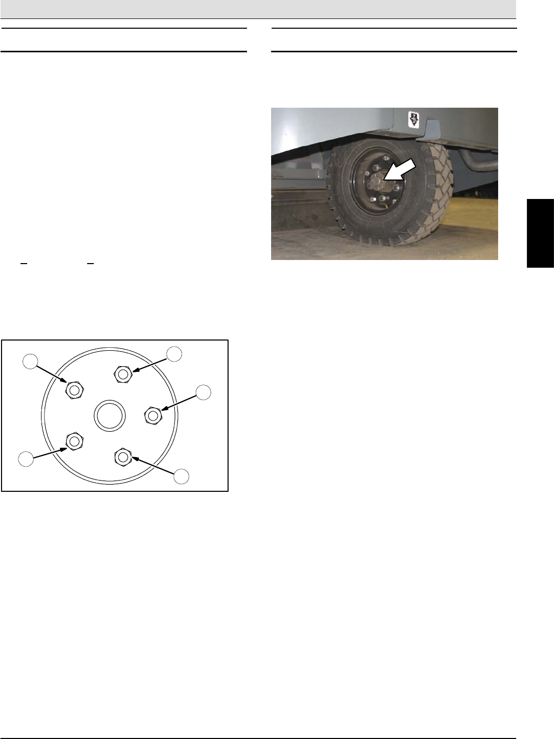
REAR WHEEL
Torque the rear wheel nuts twice in the pattern shown
to 122 to 149 Nm (90 to 110 ft lb) after the first 50
hours of operation, and then after every 800 hours.
2
3
4
1
5
PROPELLING MOTOR
Torque the shaft nut to 508 Nm (375 ft lb) lubricated,
644 Nm (475 ft lb) dry, after every 800 hours of
operation.
M
Home
Find...
Go To..
Maintenance & Repair S30 SERVICE INFORMATION
S30 9004086 (4--08)
36
PUSHING, TOWING, AND TRANSPORTING THE
MACHINE
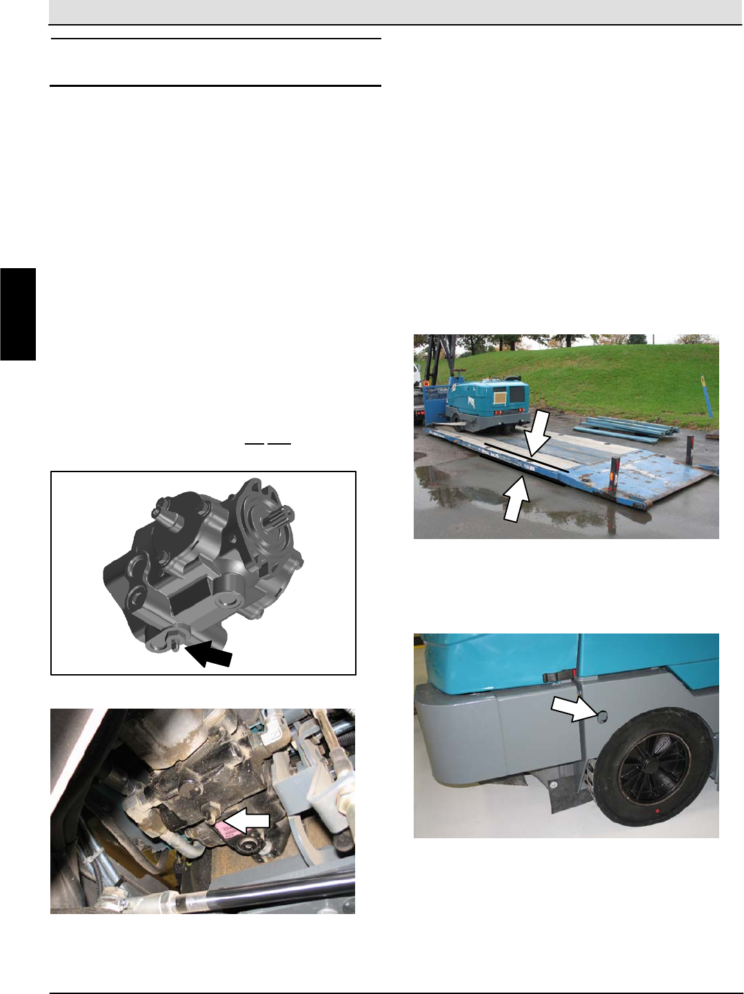
PUSHING OR TOWING THE MACHINE
If the machine becomes disabled, it can be pushed
from the front or rear, but only towed from the rear.
Use the bypass valve to prevent damaging the
hydraulic system when pushing or towing the
machine. This valve allows a disabled machine to be
moved for a very short distance and at a speed to not
exceed 1.6 kp/h (1 mph). The machine is NOT
intended to be pushed or towed a long distance or at
a high speed.
ATTENTION! Do not push or tow machine for a
long distance or damage may occur to the
propelling system.
Turn the bypass valve located on the bottom of the
propelling pump 90_(either direction) from the normal
position before pushing or towing the machine. Return
the bypass valve to the normal position when finished
pushing or towing the machine. Do Not use the
bypass valve during normal machine operation.
TRANSPORTING THE MACHINE
1. Raise the brushes. If necessary, slightly raise the
hopper for additional ramp clearance.
NOTE: Empty the hopper before transporting.
2. Position the front of the machine at the loading
edge of the truck or trailer.
FOR SAFETY: When loading machine onto truck
or trailer, use winch. Do not drive the machine
onto the truck or trailer unless the loading
surface is horizontal AND is 380 mm (15 in) or
less from the ground.
3. If the loading surface is horizontal and 380 mm
(15 in) or less from the ground, drive the machine
onto the truck or trailer.
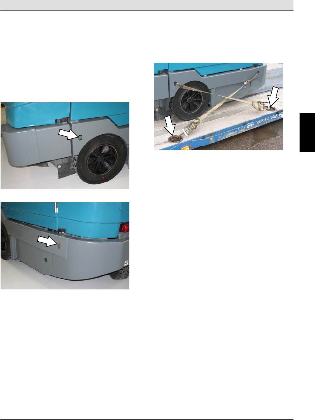
4. To winch the machine onto the truck or trailer,
attach the winching chains to the holes in the right
and left lower corners in front of the machine.
M
Home
Find...
Go To..
S30 SERVICE INFORMATION Maintenance & Repair
S30 9004086 (4--08) 37
5. Position the machine as close to the front of the
trailer or truck as possible.
6. Set the parking brake and place a block behind
each wheel to prevent the machine from rolling.
7. Lower the brushes and hopper (if hopper was
raised).
8. Connect the tie--down straps to the holes in the
right and left lower corners in front of the machine
and the holes in the rear jacking brackets behind
the rear tires.
9. Route the tie--downs to the opposite ends of the
machine and hook them to the brackets on the
floor of the trailer or truck. Tighten the tie--down
straps.
NOTE: It may be necessary to install tie-down
brackets to the floor of the trailer or truck.
FOR SAFETY: When unloading machine off truck
or trailer, use winch. Do not drive the machine off
the truck or trailer unless the loading surface is
horizontal AND 380 mm
(15 in) or less from the ground.
10. If the loading surface is horizontal AND is 380
mm (15 in) or less from the ground, drive the
machine off the truck or trailer.
M
Home
Find...
Go To..
Maintenance & Repair S30 SERVICE INFORMATION
S30 9004086 (4--08)
38
MACHINE JACKING
Empty the hopper before jacking up the machine.
Jack up the machine at the designated locations. Use
a hoist or jack capable of supporting the weight of the
machine. Use jack stands to support the machine.
FOR SAFETY: Before leaving or servicing
machine, stop on level surface, set parking brake,
and turn off machine.
FOR SAFETY: When servicing machine, block
machine tires before jacking machine up. Use a
hoist or jack that will support the weight of the
machine. Jack machine up at designated
locations only. Support machine with jack stands.
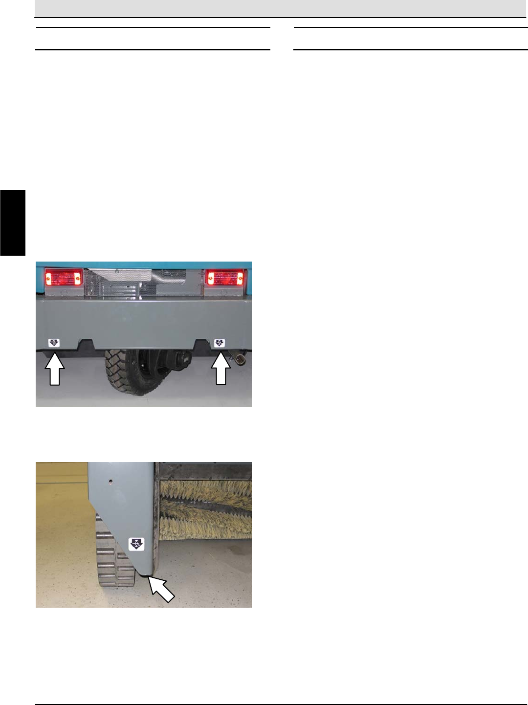
Rear jacking locations are located directly behind the
rear tire on each side of the machine.
Front jacking locations are located on the frame
directly in front of the front tire.
STORAGE INFORMATION
The following steps should be taken prior to storing
the machine for extended periods.
1. Park the machine in a cool, dry area. Do not
expose the machine to rain or snow. Store
indoors.
2. Remove the battery, or charge battery every three
months.
M
Home
Find...
Go To..

S30 SERVICE INFORMATION Electrical Troubleshooting
S30 9004086 (4--08) 39
ELECTRICAL
Troubleshooting Information
BEFORE CONDUCTING TESTS:
* Read and Follow ALL Safety Warnings and Precautions as mentioned
at the beginning of this manual
* Always use an ESD (Electrostatic Discharge) strap when working near
the Control Board
* Be cautious when working near Control Board -- Battery voltage is
always present, even with Key OFF
* Always unhook Battery when removing or replacing components
DURING TESTS:
* Call Technical Services if Diagnostic Time Exceeds One Hour With
Unknown Cause or Course of Action
NOTE: Troubleshooting charts may be shown with optional equipment. The optional equipment
may not be specified in these charts. Some machines may not be equipped with all components
shown.
E
Home
Find...
Go To..
Electrical Troubleshooting S30 SERVICE INFORMATION
S30 9004086 (4--08)
40
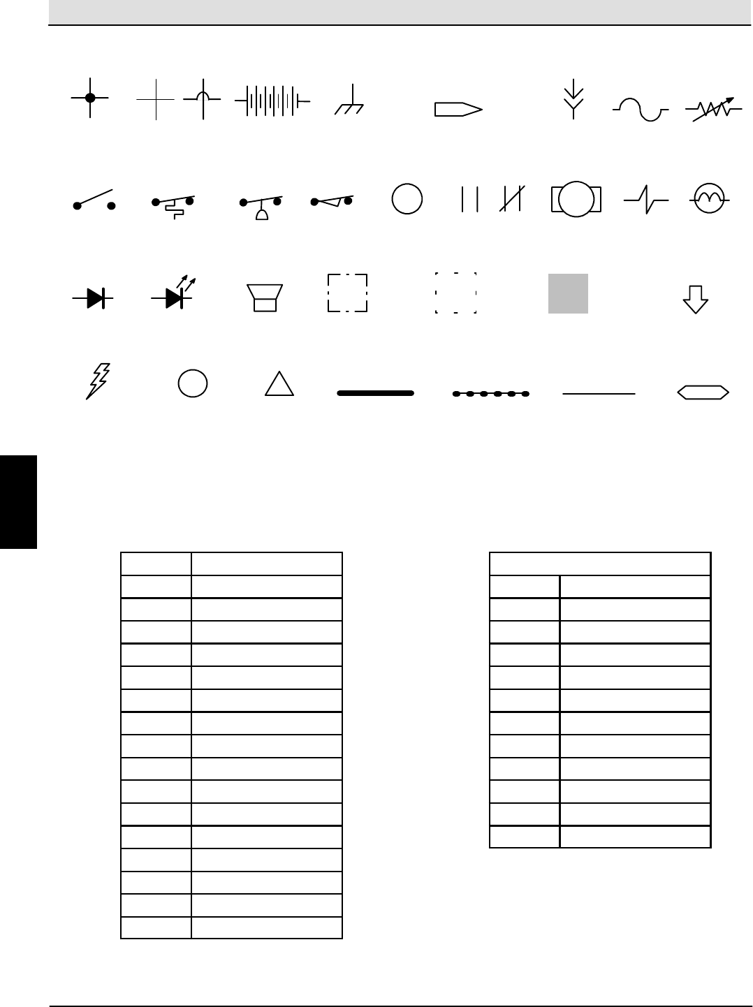
Electrical Symbols & Abbreviations
6/BLU
i
WIRES
CONNECTED
WIRES NOT
CONNECTED
PLUG--IN
CONNECTION
BATTERY
ON--OFF
SWITCH
TEMPERATURE
SWITCH
RELAY OR
SOLENOID
COIL
MOTOR
OPEN
RELAY
CONTACTS
ASSEMBLY COMPONENT IN
POSITION OTHER
THAN NORMAL
ACTIVATED
COMPONENT
MOVEMENT FROM
NORMAL POSITION
ENERGIZED
COMPONENT
INFORMATION BATTERY
POSITIVE
BATTERY
NEGATIVE
NON--ACTIVE
WIRE
WIRE NUMBER
& COLOR
SOLENOID
VALVE
CLOSED
PRESSURE
SWITCH
LAMP
LIMIT
SWITCH
CHASSIS
GROUND
CONNECTION TO OR
FROM ANOTHER POINT
SENDING
UNIT
FUSE
!
WARNING
DIODE LED (LIGHT
EMITTING DIODE)
HORN OR
ALARM
ABBREVIATIONS
AAmps
ACT Actuator
B+ Battery Positive
CKT Circuit
DDiode
FFuse
GND Ground
LP Lamp
MRelay Coil
MTR Motor
NC Normally Closed
NO Normally Open
PM Permanent Magnet
SorSW Switch
SV Solenoid Valve
TMR Timer
VDC Volts, Direct Current
Wire Colors
BLK Black
BLU Blue
BRN Brown
GRN Green
GRY Gray
ORA Orange
PNK Pink
PUR Purple
RED Red
TAN Tan
WHT White
YEL Yellow
E
Home
Find...
Go To..
S30 SERVICE INFORMATION Electrical Troubleshooting
S30 9004086 (4--08) 41
Fuses and Relays (S30,S30XP,S30X4)
(page 1 of 2)
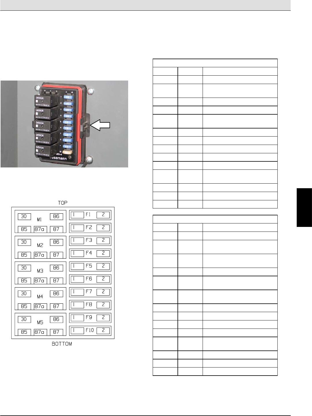
RELAY PANEL FUSES AND RELAYS
Remove the relay panel cover to access fuses and
relays. Always replace a fuse with a fuse of the same
amperage. Extra 15 Amp fuses are provided inside
the relay panel drawer on the relay panel.
Refer to the diagram below for locations of the fuses
and relays on the relay panel.
Refer to the tables below for the fuses and circuits
protected.
S30
Fuse Rating Circuit Protected
FU1 15 A Horn
FU2 15 A Key Switch, Engine,
Instrumentation
FU3 15 A Turn Signals, 4--Way Flashers
FU4 15 A Extra Fused, Switched B+
FU5 15 A Main Brush Valves, Side Brush
Valves
FU6 15 A Hopper Valves
FU7 15 A Lights, Backup Alarm
FU8 15 A Extra Fused B+
FU9 15 A Shaker, Vacuum Fan Valve
FU10 15 A Not Used
FU11 60 A Main Power Fuse, In Line, In Main
Harness
FU12 60 A Cab Power (Optional)
FU13 40 A Not Used
FU14 60 A Not Used
S30 XP and X4
Fuse Rating Circuit Protected
FU1 15 A Horn
FU2 15 A Key Switch, Engine,
Instrumentation
FU3 15 A Turn Signals, 4--Way Flashers,
Shaker
FU4 15 A Control Board
FU5 15 A Main Brush Valves, Side Brush
Valves
FU6 15 A Hopper Valves, Vacuum Fan
Valves
FU7 15 A Lights, Backup Alarm
FU8 15 A Extra Fused B+
FU9 15 A Extra Switched, Fused B+
FU10 15 A Not Used
FU11 60 A Main Power Fuse, In Line, In Main
Harness
FU12 60 A Cab Power (Optional)
FU13 40 A Not Used
FU14 60 A Not Used
NOTE: Always replace a fuse with a fuse of the same
amperage.
E
Home
Find...
Go To..
Electrical Troubleshooting S30 SERVICE INFORMATION
S30 9004086 (4--08)
42
Fuses and Relays (S30,S30XP,S30X4)
(page 2 of 2)
Refer to the tables below for the relays and circuits
controlled.
S30
Relay Rating Circuit Controlled
M1 12 VDC, 40 A Horn
M2 12 VDC, 40 A Auxiliary 1
M3 12 VDC, 40 A Shaker
M4 12 VDC, 40 A Main Brush Valves, Side
Brush Valves
M5 12 VDC, 40 A Auxiliary 2
S30 XP and X4
Relay Rating Circuit Controlled
M1 12 VDC, 40 A Horn
M2 12 VDC, 40 A Auxiliary 1
M3 12 VDC, 40 A Shaker
M4 12 VDC, 40 A Not Used
M5 12 VDC, 40 A Auxiliary 2
ENGINE HARNESS FUSES AND RELAYS
The engine harness fuses and relays are located in
the fuse box inside the engine compartment. Refer to
the fuse box cover for locations of engine harness
fuses and relays.
NOTE: Always replace a fuse with a fuse of the same
amperage.
CAB FUSES (CAB OPTION)
The cab fuses are located in the fuse box inside the
cab. Remove the fuse cover to access the fuses.
Refer to the table below for the fuses and circuits
controlled.
Fuse Rating Circuit Protected
FU1 5A Lights
FU2 5A Wiper
FU3 20 A Air Conditioner
FU4 2A Heat
NOTE: Always replace a fuse with a fuse of the same
amperage.
E
Home
Find...
Go To..
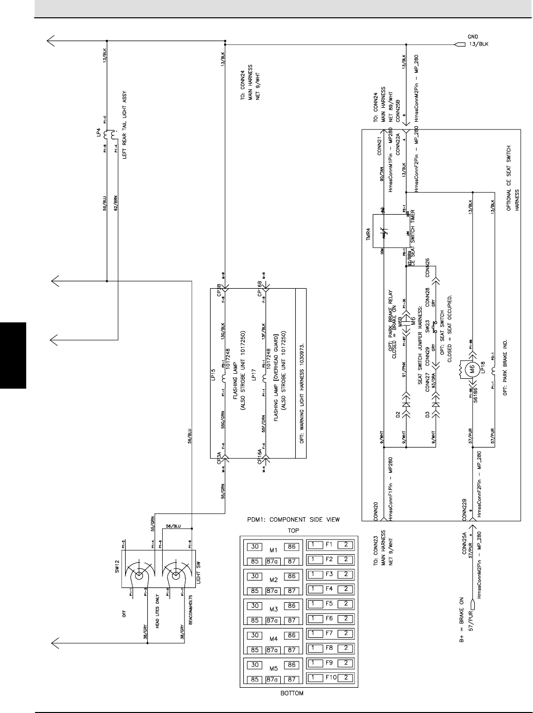
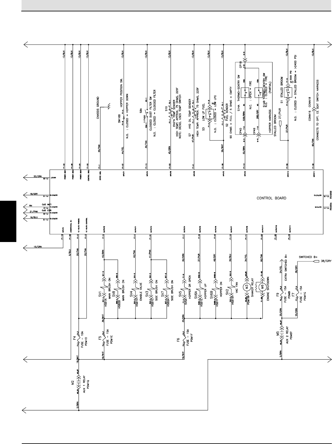
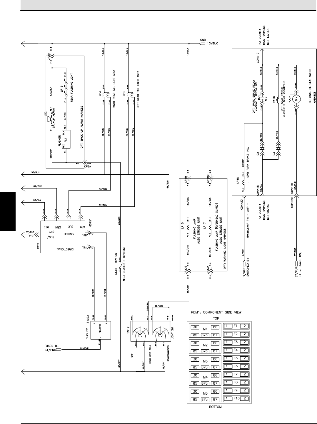
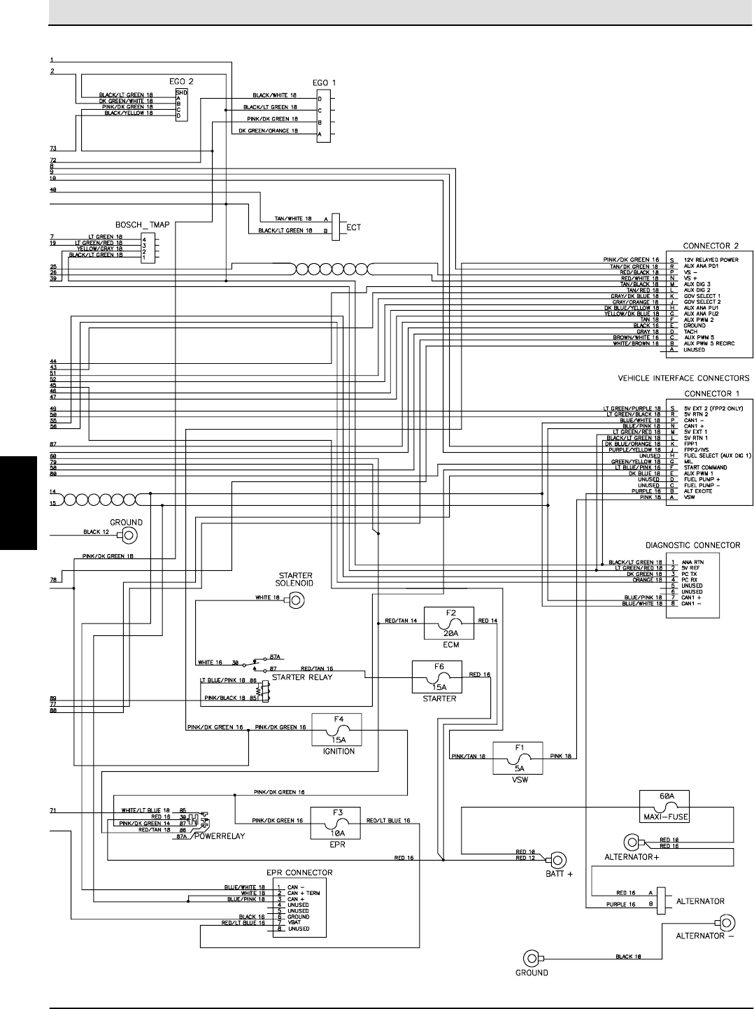
S30 SERVICE INFORMATION Electrical Troubleshooting
S30 9004086 (4--08) 43
S30 Electrical Schematic (1 of 4)
1029278-- 354728
E
Home
Find...
Go To..
Electrical Troubleshooting S30 SERVICE INFORMATION
S30 9004086 (4--08)
44
S30 Electrical Schematic (2 of 4)
1029278-- 354728
E
Home
Find...
Go To..
S30 SERVICE INFORMATION Electrical Troubleshooting
S30 9004086 (4--08) 45
S30 Electrical Schematic (3 of 4)
1029278-- 354728
E
Home
Find...
Go To..
Electrical Troubleshooting S30 SERVICE INFORMATION
S30 9004086 (4--08)
46
S30 Electrical Schematic (4 of 4)
1029278-- 354728
E
Home
Find...
Go To..
S30 SERVICE INFORMATION Electrical Troubleshooting
S30 9004086 (4--08) 47
S30XP / S30X4 Electrical Schematic (1 of 4)
1029279-- 354729
E
Home
Find...
Go To..
Electrical Troubleshooting S30 SERVICE INFORMATION
S30 9004086 (4--08)
48
S30XP / S30X4 Electrical Schematic (2 of 4)
1029279-- 354729
E
Home
Find...
Go To..
S30 SERVICE INFORMATION Electrical Troubleshooting
S30 9004086 (4--08) 49
S30XP / S30X4 Electrical Schematic (3 of 4)
1029279-- 354729
E
Home
Find...
Go To..
Electrical Troubleshooting S30 SERVICE INFORMATION
S30 9004086 (4--08)
50
S30XP / S30X4 Electrical Schematic (4 of 4)
1029279-- 354729
E
Home
Find...
Go To..
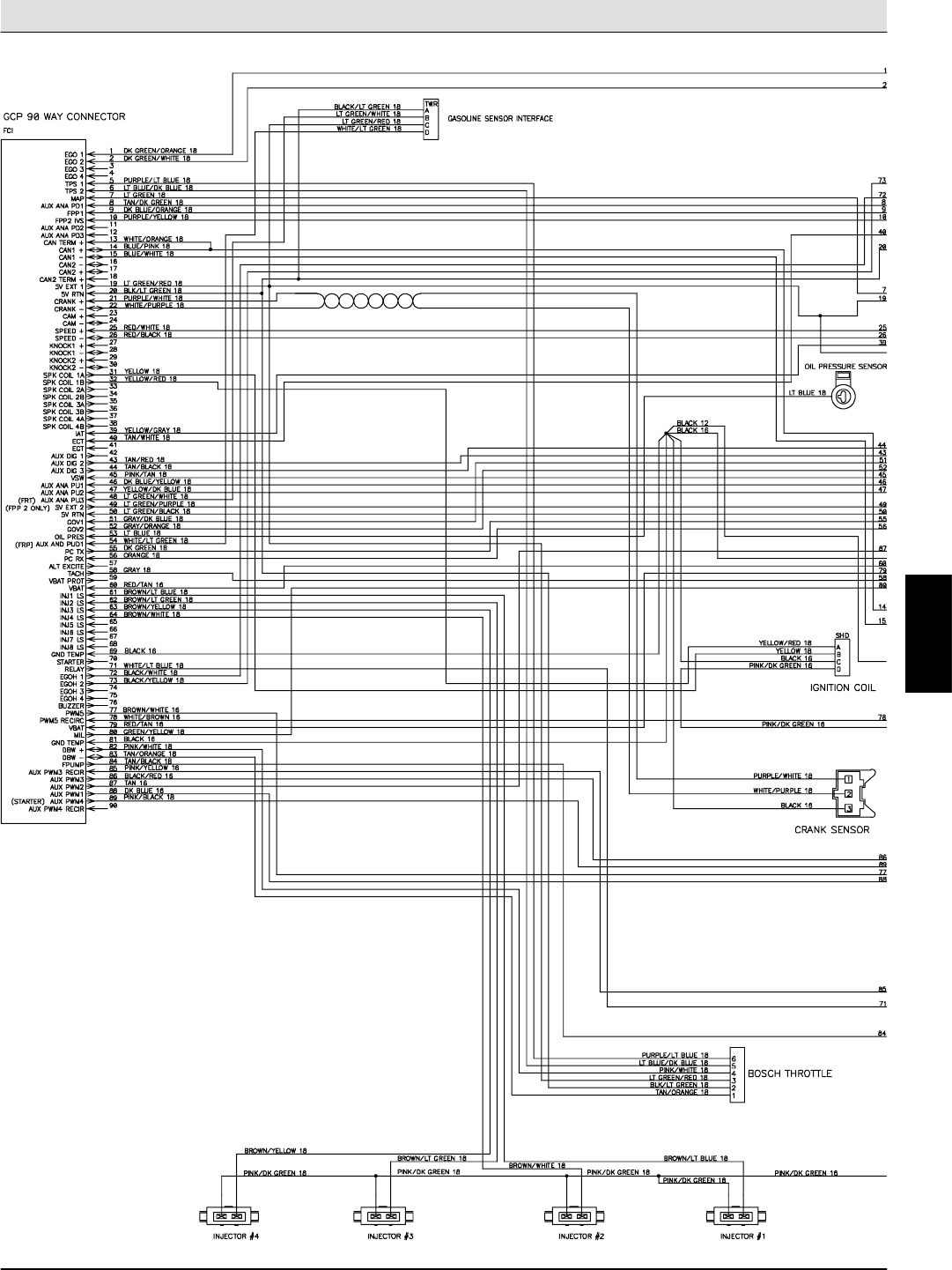
S30 SERVICE INFORMATION Electrical Troubleshooting
S30 9004086 (4--08) 51
Gasoline Engine Harness Electrical Schematic (1 of 2)
384997 -- 354495
E
Home
Find...
Go To..
Electrical Troubleshooting S30 SERVICE INFORMATION
S30 9004086 (4--08)
52
Gasoline Engine Harness Electrical Schematic (2 of 2)
384997 -- 354496
E
Home
Find...
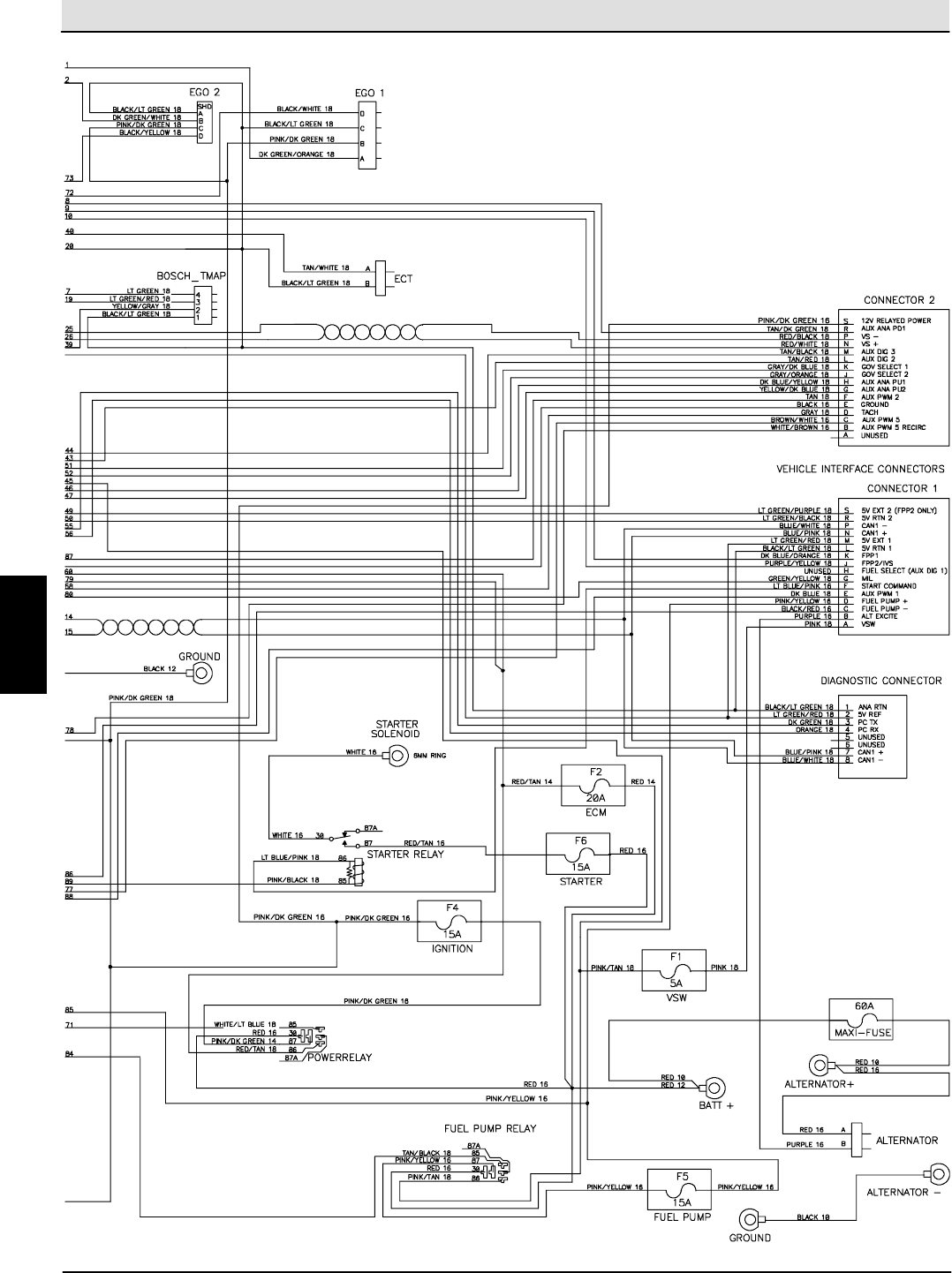
Go To..
S30 SERVICE INFORMATION Electrical Troubleshooting
S30 9004086 (4--08) 53
LPG Engine Harness Electrical Schematic (1 of 2)
384990 -- 354497
E
Home
Find...
Go To..
Electrical Troubleshooting S30 SERVICE INFORMATION
S30 9004086 (4--08)
54
LPG Engine Harness Electrical Schematic (2 of 2)
384990 -- 354498
E
Home
Find...
Go To..
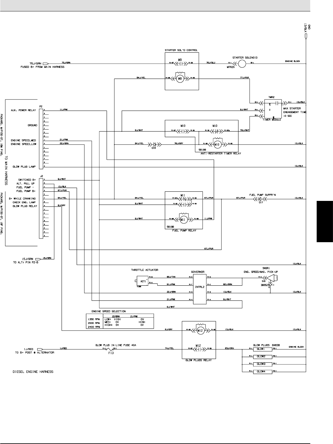
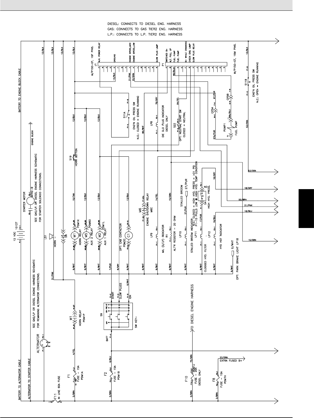
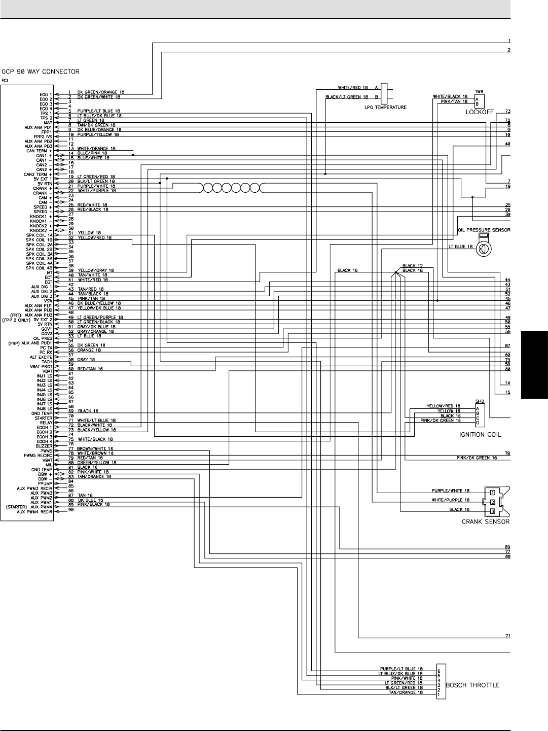
S30 SERVICE INFORMATION Electrical Troubleshooting
S30 9004086 (4--08) 55
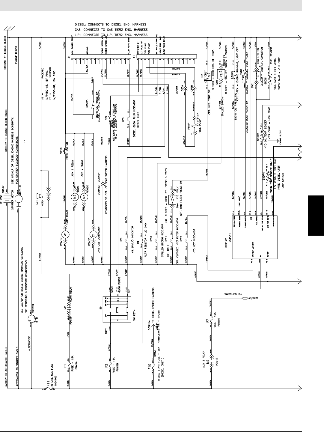
Diesel Engine Harness Electrical Schematic
1029278-- 354728
E
Home
Find...
Go To..
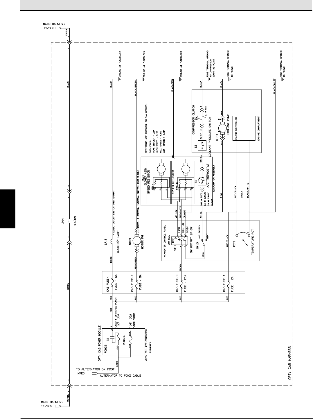
Electrical Troubleshooting S30 SERVICE INFORMATION
S30 9004086 (4--08)
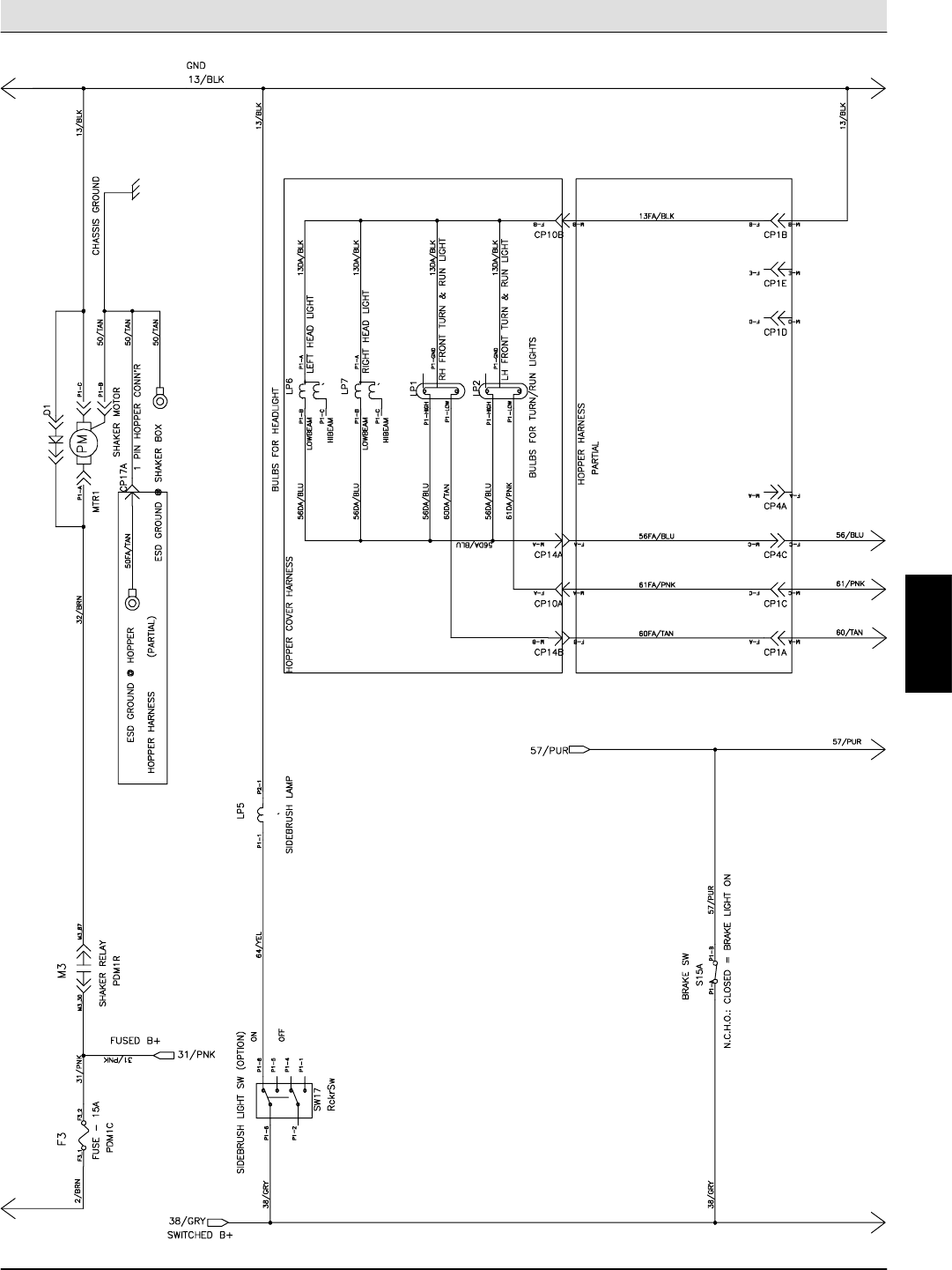
56
Cab Harness Electrical Schematic
1029278-- 354728
E
Home
Find...
Go To..
S30 SERVICE INFORMATION Electrical Troubleshooting
S30 9004086 (4--08) 57
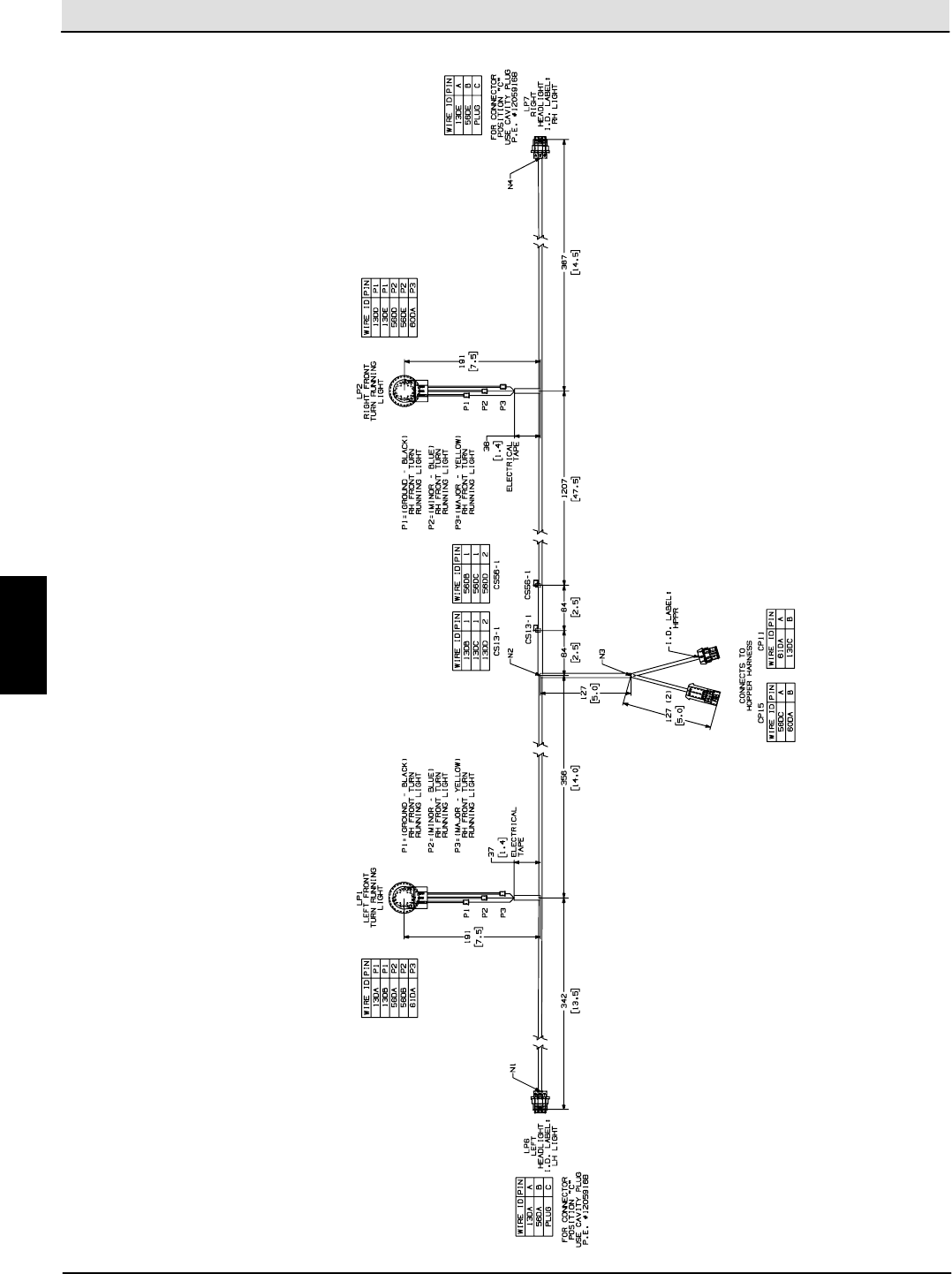
S30 Wire Harness Drawing (1 of 2)
E
Home
Find...
Go To..
Electrical Troubleshooting S30 SERVICE INFORMATION
S30 9004086 (4--08)
58
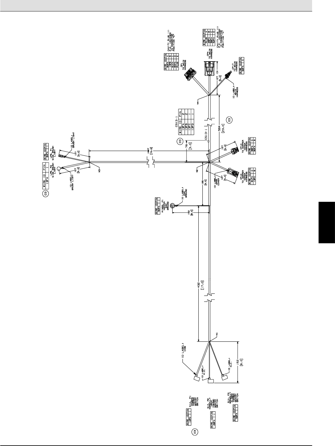
S30 Wire Harness Drawing (2 of 2)
E
Home
Find...
Go To..
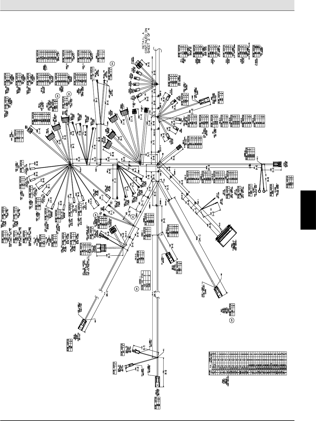
S30 SERVICE INFORMATION Electrical Troubleshooting
S30 9004086 (4--08) 59
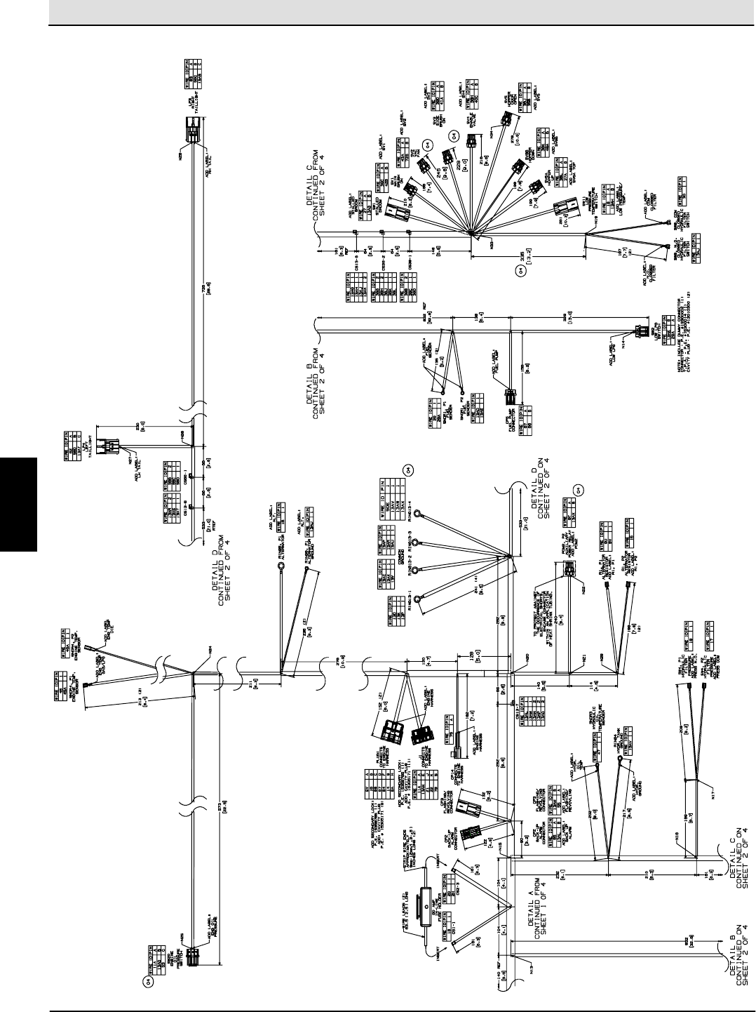
S30XP / S30X4 Wire Harness Drawing (1 of 3)
E
Home
Find...
Go To..
Electrical Troubleshooting S30 SERVICE INFORMATION
S30 9004086 (4--08)
60
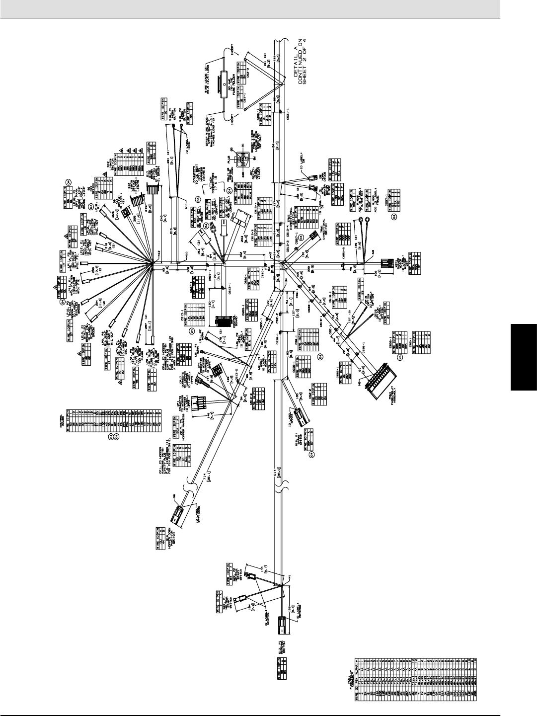
S30XP / S30X4 Wire Harness Drawing (2 of 3)
E
Home
Find...
Go To..
S30 SERVICE INFORMATION Electrical Troubleshooting
S30 9004086 (4--08) 61
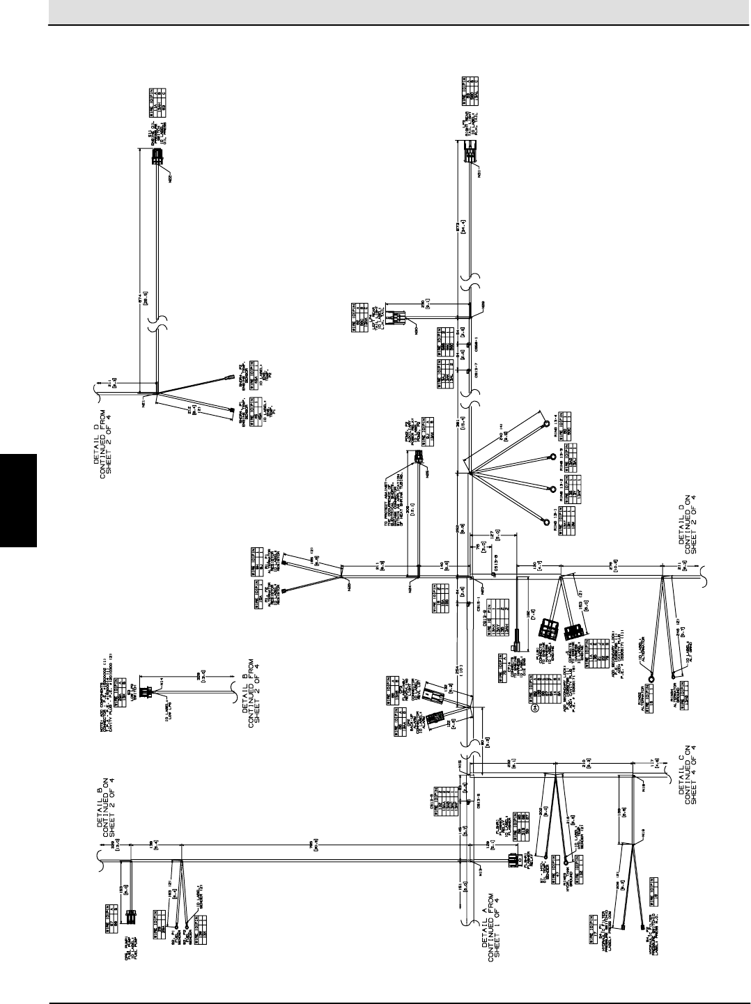
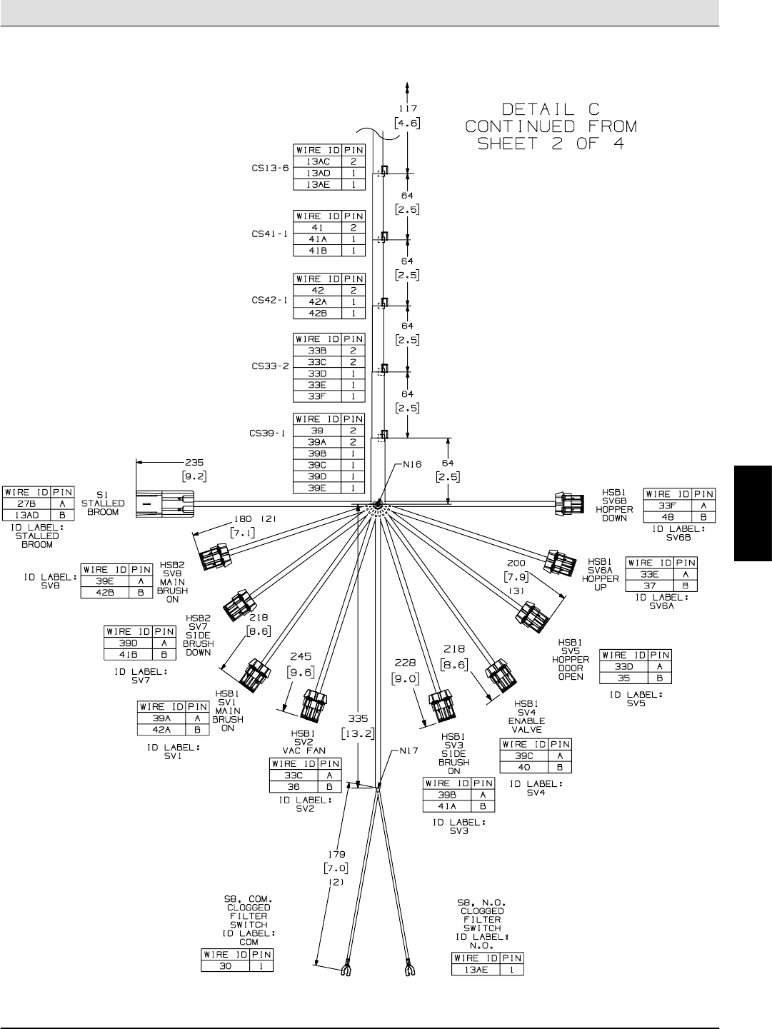
S30XP / S30X4 Wire Harness Drawing (3 of 3)
E
Home
Find...
Go To..
Electrical Troubleshooting S30 SERVICE INFORMATION
S30 9004086 (4--08)
62
All Machines Hopper Cover Wire Harness Drawing
E
Home
Find...
Go To..
S30 SERVICE INFORMATION Electrical Troubleshooting
S30 9004086 (4--08) 63
All Machines Hopper Wire Harness Drawing
E
Home
Find...
Go To..
Electrical Troubleshooting S30 SERVICE INFORMATION
S30 9004086 (4--08)
64
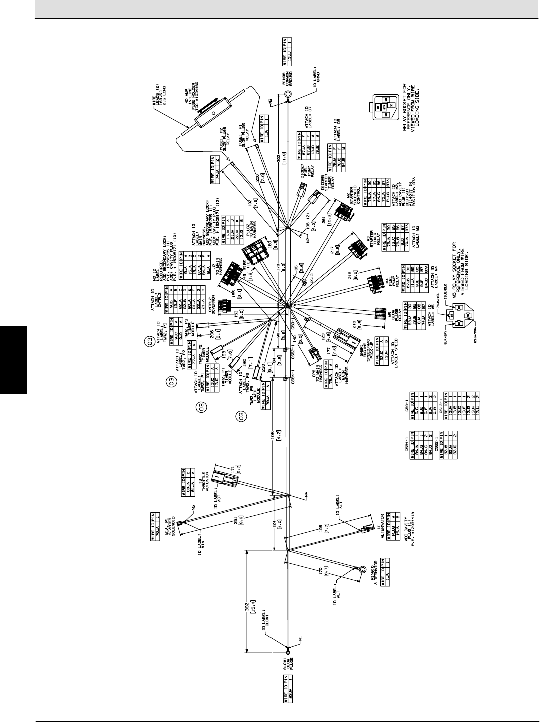
Diesel Engine Wire Harness Drawing
E
Home
Find...
Go To..
S30 SERVICE INFORMATION Electrical Troubleshooting
S30 9004086 (4--08) 65
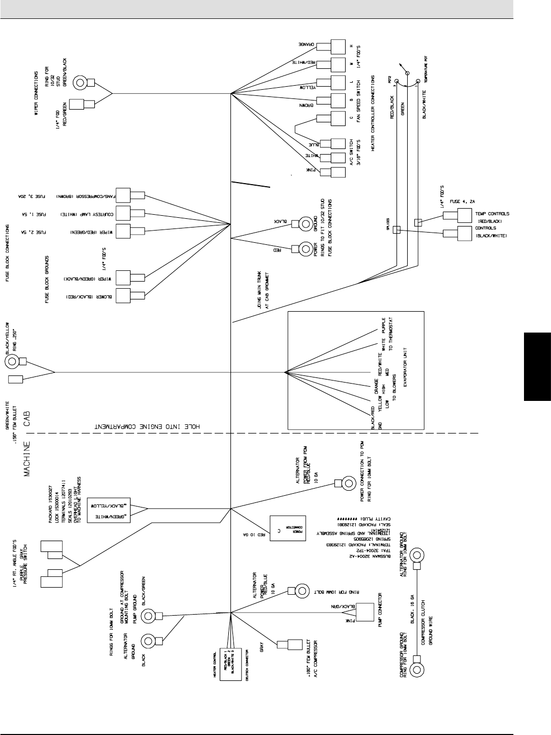
Cab Wire Harness Drawing
1
354761
E
Home
Find...
Go To..
Electrical Troubleshooting S30 SERVICE INFORMATION
S30 9004086 (4--08)
66
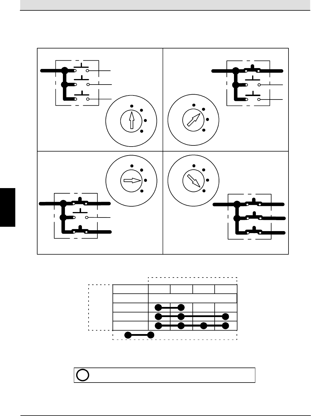
Key Switch Information (S30,S30XP,S30X4)
AB
C
D
OFF Position
AB
C
D
RUN Position
AB
C
D
Glow Plug Position
AB
C
D
START Position
OFF
RUN
GLOW
PLUG
START
KEY
SWITCH
OFF
RUN
GLOW
PLUG
START
KEY
SWITCH
OFF
RUN
GLOW
PLUG
START
KEY
SWITCH
OFF
RUN
GLOW
PLUG
START
KEY
SWITCH
(Diesel Only)
Spring loaded--Returns to RUN unless held Spring loaded--Returns to RUN unless held
START
OFF
RUN
Glow Plug
ABCD
No Connections
Key Switch pin terminal
Key Switch
position
““Indicates a common connection
iCommon connections in various switch positions should be less than 1
:
E
Home
Find...
Go To..
S30 SERVICE INFORMATION Electrical Troubleshooting
S30 9004086 (4--08) 67
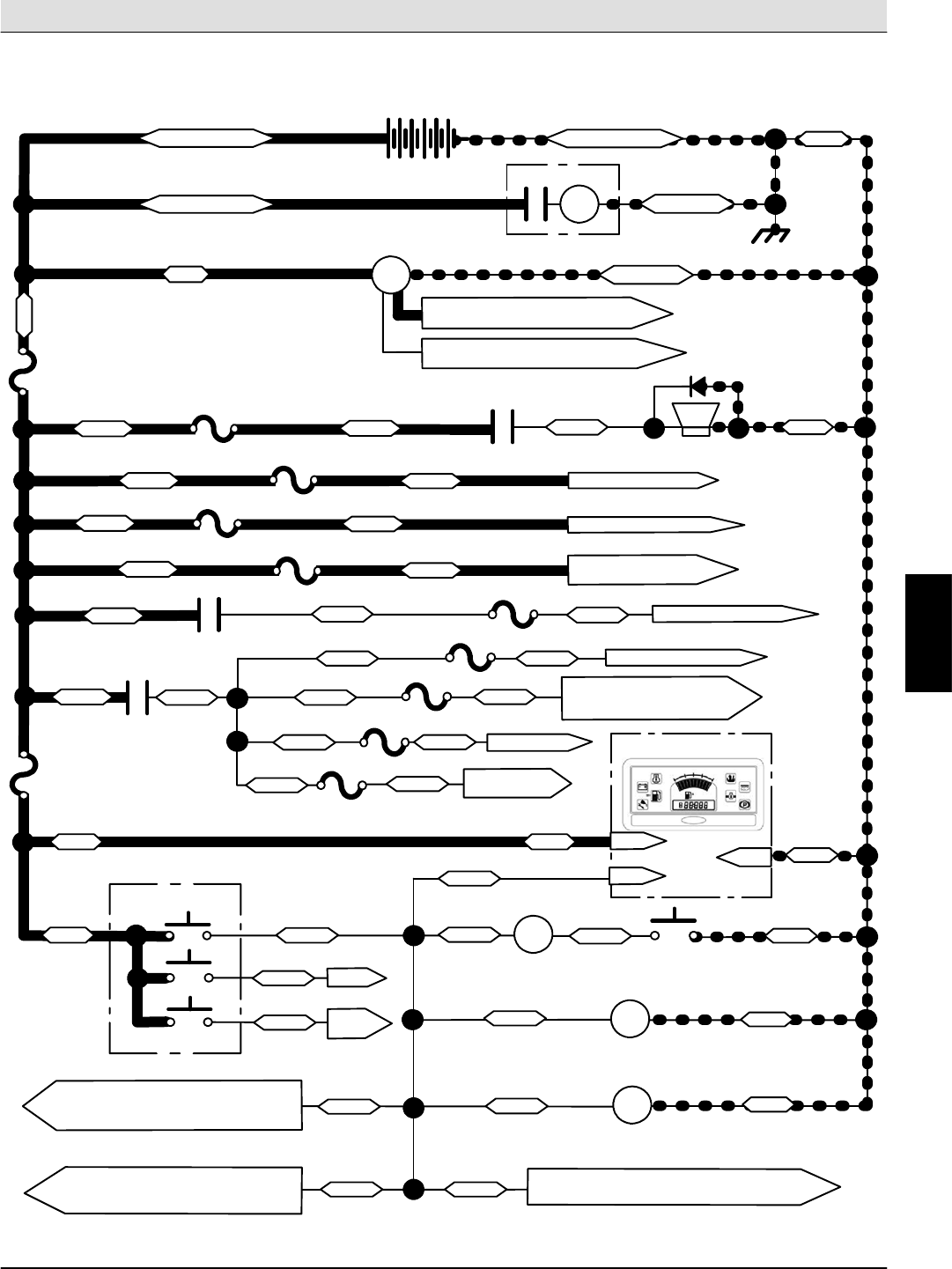
Key OFF Power Distribution (S30)
12 VDC
F11
(Inline)
60A
13/BLK
RED Battery Cable Engine Block
1/RED
1/RED
RED Battery Cable BLK Battery Cable
Engine Block
13/BLK
2/BRN
MTR2
STARTER MOTOR
ALTERNATOR
M1
HORN RELAY HORN
D6
51/PNK
LS1
4/YEL
+--
GAS/LP--To engine harness RED (B+)
DIESEL--No connection
GAS/LP--To engine harness PUR (excite)
DIESEL--15/GRN to engine harness
AB
START
GLOW
PLUGS
KEY SWITCH
S9
AB
C
D
9/WHT
7/PUR
8/GRY
OFF
6/BLU M1
HORN RELAY
13/BLK
HORN SWITCH
SW19
9/WHT 10/TAN
M2
M5
AUX 1 RELAY
AUX 2 RELAY
9/WHT 13/BLK
13/BLK
TO ENGINE SPEED SWITCH (SW6),
ALTERNATOR RESISTOR (R1), CAB
CONTACTOR (C1), & SEAT SWITCH
9/WHT
9/WHT
9/WHT
TO INDICATOR LAMPS: CHECK ENGINE
(LP9), STALLED BROOM (LP10), CLOGGED
HYD. FILTER (LP11), HOT HYD. OIL (LP12)
2/BRN
M5
AUX 2 RELAY
39/WHT
36/BLU
TO SV1 & SV3
5/GRN
F7 15A
38/GRY
F3 15A
31/PNK
F8 15A
TO SIGNAL FLASHER
85/GRN
86/BLU
F10 25A TO M9 START RELAY
(DIESEL ONLY)
75/GRN
13/BLK
20/TAN
F2
15A
2/BRN
M2
AUX 1 RELAY
F9 15A
F6 15A
19/WHT
19/WHT
19/WHT
19/WHT
F4 15A
2/BRN
6/BLU6/BLU
2/BRN
2/BRN
F1 15A
TO LIGHTING CIRCUITS
EXTRA
SWITCHED B+
EXTRA UNSWITCHED B+
P1--7
P1--5
LCD DISPLAY PANEL
P2--2
9/WHT KEY SWITCH
INPUT
TO VACUUM FAN & SHAKER SWITCH (SW18),
SHAKER RELAY (M3), SHAKER TIMER (TMR3)
9/WHT
F5 15A
TO M4 MAIN BRUSH RELAY,
ENABLE VALVE TIMER (TMR1),
SV4, SV5, SV6A, SV6B
TO M3 SHAKER RELAY
19/WHT
E
Home
Find...
Go To..
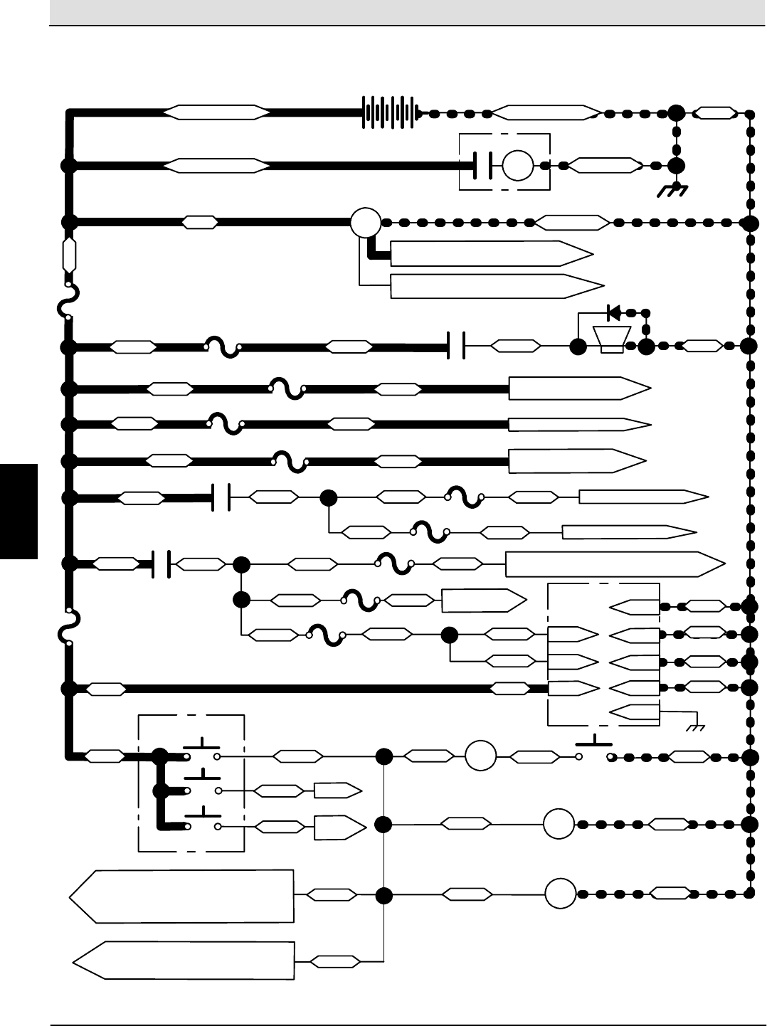
Electrical Troubleshooting S30 SERVICE INFORMATION
S30 9004086 (4--08)
68
Key OFF Power Distribution (S30XP,S30X4)
12 VDC
F11
(Inline)
60A
P1--32
13/BLK
RED Battery Cable Engine Block
1/RED
1/RED
RED Battery Cable BLK Battery Cable
Engine Block
13/BLK
2/BRN
MTR2
STARTER MOTOR
ALTERNATOR
M1
HORN RELAY HORN
D6
51/PNK
LS1
CONTROL BOARD
4/YEL
13/BLK
+--
GAS/LP--To engine harness RED (B+)
DIESEL--No connection
GAS/LP--To engine harness PUR (excite)
DIESEL--15/GRN to engine harness
AB
START
GLOW
PLUGS
KEY SWITCH
S9
AB
C
D
9/WHT
7/PUR
8/GRY
OFF
6/BLU M1
HORN RELAY
13/BLK
HORN SWITCH
S19
9/WHT 10/TAN
M2
M5
AUX 1 RELAY
AUX 2 RELAY
9/WHT 13/BLK
13/BLK
TO ALTERNATOR RESISTOR (R1), CAB
CONTACTOR (C1), & M6 ENGINE SHUT-
DOWN RELAY 9/WHT
9/WHT
9/WHT
TO INDICATOR LAMPS: CHECK ENGINE
(LP9), STALLED BROOM (LP10), CLOGGED
HYD. FILTER (LP11), HOT HYD. OIL (LP12),
2/BRN
M5
AUX 2 RELAY
39/WHT
33/ORA
TO SV1, SV3,
SV4, SV7, SV8
TO M3 SHAKER RELAY, M6 ENGINE SHUT-
DOWN RELAY, SV2, SV5, SV6A, SV6B
25/GRN
38/GRY
F3 15A
31/PNK
F8 15A
TO M3 SHAKER RELAY
& SIGNAL FLASHER
23/ORA
24/YEL
F10 25A TO M9 START RELAY
(DIESEL ONLY)
75/GRN
13/BLK
13/BLK
P1--22 13/BLK
P1--33
P1--35
P1--34
P1--2
20/TAN
20/TAN
25/GRN
F2
15A
2/BRN
M2
AUX 1 RELAY
25/GRN
F9 15A
P1--3
F6 15A
19/WHT
19/WHT
19/WHT
19/WHT
F4 15A
2/BRN
6/BLU
20/TAN
6/BLU
2/BRN
2/BRN
F1 15A
TO LIGHTING CIRCUITS
EXTRA SWITCHED B+
EXTRA UNSWITCHED B+
F7 15A
F5 15A
P1--1
PARKING BRAKE (LP18)
E
Home
Find...
Go To..
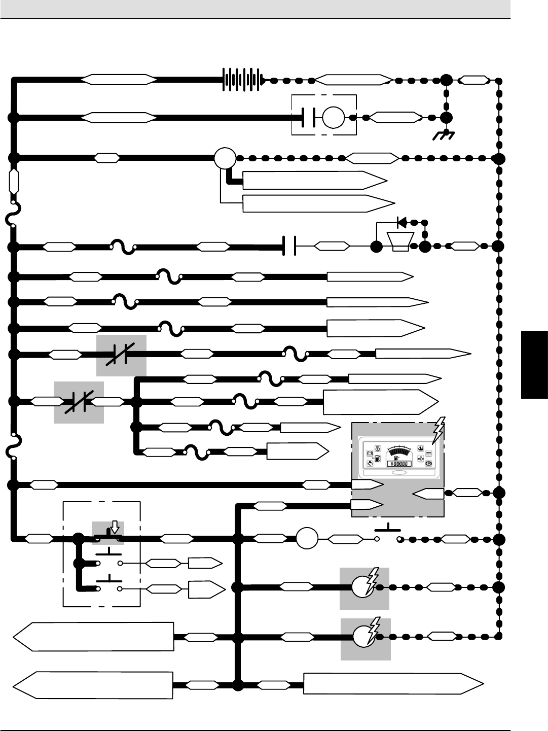
S30 SERVICE INFORMATION Electrical Troubleshooting
S30 9004086 (4--08) 69
Key ON Power Distribution (S30)
12 VDC
F11
(Inline)
60A
13/BLK
RED Battery Cable Engine Block
1/RED
1/RED
RED Battery Cable BLK Battery Cable
Engine Block
13/BLK
2/BRN
MTR2
STARTER MOTOR
ALTERNATOR
M1
HORN RELAY HORN
D6
51/PNK
LS1
4/YEL
+--
GAS/LP--To engine harness RED (B+)
DIESEL--No connection
GAS/LP--To engine harness PUR (excite)
DIESEL--15/GRN to engine harness
AB
START
GLOW
PLUGS
KEY SWITCH
S9
AB
C
D
9/WHT
7/PUR
8/GRY
RUN
6/BLU M1
HORN RELAY
13/BLK
HORN SWITCH
SW19
9/WHT 10/TAN
M2
M5
AUX 1 RELAY
AUX 2 RELAY
9/WHT 13/BLK
13/BLK
9/WHT
9/WHT
9/WHT
TO INDICATOR LAMPS: CHECK ENGINE
(LP9), STALLED BROOM (LP10), CLOGGED
HYD. FILTER (LP11), HOT HYD. OIL (LP12)
2/BRN
M5
AUX 2 RELAY
39/WHT
36/BLU
TO SV1 & SV3
5/GRN
F7 15A
38/GRY
F3 15A
31/PNK
F8 15A
TO SIGNAL FLASHER
85/GRN
86/BLU
F10 25A TO M9 START RELAY
(DIESEL ONLY)
75/GRN
13/BLK
20/TAN
F2
15A
2/BRN
M2
AUX 1 RELAY
F9 15A
F6 15A
19/WHT
19/WHT
19/WHT
19/WHT
F4 15A
2/BRN
6/BLU6/BLU
2/BRN
2/BRN
F1 15A
TO LIGHTING CIRCUITS
EXTRA
SWITCHED B+
EXTRA UNSWITCHED B+
P1--7
P1--5
LCD DISPLAY PANEL
P2--2
9/WHT
KEY SWITCH
INPUT
TO VACUUM FAN & SHAKER SWITCH (SW18),
SHAKER RELAY (M3), SHAKER TIMER (TMR3)
9/WHT
F5 15A
TO M4 MAIN BRUSH RELAY,
ENABLE VALVE TIMER (TMR1),
SV4, SV5, SV6A, SV6B
TO M3 SHAKER RELAY
19/WHT
TO ENGINE SPEED SWITCH (SW6),
ALTERNATOR RESISTOR (R1), CAB
CONTACTOR (C1), & SEAT SWITCH
E
Home
Find...
Go To..
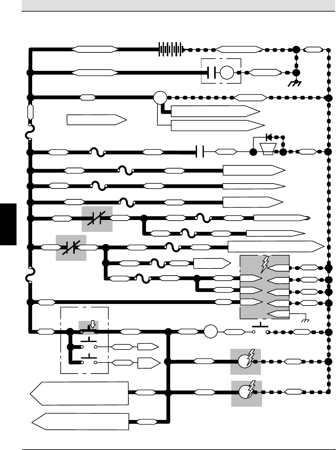
Electrical Troubleshooting S30 SERVICE INFORMATION
S30 9004086 (4--08)
70
Key ON Power Distribution (S30XP,S30X4)
12 VDC
F11
(Inline)
60A
P1--32
13/BLK
RED Battery Cable Engine Block
1/RED
1/RED
RED Battery Cable BLK Battery Cable
Engine Block
13/BLK
2/BRN
MTR2
STARTER MOTOR
ALTERNATOR
M1
HORN RELAY HORN
D6
51/PNK
LS1
4/YEL
13/BLK
+--
GAS/LP--To engine harness RED (B+)
DIESEL--No connection
GAS/LP--To engine harness PUR (excite)
DIESEL--15/GRN to engine harness
AB
START
GLOW
PLUGS
KEY SWITCH
S9
AB
C
D
9/WHT
7/PUR
8/GRY
RUN
6/BLU M1
HORN RELAY
13/BLK
HORN SWITCH
S19
9/WHT 10/TAN
M2
M5
AUX 1 RELAY
AUX 2 RELAY
9/WHT 13/BLK
13/BLK
9/WHT
9/WHT
9/WHT
2/BRN
M5
AUX 2 RELAY
39/WHT
33/ORA
TO SV1, SV3,
SV4, SV7, SV8
TO M3 SHAKER RELAY,
SV2, SV5, SV6A, SV6B
25/GRN
38/GRY
F3 15A
31/PNK
F8 15A
TO M3 SHAKER RELAY
& SIGNAL FLASHER
23/ORA
24/YEL
F10 25A TO M9 START RELAY
(DIESEL ONLY)
75/GRN
13/BLK
13/BLK
P1--22 13/BLK
P1--33
P1--35
P1--34
P1--2
20/TAN
20/TAN
25/GRN
F2
15A
2/BRN
M2
AUX 1 RELAY
25/GRN
F9 15A
P1--3
F6 15A
19/WHT
19/WHT
19/WHT
19/WHT
F4 15A
2/BRN
6/BLU
20/TAN
6/BLU
2/BRN
2/BRN
F1 15A
TO LIGHTING CIRCUITS
EXTRA SWITCHED B+
EXTRA UNSWITCHED B+
F5 15A
F7 15A
P1--1
TO ALTERNATOR RESISTOR (R1), CAB
CONTACTOR (C1), & M6 ENGINE SHUT-
DOWN RELAY
TO INDICATOR LAMPS: CHECK ENGINE
(LP9), STALLED BROOM (LP10), CLOGGED
HYD. FILTER (LP11), HOT HYD. OIL (LP12),
PARKING BRAKE (LP18)
TO M3 SHAKER RELAY, M6 ENGINE SHUT-
DOWN RELAY, SV2, SV5, SV6A, SV6B
CONTROL BOARD
E
Home
Find...
Go To..
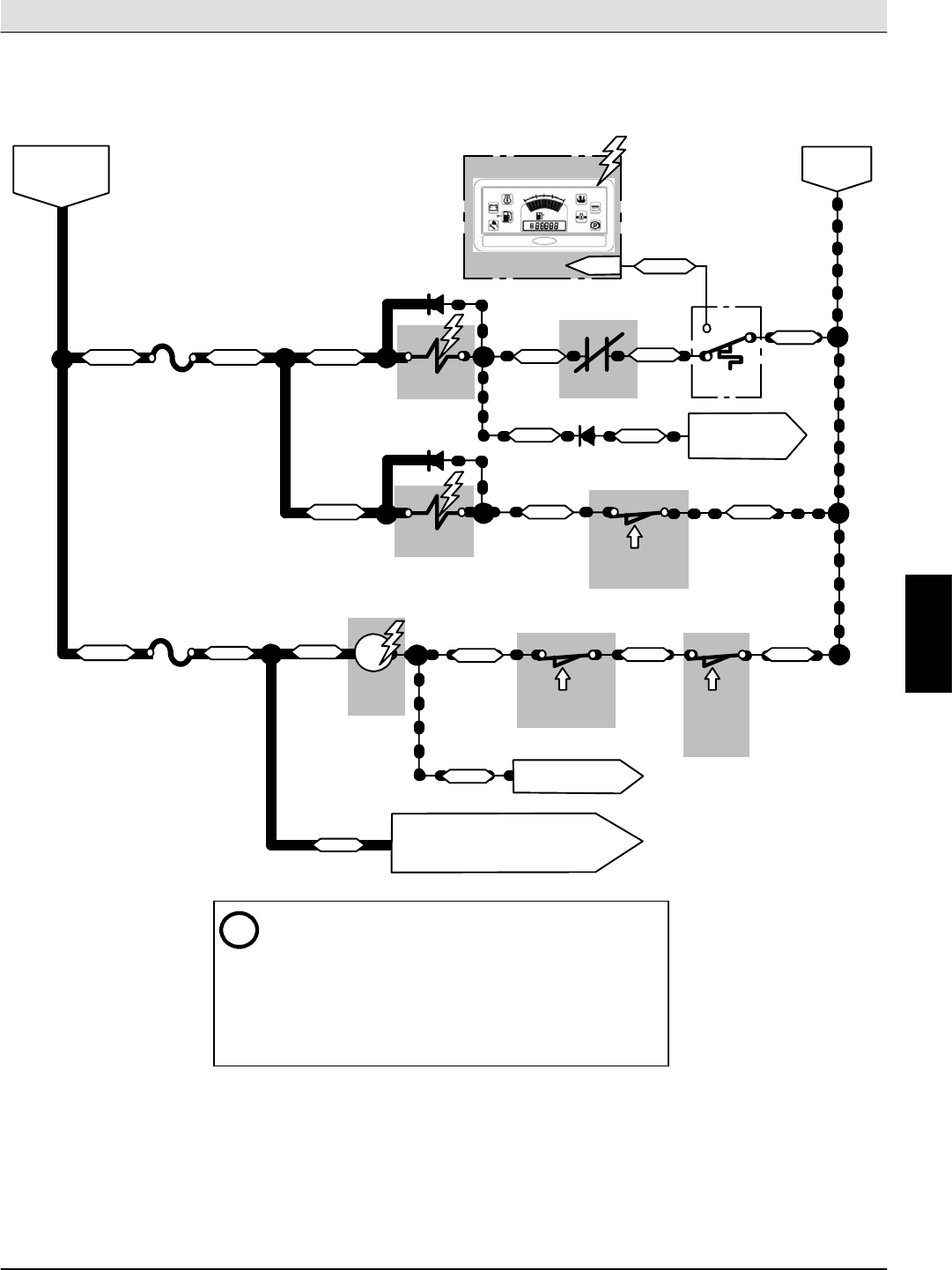
S30 SERVICE INFORMATION Electrical Troubleshooting
S30 9004086 (4--08) 71
Main & Side Brushes ON (S30)
M4
MAIN BRUSH
RELAY
P2--5
LCD DISPLAY PANEL
Conditions: Key ON (RUN), Main & Side Brushes Lowered. Hopper Down
SV1
SWITCHED B+
FROM AUX. 1
RELAY (M2)
F5
15A
F6
15A
19/WHT
19/WHT
39/WHT 39/WHT
39/WHT
D7
D11
28/GRY
BATTERY
NEGATIVE
MAIN BRUSH
SV3
SIDE BRUSH
SW14
THERMO--
SENTRY
42/BRN
D8 TO VACUUM
FAN & SHAKER
SWITCH (SW18)
52/BRN
42/BRN 73/ORG
SW7
LEVER SWITCH
SIDE BRUSH
SW5
LEVER SWITCH
MAIN BRUSH
SW16
POSITION
HOPPER
SWITCH
M4
36/BLU 36/BLU
VALVE
VALVE
36/BLU
49/WHT
TO HOPPER ENABLE VALVE (SV4),
HOPPER DOOR VALVE (SV5), HOPPER
RAISE/LOWER VALVES (SV6A,SV6B),
& ENABLE VALVE TIMER (TMR1)
68/GRY
13/BLK
13/BLK
13/BLK
41/PNK
(Brush Lowered)
(Brush Lowered)
(Hopper
Lowered)
iThermo--Sentry switch (SW14) is shown in the normal
NON--activated position (13/BLK connected to 52/BRN). The
switch is activated (13/BLK connected to 28/GRY) when the
Hopper air temperature exceeds 71
_
C (160
_
F). The Hopper
Fire indicator on the LCD panel will also illuminate when this
switch is activated. When the temperature falls below 60
_
C
(140
_
F), the switch will return to the NON--activated position,
and the indicator light will turn OFF.
NOTE: Switch closes
only when in the fully
lowered position
MAIN
RELAY
49/WHT TO HOPPER DOOR
SWITCH (SW3)
BRUSH
E
Home
Find...
Go To..
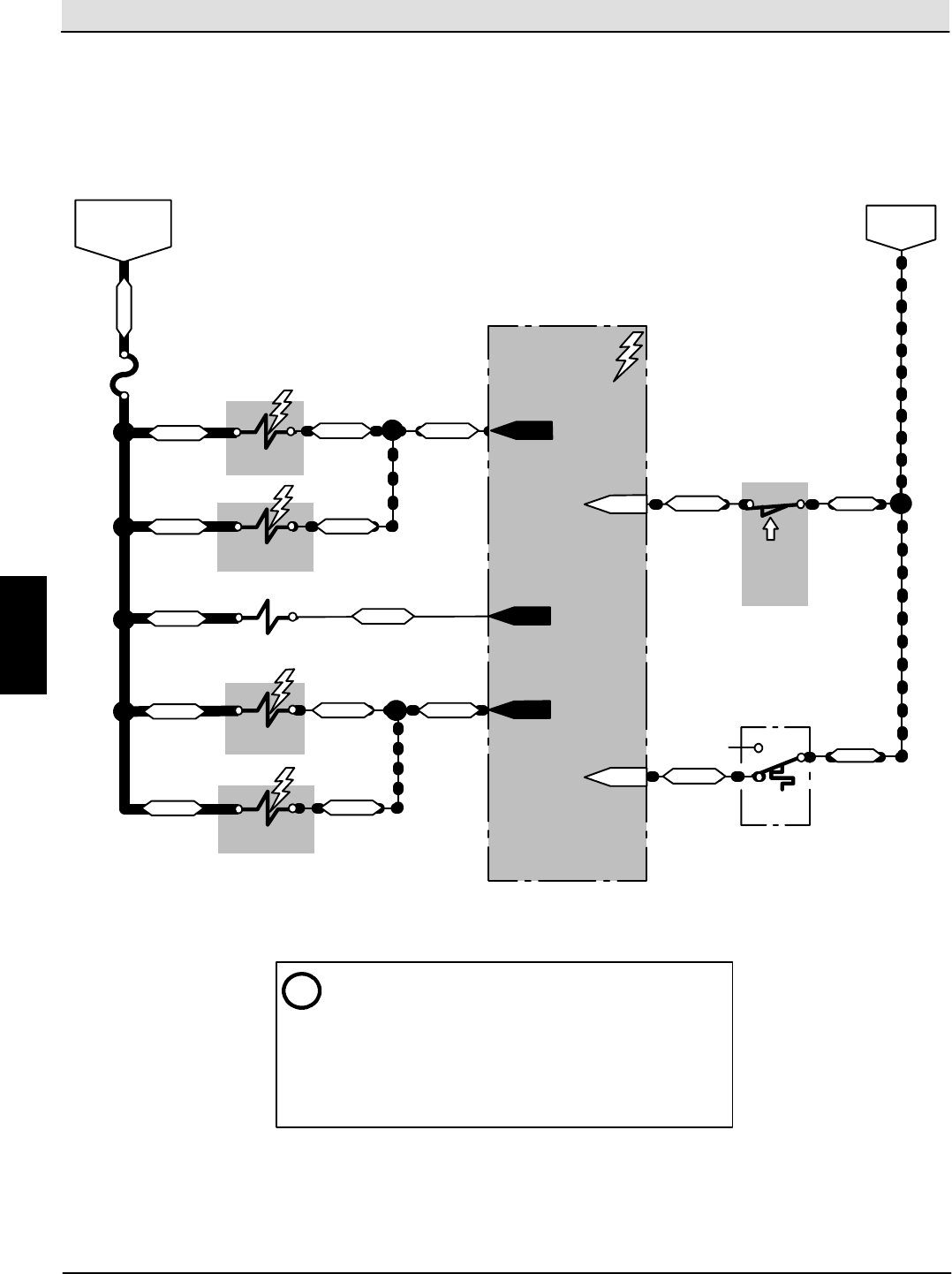
Electrical Troubleshooting S30 SERVICE INFORMATION
S30 9004086 (4--08)
72
Main & Side Brushes ON (S30XP,S30X4)
SW16
POSITION
HOPPER
SWITCH
(Hopper
Lowered)
P1--5
Conditions: Key ON (RUN), Sweep System Activated, Side Brush(es) Activated. Hopper Down
SV1
SWITCHED B+
FROM AUX. 1
RELAY (M2)
F5
15A
19/WHT
39/WHT 42/BRN
BATTERY
NEGATIVE
MAIN BRUSH
SV3
SIDE BRUSH S14
THERMO--
SENTRY
ON VALVE
ON VALVE
13/BLK
iThermo--Sentry switch (S14) is shown in the normal
NON--activated position (13/BLK connected to 52/BRN). The
switch is activated (13/BLK connected to 28/GRY) when the
Hopper air temperature exceeds 71
_
C (160
_
F). The Hopper
Fire indicator on the control panel will also illuminate when
this switch is activated. When the temperature falls below
60
_
C (140
_
F), the switch will return to the NON--activated
position, and the indicator light will turn OFF.
SV8
MAIN BRUSH
LOWER VALVE
SV7
SIDE BRUSH
LOWER VALVE
SV4
ENABLE
VALVE
39/WHT
39/WHT
39/WHT
39/WHT
CONTROL BOARD
P1--4
P1--31
42/BRN
42/BRN
40/TAN
41/PNK 41/PNK
41/PNK
13/BLK
X
52/BRN
44/YEL
P1--27
P1--13
NOTE: Switch closes only when
in the fully lowered position
E
Home
Find...
Go To..
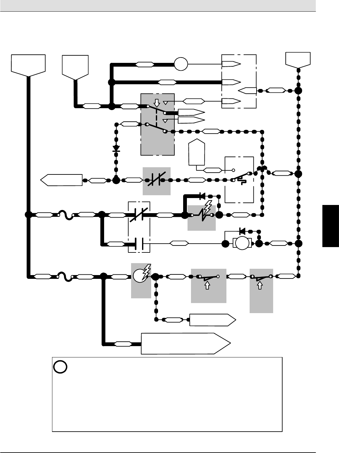
S30 SERVICE INFORMATION Electrical Troubleshooting
S30 9004086 (4--08) 73
Vacuum Fan ON (S30)
M4
MAIN BRUSH
Conditions: Key ON (RUN), Main Brush Lowered. Hopper Down
SWITCHED B+
FROM AUX. 1
RELAY (M2)
F9
15A
F6
15A
D10
SV2
VACUUM
SW14
THERMO--
SENTRY
D8
TO MAIN BRUSH
VALVE (SV1) 52/BRN
SW16
POSITION
HOPPER
SWITCH
RELAY
19/WHT 86/BLU
FAN VALVE
13/BLK
13/BLK
13/BLK
43/ORG
(Hopper
Lowered)
i-- The Thermo--Sentry switch (SW14) is shown in the normal NON--activated position
(13/BLK connected to 52/BRN). The switch is activated (13/BLK connected to 28/GRY)
when the Hopper air temperature exceeds 71
_
C (160
_
F). The Hopper Fire indicator on the
LCD panel will also illuminate when this switch is activated. When the temperature falls
below 60
_
C (140
_
F), the switch will return to the NON--activated position, and the
indicator light will turn OFF.
-- The Vacuum Fan & Shaker Switch (SW18) is a 3--position switch. This drawing shows
the switch in the Vacuum Fan position, which will remain in this position until the
operator selects the OFF (center) position, or performs a Shaker cycle (momentary
position).
SW18
SWITCH
SWITCH
VACUUM FAN
& SHAKER
BATTERY
NEGATIVE
SWITCHED
B+ FROM
IGNITION
SWITCH
9/WHT
9/WHT9/WHT
33/ORG
9/WHT
M3
UNUSED
SHAKER
TIMER
TMR3
PIN 1
PIN 3
PIN 6
PIN 2
SHAKER
RELAY
9/WHT
UNUSED
28/GRY
(Vac. Fan ON)
42/BRN
42/BRN
73/ORG
M3
SHAKER
86/BLU
M3
RELAY
86/BLU
72/BRN
72/BRN
TO LCD
DISPLAY
PIN P2-- 5
MTR1
SV2
D1
SHAKER
MOTOR
13/BLK32/BRN
19/WHT 36/BLU
1
2
5
6
4
8
COM
NC
NO
NOTE: Switch closes
only when in the fully
lowered position
SW5
LEVER SWITCH
MAIN BRUSH
M4
36/BLU
36/BLU
49/WHT 68/GRY
(Brush Lowered)
MAIN
RELAY
49/WHT TO HOPPER DOOR
SWITCH (SW3)
BRUSH
TO HOPPER ENABLE VALVE (SV4),
HOPPER DOOR VALVE (SV5), HOPPER
RAISE/LOWER VALVES (SV6A,SV6B),
& ENABLE VALVE TIMER (TMR1)
E
Home
Find...
Go To..
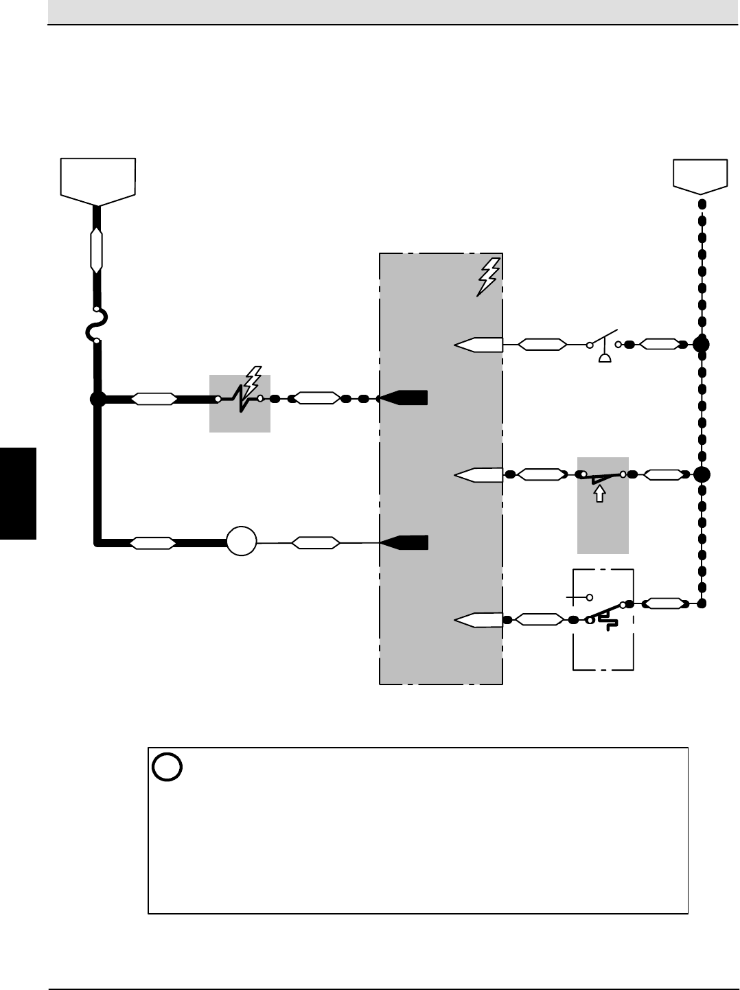
Electrical Troubleshooting S30 SERVICE INFORMATION
S30 9004086 (4--08)
74
Vacuum Fan ON (S30XP,S30X4)
SW16
POSITION
HOPPER
SWITCH
(Hopper
Lowered)
Conditions: Key ON (RUN), Sweep System Activated, Vacuum System Activated. Hopper Down
SV2
SWITCHED B+
FROM AUX. 1
RELAY (M2)
F6
15A
19/WHT
33/ORA
BATTERY
NEGATIVE
VACUUM
S14
THERMO--
SENTRY
FAN VALVE
13/BLK
i-- Thermo--Sentry switch (S14) is shown in the normal NON--activated position (13/BLK
connected to 52/BRN). The switch is activated (13/BLK NOT connected to 52/BRN) when the
Hopper air temperature exceeds 71
_
C (160
_
F). The LCD screen on the control panel will also
show “F5: HOPPER FIRE” when this switch is activated, all sweeping functions will turn OFF
and the hopper door will close. When the temperature falls below 60
_
C (140
_
F), the switch will
return to the NON--activated position.
-- Clogged Dust Filter Switch (S8) is shown in the normal NON--activated position (30/TAN NOT
connected to 13/BLK), and will close when the dust filter becomes clogged. The switch closes
when the negative pressure reaches 28 cm (11 in) of water lift (vacuum). The LCD screen on the
control panel will also show “F4: SHAKER FILTER” when this switch is closed.
CONTROL BOARD
P1--11
36/BLU
13/BLK
X
52/BRN
44/YEL
P1--27
P1--13
33/ORA M3
SHAKER RELAY
34/YEL
P1--10
S8
P1--14 13/BLK
30/TAN
CLOGGED DUST
FILTER SWITCH
COM
NC
NO
SWITCH
NOTE:
Switch
closes only
when in the
fully lowered
position
E
Home
Find...
Go To..
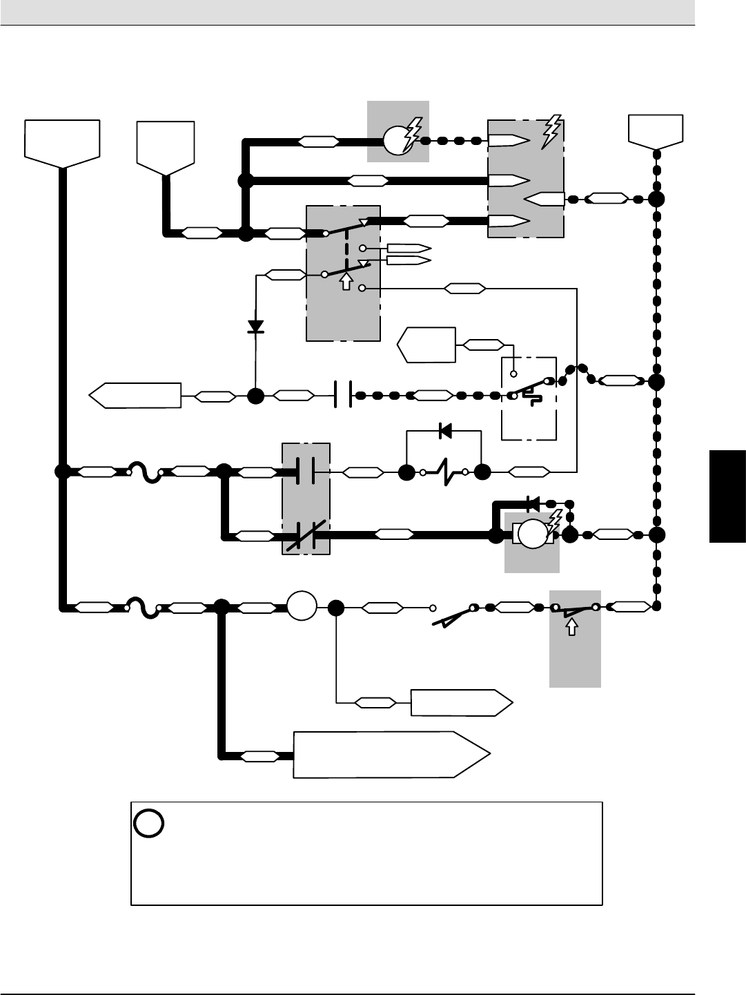
S30 SERVICE INFORMATION Electrical Troubleshooting
S30 9004086 (4--08) 75
Filter Shaker ON (S30)
M4
MAIN BRUSH
Conditions: Key ON (RUN), Hopper Down
SWITCHED B+
FROM AUX. 1
RELAY (M2)
F9
15A
F6
15A
D10
SV2
VACUUM
SW14
THERMO--
SENTRY
D8
TO MAIN BRUSH
VALVE (SV1) 52/BRN
SW16
POSITION
HOPPER
SWITCH
RELAY
19/WHT 86/BLU
FAN VALVE
13/BLK
13/BLK
13/BLK
43/ORG
(Hopper
Lowered)
i-- The Vacuum Fan & Shaker Switch (SW18) is a 3--position switch. This drawing
shows the switch in the Shaker position, which must be held, and then released
(momentary switch) to initiate a Shaker cycle. When released, the switch will
return to the center OFF position.
-- When B+ is momentarily applied to Pin 6 of the Shaker Timer (TMR3) , a 30
second Shaker cycle begins, applying Battery Negative to Pin 1 of TMR3.
SW18
SWITCH
BATTERY
NEGATIVE
SWITCHED
B+ FROM
IGNITION
SWITCH
9/WHT
9/WHT9/WHT
33/ORG
9/WHT
SHAKER
TIMER
TMR3
PIN 3
PIN 6
PIN 2
SHAKER
RELAY
9/WHT
28/GRY
42/BRN
42/BRN
73/ORG
M3
SHAKER
86/BLU
M3
RELAY
86/BLU
72/BRN
72/BRN
TO LCD
DISPLAY
PIN P2-- 5
MTR1
SV2
D1
SHAKER
MOTOR
13/BLK32/BRN
19/WHT 36/BLU
PIN 1
M3
SWITCH
VACUUM FAN
& SHAKER
(Shaker ON)
1
2
5
6
4
8
UNUSED
UNUSED
NOTE: Switch closes
only when in the fully
lowered position
SW5
LEVER SWITCH
MAIN BRUSH
M4
36/BLU
36/BLU
49/WHT 68/GRY
MAIN
RELAY
49/WHT TO HOPPER DOOR
SWITCH (SW3)
BRUSH
TO HOPPER ENABLE VALVE (SV4),
HOPPER DOOR VALVE (SV5), HOPPER
RAISE/LOWER VALVES (SV6A,SV6B),
& ENABLE VALVE TIMER (TMR1)
(Brush Raised)
E
Home
Find...
Go To..
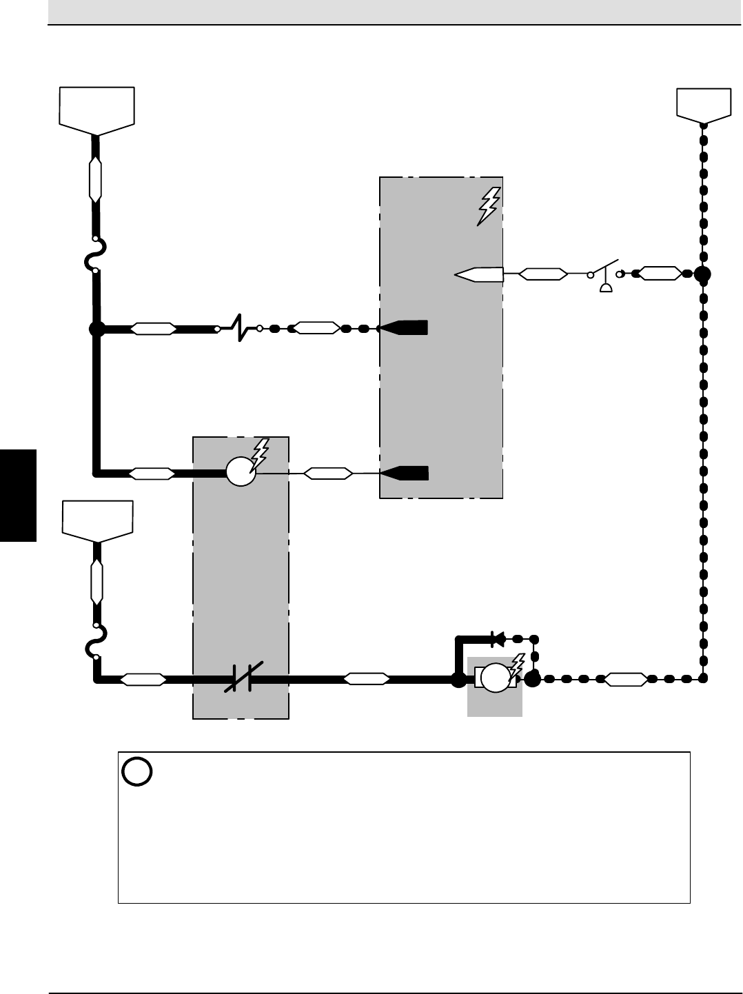
Electrical Troubleshooting S30 SERVICE INFORMATION
S30 9004086 (4--08)
76
Filter Shaker ON (S30XP,S30X4)
Conditions: Key ON (RUN), Shaker System Activated
SV2
SWITCHED B+
FROM AUX. 1
RELAY (M2)
F6
15A
19/WHT
33/ORA
BATTERY
NEGATIVE
VACUUM
FAN VALVE
i-- When activated, the Shaker System will run for 30 seconds. The Shaker System is automatically
activated when turning the sweeping system OFF, or can be activated anytime by pressing the Shaker
button. Pressing the Shaker button during sweeping will turn OFF the Vacuum Fan during the Shaker
cycle. The Shaker System is the only sweeping related function that can be activated with the Hopper
in the raised position.
-- Clogged Dust Filter Switch (S8) is shown in the normal NON--activated position (30/TAN NOT
connected to 13/BLK), and will close when the dust filter becomes clogged. The switch closes when
the negative pressure reaches 28 cm (11 in) of water lift (vacuum). The LCD screen on the control
panel will also show “F4: SHAKER FILTER” when this switch is closed.
CONTROL BOARD
P1--11
36/BLU
33/ORA M3
SHAKER RELAY
34/YEL
P1--10
S8
P1--14 13/BLK
30/TAN
CLOGGED DUST
FILTER SWITCH
UNSWITCHED
B+ FROM
FUSE F11
F3
15A M3
SHAKER
RELAY
MTR1
D1
SHAKER
MOTOR
2/BRN
31/PNK 32/BRN 13/BLK
E
Home
Find...
Go To..
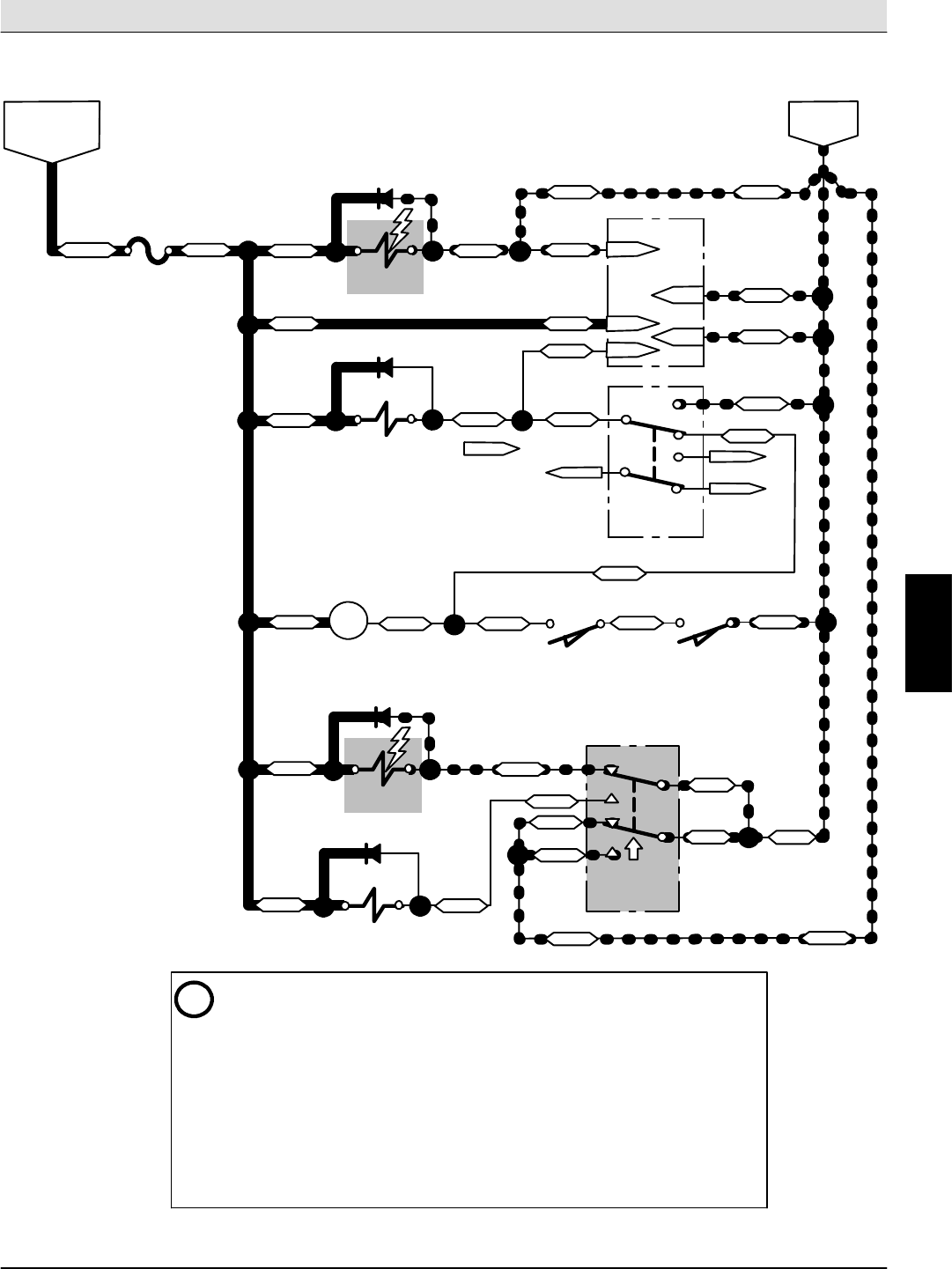
S30 SERVICE INFORMATION Electrical Troubleshooting
S30 9004086 (4--08) 77
Hopper Lift (S30)
Conditions: Key ON (RUN), Hopper Door Closed
SV4
SWITCHED B+
FROM AUX. 1
RELAY (M2)
F6
15A
19/WHT
D15
ENABLE
SW5
LEVER SWITCH
MAIN BRUSH
SW16
POSITION
HOPPER
SWITCH
MAIN BRUSH
RELAY
36/BLU
VALVE
49/WHT 68/GRY 13/BLK
(Brush Raised) (Hopper Lifted)
36/BLU
SV5
D12
HOPPER
VALVE
DOOR OPEN
SV6A
D13
HOPPER
LIFT VALVE
SV6B
D14
HOPPER
VALVE
LOWER
SW22
SWITCH
HOPPER
LIFT/LOWER
1
2
56
4
8
13/BLK13/BLK
13/BLK
(Hopper Lift)
M4
36/BLU
36/BLU
36/BLU
36/BLU
SW3
SWITCH
HOPPER
DOOR
(Automatic)
ENABLE VALVE
TIMER
TMR1
PIN 5
PIN 2
36/BLU
37/PUR
PIN 3
PIN 1 13/BLK
13/BLK
49/WHT
13/BLK
49/WHT
49/WHT
PIN 4
BATTERY
NEGATIVE
40/TAN 40/TAN
40/TAN
40/TAN
35/GRN 35/GRN
35/GRN
48/GRY
48/GRY
40/TAN
40/TAN
40/TAN
40/TAN
1
2
6
4
5
8
36/BLU
i-- The Hopper Lift/Lower Switch (SW22) is a 3--position switch. This drawing
shows the switch in the Hopper Lift position, which must be held (momentary
switch) while the Hopper is being lifted. When released, the switch will return to
the center OFF position, and the Hopper will remain in the current position.
-- Enable Valve (SV4) must be energized when Lifting or Lowering the Hopper, or
when Opening or Closing the Hopper Door. To open the Hopper Door, the Enable
Valve (SV4) and the Hopper Door Open Valve (SV5) must be energized. To close
the Hopper Door, ONLY the Enable Valve (SV4) must be energized (SV5 is OFF).
-- The Enable Valve Timer (TMR1) energizes the Enable Valve (SV4) for 6 seconds
when triggered. Triggering of TMR1 occurs when the Hopper Door Open Valve
(SV5) is turned ON or OFF, and is input on Pin 4 of TMR1.
UNUSED UNUSED
UNUSED
UNUSED
NOTE: Switch closes
only when in the fully
lowered position
E
Home
Find...
Go To..
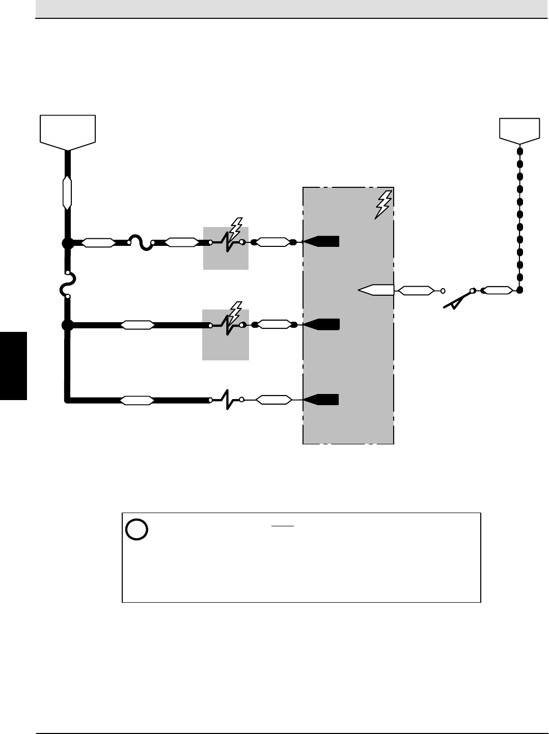
Electrical Troubleshooting S30 SERVICE INFORMATION
S30 9004086 (4--08)
78
Hopper Lift (S30XP,S30X4)
SW16
POSITION
HOPPER
SWITCH
(Hopper
Raised)
Conditions: Key ON (RUN)
SWITCHED B+
FROM AUX. 1
RELAY (M2)
F6
15A
19/WHT
BATTERY
NEGATIVE
13/BLK
i-- The Enable Valve (SV4) is ON ONLY during the following Hopper related functions:
1) Hopper Lift
2) Hopper Lower
3) Hopper Door Open
4) Hopper Door Close
-- Lifting the Hopper or closing the Hopper Door turns OFF all sweeping related
functions when the One--Step system is ON.
SV4
ENABLE
VALVE
39/WHT
CONTROL BOARD
P1--4
P1--31
40/TAN
44/YEL
P1--27
F5
15A
19/WHT
SV6A
HOPPER
VALVE
33/ORA P1--8
37/PUR
LIFT
SV6B
HOPPER
VALVE
LOWER
P1--9
33/ORA 48/GRY
NOTE: Switch closes only when
in the fully lowered position
E
Home
Find...
Go To..
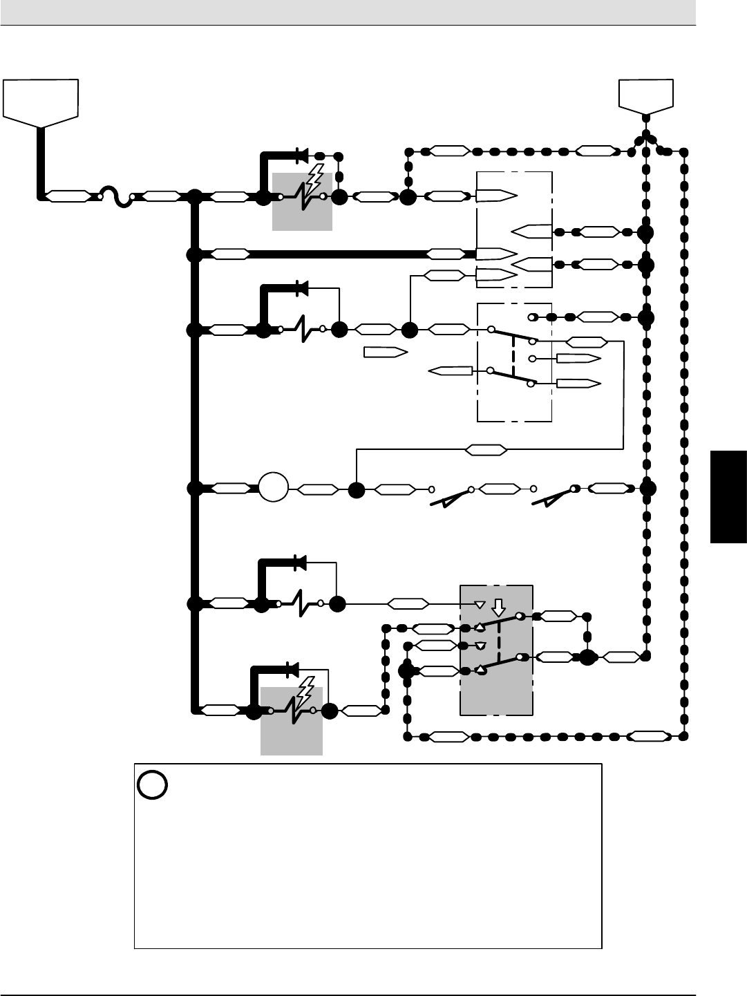
S30 SERVICE INFORMATION Electrical Troubleshooting
S30 9004086 (4--08) 79
Hopper Lower (S30)
Conditions: Key ON (RUN), Hopper Door Closed
SV4
SWITCHED B+
FROM AUX. 1
RELAY (M2)
F6
15A
19/WHT
D15
ENABLE
SW5
LEVER SWITCH
MAIN BRUSH
SW16
POSITION
HOPPER
SWITCH
MAIN BRUSH
RELAY
36/BLU
VALVE
49/WHT 68/GRY 13/BLK
(Brush Raised) (Hopper Lifted)
36/BLU
SV5
D12
HOPPER
VALVE
DOOR OPEN
SV6A
D13
HOPPER
LIFT VALVE
SV6B
D14
HOPPER
VALVE
LOWER
SW22
SWITCH
HOPPER
LIFT/LOWER
1
2
56
4
8
13/BLK13/BLK
13/BLK
(Hopper Lower)
M4
36/BLU
36/BLU
36/BLU
36/BLU
SW3
SWITCH
HOPPER
DOOR
(Automatic)
ENABLE VALVE
TIMER
TMR1
PIN 5
PIN 2
36/BLU
37/PUR
PIN 3
PIN 1 13/BLK
13/BLK
49/WHT
13/BLK
49/WHT
49/WHT
PIN 4
BATTERY
NEGATIVE
40/TAN 40/TAN
40/TAN
40/TAN
35/GRN 35/GRN
35/GRN
40/TAN
40/TAN
40/TAN
40/TAN
1
2
6
4
5
8
36/BLU
UNUSED UNUSED
UNUSED
UNUSED
48/GRY
48/GRY
i-- The Hopper Lift/Lower Switch (SW22) is a 3--position switch. This drawing
shows the switch in the Hopper Lower position, which must be held (momentary
switch) while the Hopper is being lowered. When released, the switch will return to
the center OFF position, and the Hopper will remain in the current position.
-- Enable Valve (SV4) must be energized when Lifting or Lowering the Hopper, or
when Opening or Closing the Hopper Door. To open the Hopper Door, the Enable
Valve (SV4) and the Hopper Door Open Valve (SV5) must be energized. To close
the Hopper Door, ONLY the Enable Valve (SV4) must be energized (SV5 is OFF).
-- The Enable Valve Timer (TMR1) energizes the Enable Valve (SV4) for 6 seconds
when triggered. Triggering of TMR1 occurs when the Hopper Door Open Valve
(SV5) is turned ON or OFF, and is input on Pin 4 of TMR1.
NOTE: Switch closes
only when in the fully
lowered position
E
Home
Find...
Go To..
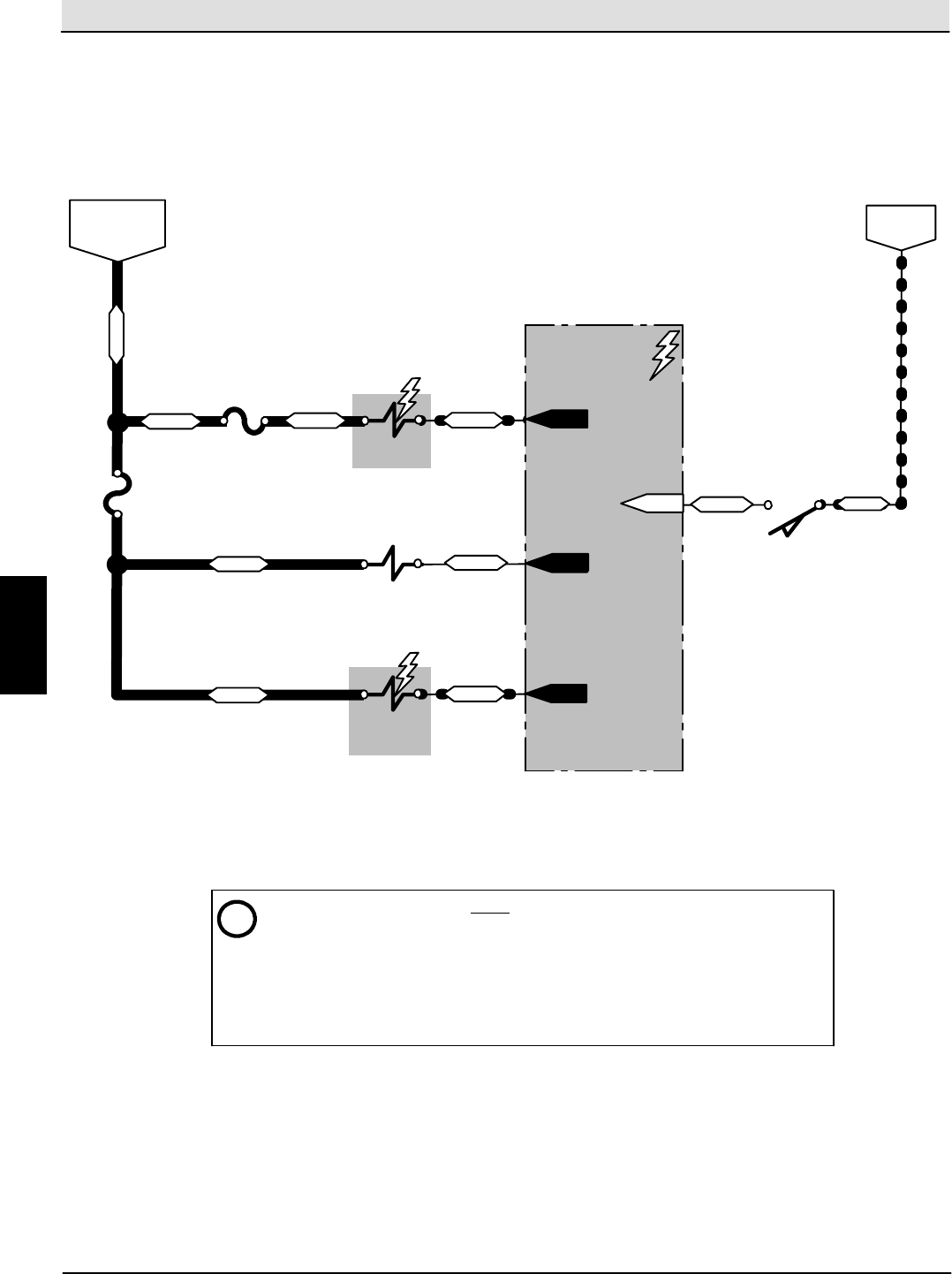
Electrical Troubleshooting S30 SERVICE INFORMATION
S30 9004086 (4--08)
80
Hopper Lower (S30XP,S30X4)
SW16
POSITION
HOPPER
SWITCH
(Hopper
Raised)
Conditions: Key ON (RUN)
SWITCHED B+
FROM AUX. 1
RELAY (M2)
F6
15A
19/WHT
BATTERY
NEGATIVE
13/BLK
i-- The Enable Valve (SV4) is ON ONLY during the following Hopper related functions:
1) Hopper Lift
2) Hopper Lower
3) Hopper Door Open
4) Hopper Door Close
-- Lifting the Hopper or closing the Hopper Door turns OFF all sweeping related
functions when the One--Step system is ON.
SV4
ENABLE
VALVE
39/WHT
CONTROL BOARD
P1--4
P1--31
40/TAN
44/YEL
P1--27
F5
15A
19/WHT
SV6A
HOPPER
VALVE
33/ORA P1--8
37/PUR
LIFT
SV6B
HOPPER
VALVE
LOWER
P1--9
33/ORA 48/GRY
NOTE: Switch closes only when
in the fully lowered position
E
Home
Find...
Go To..
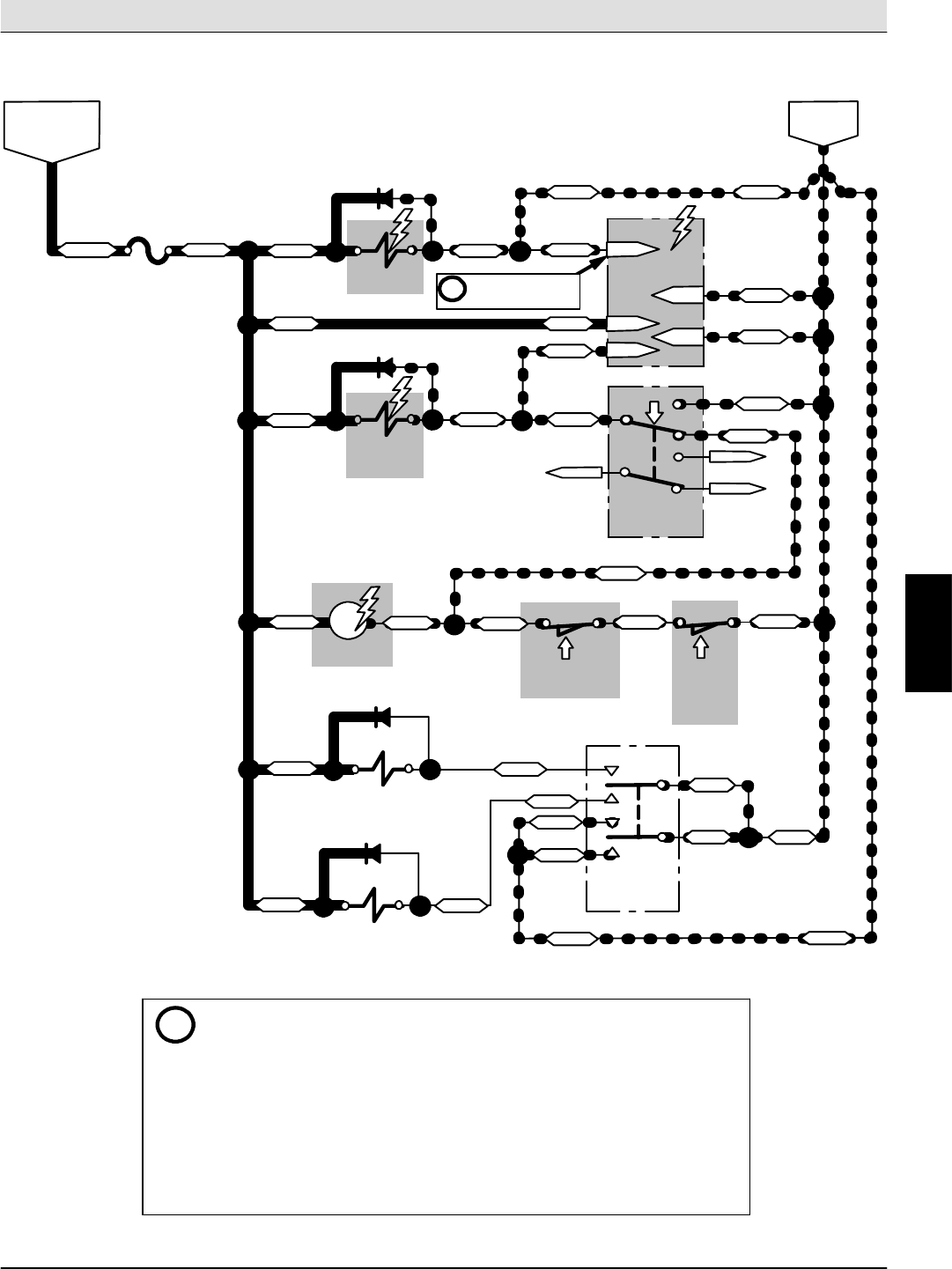
S30 SERVICE INFORMATION Electrical Troubleshooting
S30 9004086 (4--08) 81
Hopper Door Open -- Automatic (S30)
SV4
SWITCHED B+
FROM AUX. 1
RELAY (M2)
F6
15A
19/WHT
D15
ENABLE
MAIN BRUSH
RELAY
36/BLU
VALVE
36/BLU
SV5
D12
HOPPER
VALVE
DOOR OPEN
SV6A
D13
HOPPER
LIFT VALVE
SV6B
D14
HOPPER
VALVE
LOWER
SW22
2
56
4
8
13/BLK13/BLK
13/BLK
(OFF)
36/BLU
36/BLU
36/BLU
36/BLU
SW3
SWITCH
HOPPER
DOOR
(Automatic)
ENABLE VALVE
TIMER
TMR1
PIN 5
PIN 2
36/BLU
37/PUR
PIN 3
PIN 1 13/BLK
13/BLK
13/BLK
40/TAN 40/TAN
40/TAN
40/TAN
40/TAN
40/TAN
40/TAN
1
2
6
4
5
8
36/BLU
UNUSED
UNUSED
UNUSED
48/GRY
48/GRY
1
SWITCH
LIFT/LOWER
HOPPER
Conditions: Key ON (RUN), Main Brush Lowered, Hopper Down
SW5
LEVER SWITCH
MAIN BRUSH
SW16
POSITION
HOPPER
SWITCH
68/GRY
(Brush Lowered)
(Hopper
Lowered)
13/BLK
M4 49/WHT
49/WHT
49/WHT
49/WHT
ENABLE
35/GRN 35/GRN
35/GRN PIN 4
40/TAN
BATTERY
NEGATIVE
-- The Hopper Door Switch (SW3) is a 2--position switch. This drawing shows the
switch in the Automatic Door position, which automatically opens the Hopper
Door when sweeping, and closes it when the sweeping function is turned OFF.
-- Enable Valve (SV4) must be energized when Lifting or Lowering the Hopper, or
when Opening or Closing the Hopper Door. To open the Hopper Door, the Enable
Valve (SV4) and the Hopper Door Open Valve (SV5) must be energized. To close
the Hopper Door, ONLY the Enable Valve (SV4) must be energized (SV5 is OFF).
-- The Enable Valve Timer (TMR1) energizes the Enable Valve (SV4) for 6 seconds
when triggered. Triggering of TMR1 occurs when the Hopper Door Open Valve
(SV5) is turned ON or OFF, and is input on Pin 4 of TMR1.
Six second battery
negative output
on Pin 5.
i
NOTE:
Switch
closes
only when
in the fully
lowered
position
i
E
Home
Find...
Go To..
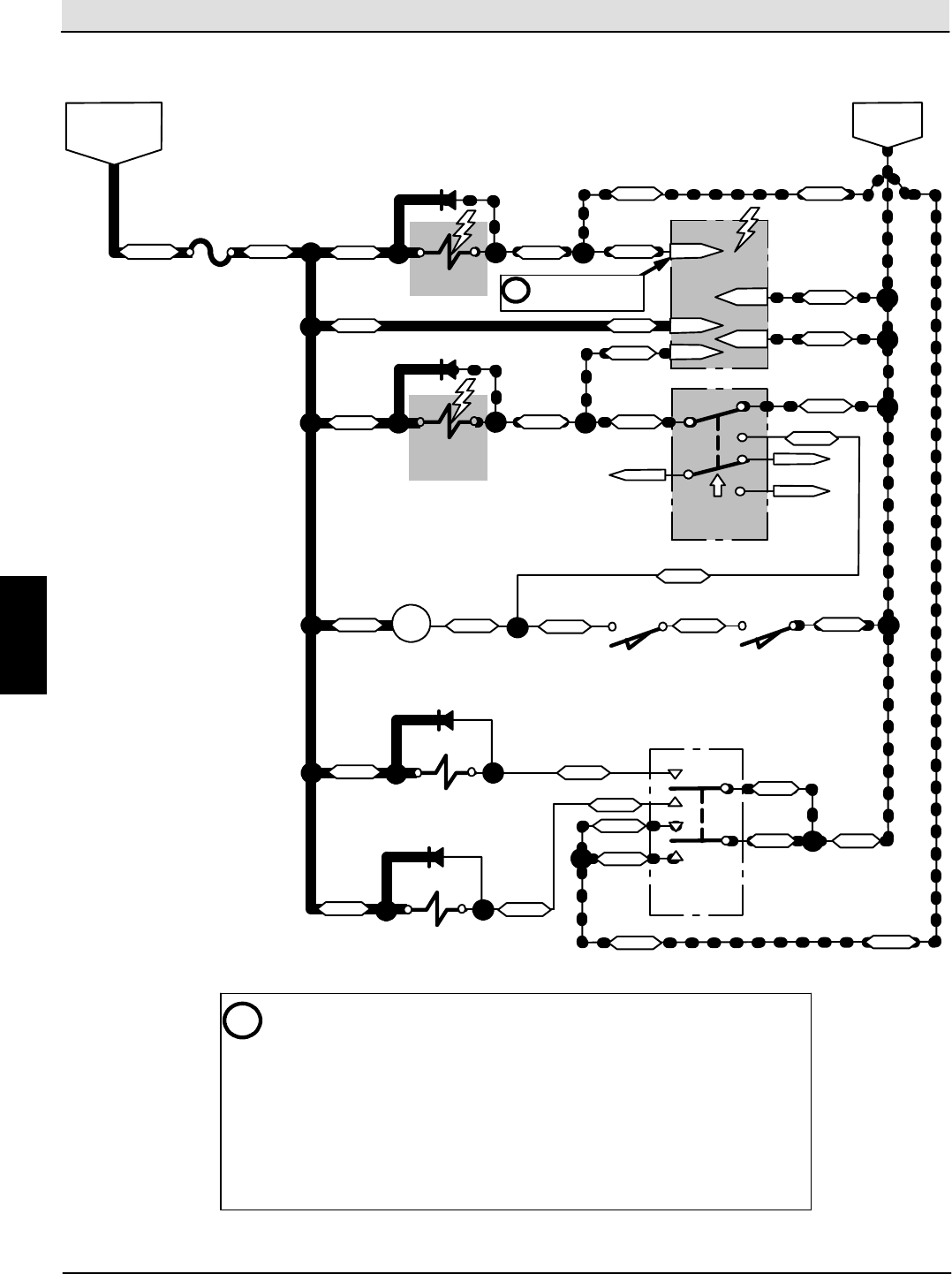
Electrical Troubleshooting S30 SERVICE INFORMATION
S30 9004086 (4--08)
82
Hopper Door Open -- Manual (S30)
SV4
SWITCHED B+
FROM AUX. 1
RELAY (M2)
F6
15A
19/WHT
D15
ENABLE
MAIN BRUSH
RELAY
36/BLU
VALVE
36/BLU
SV5
D12
HOPPER
VALVE
DOOR OPEN
SV6A
D13
HOPPER
LIFT VALVE
SV6B
D14
HOPPER
VALVE
LOWER
SW22
2
56
4
8
13/BLK13/BLK
13/BLK
(OFF)
36/BLU
36/BLU
36/BLU
36/BLU
SW3
SWITCH
HOPPER
DOOR
(Manual Open)
ENABLE VALVE
TIMER
TMR1
PIN 5
PIN 2
36/BLU
37/PUR
PIN 3
PIN 1 13/BLK
13/BLK
13/BLK
40/TAN 40/TAN
40/TAN
40/TAN
40/TAN
40/TAN
40/TAN
1
2
6
4
5
8
36/BLU
UNUSED
UNUSED
UNUSED
48/GRY
48/GRY
1
SWITCH
LIFT/LOWER
HOPPER
Conditions: Key ON (RUN), Main Brush Lifted, Hopper Raised
13/BLK
M4 49/WHT
49/WHT
49/WHT
49/WHT
ENABLE
35/GRN 35/GRN
35/GRN PIN 4
40/TAN
BATTERY
NEGATIVE
i-- The Hopper Door Switch (SW3) is a 2--position switch. This drawing shows the
switch in the Manual Open position, which opens the Hopper Door regardless of
the Hopper position or sweeping function status (ON or OFF).
-- Enable Valve (SV4) must be energized when Lifting or Lowering the Hopper, or
when Opening or Closing the Hopper Door. To open the Hopper Door, the Enable
Valve (SV4) and the Hopper Door Open Valve (SV5) must be energized. To close
the Hopper Door, ONLY the Enable Valve (SV4) must be energized (SV5 is OFF).
-- The Enable Valve Timer (TMR1) energizes the Enable Valve (SV4) for 6 seconds
when triggered. Triggering of TMR1 occurs when the Hopper Door Open Valve
(SV5) is turned ON or OFF, and is input on Pin 4 of TMR1.
SW5
LEVER SWITCH
MAIN BRUSH
SW16
POSITION
HOPPER
SWITCH
68/GRY
(Brush Raised) (Hopper Lifted)
Six second battery
negative output
on Pin 5.
i
E
Home
Find...
Go To..
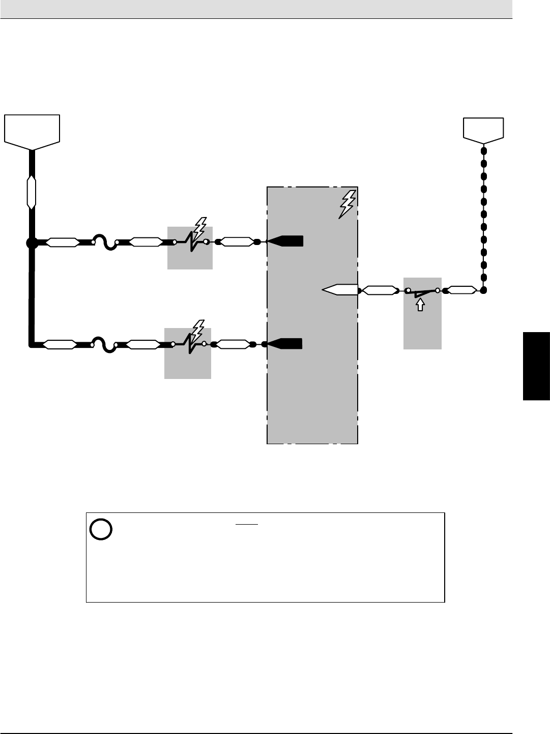
S30 SERVICE INFORMATION Electrical Troubleshooting
S30 9004086 (4--08) 83
Hopper Door Open (S30XP,S30X4)
Conditions: Key ON (RUN)
SWITCHED B+
FROM AUX. 1
RELAY (M2)
19/WHT
BATTERY
NEGATIVE
13/BLK
i-- The Enable Valve (SV4) is ON ONLY during the following Hopper related functions:
1) Hopper Lift
2) Hopper Lower
3) Hopper Door Open
4) Hopper Door Close
-- Lifting the Hopper or closing the Hopper Door turns OFF all sweeping related
functions when the One--Step system is ON.
-- Hopper Door automatically opens when activating the One--Step sweeping system.
SV4
ENABLE
VALVE
39/WHT
CONTROL BOARD
P1--4
40/TAN
44/YEL
P1--27
F5
15A
19/WHT
HOPPER
VALVE
SV5
DOOR OPEN
P1--7
33/ORA 35/GRN
NOTE: Switch closes only when
in the fully lowered position
F6
15A
19/WHT
SW16
POSITION
HOPPER
SWITCH
(Hopper
Lowered)
E
Home
Find...
Go To..
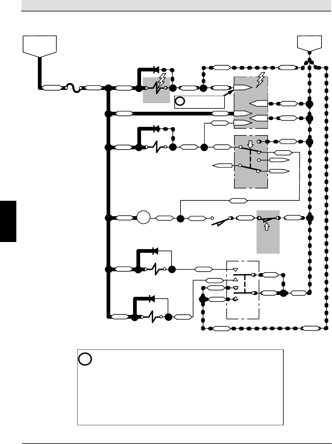
Electrical Troubleshooting S30 SERVICE INFORMATION
S30 9004086 (4--08)
84
Hopper Door Close -- Automatic (S30)
SV4
SWITCHED B+
FROM AUX. 1
RELAY (M2)
F6
15A
19/WHT
D15
ENABLE
MAIN BRUSH
RELAY
36/BLU
VALVE
36/BLU
SV5
D12
HOPPER
VALVE
DOOR OPEN
SV6A
D13
HOPPER
LIFT VALVE
SV6B
D14
HOPPER
VALVE
LOWER
SW22
2
56
4
8
13/BLK13/BLK
13/BLK
(OFF)
36/BLU
36/BLU
36/BLU
36/BLU
SW3
SWITCH
HOPPER
DOOR
(Automatic)
ENABLE VALVE
TIMER
TMR1
PIN 5
PIN 2
36/BLU
37/PUR
PIN 3
PIN 1 13/BLK
13/BLK
13/BLK
40/TAN 40/TAN
40/TAN
40/TAN
40/TAN
40/TAN
40/TAN
1
2
6
4
5
8
36/BLU
UNUSED
UNUSED
UNUSED
48/GRY
48/GRY
1
SWITCH
LIFT/LOWER
HOPPER
Conditions: Key ON (RUN), Main Brush Raised, Hopper Down
LEVER SWITCH
SW16
POSITION
HOPPER
SWITCH
68/GRY
(Hopper
Lowered)
13/BLK
M4 49/WHT
49/WHT
49/WHT
49/WHT
ENABLE
35/GRN 35/GRN
35/GRN PIN 4
40/TAN
BATTERY
NEGATIVE
i-- The Hopper Door Switch (SW3) is a 2--position switch. This drawing shows the
switch in the Automatic Door position, which automatically opens the Hopper
Door when sweeping, and closes it when the sweeping function is turned OFF.
-- Enable Valve (SV4) must be energized when Lifting or Lowering the Hopper, or
when Opening or Closing the Hopper Door. To open the Hopper Door, the Enable
Valve (SV4) and the Hopper Door Open Valve (SV5) must be energized. To close
the Hopper Door, ONLY the Enable Valve (SV4) must be energized (SV5 is OFF).
-- The Enable Valve Timer (TMR1) energizes the Enable Valve (SV4) for 6 seconds
when triggered. Triggering of TMR1 occurs when the Hopper Door Open Valve
(SV5) is turned ON or OFF, and is input on Pin 4 of TMR1.
SW5
MAIN BRUSH
(Brush Raised)
Six second battery
negative output
on Pin 5.
i
E
Home
Find...
Go To..
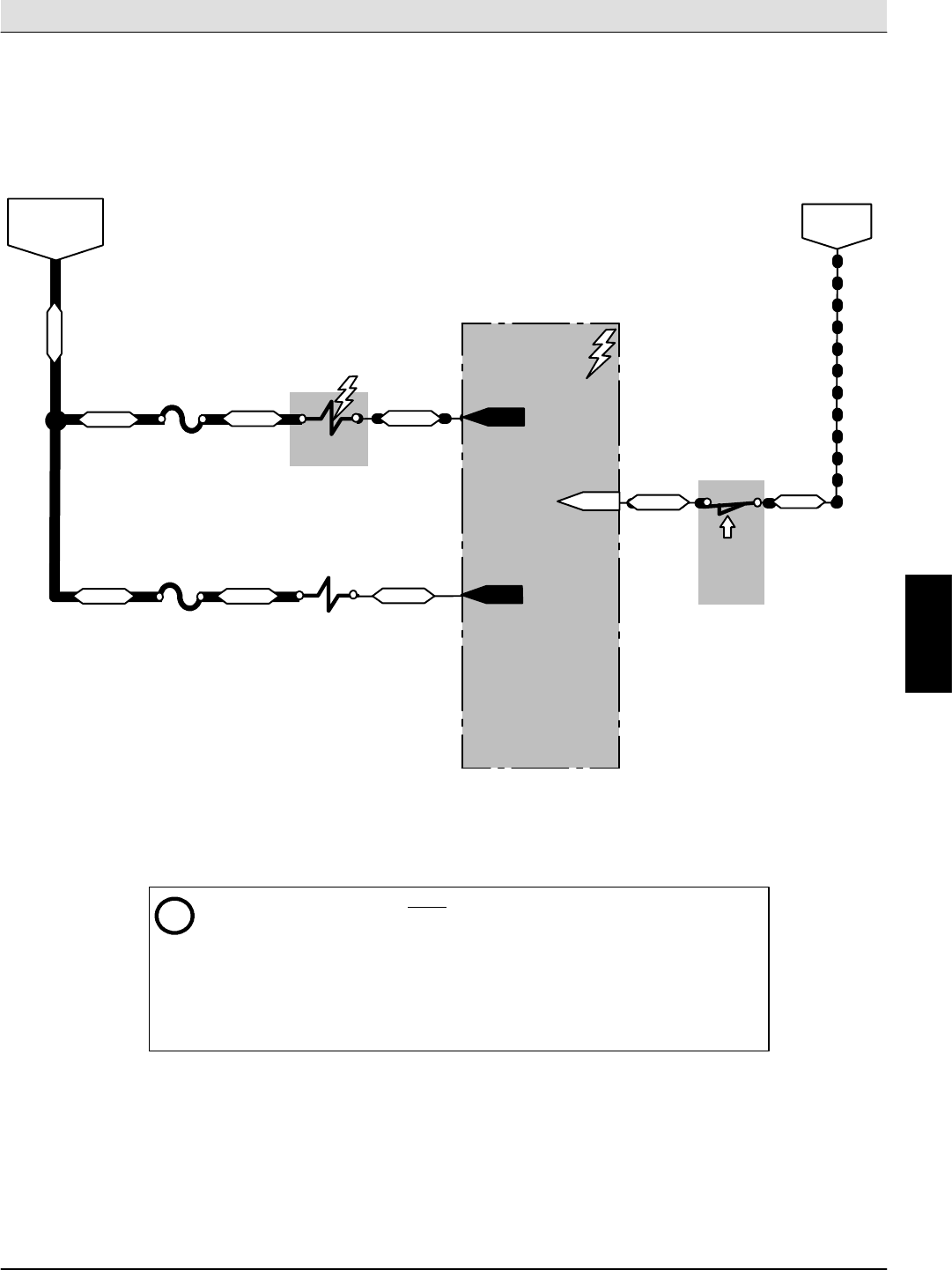
S30 SERVICE INFORMATION Electrical Troubleshooting
S30 9004086 (4--08) 85
Hopper Door Close (S30XP,S30X4)
Conditions: Key ON (RUN)
SWITCHED B+
FROM AUX. 1
RELAY (M2)
19/WHT
BATTERY
NEGATIVE
13/BLK
i-- The Enable Valve (SV4) is ON ONLY during the following Hopper related functions:
1) Hopper Lift
2) Hopper Lower
3) Hopper Door Open
4) Hopper Door Close
-- Lifting the Hopper or closing the Hopper Door turns OFF all sweeping related
functions when the One--Step system is ON.
-- Hopper Door automatically closes when deactivating the One--Step sweeping
system.
SV4
ENABLE
VALVE
39/WHT
CONTROL BOARD
P1--4
40/TAN
44/YEL
P1--27
F5
15A
19/WHT
HOPPER
VALVE
SV5
DOOR OPEN
P1--7
33/ORA 35/GRN
NOTE: Switch closes only when
in the fully lowered position
F6
15A
19/WHT
SW16
POSITION
HOPPER
SWITCH
(Hopper
Lowered)
E
Home
Find...
Go To..
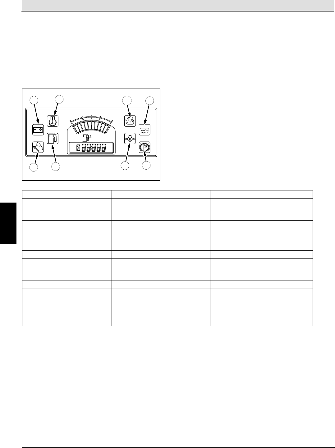
Electrical Troubleshooting S30 SERVICE INFORMATION
S30 9004086 (4--08)
86
Display Module Fault Indicators (S30)
The fault indicator lights illuminate when a fault has
occurred. Stop the machine immediately and correct
the problem if these indicators come on.
Refer to the table below to determine the cause and
remedy for the fault.
2
3
1
45
7
8
6
Fault Indicators Cause(s) Remedy
1: Water Temperature (Red) Engine coolant is too hot to safely
operate the machine
Shut off machine.
Contact TENNANT service
representative.
2: Charging System (Amber) Alternator is not charging the
battery.
Shut off machine.
Contact TENNANT service
representative.
3: Maintenance (Amber) Not Used Not Used
4: Fuel Level (Red) Fuel level is low. Refuel / Change fuel tank
5: Engine Oil Pressure (Red) Oil pressure is below the normal
operating pressure
Shut off machine.
Contact TENNANT service
representative.
6: Parking Brake (Amber) Not Used Not Used
7: Clogged Dust Filter (Amber) Dust filter is clogged Activate the filter shaker.
8: Hopper Fire (Red) Fire in the hopper Shut off machine.
Extinguish fire.
If necessary, call emergency
personnel.
E
Home
Find...
Go To..
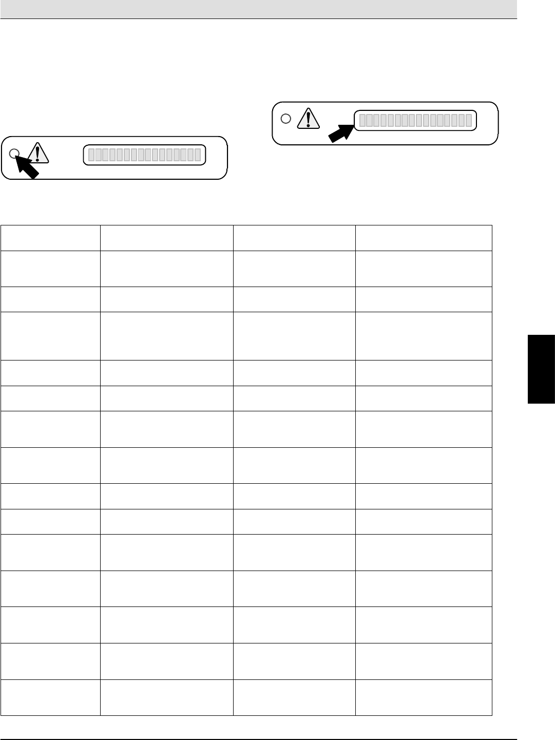
S30 SERVICE INFORMATION Electrical Troubleshooting
S30 9004086 (4--08) 87
Fault Indicators (S30XP,S30X4)
This machine is equipped with two visual indicators, a
red indicator light and an LCD (liquid crystal display).
The red indicator light will blink continuously indicating
that a fault has occurred.
The LCD will display a fault code. If there is more
than one fault, each fault will alternately display.
All faults are also accompanied by an audible alarm to
alert the operator a fault has occurred.
Refer to the table below to determine the cause and
remedy for the fault.
Fault Code
(Displayed in LCD)
Cause(s) Result Remedy
F3: CLOGGED
HYD FILTER
Hydraulic filter is clogged -- Shut off machine.
Contact TENNANT service
representative.
F4: SHAKER
FILTER
Hopper dust filter is
clogged
-- Activate filter shaker to
unclog hopper dust filter.
F5: HOPPER FIRE Fire in the hopper Terminates sweeping
functions and closes
hopper door
Shut off machine.
Extinguish fire.
If necessary, call
emergency personnel.
F6: ALTERNATOR Alternator not charging Contact TENNANT service
representative.
F7: LOW OIL
PRESS
Engine oil pressure is low Shuts down engine Contact TENNANT service
representative.
F8: HIGH ENG
TEMP
Engine temperature is high Shuts down engine Shut off machine.
Contact TENNANT service
representative.
F9: HIGH HYD
TEMP
Hydraulic fluid temperature
is high
Cancels 1--Step sweep
functions
Shut off machine.
Contact TENNANT service
representative.
F10: LOW FUEL Low fuel -- Fill fuel tank (gasoline).
Replace fuel tank (LPG).
F18: HOPPER UP Hopper is up Terminates sweeping
functions--
Lower hopper completely.
F20: UP KEY ERR Hopper up button failure Prevents all panel
operations
Shut off machine.
Contact TENNANT service
representative.
F21: DN KEY ERR Hopper down button failure Prevents all panel
operations
Shut off machine.
Contact TENNANT service
representative.
F22: OPN KEY
ERR
Hopper door open button
failure
Prevents all panel
operations
Shut off machine.
Contact TENNANT service
representative.
F23: CL KEY ERR Hopper door close button
failure
Prevents all panel
operations
Shut off machine.
Contact TENNANT service
representative.
F24: SEAT
SWITCH (Option)
Operator not in the seat
while engine is running and
parking brake not engaged
Engine will shut off Engage parking brake
before leaving the machine.
E
Home
Find...
Go To..
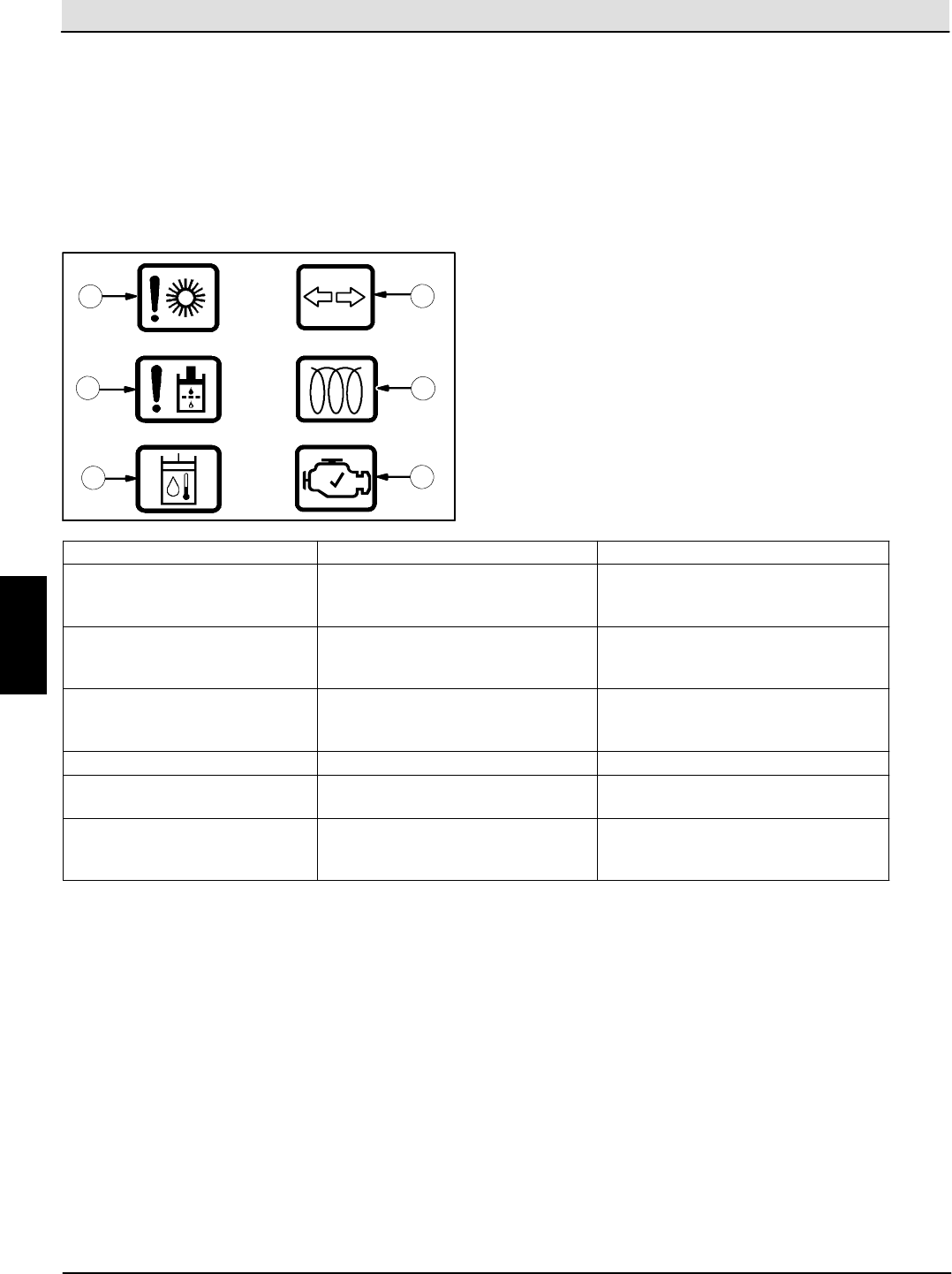
Electrical Troubleshooting S30 SERVICE INFORMATION
S30 9004086 (4--08)
88
Dash Fault Indicators (S30,S30XP,S30X4)
The dash fault indicators illuminate when a fault has
occurred. Stop the machine immediately and correct
the problem if these indicators come on.
Refer to the table below to determine the cause and
remedy for the fault.
1
2
3
4
5
6
Warning Light Cause(s) Remedy
1: Stalled Brush One of the brushes is stalled Shut off machine and remove
obstructions preventing brushes
from operating
2: Hydraulic Filter Hydraulic filter is clogged Shut off machine.
Contact TENNANT service
representative
3: Hydraulic Temperature Hydraulic system is too hot to
safely operate the machine
Shut off machine.
Contact TENNANT service
representative
4: Hazard Flasher Not Used Not Used
5: Glow Plug -- Preheat
(Diesel machines only)
Not Used Not Used
6: Check Engine Engine control system detects a
fault during machine operation
Shut off machine.
Contact TENNANT service
representative
E
Home
Find...
Go To..
S30 SERVICE INFORMATION Electrical Troubleshooting
S30 9004086 (4--08) 89
Operating, Maintenance, & Diagnostic Modes (S30XP,S30X4)
(page 1 of 2)
In addition to normal operation, the S30XP/S30X4 has five modes that can be accessed. The five modes are:
1) Input Display Mode
2) Manual Mode
3) Reset Hourmeter
4) LED Brightness Adjustment Mode
5) Self Test / Display Error Mode
During normal operation, the control panel will show the following items after turning the key switch ON:
1) The first 8 segments on the LCD display turn ON and the control panel LED’s illuminate briefly
2) The software revision date for 1 to 2 seconds
3) Fuel level and hourmeter
4) Condition and Fault messages when sensed
INPUT DISPLAY MODE
This mode allows the technician to observe if the inputs to the control board are operating as intended. Use
this mode to test or troubleshoot the input switches, wiring, and circuit board logic. Refer to the chart after the
following instructions for LED / Input associations.
To enter Input Display Mode:
1) Hold the “Side Brush” and the “4/5” panel buttons while turning ON the key switch. The key switch
must be in the RUN position, but the engine does not have to be started.
2) Release buttons after 5 seconds. Confirm that the LCD display reads “CONFIG MODE”.
3) Use the “2/3” button to scroll through the various modes until “INPUT MODE” is displayed.
4) Press the “0/1” button to select the mode. Confirm that the LCD display reads “INPUT MODE OPR”.
5) Perform necessary tests.
6) Exit Input Display Mode by turning the key switch OFF.
Panel LED LED ON Condition LED OFF Condition Pin #
Hopper UP LED NO hopper fire Hopper fire sensed P1--13
Vacuum Fan LED Low oil pressure Oil pressure OK P1--25
Hopper DOWN LED Hopper fully lowered Hopper raised P1--27
Side Brush LED High engine temperature Engine temperature OK P1--23
Filter Shaker LED Sweep filter OK Sweep filter clogged P1--14
Hopper Door Closed LED Not used Not used x
Hopper Door Open LED Alternator NOT charging Alternator charging OK P1--16
One--Step Sweep LED Not used Not used x
MANUAL MODE
This mode allows the technician to turn ON various machine functions regardless of the status of the sensed
inputs or interlocks. For example, the main brush can be turned ON with the hopper raised.
To enter Manual Mode:
1) Hold the “Side Brush” and the “4/5” panel buttons while turning ON the key switch. The key switch
must be in the RUN position, but the engine does not have to be started.
2) Release buttons after 5 seconds. Confirm that the LCD display reads “CONFIG MODE”.
3) Use the “2/3” button to scroll through the various modes until “MANUAL MODE” is displayed.
4) Press the “0/1” button to select the mode. Confirm that the LCD display reads “MANUAL MODE
OPR”.
5) Perform any necessary tests or repairs.
6) Exit Manual Mode by turning the key switch OFF.
E
Home
Find...
Go To..

Electrical Troubleshooting S30 SERVICE INFORMATION
S30 9004086 (4--08)
90
Operating, Maintenance, & Diagnostic Modes (S30XP,S30X4)
(page 2 of 2)
RESET HOURMETER MODE
Contact the Tennant Warranty Department if the hourmeter needs to be reset. The Warranty Department will
determine if it is appropriate to reset the hourmeter, and will provide the steps needed to perform this function.
The Tennant Warranty Department can be contacted by calling 1--800--553--8033.
LED BRIGHTNESS ADJUSTMENT MODE
This mode allows the technician to adjust the brightness of the LED’s on the control panel.
To enter LED Brightness Adjustment Mode:
1) Hold the “Side Brush” and the “4/5” panel buttons while turning ON the key switch. The key switch
must be in the RUN position, but the engine does not have to be started.
2) Release buttons after 5 seconds. Confirm that the LCD display reads “CONFIG MODE”.
3) Use the “2/3” button to scroll through the various modes until “LED BRIGHTNESS” is displayed.
4) Press the “0/1” button to select the mode.
5) Press & hold the “8/9” button to slowly increase the control panel LED brightness. Release the button
to set the brightness level. To reduce the brightness, press & hold the “8/9” button again until the
desired brightness level is attained, then release button.
6) Exit LED Brightness Adjustment Mode by turning the key switch OFF.
SELF TEST / DISPLAY ERROR MODE
This mode allows the technician to determine the status of the electrical load on each output from the control
board. The self test takes less than one second to perform. If the control board passes the test, “OK” will be
displayed. If the panel fails the test, the pin number of the failing output(s) will be displayed. If “OPEN LOAD”
is displayed after the pin number, the self test found the output from that pin electrically open. If “SHORT
LOAD” is displayed after the pin number, the self test found the output from that pin electrically shorted to
battery positive (B+). Repair the output wires or replace the component as needed.
NOTE: P1--15 will always result in an “OPEN LOAD” error unless the Clogged Hydraulic Filter Switch (S4) is
shorted across the terminals to test the output, as this is a normally open switch. Also, P1--24 will also result
in an “OPEN LOAD” since this output is not currently being used.
To enter Self Test / Display Error Mode:
1) Hold the “Side Brush” and the “4/5” panel buttons while turning ON the key switch. The key switch
must be in the RUN position, but the engine does not have to be started.
2) Release buttons after 5 seconds. Confirm that the LCD display reads “CONFIG MODE”.
3) Use the “2/3” button to scroll through the various modes until “SELF TEST” is displayed.
4) Press the “0/1” button to select the mode.
5) Using the displayed information, perform any necessary tests or repairs.
6) Exit Self Test / Display Error Mode by turning the key switch OFF.
E
Home
Find...
Go To..

S30 SERVICE INFORMATION Electrical Troubleshooting
S30 9004086 (4--08) 91
Circuit Board Pin Functions (S30XP,S30X4)
Pin # Function Active Voltage Inactive Voltage
P1--1 Chassis ground (static) B-- B--
P1--2 Power, battery positive B+ B--
P1--3 Power, battery positive B+ B--
P1--4 Output, SV4 B-- B+
P1--5 Output, SV1 & SV8 B-- B+
P1--6 Input, analog, S7 See NOTE 1 See NOTE 1
P1--7 Output, SV5 B-- B+
P1--8 Output, SV6A B-- B+
P1--9 Output, SV6B B-- B+
P1--10 Output, SV2 B-- B+
P1--11 Output, M3 B-- B+
P1--12 Not Used x x
P1--13 Input, digital, S14 B-- 5VDC
P1--14 Input, digital, S8 B-- 5VDC
P1--15 Output, LP11 B-- B+
P1--16 Input, digital, Alternator B-- 5VDC
P1--17 Not Used x x
P1--18 Not Used x x
P1--19 Output, LP12 B-- B+
P1--20 Output, Governor OPEN B+
P1--21 Output, Governor OPEN B+
P1--22 Ground, battery negative B-- B--
P1--23 Input, analog, S10 See NOTE 2 See NOTE 2
P1--24 Not Used x x
P1--25 Input, digital, S11 B-- 5VDC
P1--26 Input, digital, seat switch B-- 5VDC
P1--27 Input, digital, SW16 B-- 5VDC
P1--28 Input, analog, S2 or S3 See NOTE 3 See NOTE 3
P1--29 Input, digital, S1 B-- 5VDC
P1--30 Not Used x x
P1--31 Output, SV3 & SV7 B-- B+
P1--32 Memory storage B+ B+
P1--33 Ground, battery negative B-- B--
P1--34 Ground, battery negative B-- B--
P1--35 Ground, battery negative B-- B--
NOTE 1 -- Hydraulic Oil Temperature Sender (S7) specifications: High temperature indicated when oil is 107_C (225_F) or higher.
Temperature sender measures approximately 75 Ohms at 107_C (225_F). Resistance lessens as temperature increases.
NOTE 2 -- Engine Temperature Sender (S10) specifications: High temperature indicated when coolant is 107_C (225_F) or higher.
Temperature sender measures approximately 75 Ohms at 107_C (225_F). Resistance lessens as temperature increases.
NOTE 3 -- GASOLINE/DIESEL engines -- Fuel Sender (S2) specifications: Fuel sender measures approximately 90 Ohms with a full
fuel tank, and approximately 5 Ohms with an empty fuel tank.
LPG engines -- Fuel Switch (S3) specifications: Fuel switch is open above approximately 4.8 BAR (70 PSI), indicating
sufficient fuel, and measures approximately 0 Ohms below this pressure, indicating low fuel.
E
Home
Find...
Go To..

S30 SERVICE INFORMATION
S30 9004086 (4--08)
92
Home
Find...
Go To..

S30 SERVICE INFORMATION Hydraulic Troubleshooting
S30 9004086 (4--08) 93
HYDRAULIC
Troubleshooting Information
BEFORE CONDUCTING TESTS:
* Read and Follow ALL Safety Warnings and Precautions as mentioned
at the beginning of this manual
* Engine & Hydraulic Oil Must Be At Normal Operating Temperatures
after Running Machine and Hydraulics a Minimum of 5 Minutes
* Examine Machine For Any Linkage Binding or Mechanical Problems
DURING TESTS:
* Call Technical Services if Diagnostic Time Exceeds One Hour With
Unknown Cause or Course of Action
* Maintain Normal Main Brush Pressure as Listed in Operator’s Manual
NOTE: Troubleshooting charts may be shown with optional equipment. The optional equipment
may not be specified in these charts. Some machines may not be equipped with all components
shown.
H
Home
Find...
Go To..
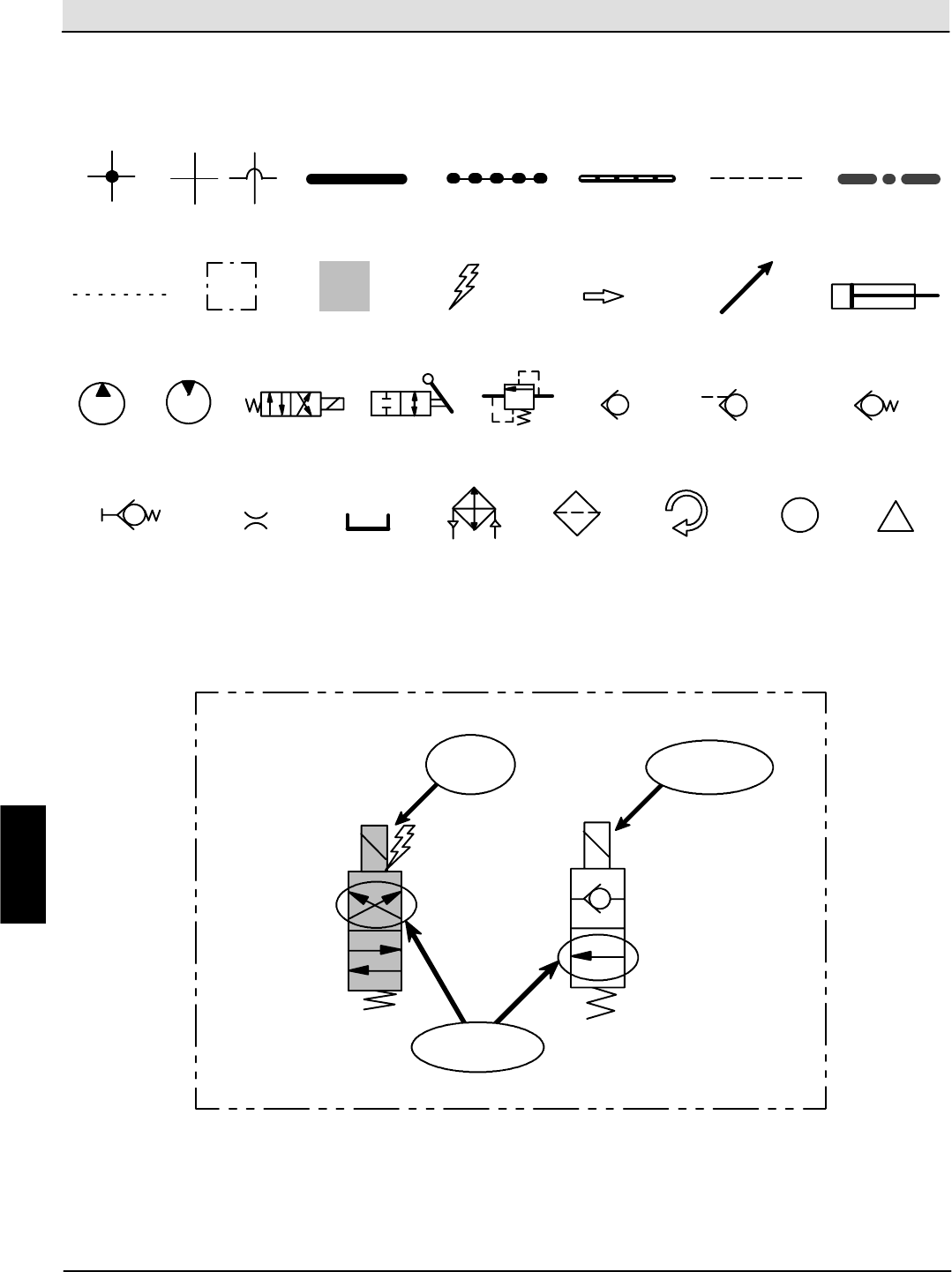
Hydraulic Troubleshooting S30 SERVICE INFORMATION
S30 9004086 (4--08)
94
General Information (S30, S30XP, S30X4)
Page1of2
Commonly Used Hydraulic Symbols
i
LINES NOT
CONNECTED
ASSEMBLY CYLINDER OR RAM
ACTIVATED
COMPONENT
ENERGIZED
COMPONENT
INFORMATION
HIGH PRESSURE
OR FLOW LINE
RETURN OR LOW
PRESSURE LINE
NON--ACTIVE
PILOT PORT LINE
!
WARNING
LINES
CONNECTED
SUCTION LINE
ACTIVE PILOT
PORT LINE
CASE DRAIN
LINE
HYDRAULIC FLOW
OR MOVEMENT
VARIABLE
OR PWM
ROTATING
COMPONENT
PUMP MOTOR SOLENOID
VALVE
MANUAL
VALVE
RELIEF
VALVE
CHECK
VALVE
PILOT PORT
CHECK VALVE
SPRING LOADED
CHECK VALVE
QUICK CONNECT
TEST PORT
RESTRICTOR
OR ORIFICE
TANK OR
RESERVOIR
OIL COOLER
OR HEAT
EXCHANGER
FILTER OR
STRAINER
Energized
Solenoid
Valve
Non--energized
Solenoid Valve
Valve position for
indicated circuit
EXAMPLES
H
Home
Find...
Go To..
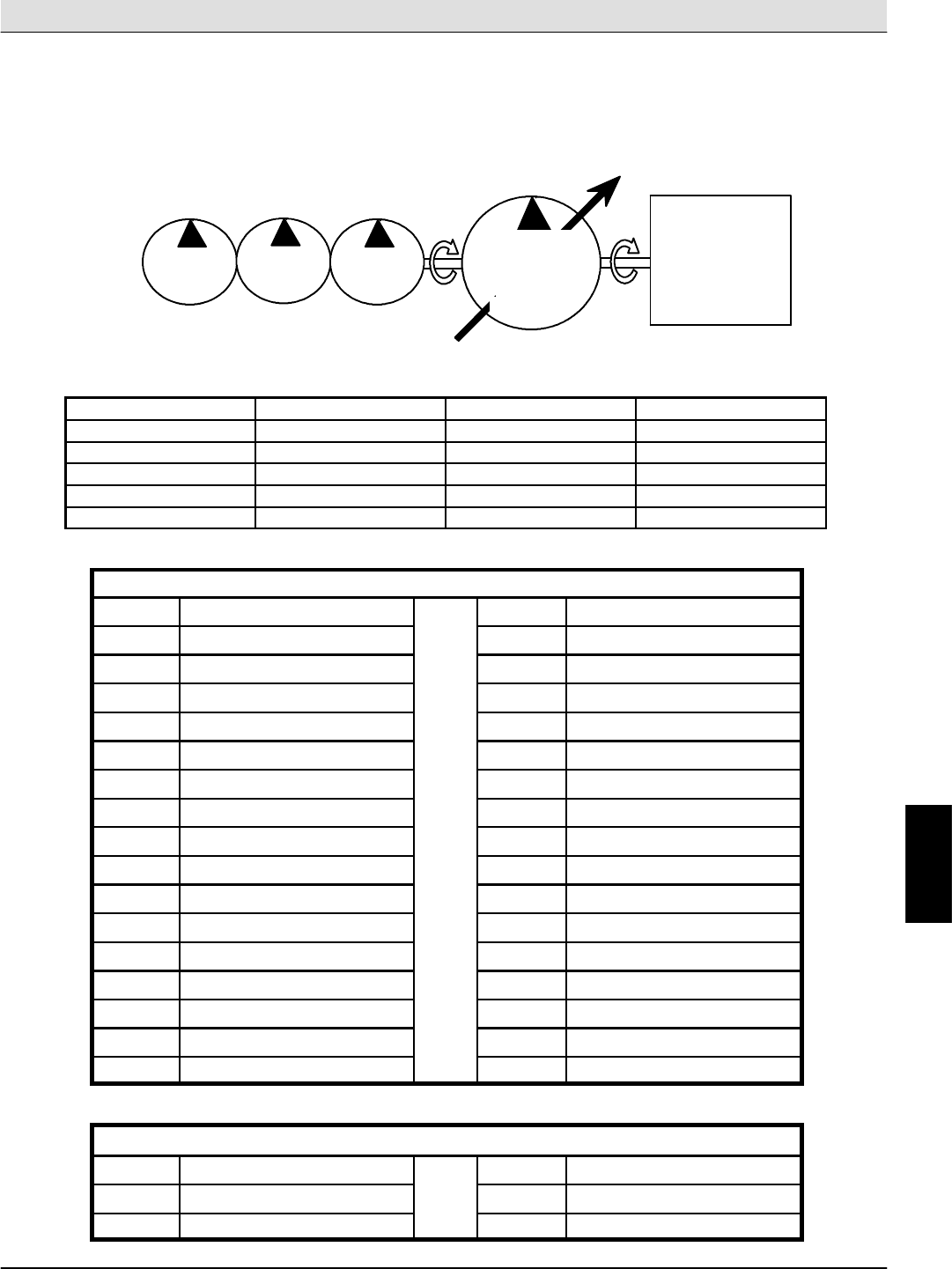
S30 SERVICE INFORMATION Hydraulic Troubleshooting
S30 9004086 (4--08) 95
General Information (S30, S30XP, S30X4)
Page2of2
Hydraulic Pump Flow Rates (typical)
PROPEL PUMP
ACCESSORY PUMPS
ENGINE
11.5 cc
per rev.
(0.7 ci)
11.5 cc
per rev.
(0.7 ci)
6.4 cc
per rev.
(0.39 ci)
PUMP
4
PUMP
3
PUMP
2
ENGINE
S30X4:
S30,S30XP:
per rev.
PUMP 1
40.6 cc (2.48 ci)
per rev.
20.3 cc (1.24 ci)
Pump Displacement Volume @ 2000RPM Volume @ 2400RPM
Pump 1 (S30, S30XP) 20.3 cc (1.24 ci) 40.5 lpm (10.7 gpm) 48.4 lpm (12.8 gpm)
Pump 1 (S30X4) 40.6 cc (2.46 ci) 81.0 lpm (21.4 gpm) 96.5 lpm (25.5 gpm)
Pump 2 11.5 cc (0.7 ci) 22.7 lpm (6.0 gpm) 27.2 lpm (7.2 gpm)
Pump 3 11.5 cc (0.7 ci) 22.7 lpm (6.0 gpm) 27.2 lpm (7.2 gpm)
Pump 4 6.4 cc (0.39 ci) 12.5 lpm (3.3 gpm)15.1 lpm (4.0 gpm)
Commonly Used Abbreviations
AUX Auxiliary MFLD Manifold
CC Cubic Centimeters MTR Motor
CK Check Valve OR Orifice
CM Centimeters PC Pilot Port Check Valve
CU Cubic PMP Pump
CV Control Valve PSI Pounds Per Square Inch
CYL Cylinder PSWITCH Pressure Switch
DC Direct Current PWM Pulse Width Modulation
DCn Disconnect (Test Port) RES Reservoir
FLTR Filter RH Right Hand
GPM Gallons Per Minute RPM Revolutions Per Minute
HTX Heat Exchanger RV Relief Valve
IN Inches SC Spring Loaded Check Valve
kPa KiloPascals STRN Strainer
LH Left Hand SV Solenoid Valve
LPM Liters Per Minute SW Switch
MMotor (Combustion) VVolts
Hydraulic Manifold Port Markings
CCylinder Connection PPump Connection
GTest Port PS Pressure Switch Connection
MMotor Connection TTank Connection
H
Home
Find...
Go To..
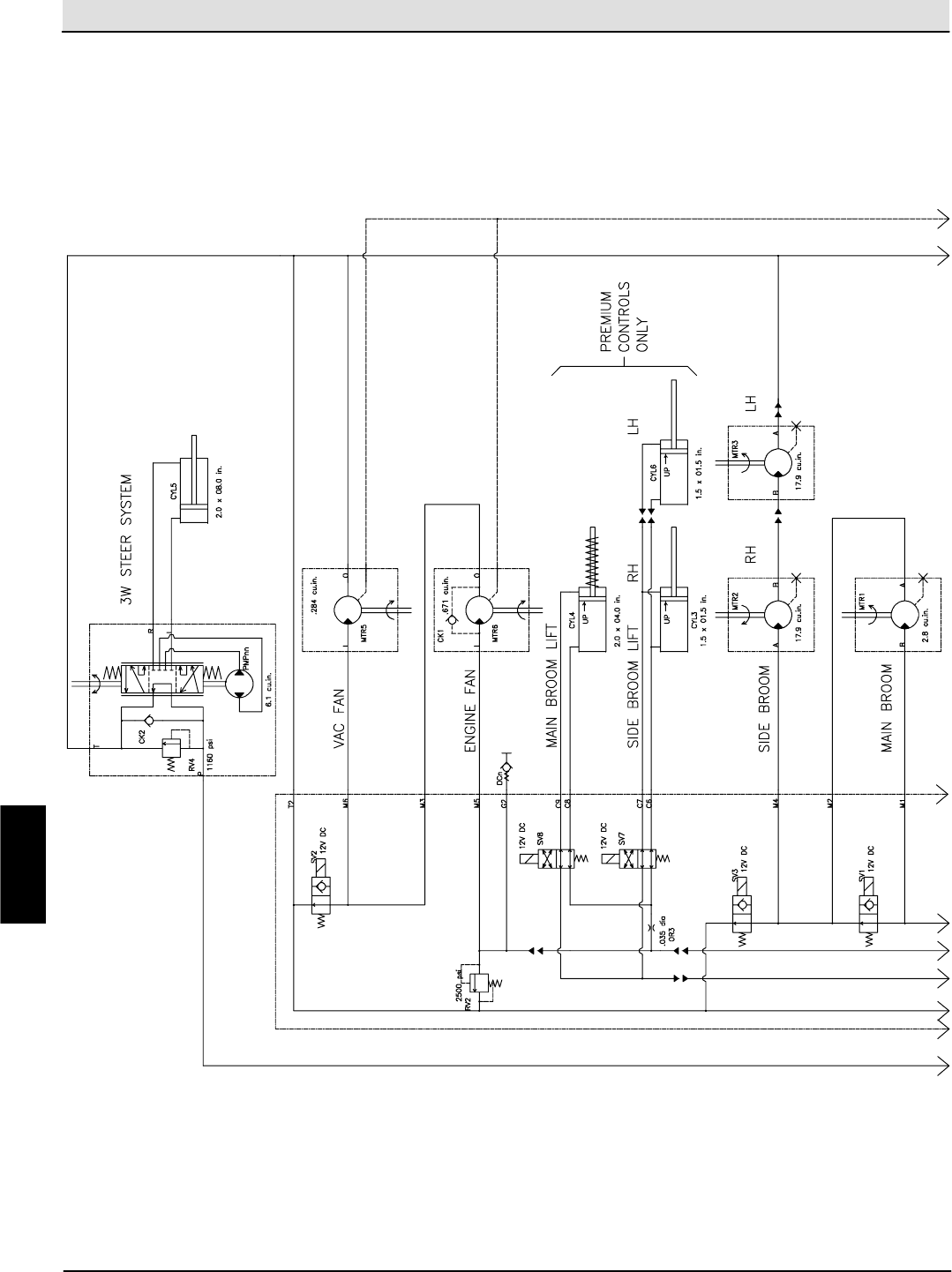
Hydraulic Troubleshooting S30 SERVICE INFORMATION
S30 9004086 (4--08)
96
Hydraulic Schematic (S30, S30XP)
(page 1 of 2)
H
Home
Find...
Go To..
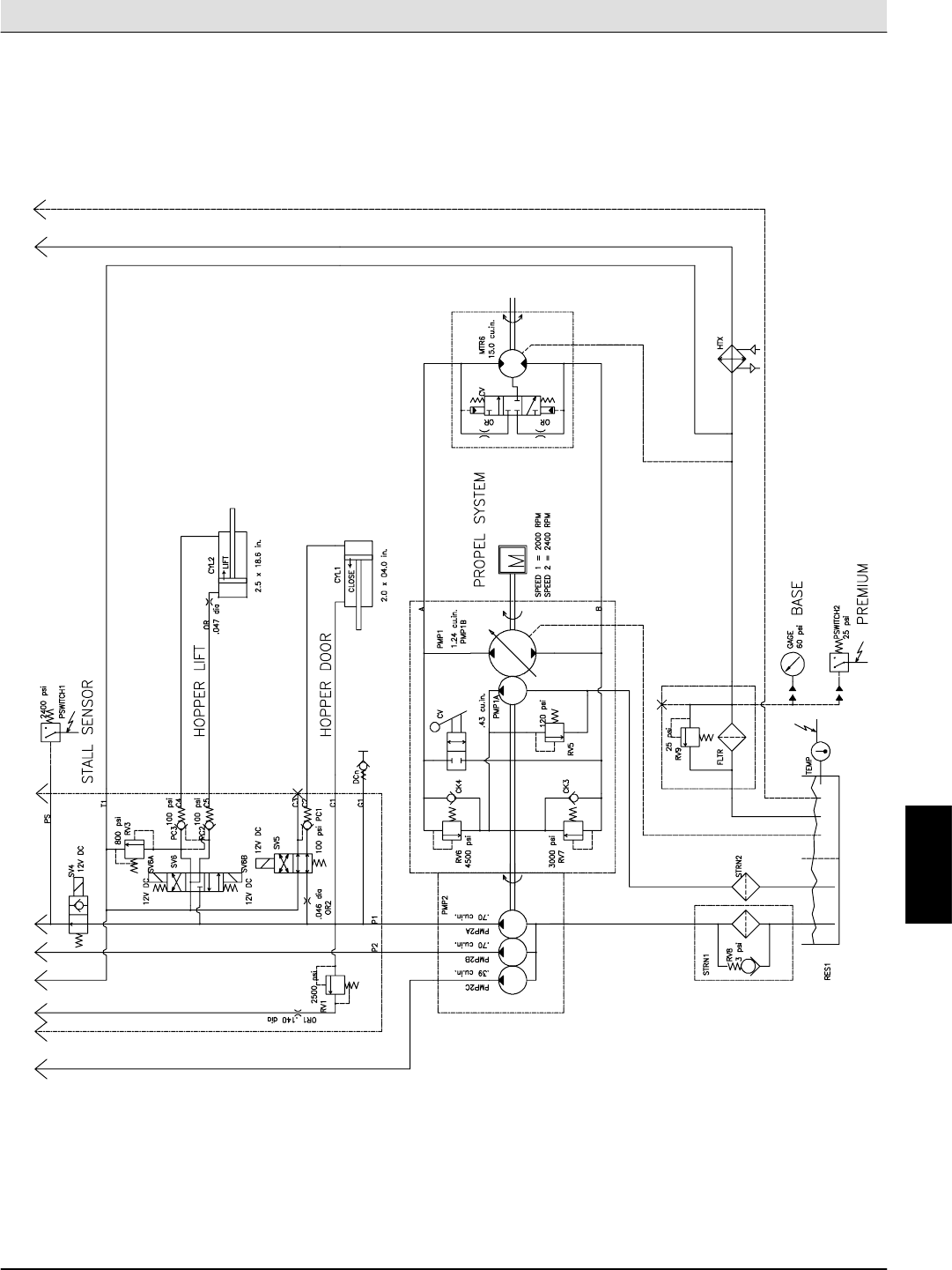
S30 SERVICE INFORMATION Hydraulic Troubleshooting
S30 9004086 (4--08) 97
Hydraulic Schematic (S30, S30XP)
(page 2 of 2)
H
Home
Find...
Go To..
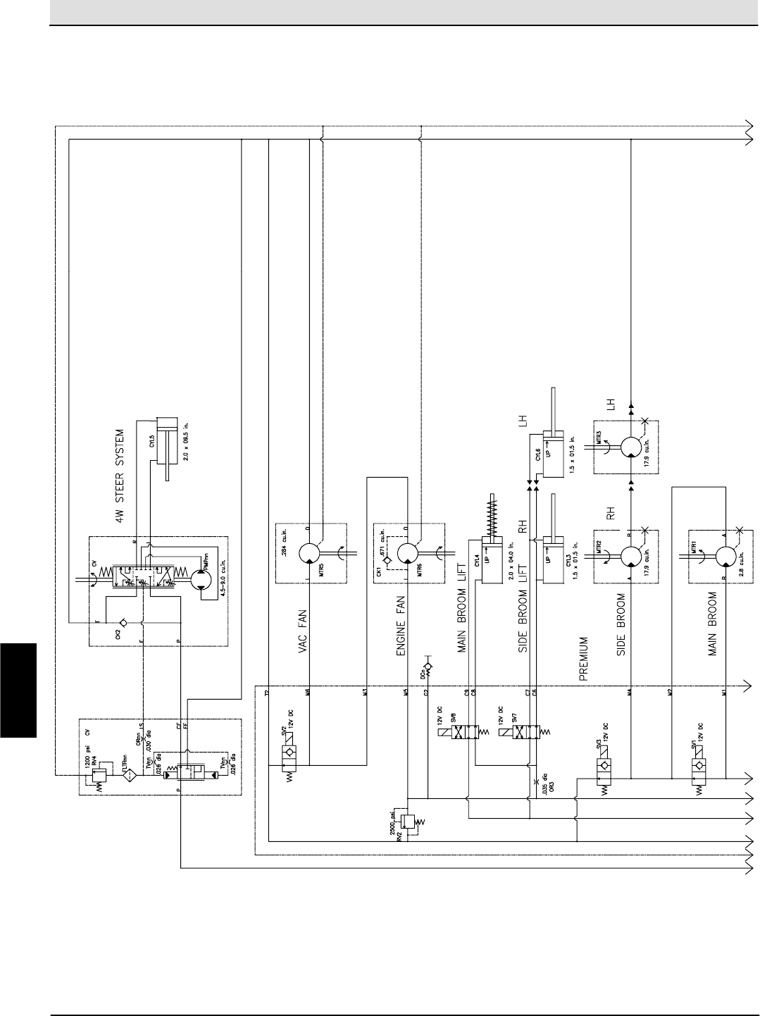
Hydraulic Troubleshooting S30 SERVICE INFORMATION
S30 9004086 (4--08)
98
Hydraulic Schematic (S30X4)
(page 1 of 2)
H
Home
Find...
Go To..
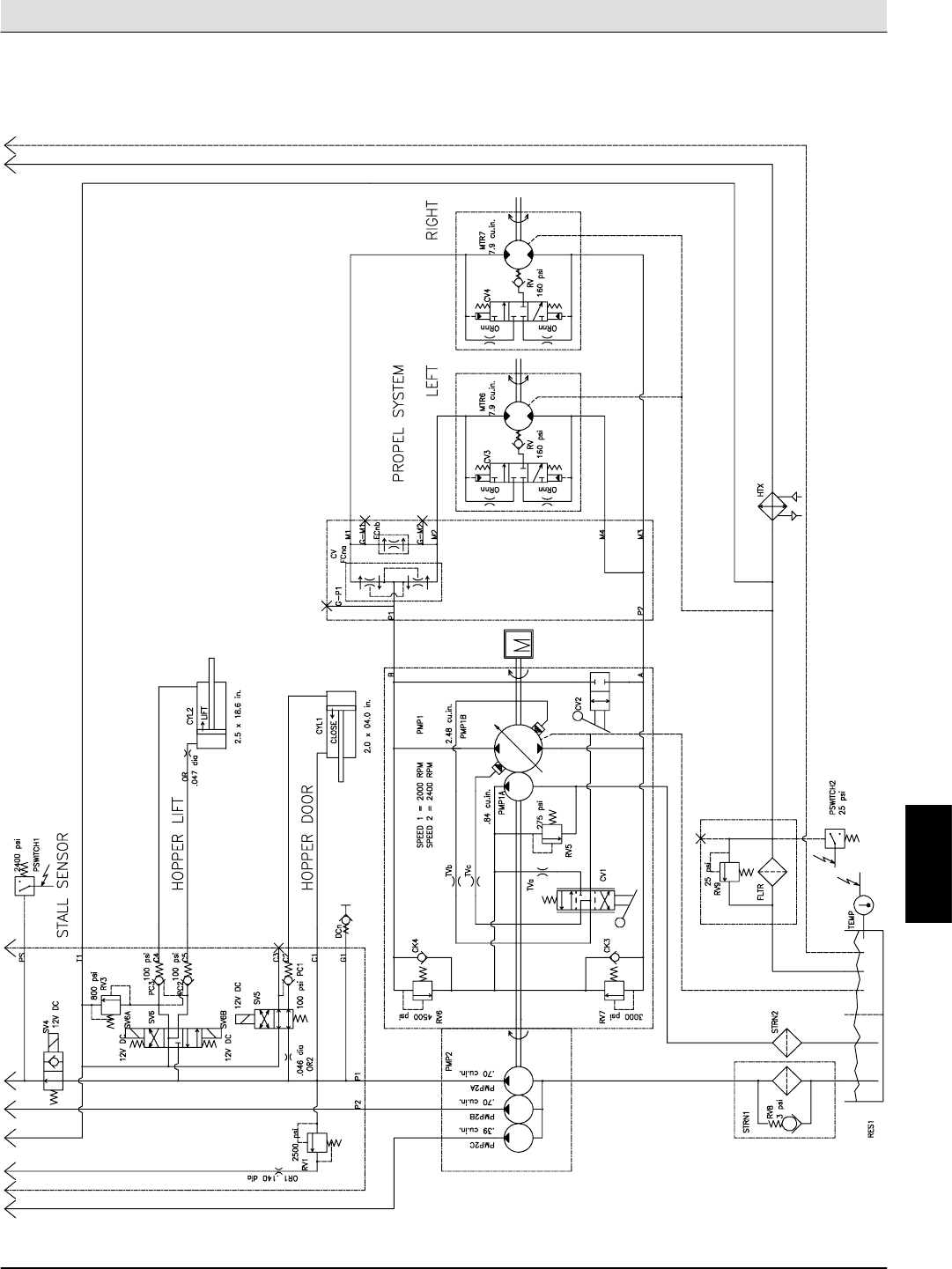
S30 SERVICE INFORMATION Hydraulic Troubleshooting
S30 9004086 (4--08) 99
Hydraulic Schematic (S30X4)
(page 2 of 2)
H
Home
Find...
Go To..
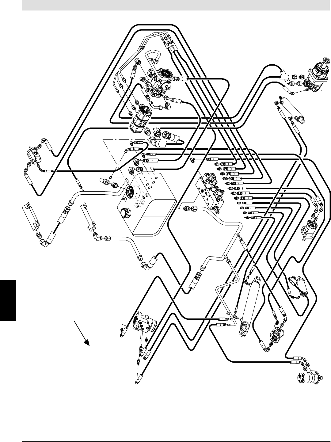
Hydraulic Troubleshooting S30 SERVICE INFORMATION
S30 9004086 (4--08)
100
Overall Hydraulic Hose Diagram (S30)
M4
C4 C5
M5
P2
C2
T1
C1
M1 M2
T2
P1
M3
M6
T
L
R
P
Cooler Cooling Fan
Motor
Aux
Pump
Propel
Pump
Reservoir
Control
Valve
Steer
Cylinder
Wheel Drive
Motor
Main Brush
Motor
Hopper
Dump Door
Cylinder
Vac Fan
Motor
Side Brush
Motor
Hopper Lift
Cylinder
Steering
Valve
FRONT
H
Home
Find...
Go To..
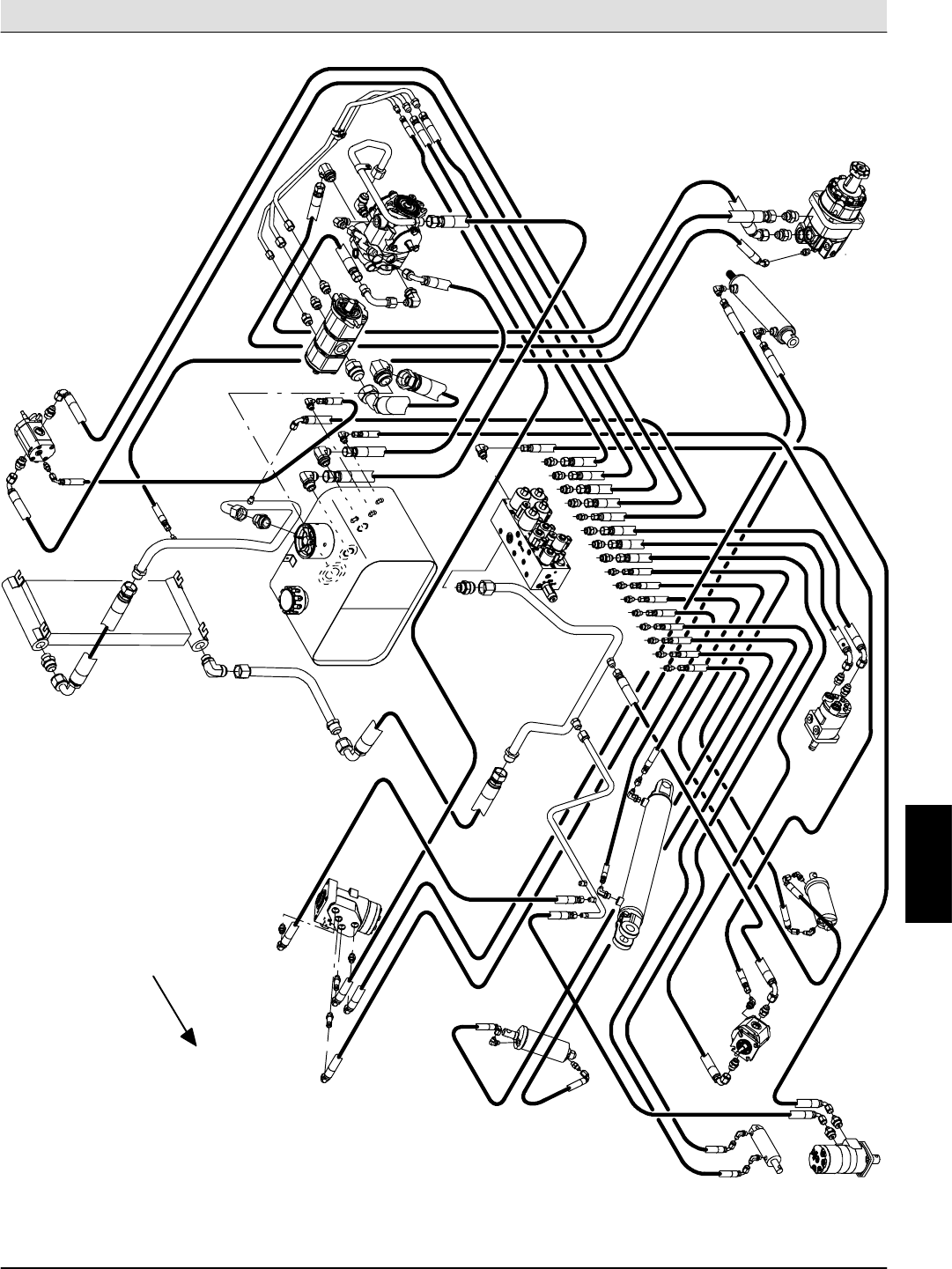
S30 SERVICE INFORMATION Hydraulic Troubleshooting
S30 9004086 (4--08) 101
Overall Hydraulic Hose Diagram (S30XP)
M4
C4 C5
M5
P2
C2
T1
C1
M1 M2
T2
P1
M6
T
L
R
P
Cooler Cooling Fan
Motor
Aux
Pump
Propel
Pump
Reservoir
Steer
Cylinder
Wheel Drive
Motor
Main Brush
Motor
Hopper
Dump Door
Cylinder
Vac Fan
Motor
Side Brush
Motor
Hopper
Lift Cylinder
Steering
Valve
Side Brush
Lift Cylinder
C8
C9
C6
C7
Main Brush
Lift Cylinder
M3
Control
Valve
FRONT
H
Home
Find...
Go To..
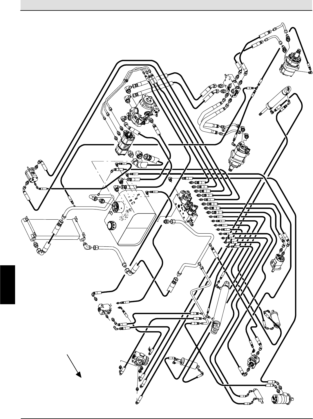
Hydraulic Troubleshooting S30 SERVICE INFORMATION
S30 9004086 (4--08)
102
Overall Hydraulic Hose Diagram (S30X4)
M4
C4 C5
M5
P2
C2
T1
C1
M1 M2
T2
P1
M6
Cooler Cooling Fan
Motor
Aux
Pump
Propel
Pump
Reservoir
Steer
Cylinder
Wheel Drive
Motor
Main Brush
Motor
Hopper
Dump Door
Cylinder
Vac Fan
Motor
Side Brush
Motor
Hopper
Lift Cylinder
Steering
Valve
Side Brush
Lift Cylinder
C8
C9
C6
C7
Main Brush
Lift Cylinder
M3
Control
Valve
T
L
RP
LS
L
P
CF EF
LS T
Priority
Steering
Valve
Wheel Drive
Motor
Flow Divider
Valve
FRONT
H
Home
Find...
Go To..
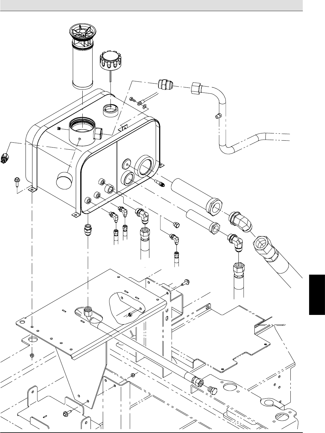
S30 SERVICE INFORMATION Hydraulic Troubleshooting
S30 9004086 (4--08) 103
Hydraulic Reservoir Hose Diagram
H
Home
Find...
Go To..
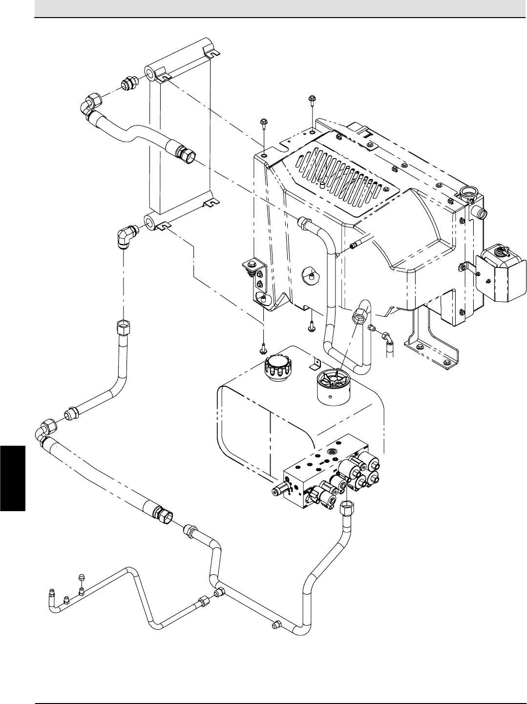
Hydraulic Troubleshooting S30 SERVICE INFORMATION
S30 9004086 (4--08)
104
Hydraulic Cooler Hose & Tube Diagram
H
Home
Find...
Go To..
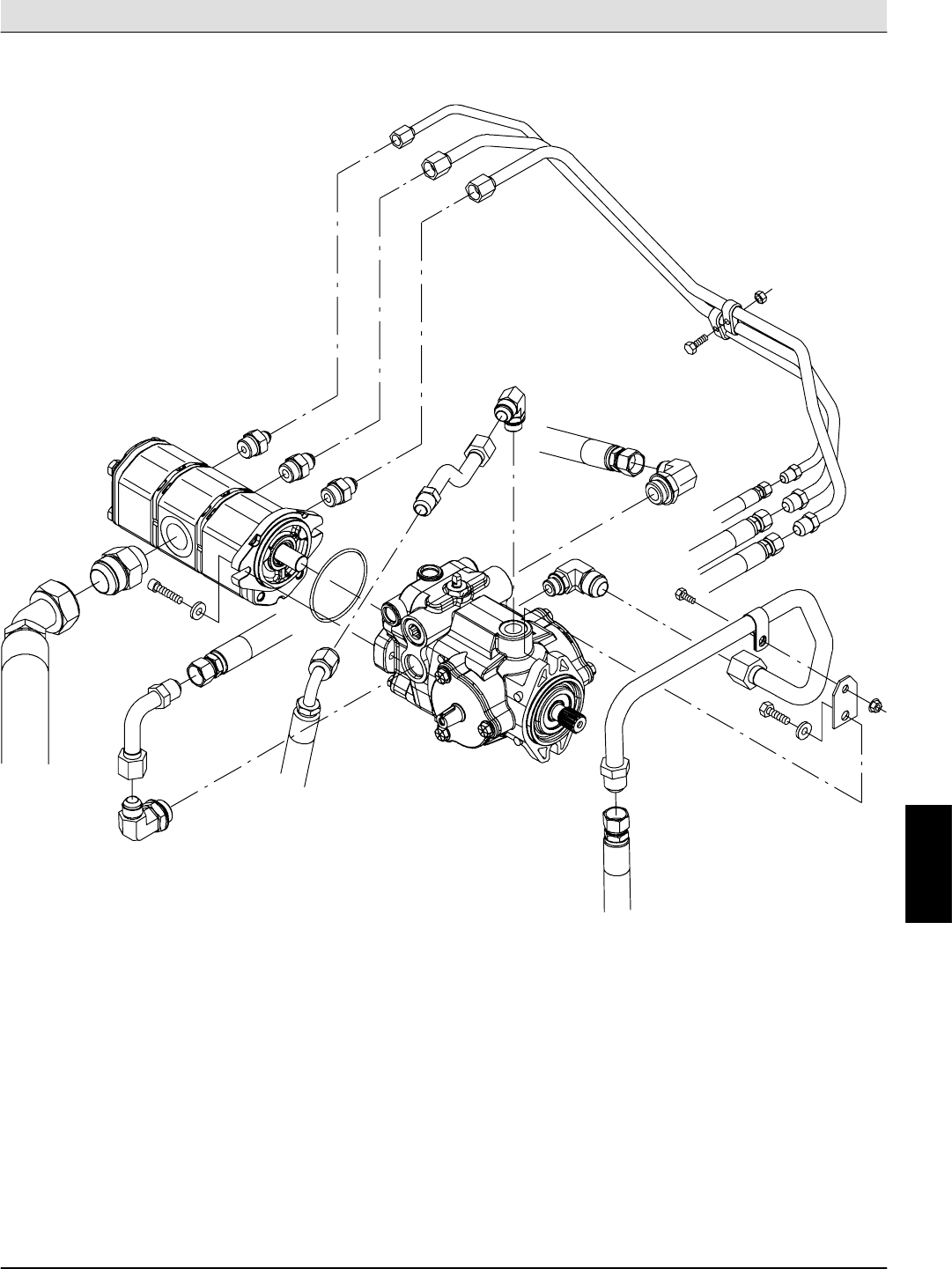
S30 SERVICE INFORMATION Hydraulic Troubleshooting
S30 9004086 (4--08) 105
Hydraulic Pumps Diagram (S30, S30XP)
H
Home
Find...
Go To..
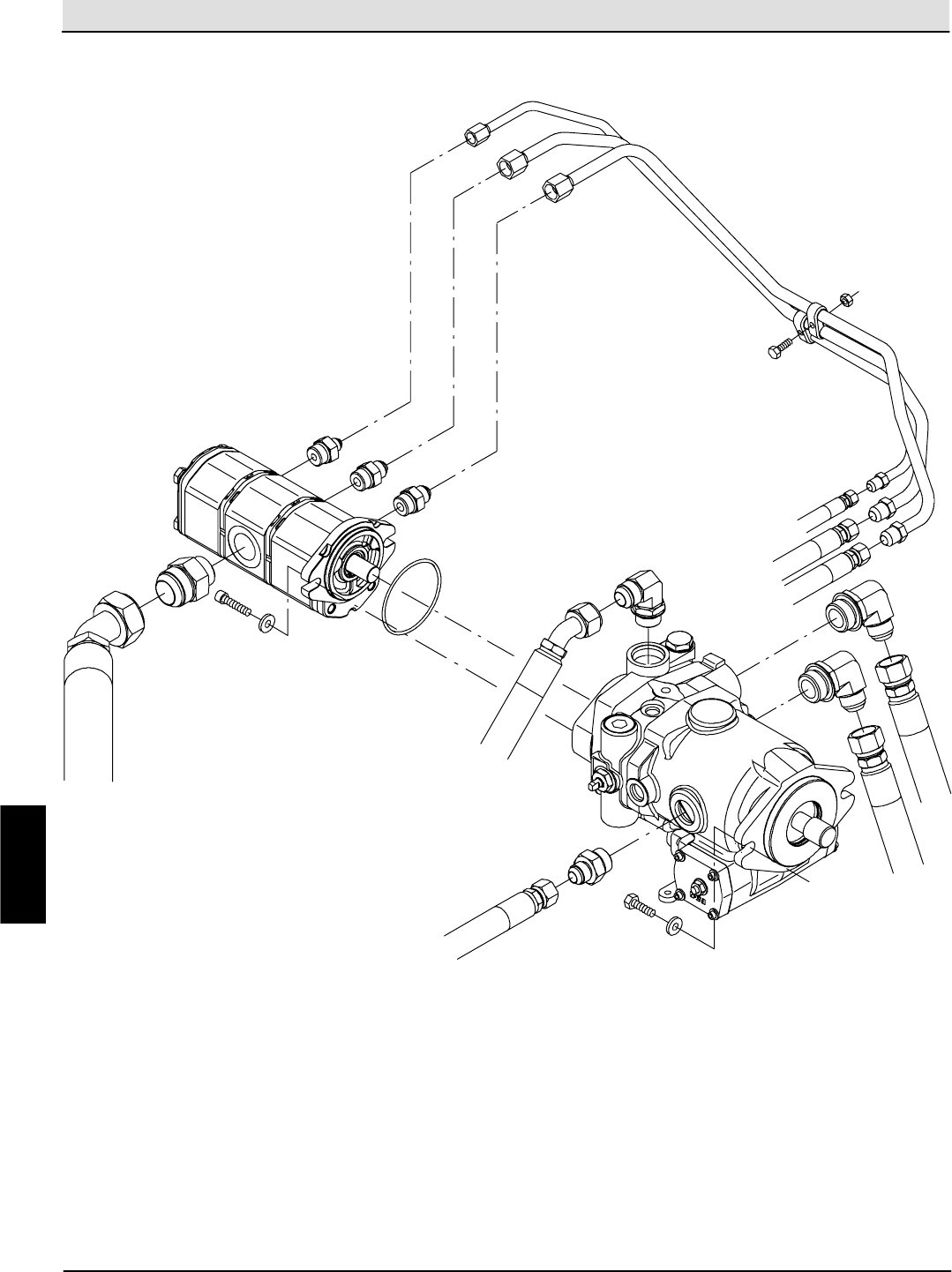
Hydraulic Troubleshooting S30 SERVICE INFORMATION
S30 9004086 (4--08)
106
Hydraulic Pumps Diagram (S30X4)
H
Home
Find...
Go To..
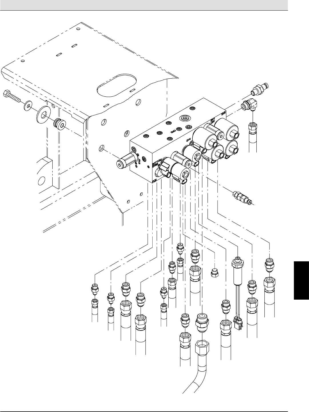
S30 SERVICE INFORMATION Hydraulic Troubleshooting
S30 9004086 (4--08) 107
Hydraulic Valve Block Diagram (S30)
M4
G2
G1
C4
C5
M5
P2 C2
T1
C1
M1
M2
T2
C3
P1
PS
M3
M6
H
Home
Find...
Go To..
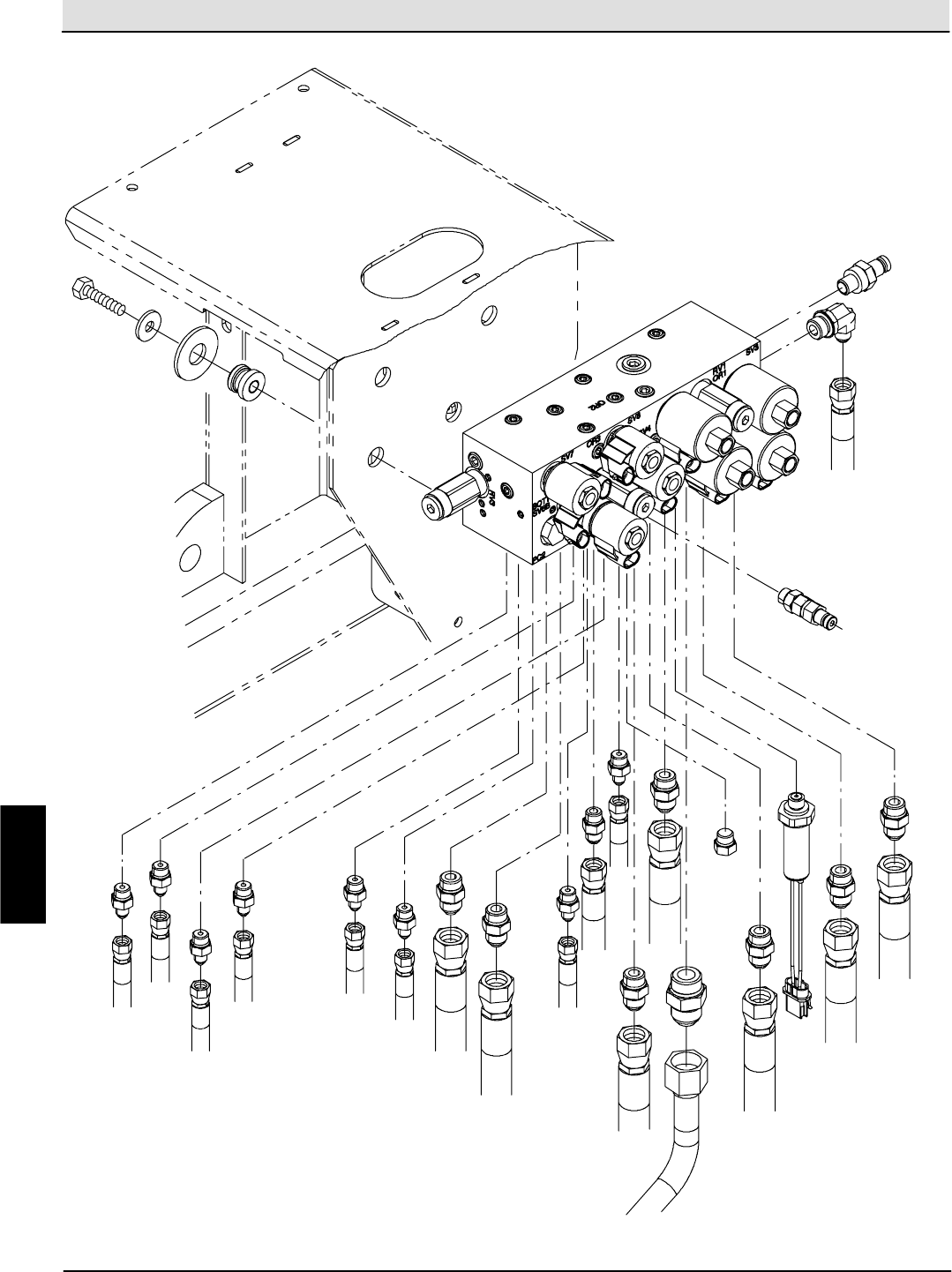
Hydraulic Troubleshooting S30 SERVICE INFORMATION
S30 9004086 (4--08)
108
Hydraulic Valve Block Diagram (S30XP, S30X4)
M4
G2
G1
C4
C5
M5
P2 C2
T1
C1
M1
M2
T2
C3
P1
PS
M3
M6
C9
C8
C7
C6
H
Home
Find...
Go To..
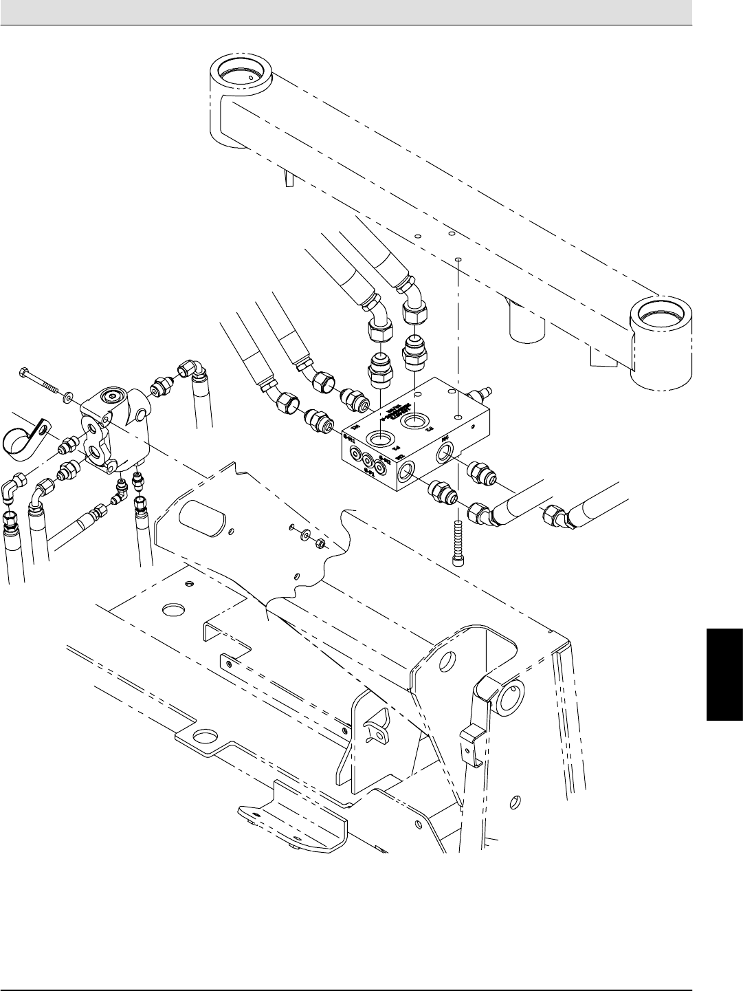
S30 SERVICE INFORMATION Hydraulic Troubleshooting
S30 9004086 (4--08) 109
Hydraulic Priority and Flow Divider Valve Diagram (S30X4)
H
Home
Find...
Go To..
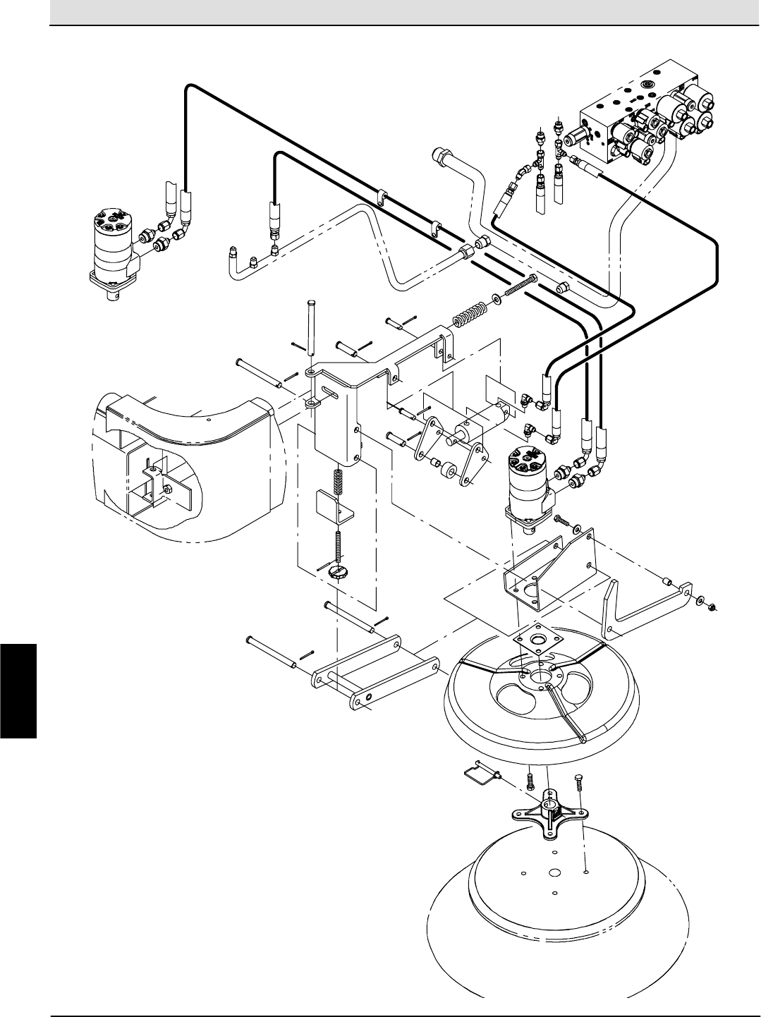
Hydraulic Troubleshooting S30 SERVICE INFORMATION
S30 9004086 (4--08)
110
Left Hand Side Brush Hydraulic Diagram (S30XP, S30X4)
C7
C6
H
Home
Find...
Go To..
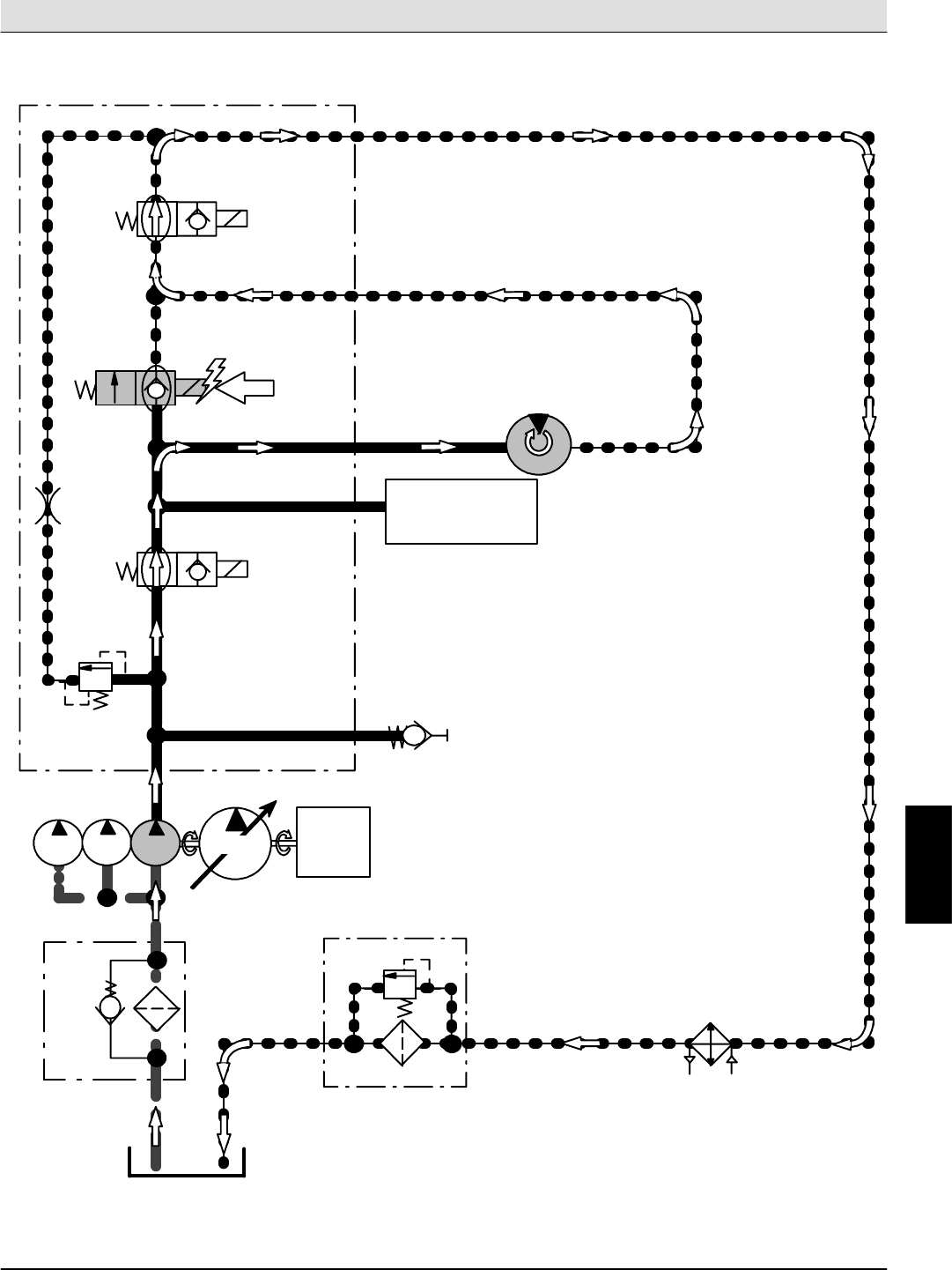
S30 SERVICE INFORMATION Hydraulic Troubleshooting
S30 9004086 (4--08) 111
Main Brush ON (S30, S30XP, S30X4)
Conditions: Engine Running, Main Brush Lowered, Hopper Down
ENGINE
PUMP
4
PUMP
3
PUMP
2PUMP
1
RES1
20.7 kPa
RV8
(3 psi)
STRN1
P1
G1
SV4
TEST
PORT
M1
OR1
172 BAR
RV1
(2500 psi)
(0.14 in)
3.5 mm PS
MAIN
BRUSH
MOTOR
STALL SENSOR
(PRESSURE SWITCH)
165 BAR
(2400 psi)
M2
T2
SV1
SV3
HTX
172 kPa
RV9
(25 psi)
FLTR
MTR1
MANIFOLD ASSEMBLY
H
Home
Find...
Go To..
i
Vacuum Fan speeds (+/- 300 RPM):
Engine @ 2000 RPM: 4600 RPM
Engine @ 2400 RPM: 5500 RPM
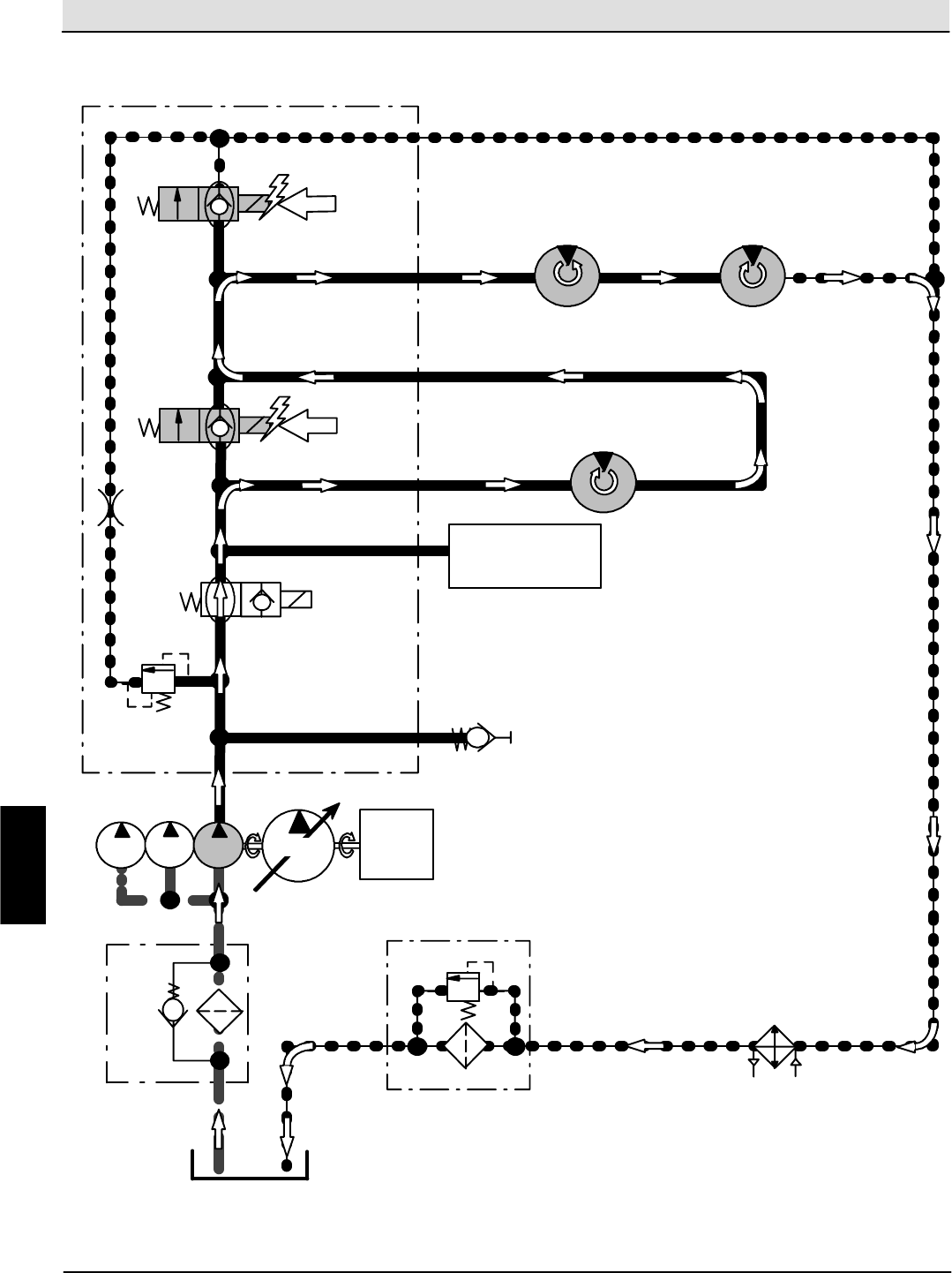
Hydraulic Troubleshooting S30 SERVICE INFORMATION
S30 9004086 (4--08)
112
Main Brush & Side Brush(es) ON (S30, S30XP, S30X4)
Conditions: Engine Running, Sweep System Activated, Side Brush(es) Lowered, Hopper Down
ENGINE
PUMP
4
PUMP
3
PUMP
2PUMP
1
RES1
20.7 kPa
RV8
(3 psi)
STRN1
P1
G1
SV4
TEST
PORT
M1
OR1
172 BAR
RV1
(2500 psi)
(0.14 in)
3.5 mm
PS
MAIN
BRUSH
MOTOR
STALL SENSOR
(PRESSURE SWITCH)
165 BAR
(2400 psi)
M2
T2
SV1
HTX
172 kPa
RV9
(25 psi)
FLTR
SV3
RIGHT SIDE
BRUSH MOTOR
LEFT SIDE
BRUSH MOTOR
M4
MTR1
MTR2 MTR3
MANIFOLD ASSEMBLY
H
Home
Find...
Go To..
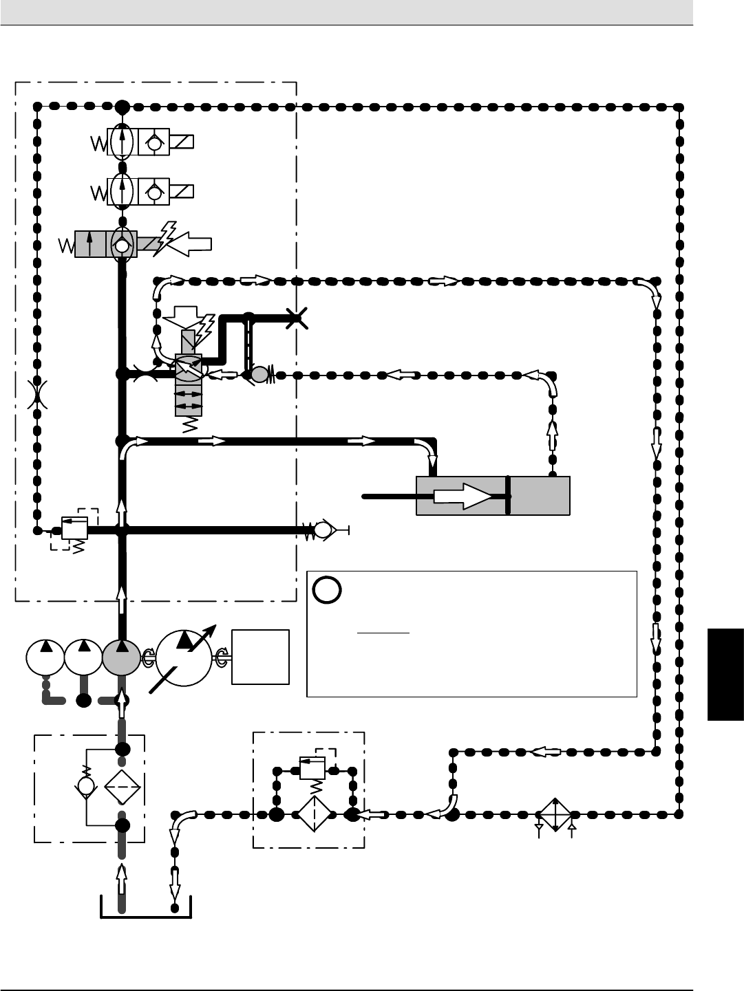
S30 SERVICE INFORMATION Hydraulic Troubleshooting
S30 9004086 (4--08) 113
Hopper Door Open (S30, S30XP, S30X4)
Conditions: Engine Running, Hopper Door Switch in OPEN Position
ENGINE
PUMP
4
PUMP
3
PUMP
2PUMP
1
RES1
20.7 kPa
RV8
(3 psi)
STRN1
P1
G1
SV4
TEST
PORT
OR1
172 BAR
RV1
(2500 psi)
(0.14 in)
3.5 mm
T2
SV1
HTX
172 kPa
RV9
(25 psi)
FLTR
SV3
SV5
C2
C3
T1
3.5 mm
OR1
(0.14 in)
SV1
HTX
172 kPa
RV9
(25 psi)
FLTR
SV3
HOPPER DOOR CYLINDER
C1
SV5
OR2
(0.46 in)
11.7 mm
OPEN CYL1
i-- When Hopper Door Cylinder reaches the end of
travel, Relief Valve (RV1) will open to prevent
excessive pressure build--up.
-- S 3 0 O N L Y : The Enable Valve Timer (TMR1) energizes
the Enable Valve (SV4) for 6 seconds when triggered.
Triggering of TMR1 occurs when the Hopper Door Open
Valve (SV5) is turned ON or OFF, and is input on Pin 4 of
TMR1.
PC1
6.9 BAR
(100 psi)
MANIFOLD ASSEMBLY
H
Home
Find...
Go To..
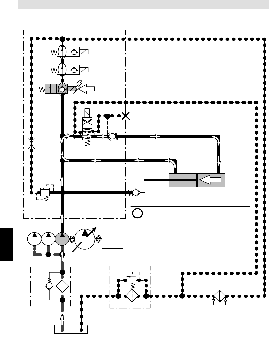
Hydraulic Troubleshooting S30 SERVICE INFORMATION
S30 9004086 (4--08)
114
Hopper Door Close (S30, S30XP, S30X4)
Conditions: Engine Running, Main Brush Raised, Hopper Door Switch in CLOSE or AUTO Position
ENGINE
PUMP
4
PUMP
3
PUMP
2PUMP
1
RES1
20.7 kPa
RV8
(3 psi)
STRN1
P1
G1
SV4
TEST
PORT
OR1
172 BAR
RV1
(2500 psi)
(0.14 in)
3.5 mm
T2
SV1
HTX
172 kPa
RV9
(25 psi)
FLTR
SV3
C2
C3
T1
3.5 mm
OR1
(0.14 in)
SV1
HTX
172 kPa
RV9
(25 psi)
FLTR
SV3
HOPPER DOOR CYLINDER
C1
OR2
(0.46 in)
11.7 mm
CLOSE
CYL1
i-- Surface area differential in hydraulic cylinder
causes Hopper Door Cylinder to extend
-- When Hopper Door Cylinder reaches the end of
travel, Relief Valve (RV1) will open to prevent
excessive pressure build--up.
-- S 3 0 O N L Y : The Enable Valve Timer (TMR1) energizes
the Enable Valve (SV4) for 6 seconds when triggered.
Triggering of TMR1 occurs when the Hopper Door Open
Valve (SV5) is turned ON or OFF, and is input on Pin 4 of
TMR1.
SV5
PC1
6.9 BAR
(100 psi)
MANIFOLD ASSEMBLY
H
Home
Find...
Go To..
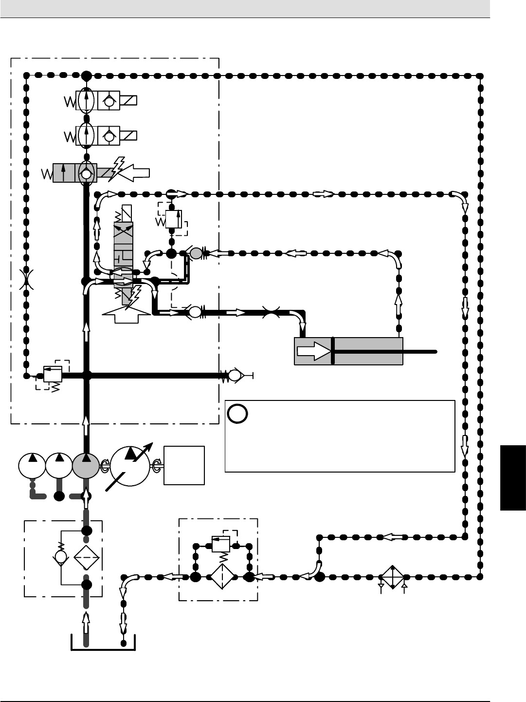
S30 SERVICE INFORMATION Hydraulic Troubleshooting
S30 9004086 (4--08) 115
Hopper Lift (S30, S30XP, S30X4)
Conditions: Engine Running, Hopper Lift Switch in RAISE Position
ENGINE
PUMP
4
PUMP
3
PUMP
2PUMP
1
RES1
20.7 kPa
RV8
(3 psi)
STRN1
P1
G1
SV4
TEST
PORT
OR1
172 BAR
RV1
(2500 psi)
(0.14 in)
3.5 mm
T2
SV1
HTX
172 kPa
RV9
(25 psi)
FLTR
SV3
C4
T1
3.5 mm
OR1
SV1
HTX
172 kPa
RV9
(25 psi)
FLTR
SV3
HOPPER LIFT CYLINDER
C5
OR
(0.47 in)
11.9 mm
LIFT
CYL2
i-- When Hopper Lift Cylinder reaches the end of travel
when Raising Hopper, Relief Valve (RV1) will open to
prevent excessive pressure build--up.
-- The Enable Valve (SV4) is turned ON whenever the
Hopper Lift Switch(SW22) is in the RAISE or LOWER
position.
SV6B
55 BAR
RV3
(800 psi)
PC2
6.9 BAR
(100 psi)
(100 psi)
6.9 BAR
PC3
SV6A
MANIFOLD ASSEMBLY
H
Home
Find...
Go To..
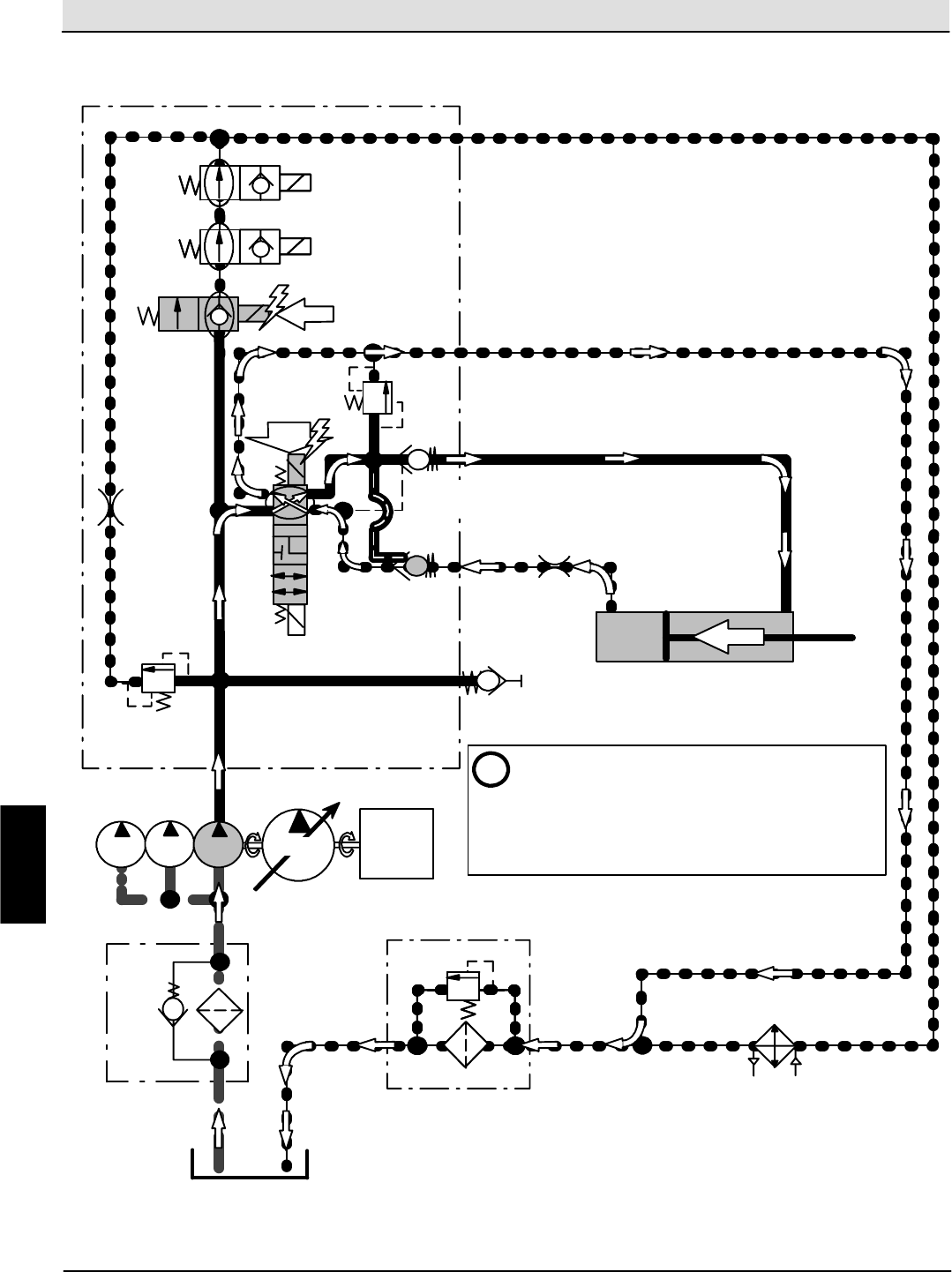
Hydraulic Troubleshooting S30 SERVICE INFORMATION
S30 9004086 (4--08)
116
Hopper Lower (S30, S30XP, S30X4)
Conditions: Engine Running, Hopper Lift Switch in LOWER Position
ENGINE
PUMP
4
PUMP
3
PUMP
2PUMP
1
RES1
20.7 kPa
RV8
(3 psi)
STRN1
P1
G1
SV4
TEST
PORT
OR1
172 BAR
RV1
(2500 psi)
(0.14 in)
3.5 mm
T2
SV1
HTX
172 kPa
RV9
(25 psi)
FLTR
SV3
C4
T1
3.5 mm
OR1
SV1
HTX
172 kPa
RV9
(25 psi)
FLTR
SV3
HOPPER LIFT CYLINDER
C5
OR
(0.47 in)
11.9 mm
LOWER
CYL2
SV6B
55 BAR
RV3
(800 psi)
PC2
6.9 BAR
(100 psi)
(100 psi)
6.9 BAR
PC3
SV6A
i-- When Hopper Lift Cylinder reaches the end of travel
when Lowering Hopper, Relief Valve (RV3) will open to
prevent excessive pressure build--up.
-- The Enable Valve (SV4) is turned ON whenever the
Hopper Lift Switch(SW22) is in the RAISE or LOWER
position.
MANIFOLD ASSEMBLY
H
Home
Find...
Go To..
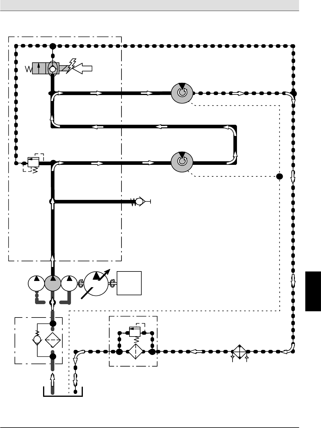
S30 SERVICE INFORMATION Hydraulic Troubleshooting
S30 9004086 (4--08) 117
Vacuum Fan ON (S30, S30XP, S30X4)
Conditions: Engine Running, Sweep System Activated, Vacuum System ON
ENGINE
PUMP
4
PUMP
3
PUMP
2PUMP
1
RES1
20.7 kPa
RV8
(3 psi)
STRN1
P2
G2 TEST
PORT
M5
172 BAR
RV2
(2500 psi)
ENGINE
COOLING FAN
MOTOR
M3
T2
HTX
172 kPa
RV9
(25 psi)
FLTR
SV2
VACUUM
FAN MOTOR
M6
MTR6
MTR5
MANIFOLD ASSEMBLY
H
Home
Find...
Go To..
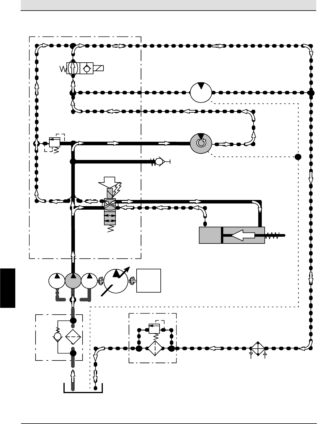
Hydraulic Troubleshooting S30 SERVICE INFORMATION
S30 9004086 (4--08)
118
Main Brush Lower (S30XP, S30X4)
Conditions: Engine Running, Sweep System Activated, Vacuum Fan OFF
RES1
20.7 kPa
RV8
(3 psi)
STRN1
P2
G2 TEST
PORT
M5
172 BAR
RV2
(2500 psi)
ENGINE
COOLING FAN
MOTOR
M3
T2
HTX
172 kPa
RV9
(25 psi)
FLTR
SV2
VACUUM
FAN MOTOR
M6
MTR6
MTR5
MAIN BRUSH
LIFT CYLINDER
LOWER
CYL4
ENGINE
PUMP
4
PUMP
3
PUMP
2PUMP
1
C8
C9
SV8
MANIFOLD ASSEMBLY
H
Home
Find...
Go To..
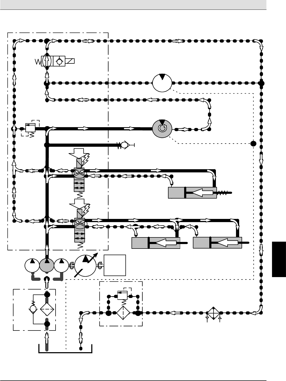
S30 SERVICE INFORMATION Hydraulic Troubleshooting
S30 9004086 (4--08) 119
Main Brush & Side Brush(es) Lower (S30XP, S30X4)
Conditions: Engine Running, Sweep System Activated, Side Brush(es) Activated, Vacuum Fan OFF
RES1
20.7 kPa
RV8
(3 psi)
STRN1
P2
G2 TEST
PORT
M5
172 BAR
RV2
(2500 psi)
ENGINE COOLING
FAN MOTOR
M3
T2
HTX
172 kPa
RV9
(25 psi)
FLTR
SV2
VACUUM
FAN MOTOR
M6
MTR6
MTR5
MAIN BRUSH LIFT CYLINDER
LOWER
CYL4
ENGINE
PUMP
4
PUMP
3
PUMP
2PUMP
1
C8
C9
SV8
RH SIDE BRUSH
LIFT CYLINDER
LOWER
CYL3
C6
C7
SV7
LH SIDE BRUSH
LIFT CYLINDER
LOWER
CYL6
MANIFOLD ASSEMBLY
H
Home
Find...
Go To..
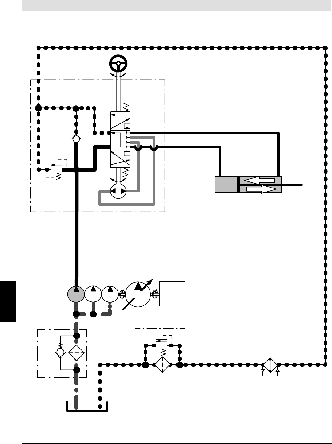
Hydraulic Troubleshooting S30 SERVICE INFORMATION
S30 9004086 (4--08)
120
3--Wheel Steering System (S30, S30XP)
ENGINE
PUMP
4
PUMP
3
PUMP
2PUMP
1
RES1
20.7 kPa
RV8
(3 psi)
STRN1
P
80 BAR
RV4
(1160 psi)
R
T
HTX
172 kPa
RV9
(25 psi)
FLTR
STEERING CYLINDER
RIGHT TURNCYL5
LEFT TURN
L
STEERING
WHEEL
STEERING VALVE ASSEMBLY
CK2
H
Home
Find...
Go To..
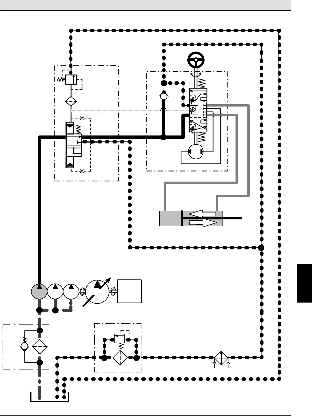
S30 SERVICE INFORMATION Hydraulic Troubleshooting
S30 9004086 (4--08) 121
4--Wheel Steering System (S30X4)
ENGINE
PUMP
4
PUMP
3
PUMP
2PUMP
1
RES1
20.7 kPa
RV8
(3 psi)
STRN1
P
82.7 BAR
RV4
(1200 psi)
CF
T
HTX
172 kPa
RV9
(25 psi)
FLTR
STEERING
WHEEL
LS
STEERING CYLINDER
RIGHT TURN
CYL5
LEFT TURN
CK2
E
P
R
L
EF
T
OR
(0.030 in)
0.76 mm
OR (0.026 in)
0.66 mm
OR
(0.026 in)
0.66 mm
STEERING
PRIORITY
VALVE
STEERING VALVE ASSEMBLY
H
Home
Find...
Go To..
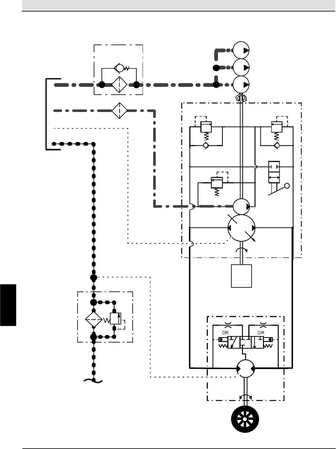
Hydraulic Troubleshooting S30 SERVICE INFORMATION
S30 9004086 (4--08)
122
3--Wheel Propel System (S30, S30XP)
RES1
20.7 kPa
RV8
(3 psi)
STRN1
PUMP
1ENGINE
PUMP
4
PUMP
3
PUMP
2
DRIVE
WHEEL
172 kPa
RV9
(25 psi)
FLTR
RV6
RV7
RV5
CK4
CK3
(4500 psi)
(3000 psi)
310 BAR
206 BAR
8.2 BAR
(120 psi)
MTR6
A
B
PUMP
1
PUMP
1A
CV
H
Home
Find...
Go To..
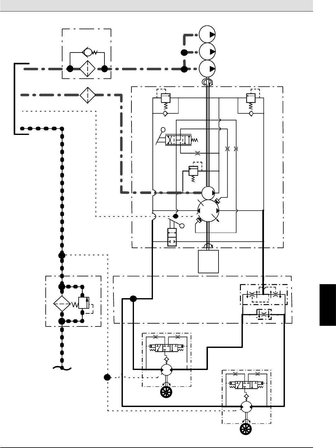
S30 SERVICE INFORMATION Hydraulic Troubleshooting
S30 9004086 (4--08) 123
4--Wheel Propel System (S30X4)
RES1
20.7 kPa
RV8
(3 psi)
STRN1
LEFT
DRIVE
WHEEL
172 kPa
RV9
(25 psi)
FLTR
MTR
6
PUMP
4
PUMP
3
PUMP
2
ENGINE
A
B
PROPEL
SYSTEM
FLOW
DIVIDER
VALVE
P1
M1
M2
P2
M4
M3
RIGHT
DRIVE
WHEEL
RV6
(4500 psi)
310 BAR
RV7
(3000 psi)
206 BAR
CK4
CK3
RV5
18.9 BAR
(275 psi)
PUMP
1
PUMP
1
CV1 CV2
CV3
CV4
MTR
7
RV
11 BAR
(160 psi)
RV
11 BAR
(160 psi)
PUMP
1A
H
Home
Find...
Go To..
Home
Find...
Go To..

We Need Your Help...
As part of Tennant’s Zero Defects Program, we want to know about errors you have
found or suggestions you may have regarding our machine manuals. If you find an
error or have a suggestion, please complete this postage-paid form and mail it to us.
Thank you for helping us make zero defects a way of life at Tennant.
Manual No. Rev. No. Publish Date Page
Machine -Report Error -Suggestion
Name Date
Customer Number
Company
Address
City/State/Zip Code
Home
Find...
Go To..

Tape hereFold along dotted lines
NO POSTAGE
NECESSARY
IF MAILED
IN THE
UNITED SATES
BUSINESS REPLY MAIL
FIRST CLASS MAIL PERMIT NO. 94 MINNEAPOLIS, MN
POSTAGE WILL BE PAID BY ADDRESSEE
Technical Publications #15
701 North Lilac Drive
P.O. Box 1452
Minneapolis, MN 55440--9947
TENNANT COMPANY
Home
Find...
Go To..

We Need Your Help...
As part of Tennant’s Zero Defects Program, we want to know about errors you have
found or suggestions you may have regarding our machine manuals. If you find an
error or have a suggestion, please complete this postage-paid form and mail it to us.
Thank you for helping us make zero defects a way of life at Tennant.
Manual No. Rev. No. Publish Date Page
Machine -Report Error -Suggestion
Name Date
Customer Number
Company
Address
City/State/Zip Code
Home
Find...
Go To..
Tape hereFold along dotted lines
NO POSTAGE
NECESSARY
IF MAILED
IN THE
UNITED SATES
BUSINESS REPLY MAIL
FIRST CLASS MAIL PERMIT NO. 94 MINNEAPOLIS, MN
POSTAGE WILL BE PAID BY ADDRESSEE
Technical Publications #15
701 North Lilac Drive
P.O. Box 1452
Minneapolis, MN 55440--9947
TENNANT COMPANY
Home
Find...
Go To..
