T16 Service Manual Tennant Rider Floor Scrubber
2018-06-20
: Sweepscrub Tennant-T16-Rider-Floor-Scrubber-Service-Manual tennant-t16-rider-floor-scrubber-service-manual 2788 file product_file
Open the PDF directly: View PDF ![]() .
.
Page Count: 200 [warning: Documents this large are best viewed by clicking the View PDF Link!]
- Start
- Table of Contents
- Safety Precautions
- General Information
- Maintenance
- Maintenance Chart
- Lubrication
- Batteries
- Circuit Breakers
- Electric Motors
- Scrub Brushes
- Side Brush
- Pre-Sweep Brushes
- FaST
- ec-H2O Module Flush Procedure
- Squeegee Blades
- Skirts and Seals
- Belts and Chains
- Tires
- Pushing, Towing, and Transporting the Machine
- Machine Jacking
- Storage Information
- Freeze Protection (without ec-H2O)
- Freeze Protection (with ec-H2O)
- Priming the ec-H2O System
- Troubleshooting
- Onboard Diagnostics
- Subsystem Troubleshooting
- Back-Up Alarm/Light
- Battery Charging
- Parking Brake, Electromagnetic
- Detergent Metering
- Extended Scrub
- Lighting
- Main Scrub Brushes
- Power-Up
- Pre-Sweep Brushes
- Pre-Sweep Lift
- Propel
- Rear Squeegee Lift
- Scrub Head Lift
- Side Brush
- Side Brush Lift
- Solution Control, Conventional
- Solution Control, ec-H2O
- Solution Control, FaST
- Spray Nozzle
- Vacuum Fan(s), Scrubbing
- Vacuum Fan, Pre-Sweep
- Service
- Service Procedures
- Component Testing
- Solution Tank Level Sensor
- Recovery Tank Level Sensor
- Parking Brake, Electromagnetic
- Propel Motor (and Encoder)
- Propel Motor Cables
- Throttle/Brake Sensor
- Pre-Sweep Lift Actuator
- Side Brush Lift Actuator
- Main Brush Lift Actuator
- Rear Squeegee Lift Actuator
- Vacuum Fan(s) (Scrubbing)
- Vacuum Fan (Pre-Sweep)
- Main Scrub Brush Motor(s)
- Main Sweep Broom Motor
- Side Brush Motor (Non Pre-Sweep)
- Side Brush Motor (Pre-Sweep)
- ec-H2O Pump
- ec-H2O Pressure Switch
- FaST Pump
- ES (Extended Scrub) Pump
- Table of Contents

T16
*9008149*
www.tennantco.com
Rider Scrubber
Service Information Manual
9008149
Rev. 00 (1-2011)
North America / International
The Safe Scrubbing Alternative R
Hygenic Fully Cleanable Tanks
ES Extended Scrub System
R
R
This manual provides necessary maintenance, troubleshooting and repair instructions.
Read this manual completely and understand the machine before operating or servicing it.
This machine will provide excellent service. However, the best results will be obtained at minimum costs if:
SThe machine is operated with reasonable care.
SThe machine is maintained regularly - per the machine maintenance instructions provided.
SThe machine is maintained with manufacturer supplied or equivalent parts.
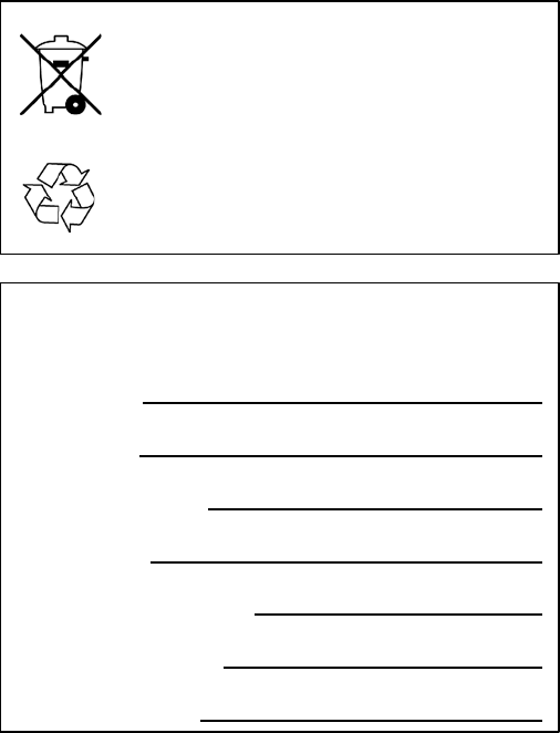
PROTECT THE ENVIRONMENT
Please dispose of packaging materials,
old machine components such as
batteries, hazardous fluids including
antifreeze and oil, in an
environmentally safe way according to
local waste disposal regulations.
Always remember to recycle.
MACHINE DATA
Please fill out at time of installation for future reference.
Model No. --
Serial No. --
Machine Options --
Sales Rep. --
Sales Rep. phone no. --
Customer Number --
Installation Date --
Tennant Company
PO Box 1452
Minneapolis, MN 55440
Phone: (800) 553--8033 or (763) 513--2850
www.tennantco.com
Touch--N--Go, 1--STEP, Grip--N--Go, Dura--Track, Positive Drain Control, SmartRelease, Duramer, FaST--PAK, are US registered and unregisteredtrade-
marks of Tennant Company.
Specifications and parts are subject to change without notice.
Original Instructions, copyright E2010 TENNANT Company, Printed in U.S.A.

T16 Service Information (1-11) 3
CONTENTS
Safety Precautions ...........................1-1
General Information . . . . . . . . . . . . . . . . . . . . . . . . . .2-1
Component Locator . . . . . . . . . . . . . . . . . . . . . . . . 2-2
Electrical Schematic, Master . . . . . . . . . . . . . . . . 2-4
Electrical Schematic Symbols . . . . . . . . . . . 2-10
Operational Matrix . . . . . . . . . . . . . . . . . . . . . . . . 2-11
Specications .............................2-14
Fastener Torque . . . . . . . . . . . . . . . . . . . . . . . . 2-14
General Machine Dimensions/
Capacities ...........................2-15
General Machine Performance . . . . . . . . . . 2-15
Power Type ............................2-16
Tires ...................................2-16
FaST System (Option) . . . . . . . . . . . . . . . . . . . 2-17
ec-H2O System (Option) . . . . . . . . . . . . . . . . 2-17
Electrical Components . . . . . . . . . . . . . . . . . 2-17
Machine Dimensions . . . . . . . . . . . . . . . . . . . 2-19
Maintenance .................................3-1
Maintenance Chart ......................... 3-2
Lubrication ................................ 3-4
Steering Chain .......................... 3-4
Rear Squeegee Casters . . . . . . . . . . . . . . . . . . 3-4
Steering Gear Chain . . . . . . . . . . . . . . . . . . . . . 3-4
Batteries ................................... 3-5
Charging the Batteries
(O-Board Charger) . . . . . . . . . . . . . . . . . . 3-6
Charging the Batteries
(Onboard Charger) . . . . . . . . . . . . . . . . . . . 3-7
Circuit Breakers ............................ 3-8
Electric Motors ............................. 3-8
Scrub Brushes ..............................3-9
Disk Brushes and Pads . . . . . . . . . . . . . . . . . . . 3-9
Replacing Disk Brushes
(or Pad Drivers) . . . . . . . . . . . . . . . . . . . . . . . 3-9
Replacing Disk Scrub Pads . . . . . . . . . . . 3-10
Cylindrical Brushes . . . . . . . . . . . . . . . . . . . . . 3-11
Replacing Cylindrical Brushes . . . . . . . . 3-11
Checking Cylindrical Scrub
Brush Pattern . . . . . . . . . . . . . . . . . . . . . 3-12
Adjusting Cylindrical Brush Taper . . . . 3-15
Adjusting Cylindrical Brush
Pattern Width . . . . . . . . . . . . . . . . . . . . . 3-16
Side Brush (Option) . . . . . . . . . . . . . . . . . . . . . . . 3-17
Replacing the Side Brush . . . . . . . . . . . . . . . 3-17
Pre-Sweep Brushes . . . . . . . . . . . . . . . . . . . . . . . . 3-18
Replacing the Pre-Sweep Disk Brushes . . 3-18
Replacing the Pre-Sweep
Cylindrical Brush . . . . . . . . . . . . . . . . . . . . 3-19
Checking and Adjusting Pre-Sweep
Cylindrical Brush Pattern . . . . . . . . . . . . 3-20
Contents Page
FaST ..................................3-24
Replacing the FaST-Pak Carton. . . . . . . . . . 3-24
Cleaning the FaST Supply Hose
Connector ..........................3-24
Replacing the FaST Injector Filters . . . . . . 3-24
ec-H2O Module Flush Procedure . . . . . . . . . . . 3-25
Squeegee Blades ..........................3-27
Replacing (or Rotating) the Rear
Squeegee Blades . . . . . . . . . . . . . . . . . . . . 3-27
Leveling the Rear Squeegee . . . . . . . . . . . 3-30
Adjusting the Rear Squeegee
Blade Deection . . . . . . . . . . . . . . . . . . . . 3-31
Replacing (or Rotating) the Side
Squeegee Blades . . . . . . . . . . . . . . . . . . . . 3-32
Replacing (or Rotating) the Side
Brush Squeegee Blade(s) (Option) . . . 3-33
Skirts and Seals ...........................3-35
Pre-Sweep Side Skirts (Option) . . . . . . . . . 3-35
Pre-Sweep Recirculation Skirt (Option) . . 3-35
Pre-Sweep Rear Skirt (Option) . . . . . . . . . . 3-35
Belts and Chains ..........................3-36
Steering Chain .........................3-36
Cylindrical Brush Drive Belts . . . . . . . . . . . . 3-36
Pre-Sweep Brush Drive Belt . . . . . . . . . . . . . 3-36
Tires ..................................3-36
Pushing, Towing, and Transporting
the Machine ...........................3-37
Pushing or Towing the Machine . . . . . . . . 3-37
Transporting the Machine . . . . . . . . . . . . . . 3-37
Machine Jacking ..........................3-39
Storage Information . . . . . . . . . . . . . . . . . . . . . . . 3-39
Freeze Protection (Machines without
Optional ec-H2O System) . . . . . . . . . . . . . . . 3-40
Preparing the Machine for Operation
(Machines without Optional
ec-H2O System) ........................3-41
Freeze Protection (Machines with
Optional ec-H2O System) . . . . . . . . . . . . . . . 3-42
Priming the ec-H2O System . . . . . . . . . . . . . . . 3-44
Troubleshooting .............................4-1
Onboard Diagnostics . . . . . . . . . . . . . . . . . . . . . . . 4-2
Self-Test Mode .......................... 4-2
Conguration Mode . . . . . . . . . . . . . . . . . . . . . 4-4
LCD Warnings ........................... 4-6
LCD Faults .............................. 4-7
Propel Diagnostic Mode . . . . . . . . . . . . . . . . . 4-9
Curtis 1234 Controller Diagnostics . . . . . . 4-11
Diagnostic LED Operation . . . . . . . . . . . 4-11
Diagnostic Codes . . . . . . . . . . . . . . . . . . . 4-12
Input Display Mode . . . . . . . . . . . . . . . . . . . . 4-20
Manual Mode ..........................4-22
Contents Page

CONTENTS
4T16 Service Information (1-11)
Battery Charger, Standard . . . . . . . . . . . . . . 4-24
Operation ...........................4-24
Conguration .......................4-24
Faults ...............................4-24
Battery Charger, Onboard Option . . . . . . . 4-25
Operation ...........................4-25
Conguration, Lead-Acid/Gel . . . . . . . . 4-25
Faults ...............................4-25
Subsystem Troubleshooting . . . . . . . . . . . . . . . 4-26
Back-Up Alarm/Light . . . . . . . . . . . . . . . . . . . 4-26
Electrical Schematic . . . . . . . . . . . . . . . . . 4-26
Troubleshooting . . . . . . . . . . . . . . . . . . . . 4-27
Battery Charging . . . . . . . . . . . . . . . . . . . . . . . 4-28
Electrical Schematic, Onboard . . . . . . . 4-28
Troubleshooting . . . . . . . . . . . . . . . . . . . . 4-29
Electrical Schematic, O Board . . . . . . . 4-30
Troubleshooting . . . . . . . . . . . . . . . . . . . . 4-31
Parking Brake, Electromagnetic . . . . . . . . . 4-32
Electrical Schematic . . . . . . . . . . . . . . . . . 4-32
Troubleshooting . . . . . . . . . . . . . . . . . . . . 4-33
Detergent Metering . . . . . . . . . . . . . . . . . . . . 4-34
Electrical Schematic . . . . . . . . . . . . . . . . . 4-34
Troubleshooting . . . . . . . . . . . . . . . . . . . . 4-35
Extended Scrub ........................4-36
Electrical Schematic . . . . . . . . . . . . . . . . . 4-36
Troubleshooting . . . . . . . . . . . . . . . . . . . . 4-37
Lighting ...............................4-38
Electrical Schematic . . . . . . . . . . . . . . . . . 4-38
Troubleshooting . . . . . . . . . . . . . . . . . . . . 4-39
Main Scrub Brushes . . . . . . . . . . . . . . . . . . . . 4-40
Electrical Schematic . . . . . . . . . . . . . . . . . 4-40
Troubleshooting . . . . . . . . . . . . . . . . . . . . 4-41
Power-Up ..............................4-42
Electrical Schematic . . . . . . . . . . . . . . . . . 4-42
Troubleshooting . . . . . . . . . . . . . . . . . . . . 4-43
Pre-Sweep Brushes . . . . . . . . . . . . . . . . . . . . . 4-44
Electrical Schematic . . . . . . . . . . . . . . . . . 4-44
Troubleshooting . . . . . . . . . . . . . . . . . . . . 4-45
Pre-Sweep Lift .........................4-46
Electrical Schematic, Down . . . . . . . . . . 4-46
Troubleshooting . . . . . . . . . . . . . . . . . . . . 4-47
Electrical Schematic, Up . . . . . . . . . . . . . 4-48
Troubleshooting . . . . . . . . . . . . . . . . . . . . 4-49
Propel .................................4-50
Electrical Schematic . . . . . . . . . . . . . . . . . 4-50
Troubleshooting . . . . . . . . . . . . . . . . . . . . 4-51
Rear Squeegee Lift . . . . . . . . . . . . . . . . . . . . . 4-52
Electrical Schematic . . . . . . . . . . . . . . . . . 4-52
Troubleshooting . . . . . . . . . . . . . . . . . . . . 4-53
Contents Page
Subsystem Troubleshooting, continued
Scrub Head Lift . . . . . . . . . . . . . . . . . . . . . . . . 4-54
Electrical Schematic . . . . . . . . . . . . . . . . . 4-54
Troubleshooting . . . . . . . . . . . . . . . . . . . . 4-55
Side Brush .............................4-56
Electrical Schematic . . . . . . . . . . . . . . . . . 4-56
Troubleshooting . . . . . . . . . . . . . . . . . . . . 4-57
Side Brush Lift .........................4-58
Electrical Schematic, Down . . . . . . . . . . 4-58
Troubleshooting . . . . . . . . . . . . . . . . . . . . 4-59
Electrical Schematic, Up . . . . . . . . . . . . . 4-60
Troubleshooting . . . . . . . . . . . . . . . . . . . . 4-61
Solution Control, Conventional . . . . . . . . . 4-62
Electrical Schematic . . . . . . . . . . . . . . . . . 4-62
Troubleshooting . . . . . . . . . . . . . . . . . . . . 4-63
Solution Control, ecH2O . . . . . . . . . . . . . . . . 4-64
Electrical Schematic . . . . . . . . . . . . . . . . . 4-64
Troubleshooting . . . . . . . . . . . . . . . . . . . . 4-65
Solution Control, FaST . . . . . . . . . . . . . . . . . . 4-66
Electrical Schematic . . . . . . . . . . . . . . . . . 4-66
Troubleshooting . . . . . . . . . . . . . . . . . . . . 4-67
Spray Nozzle ...........................4-68
Electrical Schematic . . . . . . . . . . . . . . . . . 4-68
Troubleshooting . . . . . . . . . . . . . . . . . . . . 4-69
Vacuum Fan(s), Scrubbing . . . . . . . . . . . . . . 4-70
Electrical Schematic . . . . . . . . . . . . . . . . . 4-70
Troubleshooting . . . . . . . . . . . . . . . . . . . . 4-71
Vacuum Fan, Pre-Sweep . . . . . . . . . . . . . . . . 4-72
Electrical Schematic . . . . . . . . . . . . . . . . . 4-72
Troubleshooting . . . . . . . . . . . . . . . . . . . . 4-73
Service ..................................5-1
Service Procedures . . . . . . . . . . . . . . . . . . . . . . . . . 5-2
Rear Squeegee Lift Actuator . . . . . . . . . . . . . 5-2
Removal ............................. 5-2
Installation ........................... 5-3
Side Brush Lift Actuator . . . . . . . . . . . . . . . . . 5-6
Removal ............................. 5-6
Installation ........................... 5-7
Main Brush Lift Actuator . . . . . . . . . . . . . . . . . 5-8
Removal ............................. 5-8
Installation ........................... 5-8
Main Scrub Head . . . . . . . . . . . . . . . . . . . . . . . . 5-9
Removal ............................. 5-9
Installation ..........................5-10
Main Scrub Brush Motor (Cylindrical) . . . 5-11
Removal ............................5-11
Installation ..........................5-12
Carbon Brushes . . . . . . . . . . . . . . . . . . . . . 5-12
Contents Page

T16 Service Information (1-11) 5
CONTENTS
Service Procedures, continued
Side Brush Motor (Non Pre-Sweep) . . . . . 5-13
Removal ............................5-13
Installation ..........................5-14
Carbon Brushes . . . . . . . . . . . . . . . . . . . . . 5-14
Instrument Panel . . . . . . . . . . . . . . . . . . . . . . . 5-15
Removal ............................5-15
Installation ..........................5-15
Logic Board ............................5-16
Removal ............................5-16
Installation ..........................5-17
Steering Cable Adjustment . . . . . . . . . . . . . 5-18
Steering Wheel Timing . . . . . . . . . . . . . . . . . 5-19
Wheel Drive Assembly . . . . . . . . . . . . . . . . . 5-20
Removal ............................5-20
Installation ..........................5-20
Tire Replacement . . . . . . . . . . . . . . . . . . . 5-20
Vacuum Fan Assembly (Scrubbing) . . . . . 5-22
Removal ............................5-22
Installation ..........................5-23
Component Testing . . . . . . . . . . . . . . . . . . . . . . . 5-24
Solution Tank Level Sensor . . . . . . . . . . . . . 5-24
Recovery Tank Level Sensor. . . . . . . . . . . . . 5-26
Parking Brake, Electromagnetic . . . . . . . . . 5-28
Propel Motor (and Encoder) . . . . . . . . . . . . 5-31
Propel Motor Cables . . . . . . . . . . . . . . . . . . . 5-33
Throttle/Brake Sensor . . . . . . . . . . . . . . . . . . 5-35
Pre-Sweep Lift Actuator . . . . . . . . . . . . . . . . 5-37
Side Brush Lift Actuator . . . . . . . . . . . . . . . . 5-38
Main Brush Lift Actuator . . . . . . . . . . . . . . . . 5-39
Rear Squeegee Lift Actuator . . . . . . . . . . . . 5-40
Vacuum Fan(s) (Scrubbing) . . . . . . . . . . . . . 5-41
Vacuum Fan (Pre-Sweep) . . . . . . . . . . . . . . . 5-42
Main Scrub Brush Motor(s) . . . . . . . . . . . . . 5-43
Main Sweep Broom Motor . . . . . . . . . . . . . . 5-44
Side Brush Motor (Non Pre-Sweep) . . . . . 5-45
Side Brush Motor (Pre-Sweep) . . . . . . . . . . 5-46
ec-H2O Pump ..........................5-47
Adjusting ec-H2O Flow Rate . . . . . . . . . 5-47
ec-H2O Pressure Switch . . . . . . . . . . . . . . . . 5-48
FaST Pump .............................5-49
ES (Extended Scrub) Pump . . . . . . . . . . . . . 5-50
Contents Page

CONTENTS
6T16 Service Information (1-11)

T16 Service Information 9008149 (1-11) 1-1
SAFETY PRECAUTIONS
The following precautions are used throughout
this manual as indicated in their description:
WARNING: To warn of hazards or
unsafe practices that could result in
severe personal injury or death.
CAUTION: To warn of unsafe practices
that could result in minor or moderate
personal injury.
FOR SAFETY: To identify actions that must be
followed for safe operation of equipment.
This machine is designed solely for scrubbing dirt
and dust in a well lit indoor environment. Tennant
does not recommend using this machine in any
other environment.
The following information signals potentially
dangerous conditions to the operator or
equipment. Read this manual carefully. Know
when these conditions can exist. Locate all safety
devices on the machine. Then, take necessary
steps to train machine operators. Report machine
damage or faulty operation immediately. Do not
use the machine if it is not in proper operating
condition.
WARNING: Batteries emit hydrogen gas.
Explosion or re can result. Keep
sparks and open ame away. Keep
covers open when charging.
WARNING: Flammable materials can
cause an explosion or re. Do not use
ammable materials in tank(s).
WARNING: Flammable materials or
reactive metals can cause an explosion
or re. Do not pick up.
FOR SAFETY:
1. Do not operate machine:
-- Unless trained and authorized.
-- Unless operation manual is read and
understood.
-- With brake disabled.
-- I t is not in proper operating
condition.
-- In ammable or explosive areas.
-- In areas with possible falling objects
unless equipped with overhead guard.
2. Before starting machine:
-- Make sure all safety devices are in
place and operate properly.
-- Check brakes and steering for proper
operation.
-- Adjust seat and fasten seat belt (if so
equipped).
3. When using machine:
-- Do not pick up burning or smoking
debris, such as cigarettes, matches or
hot ashes
-- Go slowly on inclines and slippery
surfaces.
-- Use care when backing machine.
-- Do not carry passengers on machine.
-- Follow mixing and handling
instructions on chemical containers.
-- Report machine damage or faulty
operation immediately.
4. Before leaving or servicing machine:
-- Stop on level surface.
-- Turn omachine and remove key.
5. When servicing machine:
-- Avoid moving parts. Do not wear loose
clothing or jewelry when working on
machine.
-- Block machine tires before jacking
machine up.
-- Jack machine up at designated
locations only. Block machine up with
jack stands.
-- Use hoist or jack that will support the
weight of the machine.
-- Wear eye and ear protection when
using pressurized air or water.
-- Disconnect battery connections before
working on machine.
-- Wear protective gloves and eye
protection when handling vinegar.
-- Avoid contact with battery acid.
-- Use Tennant supplied or equivalent
replacement parts.
6. When loading/unloading machine
onto/o truck or trailer.
-- Turn o machine.
-- Use truck or trailer that will support
the weight of the machine.
-- Use winch. Do not push the machine
onto/o the truck or trailer unless the
load height is 380 mm (15 in) or less
from the ground.
-- Block machine tires.
SAFETY PRECAUTIONS
1-2 T16 Service Information 9008149 (1-11)
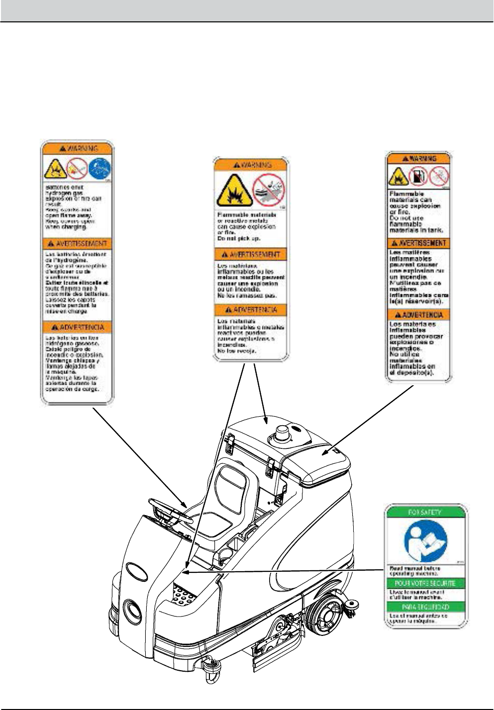
SAFETY PRECAUTIONS
The safety labels appear on the machine in the
locations indicated. Replace damaged labels.
BATTERY CHARGING
LABEL -- LOCATED
ON SEAT PANEL.
FLAMMABLE SPILLS
LABEL -- LOCATED ON
UNDERSIDE OF
SOLUTION TANK COVER.
FOR SAFETY LABEL --
LOCATED ON CIRCUIT
BREAKER PANEL.
FLAMMABLE MATERIALS
LABEL -- LOCATED ON
UNDERSIDE OF
RECOVERY TANK COVER
AND ON CIRCUIT
BREAKER PANEL.

General Information ........................... 2-1
Component Locator . . . . . . . . . . . . . . . . . . . . . . . . 2-2
Electrical Schematic, Master . . . . . . . . . . . . . . . . 2-4
Electrical Schematic Symbols . . . . . . . . . . . 2-10
Operational Matrix . . . . . . . . . . . . . . . . . . . . . . . . 2-11
Specications .............................2-14
Fastener Torque . . . . . . . . . . . . . . . . . . . . . . . . 2-14
General Machine Dimensions/
Capacities ...........................2-15
General Machine Performance . . . . . . . . . . 2-15
Power Type ............................2-16
Tires ...................................2-16
FaST System (Option) . . . . . . . . . . . . . . . . . . . 2-17
ec-H2O System (Option) . . . . . . . . . . . . . . . . 2-17
Electrical Components . . . . . . . . . . . . . . . . . 2-17
Machine Dimensions . . . . . . . . . . . . . . . . . . . 2-19
GENERAL INFORMATION
SECTION 2
Contents Page
2-1
T16 Service Information 9008149 (1-11)
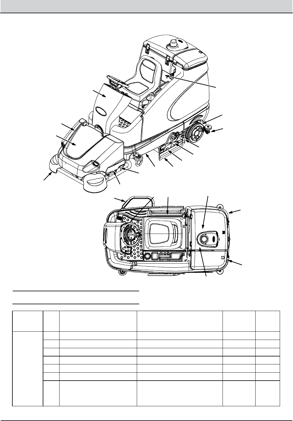
2-2 T16 Service Information 9008149 (1-11)
GENERAL INFORMATION
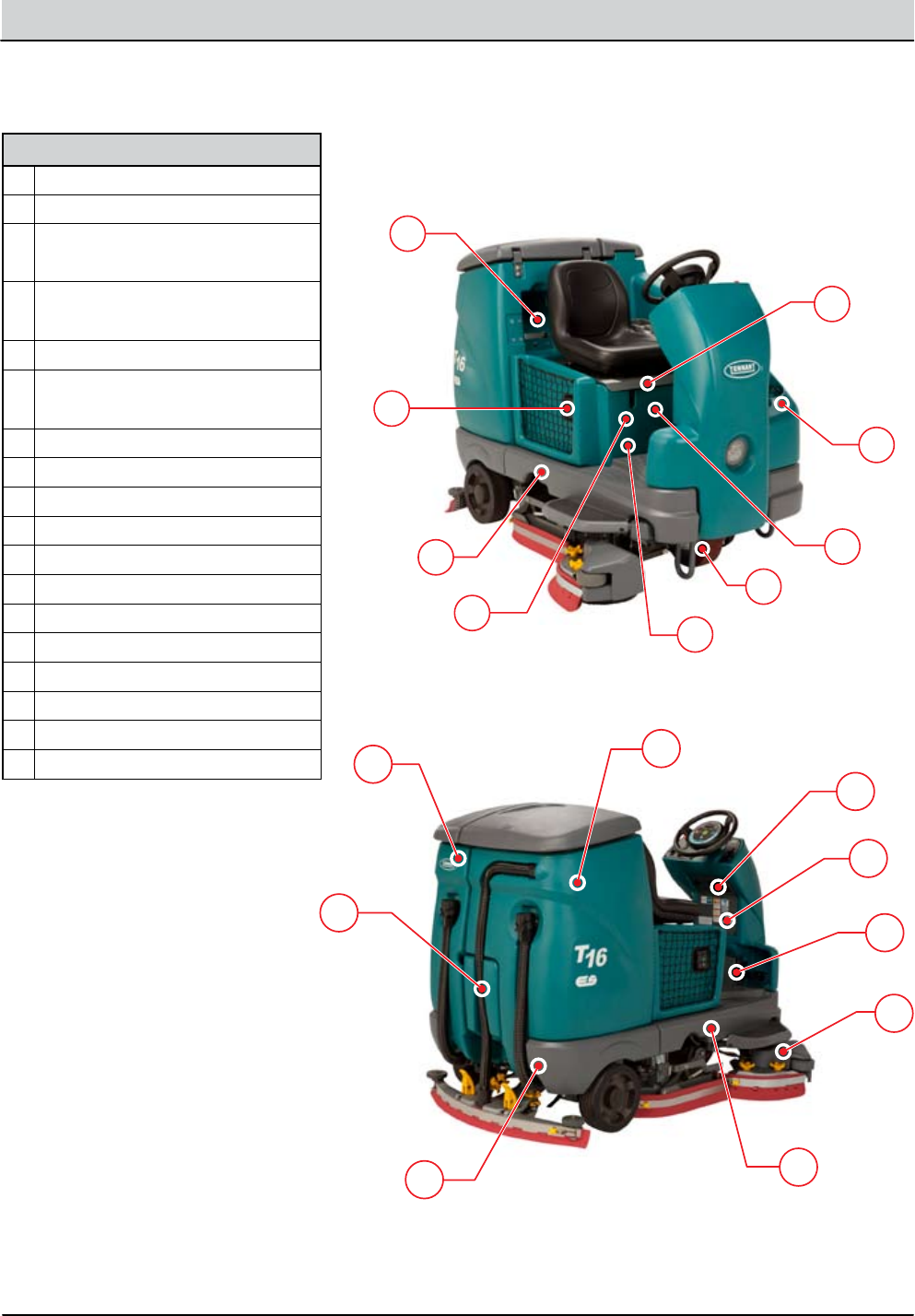
COMPONENT LOCATOR
A
B
C
D
E
F
G
H
I
J
K
LM
N
O
P
Q
R
Components
AFaST, ec-H2O System Components*
BOnboard Battery Charger*
CFaST, ec-H2O, Side Brush, ES, Spray
Nozzle Pumps*
DM1 and M2* Contactors,
Diodes (D-1, D-4, D-5*)
EFU-1 and FU-2 Fuses
FWheel Drive Assembly (Motor,
Encoder, Temp Sender
GLogic Board
HDetergent Metering Tank*
ICircuit Breakers (1-10)
JSolution Tank
KVacuum Fan Housing
LRear Squeegee Lift Actuator
MDetergent Metering Pump*
NSide Brush Motor*
OThrottle/Brake Sensor
PCurtis 1234 Controller
QCircuit Breakers (11-19)
RRecovery Tank
* Optional Equipment
T16 Service Information 9008149 (1-11) 2-3
GENERAL INFORMATION
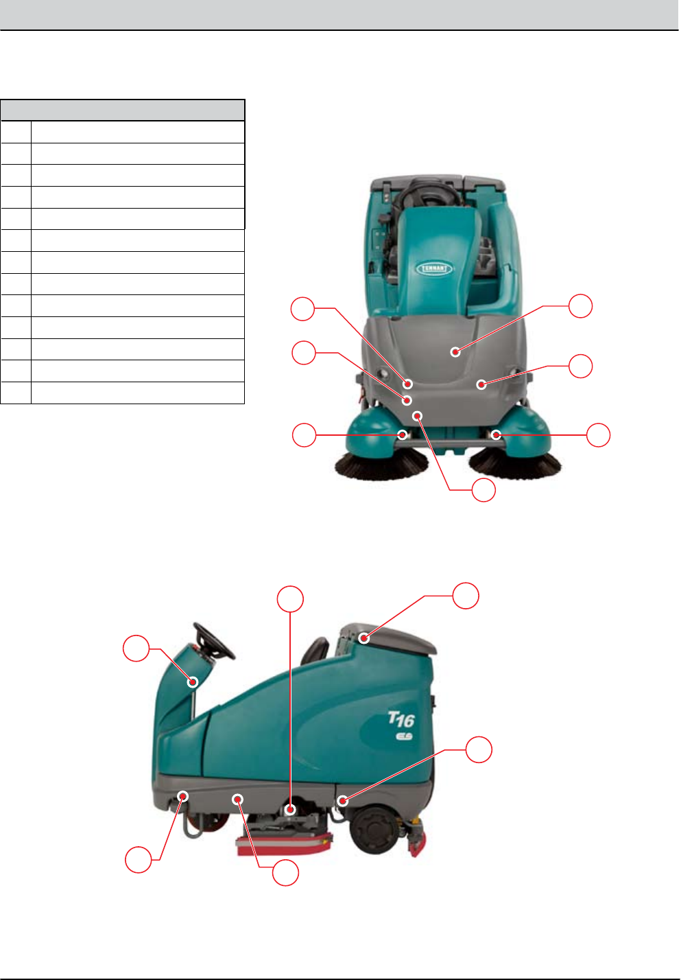
COMPONENT LOCATOR, continued
S
T
U
Y
X
W
V
Z
AA
BB
CC
DD
EE
Components
SDiodes (D-6 and D-9)*
TM3 and M4 Pre-Sweep Contactors*
URH Side Brush Motor*
VPre-Sweep Main Broom Motor*
WLH Side Brush Motor*
XPre-Sweep Vacuum Fan*
YPre-Sweep Lift Actuator*
ZDiodes (D-2, D-3, D-10*)
AA Side Brush Lift Actuator*
BB Main Brush Lift Actuator
CC Conventional Water Valve
DD Solution Tank Level Sensor
EE Main Brush Motors
* Optional Equipment
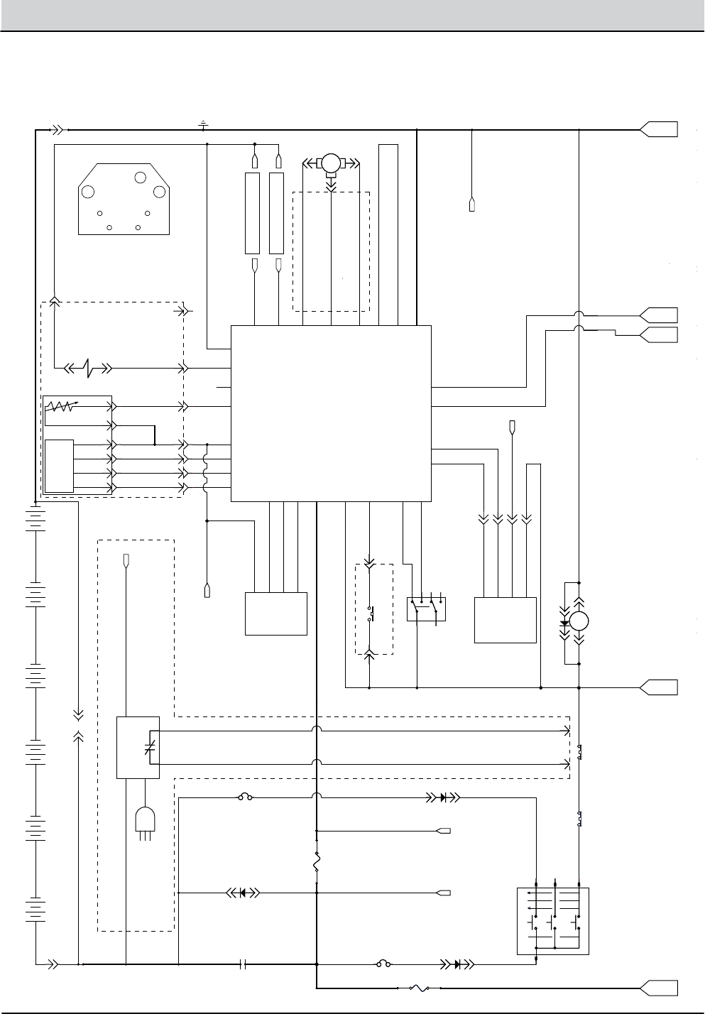
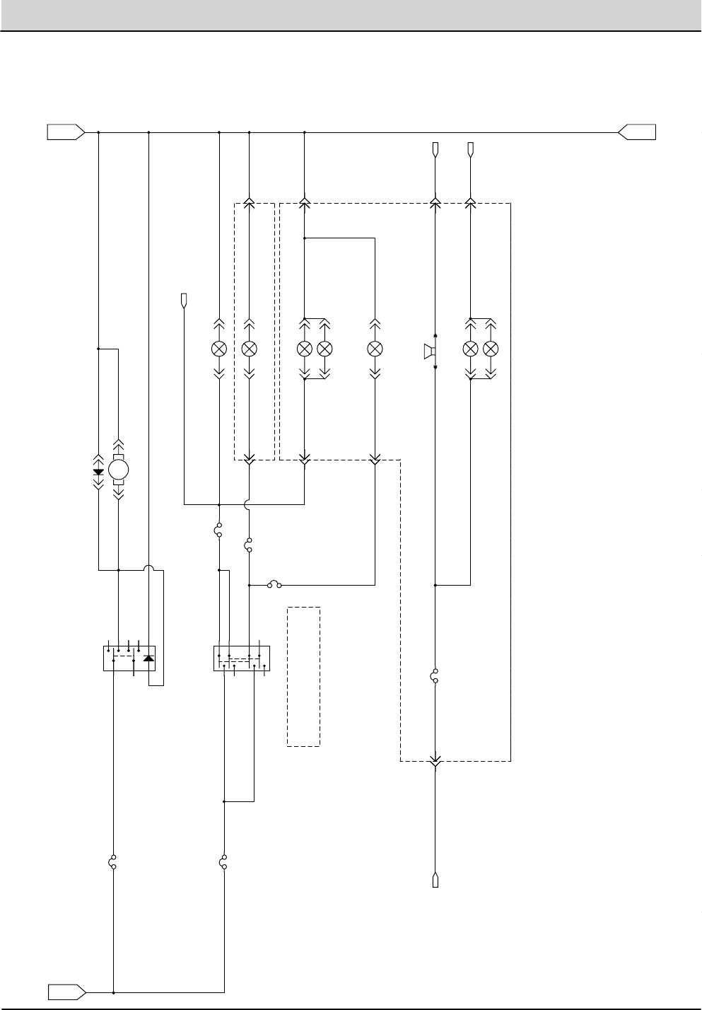
2-4 T16 Service Information 9008149 (1-11)
GENERAL INFORMATION
MTR1
1/RED
21/PNK
20/TAN
RED #1
19/WHT
RED #2
5/GRN
4/YEL
6/BLU
10/TAN
13/BLK
13/BLK
13/BLK13/BLK
8/GRY
RED
8/GRY
BLK
YEL
BLU
8/GRY
BLK #2
18/GRY
18/GRY
58/GRY
2/BRN
1/RED 3/ORA
16/BLU
14/YEL
8/GRY
GND POST - CURTIS 1234
CABLE FU-2 - CONTROL BD.
CABLE: BAT.- BAT. CONNECTOR
7/PUR
BUSS BAR
15/GRN
W/WHT
U/ORA
V/GRN
17/PUR
2/BRN
66/BLU
61/PNK
59/WHT
12/BRN
62/BRN
17/PUR
17/PUR
RED #2
BLK #1
BLK #2
RED #1
CABLE, BAT - GND POST GROUND = 13/BLK
58/GRY
YRG/8YRG/8
8/GRY
94/YEL
11/PNK
9/WHT
CABLE, FU-1 - CURTIS
84/YEL
83/ORA
82/BRN
58/GRY
58/GRY
2/BRN
102/BRN
SHIELD
BLK #1
RED
CABLE, BAT.- M1
BLK
87/PUR
13
17
15
58
58
2
102
2
17
87
36VDC BATTERIES
CAN BUS
AMER
ENCODER
CAN BUS
CABLE 8: BATTERY TO BATTERY (QTY 5)
TO: GROUND POSTTO: BATTERY B+ AT M1.
TO: OPTIONAL BACK UP
LIGHT
B1 B2SV1
PROPEL MOTOR
HARNESS
OPT. ON BOARD CHARGER
W
U
V
B2
T2T1
B1
A+
W1
A-
AC PROPEL MOTOR
PIN OUT
(FACING MOTOR)
AC PROPEL MOTOR
(INCLUDES ENCODER,
TEMP SENDER AND BRAKE SOL.)
GND POST
STAND OFF
SEAT SWITCH HARNESS
AC PLUG
SWITCHED B+
SWITCHED B+
NOT USED
STD: CHARGER CABLE
SWITCH OPENS IF
CHARGER PLUGGED IN.
TO GROUND.
13
TO: OPT. ON BOARD
BATTERY CHARGER
YEL
YEL
TO: OPTIONAL BACK UP
ALARM
5
D-4
4
B+
B+
J3-1
CAN_+12V
J2-1
CAN_+
J2-2
CAN_GND
J2-4
CAN_-
J2-3
B+_CONTROL
J7-1
CAN_OPEN+
J6-13
CAN_OPEN-
J6-14
J7-20
CONN11A
1
STIGN
BATT
START
ACC
X
XX
X
S1
75
15
50
30
S16
SENDER, TEMP
T2
T1
FU-2
100A
FU-2
100A
3
6 VDC
+ --
CONN7A
A
FU-1
100A
4
6 VDC
+ --
6
6 VDC
+ --
7
CONN11B
2
MAIN CONTACTOR
+
-
M1A
+
-
PROGRAMMING PORT
GND
2
B+
4
RX
1
TX
3
8
S-4A
ON
OFF
FWD/REV SW.
8
6
4
1
5
2
BLU
BLK
WHT
RED
2
THROTTLE SENSOR
BRAKE
P1-C
THROTTLE
P1-B
B+
P1-A
GND
P1-D
5
S-5
SEAT SWITCH
EM BRAKE
CB1
2.5A
S-3
MEMBRANE TOUCH PANEL
P1-1
P1-2
P1-3
P1-4
CB2
2.5A
CB2
2.5A
1
6
3
1
4 8
D-2D-2
6 VDC
+ --
CURTIS 1234 CONTROLLER
KSI
J1-1
DRV2
J1-5
DRV1
J1-6
INTERLOCK
J1-9
I/O GND
J1-7
36VDC
J1-13
BRAKE IN
J1-11
THROTTLE
J1-16
CAN TERM H
J1-21
FWD
J1-22
CAN H
J1-23
+5V
J1-26
PHASE A
J1-31
PHASE B
J1-32
REV
J1-33
CAN TERM L
J1-34
CAN L
J1-35
U
U
V
V
W
W
B+
B+
GND
GND
THERMISTOR
J1-8
DRV3
J1-4
DRV4
J1-3
PROG+
J1-25
TX
J1-28
RX
J1-29
2
3
12
CONN8B
B
2
6
7
1
4
6 VDC
+ --
3
M1B
MAIN
5
S-2
E-STOP SWITCH
CONN7B
B
6 VDC
+ --
2 1
D-3
CHG-1
OPT: ON BOARD CHARGER
P1-C
2
GND
P1-B
B+
P1-A
P1-D
1
D-1
5
6
AC PROPEL MOTOR
MTR9
CONN8A
A
CHARGER
INTERLOCK
A
B
C
D
E
ELECTRICAL SCHEMATIC (1 of 6)
T16 Service Information 9008149 (1-11) 2-5
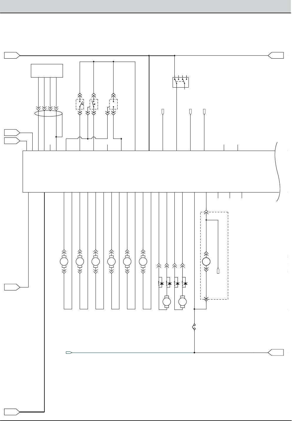
GENERAL INFORMATION
ELECTRICAL SCHEMATIC (2 of 6)
MTR3
MTR2
MTR5
MTR1
MTR6
MTR4
21/PNK
22/BRN
RED #1
RED #2
31/PNK
32/BRN
113/BLK-WHT50/TAN
51/PNK 113/BLK-WHT
6/BLU 13/BLK13/BLK13/BLK
8/GRY
8/GRY
BLK #2
49/WHT
27/PUR
29/WHT
28/GRY
30/TAN
40/TAN
2/BRN
2/BRN
23/ORA
24/YEL
25/GRN
26/BLU
34/YEL
36/BLU
42/BRN39/WHT
38/GRY
37/PUR37/PUR
38/GRY
41/PNK
39/WHT
39/WHT
THW/93THW/93
55/GRN 13/BLK
113/BLK-WHT113/BLK-WHT
65/GRN
56/BLU
57/PUR
CABLE FU-2 - CONTROL BD.
CABLE GND - CONTROL BD.
7/PUR
37/PUR
RED #2
BLK #1
BLK #2
RED #1
35/GRN
33/ORA
SHIELD
BLK #1
49/WHT
113/BLK-WHT53/ORA
38
54
56
57
2
CAN BUS
CAN BUS
SV2
TO: OPT. SWEEP VAC RELAY
DIGITAL GROUND
TO: PRESWEEP ENABLE
TO: EC-H2O RED DIAG.
TO: EC-H2O GRN DIAG.
OPT. PRESWEEP HARNESS
INSTR. PANEL HARNESS
SWITCH CLOSED
WHEN H20 SENSED
OUTPUT = GND/LOW
WHEN H20 SENSED
CLOSED / GROUND =
SIDE BRUSH
ENABLED.
+36V = PRESWEEP
ENABLED
SQGE UP/DN ACTUATOR
SIDE BRUSH UP/DN ACTUATOR
CYL=USE ADAPTOR #1059170 AT FRONT BRUSH MOTOR
2 @ B+ = EXTEND = LIFT
1 @ B+ = RETRACT = LOWER
D-4
QUANTUM CONTROL BOARD
B+
B+
GND
GND
BRUSH_RT-
J3-2
BRUSH_LT-
J3-6
BRUSH_RT+
J3-1
BRUSH_LT+
J3-5
VAC_1+
J4-1
VAC_1-
J4-2
VAC_2+
J4-3
VAC_2-
J4-4
SCB_ACT_2
J5-1
SCB_ACT_1
J5-2
SQGE_ACT_1
J5-6
SQGE_ACT_2
J5-5
SIDE_ACT_1
J5-4
SIDE_ACT_2
J5-3
SD.BRUSH+
J3-3
GND_DIGITAL
J6-11
OUTPUT_SPARE1
J7-15
SWEEP
J7-4
MAIN H2O
J7-5
HORN
J7-6
FLYBACK2
J7-8
REC FULL
J6-4
REC 1/2 FULL
J6-5
SOL LEVEL
J6-3
SIDE BRUSH
J6-6
SD.BRUSH-
J3-4
ECHO GRN
J6-8
CAN_+12V
J2-1
CAN_+
J2-2
CAN_GND
J2-4
CAN_-
J2-3
B+_CONTROL
J7-1
SWEEP EN.
J6-10
+5VDC
J6-2
CAN_OPEN+
J6-13
CAN_OPEN-
J6-14
+12VDC
J7-20
AUDIBLE ALARM
J7-7
FLYBACK1
J7-2
OUTPUT_SPARE3
J7-16
OUTPUT_SPARE2
J7-3
ECHO RED
J6-7
CAN GND1
J6-12
CAN GND2
J6-17
CONN11A
1
ACC
X
XX
75
15
LEFT/FRONT BRUSH MOTOR
2 1
CONN11B
2
MAIN CONTACTOR
+
-
M1A
+
-
S-3
MEMBRANE TOUCH PANEL
P1-1
P1-2
P1-3
P1-4
CB3
2.5A
CONN4E
5
SIDE BRUSH MOTOR
2 1
EXTEND LIMIT SW.
RETRACT LIMIT
BLACK
RED
BLACK
RED
MTR 8
1
2
N.O.S-6
REC. TANK FULL
A B
CB4
2.5A
CONN3ECONN3E
M4A
OPT. SWEEP BRUSH RELAY
8586
ALARM-1
AUDIBLE ALARM
P1-1 P2-1
VAC FAN #2
2 1
EXTEND LIMIT SW.
RETRACT LIMIT
BLACK
RED
BLACK
RED
MTR 7
1
2
S-2
E-STOP SWITCH
CONN4F
6
RIGHT/REAR BRUSH MOTOR
2 1
HORN-1
HORN
P1-1 P2-1
SCRUB UP/DOWN
2 1
GND
B+
OUT
S-8
SOL. TANK PRESS.SENSOR
B
C A
S-9A
ON
OFF
SIDE BRUSH SW.
8
6
4
1
5
2
VAC FAN #1
2 1
CONN3FCONN3F
C N.O.
B+
S-7
REC. TANK 1/2 FULL
A
B C
CHARGER
INTERLOCK
A
B
C
D
E
F
G
QUANTUM
CONTROL
BOARD
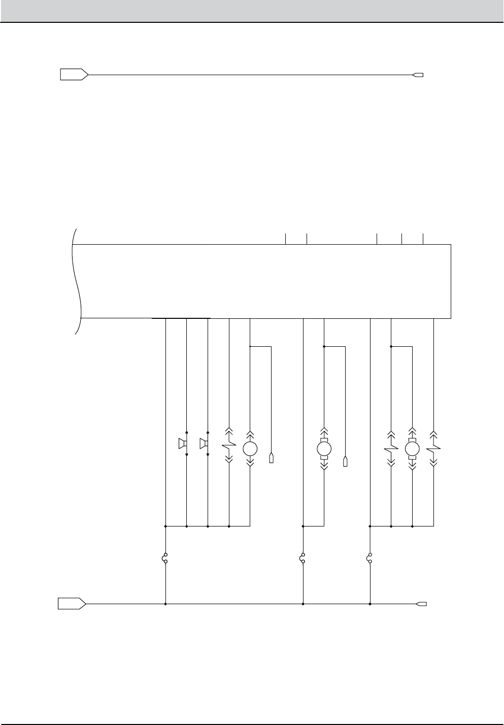
2-6 T16 Service Information 9008149 (1-11)
GENERAL INFORMATION
ELECTRICAL SCHEMATIC (3 of 6)
145/GRN
2/BRN
145/GRN
46/BLU
46/BLU
47/PUR
47/PUR
40/TAN
LEY/44LEY/44
44/YEL
ULB/64ULB/642/BRN
2/BRN
2/BRN
43/ORA
39/WHT 43/ORA
46/BLU 48/GRY
42/BRN39/WHT
38/GRY
37/PUR37/PUR
38/GRY
41/PNK
39/WHT
39/WHT
THW/93THW/93
13/BLK
56/BLU
57/PUR
37/PUR
35/GRN
45
2
13
43
38
56
57
OPT. ECH2O SIDE BRUSH
SWITCHED B+
GROUND
OPT. ECH2O ENABLE
SV4
SV3
SV2
TO: OPT. SWEEP VAC RELAY
TO: EC-H2O RED DIAG.
TO: EC-H2O GRN DIAG.
OPT. PRESWEEP HARNESS
QUANTUM CONTROL BOARD
SQGE_ACT_2
J5-5
CAN_J1939-
J6-16
CAN_J1939+
J6-15
INPUT_UNUSED1
J6-1
FAST/ECHO SIDEBRUSH
J7-9
OUTPUT_SPARE1
J7-15
SWEEP
J7-4
MAIN H2O
J7-5
HORN
J7-6
FLYBACK2
J7-8
SIDE SOLUTION
J7-14
ES/FAST/
ECHO RELAY
J7-10
ECHO GRN
J6-8
ECHO SIDE
FLOW/DET MET.
J7-12
AUDIBLE ALARM
J7-7
FLYBACK1
J7-2
FLYBACK3
J7-11
FLYBACK4
J7-13
OUTPUT_SPARE3
J7-16
OUTPUT_SPARE2
J7-3
ECHO RED
J6-7
INPUT_UNUSED2
J6-18
CAN GND1
J6-12
CAN GND2
J6-17
OPEN1
J6-9
MTR10
OPT. DET. METERING PUMP
A B
OPT. SIDE WATER METERING PUMP
MTR11
A B
CB3
2.5A
CONN4E
5
RETRACT LIMIT
BLACKBLACK
MTR19
2
CB4
2.5A
OPT. SIDE WATER VALVE
CONN3ECONN3E
M4A
OPT. SWEEP BRUSH RELAY
8586
M2A OPT. ES/FAST RELAY
8586
ALARM-1
AUDIBLE ALARM
P1-1 P2-1
CONN4F
6
CB5
2.5A
CB6
2.5A
OPT. FAST/ECHO SIDE BRUSH VALVE
MAIN SCRUB WATER VALVE
HORN-1
HORN
P1-1 P2-1
OFF
SIDE BRUSH SW.
4
1
2
CONN3FCONN3F
F
G
QUANTUM
CONTROL
BOARD
T16 Service Information 9008149 (1-11) 2-7
GENERAL INFORMATION
ELECTRICAL SCHEMATIC (4 of 6)
13/BLK
13/BLK13/BLK
13/BLK13/BLK
13
GROUND
GROUND
CONN13C
3
CONN14D
4
CONN13D
4
CONN14C
3
13/BLK
13/BLK67/PUR
67/PUR 13/BLK
13/BLK67/PUR
67/PUR
13/BLK
13/BLK81/PNK
81/PNK
D-6
OPT. PRESWEEP DUST VAC FAN
MTR14
MTR16
LEFT PRESWEEP BRUSH MOTOR
MTR15
RIGHT PRESWEEP BRUSH MOTOR
D-9
MTR17
MAIN PRESWEEP BRUSH MOTOR
72/BRN 72/BRN
64/YEL 64/YEL
CONN13B
2
CONN14A
1
CB19
25A
CONN13A
1
30 87
M3B
30 87
CONN14B
2
2/BRN 60/TAN
2/BRN
63/ORA
63/ORA
102/BRN
2
102
SWITCHED B+
SWITCHED B+
M2B
30 87
CB8
20A
CB7
15A
13/BLK
13/BLK
D-5
OPT. FAST/ES PUMP
MTR12
OPT. PRESWEEP HARNESS
65/GRN
65
TO: SWEEP ENABLE INPUT
(B+ = SWEEP ENABLED ON.)
SW-10
SWEEP OFF/DN. = 2-1, 6-5
SWEEP ON/CENTER = 2-3, 6-7
VAC & SWEEP ON/UP = 3-4, 7-8
CONN3H
CONN3A
1
CONN4A
1
65/GRN69/WHT
70/TAN
69/WHT
69/WHT
70/TAN
70/TAN 38/GRY
105/GRN 105/GRN
38
TO: SWEEP OUTPUT
(GND. = SWEEP ON.)
HOPPER STATIC GND
CONN4D
D-12
M3A
OPT. SWEEP VAC FAN RELAY
85 86
CONN3D
PRESWEEP BRUSH LIFT ACTUATOR
CHASSIS GND
D-7
D-11
102/BRN
68/GRY
68/GRY
13/BLK
13/BLK 71/PNK
71/PNK
65/GRN
69/WHT
76/BLU
76
TO: LIGHT SWITCH
CB16
15A
CONN4B
2
PRESWEEP SWITCH
12
4
3
56
78
CONN3G
7
CONN3C
3
CONN4G
7
CONN4C
3
CONN3B
2
13/BLK74/YEL
13/BLK
13/BLK
13/BLK
13/BLK
SPRAY NOZZLE SWITCH
D-10
13/BLK
8 8
CONN4H
65/GRN
71/PNK
76/BLU
76/BLU
OPT. PRESWEEP HARNESS
PRESWEEP RIGHT HEADLIGHT (LED)
LT7
MTR18
PRESWEEP LEFT HEADLIGHT (LED)
LT6
74/YEL
102/BRN 73/ORA 74/YEL
CB14
15A
1
24
5
MTR19
4 4
1
2
EXTEND LIMIT SW.
RETRACT LIMIT
BLACK
RED
BLACK
RED
H
I
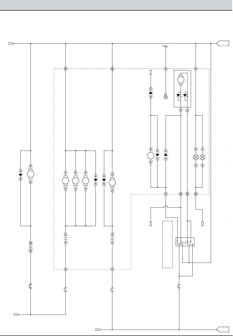
2-8 T16 Service Information 9008149 (1-11)
GENERAL INFORMATION
ELECTRICAL SCHEMATIC (5 of 6)
76/BLU
76
TO: LIGHT SWITCH
13/BLK74/YEL
13/BLK
13/BLK
13/BLK
SPRAY NOZZLE SWITCH
D-10
76/BLU
OPT. PRESWEEP HARNESS
PRESWEEP RIGHT HEADLIGHT (LED)
74/YEL
13/BLK13/BLK
102/BRN 73/ORA 74/YEL
CB14
15A
S-12
1
24
5
68
910
SPRAY NOZZLE PUMP
MTR19
75/GRN102/BRN 75/GRN
75/GRN
LIGHTS OFF/DN = 2-1, 6-5
HEADLIGHT ON/CENTER = 2-3, 6-7
HEAD & WARN ON/UP = 3-4, 7-8
CB11
15A
77/PUR
78/GRY
77/PUR
S-13
12
4
3
56
78
CB15
2.5A
CB12
2.5A
CB13
2.5A
LIGHT SWITCH
13/BLK
76/BLU
76/BLU
13/BLK
76/BLU
92/BRN
93/ORA 13/BLK
76
TO: OPT. SWEEP HARNESS
CONN9C
3 6
CONN10C
3
CONN16B
2
CONN15B
2
LT2
CENTER HEADLIGHT (LED)
LT1
CONN16A
1
CONN9F
6
RED TAILLIGHT (LED)
OHG FLASH/STROBE LIGHT
LT4
CONN15A
1
CONN10F
13/BLK92/BRN
CONN9D
4
CONN10D
4
FLASH/STROBE LIGHT
LT3
90/TAN
17/PUR
NAT/09NAT/09
17/PUR
17
+36VDC FROM CONTROLLER
CONN9A
1
CONN10A
1
CB20
2.5A
15/GRN
15/GRN
13/BLK
87/PUR 87/PUR
15
87
OPT. LIGHT / ALARM HARNESS
NOT USED
LOW = ALARM
LOW = BK. UP
LIGHT
CONN10E
5
CONN6G
7
CONN5G
ALARM-2
REVERSE ALARM
P1-1 P2-1
CONN9B
2
WHT, BACK UP LIGHT (LED)
CONN10B
2
LT5
CONN6H
8
CONN9E
5
CONN5H
8
43/ORA
43/ORA
145/GRN
145/GRN
43
145
EC-H2O ENABLE
LOW = TURN ON EC-H2O
EC-H2O SIDE BRUSH
LOW = SIDE BRUSH EC-H2O ON.
EC-H2O PUMP ON 100%.
CONN6C
3
CONN5F
6
CONN6F
6
CONN5C
3
2/BRN
2
SWITCHED B+
79/WHT
79/WHT
79/WHT
145/GRN
CONN5A
1
CB9
2.5A
CONN6A
1 10
11
(mode)
ENABLE
VCC_A
4
7
H
I
J
13/BLK

T16 Service Information 9008149 (1-11) 2-9
GENERAL INFORMATION
ELECTRICAL SCHEMATIC (6 of 6)
13/BLK
OPT. LIGHT / ALARM HARNESS
LIGHT
CONN9B
WHT, BACK UP LIGHT (LED)
CONN10B
CONN6H
8
CONN5H
88
43/ORA
43/ORA
145/GRN
145/GRN
43
145
EC-H2O ENABLE
LOW = TURN ON EC-H2O
EC-H2O SIDE BRUSH
LOW = SIDE BRUSH EC-H2O ON.
EC-H2O PUMP ON 100%.
CONN6C
3
CONN5F
6
CONN6F
6
CONN5C
3
2/BRN
2
SWITCHED B+
P1-1
2/BRN 45/GRN80/TAN
79/WHT
79/WHT
79/WHT
79/WHT
80/TAN 45/GRN
80/TAN 45/GRN
145/GRN
145/GRN
(A) (B)
(CAT.) (ANO.)
+ -
EC-H2O SOLUTION PUMP
R1
11 OHM/40W
P2-1
C1
CAPACITOR
CONN5A
1
CB10
2.5A
CB9
2.5A
CONN6A
1
8
10
11
12
CONN5B
2
CONN6B
8EA/GRY
7EA/PUR
3EA/ORA
4EA/YEL
6EA/BLU
5EA/GRN
(ECHO sparger)
(ECHO valve)
(ECHO cell)
ECH20 MODULE
1
2
3
6-1
6-2
6-3
6-6
6-5
6-7
MTR20
D-8
(mode)
ECHO MODULE
LED GND
LED GRN
LED RED
ENABLE
GND_A
GND_B
ALARM
PUMP
PRESS IN
VCC_A
VCC_B
VCC_C
(SOLA)
(SOLB)
(SPAA)
(SPAB)
(CELLA)
(CELLB)
(ECHO SW)
(ECHO SW)
13/BLK
13/BLK
13/BLK
88/GRY
13/BLK
13EA/BLK
9EA/WHT (ECHO flush sw)
S-15
4
5
6
7
9
6-4
6-8
COM NC
NO
SW-14
PRESS NC, OPENS @ 25PSI +/-2PSI
57/PUR57/PUR
56/BLU 56/BLU
57
56
SOLID GREEN = ECHO MODULE ON & SCRUBBING
SOLID RED = OVER CURRENT OF
FLASHING RED = PRESSURE SWITCH CLOSED "E-CELL IS SCALED UP"
TO CONTROL BOARD
EC-H2O INPUTS
CONN6D
4
CONN6E
5
CONN5E
5
CONN5D
4
OPT. EC-H2O HARNESS
SOLUTION PUMP OR SPARGER
J
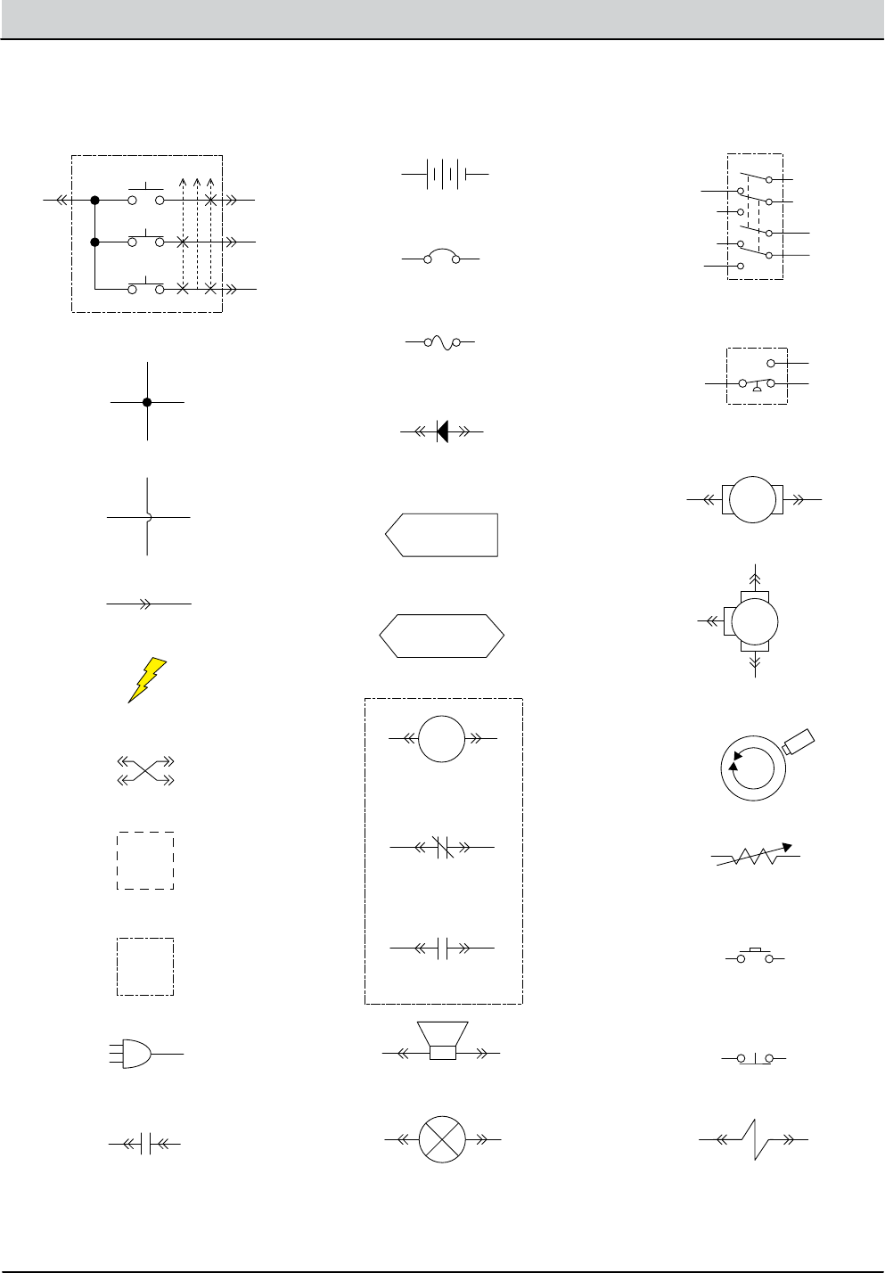
2-10 T16 Service Information 9008149 (1-11)
GENERAL INFORMATION
ELECTRICAL SCHEMATIC SYMBOLS
+ -
IGN ST
+-
Key Switch
Battery
DPDT Switch
Pressure Switch
Motor
3 Phase AC
Induction Motor
Motor Encoder
Momenary Switch N.O.
Contact Switch N.C.
Solenoid Valve
Sensor
(Variable Resistor)
Circuit Breaker
Fuse
Diode
Single Continuation Tab
Double Continuation Tab
Relay Coil
N.C. Relay Contacts
N.O. Relay Contacts
Horn or Alarm
Light
Connected
Not Connected
Connector
Energized
Adaptor Harness
Notes
Assembly
AC Plug
Capacitor

T16 Service Information 9008149 (1-11) 2-11
GENERAL INFORMATION
OPERATIONAL MATRIX
FUNCTION ENABLED
T16 OPERATIONAL MATRIX
DISABLED
Vacuum Fan(s), Scrubbing • 1-STEP Scrub ON
• Squeegee/Vacuum ON
• 1-STEP Scrub OFF
• Squeegee/Vacuum OFF
• Recovery Tank Full
• Very Low Battery Voltage
• Load Current Fault
Rear Squeegee Down • 1-STEP Scrub ON
• Squeegee/Vacuum ON
• 1-STEP Scrub OFF
• Squeegee/Vacuum OFF
• Reverse Propel
• Recovery Tank Full
• Very Low Battery Voltage
• Load Current Fault
Rear Squeegee Up • 1-STEP Scrub ON
• Squeegee/Vacuum ON
• 1-STEP Scrub OFF
• Squeegee/Vacuum OFF
• Reverse Propel
• Recovery Tank Full
• Very Low Battery Voltage
• Load Current Fault
Main Scrub Brushes • 1-STEP Scrub ON
• Fwd/Rev Throttle Command
• 1-STEP Scrub OFF
• Neutral - Ready State
• Recovery Tank Full
• Solution Tank Empty
• Very Low Battery Voltage
• Load Current Fault
Scrub Head Down • 1-STEP Scrub ON
• Fwd/Rev Throttle Command
• 1-STEP Scrub OFF
• Neutral - Ready State
• Recovery Tank Full
• Solution Tank Empty
• Very Low Battery Voltage
• Load Current Fault
Scrub Head Up • 1-STEP Scrub ON
• Fwd/Rev Throttle Command
• 1-STEP Scrub OFF
• Neutral - Ready State
• Recovery Tank Full
• Solution Tank Empty
• Very Low Battery Voltage
• Load Current Fault
Side Brush Extend/Down
(Non Pre-Sweep)
• 1-STEP Scrub ON
• Side Brush Switch ON
• 1-STEP Scrub OFF
• Side Brush Switch OFF
• Recovery Tank Full
• Solution Tank Empty
• Very Low Battery Voltage
• Load Current Fault
MOM001

2-12 T16 Service Information 9008149 (1-11)
GENERAL INFORMATION
OPERATIONAL MATRIX, continued
FUNCTION ENABLED
T16 OPERATIONAL MATRIX, continued
DISABLED
Solution Control
(FaST)
• 1-STEP Scrub ON
• Solution Control ON
• FaST Button ON
• Fwd/Rev Throttle Command
• 1-STEP Scrub OFF
• Solution Control OFF
• FaST Button OFF
• Neutral - Ready State
• Recovery Tank Full
• Solution Tank Empty
• Very Low Battery Voltage
• Load Current Fault
Solution Control
(ecH2O)
• 1-STEP Scrub ON
• Solution Control ON
• ecH2O Button ON
• Fwd/Rev Throttle Command
• 1-STEP Scrub OFF
• Solution Control OFF
• ecH2O Button OFF
• Neutral - Ready State
• Recovery Tank Full
• Solution Tank Empty
• Very Low Battery Voltage
• ecH2O System Fault
• Load Current Fault
Extended Scrub • 1-STEP Scrub ON
• Solution Control ON
• ES Button ON
• Recovery Tank 1/2 Full
• 1-STEP Scrub OFF
• Solution Control OFF
• ES Button OFF
• Recovery Tank Full
• Solution Tank Full
• Very Low Battery Voltage
• Load Current Fault
MOM002
Solution Control
(Conventional)
• 1-STEP Scrub ON
• Solution Control ON
• Fwd/Rev Throttle Command
• 1-STEP Scrub OFF
• Solution Control OFF
• Neutral - Ready State
• Recovery Tank Full
• Solution Tank Empty
• Very Low Battery Voltage
• Load Current Fault
Side Brush Retract/Up
(Non Pre-Sweep)
• 1-STEP Scrub ON
• Side Brush Switch ON
• 1-STEP Scrub OFF
• Side Brush Switch OFF
• Recovery Tank Full
• Solution Tank Empty
• Very Low Battery Voltage
• Load Current Fault
Side Brush
(Non Pre-Sweep)
• 1-STEP Scrub ON
• Side Brush Switch ON
• Fwd/Rev Throttle Command
• 1-STEP Scrub OFF
• Side Brush Switch OFF
• Neutral - Ready State
• Recovery Tank Full
• Solution Tank Empty
• Very Low Battery Voltage
• Load Current Fault

T16 Service Information 9008149 (1-11) 2-13
GENERAL INFORMATION
OPERATIONAL MATRIX, continued
Pre-Sweep Vacuum Fan • Pre-Sweep/Vacuum Fan Switch ON
• Fwd/Rev Throttle Command
• Pre-Sweep/Vacuum Fan Switch OFF
• Neutral - Ready State
• Very Low Battery Voltage
• Load Current Fault
FUNCTION ENABLED
T16 OPERATIONAL MATRIX, continued
DISABLED
Back-Up Alarm/Lights • Reverse Switch Input
• Reverse Throttle Command
• Forward Switch Input
• Neutral - Ready State
• Curtis 1234 Fault
Electromagnetic Parking
Brake
• Key OFF
• Emergency Stop Switch Open (Down)
• Neutral (1-2 Second Delay)
• Seat Switch Open
• Curtis 1234 Fault
• Key ON
• Emergency Stop Switch Closed (Up)
• Fwd/Rev Throttle Command
• Seat Switch Closed
MOM003
Propel • Seat Switch Closed
• Fwd/Rev Throttle Command
• Fwd/Rev Switch Input
• Seat Switch Open
• Neutral - Ready State
• Brake Command
• Curtis 1234 Fault
Detergent Metering • 1-STEP Scrub ON
• Solution Control ON
(Conventional Only)
• 2 or 3 Solution LEDs ON
• Fwd/Rev Throttle Command
• 1-STEP Scrub OFF
• Solution Control OFF
• 0 or 1 Solution LEDs ON
• Neutral - Ready State
• Recovery Tank Full
• Solution Tank Empty
• Very Low Battery Voltage
• Load Current Fault
Pre-Sweep Brushes • Pre-Sweep Switch ON
• Fwd/Rev Throttle Command
• Pre-Sweep Switch OFF
• Neutral - Ready State
• Very Low Battery Voltage
• Load Current Fault
Pre-Sweep Brushes Down • Pre-Sweep Switch ON • Pre-Sweep Switch OFF
Pre-Sweep Brushes UP • Pre-Sweep Switch OFF • Pre-Sweep Switch ON

2-14 T16 Service Information 9008149 (1-11)
GENERAL INFORMATION
FASTENER TORQUE
Thread
Size
SAE
Grade 1
SAE
Grade 2
Carriage
Bolts
Thread
Cutting
Thread
Rolling
SAE
Grade 5
Socket &
Stainless
Steel
SAE
Grade 8
Headless
Socket Set
Screws
Square
Head Set
Screws
4 (.112) (5) - (6.5) (4) - (6)
5 (.125) (6) - (8) (9) - (11)
6 (.138) (7) - (9) (20) - (24) (9) - (11)
8 (.164) (12) - (16) (40) - (47) (17) - (23)
10 (.190) (20) - (26) (50) - (60) (31) - (41)
1/4 (.250) 4 - 5 5 - 6 7 - 10 7 - 10 10 - 13 6 - 8 17 - 19
5/16 (.312) 7 - 9 9 - 12 15 - 20 15 - 20 20 - 26 13 - 15 32 - 38
3/8 (.375) 13 - 17 16 - 21 27 - 35 36 - 47 22 - 26 65 - 75
7/16 (.438) 20 - 26 26 - 34 43 - 56 53 - 76 33 - 39 106 - 124
1/2 (.500) 27 - 35 39 - 51 65 - 85 89 - 116 48 - 56 162 - 188
5/8 (.625) 80 - 104 130 - 170 171 - 265 228 - 383
3/4 (.750) 129 - 168 215 - 280 313 - 407 592 - 688
1 (1.000) 258 - 335 500 - 650 757 - 984 1281 - 1489
Thread
Size
4.8/5.6 8.8
Stainless Steel
10.9 12.9 Set
Screws
M3 43 - 56 Ncm 99 - 128 Ncm 139 - 180 Ncm 166 - 215 Ncm 61 - 79 Ncm
M4 99 - 128 Ncm 223 - 290 Ncm 316 - 410 Ncm 381 - 495 Ncm 219 - 285 Ncm
M5 193 - 250 Ncm 443 - 575 Ncm 624 - 810 Ncm 747 - 970 Ncm 427 - 554 Ncm
M6 3.3 - 4.3 Nm 7.6 - 9.9 Nm 10.8 - 14 Nm 12.7 - 16.5 Nm 7.5 - 9.8 Nm
M8 8.1 - 10.5 Nm 18.5 - 24 Nm 26.2 - 34 Nm 31 - 40 Nm 18.3 - 23.7 Nm
M10 16 - 21 Nm 37 - 48 Nm 52 - 67 Nm 63 - 81 Nm
M12 28 - 36 Nm 64 - 83 Nm 90 - 117 Nm 108 - 140 Nm
M14 45 - 58 Nm 102 - 132 Nm 142 - 185 Nm 169 - 220 Nm
M16 68 - 88 Nm 154 - 200 Nm 219 - 285 Nm 262 - 340 Nm
M20 132 - 171 Nm 300 - 390 Nm 424 - 550 Nm 508 - 660 Nm
M22 177 - 230 Nm 409 - 530 Nm 574 - 745 Nm 686 - 890 Nm
M24 227 - 295 Nm 520 - 675 Nm 732 - 950 Nm 879 - 1140 Nm
METRIC
SAE (STANDARD)

T16 Service Information 9008149 (1-11) 2-15
GENERAL INFORMATION
SPECIFICATIONS
Item Dimension/Capacity
Length 1880 mm (74 in)
Length (with Pre-Sweep) 2510 mm (99 in)
Width (less squeegee) 1040 mm (41 in)
Width (with squeegee frame) 1070 mm (42 in)
Width (with side brush) 1170 mm (46 in)
Height 1475 mm (58 in)
Height with overhead guard 2080 mm (82 in)
Disk brush diameter for side brush (option) 330 mm (13 in)
Disk brush diameter for Pre-Sweep (option) 460 mm (18 in)
Disk brush diameter 460 mm (18 in)
Cylindrical sweep brush diameter for Pre-Sweep (option) 200 mm (8 in)
Cylindrical sweep brush length for Pre-Sweep (option) 610 mm (24 in)
Cylindrical scrub brush diameter 205 mm (8 in)
Cylindrical brush length 910 mm (36 in)
Scrubbing path width 910 mm (36 in)
Cleaning path width (with scrubbing side brush) 1145 mm (45 in)
Cleaning path width (with sweeping side brush - cylindrical only) 1170 mm (46 in)
Cleaning path width (with dual side brushes - Pre-Sweep only) 1170 mm (46”
Solution tank capacity 190 L (50 gallons)
Solution tank capacity (with optional ES system) 280 L (75 gallons)
Recovery tank capacity 227 L (60 gallons)
Pre-Sweep hopper capacity 42 L (1.5 ft³)
Pre-Sweep dust bag capacity 28 L (1.0 ft³)
Weight (Empty) 500 Kg (1100 lbs)
Weight (with standard 235 AH batteries) 860 Kg (1900 lbs)
GVWR 1270 Kg (2800 lbs)
GENERAL MACHINE DIMENSIONS/CAPACITIES
Item Measure
Aisle turnaround width 2110 mm (83 in)
Aisle turnaround width (with Pre-Sweep) 2620 mm (103 in)
Travel Speed (Forward) 9.6 Km (5.6 mph)
Travel Speed (Reverse) 4 Km (2.5 mph)
Maximum rated climb and descent angle for transport 8˚ / 14%
Maximum rated climb and descent angle for scrubbing 4˚ / 7%
Maximum rated climb and descent angle for trailering 11˚ / 20%
Sound level at operator’s ear (economy mode) Disk 68 dBA, Cylindrical 71 dBa
GENERAL MACHINE PERFORMANCE

2-16 T16 Service Information 9008149 (1-11)
GENERAL INFORMATION
Item Measure
Runtime (economy mode) 235 AH, Up to 2 hours
360 AH, Up to 4 hours
Ground clearance (transport) 65 mm (2.5 in)
Vacuum fan speed 14000 RPM
Vacuum fan water lift 1650 mm (65 in)
Disk main brush speed 300 RPM
Disk main brush down pressure Up to 114 kg (250 lb)
Cylindrical main brush speed 500 RPM
Cylindrical main brush down pressure Up to 91 kg (200 lb)
GENERAL MACHINE PERFORMANCE
Type Quantity Volts Ah Rating Weight
Batteries
6 36 235 @ 20 hr rate 30 kg (67 lb)
6 36 360 @ 20 hr rate 44 kg (98 lb)
POWER TYPE
Type Use Voltage kW (hp)
Electric Motors Pre-Sweep brush (disk) 36 VDC 0.20 (0.25)
Pre-Sweep brush (cyl) 36 VDC 0.45 (0.60)
Scrub brush (disk) 36 VDC 0.75 (1.00)
Scrub brush (cylindrical) 36 VDC 0.75 (1.00)
Vacuum Fan 36 VDC 0.6 (0.8)
Propelling 36 VAC 1.2 (1.6)
Type VDC Amperage Hz Phase VAC
Chargers (Smart) 36 21 45-65 1 85-265
Location Type Size
Front (1) Solid 102 mm wide x 300 mm OD (4 in wide x 12 in OD)
Rear (2) Solid 102 mm wide x 300 mm OD (4 in wide x 12 in OD)
TIRES
SPECIFICATIONS

T16 Service Information 9008149 (1-11) 2-17
GENERAL INFORMATION
Item Measure
Solution pump 36 Volt DC, 5A, 5.7 LPM (1.5 GPM) open ow,
45 psi bypass setting
Solution ow rate (at main brushes) 1.1 LPM (0.30 GPM)
Solution ow rate (at side brush - if machine is
equipped with optional side brush)
0.49 LPM (0.13 GPM)
Detergent ow rate (at main brushes) 1.14 CC/Minute (0.038 Ounces/Minute)
Detergent ow rate (at side brush - if machine is
equipped with optional side brush)
0.47 CC/Minute (0.016 Ounces/Minute)
FaST SYSTEM (OPTION)
Item Measure
Solution pump 36 Volt DC, 5A, 5.7 LPM (1.5 GPM) open ow,
45 psi bypass setting
Solution ow rate (machines without optional side brush) 2.35 LPM (0.62 GPM)
Solution ow rate (machines with optional side brush) 2.35 LPM (0.62 GPM) - (To main scrub head)
1.06 LPM (0.28 GPM) - (To side brush)
ec-H2O SYSTEM (OPTION)
Component Measure
Contactor Coil, M1 102 Ω +/- 5%
Contactor Coil, M2 160 Ω +/- 5%
Contactor Coil, M3 160 Ω +/- 5%
Contactor Coil, M4 160 Ω +/- 5%
Actuator, Scrub head lift 1 - 3 Amps Continuous
Actuator, Side brush lift 1 - 3 Amps continuous, Internal limit switches
Actuator, Pre-Sweep brushes lift 1 - 3 Amps Continuous, Internal limit switches
Actuator, Rear squeegee lift 2 - 4 Amps Continuous, Internal limit switches
Motor, Vacuum Fan(s) 14 - 20 Amps Continuous
Motor, Propelling
(5.6 mph transport speed)
15 - 25 Amps Continuous, 40-60 Amps Peak
Motors, Main disk brush
Down pressure #1 11 Amps/Motor (Fixed)
Down pressure #2 11 - 16 Amps/Motor (default 16 Amps)
Down pressure #3 11 - 22 Amps/Motor (default 22 Amps)
Motors, Main cylindrical brush
Down pressure #1 11 Amps/Motor (Fixed)
Down pressure #2 11 - 16 Amps/Motor (default 16 Amps)
Down pressure #3 11 - 22 Amps/Motor (default 22 Amps)
ELECTRICAL COMPONENTS (For Reference Only)
SPECIFICATIONS

2-18 T16 Service Information 9008149 (1-11)
GENERAL INFORMATION
SPECIFICATIONS
Component Measure
Motor, Side Brush (non Pre-Sweep) 5 - 8 Amps
Pump, ES 2 - 4 Amps
Pump, ec-H2O 4 - 6 Amps
Pump, FaST 4 - 6 Amps
Pump, Spray Nozzle 2 - 3 Amps
Pump, Detergent 3 - 5 Amps
Pump, Side Brush 0.5 - 2 Amps
Valve, FaST/ec-H2O Side Brush 129 Ω +/- 5%
Valve, Conventional Side Brush 127 Ω +/- 5%
Valve, Conventional Main Brush 103 Ω +/- 5%
ELECTRICAL COMPONENTS (For Reference Only)

T16 Service Information 9008149 (1-11) 2-19
GENERAL INFORMATION
SPECIFICATIONS
MACHINE DIMENSIONS
Frame
(roller to roller)
1040 mm (41 in)
1475 mm
(58 in)
1880 mm
(74 in)
Rear
Squeegee
1090mm
(43 in)
Width
(with side brush)
1170 mm (46 in)
2080 mm
(82 in)

2-20 T16 Service Information 9008149 (1-11)
GENERAL INFORMATION

MAINTENANCE
SECTION 3
3-1
T16 Service Information 9008149 (1-11)
Maintenance
Maintenance Chart ......................... 3-2
Lubrication ................................ 3-4
Steering Chain .......................... 3-4
Rear Squeegee Casters . . . . . . . . . . . . . . . . . . 3-4
Steering Gear Chain . . . . . . . . . . . . . . . . . . . . . 3-4
Batteries ................................... 3-5
Charging the Batteries
(O-Board Charger) . . . . . . . . . . . . . . . . . . 3-6
Charging the Batteries
(Onboard Charger) . . . . . . . . . . . . . . . . . . . 3-7
Circuit Breakers ............................ 3-8
Electric Motors ............................. 3-8
Scrub Brushes .............................. 3-9
Disk Brushes and Pads . . . . . . . . . . . . . . . . . . . 3-9
Replacing Disk Brushes
(or Pad Drivers) . . . . . . . . . . . . . . . . . . . . . . . 3-9
Replacing Disk Scrub Pads . . . . . . . . . . . 3-10
Cylindrical Brushes . . . . . . . . . . . . . . . . . . . . . 3-11
Replacing Cylindrical Brushes . . . . . . . . 3-11
Checking Cylindrical Scrub
Brush Pattern . . . . . . . . . . . . . . . . . . . . . 3-12
Adjusting Cylindrical Brush Taper . . . . 3-15
Adjusting Cylindrical Brush
Pattern Width . . . . . . . . . . . . . . . . . . . . . 3-16
Side Brush (Option) . . . . . . . . . . . . . . . . . . . . . . . 3-17
Replacing the Side Brush . . . . . . . . . . . . . . . 3-17
Pre-Sweep Brushes . . . . . . . . . . . . . . . . . . . . . . . . 3-18
Replacing the Pre-Sweep Disk Brushes . . 3-18
Replacing the Pre-Sweep
Cylindrical Brush . . . . . . . . . . . . . . . . . . . . 3-19
Checking and Adjusting Pre-Sweep
Cylindrical Brush Pattern . . . . . . . . . . . . 3-20
FaST ..................................3-24
Replacing the FaST-Pak Carton. . . . . . . . . . 3-24
Cleaning the FaST Supply Hose
Connector ..........................3-24
Replacing the FaST Injector Filters . . . . . . 3-24
ec-H2O Module Flush Procedure . . . . . . . . . . . 3-25
Squeegee Blades ..........................3-27
Replacing (or Rotating) the Rear
Squeegee Blades . . . . . . . . . . . . . . . . . . . . 3-27
Leveling the Rear Squeegee . . . . . . . . . . . 3-30
Adjusting the Rear Squeegee
Blade Deection . . . . . . . . . . . . . . . . . . . . 3-31
Replacing (or Rotating) the Side
Squeegee Blades . . . . . . . . . . . . . . . . . . . . 3-32
Replacing (or Rotating) the Side
Contents Page
Brush Squeegee Blade(s) (Option) . . . 3-33
Skirts and Seals ...........................3-35
Pre-Sweep Side Skirts (Option) . . . . . . . . . 3-35
Pre-Sweep Recirculation Skirt (Option) . . 3-35
Pre-Sweep Rear Skirt (Option) . . . . . . . . . . 3-35
Belts and Chains ..........................3-36
Steering Chain .........................3-36
Cylindrical Brush Drive Belts . . . . . . . . . . . . 3-36
Pre-Sweep Brush Drive Belt . . . . . . . . . . . . . 3-36
Tires ..................................3-36
Pushing, Towing, and Transporting
the Machine ...........................3-37
Pushing or Towing the Machine . . . . . . . . 3-37
Transporting the Machine . . . . . . . . . . . . . . 3-37
Machine Jacking ..........................3-39
Storage Information . . . . . . . . . . . . . . . . . . . . . . . 3-39
Freeze Protection (Machines without
Optional ec-H2O System) . . . . . . . . . . . . . . . 3-40
Preparing the Machine for Operation
(Machines without Optional
ec-H2O System) ........................3-41
Freeze Protection (Machines with
Optional ec-H2O System) . . . . . . . . . . . . . . . 3-42
Priming the ec-H2O System . . . . . . . . . . . . . . . 3-44
Contents Page
3-2 T16 Service Information 9008149 (1-11)
MAINTENANCE
MAINTENANCE
1
2
3
4
5
6
7
8
9
10
11
12
13
14
15
16
17 18
19 1
20
356071
Interval Key Description Procedure
Lubricant/
Fluid
No. of
Service
Points
Daily 1 Side and rear squeegees Check for damage and wear -- 3
2 Main brushes Check for damage, wear, debris -- 2
3 Recovery tank Clean tank -- 1
3 Recovery tank (ES only) Clean ES lter -- 1
4 Solution tank (ES only) Clean solution supply lter -- 1
5 Vacuum fan inlet lter Clean -- 1
6 Cylindrical brushes only:
Debris tray
Clean -- 1
MAINTENANCE CHART

T16 Service Information 9008149 (1-11) 3-3
MAINTENANCE
Interval Key Description Procedure
Lubricant/
Fluid
No. of
Service
Points
Daily 7 Pre--Sweep side brushes Check for damage, wear, debris -- 2
10 Pre--Sweep main bush Check for damage, wear, debris -- 1
8 Pre--Sweep debris hopper Clean -- 1
20 Side brush Check for damage, wear, debris -- 1
20 Side brush squeegee Check for damage and wear -- 1
50 Hours 2 Main Brushes (cylindrical) Rotate brushes from front to rear -- 2
11 Squeegee caster wheel pivot
points
Lubricate SPL 4
12 Battery cells Check electrolyte level DW 3
1 Side and rear squeegees Check deection and leveling -- 6
13 Pre-Sweep skirts and
seals
Check for damage and wear -- 4
9 FaST/Solution lter screen Clean -- 1
200 Hours 12 Battery terminals and cables Check and clean
(after initial 50 hours only)
-- 12
14 Cylindrical brush drive belts Check for damage and wear -- 2
15 Pre--Sweep brush drive belt Check for damage and wear -- 2
17 Steering chain Lubricate and check tension GL 1
500 Hours
21 Tires Check for damage and wear -- 3
18 Vacuum fan motor(s) Check motor brushes -- 1 (2)
1000
Hours
14 Main brush motors Check motor brushes
(Check every 100 hours after
initial 1000 hour check)
-- 2 (4)
20 Side brush motor Check motor brushes
(Check every 100 hours after
initial 1000 hour check)
-- 1
13 Pre--Sweep main brush
motor
Check motor brushes
(Check every 100 hours after
initial 1000 hour check)
-- 1
9 FaST injector lters Replace -- 1
LUBRICANT/FLUID
DW Distilled water.. . . .
SPL Special lubricant, Lubriplate EMB grease (Tennant part number 01433--1). . .
GL SAE 90 weight gear lubricant. . . .
NOTE: More frequent maintenance intervals may be required in extremely dusty conditions.

3-4 T16 Service Information 9008149 (1-11)
MAINTENANCE
LUBRICATION
STEERING CHAIN
The steering chain is located on the steering
column directly under the control panel. Lubricate
the steering chain after every 200 hours.
REAR SQUEEGEE CASTERS
Lubricate the rear squeegee caster pivot point on
each squeegee caster after every 50 hours.
STEERING GEAR CHAIN
The steering gear chain is located directly above
the front tire. Lubricate the steering gear chain
after every 200 hours.

T16 Service Information 9008149 (1-11) 3-5
MAINTENANCE
BATTERIES
The batteries are designed to hold their power for
long periods of time. The lifetime of the batteries
is limited to number of charges the batteries
receive. To get the most life from the batteries,
charge them when the last battery discharge
indicator segment ashes (20% charge left). Use
an automatic charger with the proper rating for the
batteries.
Check the electrolyte level in each battery cell
before and after charging, and after every 50
hours of operation. Do not charge the batteries
unless the uid is slightly above the battery plates.
If needed, add just enough distilled water to cover
the plates. Never add acid to the batteries. Do not
overll. Always keep the battery caps on, except
when adding water or taking hydrometer readings.
After every 200 hours of use check for loose
battery connections and clean the surface of the
batteries, including terminals and cable clamps,
with a strong solution of baking soda and water.
Brush the solution sparingly over the battery tops.
Do not allow any baking soda solution to enter the
batteries. Use a wire brush to clean the terminal
posts and the cable connectors. Wipe o all
cleaning solution residue. After cleaning, apply a
coating of clear battery post protectant to the
terminals and the cable connectors. Keep the tops
of the batteries clean and dry.
Objects made of metal can potentially short circuit
the batteries. Keep all metallic objects o the
batteries. Replace any worn or damaged wires.
Measuring the specic gravity, using a
hydrometer, is a way to determine the charge
level and condition of the batteries. If one or more
of the battery cells test lower than the other
battery cells (0.050 or more), the cell is damaged,
shorted, or is about to fail.
04380
NOTE: Do not take readings immediately after
adding distilled water. If the water and acid are not
thoroughly mixed, the readings may not be
accurate. Check the hydrometer readings against
the following chart to determine the remaining
battery charge level:
SPECIFIC GRAVITY BATTERY
at 27° C (80° F) CHARGE
1.277 100% Charged
1.238 75% Charged
1.195 50% Charged
1.148 25% Charged
1.100 Discharged
NOTE: If the readings are taken when the battery
electrolyte is any temperature other than shown,
the reading must be temperature corrected. Add
or subtract to the specic gravity reading 0.004, 4
points, for each 6° C (10° F) above or below
25° C (77° F).
3-6 T16 Service Information 9008149 (1-11)
MAINTENANCE
CHARGING THE BATTERIES (OFF-BOARD CHARGER)
1. Drive the machine to a at, dry surface in a
well--ventilated area.
2. Stop the machine and turn the machine power
o.
FOR SAFETY: Before leaving or servicing
machine, stop on level surface and turn o
machine.
3. Lift the operator seat open and engage the
seat support bar.
4. Check the electrolyte level in all the battery
cells.
08247
5. If the level is low, add just enough distilled
water to cover the battery plates. DO NOT
OVERFILL. The batteries can overow during
charging due to expansion.
NOTE: Make sure the battery caps are in place
while charging.
FOR SAFETY: When maintaining or servicing
machine, avoid contact with battery acid.
6. Plug the battery charger into the remote
battery charge connector.
WARNING: Batteries emit hydrogen gas.
Explosion or re can result. Keep
sparks and open ame away. Keep
covers open when charging.
NOTE: If the red “FAULT CODE” light ashes
when the batteries are plugged into the charger,
see “Battery Charger, Faults” in the TROUBLESHOOTING
section of this manual.
7. The Tennant charger will start automatically.
When the batteries are fully charged, the
Tennant charger will automatically turn o.
NOTE: Set the charger to the proper rating for the
batteries to prevent damage to the batteries or
reduce the battery life.
8. After the charger has turned o, unplug the
charger from the remote battery charge
connector.
9. Check the electrolyte level in each battery cell
after charging. If needed, add distilled water
to raise the electrolyte level to about 12mm
(0.4 in) below the bottom of the sight tubes.
FOR SAFETY: When maintaining or servicing
machine, avoid contact with battery acid.
10. Close the operator seat.
T16 Service Information 9008149 (1-11) 3-7
MAINTENANCE
CHARGING THE BATTERIES (ON--BOARD
CHARGER)
1. Drive the machine to a at, dry surface in a
well--ventilated area.
2. Stop the machine and turn the machine power
o.
FOR SAFETY: Before leaving or servicing
machine, stop on level surface and turn o
machine.
3. Lift the operator seat open and engage the
seat support bar.
4. Check the electrolyte level in all the battery
cells.
08247
5. If the level is low, add just enough distilled
water to cover the battery plates. DO NOT
OVERFILL. The batteries can overow during
charging due to expansion.
NOTE: Make sure the battery caps are in place
while charging.
FOR SAFETY: When maintaining or servicing
machine, avoid contact with battery acid.
6. Plug the on--board battery charger into a wall
outlet. The Tennant on--board charger will
start charging the batteries
WARNING: Batteries emit hydrogen gas.
Explosion or re can result. Keep
sparks and open ame away. Keep
covers open when charging.
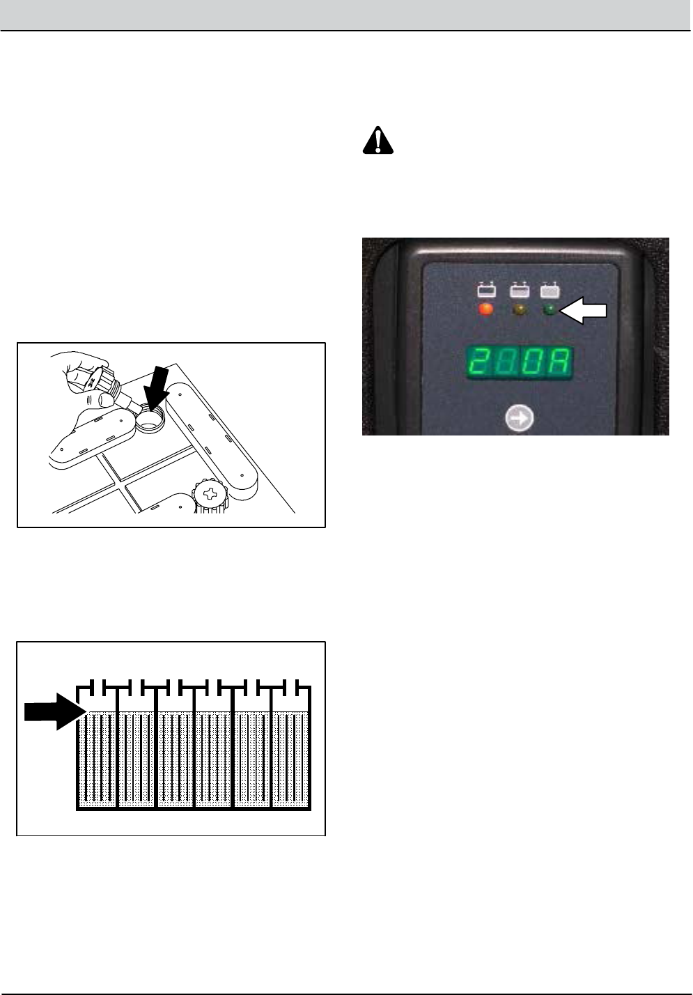
7. The green LED will go on when charging is
complete.
8. Unplug the on--board battery charger from the
wall outlet.
9. Neatly stow the on--board battery charger
cord inside the battery compartment.
10. Check the electrolyte level in each battery cell
after charging. If needed, add distilled water
to raise the electrolyte level to about 12mm
(0.4 in) below the bottom of the sight tubes.
11. Close the operator seat.
3-8 T16 Service Information 9008149 (1-11)
MAINTENANCE
CIRCUIT BREAKERS
Circuit breakers are resettable electrical circuit
protection devices designed to stop the ow of
current in the event of a circuit overload. Once a
circuit breaker is tripped, reset it manually by
pressing the reset button after the breaker has
cooled down.
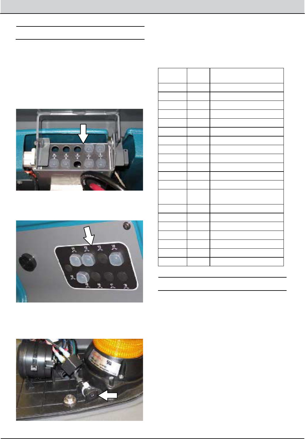
Circuit breakers 1 through 10 are located in the
front of the battery compartment.
Circuit breakers 11 through 19 are located on the
electrical panel.
Circuit breaker 20 is located inside the optional
light assembly mounted on top of the recovery
tank.
If the overload that caused the circuit breaker to
trip is still present, the circuit breaker will continue
to stop current ow until the problem is corrected.
The chart below shows the circuit breakers and
the electrical components they protect.
Circuit
Breaker Rating Circuit Protected
CB1 2.5 A Start
CB2 2.5 A Key switch
CB3 2.5 A Sweep controls (Option)
CB4 2.5 A Main water, FaST, ES, Horn
CB5 2.5 A Detergent meter (Option)
CB6 2.5 A Side brush (Option)
CB7 15 A FaST ./ ES pump (Option)
CB8 20 A Sweep brushes (Option)
CB9 2.5 A ec--H2O (Option)
CB10 2.5 A ec--H2O pump (Option)
CB11 15 A Lights (Option)
CB12 2.5 A Headlight / Tail lights (Option)
CB13 2.5 A Overhead guard warning light
(Option)
CB14 15 A Vacuum wand (Option)
CB15 2.5 A Warning lights (Option)
CB16 15 A Pre--Sweep (Option)
CB17 Open Extra for Specials
CB18 Open Extra for Specials
CB19 25 A Sweep vacuum fans (Option)
CB20 25 A Reverse alarm light (Option)
ELECTRIC MOTORS
Inspect the carbon brushes on the vacuum fan
motor after every 500 hours of operation. Inspect
the carbon brushes on the main brush motors,
Pre--Sweep main brush motor, and side brush
motors after the rst 1000 hours of operation and
every 100 hours after the initial check.
T16 Service Information 9008149 (1-11) 3-9
MAINTENANCE
SCRUB BRUSHES
The machine can be equipped with either disk or
cylindrical scrub brushes. Check scrub brushes
daily for wire or string tangled around the brush or
brush drive hub. Also check brushes or pads for
damage and wear.
DISK BRUSHES AND PADS
Replace the brushes or pads when they no longer
clean eectively.
Cleaning pads must be placed on pad drivers
before they are ready to use. The cleaning pad is
held in place with a center disk. Both sides of the
pad can be used for scrubbing. Turn the pad over
to use the other side.
Cleaning pads need to be cleaned immediately
after use with soap and water. Do not wash the
pads with a pressure washer. Hang pads, or lay
pads at to dry.
NOTE: Always replace brushes and pads in sets.
Otherwise one brush or pad will be more
aggressive than the other.
REPLACING DISK BRUSHES OR PAD
DRIVERS
1. Raise the scrub head.
2. Turn othe machine.
FOR SAFETY: Before leaving or servicing
machine, stop on level surface and turn o
machine.
3. Open the left side squeegee support door.
4. Turn the brushes until the spring handles are
visible.
5. Squeeze the spring handles and let the
brushes drop to the oor.
6. Push the new brush under the scrub head,
align the brush drive socket with the brush
drive hub, and lift the brush up onto the brush
drive hub.
7. Ensure the brush is securely mounted on the
brush drive hub.
8. Close and secure the left side squeegee
assembly.
9. Repeat procedure for the other brush.

3-10 T16 Service Information 9008149 (1-11)
MAINTENANCE
REPLACING DISK SCRUB PADS
1. Remove the pad driver from the machine.
2. Squeeze the spring clip together and remove
the center disk from the pad driver.
3. Remove the scrub pad from the pad driver.
4. Flip or replace the scrub pad. Center the
scrub pad on the pad driver and reinstall the
center disk to secure the pad in place on the
pad driver.
5. Reinstall the pad driver onto the machine.
T16 Service Information 9008149 (1-11) 3-11
MAINTENANCE
CYLINDRICAL BRUSHES
Rotate the brushes from front-to-rear after every
50 hours of operation.
Replace the brushes when they no longer clean
eectively.
NOTE: Replace worn brushes in pairs. Scrubbing
with brushes of unequal bristle length will result in
diminished scrubbing performance.
REPLACING CYLINDRICAL SCRUB BRUSHES
FOR SAFETY: Before leaving or servicing
machine, stop on level surface and turn o
machine.
1. Open the side squeegee support door.
2. Lift the idler plate retainer handle and unhook
the retainer ring from the idler plate hook.
3. Remove the idler plate from the scrub head.
4. Remove the brush from the scrub head
5. Position the brush with the double row end
towards the scrub head opening. Guide the
new brush onto the drive hub.
6. If rotating the existing brushes, only rotate
front to rear. Do NOT rotate end--for--end.
Before After
A
D
B
CA
D B
C
7. Reinstall the idler plate onto the scrub head
and secure the idler plate into place with the
idler plate retainer.
8. Repeat for the other brush on the other side
of the scrub head.
NOTE: Each side of the scrub head is stamped
with a letter. The idler door is stamped with the
same letter. Make sure the letter on the idler door
matches the letter on the scrub head when
reinstalling the doors.

3-12 T16 Service Information 9008149 (1-11)
MAINTENANCE
CHECKING CYLINDRICAL SCRUB BRUSH
PATTERN
FOR SAFETY: Before leaving or servicing
machine, stop on level surface and turn o
machine.
1. Apply chalk, or a similar marking material, to
a smooth and level section of oor.
NOTE: If chalk or other material is not available,
allow the brush to spin on the oor for two
minutes. A polish mark will remain on the oor.
2. Park the machine several feet behind the
chalked area and shut o the machine.
3. Press and hold the conguration mode button
while turning the key to the on position.
Continue holding the conguration mode
button until CONFIG MODE appears on the
LCD display. Release the conguration mode
button.
4. Press the Brush pressure button to enter the
machine conguration modes.
C1: Disk/Cyl Cyl should appear in the LCD
display.
5. Press the Contrast control button once to
scroll to C16: Dwn Pres Tst Disabled (Down
Pressure Test Disabled).

T16 Service Information 9008149 (1-11) 3-13
MAINTENANCE
6. Press the Brush pressure button to enter the
down pressure test selection mode.
C16: Dwn Pres Tst <Disabled (Down
Pressure Test Disabled) should appear on the
LCD display. The < symbol must appear in
front of Disabled .
7. Press the Contrast control button once to
select C16:Dwn Pres Tst <Enabled (Down
Pressure Test Enabled). The < symbol must
appear in front of Enabled.
8. Press the Brush pressure button to enable
the brush pressure test.
C16: Dwn Pres Tst Enabled should appear
on the LCD display. The <symbol should no
longer appear in front of Enabled
9. Turn the key to the o position to save the
Down Pressure Test Enabled mode and then
turn the key back to the on position to
continue with the procedure.
Note: Do Not turn o the machine second time
after the Down Pressure Test Enabled mode has
been saved. The entire procedure to get the
machine into the Down Pressure Test Mode will
need to be repeated if the machine is turned oa
second time.

3-14 T16 Service Information 9008149 (1-11)
MAINTENANCE
10. Press the 1-STEP button and then
immediately press one of the Solution on/o
buttons to shut o the solution supply and
prevent the brushes from getting wet.
11. Observe the solution ow indicator lights.
None of the indicator lights should be
illuminated.
12. Press the 1-STEP button to raise the scrub
head.
13. Position the machine over the chalked area.
14. Press the 1-STEP button to lower the scrub
head and allow the brushes to operate for 15
to 20 seconds. Keep the scrub head in one
spot in the chalked area.
NOTE: If necessary, press the Brush pressure
button to set the brush pressure to the medium
setting.
15. Press the 1--STEP button to raise the scrub
head and drive the machine away from the
chalked area.

T16 Service Information 9008149 (1-11) 3-15
MAINTENANCE
16. Observe the brush patterns. If the brush
pattern is the same width across the entire
length of each brush and both brushes are the
same width, no adjustment is necessary.
10355
17. If the brush patterns are tapered, see
ADJUSTING THE CYLINDRICAL BRUSH
TAPER section of this manual.
10652
18. The brush patterns should be 25 to 38 mm
(1 to 1.5 in) wide with the brushes in the
lowered position and both patterns should be
the same width. If the width of the brushes is
not the same, see ADJUSTING THE
CYLINDRICAL BRUSH WIDTH section of this
manual.
10653
19. Turn the key to the o position to return to
normal operation.
ADJUSTING CYLINDRICAL BRUSH TAPER
FOR SAFETY: Before leaving or servicing
machine, stop on level surface and turn o
machine.
1. Open the side squeegee support door.
2. Loosen the mounting screw on the idler door.
3. Raise or lower the end of the brush with the
smaller brush adjustment screw as necessary
to straighten the brush pattern.
4. Retighten the mounting screw on the idler
door.
5. Close the side squeegee support door.
6. Recheck the pattern. Readjust if necessary.
7. Repeat procedure for the other brush located
on other side of the scrub head.

3-16 T16 Service Information 9008149 (1-11)
MAINTENANCE
ADJUSTING CYLINDRICAL BRUSH PATTERN WIDTH
FOR SAFETY: Before leaving or servicing
machine, stop on level surface and turn o
machine.
1. Start the machine, completely lower the scrub
head, and turn o the machine.
2. Open the side squeegee support door.
3. Remove the debris trough
4. Loosen the lock nut located behind the
bracket.
5. Turn the adjustment nut to adjust the
cylindrical brush pattern width. Lengthen the
scrub head link to increase the rear brush pattern
width. Shorten the scrub head link to increase
the front brush pattern.
NOTE: Two full turns of the scrub head link
adjustment bolt will change the brush pattern
approximately 25 mm (1 in).
6. Retighten the lock nut located against the
bracket.
7. Recheck the pattern. Readjust if necessary.
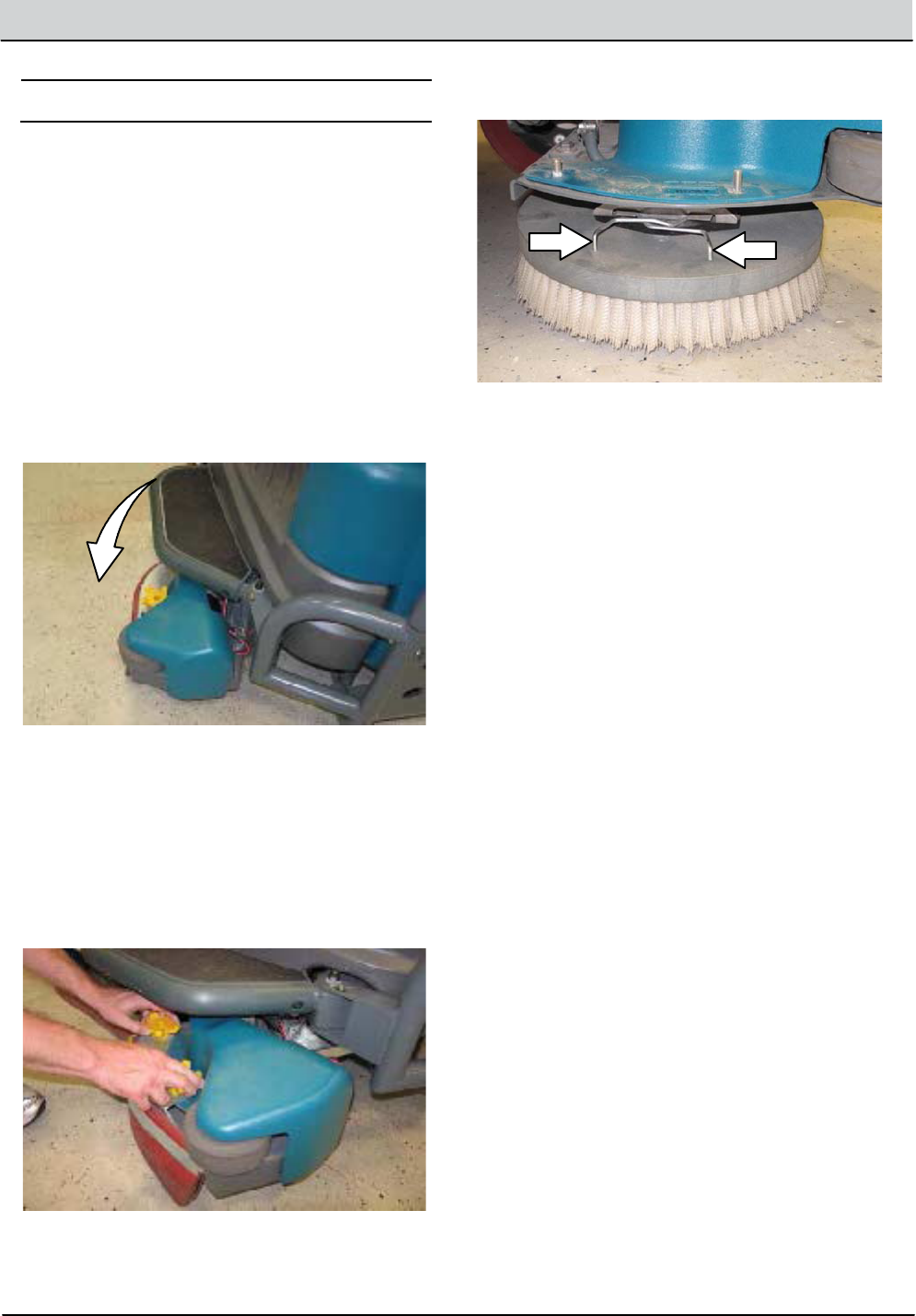
T16 Service Information 9008149 (1-11) 3-17
MAINTENANCE
SIDE BRUSH (OPTION)
Check the side brush daily for wear or damage.
Remove any tangled string or wire from the side
brush or side brush drive hub.
REPLACING THE SIDE BRUSH
Replace the brush when it no longer cleans
eectively.
1. Start the machine and press the side brush
switch.
2. Shut o the machine after the side brush
rotates from under the side guard, but before
the side brush assembly lowers to the oor.
FOR SAFETY: Before leaving or servicing
machine, stop on level surface and turn o
machine.
3. Remove the knobs holding the side brush
squeegee assembly to the machine and
remove the squeegee assembly from the
machine.
4. Squeeze the spring handles and let the side
brush drop to the oor.
5. Remove the side brush from under the side
brush assembly.
6. Place the new side brush underneath the side
brush assembly and lift the side brush up onto
the side brush hub until the brush locks onto
the hub.
7. Reinstall the side brush squeegee assembly
onto the side brush assembly.
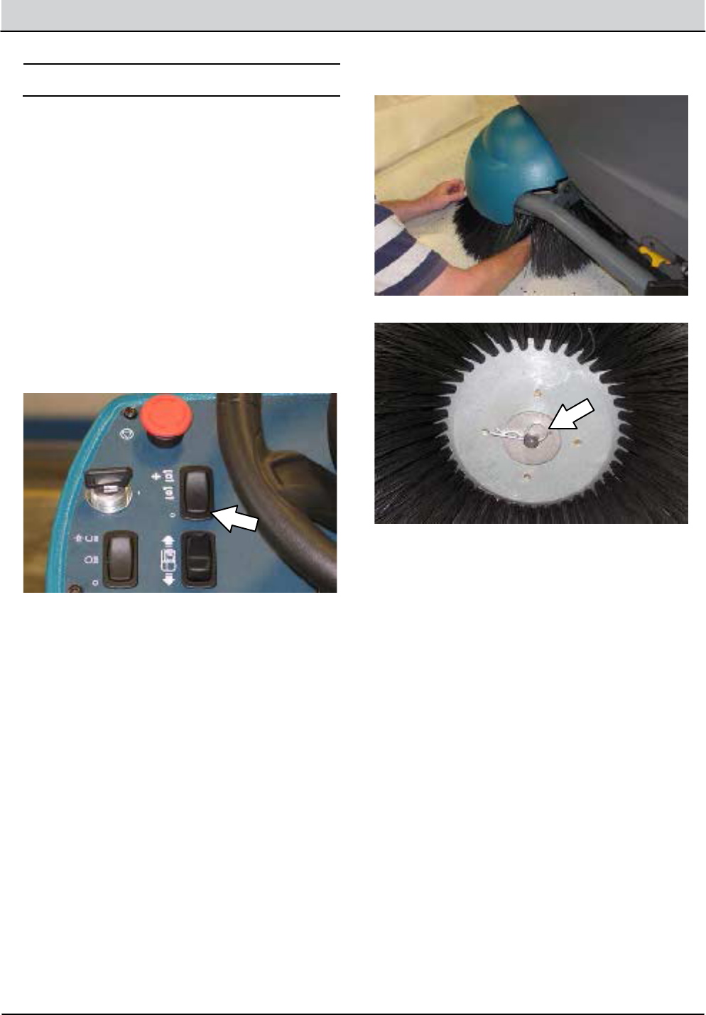
3-18 T16 Service Information 9008149 (1-11)
MAINTENANCE
PRE--SWEEP BRUSHES
The Pre--Sweep assembly is equipped with disk
side brushes and a cylindrical main brush. Check
the brushes daily for wire or string tangled around
the brush or brush drive hub. Check the brushes
daily for damage and wear.
REPLACING THE PRE--SWEEP DISK
BRUSHES
Replace the brushes when they no longer clean
eectively.
1. Turn on the machine.
2. Press the bottom of the Pre--Sweep switch
to raise the Pre--Sweep assembly and stop
sweeping.
3. Turn o the machine.
FOR SAFETY: Before leaving or servicing
machine, stop on level surface and turn o
machine.
4. Reach into the center of the brush and pull
the cotter pin from the hub assembly.
5. Remove the side brush from under the
Pre--Sweep assembly.
6. Install the new side brush onto the
Pre--Sweep side brush assembly.

T16 Service Information 9008149 (1-11) 3-19
MAINTENANCE
REPLACING THE PRE--SWEEP CYLINDRICAL
BRUSH
Replace the brush when it no longer cleans
eectively.
FOR SAFETY: Before leaving or servicing
machine, stop on level surface and turn o
machine.
1. Turn o the machine.
2. Open the Pre--Sweep assembly cover and
lock the cover open.
3. Loosen and remove the left brush arm knob.
4. Remove the left brush arm.
5. Remove the three knobs holding the
Pre--Sweep side skirt and side skirt plate to
the Pre--Sweep assembly.
6. Remove the side skirt plate and side skirt
from the Pre--Sweep assembly.
7. Remove the cylindrical brush and replace with
a new brush.
8. Guide the slotted end of the new brush onto
the drive hub.
9. Reinstall the side skirt, side skirt plate, and
left brush arm.
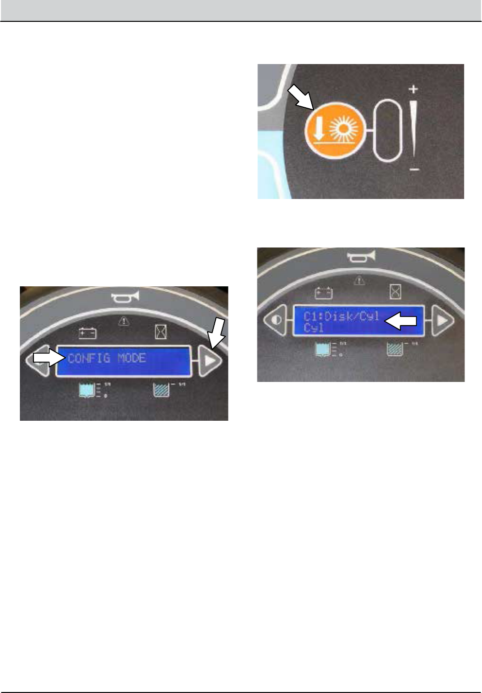
3-20 T16 Service Information 9008149 (1-11)
MAINTENANCE
CHECKING AND ADJUSTING PRE-SWEEP
CYLINDRICAL BRUSH PATTERN
FOR SAFETY: Before leaving or servicing
machine, stop on level surface and turn o
machine.
1. Apply chalk, or a similar marking material, to
a smooth and level section of the oor.
NOTE: If chalk or other material is not available,
allow the brush to spin on the oor for two
minutes. A polish mark will remain on the oor.
2. Park the machine several feet behind the
chalked area and shut o the machine.
3. Press and hold the conguration mode button
while turning the key to the on position.
Continue holding the Conguration mode
button until CONFIG MODE appears on the
LCD display. Release the conguration mode
button.
4. Press the Brush pressure button to enter the
machine conguration modes.
C1: Disk/Cyl Cyl should appear in the LCD
display.

T16 Service Information 9008149 (1-11) 3-21
MAINTENANCE
5. Press the Contrast control button once to
scroll to C16: Dwn Pres Tst Disabled (Down
Pressure Test Disabled).
6. Press the Brush pressure button to enter the
down pressure test selection mode.
C16: Dwn Pres Tst <Disabled (Down
Pressure Test Disabled) should appear on the
LCD display. The < symbol must appear in
front of Disabled .
7. Press the Contrast control button once to
select C16:Dwn Pres Tst<Enabled (Down
Pressure Test Enabled). The < symbol must
appear in front of Enabled.

3-22 T16 Service Information 9008149 (1-11)
MAINTENANCE
8. Press the the Brush pressure button to enable
the brush pressure test.
C16: Dwn Pres Tst Enabled should appear
on the LCD display. The < symbol should no
longer appear in front of Enabled.
9. Turn the key to the o position to save the
Down Pressure Test Enabled mode and then
turn the key back to the on position to
continue with the procedure.
NOTE: Do Not turn o the machine a second time
after the Down Pressure Test Enabled mode has
been saved. The entire procedure to get the
machine into the Down Pressure Test Mode will
need to be repeated if the machine is turned o a
second time.
10. Press the 1-STEP button and then
immediately press one of the Solution on/o
buttons to shut o the solution supply.
11. Observe the solution ow indicator lights.
None of the indicator lights should be
illuminated.

T16 Service Information 9008149 (1-11) 3-23
MAINTENANCE
12. Center the Pre--Sweep assembly over the
chalked area on the oor.
13. Press the Pre-Sweep switch to the middle
position. The Pre--Sweep assembly will
lower and the brush will begin spinning.
14. Press the bottom of the Pre-Sweep switch to
shut o the Pre--sweep system. The
Pre--Sweep brush will stop spinning and the
Pre--Sweep assembly will raise to the o
position.
15. Drive the machine away from the chalked
area.
16. Observe the shape of the brush pattern. If the
brush pattern has parallel sides, the brush
does not need adjustment.
10355
17. If the brush pattern is tapered, the brush
needs adjustment to straighten the brush
pattern.
10356
18. To adjust the brush taper, loosen the nut on
the arm adjustment plate.
19. Press the Pre-Sweep switch to the middle
position. Allow the brush to oat in place for
15 to 20 seconds.
20. Tighten the nut on the arm adjustment plate.
21. Check the brush pattern again and readjust
as necessary until the width of the pattern is
the same along the length of the brush
pattern.
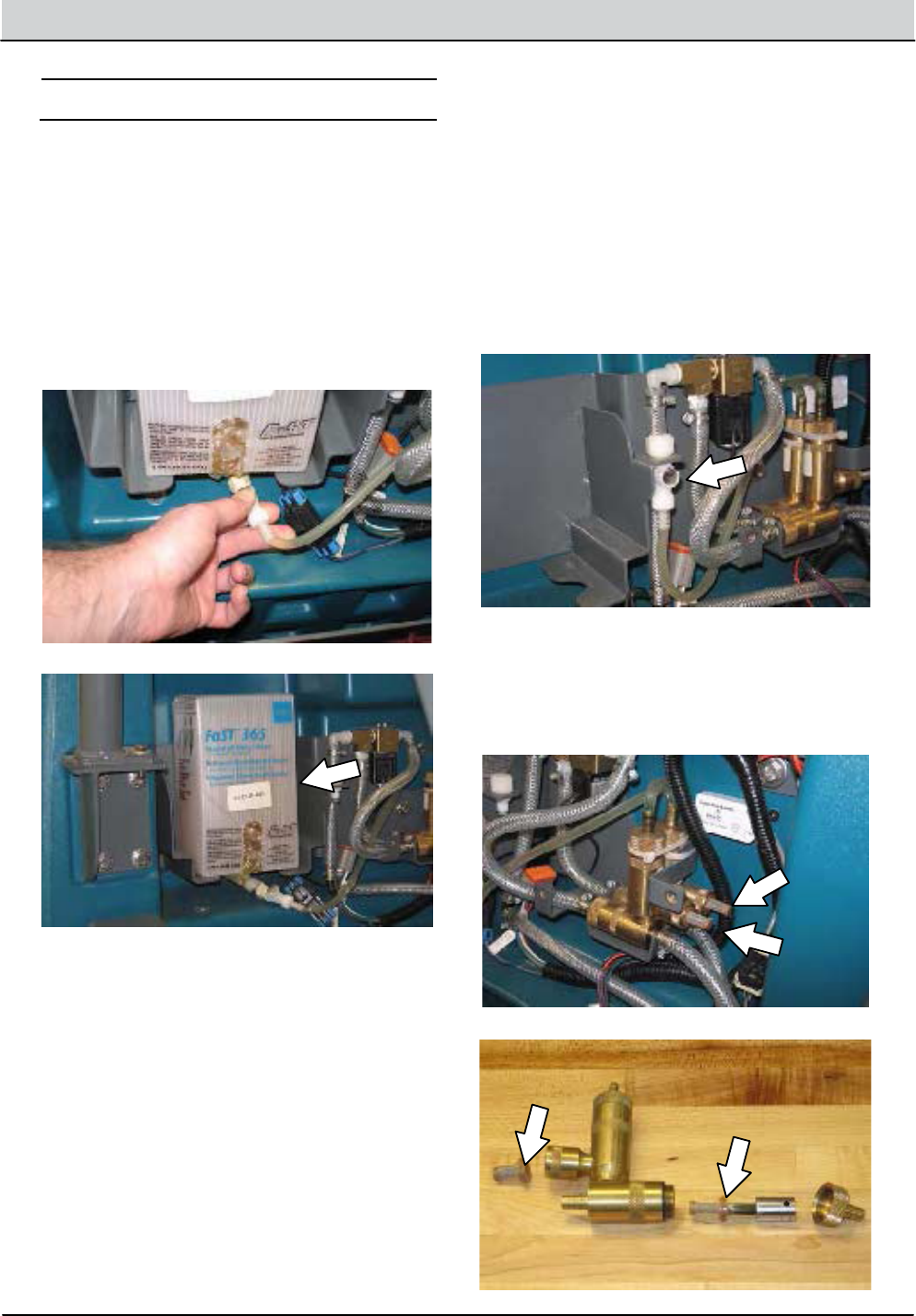
3-24 T16 Service Information 9008149 (1-11)
MAINTENANCE
FaST SYSTEM
REPLACING THE FaST--PAK CARTON
FOR SAFETY: Before leaving or servicing
machine, stop on level surface and turn o
machine.
1. Lift the operator seat open and engage the
seat support bar.
2. Squeeze the button on the FaST supply hose
connector, then pull the empty FaST--PAK
carton out from the compartment and discard.
3. Remove the perforated knock outs from the
new FaST--PAK carton. DO NOT remove the
bag from the carton. Pull the hose connector
from the bottom of the bag and remove the
hose cap from the connector.
NOTE: The FaST--PAK Floor Cleaning
Concentrate is specially designed for use with the
FaST system scrubbing application. NEVER use
a substitute. Other cleaning solutions may cause
FaST system failure.
4. Slide the FaST--PAK carton into the
FaST--PAK bracket.
5. Connect the FaST supply hose to the
FaST--PAK hose connector.
6. Scrub with the FaST system for a few
minutes to allow the detergent to reach
maximum foaming.
CLEANING THE FaST SUPPLY HOSE
CONNECTOR
Soak the connector in warm water if detergent
buildup is visible. When a FaST--PAK carton is not
installed, store the supply hose connector on the
storing plug to prevent the hose from clogging.
REPLACING THE FaST INJECTOR FILTERS
Replace the FaST injector lters after every 1000
hours of operation. Empty the solution tank before
replacing the lters.

T16 Service Information 9008149 (1-11) 3-25
MAINTENANCE
ec- H2O MODULE FLUSH PROCEDURE
This procedure is only required when an alarm
sounds and the ec--H2O system indicator light
begins to blink.
FOR SAFETY: Before leaving or servicing
machine, stop on level surface and turn o
machine.
1. Lift the operator seat open and engage the
seat support bar.
2. Remove the ec--H2O compartment cover.
3. Remove the drain hose from the ec--H2O
compartment.
4. Disconnect the outlet hose from the hose
connected to the ec--H2O manifold.
5. Connect the drain hose to the ec--H2O
manifold hose disconnected from the outlet
hose in the previous step.
6. Place the drain hose into a empty container.
7. Pour 2 gallons (7.6 liters) of white or rice
vinegar into the solution tank.
FOR SAFETY: Wear protective gloves and eye
protection when handling vinegar.

3-26 T16 Service Information 9008149 (1-11)
MAINTENANCE
8. Turn the key to the on ( I ) position.
9. Press and release the ec--H2O module ush
switch to start the ush cycle.
NOTE: The module will automatically shut o
when the ush cycle is complete (approximately 7
minutes). The module must run the full 7 minute
cycle in order to reset the system indicator light
and alarm.
10. Pour 2 gallons (7.6 liters) of cool clean water
into the solution tank.
11. Press and release the ush switch to rinse
any remaining vinegar from the module. After
1--2 minutes, press the ush switch to turn o
the module.
12. Disconnect the drain hose from the ec--H2O
manifold hose.
13. Reconnect the outlet hose to the the scrub
head to the ec--H2O manifold hose.
14. Place the drain hose back into the ec--H2O
compartment.
15. Reinstall the ec--H2O compartment cover.
16. Close the operator seat cover.

T16 Service Information 9008149 (1-11) 3-27
MAINTENANCE
SQUEEGEE BLADES
Check the squeegee blades for damage and wear
daily. When the blades become worn, rotate the
blades end--for--end or top--to--bottom to a new
wiping edge. Replace blades when all edges are
worn.
Check the deection of the squeegee blades daily
or when scrubbing a dierent type of surface.
Check the leveling of the rear squeegee every 50
hours of operation.
REPLACING (OR ROTATING) THE REAR
SQUEEGEE BLADES
1. Lower the scrub head.
FOR SAFETY: Before leaving or servicing
machine, stop on level surface and turn o
machine.
2. Disconnect the vacuum hose from the rear
squeegee assembly.
3. Loosen both squeegee mounting handles.
4. Pull the rear squeegee assembly from the
machine.
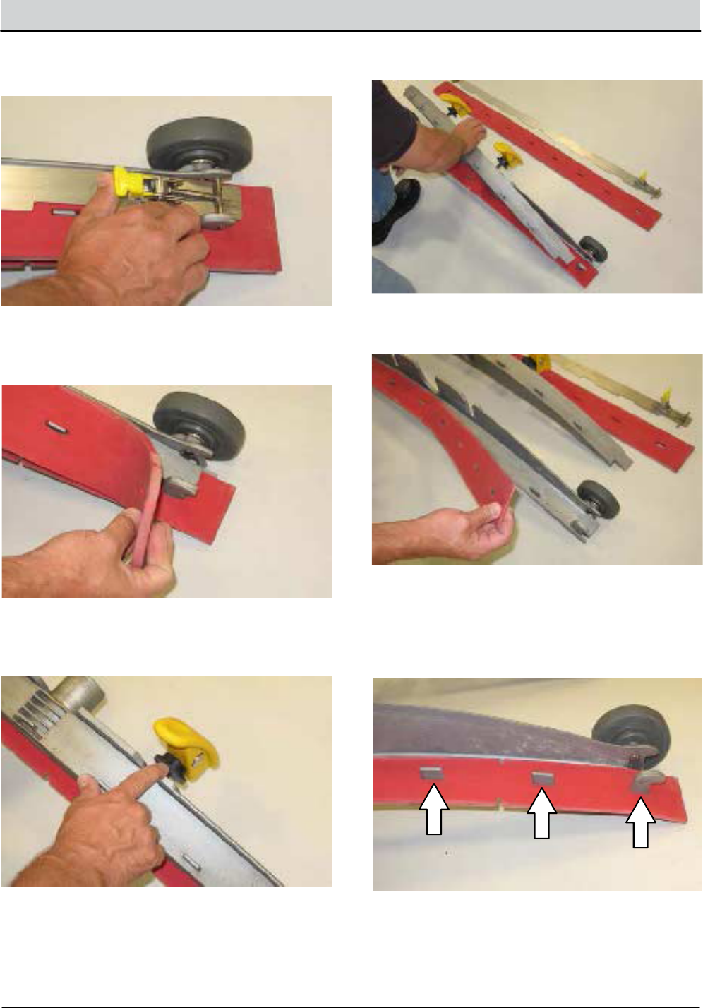
3-28 T16 Service Information 9008149 (1-11)
MAINTENANCE
5. Loosen the rear squeegee retainer latch and
remove the retainer from the squeegee assembly.
6. Remove the squeegee from the squeegee
assembly.
7. Slide both retainers out away from the
squeegee assembly.
8. Remove the inner frame from the outer frame.
9. Remove the squeegee from the outer frame.
10. Install the rotated or new squeegee blade into
the outer frame. Be sure the squeegee is
completely slid down onto each tab on the
outer frame.
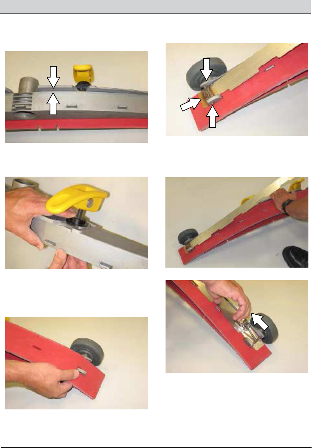
T16 Service Information 9008149 (1-11) 3-29
MAINTENANCE
11. Install the inner frame over the squeegee and
onto the outer frame. Be sure the inner frame
is tight against the top of the outer frame.
12. Slide both retainers into the squeegee
assembly.
13. Place the rotated or new squeegee blade onto
the inner frame. Be sure the squeegee is
securely attached on each tab on the inner
frame.
14. Insert the hinge end of the retainer into the
hooks in the inner frame.
15. Install the retainer along the rest of the
squeegee assembly and fasten the latch onto
the other end of the squeegee assembly.

3-30 T16 Service Information 9008149 (1-11)
MAINTENANCE
LEVELING THE REAR SQUEEGEE
Leveling the squeegee ensures the entire length
of the squeegee blade is in even contact with the
surface being scrubbed. Perform this adjustment
on an even and level oor.
1. Lower the squeegee and drive the machine
several meters (feet) forward and slowly bring
the machine to a stop.
FOR SAFETY: Before leaving or servicing
machine, stop on level surface and turn o
machine.
2. Check the squeegee deection over the full
length of the squeegee blade.
3. If the deection is not the same over the full
length of the blade, use the tilt adjust knob to
make adjustments.
DO NOT disconnect the vacuum hose from
the squeegee frame when leveling squeegee.
4. To adjust the squeegee leveling, loosen the tilt
lock knob.
5. Turn the squeegee tilt adjust knob
counter-clockwise to decrease the deection
at the ends of the squeegee blade.
Turn the squeegee tilt adjust knob clockwise
to increase the deection at the ends of the
squeegee blade.
6. Tighten the tilt lock knob.
7. Drive the machine forward with the squeegee
down to recheck the squeegee blade
deection if adjustments were made.
8. Readjust the squeegee blade deection if
necessary.

T16 Service Information 9008149 (1-11) 3-31
MAINTENANCE
ADJUSTING THE REAR SQUEEGEE BLADE
DEFLECTION
Deection is the amount of curl the overall
squeegee blade has when the machine moves
forward. The best deection is when the
squeegee wipes the oor dry with a minimal
amount of deection.
NOTE: Make sure the squeegee is level before
adjusting the deection. See LEVELING THE
REAR SQUEEGEE.
1. Lower the squeegee and drive the machine
several meters (feet) forward and slowly bring
the machine to a stop.
FOR SAFETY: Before leaving or servicing
machine, stop on level surface and turn o
machine.
2. Look at the amount of deection or “curl” of
the squeegee blade. The correct amount of
deection is 12 mm (0.50 in) for scrubbing
smooth oors and 15 mm (0.62 in) for rough
oors.
3. To adjust the overall squeegee blade
deection, loosen the lock knob.
4. Turn the adjustment knobs counterclockwise
to increase deection or clockwise to
decrease deection.
5. Retighten the lock knob.
6. Drive the machine forward again to recheck
the squeegee blade deection.
7. Readjust the squeegee blade deection if
necessary.

3-32 T16 Service Information 9008149 (1-11)
MAINTENANCE
REPLACING OR ROTATING THE SIDE
SQUEEGEE BLADES
1. If necessary, raise the scrub head.
FOR SAFETY: Before leaving or servicing
machine, stop on level surface and turn o
machine.
2. Open the side squeegee support door.
3. Unhook the retaining band latch from the side
squeegee assembly.
4. Remove the retaining band from the side
squeegee assembly.
5. Remove the squeegee from the side
squeegee assembly.
6. Install the rotated or new rear squeegee blade
onto the side squeegee assembly.
7. Hook the retaining band onto the side
squeegee assembly.
8. Fasten the retaining band latch onto the side
squeegee assembly.
9. Repeat for the side squeegee on the other
side of the scrub head.

T16 Service Information 9008149 (1-11) 3-33
MAINTENANCE
REPLACING OR ROTATING THE SIDE
BRUSH SQUEEGEE BLADE(S) (OPTION)
Check the side brush squeegee blade for damage
and wear daily. Replace or rotate the blade if the
leading edge is torn or worn half-way through the
thickness of the blade.
1. Start the machine and press the side brush
switch.
2. Shut othe machine after the side brush
rotates from under the side guard, but before
the side brush assembly lowers to the oor.
FOR SAFETY: Before leaving or servicing
machine, stop on level surface and turn o
machine.
3. Remove the knobs holding the side brush
squeegee assembly to the machine and
remove the squeegee assembly.
4. Loosen the retaining band latch.
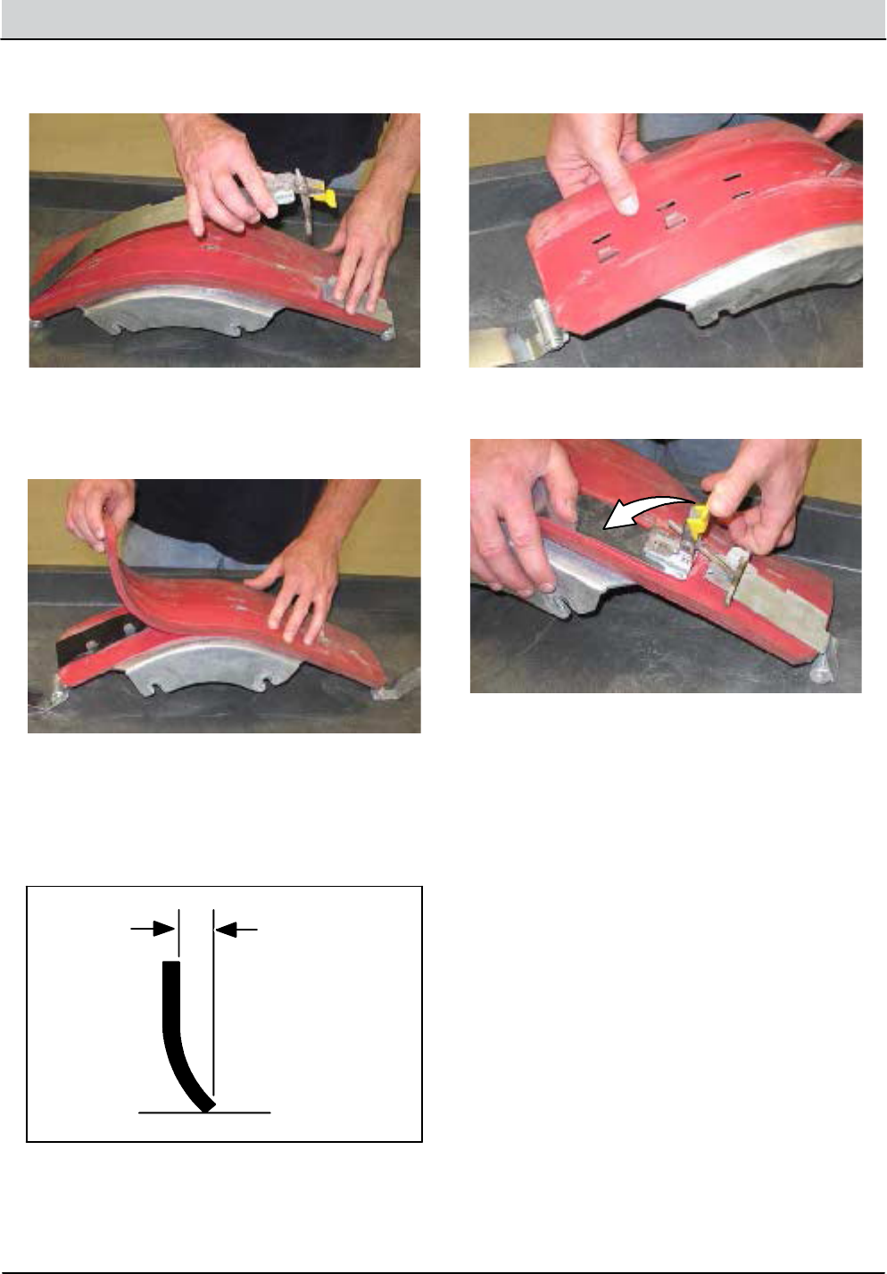
3-34 T16 Service Information 9008149 (1-11)
MAINTENANCE
5. Remove the squeegee blade(s) and retainer
from the squeegee frame.
NOTE: Observe which squeegee slots were
installed on the squeegee frame before removing
the squeegee.
NOTE: Brush wear may aect squeegee
deection. Install / reinstall squeegees so the
deection is approximately 12 mm (0.50 in) for
smooth oors and 15 mm (0.62 in) for rough
oors.
6. Install the rotated / new squeegee blade(s)
and retainer onto the side brush assembly.
7. Fasten the side brush retaining band latch.
8. Reinstall the side brush squeegee assembly
onto the side brush assembly.

T16 Service Information 9008149 (1-11) 3-35
MAINTENANCE
SKIRTS AND SEALS
PRE--SWEEP SIDE SKIRTS (OPTION)
The side skirts are located on both sides of the
Pre--Sweep assembly. The side skirts should be
just touching the oor.
Check the skirts for damage and wear after every
50 hours of operation.
PRE--SWEEP RECIRCULATION SKIRT
(OPTION)
The Pre--Sweep recirculation skirt is located
behind the main sweeping brush.
Check the skirt for damage and wear after every
50 hours of operation.
PRE--SWEEP REAR SKIRT (OPTION)
The Pre--Sweep rear skirt is located behind the
recirculation skirt and main sweeping brush.
Check the skirt for damage and wear after every
50 hours of operation.

3-36 T16 Service Information 9008149 (1-11)
MAINTENANCE
BELTS AND CHAINS
STEERING CHAIN
The steering chain is located on the steering
column directly under the control panel. There
should be no slack in the chain. Check the
steering chain tension after every 200 hours.
CYLINDRICAL BRUSH DRIVE BELTS
The brush drive belts are located on the
cylindrical brush scrub head. Check the belts for
damage and wear after every 200 hours of
operation.
PRE--SWEEP BRUSH DRIVE BELT (OPTION)
The Pre--Sweep brush drive belt is located inside
the Pre--Sweep assembly on the right side of the
cylindrical brush. Check the belt for damage and
wear after every 200 hours of operation.
TIRES
The machine has three solid rubber tires: one in
front, and two in the rear of the machine. Check
tires for damage and wear after every 500 hours
of operation.
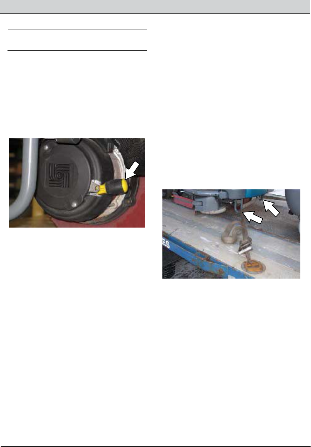
T16 Service Information 9008149 (1-11) 3-37
MAINTENANCE
PUSHING, TOWING, AND TRANSPORTING
THE MACHINE
PUSHING OR TOWING THE MACHINE
If the machine becomes disabled, it can be
pushed or towed from the front or rear.
The parking brake must be disabled before towing
or pushing the machine. To disable the brake,
insert the tip of a small screw driver between the
electronic brake lever and the hub. The machine
can move freely when the parking brake is
disabled.
Only push or tow the machine for a very short
distance and do not exceed 3.2 kp/h (2 mph). It is
NOT intended to be pushed or towed for a long
distance or at a high speed.
ATTENTION! Do not push or tow machine for
a long distance or damage may occur to the
propelling system.
Immediately after pushing the machine, remove
the screw driver from between the electronic
brake lever and the hub. NEVER operate the
machine with the parking brake disabled.
FOR SAFETY: Do not operate machine with
brake disabled.
TRANSPORTING THE MACHINE
1. Position the machine at the loading edge of
the truck or trailer.
FOR SAFETY: Use truck or trailer that will
support the weight of the machine.
NOTE: Empty the recovery and solution tanks
before transporting the machine.
2. If the loading surface is not horizontal or is
higher than 380 mm (15 in) from the ground,
use a winch to load machine.
If the loading surface is horizontal AND is
380 mm (15 in) or less from the ground, the
machine may be driven onto the truck or
trailer.
3. To winch the machine onto the truck or trailer,
attach the winching chains to the stabilizer
legs.
FOR SAFETY: When unloading machine o
truck or trailer, use winch. Do not drive the
machine othe truck or trailer unless the
loading surface is horizontal AND 380 mm
(15 in) or less from the ground.
4. Position the machine onto the truck or trailer
as far as possible. If the machine starts to
veer othe center line of the truck or trailer,
stop and turn the steering wheel to center the
machine.

3-38 T16 Service Information 9008149 (1-11)
MAINTENANCE
5. Lower the scrub head and block the machine
tires. Tie down the machine to the truck or
trailer before transporting.
The front tie-down locations are the stabilizer
legs.
The rear tie-down locations are the holes in
the frame.
6. If the loading surface is not horizontal or is
higher than 380 mm (15 in) from the ground,
use a winch to unload machine.
If the loading surface is horizontal AND is
380 mm (15 in) or less from the ground, the
machine may be driven othe truck or trailer.
FOR SAFETY: When unloading machine o
truck or trailer, use winch. Do not drive the
machine othe truck or trailer unless the
loading surface is horizontal AND 380 mm
(15 in) or less from the ground.
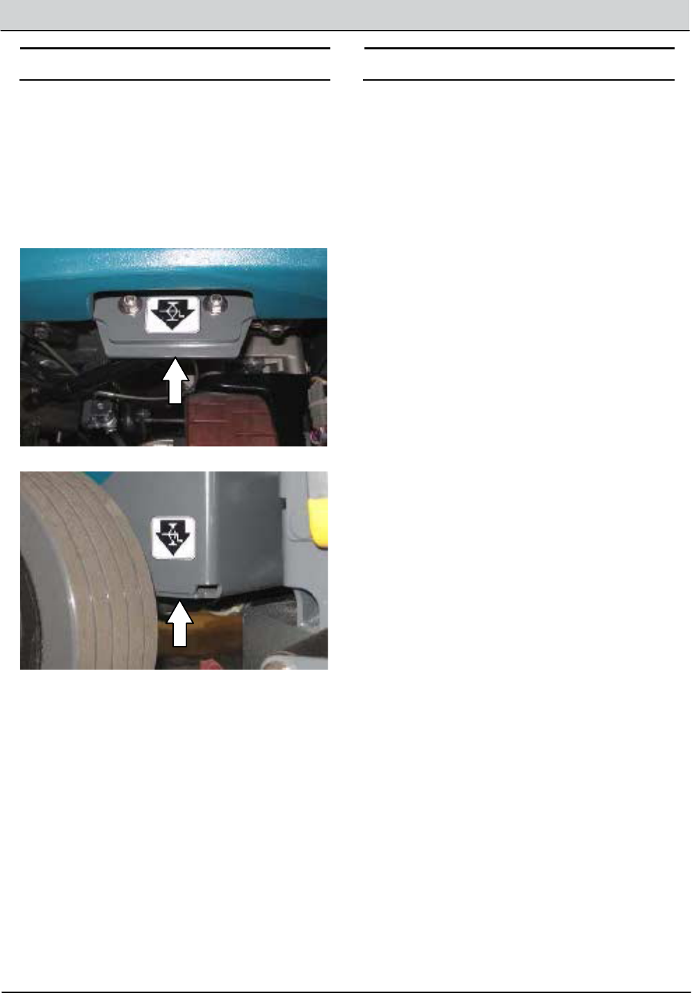
T16 Service Information 9008149 (1-11) 3-39
MAINTENANCE
MACHINE JACKING
FOR SAFETY: Before leaving or servicing
machine, stop on level surface.
Empty the recovery and solution tanks before
jacking the machine. Jack up the machine from
underneath the jack point at the front of the
machine and the two jack points located near the
rear tires at the back of the machine. Use a hoist
or jack that will support the weight of the machine.
Always stop the machine on a at level surface
and block the tires before jacking the machine up.
FOR SAFETY: When servicing machine, block
machine tires before jacking machine up. Use
a hoist or jack that will support the weight of
the machine. Jack machine up at designated
locations only. Support machine with jack
stands.
STORAGE INFORMATION
The following steps should be taken when storing
the machine for extended periods of time.
1. Drain and clean the solution and recovery
tanks.
2. Park the machine in a cool, dry area indoors.
Do not expose the machine to rain.
3. Remove the batteries, or charge them every
three months.

3-40 T16 Service Information 9008149 (1-11)
MAINTENANCE
FREEZE PROTECTION (MACHINES WITHOUT
OPTIONAL ec--H2O SYSTEM)
FOR SAFETY: Before leaving or servicing
machine, stop on level surface and turn o
machine.
1. Machines equipped with FaST: Remove the
FaST--PAK.
2. Completely drain the solution tank and
recovery tank.
3. Disconnect the hose from the solenoid valve
inlet port located on the bottom of the frame
and allow all remaining solution to drain from
the system.
4. Use between 13.8 -- 27.6 kPa (2 -- 4 psi) of
compressed air to blow remaining solution
from the disconnected hose.
FOR SAFETY: Wear eye and ear protection
when using pressurized air or water.
5. Reconnect the hose to the solenoid valve inlet
port.
6. Pour 7.6 L (2 gal) of Propylene Glycol Based /
Recreational Vehicle (RV) antifreeze into the
solution tank.
7. Turn on the machine
8. Press the 1--STEP button.
9. Repeatedly press the Solution increase button
(+) until the solution ow is at the highest
setting.
10. Drive the machine to circulate the RV
antifreeze com pletely through the system.
11. Press the 1--STEP button to turn o the
system.
12. Machines equipped with the optional
spray nozzle only: Operate the wand for a
few seconds to protect the pump.
13. Turn o the machine.
14. The remaining RV antifreeze does not need to
be drained from the solution tank.

T16 Service Information 9008149 (1-11) 3-41
MAINTENANCE
PREPARING THE MACHINE FOR OPERATION
(MACHINES WITHOUT OPTIONAL ec--H2O
SYSTEM)
All Propylene Glycol Based / Recreational Vehicle
(RV) Antifreeze must be completely cleaned from
the scrubbing system before the machine can be
used for scrubbing.
FOR SAFETY: Before leaving or servicing
machine, stop on level surface and turn o
machine.
1. Completely drain all Propylene Glycol Based /
Recreational Vehicle (RV) antifreeze from the
solution tank.
2. Rinse out the solution tank. Refer to
DRAINING AND CLEANING THE SOLUTION
TANK in the OPERATOR’S MANUAL for
instructions how to clean the solution tank.
3. Pour 11.4 L (3 gal) of cool clean water into the
solution tank.
4. Turn on the machine
5. Press the 1--STEP button.
6. Repeatedly press the Solution increase button
(+) until the solution ow is at the highest
setting.
7. Drive the machine to circulate the clean water
completely through the systemto clean out
the RV antifreeze.
8. Press the 1--STEP button to turn o the
system.
9. Machines equipped with the optional
spray nozzle only: Operate the wand for a
few seconds to clean the RV antifreeze from
the pump.
10. Turn o the machine.
11. The remaining water does not need to be
drained from the solution tank.
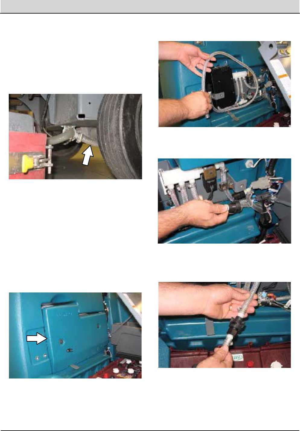
3-42 T16 Service Information 9008149 (1-11)
MAINTENANCE
FREEZE PROTECTION (MACHINES WITH
OPTIONAL ec--H2O SYSTEM)
1. Completely drain the solution tank and
recovery tank.
2. Disconnect the hose from the solenoid valve
inlet port located on the bottom of the frame
and allow all remaining solution to drain from
the system.
3. Use between 13.8 -- 27.6 kPa (2 -- 4 psi) of
compressed air to blow remaining solution
from the disconnected hose.
FOR SAFETY: Wear eye and ear protection
when using pressurized air or water.
4. Reconnect the hose to the solenoid valve inlet
port.
5. Lift the operator seat open and engage the
seat support bar.
6. Remove the ec--H2O compartment cover.
7. Remove the drain hose from the ec--H2O
compartment.
8. Disconnect the outlet hose to the scrub head
from the ec--H2O manifold hose.
9. Connect the drain hose to the ec--H2O
manifold hose disconnected from the outlet
hose in the previous step.

T16 Service Information 9008149 (1-11) 3-43
MAINTENANCE
10. Pour 7.6 L (2 gal) of Propylene Glycol Based /
Recreational Vehicle (RV) antifreeze into the
solution tank.
11. Place the ec--H2O system outlet hose into an
empty container.
12. Press and release the ush switch on the
ec--H2O module to cycle the RVantifreeze
through ec--H2O system. When the antifreeze
appears in the container, press the switch
again to turn o the module.
13. Disconnect the drain hose from the ec--H2O
manifold hose.
14. Reconnect the outlet hose to the scrub head
to the ec--H2O manifold hose.
15. Place the drain hose back into the ec--H2O
compartment.
16. Reinstall the ec--H2O compartment cover.
17. Close the operator seat cover.
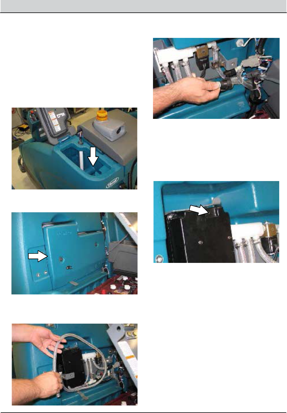
3-44 T16 Service Information 9008149 (1-11)
MAINTENANCE
PRIMING THE ec-H2O SYSTEM
Prime the ec--H2O system if the machine has
been stored for a long period with no water in the
solution tank / ec--H2O system.
FOR SAFETY: Before leaving or servicing
machine, stop on level surface and turn o
machine.
1. Fill the solution tank with clean cool water.
See FILLING THE SOLUTION TANK section
of the OPERATOR’S MANUAL.
2. Remove the ec--H2O compartment cover.
3. Remove the drain hose from the ec--H2O
compartment.
4. Disconnect the outlet hose to the scrub head
from the ec--H2O manifold hose.
5. Place the drain hose into an empty container.
6. Turn on the machine.
7. Press and release the ec--H2O module ush
switch. Allow the system to drain water into
the container for 2 minutes.
8. Press the ec--H2O module ush switch to
shut othe system.
9. Disconnect the drain hose from the ec--H2O
manifold hose.
10. Reconnect the outlet hose to the scrub head
to ec--H2O manifold hose.
11. Place the drain hose back into the ec--H2O
compartment.
12. Reinstall the ec--H2O compartment cover.
13. Close the operator seat cover.

Troubleshooting
Onboard Diagnostics . . . . . . . . . . . . . . . . . . . . . . . 4-2
Self-Test Mode .......................... 4-2
Conguration Mode . . . . . . . . . . . . . . . . . . . . . 4-4
LCD Warnings ........................... 4-6
LCD Faults .............................. 4-7
Propel Diagnostic Mode . . . . . . . . . . . . . . . . . 4-9
Curtis 1234 Controller Diagnostics . . . . . . 4-11
Diagnostic LED Operation . . . . . . . . . . . 4-11
Diagnostic Codes . . . . . . . . . . . . . . . . . . . 4-12
Input Display Mode . . . . . . . . . . . . . . . . . . . . 4-20
Manual Mode ..........................4-22
Battery Charger, Standard . . . . . . . . . . . . . . 4-24
Operation ...........................4-24
Conguration .......................4-24
Faults ...............................4-24
Battery Charger, Onboard Option . . . . . . . 4-25
Operation ...........................4-25
Conguration, Lead-Acid/Gel . . . . . . . . 4-25
Faults ...............................4-25
Subsystem Troubleshooting . . . . . . . . . . . . . . . 4-26
Back-Up Alarm/Light . . . . . . . . . . . . . . . . . . . 4-26
Electrical Schematic . . . . . . . . . . . . . . . . . 4-26
Troubleshooting . . . . . . . . . . . . . . . . . . . . 4-27
Battery Charging . . . . . . . . . . . . . . . . . . . . . . . 4-28
Electrical Schematic, Onboard . . . . . . . 4-28
Troubleshooting . . . . . . . . . . . . . . . . . . . . 4-29
Electrical Schematic, O Board . . . . . . . 4-30
Troubleshooting . . . . . . . . . . . . . . . . . . . . 4-31
Parking Brake, Electromagnetic . . . . . . . . . 4-32
Electrical Schematic . . . . . . . . . . . . . . . . . 4-32
Troubleshooting . . . . . . . . . . . . . . . . . . . . 4-33
Detergent Metering . . . . . . . . . . . . . . . . . . . . 4-34
Electrical Schematic . . . . . . . . . . . . . . . . . 4-34
Troubleshooting . . . . . . . . . . . . . . . . . . . . 4-35
Extended Scrub ........................4-36
Electrical Schematic . . . . . . . . . . . . . . . . . 4-36
Troubleshooting . . . . . . . . . . . . . . . . . . . . 4-37
Lighting ...............................4-38
Electrical Schematic . . . . . . . . . . . . . . . . . 4-38
Troubleshooting . . . . . . . . . . . . . . . . . . . . 4-39
Main Scrub Brushes . . . . . . . . . . . . . . . . . . . . 4-40
Electrical Schematic . . . . . . . . . . . . . . . . . 4-40
Troubleshooting . . . . . . . . . . . . . . . . . . . . 4-41
Power-Up ..............................4-42
Electrical Schematic . . . . . . . . . . . . . . . . . 4-42
Troubleshooting . . . . . . . . . . . . . . . . . . . . 4-43
TROUBLESHOOTING
SECTION 4
Contents Page
4-1
T16 Service Information 9008149 (1-11)
Subsystem Troubleshooting, continued
Pre-Sweep Brushes . . . . . . . . . . . . . . . . . . . . . 4-44
Electrical Schematic . . . . . . . . . . . . . . . . . 4-44
Troubleshooting . . . . . . . . . . . . . . . . . . . . 4-45
Pre-Sweep Lift .........................4-46
Electrical Schematic, Down . . . . . . . . . . 4-46
Troubleshooting . . . . . . . . . . . . . . . . . . . . 4-47
Electrical Schematic, Up . . . . . . . . . . . . . 4-48
Troubleshooting . . . . . . . . . . . . . . . . . . . . 4-49
Propel .................................4-50
Electrical Schematic . . . . . . . . . . . . . . . . . 4-50
Troubleshooting . . . . . . . . . . . . . . . . . . . . 4-51
Rear Squeegee Lift . . . . . . . . . . . . . . . . . . . . . 4-52
Electrical Schematic . . . . . . . . . . . . . . . . . 4-52
Troubleshooting . . . . . . . . . . . . . . . . . . . . 4-53
Scrub Head Lift . . . . . . . . . . . . . . . . . . . . . . . . 4-54
Electrical Schematic . . . . . . . . . . . . . . . . . 4-54
Troubleshooting . . . . . . . . . . . . . . . . . . . . 4-55
Side Brush .............................4-56
Electrical Schematic . . . . . . . . . . . . . . . . . 4-56
Troubleshooting . . . . . . . . . . . . . . . . . . . . 4-57
Side Brush Lift .........................4-58
Electrical Schematic, Down . . . . . . . . . . 4-58
Troubleshooting . . . . . . . . . . . . . . . . . . . . 4-59
Electrical Schematic, Up . . . . . . . . . . . . . 4-60
Troubleshooting . . . . . . . . . . . . . . . . . . . . 4-61
Solution Control, Conventional . . . . . . . . . 4-62
Electrical Schematic . . . . . . . . . . . . . . . . . 4-62
Troubleshooting . . . . . . . . . . . . . . . . . . . . 4-63
Solution Control, ecH2O . . . . . . . . . . . . . . . . 4-64
Electrical Schematic . . . . . . . . . . . . . . . . . 4-64
Troubleshooting . . . . . . . . . . . . . . . . . . . . 4-65
Solution Control, FaST . . . . . . . . . . . . . . . . . . 4-66
Electrical Schematic . . . . . . . . . . . . . . . . . 4-66
Troubleshooting . . . . . . . . . . . . . . . . . . . . 4-67
Spray Nozzle ...........................4-68
Electrical Schematic . . . . . . . . . . . . . . . . . 4-68
Troubleshooting . . . . . . . . . . . . . . . . . . . . 4-69
Vacuum Fan(s), Scrubbing . . . . . . . . . . . . . . 4-70
Electrical Schematic . . . . . . . . . . . . . . . . . 4-70
Troubleshooting . . . . . . . . . . . . . . . . . . . . 4-71
Vacuum Fan, Pre-Sweep . . . . . . . . . . . . . . . . 4-72
Electrical Schematic . . . . . . . . . . . . . . . . . 4-72
Troubleshooting . . . . . . . . . . . . . . . . . . . . 4-73
Contents Page

4-2 T16 Service Information 9008149 (1-11)
TROUBLESHOOTING
SELF TEST MODE
Tennant Quantum
UI ver X.X
STP001
1. Key switch O. Press and hold the conguration
mode button.
2. Key switch On. Release the conguration mode
button when “CONFIG MODE” appears on the LCD.
CONFIG MODE
STP002
SELF TEST
STP004
CONFIG MODE
SELF TEST
MANUAL MODE
INPUT DISPLAY
PROPEL DIAG MODE
3. Press and release the conguration mode button to
scroll through a list of utilities until “SELF TEST”
appears on the LCD.
****SELF-TEST***
STARTING
STP003
4. Press and release the brush pressure button to
activate the self test. “SELF-TEST STARTING” will appear
on the LCD.
Self Test Mode is an onboard diagnostic utility that tests
for open or shorted output circuits. Once completed,
open and/or shorted output pins are displayed on the
LCD (liquid crystal display).

T16 Service Information 9008149 (1-11) 4-3
TROUBLESHOOTING
****SELF-TEST***
STARTING
STP005
Testing Main
Scrub Brushes
Testing Vacuum
Fan Motors
Testing Main
Scrub Actuator
Testing Squeegee
Actuator
PreSweepBrush &
Vac Relay Output
Det Pump & Ec
High Flow Output
ES/FaST Relay &
Ec Enable Output
Main Scrub Water
Valve Output
Horn Output
On Board Relay
Output
Alarm Output
1
2
3
4
5
6
7
8
9
10
11
5. The controller sequentially tests each output circuit
as shown below.
S10: Vac Fan #2
J4-3,4 Open Load
STP006
T16 Self Test Codes
S1 S19S1:Self Test = Test Complete S19:Presweep J7-4/Short
S2 S20S2:Front/Left Br J3-5,6/Open S20:Ec Hi/Det MtJ7-12/Open
S3 S21S3:Front/Left Br J3-5,6/Short S21:Ec Hi/Det MtJ7-12/Short
S4 S22S4:Rear/Right Br J3-1,2/Open S22:FaST/Ec/ES J7-10/Open
S5 S23S5:Rear/Right Br J3-1,2/Short S23:FaST/Ec/ES J7-10/Short
S6 S24S6:Side Brush J3-3,4/Open S24:Side VLV/PMP J7-14/Open
S7 S25S7:Side Brush J3-3,4/Short S25:Side VLV/PMP J7-14/Short
S8 S26S8:Vac Fan #1 J4-1,2/Open S26:Main Sol VLV J7-5/Open
S9 S27S9:Vac Fan #1 J4-1,2/Short S27:Main Sol VLV J7-5/Short
S10 S28S10:Vac Fan #2 J4-3,4/Open S28:Horn J7-6/Open
S11 S29S11:Vac Fan #2 J4-3,4/Short S29:Horn J7-6/Short
S12 S30S12:Head Act J5-1,2/Open S30:FaST/Ec Side J7-9/Open
S13 S31S13:Head Act J5-1,2/Short S31:FaST/Ec Side J7-9/Short
S14 S32S14:Squeegee ActJ5-5,6/Open S32:On Board Relay/Open
S15 S33S15:Squeegee ActJ5-5,6/Short S33:On Board Relay/Short
S16 S34S16:Side Act J5-3,4/Open S34:Alarm J7-7/Open
S17 S35S17:Side Act J5-3,4/Short S35:Alarm J7-7/Short
S18 S36S18:Presweep J7-4/Open S36:Curtis CAN J6-13,14
No Comm
CODE LCD MESSAGE CODE LCD MESSAGE
6. The self test results are displayed in “JX-X,X” format.
JX = Connector, “-X,X” = Control board output pins as
shown on the electrical schematic.
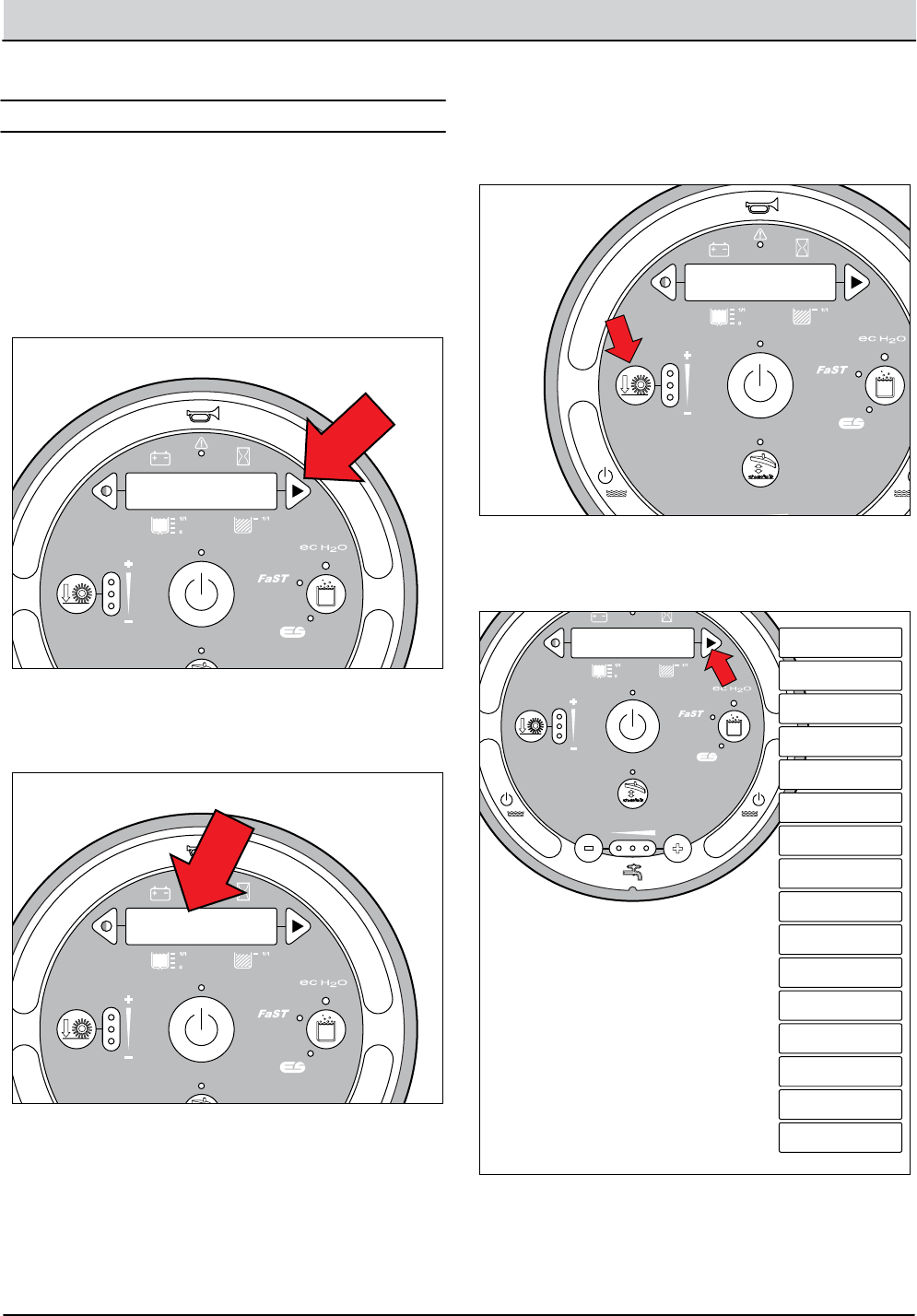
4-4 T16 Service Information 9008149 (1-11)
TROUBLESHOOTING
Tennant Quantum
UI ver X.X
STP001
1. Key switch O. Press and hold the conguration
mode button.
2. Key switch On. Release the conguration mode
button when “CONFIG MODE” appears on the LCD.
CONFIG MODE
STP002
Conguration Mode is an onboard diagnostic utility that
congures controller software to operate optional equip-
ment and to electronically adjust certain output func-
tions.
CMP001
C1:Disk/Cyl
3. Press and release the brush pressure button to enter
Conguration Mode. “C1:Disk/Cyl” will appear on the
LCD.
CMP002
C1:Disk/Cyl
C2:FaST/Es/Ec/No
C3:Set Det Level
C4:Reset Press.?
C5:Main Press #1
XX Amps
C5:Main Press #1
XX Amps
C6:Main Press #2
XX Amps
C7:Main Press #3
XX Amps
C8:Transport Spd
XX.X MPH
C9:Scrubbing Spd
XX.X MPH
C10:Propel H.M.
XXXX.X Hrs
C11:Main Water
Low/Med/High
C12:Side Brush?
Sweep/Scrub
C13:Scrub H.M.
XXXX.X Hr
C14:Reset
C15:Battery Type
C16:Dwn Pres Tst
4. Press and release the conguration mode button to
scroll through a list of utilities as shown below.
CONFIGURATION MODE
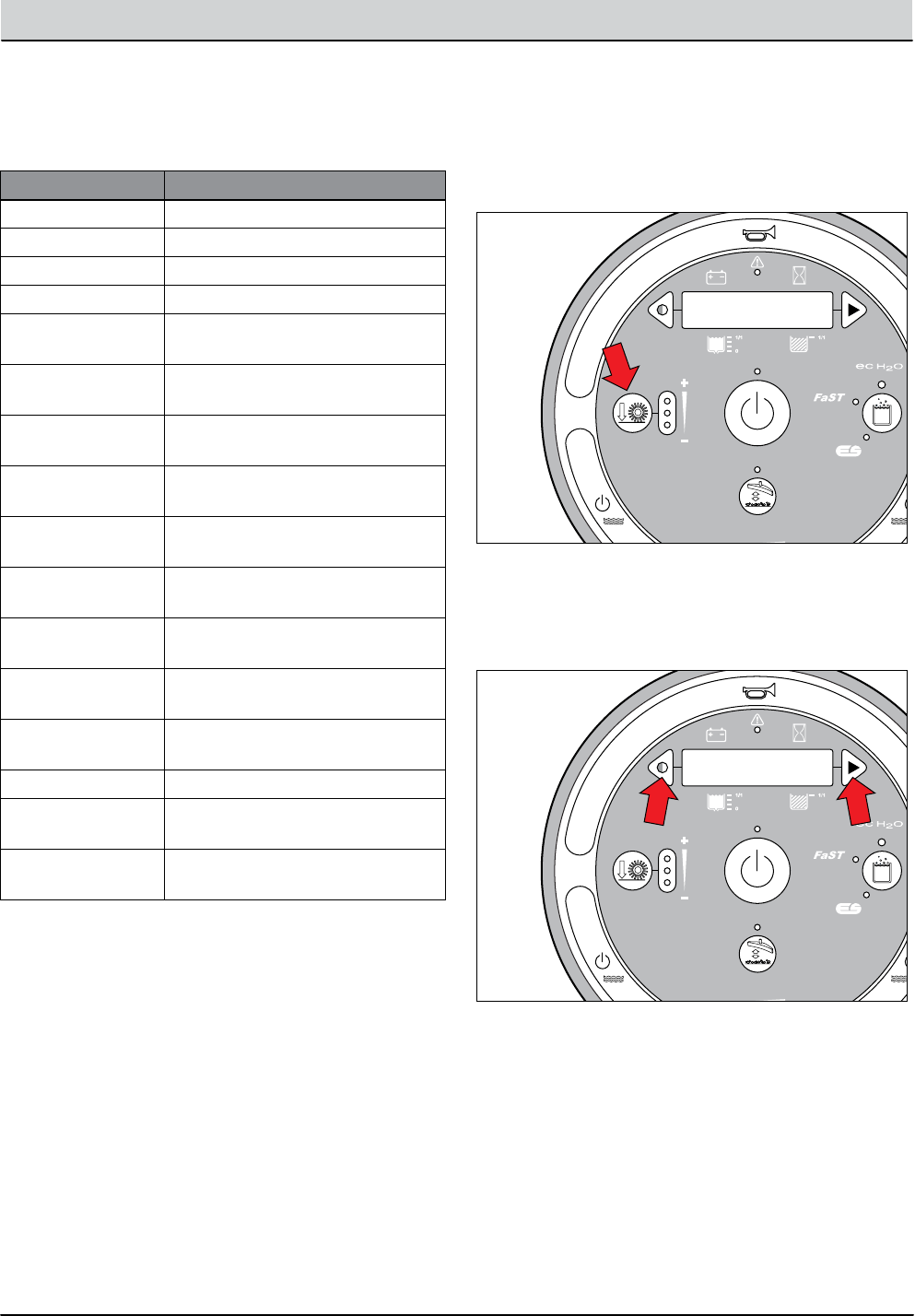
T16 Service Information 9008149 (1-11) 4-5
TROUBLESHOOTING
5. Use the table below for further description of each
Conguration Mode utility.
LCD TEXT DESCRIPTION
C1:Disk/Cyl Congure scrub head type
C2:FaST/Es/Ec/No Congure FaST/ES/ec-H2O
C3:Set Det Level Congure detergent level
C4:Reset Press.? Restore down pressure settings
C5:Main Press #1 Set max down pressure #1
(11 Amps-Fixed)
C6:Main Press #2 Set max down pressure #2
(11-16 Amps, Default 16 Amps)
C7:Main Press #3 Set max down pressure #3
(11-22 Amps, Default 22 Amps)
C8:Transport Spd
XX.X MPH
Adjust maximum forward trans-
port mode speed
C9:Scrubbing Spd
XX.X MPH
Adjust maximum forward scrub
mode speed
C10:Propel H.M.
XXXX.X Hrs
Display/edit propel hour meter.
Password protected
C11:Main Water Select water ow range: (Low,
Medium, High)
C12:Side Brush? Congure side brush option
(sweep or scrub)
C13:Scrub H.M.
XXXX.X Hr
Display/edit scrub hour meter.
Password protected
C14:Reset Restore factory default values.
C15:Battery Type Congure battery type for acid or
gel
C16:Dwn Pres Tst Congure Down Pressure Test
(Disable/Enable)
CMP003
C5:Main Press #1
<XX Amps
6. Press and release the brush pressure button to enable
the change. A “<” symbol will appear on the bottom
line of the LCD indicating the conguration utility is
now enabled.
CMP004
C5:Main Press #1
<XX Amps
7. Press and release the contrast or conguration
mode buttons to change settings. Turn key O
to save selection.
NOTE: C16 Dwn Pres Tst (Down Pressure Test) pertains to
checking cylindrical scrub brush and Pre-Sweep main broom
patterns. See CHECKING CYLINDRICAL SCRUB BRUSH PAT-
TERN in the MAINTENANCE section of this manual.
NOTE: C5, C6, and C7 Main Press (Main Brush Pressure) ad-
justments set the maximum brush motor amp draw for each
down pressure setting; 1 LED, 2 LEDs, or 3 LEDs. C5 (#1) down
pressure is not adjustable.
NOTE: C4:Reset Press.? mode. Press the brush pressure button
after “No” changes to “Yes” following step 7. This completes
the reset process.

4-6 T16 Service Information 9008149 (1-11)
TROUBLESHOOTING
LCD Warnings
WARNING
MESSAGE
WARNING
CODE WARNING DESCRIPTION SET/CLEAR
T16 LCD Warning Messages
W1 W1:Batt Low Low Battery
W2 W2:Sqge Stall SET: Rear squeegee actuator stall condition.
CLEAR: Correct warning condition.
Rear Squeegee Actuator Stalled
W3 W3:Side Stall SET: Side brush actuator stall condition.
CLEAR: Correct warning condition.
Side Brush Actuator Stalled
W4 W4:Unavailable SET: Operator selects a solution technology that
is not congured on the machine.
CLEAR: Release button.
No Optional Solution Enabled
W5 W5:No Side Brush SET: Operator selects the side brush when the
side brush is not enabled in conguration mode.
CLEAR: Release button.
No Side Brush Enabled
W7 W7:Not Active SET: Operator selects a button and the related
function is inactive.
CLEAR: Correct warning condition.
Inactive Button
W8 W8:No Vac Amps SET: Controller senses no current to the vacuum
fan circuit when the output is turned ON.
CLEAR: Correct open circuit condition.
Vacuum Fan Motor, No Current
W9 W9:Open R/R Brush SET: Controller senses no current to the
Right (Disk) or Rear (Cyl) motor circuit when the
output is turned ON.
CLEAR: Correct open circuit condition.
SET: Controller senses no current to the
Left (Disk) or Front (Cyl) motor circuit when the
output is turned ON.
CLEAR: Correct open circuit condition.
SET: Controller senses no current to the side
brush motor circuit when the output is turned ON.
CLEAR: Correct open circuit condition.
Open Right/Rear Brush Motor
W10 W10:Open L/F Brush Open Left/Front Brush Motor
W11 W11:Open SD Brush Open Side Brush Motor
W12 W12:Solution O SET: Solution is OFF during scrub mode for 15
seconds.
CLEAR: Correct warning condition.
Solution Water is O
WMM001
SET: Battery discharge threshold of 30-32 Volts
at KSI terminal or 32-33 Volts at batteries.
CLEAR: Charge batteries to BDI reset threshold
of 37 Volts at KSI terminal or 38 Volts at batteries

T16 Service Information 9008149 (1-11) 4-7
TROUBLESHOOTING
LCD Faults
FAULT
CODE FAULT MESSAGE FAULT DESCRIPTION SET/CLEAR
T16 LCD Fault Messages
F1
F2
F3
F4
F5
F6
F6
F2:SolTank Empty
F3:Vac#Flt#
F4:Batt Very Low
F5:Propel Error
F6:Left Br Flt#
F6:Frnt Br Flt#
F1:Rcv Tank Full
Solution Tank Empty
Over Current Vacuum Fan # (1 or 2) Motors,
Fault Type (1, 2, 3).
SET: Fault #1 = Over Current for 15 Seconds;
Fault #2 = Current Exceeds 25A for 30 Seconds;
Fault #3 = Current Exceeds 35A for 2 Seconds.
CLEAR: Cycle key switch.
SET: Fault #1 = Current Exceeds 30A for 30 Seconds;
Fault #2 = Current Exceeds 40A for 5 Seconds;
Fault #3 = Over Current for 10 Seconds.
CLEAR: Cycle key switch.
SET: Fault #1 = Current Exceeds 30A for 30 Seconds;
Fault #2 = Current Exceeds 40A for 5 Seconds;
Fault #3 = Over Current for 10 Seconds.
CLEAR: Cycle key switch.
SET: Solution tank empty for 60 seconds
CLEAR: Cycle key switch.
SET: Battery discharge threshold of 30.2 Volts
at KSI terminal of PMC or 31.6 Volts at battery.
CLEAR: Charge batteries to BDI reset threshold
of 37 Volts at KSI terminal of PMC or 38.3 Volts
at batteries.
SET: Curtis 1234 PMC to T16 logic board
CAN-bus connectivity problem or
Curtis 1234 PMC power supply problem.
CLEAR: See “Curtis 1234 Controller Diagnostics.”
SET: Recovery tank full for 5 seconds.
CLEAR: Recovery tank not full for 5 seconds.
Very Low Battery Voltage
Propel Controller CAN-bus Connectivity
Error
Left Brush Over Current, Fault #
Front Brush Over Current, Fault #
Recovery Tank Full
FMM001

4-8 T16 Service Information 9008149 (1-11)
TROUBLESHOOTING
FAULT
CODE FAULT MESSAGE FAULT DESCRIPTION SET/CLEAR
T16 LCD Fault Messages, continued
F7
F7
F8
F11
F12
F13
F7:Right Br Flt#
F7:Rear Br Flt#
F8:Hi B3 Current
F11:Act Timeout
F12:Check Brushes
F13:Brush Motor Flt
Right Brush Over Current, Fault #
Rear Brush Over Current, Fault #
Over Current for Side Brush Motor
Main Head Actuator Timed Out Fault.
Check Main Brushes Error Fault (Down Shift)
Brush Motor Fault
FMM002
SET: Fault #1 = Current Exceeds 30A for 30 Seconds;
Fault #2 = Current Exceeds 40A for 5 Seconds;
Fault #3 = Over Current for 10 Seconds.
CLEAR: Cycle key switch.
SET: Fault #1 = Current Exceeds 30A for 30 Seconds;
Fault #2 = Current Exceeds 40A for 5 Seconds;
Fault #3 = Over Current for 10 Seconds.
CLEAR: Cycle key switch.
SET: Fault #1 = Current Exceeds 30A for 30 Seconds;
Fault #2 = Current Exceeds 40A for 5 Seconds;
Fault #3 = Over Current for 10 Seconds.
CLEAR: Cycle key switch.
SET: No actuator stall current sensed after 60
seconds (lift cycle only).
CLEAR: Correct fault condition and cycle
key switch or 1-STEP scrub.
SET: Head lift actuator stalled while trying to
reduce down pressure.
CLEAR: Cycle key switch or 1-STEP scrub.
SET: Controller failed to achieve minimum target
brush motor current after down shifting to the
lowest down pressure setting.
CLEAR: Correct fault condition and cycle
key switch.
LCD Faults, continued

T16 Service Information 9008149 (1-11) 4-9
TROUBLESHOOTING
Tennant Quantum
UI ver X.X
STP001
1. Key switch O. Press and hold the conguration
mode button.
2. Key switch On. Release the conguration mode
button when “CONFIG MODE” appears on the LCD.
CONFIG MODE
STP002
PROPEL DIAG MODE
PDM001
CONFIG MODE
SELF TEST
MANUAL MODE
INPUT DISPLAY
PROPEL DIAG MODE
3. Press and release the conguration mode button to
scroll through a list of utilities until “PROPEL DIAG
MODE” appears on the LCD.
P1: Curtis Online/
Error
PDM002
4. Press and release the brush pressure button to
enter Propel Diagnostic Mode. “P1:Curtis Online...” will
appear on the LCD.
Propel Diagnostic Mode (Propel Input Mode) is an on-
board diagnostic utility that displays Curtis 1234 control-
ler inputs on the instrument panel LCD (Liquid Crystal
Display). The input data is transmitted to the T16 control-
ler through a CAN-bus (Controller Area Network).
PROPEL DIAGNOSTIC MODE

4-10 T16 Service Information 9008149 (1-11)
TROUBLESHOOTING
P1: Curtis Online/
Error P1:Curtis Online/
Error
P2:Throttle
XXXX.X V
P3:Brake Pedal
On/Off
P4:Direction Fwd/
Rev
P5:Speed
XXXX.X Mph
P6:Curtis Temp
XXXX.XC XXXX.XF
P7:Motor Temp
XXXX.XC XXXX.XF
P8:PropelCurrent
XXXX.X A
PDM003
5. Press and release the conguration mode button
to scroll through a list of Curtis 1234 controller inputs.
6. The table below describes how each input operates.
PDM004
10
11
T16 Propel Diagnostic Mode
Curtis/T16 controllers CAN-bus
connection status
P1:Curtis Online/
Error
P1
Displays foot throttle commanded
voltage (0-5V).
P2:Throttle
XXXX.X v
P2
Displays brake pedal command
(On/O).
P3:Brake Pedal
On/O
P3
Displays directional switch input
(Fwd/Rev).
P4:Direction Fwd/
Rev
P4
Displays propel speed from motor
encoder located in drive assembly.
P5:Speed
XXXX.X Mph
P5
Displays Curtis 1234 controller
temperature
P6:Curtis Temp
XXXX.XC XXXX.XF
P6
Displays drive motor temperature.
Thermistor located in drive assembly.
P7:Motor Temp
XXXX.XC XXXX.XF
P7
Displays propel motor current.P8:PropelCurrent
XXXX.X A
P8
LCD MESSAGECODE DESCRIPTION

T16 Service Information 9008149 (1-11) 4-11
TROUBLESHOOTING
Curtis 1234 Controller Diagnostic LED Operation
ENC
PHASE B
1
2
3
4567
8
9
10
1112
242526272829303132333435
13141516171819202122
23
KSI
PROP
DRIVER
DRIVER 4
DRIVER
3
DRIVER
7
DRIVER 2
DRIVER 1
I/O GND
SW2/ANA2
SW3
SW4
SW5
SW6
SW16
THR
WIPER
POT
LOW
SW7
SW1/ANA1
COIL
RETURN
+12V
+5V
THR POT
HI
BRK
POT HI
TX
BRK
WIPER
RX
ANA
OUT
DRIVER 6
ENC
PHASE
A
CAN
TERM H
SW8
CAN H
CAN L
CAN
TERM L
Status LEDs
1
12
24
35
13
23
PMC002
Display
Neither LED illuminated Controller is not powered on, has a dead battery,
or is severely damaged.
Yellow LED ashing Controller is operating normally.
Yellow and red LEDs both on solid Controller is in Flash program mode.
Red LED on solid Watchdog failure. Cycle KSI to restart.
Red LED and yellow LED ashing
alternately
*The red LED ashes once to indicate that the rst digit of the code will follow; the yellow LED then ashes the
appropriate number of times for the rst digit. The red LED ashes twice to indicate that the second digit of the code
will follow; the yellow LED ashes the appropriate number of times for the second digit.
Controller has detected a fault. 2-digit code*
ashed by yellow LED identies the specic fault;
one or two ashes by red LED indicate whether
rst or second code digit will follow.
Status
Types of LED Display
Example: Battery Undervoltage (Code 23)
RED REDYELLOW YELLOW
(rst digit) (second digit)(2) (3)

4-12 T16 Service Information 9008149 (1-11)
TROUBLESHOOTING
Curtis 1234 Controller Diagnostic Codes, continued
13
14
15
16
17 Severe Undervoltage
Reduced drive torque.
TROUBLESHOOTING CHART
FAULT CONDITION
CODE EFFECT OF FAULT POSSIBLE CAUSE SET/CLEAR CONDITIONS
12 Controller Overcurrent
ShutdownMotor;
ShutdownMainContactor;
ShutdownEMBrake;
ShutdownThrottle;
FullBrake;
ShutdownPump.
1. Leakage to vehicle frame from phase
U, V, or W (short in motor stator).
2. Controller defective.
Current Sensor Fault
ShutdownMotor;
ShutdownMainContactor;
ShutdownEMBrake;
ShutdownThrottle;
FullBrake;
ShutdownPump.
1. External load on capacitor bank (B+
connection terminal) that prevents
the capacitor bank from charging.
2. See Monitor menu » Battery:
Capacitor Voltage.
Precharge Failed
ShutdownMotor;
ShutdownMainContactor;
ShutdownEMBrake;
ShutdownThrottle;
FullBrake;
ShutdownPump.
1. See Monitor menu » Controller:
Temperature.
2. Controller is operating in an extreme
environment.
Controller Severe Undertemp
ShutdownMotor;
ShutdownMainContactor;
ShutdownEMBrake;
ShutdownThrottle;
FullBrake;
ShutdownPump.
1. See Monitor menu » Controller:
Temperature.
2. Controller is operating in an extreme
environment.
3. Excessive load on vehicle.
4. Improper mounting of controller.
Controller Severe Overtemp
ShutdownMotor;
ShutdownMainContactor;
ShutdownEMBrake;
ShutdownThrottle;
FullBrake;
ShutdownPump.
1. Battery Menu parameters are
misadjusted.
2. Non-controller system drain on
battery.
3. Battery resistance too high.
4. Battery disconnected while driving.
5. See Monitor menu » Battery:
Capacitor Voltage.
6. Blown B+ fuse or main contactor
did not close.
Set: Controller current sensors have
invalid oset reading.
Clear: Cycle KSI.
Set: Phase current exceeded the
current measurement limit.
Clear: Cycle KSI.
Set: Precharge failed to charge the
capacitor bank to the KSI voltage.
Clear: Cycle interlock input or use VCL
function.
Set: Heatsink temperature below -40˚C.
Clear: Bring heatsink temperature
above -40˚C, and cycle interlock or KSI.
Set: Heatsink temperature above +95˚C.
Clear: Bring heatsink temperature
below +95˚C, and cycle interlock or KSI.
Set: Capacitor bank voltage dropped
below the severe undervoltage limit
with FET bridge enabled.
Clear: Bring capacitor voltage above
severe undervoltage limit.
1. External short of phase U, V, or W
motor connections.
2. Motor parameters are mis-tuned.
3. Controller defective.
PMC003

T16 Service Information 9008149 (1-11) 4-13
TROUBLESHOOTING
Curtis 1234 Controller Diagnostic Codes, continued
TROUBLESHOOTING CHART, continued
FAULT CONDITION
CODE EFFECT OF FAULT POSSIBLE CAUSE SET/CLEAR CONDITIONS
18 Severe Overvoltage 1. See Monitor menu»Battery: Set: Capacitor bank voltage exceeded
the Severe Overvoltage limit with FET
bridge enabled.
Clear: Bring capacitor voltage below
Severe Overvoltage limit, and then
cycle KSI.
ShutdownMotor; Capacitor Voltage.
ShutdownMainContactor; 2. Battery menu parameters are
ShutdownEMBrake; misadjusted.
ShutdownThrottle; 3. Battery resistance too high for given
FullBrake; regen current.
ShutdownPump. 4. Battery disconnected while regen braking.
22 Controller Overtemp Cutback 1. See Monitor menu»Controller: Set: Heatsink temperature exceeded
85˚C.
Clear: Bring heatsink temperature
below 85˚C.
Reduced drive and brake Temperature.
torque. 2. Controller is performance-limited
at this temperature.
3. Controller is operating in an extreme
environment.
4. Excessive load on vehicle.
5. Improper mounting of controller.
23 Undervoltage Cutback 1. Normal operation. Fault shows that Set: Capacitor bank voltage dropped
below the Undervoltage limit with the
FET bridge enabled.
Clear: Bring capacitor voltage above
the Undervoltage limit.
Reduced drive torque. the batteries need recharging.
Controller is performance limited
at this voltage.
2. Battery parameters are misadjusted.
3. Non-controller system drain on battery.
4. Battery resistance too high.
5. Battery disconnected while driving.
6. See Monitor menu»Battery:
Capacitor Voltage.
7. Blown B+ fuse or main contactor
did not close.
24 Overvoltage Cutback 1. Normal operation. Fault shows that Set: Capacitor bank voltage exceeded
the Overvoltage limit with the FET
bridge enabled.
Clear: Bring capacitor voltage below
the Overvoltage limit.
Reduced brake torque. regen braking currents elevated the
battery voltage during regen braking.
Controller is performance limited
at this voltage.
2. Battery parameters are misadjusted.
3. Battery resistance too high for given
regen current.
4. Battery disconnected while regen braking.
5. See Monitor menu»Battery:
Capacitor Voltage.
25 +5V Supply Failure 1. External load impedance on the Set: +5V supply (pin 26) outside the
+5V +/-10% range.
Clear: Bring voltage within range.
None, unless a fault action +5V supply (pin 26) is too low.
is programmed in VCL. 2. See Monitor menu»outputs:
5 Volts and Ext Supply Current.
26 Digital Out 6 Overcurrent 1. External load impedance on Digital Set: Digital Output 6 (pin 19) current
exceeded 15 mA.
Clear: Remedy the overcurrent cause
and use the VCL function Set_DigOut()
to turn the driver on again.
Digital Output 6 driver Output 6 driver (pin 19) is too low.
will not turn on.
PMC004

4-14 T16 Service Information 9008149 (1-11)
TROUBLESHOOTING
Curtis 1234 Controller Diagnostic Codes, continued
TROUBLESHOOTING CHART, continued
FAULT CONDITION
CODE EFFECT OF FAULT POSSIBLE CAUSE SET/CLEAR CONDITIONS
27 Digital Out 7 Overcurrent 1. External load impedance on Digital Set: Digital Output 7 (pin 20) current
exceeded 15 mA.
Clear: Remedy the overcurrent cause
and use the VCL function Set_DigOut()
to turn the driver on again.
Digital Output 7 driver Output 7 driver (pin 20) is too low.
will not turn on.
28 Motor Temp Hot Cutback 1. Motor temperature is at or above Set: Motor temperature is at or above
the Temperature Hot parameter
setting.
Clear: Bring the motor temperature
within range.
Reduced drive torque. the programmed Temperature Hot
setting, and the requested current
is being cut back.
2. Motor Temperature Control Menu
parameters are mis-tuned.
3. See Monitor menu»Motor:
Temperature and »Inputs: Analog2.
4. If the application doesn’t use a mo-
tor thermistor, Temp Compensation
and Temp Cutback should be
programmed O.
29 Motor Temp Sensor Fault 1. Motor thermistor is not connected Set: Motor thermistor input (pin 8) is at
the voltage rail (0 or 10V).
Clear: Bring the motor thermistor input
voltage within range.
MaxSpeed reduced (LOS, properly.
Limited Operating Strategy), 2. If the application does not use a
and motor temperature thermistor, Temp Compensation
cutback disabled. and Temp Cutback should be
programmed O.
3. See Monitor menu»Motor:
Temperature and »Inputs: Analog2.
31 Coil1 Driver Open/Short 1. Open or short on driver load. Set: Driver 1 (pin 60) is either open or
shorted.
Clear: Correct open or short, and cycle driver.
ShutdownDriver1. 2. Dirty connector pins.
3. Bad crimps or faulty wiring.
31 Main Open/Short 1. Open or short on driver load. Set: Main contactor driver (pin 6) is
either open or shorted.
Clear: Correct open or short, and cycle
driver.
ShutdownMotor; 2. Dirty connector pins.
ShutdownMainContactor; 3. Bad crimps or faulty wiring.
ShutdownEMBrake;
ShutdownThrottle;
FullBrake;
ShutdownPump.
32 Coil2 Driver Open/Short 1. Open or short on driver load. Set: Driver 2 (pin 5) is either open or
shorted.
Clear: Correct open or short, and cycle driver.
ShutdownDriver2. 2. Dirty connector pins.
3. Bad crimps or faulty wiring.
32 EMBrake Open/Short 1. Open or short on driver load. Set: Electromagnetic brake driver (pin 5)
is either open or shorted.
Clear: Correct open or short, and cycle
driver.
ShutdownEMBrake; 2. Dirty connector pins.
ShutdownThrottle; 3. Bad crimps or faulty wiring.
FullBrake.
33 Coil3 Driver Open/Short 1. Open or short on driver load. Set: Driver 3 (pin 4) is either open or
shorted.
Clear: Correct open or short, and cycle driver.
ShutdownDriver3. 2. Dirty connector pins.
3. Bad crimps or faulty wiring.
34 Coil4 Driver Open/Short 1. Open or short on driver load. Set: Driver 4 (pin3) is either open or
shorted.
Clear: Correct open or short, and cycle driver.
ShutdownDriver4. 2. Dirty connector pins.
3. Bad crimps or faulty wiring.
PMC005

T16 Service Information 9008149 (1-11) 4-15
TROUBLESHOOTING
Curtis 1234 Controller Diagnostic Codes, continued
TROUBLESHOOTING CHART, continued
FAULT CONDITION
CODE EFFECT OF FAULT POSSIBLE CAUSE SET/CLEAR CONDITIONS
35 PD Open/Short 1. Open or short on driver load. Set: Proportional driver (pin 2) is either
open or shorted.
Clear: Correct open or short, and cycle driver.
ShutdownPD. 2. Dirty connector pins.
3. Bad crimps or faulty wiring.
36 Encoder Fault 1. Motor encoder failure. Set: Motor encoder phase failure
detected.
Clear: Cycle KSI.
ShutdownEMBrake. 2. Bad crimps or faulty wiring.
3. See Monitor menu»Motor:
Motor RPM.
37 Motor Open 1. Motor phase is open. Set: Motor phase U, V, or W detected
open.
Clear: Cycle KSI.
ShutdownMotor; 2. Bad crimps or faulty wiring.
ShutdownMainContactor;
ShutdownEMBrake;
ShutdownThrottle;
FullBrake;
ShutdownPump.
38 Main Contactor Welded 1. Main contactor tips are welded Set: Just prior to the main contactor
closing, the capacitor bank voltage (B+
connection terminal) was loaded for a
short time and the voltage did not
discharge.
Clear: Cycle KSI
ShutdownMotor; closed.
ShutdownMainContactor; 2. Motor phase U or V is disconnected
ShutdownEMBrake; or open.
ShutdownThrottle; 3. An alternate voltage path (such as an
FullBrake; external precharge resistor) is
ShutdownPump. providing a current to the capacitor
bank (B+ connection terminal).
39 Main Contactor Did Not Close 1. Main contactor did not close. Set: With the main contactor
commanded closed, the capacitor
bank voltage (B+ connection terminal)
did not charge to B+.
Clear: Cycle KSI.
ShutdownMotor; 2. Main contactor tips are oxidized,
ShutdownMainContactor; burned, or not making good contact.
ShutdownEMBrake; 3. External load on capacitor bank
ShutdownThrottle; (B+ connection terminal) that pre-
FullBrake; vents capacitor bank from charging.
ShutdownPump. 4. Blown B+ fuse.
41 Throttle Wiper High 1. See Monitor menu »Inputs: Set: Throttle pot wiper (pin 16) voltage
is higher than the high fault threshold
(can be changed with the VCL function
Setup_Pot_Faults())
Clear: Bring throttle pot wiper voltage
below the fault threshold.
ShutdownThrottle. Throttle Pot.
2. Throttle pot wiper voltage too high.
42 Throttle Wiper Low 1. SeeMonitor menu »Inputs: Set: Throttle pot wiper (pin 16) voltage
is lower than the low fault threshold
(can be changed with the VCL function
Setup_Pot_Faults()).
Clear: Bring throttle pot wiper voltage
above the fault threshold.
ShutdownThrottle. Throttle Pot.
2. Throttle pot wiper voltage too low.
43 Pot2 Wiper High 1. SeeMonitor menu »Inputs: Set: Pot2 wiper (pin 17) voltage is
higher than the high fault threshold
(can be changed with the VCL function
Setup_Pot_Faults()).
Clear: Bring Pot2 wiper voltage below
the fault threshold.
FullBrake. Pot2 Raw.
2. Pot2 wiper voltage too high.
PMC006

4-16 T16 Service Information 9008149 (1-11)
TROUBLESHOOTING
Curtis 1234 Controller Diagnostic Codes, continued
TROUBLESHOOTING CHART, continued
FAULT CONDITION
CODE EFFECT OF FAULT POSSIBLE CAUSE SET/CLEAR CONDITIONS
44 Pot2 Wiper Low 1. SeeMonitor menu» Inputs: Set: Pot2 wiper (pin 17) voltage
is lower than the low fault threshold
(can be changed with the VCL function
Setup_Pot_Faults() ).
Clear: Bring Pot2 wiper voltage
above the fault threshold.
FullBrake. Pot2 Raw.
2. Pot2 wiper voltage too low.
45 Pot Low Overcurrent 1. See Monitor menu »Outputs: Set: Pot low (pin 18) current exceeds
10 mA.
Clear: Clear pot low overcurrent
condition and cycle KSI.
ShutdownThrottle; Pot Low.
FullBrake. 2. Combined pot resistance connected
to pot low is too low.
46 EEPROM Failure 1. Failure to write to EEPROM Set: Controller operating system tried
to write to EEPROM memory and failed.
Clear: Download the correct software
(OS) and matching parameter default
settings into the controller and cycle
KSI.
memory. This can be caused by
EEPROM memory writes initiated
by VCL, by the CAN bus, by
adjusting parameters with the
programmer, or by loading new
software into the controller.
47 HPD/Sequencing Fault 1. KSI, interlock, direction, and throttle Set: HPD (High Pedal Disable) or
sequencing fault caused by incorrect
sequence of KSI, interlock, direction
and throttle inputs.
Clear: Reapply inputs in correct sequence.
ShutdownThrottle. inputs applied in incorrect sequence.
2. Faulty wiring, crimps, or switches at
KSI, interlock, direction, or throttle
inputs.
3. See Monitor menu »Inputs.
47 Emer Rev HPD 1. Emergency Reverse operation has Set: At the conclusion of Emergency
Reverse, the fault was set becase various
inputs were not returned to neutral.
Clear: If EMR_Interlock = On, clear the
interlock, throttle, and direction inputs.
If EMR_Interlock = O, clear the
throttle and direction inputs.
ShutdownThrottle; concluded, but the throttle, forward
ShutdownEMBrake. and reverse inputs, and interlock
have not been returned to neutral.
49 Parameter Change Fault 1. This is a safety fault caused by a Set: Adjustment of a parameter setting
that requires cycling of KSI.
Clear: Cycle KSI
ShutdownMotor; change in certain parameter
ShutdownMainContactor; settings so that the vehicle will not
ShutdownEMBrake; operate until KSI is cycled.
ShutdownThrottle; For example, if a user changes the
FullBrake; Throttle Type this fault will appear
ShutdownPump. and require cycling KSI before the
vehicle can operate.
ShutdownMotor;
ShutdownMainContactor;
ShutdownEMBrake;
ShutdownThrottle;
ShutdownInterlock;
ShutdownDriver1;
ShutdownDriver2;
ShutdownDriver3;
ShutdownDriver4;
ShutdownPD;
FullBrake;
ShutdownPump.
PMC007

T16 Service Information 9008149 (1-11) 4-17
TROUBLESHOOTING
Curtis 1234 Controller Diagnostic Codes, continued
TROUBLESHOOTING CHART, continued
FAULT CONDITION
CODE EFFECT OF FAULT POSSIBLE CAUSE SET/CLEAR CONDITIONS
68 VCL Run Time Error 1. VCL code encountered a runtime Set: Runtime VCL code error condition.
Clear: Edit VCL application software to
x this error condition; ash the new
compiled software and matching
parameter defaults; cycle KSI.
VCL error.
2. See Monitor menu » Controller:
VCL Error Module and VCL Error.
This error can then be compared to
the runtime VCL module ID and
error code denitions found in the
specic OS system information le.
69 External Supply Out of Range 1. External load on the 5V and 12V Set: The external supply current (com-
bined current used by the 5V supply
[pin 26] and 12V supply [pin 25]) is either
greater than the lower current threshold.
The two thresholds are dened by the
External Supply Max and External Supply
Min parameter settings.
Clear: Bring the external supply current
within range.
None, unless a fault action supplies draws either too much or
is programmed in VCL. too little current.
2. Fault Checking Menu parameters
Ext Supply Max and Ext Supply Min
are mis-tuned.
3. See Monitor menu » Outputs:
Ext Supply Current.
71 OS General 1. Internal controller fault. Set: Internal controller fault detected.
Clear: Cycle KSI
72 PDO Timeout 1. Time between CAN PDO messages Set: Time between CAN PDO messages
received exceeded the PDO Timeout
Period.
Clear: Cycle KSI.
ShutdownInterlock; received exceeded the PDO
CAN NMT State set Timeout Period.
to Pre-operational.
73 Stall Detected 1. Stalled motor. Set: No motor encoder movement
detected.
Clear: Either cycle KSI, or
detect valid motor encoder signals
while operating in LOS mode and
return Throttle Command = 0 and
Motor RPM= 0
ShutdownEMBrake. 2. Motor encoder failure.
3. Bad crimps or faulty wiring.
4. Problems with power supply for
the motor encoder.
5. See Monitor menu » Motor:
Motor RPM.
ShutdownMotor;
ShutdownMainContactor;
ShutdownEMBrake;
ShutdownThrottle;
ShutdownInterlock;
ShutdownDriver1;
ShutdownDriver2;
ShutdownDriver3;
ShutdownDriver4;
ShutdownPD;
FullBrake;
ShutdownPump.
ShutdownMotor;
ShutdownMainContactor;
ShutdownEMBrake;
ShutdownThrottle;
ShutdownInterlock;
ShutdownDriver1;
ShutdownDriver2;
ShutdownDriver3;
ShutdownDriver4;
ShutdownPD;
FullBrake;
ShutdownPump.
PMC008

4-18 T16 Service Information 9008149 (1-11)
TROUBLESHOOTING
Curtis 1234 Controller Diagnostic Codes, continued
87 Motor Characterization Fault 1. Motor characterization failed during Set: Motor characterization failed during
the motor characterization process.
Clear: Correct fault; cycle KSI.
ShutdownMotor; characterization process. See Monitor
ShutdownMainContactor; menu » Controller: Motor
ShutdownEMBrake; Characterization Error for cause:
ShutdownThrottle; 0=none
FullBrake; 1=encoder signal seen, but step size
ShutdownPump. not determined; set Encoder Step
Size manually
2=motor temp sensor fault
3=motor temp hot cutback fault
4= controller overtemp cutback fault
5=controller undertemp cutback fault
6=undervoltage cutback fault
7=severe overvoltage fault
8=encoder signal not seen, or one or
both channels missing
9=motor parameters out of character-
ization range.
89 Motor Type Fault 1. The Motor_Type parameter value Set: Motor_Type parameter is set to an
illegal value.
Clear: Set Motor_Type to correct value
and cycle KSI.
ShutdownMotor; is out of range.
ShutdownMainContactor;
ShutdownEMBrake;
ShutdownThrottle;
FullBrake;
ShutdownPump.
91 VCL/OS Mismatch 1. The VCL software in the controller Set: VCL and OS software do not match;
when KSI cycles, a check is made to
verify that they match and a fault is
issued when they do not.
Clear: Download the correct VCL and
OS software into the controller.
does not match the OS software in
the controller.
92 EM Brake Failed to Set 1. Vehicle movement sensed after the Set: After the EM Brake was commanded
to set and time has elapsed to allow the
brake to fully engage, vehicle movement
has been sensed.
Clear: Activate the throttle.
ShutdownEMBrake; EM Brake has been commanded
ShutdownThrottle. to set.
2. EM Brake will not hold the motor
from rotating.
93 Encoder LOS (Limited 1. Limited Operating Strategy (LOS) Set: Encoder Fault (Code 36) or Stall
Detect Fault (Code 73) was activated,
and Brake or Interlock has been applied
to activate LOS control mode, allowing
limited motor control.
Clear: Cycle KSI, or if LOS mode was acti-
vated by the Stall Fault, clear by ensuring
encoder senses proper operation, Motor
RPM = 0, and Throttle Command = 0.
Operating Strategy) control mode has been activated, as
Enter LOS control mode. a result of either an Encoder Fault
(Code 36) or a Stall Detect Fault
(Code 73).
2. Motor encoder failure.
3. Bad crimps or faulty wiring.
4. Vehicle is stalled.
TROUBLESHOOTING CHART, continued
FAULT CONDITION
CODE EFFECT OF FAULT POSSIBLE CAUSE SET/CLEAR CONDITIONS
ShutdownMotor;
ShutdownMainContactor;
ShutdownEMBrake;
ShutdownThrottle;
ShutdownInterlock;
ShutdownDriver1;
ShutdownDriver2;
ShutdownDriver3;
ShutdownDriver4;
ShutdownPD;
FullBrake;
ShutdownPump.
PMC009

T16 Service Information 9008149 (1-11) 4-19
TROUBLESHOOTING
Curtis 1234 Controller Diagnostic Codes, continued
PMC010
TROUBLESHOOTING CHART, continued
FAULT CONDITION
CODE EFFECT OF FAULT POSSIBLE CAUSE SET/CLEAR CONDITIONS
94 Emer Rev Timeout 1. Emergency Reverse was activated Set: Emergency Reverse was activated
and ran until the EMR Timeout timer
expired.
Clear: Turn the emergency reverse
input O.
ShutdownEMBrake; and concluded because the EMR
ShutdownThrottle. Timeout timer has expired.
2. The emergency reverse input is
stuck On.
98 Illegal Model Number 1. Model_Number variable contains Set: Illegal Model_Number variable; when
KSI cycles a check is made to conrm
a legal Model_Number, and a fault is
issued if one is not found.
Clear: Download appropriate software
for your controller model.
ShutdownMotor; illegal value (not 1234, 1236, 1238,
ShutdownMainContactor; or 1298).
ShutdownEMBrake; 2. Software and hardware do not match.
ShutdownThrottle; 3. Controller defective.
FullBrake;
ShutdownPump.

4-20 T16 Service Information 9008149 (1-11)
TROUBLESHOOTING
Tennant Quantum
UI ver X.X
STP001
1. Key switch O. Press and hold the conguration
mode button.
2. Key switch On. Release the conguration mode
button when “CONFIG MODE” appears on the LCD.
CONFIG MODE
STP002
INPUT DISPLAY
IDM001
CONFIG MODE
SELF TEST
MANUAL MODE
INPUT DISPLAY
PROPEL DIAG MODE
3. Press and release the conguration mode button to
scroll through a list of utilities until “INPUT DISPLAY”
appears on the LCD.
I1:Sol Tank 2(2)
XXXX Filt(Raw)
IDM002
4. Press and release the brush pressure button to enter
Input Display Mode. “I1:Sol Tank, XXXX Filt(Raw)” will
appear on the LCD.
Input Display Mode is an onboard diagnostic utility that
displays controller input conditions. Input Display Mode
displays LCD text messages for hard-wired switch, sensor,
and touch panel button inputs.
INPUT DISPLAY MODE
NOTE: “XXXX Filt(Raw)” refers to encrypted software code
and should be ignored in the “I1” input mode utility. The
numbers “2(2),” as shown below, represent the solution tank
water level from 1 to 5 bars on the LCD. For example, when
lling an empty solution tank, the numbers will increase
gradually from 0(0) to 5(5) in a 0(0), 0(1), 1(1), 1(2), 2(2), 2(3)...
sequence.

T16 Service Information 9008149 (1-11) 4-21
TROUBLESHOOTING
I1:Sol Tank 2(2)
XXXX Filt(Raw)
IDM003
I2:Rcv Full On/Off
I3:ES Float
Open/Closed
I4:Seat Switch:
Not Empty/Empty
I7:Side Br On/Off
I8:PreSw En On/Off
I1:Sol Tank 2(2)
XXXX Filt(Raw)
5. Press and release the conguration mode button to
scroll through a list of hard-wired switch and sensor
inputs.
IX:Input Mode
Message Here
IDM004
I5: Horn Button
Pressed
I6:Vac Button
Pressed
I9:Inc Solution
Button Pressed
I10:Dec Solution
Button Pressed
I11:Left Water Off
Button Pressed
I12:Right Water Off
Button Pressed
I13:One Step
Button Pressed
I14:Down Pres.
Button Pressed I15:Alt Solution
Button Pressed
6. Press any touch panel button to display a
corresponding LCD text message. The message
conrms that the control board received the input.

4-22 T16 Service Information 9008149 (1-11)
TROUBLESHOOTING
Tennant Quantum
UI ver X.X
STP001
1. Key switch O. Press and hold the conguration
mode button.
2. Key switch On. Release the conguration mode
button when “CONFIG MODE” appears on the LCD.
CONFIG MODE
STP002
MANUAL MODE
MMP001
CONFIG MODE
SELF TEST
MANUAL MODE
INPUT DISPLAY
PROPEL DIAG MODE
3. Press and release the conguration mode button to
scroll through a list of utilities until “MANUAL MODE”
appears on the LCD.
Manual Mode On
M1:L Brush XX.X
MMP002
4. Press and release the brush pressure button to
enter Manual Mode. “Manual Mode On...” will appear
on the LCD.
Manual Mode is an onboard diagnostic utility that manu-
ally activates machine functions and displays output cur-
rent in “XX.X Amps” format. This mode bypasses interlock-
ing inputs and should be used for diagnostic purposes
only.
MANUAL MODE
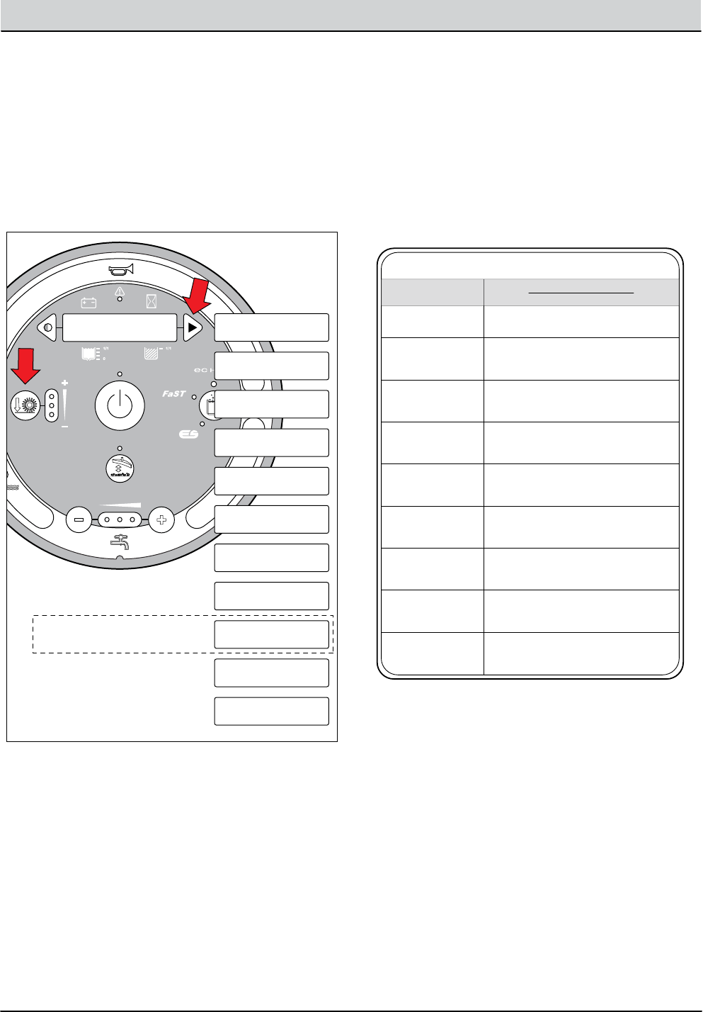
T16 Service Information 9008149 (1-11) 4-23
TROUBLESHOOTING
Manual Mode On
M1:L Brush XX.X
Note: M9: “He” = Main
Scrub Head Lift Actuator
MMP003
Manual Mode On
M1:L Brush XX.X
Manual Mode On
M2:R Brush XX.X
Manual Mode On
M3:S Brush XX.X
Manual Mode On
M4:Vac 1 XX.X
Manual Mode On
M5:Vac 2 XX.X
Manual Mode On
M6:FaST On/Off
Manual Mode On
M7:ES On/Off
Manual Mode On
M8:ec-H2O On/Off
Manual Mode On
M9:He XX.X
Manual Mode On
M10:Sq Act XX.X
Manual Mode On
M11:SB Act XX.X
5. Press and release the conguration mode button
to scroll through a list of output functions. Press the
brush down pressure button to select a specic
output function.
6. Enable specic output functions by using the table
below.
NOTE: Outputs requiring multiple button activation must be
pressed and released in sequence.
MMP004
10
11
T16 Manual Mode Operation
1-STEP Scrub Button On
1-STEP Scrub button toggles On/O
Scrub Brushes
Side brush switch On + Horn button
Horn button toggles On/O
Side Brush
Vacuum Fan/Squeegee Button
Vacuum Fan/Squeegee button toggles On/O
Vacuum Fan(s),
Scrubbing
FaST button On
FaST button toggles On/O
FaST Pump
*If Congured
ES button On
ES button toggles On/O
ES Pump
*If Congured
ecH2O button On
ecH2O button toggles On/O
ecH2O Module
*If Congured
Brush Pressure, Water Flow (-), 1-STEP On
Brush down pressure button disables
Scrub Head
Lift Actuator
Brush Pressure, Water Flow (-), Vac/Sq On
Brush down pressure button disables
Rear Squeegee
Lift Actuator
Brush Pressure, Water Flow (-), Horn Button
Brush down pressure button disables
Side Brush
Lift Actuator
FUNCTION ENABLE
DISABLE
NOTE: Conventional solution control is manually operated
with the scrub brushes. The solution control LEDs will need to
be activated while in scrub brushes - manual mode.
NOTE: The XX.X format indicates that the actual amper-
age value will vary. See the “Specications” section of this
manual for approximate amp draw values .
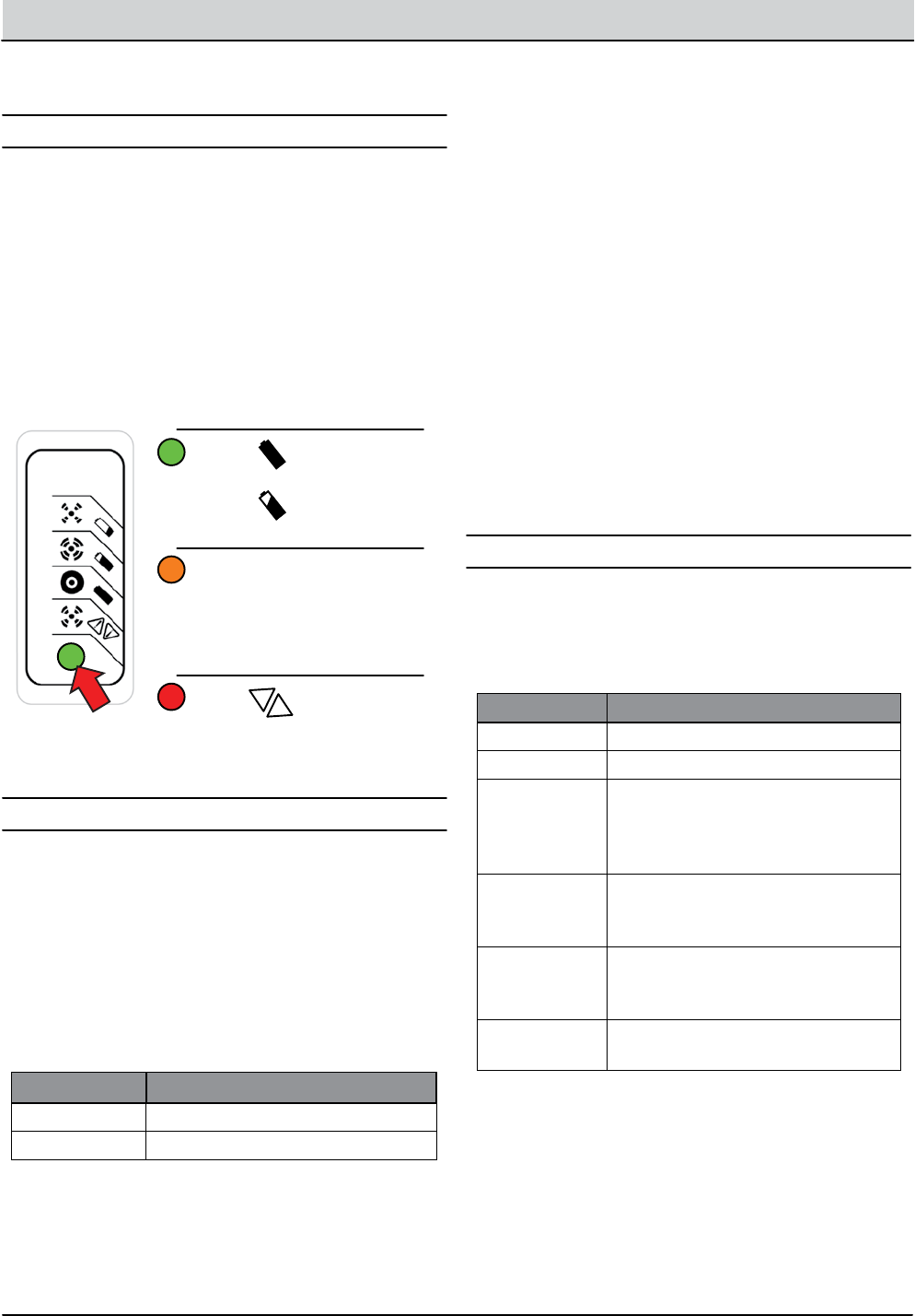
4-24 T16 Service Information 9008149 (1-11)
TROUBLESHOOTING
Battery Charger, Standard
RED FLASHES POSSIBLE CAUSE
1Battery High Voltage
2Battery Low Voltage
3Charge timeout. Batteries failed to
reach required voltage. Charger
output was reduced due to high
temperatures.
4Check battery. Battery could not
be trickle charged up to minimum
voltage.
5Over-Temperature: Charger shut
down due to high internal tempera-
ture.
6Charger internal fault. Disconnect
for 15 seconds and reset charger.
This charger is programmable for standard lead-acid,
heavy duty lead-acid batteries. The setting is displayed
using the blink on/o method each time the battery
charger is connected to an AC power supply and the
charger is disconnected from the batteries.
The standard battery charger utilizes a single-LED
display. The LED ashes green during the charging cycle
and changes to solid green when the charging cycle is
complete.
OPERATION
FAULTS
CONFIGURATION
1. Key O. Disconnect battery charger from AC power
supply and the batteries. Wait 30 seconds before
proceeding to step 2 to allow for capacitor discharge.
ALGORITHM # BATTERY TYPE
3Lead-Acid, 235 Ah
7Lead-Acid, 360 Ah
Green Solid: Charge
Complete
Flashing:
Charging
Amber Flashing:
Reduced Power
Mode. Low AC
Voltage or Hi
Charger Temp
Red Flashing:
Charger Error
See Faults Below
!
!
DQC001
2. Connect charger to AC supply and observe the
LED display. It will blink on/o to indicate the cur-
rent battery charger setting for 11 seconds.
1. Key O. Disconnect battery charger from AC power
supply and the batteries. Wait 30 seconds before
proceeding to step 2 to allow for capacitor discharge.
DISPLAYING CURRENT CHARGER SETTING
CHANGING CHARGER SETTING
2. Connect charger to AC supply and observe the
LED display. It will blink on/o to indicate the cur-
rent battery charger setting for 11 seconds.
3. Connect the battery charger to the batteries for 2
seconds and then disconnect from the batteries,
during the 11 second window, to advance to the
next highest setting.
NOTE: The 11 second window expands to 30 seconds after
the rst change has been made.
4. Wait 45 seconds after a change has been made to
save the new charger setting.
NOTE: There are 10 total algorithms. The advancement
sequence increases each time and then loops back to #1.
A ashing red LED indicates a charger error. Count the
number of ashes separated by a long pause and then
use the table below to identify a possible cause.

T16 Service Information 9008149 (1-11) 4-25
TROUBLESHOOTING
Battery Charger, Onboard (Option)
FAULT POSSIBLE CAUSE
“bat” Poor or no battery connection or reversed
polarity
“E01” Maximum battery voltage exceeded.
“E02” Maximum battery temperature exceeded.
“E03” Maximum charging time exceeded.
“SCt” The total safety timer has interrupted
charging.
“Srt” Internal charger short circuit possible.
OBC003
Each time the battery charger is connected to an AC
power supply, the charger displays; “SPE,” the software
revision date, battery voltage, charging current, charg-
ing curve number, and nally the words “GEL” (Gel) or
“Acd” (Lead-Acid) depending on how the charger is
congured from the factory.
The onboard battery charger utilizes a 4 character digi-
tal display, 3 control indicator LEDs and a scroll button.
The red control indicator illuminates at the beginning of
the charging cycle. The yellow control indicator illumi-
nates when the nal phase of the charging cycle begins
and the green control indicator illuminates when the
charging cycle is complete.
OPERATION FAULTS
Pressing the scroll button during the charge cycle will
change the display mode between; A (charging cur-
rent), U (battery voltage), h (charging time), C (charging
amp-hours), and E (energy used KWh).
CONFIGURATION, LEAD ACID/GEL
1. Key O. Disconnect battery charger from AC power
supply and the batteries.
2. Carefully remove the charger display cover decal to
access the programmable dip swtiches.
3. Use the table below to set the dip switches for
Lead-Acid or Gel batteries.
TYPE #1 #2 #3 #4 #5 #6 #7 #8
GEL ON ON ON ON OFF ON ON OFF
ACID OFF ON ON ON OFF ON ON OFF
OBC005
ON
OFF
ON
OFF
ON
OFF
ON
OFF
ON
OFF
ON
OFF
ON
OFF
ON
OFF
Dip #1 #2 #3 #4 #5 #6 #7 #8
NOTE: The dip switches below are shown in the default Lead-
Acid position.
Fault messages automatically display when a fault exists.
Use the table below to identify possible causes.

4-26 T16 Service Information 9008149 (1-11)
TROUBLESHOOTING
Back-Up Alarm/Light ON
B- From
Stando
S-5 Seat Switch (N.O.)
Cable
Battery Positive +
Battery Negative -
FU1
100A
Note: Key Switch ON
Switched B+
From Buss Bar
Switched B+
PMC011
FWD
REV
6
2
8
BA
5
4 J1-33
GND
Cable
J1-34
P2-1P1-1
J1-21
W/WHT
V/GRN
U/ORN
J1-3
J1-4
J1-13
J1-11
J1-32
J1-26
J1-31
J1-7
J1-18
J1-15
17/PUR
17/PUR90/TAN
15/GRN
87/PUR
15/GRN
87/PUR
J1-16
J1-35
J1-23
J1-22
J1-9
J1-1
B+
J1-29
J1-28
J1-25
1
Curtis 1234
Controller
PROG +
TX
RX
B+
KSI
INTERLOCK
FWD
FWD/REV Switch
REV
B -
CAN TERM L
CAN TERM H
U
DRV3
DRV4
DRV1
THERMISTOR
I/O GND
PHASE A
PHASE B
+5V
DRV2
COIL RETURN
V
W
BRAKE IN
(0-5 vdc) THROTTLE
CAN L
8/GRY
94/YEL
9/WHT
11/PNK
CAN H
CB20 (2.5A)
Back-Up Alarm
White Back Up Lights (LEDs)
Back-Up
Alarm/Lights
Enabled
• Rev Switch Input
• Rev Throttle Command
• Fwd Switch Input
• Neutral - Ready State
• Curtis 1234 Fault
Disabled
Operational Matrix:

T16 Service Information 9008149 (1-11) 4-27
TROUBLESHOOTING
Back-Up Alarm/Light Failed to Turn ON
STEP ACTION VALUES YES NO
1Key On
Enable back-up alarm/lights
Is there a pertinent LCD warning or fault message
displayed?
•
•
•
See “LCD
Warnings” or
“LCD Faults”
Sections
Go to Step #2
2Key On
Enable back-up alarm/lights
See “Curtis 1234 Controller Diagnostics”
Is there a pertinent Curtis 1234 fault displayed?
•
•
•
•
Correct Fault
Condition
Go to Step #3
3Key O
See “Propel Diagnostic Mode” section of this manual
Check the “P4:Direction Fwd/Rev” input from the
directional switch
Check the “P2:Throttle” (0-5 vdc) input from the direc-
tional pedal
Are the P2 and P4 inputs operating properly?
•
•
•
•
•
Go to Step # 4 Correct Faulty
Input Condi-
tion
4Key O
Disconnect back-up alarm/light from main harness
Apply battery voltage to back-up alarm/light using
fuse-protected jumper leads
Does the back-up alarm/light turn On?
•
•
•
•
Go to Step #5 Replace Back-
Up Alarm/
Light
5Key On
Reconnect back-up alarm/light to main harness
Enable back-up alarm/light
Backprobe using a voltmeter between 87/PUR and
17/PUR at the Curtis 1234 controller connection
Is there battery voltage applied?
•
•
•
•
•
Repair or
Replace Wire
Harness
Replace Curtis
1234 Control-
ler
Terms:
LCD = Liquid Crystal Display
Backprobe = To insert voltmeter probe(s) into the back of a connector to contact a terminal(s) while the circuit oper-
ates or should be operating.
VDC = DC Voltage

4-28 T16 Service Information 9008149 (1-11)
TROUBLESHOOTING
+ - + - + - + - + - + -
J3-5 Brush LT+
D-3
OBC001
+ -
On Board Battery Charger
RED
BLK
BLK
BLK
6 Volt
Key Switch
IGN
15
ACC
30
BATT
75
50 Start S-2
E-Stop
Switch
S-3
Interlock
Connection
Note: Battery charger interlock
harness connects to main
harness S-3 interlock connection.
ST
M1B
M1A
Battery Positive +
Battery Negative -
D-4
D-2
CB1
2.5A
6 Volt 6 Volt 6 Volt 6 Volt 6 Volt
CB2
2.5A
1/RED
Note:
Internal Switch Opens
When Connected
to AC Supply
AC Plug
13/BLK
6/BLU 7/PUR
3/ORA 4/YEL
Cable to Ground Stand O
5/GRN
10/TAN
2/BRNCable
AC Volts
Onboard Battery Charging ON

T16 Service Information 9008149 (1-11) 4-29
TROUBLESHOOTING
Batteries Failed to Charge
STEP ACTION VALUES YES NO
1Key O
Is there a pertinent fault displayed on the onboard
charger (bat, E01, E02, E03, SCt, or Srt)?
•
•
See “Onboard
Battery Char-
ger Faults”
Section of This
Manual
Go to Step #2
2Key O
Check AC power supply
Is the rated AC supply voltage present?
•
•
•
Go to Step #3 Check AC
Supply Circuit
Protection
3Key O
Disconnect batteries
Unplug charger from AC supply
Check fuse located on bottom side of charger
Is the fuse blown?
•
•
•
•
•
Replace Fuse
and Test Char-
ger Operation
Go to Step #4
4Key O
Inspect battery and charger cables for damage, cor-
rosion, contamination or terminal problems
Do any of the above conditions exist?
•
•
•
Repair or Re-
place Battery
and/or Char-
ger Cables
Go to Step #5
5Skip this step for sealed, AGM, or gel batteries
Key O
Disconnect batteries
Check water level of all battery cells
Are the lead plates submerged?
•
•
•
•
•
Go to Step #6 Add Distilled
Water Until
Lead Plates are
Covered.
6Key O
Load test all batteries (AGM, Gel, Lead-Acid)
-or-
Test specic gravity of each cell using a hydrometer
or refractometer (Lead-Acid)
Do the batteries pass a load test or are all battery
cells within 0.050 (50 points) specic gravity of each
other?
•
•
•
•
•
Replace Bat-
tery Charger
Replace
Battery or Bat-
teries
Terms:
AC = Alternating Current
AGM = Absorbed Glass Mat
Specic Gravity = Relative density of a substance compared to water (1.000 specic gravity)
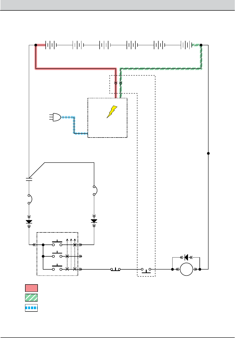
4-30 T16 Service Information 9008149 (1-11)
TROUBLESHOOTING
+ - + - + - + - + - + -
J3-5 Brush LT+
D-3
OBC002
O Board
Battery Charger
6 Volt
Key Switch
IGN
15
ACC
30
BATT
75
50 Start S-2
E-Stop
Switch
S-3 Charger
Interlock Switch
(N.C.)
ST
M1B
M1A
Battery Positive +
Battery Negative -
D-4
D-2
Charger
Connector
6 Volt 6 Volt 6 Volt 6 Volt 6 Volt
CB2
2.5A
1/RED
RED BLACK
AC Plug
13/BLK
6/BLU 7/PUR 8/GRY
3/ORA 4/YEL
Cable to Ground Stand O
5/GRN
10/TAN
2/BRNCable
AC Volts
O Board Battery Charging ON

T16 Service Information 9008149 (1-11) 4-31
TROUBLESHOOTING
Batteries Failed to Charge
STEP ACTION VALUES YES NO
1Key O
Check AC power supply
Is the rated AC supply voltage present?
•
•
•
Go to Step #2 Check AC
Supply Circuit
Protection
2Key O
Disconnect batteries
Unplug charger from AC supply
Check charger fuse or circuit breaker (if equipped)
Is a fuse blown or circuit breaker tripped?
•
•
•
•
•
Replace Fuse
or Reset
Circuit Breaker
and Test Char-
ger Operation
Go to Step #3
3Key O
Inspect battery and charger cables for damage, cor-
rosion, contamination or terminal problems
Do any of the above conditions exist?
•
•
•
Repair or Re-
place Battery
and/or Char-
ger Cables
Go to Step #4
4Skip this step for sealed, AGM, or gel batteries
Key O
Disconnect batteries
Check water level of all battery cells
Are the lead plates submerged?
•
•
•
•
•
Go to Step #5 Add Distilled
Water Until
Lead Plates are
Covered.
5Key O
Load test all batteries (AGM, Gel, Lead-Acid)
-or-
Test specic gravity of each cell using a hydrometer
or refractometer ((Lead-Acid)
Do the batteries pass a load test or are all battery
cells within 0.050 (50 points) specic gravity of each
other?
•
•
•
•
•
Replace Bat-
tery Charger
Replace
Battery or Bat-
teries
Terms:
AC = Alternating Current
AGM = Absorbed Glass Mat
Specic Gravity = Relative density of a substance compared to water (water = 1.000 specic gravity)
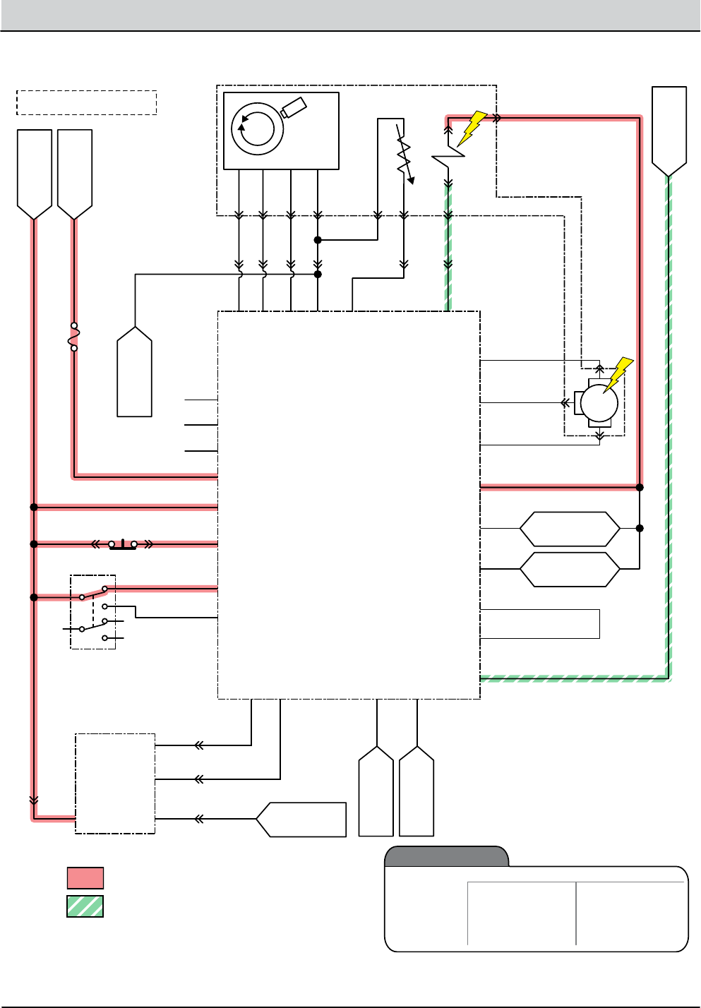
4-32 T16 Service Information 9008149 (1-11)
TROUBLESHOOTING
B- From
Stando
S-5 Seat Switch (N.O.)
Amer
Encoder
Cable
Battery Positive +
Battery Negative -
FU1
100A
Switched B+
From Buss Bar
Switched B+
To: CAN Open-
(J6-14)
To: Throttle
Sensor (GND)
To: Curtis 1234
(I/O GND)
To: CAN Open+
(J6-13)
To: Back-Up
Light Circuit
To: Back-Up
Alarm Circuit
PMC012
FWD
REV
6
2
8
BA
5
4 J1-33
GND Cable
J1-34
J1-21
W/WHT
V/GRN
U/ORN
J1-3
J1-4
J1-13
J1-11
BLU2 J1-32
J1-26
J1-31
J1-7
J1-18
J1-15
66/BLU
61/PNK
62/BRN
12/BRN
17/PUR
Propel Motor Assembly
17/PUR
15/GRN
87/PUR
Temp Sender
Brake
Solenoid
59/WHT
58GRY
RED1
WHT5
BLK6
YEL
T2
B1 B2
T1
YEL
J1-16
J1-35
J1-23
P1-C
BLU
YEL
P1-B
P1-D
BLK
P1-A
RED
J1-22
J1-9
J1-1
B+
J1-29
J1-28
J1-25
1
MTR
Curtis 1234
Controller
PROG +
TX
RX
B+
KSI
INTERLOCK
FWD
FWD/REV Switch
Throttle Sensor
REV
B -
GND
B+
THROTTLE
BRAKE
CAN TERM L
CAN TERM H
U
DRV3
DRV4
DRV1
THERMISTOR
I/O GND
PHASE A
PHASE B
+5V
DRV2
COIL RETURN
V
W
BRAKE IN
(0-5 vdc)
(0-5 vdc) THROTTLE
CAN L
8/GRY 8/GRY
18/GRY
16/BLU
94/YEL
9/WHT
11/PNK
14/YEL
58/GRY
58/GRY
CAN H
Note: Key Switch ON
Electro-
Magnetic
Brake
Enabled (Applied)
• Key O
• E-Stop Switch Open (Up)
• Neutral (1-2 Second Delay)
• Seat Switch Open
• Curtis 1234 Fault
• Key ON
•E-Stop Switch Closed (Down)
• Throttle Command
• Seat Switch Closed
Disabled (Released)
Operational Matrix:
Parking Brake, Electromagnetic (Released)

T16 Service Information 9008149 (1-11) 4-33
TROUBLESHOOTING
Parking Brake Failed to Release/Apply
STEP ACTION VALUES YES NO
1Key On
Is there a pertinent LCD warning or fault message
displayed?
•
•
See “LCD
Warnings” or
“LCD Faults”
Sections
Go to Step #2
2Key On
See “Curtis 1234 Controller Diagnostics” section
Is there a pertinent Curtis 1234 fault displayed?
•
•
•
Correct Fault
Condition
Go to Step #3
3Key O
See “Propel Diagnostic Mode”
Is P1:Curtis Online?
Does P2:Throttle input voltage (0-5 vdc) change pro-
portionally with throttle pedal movement?
Does P3:Brake pedal input turn On/O with brake
pedal activation?
Does P4:Direction input correspond with Fwd/Rev
rocker switch position?
Does P5:Speed input from drive assembly encoder
(speed, direction, position sensor) read “0000.0
Mph?”
Does P8:Propel motor current read “0000.0 Amps?”
Is the answer “Yes” to all of the above?
•
•
•
•
•
•
•
•
•
Go to Step #4 Correct Faulty
Input Condi-
tion
4Key O
See TESTING PARKING BRAKE, ELECTROMAGNETIC
in the SERVICE section of this manual
Does the brake pass the testing?
•
•
•
See TEST-
ING PARK-
ING BRAKE,
ELECTROMAG-
NETIC
Go to Step #5 Repair or Re-
place Parking
Brake Assem-
bly
5Reconnect parking brake assembly to propel harness
Key On
Disable(Release) brake
Test voltage applied to the parking brake as shown
on the electrical schematic
Are the electrical circuits operating as shown on the
electrical schematic?
•
•
•
•
•
Go Back to
Step #1
Identify Volt-
age Drop
Location and
Repair or Re-
place Neces-
sary Compo-
nents
Terms:
LCD = Liquid Crystal Display

4-34 T16 Service Information 9008149 (1-11)
TROUBLESHOOTING
+ - + - + - + - + - + -
T16
Control
Board
6 Volt
Key Switch
IGN
15
ACC
30
BATT
Switched B+
From Buss Bar
75
50 Start S-2
E-Stop
Switch
S-3
Charger
Interlock
ST
M1B
M1A
J7-12 Detergent Metering
J3-5 Brush LT+
J7-1
B+(Control)
B+ B-
Battery Positive +
Battery Negative -
D-4
D-2 D-3
CB1
2.5A
*Detergent
Pump
CB5 (2.5A)
FU2
100A
6 Volt 6 Volt 6 Volt 6 Volt 6 Volt
CB2
2.5A
1/RED
13/BLK
6/BLU
145/GRN44/YEL
2/BRN
7/PUR
Cable Cable
MTR
3/ORA
8/GRY
4/YEL
Cable to Ground Stand O
5/GRN
10/TAN
2/BRNCable
DMP001
Detergent
Metering
Enabled
• 1-STEP Scrub ON
• Solution Control ON
(Conventional Only)
• 2 or 3 Solution LEDs ON
• Fwd/Rev Propel
• 1-STEP Scrub OFF
• Solution Control OFF
•0 or 1 Solution LEDs ON
• Neutral-Ready State
• Recovery Tank Full
• Solution Tank Empty
• Very Low Batt Voltage
• Load Current Fault
Disabled
Operational Matrix:
* Detergent Pump Voltages
Range
Economy 2-LEDs
3-LEDs
2-LEDs
3-LEDs
2-LEDs
3-LEDs
10%
14%
14%
26%
26%
68%
3.6 Volts
5.1 Volts
(+/- 20%)
5.1 Volts
9.4 Volts
(+/- 20%)
9.4 Volts
24.5 Volts
(+/- 20%)
Normal
(Default)
Heavy
Level PWM% @ Nominal
36 VDC
NOTE: PWM% too low to measure using DVOM.
Use a test light and check for on/o ash at the
detergent pump connection.
Detergent Metering ON (Option)

T16 Service Information 9008149 (1-11) 4-35
TROUBLESHOOTING
Detergent Metering Failed to Turn ON
STEP ACTION VALUES YES NO
1Key On
Enable detergent metering subsystem
Is there a pertinent LCD warning or fault message
displayed?
•
•
•
See “LCD
Warnings” or
“LCD Faults”
Sections
Go to Step #2
2Key O
Firmly press circuit breaker #5 to reset
Was circuit breaker #5 tripped?
•
•
•
Reset Circuit
Breaker and
Test Deter-
gent Metering
Operation
Go to Step #3
3Key O
See “Self-Test Mode”
Does the Self-Test display output circuit J7-12 as
open or shorted?
•
•
•
Correct Open
or Short Cir-
cuit Condition
Go to Step #4
4Key O
Disconnect detergent metering pump from main
harness
Apply battery voltage to detergent metering pump
using fuse-protected jumper leads
Does the detergent metering pump dispense deter-
gent?
•
•
•
•
Go to Step #5 Replace Deter-
gent Metering
Pump
5Key O
Reconnect detergent metering pump to main har-
ness
Key On
Enable detergent metering subsystem
Test voltage applied to the detergent metering sub-
system as shown on the electrical schematic
Are the electrical circuits operating as shown on the
electrical schematic?
•
•
•
•
•
•
Go Back to
Step #1
Identify Volt-
age Drop
Location and
Repair or Re-
place Neces-
sary Compo-
nents
Terms:
LCD = Liquid Crystal Display
J7-12 = T16 Control Board Connector #7, Pin #12

4-36 T16 Service Information 9008149 (1-11)
TROUBLESHOOTING
+ - + - + - + - + - + -
T16
Control
Board
6 Volt
Key Switch
IGN
15
ACC
30
BATT
Switched B+
From Buss Bar
75
50 Start S-2
E-Stop
Switch
S-3
Charger
Interlock
ST
M1B
M2B
M1A
MTR
ES Pump
*SOL. Tank
Pressure
Sensor
REC. Tank
1/2 Full Sw.
M2A J7-10 ES Relay
SOL Level J6-3
+12VDC J7-20
REC 1/2 Full J6-5
J3-5 Brush LT+
J7-1
B+(Control)
B+ B-
Battery Positive +
Battery Negative -
D-4
D-5
D-2 D-3
CB1
2.5A
CB4
(2.5A) ES Relay
FU2
100A
6 Volt 6 Volt 6 Volt 6 Volt 6 Volt
CB2
2.5A
1/RED
13/BLK
6/BLU
43/ORA39/WHT
CB7 (15A) 63/ORA 13/BLK
53/ORA
51/
PNK
49/
WHT
60/TAN
30 87
86 85
2/BRN
7/PUR
Cable Cable
3/ORA
8/GRY
4/YEL
Cable to Ground Stand O
5/GRN
10/TAN
2/BRNCable
ESC001
A
A
B
B
C
C
Extended
Scrub
Enabled
• 1-STEP Scrub ON
• Solution Control ON
• ES Button ON
• Recovery Tank 1/2 Full
• 1-STEP Scrub OFF
• Solution Control OFF
• ES Button OFF
• Solution Tank Full
• Recovery Tank Full
• Very Low Batt Voltage
• Load Current Fault
Disabled
Operational Matrix:
*Solution Tank Sensor Output
Tank Level
0% (Empty)
20%
40%
60%
80%
100% (Tank Full)
1.0 - 1.17 Volts
1.17 - 1.6 Volts
1.6 - 1.89 Volts
1.89 - 2.25 Volts
2.25 - 2.4 Volts
2.4 + Volts
Voltage (at J6-3)
Extended Scrub ON (Option)

T16 Service Information 9008149 (1-11) 4-37
TROUBLESHOOTING
Extended Scrub Failed to Turn ON
STEP ACTION VALUES YES NO
1Key On
Enable ES (Extended Scrub) subsystem
Is there a pertinent LCD warning or fault message
displayed?
•
•
•
See “LCD
Warnings” or
“LCD Faults”
Sections
Go to Step #2
2Key O
Firmly press circuit breaker #4 to reset
Firmly press circuit breaker #7 to reset
Was a circuit breaker tripped?
•
•
•
•
Reset Circuit
Breaker(s)
and Test ES
Subsystem
Operation
Go to Step #3
3Key O
See “Manual Mode” section of this manual
Activate the ES pump in manual mode
Does the ES pump turn On?
•
•
•
•
Go to Step #6 Go to Step #4
4Key O
See “Self-Test Mode” section of this manual
Does the Self-Test display output circuit J7-10 as
open or shorted?
•
•
•
Correct Open
or Short Cir-
cuit Condition
Go to Step #5
5Key O
Disconnect ES pump from main harness
Apply battery voltage to ES pump using fuse-pro-
tected jumper leads
Does the ES pump turn On and transfer solution
from the recovery tank to the solution tank?
•
•
•
•
Go to Step #6 Replace ES
Pump
6Key O
Reconnect ES pump to main harness
Key On
Enable ES subsystem
Test voltage applied to the ES subsystem as shown
on the electrical schematic
Are the electrical circuits operating as shown on the
electrical schematic?
•
•
•
•
•
•
Go Back to
Step #1
Identify Volt-
age Drop
Location and
Repair or Re-
place Neces-
sary Compo-
nents
Terms:
ES = Extended Scrub
LCD = Liquid Crystal Display
J7-10 = T16 Control Board Connector #7, Pin #10

4-38 T16 Service Information 9008149 (1-11)
TROUBLESHOOTING
B- From
Stando
Battery Positive +
Battery Negative -
75/GRN
Switched B+
From Buss Bar
ELC001
Light Switch Position
Lights OFF/Down = 2-1, 6-5
Headlight ON/Center = 2-3, 6-7
Headlight and Flashing ON/Up = 3-4, 7-8
1
3
5
7
2
4
6
8
76/BLU76/BLU
93/ORA
92/BRN
78/GRY
77/PUR
13/BLK 13/BLK
13/BLK
13/BLK
102/BRN
FU1
100A
Note: Key Switch ON
CB11
(15A) CB12 (2.5A)
Center
Headlight (LED)
Red Taillight (LED)
Red Taillight (LED)
Pre-Sweep
Option Only
OHG Flash/
Strobe Light
CB13 (2.5A)
CB15
(2.5A)
LT6
Flash/Strobe Light
LT7
LT2
LT1
LT4
LT3
Pre-Sweep LH
Headlight (LED)
Pre-Sweep RH
Headlight (LED)
Lighting ON

T16 Service Information 9008149 (1-11) 4-39
TROUBLESHOOTING
Lighting Failed to Turn ON
STEP ACTION VALUES YES NO
1Key On
Light switch On
Firmly press circuit breaker #11 to reset
Is circuit breaker #11 tripped?
•
•
•
•
Reset and
Test Lighting
Operation
Go to Step #2
2Key On
Light switch On
Firmly press circuit breaker #12 (Option) to reset
Is circuit breaker #12 tripped?
•
•
•
•
Reset and
Test Lighting
Operation
Go to Step #3
3Key On
Light switch On
Firmly press circuit breaker #13 (Option) to reset
Is circuit breaker #13 tripped?
•
•
•
•
Reset and
Test Lighting
Operation
Go to Step #4
4Key On
Light switch On
Firmly press circuit breaker #15 (Option) to reset
Is circuit breaker #15 tripped?
•
•
•
•
Reset and
Test Lighting
Operation
Go to Step #5
5Key On
Light switch On
Test voltage applied to the lighting subsystem as
shown on the electrical schematic
Are the electrical circuits operating as shown on the
electrical schematic?
•
•
•
•
Go Back to
Step #1
Identify Volt-
age Drop
Location and
Repair or Re-
place Neces-
sary Compo-
nents

4-40 T16 Service Information 9008149 (1-11)
TROUBLESHOOTING
+ - + - + - + - + - + -
1
2
2
1
T16
Control
Board
6 Volt
Key Switch
IGN
15
ACC
30
BATT
Switched B+
From Buss Bar
75
50 Start S-2
E-Stop
Switch
S-3
Charger
Interlock
ST
M1B
M1A
MTR J3-1 Brush RT+
J3-2 Brush RT-
J3-6 Brush LT-
J3-5 Brush LT+
Rear/Right Brush
Front*/Left Brush
*Front Cylindrical = Uses Adaptor
J7-1
B+(Control)
B+
B-
Battery Positive +
Battery Negative -
D-4
D-2 D-3
CB1
2.5A
FU2
100A
6 Volt 6 Volt 6 Volt 6 Volt 6 Volt
CB2
2.5A
1/RED
13/BLK
6/BLU 7/PUR
Cable
Cable
21/PNK
22/BRN
MTR 26/BLU
25/GRN
3/ORA
8/GRY
4/YEL
Cable to Ground Stand O
5/GRN
10/TAN
2/BRNCable
MSC001
12
12
Main Scrub
Brushes
Enabled
• 1-STEP Scrub ON
• Fwd/Rev Propel • 1-STEP Scrub OFF
• Neutral-Ready State
• Recovery Tank Full
• Solution Tank Empty
• Very Low Batt Voltage
• Load Current Fault
Disabled
Operational Matrix:
Main Scrub Brushes ON

T16 Service Information 9008149 (1-11) 4-41
TROUBLESHOOTING
Main Scrub Brushes Failed to Turn ON
STEP ACTION VALUES YES NO
1Key On
Enable main scrub brushes subsystem
Is there a pertinent LCD warning or fault message
displayed?
•
•
•
See “LCD
Warnings” or
“LCD Faults”
Sections
Go to Step #2
2Key O
See “Manual Mode” section of this manual
Activate the main scrub brushes in manual mode
Do the scrub brushes turn On?
•
•
•
•
Go to Step #6 Go to Step #3
3Key O
See “Self-Test Mode”
Does the Self-Test display output circuits J3-1, J3-2,
J3-5, or J3-6 as open or shorted?
•
•
•
Correct Open
or Short Cir-
cuit Condition
Go to Step #4
4Proceed to Step #5 for disk scrub head models
Key O
Remove cylindrical brushes from scrub head
Check for worn out brushes (see maintenance sec-
tion)
Check brushes for entangled debris
Check brush idler plugs and bearings for excessive
wear, damage, seizure, etc.
Check main brush drive belts for excessive wear,
damage, etc
Do any of the above conditions exist?
•
•
•
•
•
•
•
•
Repair or Re-
place Neces-
sary Cylindri-
cal Scrub Head
Components
Go to Step #5
5Key O
See TESTING MAIN SCRUB BRUSH MOTORS in the
SERVICE section of this manual
Do the scrub brush motors pass the testing?
•
•
•
See TESTING
MAIN SCRUB
BRUSH MO-
TORS
Go to Step #6 Repair or
Replace Main
Scrub Brush
Motors
6Key O
Reconnect main scrub brush motors to main harness
Key On
Enable main scrub brush motors
Test voltage applied to the main scrub brush motor
subsystem as shown on the electrical schematic
Are the electrical circuits operating as shown on the
electrical schematic?
•
•
•
•
•
•
Go Back to
Step #1
Identify Volt-
age Drop
Location and
Repair or Re-
place Neces-
sary Compo-
nents
Terms:
LCD = Liquid Crystal Display
J3-1 = T16 Control Board Connector #3, Pin #1
J3-2 = T16 Control Board Connector #3, Pin #2
J3-5 = T16 Control Board Connector #3, Pin #5
J3-6 = T16 Control Board Connector #3, Pin #6

4-42 T16 Service Information 9008149 (1-11)
TROUBLESHOOTING
Power-Up ON
+ - + - + - + - + - + -
T16
Control
Board
6 Volt
Key Switch
IGN
15
ACC
30
BATT
Switched B+
From Buss Bar
75
50 Start S-2
E-Stop
Switch
S-3
Charger
Interlock
ST
M1B
M1A
J7-1
B+(Control)
B+
B-
Battery Positive +
(Key - On Position)
Battery Positive +
(Key - Start Position)
CAN +12V J2-1
J2-2
J2-3
J2-4
RED #1
RED #2
BLK #2
BLK #1
CAN +
CAN -
CAN GROUND
D-4
D-2 D-3
CB1
2.5A
FU2
100A
6 Volt 6 Volt 6 Volt 6 Volt 6 Volt
CB2
2.5A
1/RED
13/BLK
6/BLU 7/PUR
Cable
Shield
Instrument Panel Assembly
Cable
3/ORA
8/GRY
4/YEL
Cable to Ground Stand O
5/GRN
10/TAN
2/BRNCable
Battery Negative -
PUC001
NOTE: The power-up circuit is a
latching type circuit. The “50” terminal
of the key switch is the primary supply
and the “30” terminal is the secondary
supply after the M1B contacts close.
Tennant Quantum
UI ver X.X

T16 Service Information 9008149 (1-11) 4-43
TROUBLESHOOTING
Machine Failed to Power Up
STEP ACTION VALUES YES NO
1Key in Start Position
Test the total battery voltage using a voltmeter
Is the total battery voltage greater than 30 VDC?
•
•
•
Go to Step #2 Recharge
Batteries and
Test Power-Up
Circuit Opera-
tion
2Key O
Firmly press circuit breaker #2 to reset
Is circuit breaker #2 tripped?
•
•
•
Reset and Test
Power-Up Cir-
cuit Operation
Go to Step #3
3Key O
Firmly press circuit breaker #1 to reset
Is circuit breaker #1 tripped?
•
•
•
Reset and Test
Power-Up Cir-
cuit Operation
Go to Step #4
4Key O
Inspect fuse #2 (100 Amp)
Is fuse #2 blown?
•
•
•
Identify Cause
of Circuit
Overload and
Replace Fuse
Go to Step #5
5Cycle key switch from Start to On Position
Test voltage applied to the power-up subsystem as
shown on the electrical schematic
Are the electrical circuits operating as shown on the
electrical schematic?
•
•
•
Go Back to
Step #1
Identify Volt-
age Drop
Location and
Repair or Re-
place Neces-
sary Compo-
nents
Terms:
VDC = DC Voltage

4-44 T16 Service Information 9008149 (1-11)
TROUBLESHOOTING
Pre-Sweep Brushes ON (Option)
Switched B+
From Buss Bar
Switched B+
Note: Key Switch ON
B- From
Stando
T16
Control
Board
Battery Positive +
Battery Negative -
FU2
100A
M4A
86 85
B+
J7-1 B+ Control
B-
Cable
8/GRY
102/BRN
Cable
Pre-Sweep
Brush Relay
CB3 (2.5A)
CB8 (20A)
J7-4 Sweep
Note:
Pre-Sweep Enable:
J6-10 B+ = Sweep Enable ON
Sweep Enable J6-10
37/PUR 38/GRY
2/BRN
Switched B+
From Buss Bar
PSB001
Pre-Sweep Switch Position
Sweep OFF/Down = 2-1, 6-5
Sweep ON/Center = 2-3, 6-7
Vac & Sweep ON/Up = 3-4, 7-8
1
3
5
7
2
4
6
8
M4B
MTR
MTR
MTR
D-9
D-11
67/PUR
72/BRN
RH Side Broom Motor
LH Side Broom Motor
Main Broom Motor
13/BLK
13/BLK
65/GRN
65/GRN
68/GRY
69/WHT
30 87
FU1
100A
CB16 (15A)
Pre-Sweep
Brushes
Enabled
• Pre-Sweep Switch ON
• Fwd/Rev Propel
• Pre-Sweep Switch OFF
• Neutral-Ready State
• Very Low Battery Voltage
• Load Current Fault
Disabled
Operational Matrix:

T16 Service Information 9008149 (1-11) 4-45
TROUBLESHOOTING
Pre-Sweep Brushes Failed to Turn ON (Option)
STEP ACTION VALUES YES NO
1Key On
Enable Pre-Sweep brushes subsystem
Is there a pertinent LCD warning or fault message
displayed?
•
•
•
See “LCD
Warnings” or
“LCD Faults”
Sections
Go to Step #2
2Key O
See “Manual Mode” section of this manual
Activate the Pre-Sweep brushes in manual mode
Do the Pre-Sweep brushes turn On?
•
•
•
•
Go to Step #8 Go to Step #3
3Key O
See “Self-Test Mode”
Does the Self-Test display output circuit J7-4 as open
or shorted?
•
•
•
Correct Open
or Short Cir-
cuit Condition
Go to Step #4
4Key O
Firmly press circuit breaker #3 to reset
Is circuit breaker #3 tripped?
•
•
•
Reset and Test
Pre-Sweep
Brushes Op-
eration
Go to Step #5
5Key O
Firmly press circuit breaker #8 to reset
Is circuit breaker #8 tripped?
•
•
•
Reset and Test
Pre-Sweep
Brushes Op-
eration
Go to Step #6
6Key O
Firmly press circuit breaker #16 to reset
Is circuit breaker #16 tripped?
•
•
•
Reset and Test
Pre-Sweep
Brushes Op-
eration
Go to Step #7
7Key O
See TESTING MAIN SWEEP BROOM MOTOR in the
SERVICE section of this manual
See TESTING SIDE BRUSH MOTOR(S) (Pre-Sweep) in
the SERVICE section of this manual
Does each Pre-Sweep brush motor pass the testing?
•
•
•
•
Go to Step #8 Repair or
Replace Pre-
Sweep Brush
Motor(s)
8Key On
Test voltage applied to the Pre-Sweep subsystem as
shown on the electrical schematic
Are the electrical circuits operating as shown on the
electrical schematic?
•
•
•
Go Back to
Step #1
Identify Volt-
age Drop
Location and
Repair or Re-
place Neces-
sary Compo-
nents
Terms:
LCD = Liquid Crystal Display
J7-4 = T16 Control Board Connector #7, Pin #4

4-46 T16 Service Information 9008149 (1-11)
TROUBLESHOOTING
Pre-Sweep Brushes Down, OFF (Option)
B- From
Stando
Battery Positive +
Battery Negative -
68/GRY
Note: Key Switch ON
Switched B+
From Buss Bar
PSL001
Pre-Sweep Switch Position
Sweep OFF/Down = 2-1, 6-5
Sweep ON/Center = 2-3, 6-7
Vac & Sweep ON/Up = 3-4, 7-8
1
3
5
7
2
2
1
4
6
8
D-11
13/BLK
102/BRN
65/GRN
71/PNK
69/WHT MTR
Pre-Sweep
Lift Actuator
Extend
Limit Sw.
Retract
Limit Sw.
Red
Black
FU1
100A
CB16
(15A)
Pre-Sweep
Brushes Down
Enabled
• Pre-Sweep Switch ON • Pre-Sweep Switch OFF
Disabled
Operational Matrix:

T16 Service Information 9008149 (1-11) 4-47
TROUBLESHOOTING
Pre-Sweep Brushes Failed to Lower (Option)
STEP ACTION VALUES YES NO
1Key On
Pre-Sweep switch On
Firmly press circuit breaker #16 to reset
Is circuit breaker #16 tripped?
•
•
•
•
Reset and Test
Pre-Sweep Lift
Operation
Go to Step #2
2Key O
See TESTING PRE-SWEEP LIFT ACTUATOR in the SER-
VICE section of this manual
Does the Pre-Sweep lift actuator pass the testing?
•
•
•
See TESTING
PRE-SWEEP
LIFT ACTUA-
TOR
Go to Step #3 Replace Pre-
Sweep Lift
Actuator
3Key On
Pre-Sweep switch On
Test voltage applied to the Pre-Sweep lift subsystem
as shown on the electrical schematic
Are the electrical circuits operating as shown on the
electrical schematic?
•
•
•
•
Go Back to
Step #1
Identify Volt-
age Drop
Location and
Repair or Re-
place Neces-
sary Compo-
nents

4-48 T16 Service Information 9008149 (1-11)
TROUBLESHOOTING
Pre-Sweep Brushes Up, OFF (Option)
B- From
Stando
Battery Positive +
Battery Negative -
68/GRY
Note: Key Switch ON
Switched B+
From Buss Bar
PSL002
Pre-Sweep Switch Position
Sweep OFF/Down = 2-1, 6-5
Sweep ON/Center = 2-3, 6-7
Vac & Sweep ON/Up = 3-4, 7-8
1
3
5
7
2
2
1
4
6
8
D-11
13/BLK
102/BRN
65/GRN
71/PNK
69/WHT MTR
Pre-Sweep
Lift Actuator
Extend
Limit Sw.
Retract
Limit Sw.
Red
Black
FU1
100A
CB16
(15A)
Pre-Sweep
Brushes Up
Enabled
• Pre-Sweep Switch ON• Pre-Sweep Switch OFF
Disabled
Operational Matrix:

T16 Service Information 9008149 (1-11) 4-49
TROUBLESHOOTING
Pre-Sweep Brushes Failed to Raise (Option)
STEP ACTION VALUES YES NO
1Key On
Pre-Sweep switch On
Firmly press circuit breaker #16 to reset
Is circuit breaker #16 tripped?
•
•
•
•
Reset and Test
Pre-Sweep Lift
Operation
Go to Step #2
2Key O
See TESTING PRE-SWEEP LIFT ACTUATOR in the SER-
VICE section of this manual
Does the Pre-Sweep lift actuator pass the testing?
•
•
•
See TESTING
PRE-SWEEP
LIFT ACTUA-
TOR
Go to Step #3 Replace Pre-
Sweep Lift
Actuator
3Key On
Pre-Sweep switch On
Test voltage applied to the Pre-Sweep lift subsystem
as shown on the electrical schematic
Are the electrical circuits operating as shown on the
electrical schematic?
•
•
•
•
Go Back to
Step #1
Identify Volt-
age Drop
Location and
Repair or Re-
place Neces-
sary Compo-
nents

4-50 T16 Service Information 9008149 (1-11)
TROUBLESHOOTING
Propel Subsystem, Forward
B- From
Stando
S-5 Seat Switch (N.O.)
Amer
Encoder
Cable
Battery Positive +
Battery Negative -
FU1
100A
Switched B+
From Buss Bar
Switched B+
To: CAN Open-
(J6-14)
To: Throttle
Sensor (GND)
To: Curtis 1234
(I/O GND)
To: CAN Open+
(J6-13)
To: Back-Up
Light Circuit
To: Back-Up
Alarm Circuit
PMC001
FWD
REV
6
2
8
BA
5
4 J1-33
GND Cable
J1-34
J1-21
W/WHT
V/GRN
U/ORN
J1-3
J1-4
J1-13
J1-11
BLU2 J1-32
J1-26
J1-31
J1-7
J1-18
J1-15
66/BLU
61/PNK
62/BRN
12/BRN
17/PUR
Propel Motor Assembly
17/PUR
15/GRN
87/PUR
Temp Sender
Brake
Solenoid
59/WHT
58GRY
RED1
WHT5
BLK6
YEL
T2
B1 B2
T1
YEL
J1-16
J1-35
J1-23
P1-C
BLU
YEL
P1-B
P1-D
BLK
P1-A
RED
J1-22
J1-9
J1-1
B+
J1-29
J1-28
J1-25
1
MTR
Curtis 1234
Controller
PROG +
TX
RX
B+
KSI
INTERLOCK
FWD
FWD/REV Switch
Throttle Sensor
REV
B -
GND
B+
THROTTLE
BRAKE
CAN TERM L
CAN TERM H
U
DRV3
DRV4
DRV1
THERMISTOR
I/O GND
PHASE A
PHASE B
+5V
DRV2
COIL RETURN
V
W
BRAKE IN
(0-5 vdc)
(0-5 vdc) THROTTLE
CAN L
8/GRY 8/GRY
18/GRY
16/BLU
94/YEL
9/WHT
11/PNK
14/YEL
58/GRY
58/GRY
CAN H
Note: Key Switch ON
Propel
Enabled
• Seat Switch Closed
• Foot Throttle
Command
• Fwd/Rev Switch Input
• Seat Switch Open
• Neutral-Ready State
• Brake Command
• Curtis 1234 Fault
Disabled
Operational Matrix:

T16 Service Information 9008149 (1-11) 4-51
TROUBLESHOOTING
Machine Failed to Propel
STEP ACTION VALUES YES NO
1Key On
See “Curtis 1234 Controller Diagnostics” section of
this manual
Does a Curtis 1234 controller fault condition exist?
•
•
•
Correct Fault
Condition
Go to Step #2
2Key O
See “Propel Diagnostic Mode”
Is P1:Curtis Online?
Does P2: Throttle input voltage (0-5 vdc) change
proportionally with throttle pedal movement?
Does P3 :Brake pedal input turn On/O with brake
pedal activation?
Does P4: Direction input correspond with Fwd/Rev
rocker switch position?
Does P5:Speed input from drive assembly encoder
(speed, direction, position sensor) read “0000.0
Mph?”
Does P8:Propel motor current read “0000.0 Amps?”
Is the answer “Yes” to all of the above?
•
•
•
•
•
•
•
•
•
Go to Step #3 Correct Faulty
Input Condi-
tion
3Key O
Place machine on jackstands so drive wheel is lifted
o the oor
Enable forward propel
Test voltage applied to the propel subsystem as
shown on the electrical schematic
Are the electrical circuits operating as shown on the
electrical schematic?
•
•
•
•
•
Go Back to
Step #1
Identify Volt-
age Drop
Location and
Repair or Re-
place Neces-
sary Compo-
nents
Terms:
LCD = Liquid Crystal Display
VDC = Direct Current Voltage

4-52 T16 Service Information 9008149 (1-11)
TROUBLESHOOTING
Rear Squeegee Down, OFF
+ - + - + - + - + - + -
T16
Control
Board
6 Volt
Key Switch
IGN
15
ACC
30
BATT
Switched B+
From Buss Bar
75
50 Start S-2
E-Stop
Switch
S-3
Charger
Interlock
ST
M1B
M1A
MTR J5-6 SQGE ACT 1
J7-1
B+(Control)
B+ B-
J5-5 SQGE ACT 2
Squeegee
Actuator
Battery Positive +
Battery Negative -
D-4
D-2 D-3
CB1
2.5A
FU2
100A
6 Volt 6 Volt 6 Volt 6 Volt 6 Volt
CB2
2.5A
1/RED
13/BLK
6/BLU 7/PUR
Cable Cable
36/BLU
Extend
Limit Sw.
Retract
Limit Sw.
35/GRN
Red
Black
3/ORA
8/GRY
4/YEL
Cable to Ground Stand O
5/GRN
10/TAN
2/BRNCable
RSL001
1
2
Squeegee
Down
Enabled
• 1-STEP Scrub ON
• Squeegee/Vac ON • 1-STEP Scrub OFF
• Squeegee/Vac OFF
• Reverse Propel
• Recovery Tank Full
• Very Low Batt Voltage
• Load Current Fault
Disabled
Operational Matrix:

T16 Service Information 9008149 (1-11) 4-53
TROUBLESHOOTING
Rear Squeegee Failed to Raise/Lower
STEP ACTION VALUES YES NO
1Key On
Enable rear squeegee down
Is there a pertinent LCD warning or fault message
displayed?
•
•
•
See “LCD
Warnings” or
“LCD Faults”
Sections
Go to Step #2
2Key O
See “Manual Mode” section of this manual
Activate the rear squeegee in manual mode
Does the rear squeegee raise/lower?
•
•
•
•
Go to Step #5 Go to Step #3
3Key O
See “Self-Test Mode”
Does the Self-Test display output circuits J5-5 and
J5-6 as open or shorted?
•
•
•
Correct Open
or Short Cir-
cuit Condition
Go to Step #4
4Key O
See TESTING REAR SQUEEGEE LIFT ACTUATOR in the
SERVICE section of this manual
Does the rear squeegee lift actuator pass the testing?
•
•
•
See TESTING
REAR SQUEE-
GEE LIFT
ACTUATOR in
the SERVICE
Go to Step #5 Replace Rear
Squeegee Lift
Actuator
5Key O
Reconnect rear squeegee lift actuator to main wire
harness
Test voltage applied to rear squeegee lift subsystem
as shown on the electrical schematic
Are the electrical circuits operating as shown on the
electrical schematic?
•
•
•
•
Go Back to
Step #1
Identify Volt-
age Drop
Location and
Repair or
Replace Neces-
sary Compo-
nents
Terms:
LCD = Liquid Crystal Display
J5-5 = T16 Controller Connector #5, Pin #5
J5-6 = T16 Controller Connector #5, Pin #6

4-54 T16 Service Information 9008149 (1-11)
TROUBLESHOOTING
+ - + - + - + - + - + -
T16
Control
Board
6 Volt
Key Switch
IGN
15
ACC
30
BATT
Switched B+
From Buss Bar
75
50 Start S-2
E-Stop
Switch
S-3
Charger
Interlock
ST
M1B
M1A
J7-1
B+(Control)
B+ B-
MTR
Scrub Head Lift Actuator
J5-2 Scrub Act. 1
Battery Positive +
Battery Negative -
J5-1 Scrub Act. 2
D-4
D-2 D-3
CB1
2.5A
FU2
100A
6 Volt 6 Volt 6 Volt 6 Volt 6 Volt
CB2
2.5A
1/RED
13/BLK
6/BLU 7/PUR
32/BRN
Cable Cable
31/PNK
3/ORA
8/GRY
4/YEL
Cable to Ground Stand O
5/GRN
10/TAN
2/BRNCable
MSL001
12
Note:
B+ @ 31/PNK = Retract/Down
B+ @ 32/BRN = Extend/Up
Scrub Head
Down
Enabled
• 1-STEP Scrub ON
• Fwd/Rev Propel • 1-STEP Scrub OFF
• Neutral-Ready State
• Recovery Tank Full
• Solution Tank Empty
• Very Low Batt Voltage
• Load Current Fault
Disabled
Operational Matrix:
Scrub Head Lift

T16 Service Information 9008149 (1-11) 4-55
TROUBLESHOOTING
Scrub Head Failed to Raise/Lower
STEP ACTION VALUES YES NO
1Key On
Enable scrub head down
Is there a pertinent LCD warning or fault message
displayed?
•
•
•
See “LCD
Warnings” or
“LCD Faults”
Sections
Go to Step #2
2Key O
See “Manual Mode” section of this manual
Activate the scrub head in manual mode
Does the scrub head raise/lower?
•
•
•
•
Go to Step #5 Go to Step #3
3Key O
See “Self-Test Mode”
Does the Self-Test display output circuits J5-1 and
J5-2 as open or shorted?
•
•
•
Correct Open
or Short Cir-
cuit Condition
Go to Step #4
4Key O
See TESTING MAIN BRUSH LIFT ACTUATOR in the
SERVICE section of this manual
Does the scrub head lift actuator pass the testing?
•
•
•
See TESTING
MAIN BRUSH
LIFT ACTUA-
TOR
Go to Step #5 Replace Scrub
Head Lift
Actuator
5Key O
Reconnect scrub head lift actuator to main wire har-
ness
Test voltage applied to scrub head lift subsystem as
shown on the electrical schematic
Are the electrical circuits operating as shown on the
electrical schematic?
•
•
•
•
Go Back to
Step #1
Identify Volt-
age Drop
Location and
Repair or Re-
place Neces-
sary Compo-
nents
Terms:
LCD = Liquid Crystal Display
J5-2 = T16 Controller Connector #5, Pin #2
J5-3 = T16 Controller Connector #5, Pin #1

4-56 T16 Service Information 9008149 (1-11)
TROUBLESHOOTING
Side Brush ON (Option)
+ - + - + - + - + - + -
T16
Control
Board
6 Volt
Key Switch
IGN
15
ACC
30
BATT
Switched B+
From Buss Bar
75
50 Start S-2
E-Stop
Switch
S-3
Charger
Interlock
ST
M1B
M1A
J7-1
B+(Control)
B+
B-
MTR
Side Brush Motor
Note:
Congurable Option
Side Scrub = 100% Battery VDC
Side Sweep = 50% Battery VDC
J3-4 Side Br -
Battery Positive +
Battery Negative -
J3-3 Side Br +
Side Brush
Enable J6-6
D-4
D-2 D-3
CB1
2.5A
FU2
100A
6 Volt 6 Volt 6 Volt 6 Volt 6 Volt
CB2
2.5A
1/RED
13/BLK
6/BLU 7/PUR
24/YEL
Cable
Cable
S-9
Side Brush
Switch
23/ORA
55/GRN
3/ORA
8/GRY
4/YEL
Cable to Ground Stand O
5/GRN
10/TAN
2/BRNCable
SBC001
12
ON
OFF
6
2
8
5
4
1
Side Brush
Enabled
• 1-STEP Scrub ON
• Side Brush Switch ON
• Fwd/Rev Propel
• 1-STEP Scrub OFF
• Side Brush Switch OFF
• Recovery Tank Full
• Solution Tank Empty
• Very Low Batt Voltage
• Load Current Fault
• Neutral (Ready State)
Disabled
Operational Matrix:

T16 Service Information 9008149 (1-11) 4-57
TROUBLESHOOTING
Side Brush Failed to Turn ON (Option)
STEP ACTION VALUES YES NO
1Key On
Enable side brush
Is there a pertinent LCD warning or fault message
displayed?
•
•
•
See “LCD
Warnings” or
“LCD Faults”
Sections
Go to Step #2
2Key O
See “Manual Mode” section of this manual
Activate the side brush in manual mode
Do the side brush turn On?
•
•
•
•
Go to Step #6 Go to Step #3
3Key O
See “Self-Test Mode”
Does the Self-Test display output circuits J3-3 and
J3-4 as open or shorted?
•
•
•
Correct Open
or Short Cir-
cuit Condition
Go to Step #4
4Key O
See “Input Display Mode”
Does I7: Side Br On/O input correspond with side
brush rocker switch position?
•
•
•
Go to Step #5 Correct Faulty
Input Condi-
tion
5Key O
See TESTING SIDE BRUSH MOTOR (NON PRE-SWEEP)
in the SERVICE section of this manual
Does the side brush motor pass the testing?
•
•
•
See TESTING
SIDE BRUSH
MOTOR (NON
PRE-SWEEP)
Go to Step #6 Replace Side
Brush Motor
6Key O
Reconnect side brush motor to main wire harness
Test voltage applied to side brush subsystem as
shown on the electrical schematic
Are the electrical circuits operating as shown on the
electrical schematic?
•
•
•
•
Go Back to
Step #1
Identify Volt-
age Drop
Location and
Repair or Re-
place Neces-
sary Compo-
nents
Terms:
LCD = Liquid Crystal Display
J3-4 = T16 Controller Connector #3, Pin #4
J3-3 = T16 Controller Connector #3, Pin #3

4-58 T16 Service Information 9008149 (1-11)
TROUBLESHOOTING
Side Brush Extend/Down, OFF (Option)
+ - + - + - + - + - + -
T16
Control
Board
6 Volt
Key Switch
IGN
15
ACC
30
BATT
Switched B+
From Buss Bar
75
50 Start S-2
E-Stop
Switch
S-3
Charger
Interlock
ST
M1B
M1A
J7-1
B+(Control)
B+
B-
Battery Positive +
Battery Negative -
Side Brush
Enable J6-6
D-4
D-2 D-3
CB1
2.5A
FU2
100A
6 Volt 6 Volt 6 Volt 6 Volt 6 Volt
CB2
2.5A
1/RED
13/BLK
6/BLU 7/PUR
Cable
Cable
S-9
Side Brush
Switch
55/GRN
3/ORA
8/GRY
4/YEL
Cable to Ground Stand O
5/GRN
10/TAN
2/BRNCable
SBED001
ON
OFF
MTR J5-4 SIDE ACT 1
J5-3 SIDE ACT 2
Side Brush
Actuator
34/YEL
Extend
Limit Sw.
Retract
Limit Sw.
33/ORA
Red
Black
1
2
6
2
8
5
4
1
Side Brush
Extend/Down
Enabled
• 1-STEP Scrub ON
• Side Brush Switch ON
• 1-STEP Scrub OFF
• Side Brush Switch OFF
• Recovery Tank Full
• Solution Tank Empty
• Very Low Batt Voltage
• Load Current Fault
Disabled
Operational Matrix:

T16 Service Information 9008149 (1-11) 4-59
TROUBLESHOOTING
Side Brush Failed to Extend/Lower (Option)
STEP ACTION VALUES YES NO
1Key On
Enable side brush extend/down
Is there a pertinent LCD warning or fault message
displayed?
•
•
•
See “LCD
Warnings” or
“LCD Faults”
Sections
Go to Step #2
2Key O
See “Manual Mode” section of this manual
Extend/Lower the side brush in manual mode
Does the side brush extend/lower?
•
•
•
•
Go to Step #6 Go to Step #3
3Key O
See “Self-Test Mode”
Does the Self-Test display output circuits J5-3 and
J5-4 as open or shorted?
•
•
•
Correct Open
or Short Cir-
cuit Condition
Go to Step #4
4Key O
See “Input Display Mode”
Does I7: Side Br On/O input correspond with side
brush rocker switch position?
•
•
•
Go to Step #5 Correct Faulty
Input Condi-
tion
5Key O
See TESTING SIDE BRUSH LIFT ACTUATOR in the SER-
VICE section of this manual
Does the side brush lift actuator pass the testing?
•
•
•
See TESTING
SIDE BRUSH
LIFT ACTUA-
TOR
Go to Step #6 Replace Side
Brush Lift
Actuator
6Key O
Reconnect side brush lift actuator to main wire har-
ness
Key On
Side brush extend/down enabled
Test voltage applied to side brush lift subsystem as
shown on the electrical schematic
Are the electrical circuits operating as shown on the
electrical schematic?
•
•
•
•
•
•
Go Back to
Step #1
Identify Volt-
age Drop
Location and
Repair or Re-
place Neces-
sary Compo-
nents
Terms:
LCD = Liquid Crystal Display
J5-4 = T16 Controller Connector #5, Pin #4
J5-3 = T16 Controller Connector #5, Pin #3

4-60 T16 Service Information 9008149 (1-11)
TROUBLESHOOTING
Side Brush Retract/Up, OFF (Option)
+ - + - + - + - + - + -
T16
Control
Board
6 Volt
Key Switch
IGN
15
ACC
30
BATT
Switched B+
From Buss Bar
75
50 Start S-2
E-Stop
Switch
S-3
Charger
Interlock
ST
M1B
M1A
J7-1
B+(Control)
B+
B-
Battery Positive +
Battery Negative -
Side Brush
Enable J6-6
D-4
D-2 D-3
CB1
2.5A
FU2
100A
6 Volt 6 Volt 6 Volt 6 Volt 6 Volt
CB2
2.5A
1/RED
13/BLK
6/BLU 7/PUR
Cable
Cable
S-9
Side Brush
Switch
55/GRN
3/ORA
8/GRY
4/YEL
Cable to Ground Stand O
5/GRN
10/TAN
2/BRNCable
SBED002
ON
OFF
MTR J5-4 SIDE ACT 1
J5-3 SIDE ACT 2
Side Brush
Actuator
34/YEL
Extend
Limit Sw.
Retract
Limit Sw.
33/ORA
Red
Black
1
2
6
2
8
5
4
1
Side Brush
Retract/Up
Enabled
• 1-STEP Scrub ON
• Side Brush Switch ON
• 1-STEP Scrub OFF
• Side Brush Switch OFF
• Recovery Tank Full
• Solution Tank Empty
• Very Low Batt Voltage
• Load Current Fault
Disabled
Operational Matrix:

T16 Service Information 9008149 (1-11) 4-61
TROUBLESHOOTING
Side Brush Failed to Retract/Raise (Option)
STEP ACTION VALUES YES NO
1Key On
Enable side brush retract/up
Is there a pertinent LCD warning or fault message
displayed?
•
•
•
See “LCD
Warnings” or
“LCD Faults”
Sections
Go to Step #2
2Key O
See “Self-Test Mode”
Does the Self-Test display output circuits J5-3 and
J5-4 as open or shorted?
•
•
•
Correct Open
or Short Cir-
cuit Condition
Go to Step #3
3Key O
See “Input Display Mode”
Does I7: Side Br On/O input correspond with side
brush rocker switch position?
•
•
•
Go to Step #4 Correct Faulty
Input Condi-
tion
4Key O
See TESTING SIDE BRUSH LIFT ACTUATOR in the SER-
VICE section of this manual
Does the side brush lift actuator pass the testing?
•
•
•
See TESTING
SIDE BRUSH
LIFT ACTUA-
TOR
Go to Step #5 Replace Side
Brush Lift
Actuator
5Key On
Side brush switch O
Test voltage applied to side brush lift subsystem as
shown on the electrical schematic
Are the electrical circuits operating as shown on the
electrical schematic?
•
•
•
•
Go Back to
Step #1
Identify Volt-
age Drop
Location and
Repair or Re-
place Neces-
sary Compo-
nents
Terms:
LCD = Liquid Crystal Display
J5-4 = T16 Controller Connector #5, Pin #4
J5-3 = T16 Controller Connector #5, Pin #3

4-62 T16 Service Information 9008149 (1-11)
TROUBLESHOOTING
Solution Control ON (Conventional)
+ - + - + - + - + - + -
T16
Control
Board
6 Volt
Key Switch
IGN
15
ACC
30
BATT
Switched B+
From Buss Bar
75
50 Start S-2
E-Stop
Switch
S-3
Charger
Interlock
ST
M1B
M1A
J7-5 MAIN H2O
J7-14 SIDE H2O (Option)
J7-1
B+(Control)
B+ B-
Battery Positive +
Battery Negative -
D-4
D-2 D-3
CB1
2.5A
CB4 (2.5A)
*SV2 Main Scrub
H2O Valve
SV4 Side Brush
H2O Valve
CB6 (2.5A)
FU2
100A
6 Volt 6 Volt 6 Volt 6 Volt 6 Volt
CB2
2.5A
1/RED
13/BLK
6/BLU
42/BRN39/WHT
47/PUR
46/BLU
2/BRN
7/PUR
Cable
Cable
Side Brush
Water Pump
MTR
3/ORA
8/GRY
4/YEL
Cable to Ground Stand O
5/GRN
10/TAN
2/BRNCable
CSC001
Solution
Control
(Conventional)
Enabled
• 1-STEP Scrub ON
• Solution Control ON
• Fwd/Rev Propel
• 1-STEP Scrub OFF
• Solution Control OFF
• Neutral-Ready State
• Recovery Tank Full
• Solution Tank Empty
• Very Low Batt Voltage
• Load Current Fault
Disabled
Operational Matrix:
* SV2 (J7-5) H2O Valve Voltages
Range
Low 1-LED
2-LEDs
3-LEDs
1-LED
2-LEDs
3-LEDs
1-LED
2-LEDs
3-LEDs
20%
30%
45%
30%
55%
80%
55%
80%
100%
7.2 Volts
10.8 Volts
16.2 Volts
10.8 Volts
19.8 Volts
28.8 Volts
19.8 Volts
28.8 Volts
36 Volts
Med
(Default)
High
Level PWM% @ Nominal
36 VDC

T16 Service Information 9008149 (1-11) 4-63
TROUBLESHOOTING
Solution Control Failed to Turn ON (Conventional)
STEP ACTION VALUES YES NO
1Key On
Enable solution control (conventional)
Is there a pertinent LCD warning or fault message
displayed?
•
•
•
See “LCD
Warnings” or
“LCD Faults”
Sections
Go to Step #2
2Key O
See “Manual Mode” section of this manual
Activate solution control in manual mode
Does the machine dispense water to the oor?
•
•
•
•
Go to Step #7 Go to Step #3
3Key O
See “Self-Test Mode”
Does the Self-Test display output circuits J7-5 or J7-
14 (side brush option) as open or shorted?
•
•
•
Correct Open
or Short Cir-
cuit Condition
Go to Step #4
4Key O
Firmly press circuit breaker #4 to reset
Is circuit breaker #4 tripped?
•
•
•
Reset and Test
Solution Con-
trol Operation
Go to Step #5
5Skip this step if not equipped with optional side
brush
Key O
Firmly press circuit breaker #6 to reset
Is circuit breaker #6 tripped?
•
•
•
•
Reset and Test
Solution Con-
trol Operation
Go to Step #6
6Key O
Disconnect SV2, SV4, and side brush water pump
from main wire harness (SV4 and water pump if
equipped with side brush)
Apply battery voltage to SV2, SV4, and side brush
water pump using fuse-protected jumper leads
Does the main brush and side brush dispense solu-
tion?
•
•
•
•
Go to Step #7 Repair or Re-
place SV2, SV4,
or Side Brush
Water Pump
7Key O
Reconnect SV2, SV4, and side brush water pump to
main wire harness
Key On
Enable solution control (conventional)
Test voltage applied to solution control subsystem as
shown on the electrical schematic
Are the electrical circuits operating as shown on the
electrical schematic?
•
•
•
•
•
•
Go Back to
Step #1
Identify Volt-
age Drop
Location and
Repair or Re-
place Neces-
sary Compo-
nents
Terms:
LCD = Liquid Crystal Display
J7-5 = T16 Controller Connector #7, Pin #5
J7-14 = T16 Controller Connector #7, Pin #14
SV2 = Solenoid Valve #2 (Main Brush)
SV4 = Solenoid Valve #4 (Side Brush)

4-64 T16 Service Information 9008149 (1-11)
TROUBLESHOOTING
Solution Control ON (ec-H2O)
Switched B+
From Buss Bar
B- From
Stando
C1 Capacitor (0.01Uf)
R1
(11 Ω/40W)
+-
ec-H2O
Pump
ec-H2O
Control
Module
T16
Control
Board
VCC_A
J7-12 ec-H2O Side Br. Flow
Alarm
Com N.C.
N.O.
S-14 Pressure Sw.
N.C. Opens @ 25 +/- 2 psi
Enable
GND_A
GND_B
Pressure IN
(ec-H2O SW)
(ec-H2O SW)
VCC_B
VCC_C
Pump
(SOL-A)
ec-H2O Valve
Sparger
e-Cell
65EA/BLU
5EA/GRN
8EA/GRY
7EA/PUR
3EA/ORA
4EA/YEL
(SOL-B)
(SPA-A)
(SPA-B)
(CELL-A)
(CELL-B)
(LED GND)
(LED RED)
(LED BLU)
Battery Positive +
Battery Negative -
D-8
FU2
100A
B+ B-
Cable Cable
SV3 ec-H2O Side Brush
H20 Valve
CB6 (2.5A)
J7-9 ec-H2O Side Brush
Note:
ec-H2O Enable:
J7-10 Low=Turn ON ecH2O
ec-H2O Enable J7-10
ec-H2O LED BLU
ec-H2O LED RED
46/BLU 48/GRY
CB9 (2.5A) 79/WHT
CB10 (2.5A)
145/GRN
Note:
ec-H2O Side Brush
J7-12 Low=SV3 H20 Valve ON
ec-H2O Pump ON 100%
13/BLK
88/GRY
9EA/WHT
S-15
Flush Switch
13EA/BLK
2/BRN
43/ORA
57/PUR
56/BLU
80/TAN
ECC001
MTR
10 4
1
3
2
7
9
6-4
6-8
5
6
11
12
8
6-1
6-2
6-3
6-6
6-5
6-7
Solution
Control
(ec-H2O)
Enabled
• 1-STEP Scrub ON
• Solution Control ON
• ec-H2O Button ON
• Fwd/Rev Propel
• 1-STEP Scrub OFF
• Solution Control OFF
• ec-H2O Button OFF
• Neutral-Ready State
• Recovery Tank Full
• Solution Tank Empty
• Very Low Batt Voltage
• ec-H2O System Fault
• Load Current Fault
Disabled
Operational Matrix:

T16 Service Information 9008149 (1-11) 4-65
TROUBLESHOOTING
Solution Control Failed to Turn ON (ec-H2O)
STEP ACTION VALUES YES NO
1Key On
Enable solution control (ec-H2O)
Is there a pertinent LCD warning or fault message
displayed?
•
•
•
See “LCD
Warnings” or
“LCD Faults”
Sections
Go to Step #2
2Key O
Firmly press circuit breakers #6, #9, and #10 to reset
Is a circuit breaker tripped?
•
•
•
Reset and Test
ec-H2O Solu-
tion Control
Operation
Go to Step #3
3Key O
Enable solution control (ec-H2O)
Is the ec-H2O LED ashing RED, indicating a system
restriction or low water conductivity*?
•
•
•
See “ec-H2O
Module Flush
Procedure”
Section. Then
Proceed to
Step #4
Go to Step #5
4Key O
See “ec-H2O Module Flush Procedure” section of this
manual
Did the ush procedure x the problem?
•
•
•
System OK See “Testing
ec-H2O Pres-
sure Switch”
5Key O
See “Manual Mode” section of this manual
Activate solution control (ec-H2O) in manual mode
Does solution control (ec-H2O) turn On?
•
•
•
•
Go to Step #8 Go to Step #6
6Key O
See “Self-Test Mode”
Does the Self-Test display output circuits J7-9, J7-10,
or J7-12 as open or shorted?
•
•
•
See “Self-Test
Mode”
Correct Open
or Short Cir-
cuit Condition
Go to Step #7
7Key O
Disconnect ec-H2O water pump from wire harness
Apply battery voltage to ec-H2O water pump using
fuse-protected jumper leads
Does the ec-H2O water pump dispense water?
•
•
•
•
Go to Step #8 Repair or Re-
place ec-H2O
Water Pump
8Key O
Reconnect ec-H2O water pump to wire harness
Key On
Enable solution control (ec-H2O)
Test voltage applied to solution control (ec-H2O)
system as shown on the electrical schematic
Are the electrical circuits operating as shown on the
electrical schematic?
•
•
•
•
•
•
Go to Step #9 Identify Volt-
age Drop
Location and
Repair or Re-
place Neces-
sary Compo-
nents
9Key On
Enable solution control (ec-H2O)
Is the ec-H2O LED solid RED, indicating an overcur-
rent condition on a system component?
•
•
•
Replace
ec-H2O
Module
Go Back to
Step #1
Terms:
LCD = Liquid Crystal Display
LED = Light Emitting Diode
J7-9 = T16 Controller Connector #7, Pin #9
*NOTE: Add 1/2 tablespoon of salt for every 10 gallons of water in the solution tank to increase water conductivity.
J7-10 = T16 Controller Connector #7, Pin #10
J7-12 = T16 Controller Connector #7, Pin #12

4-66 T16 Service Information 9008149 (1-11)
TROUBLESHOOTING
Solution Control ON (FaST)
+ - + - + - + - + - + -
T16 Control Board
6 Volt
Key Switch
IGN
15
ACC
30
BATT
Switched B+
From Buss Bar
75
50 Start S-2
E-Stop
Switch
S-3
Charger
Interlock
ST
M1B
M2B
M1A
MTR
FaST/ES Pump
M2A J7-10 FaST/ES/ecH2O Relay
J7-9 FaST/ecH2O Sidebrush
J3-5 Brush LT+
J7-1
B+(Control)
B+
B-
Battery Positive +
Battery Negative -
D-4
D-5
D-2 D-3
CB1
2.5A
CB4 (2.5A) FaST/ES Relay
SV3 FaST Side
Brush H2O Valve
CB6 (2.5A)
FU2
100A
6 Volt 6 Volt 6 Volt 6 Volt 6 Volt
CB2
2.5A
1/RED
13/BLK
6/BLU
43/ORA39/WHT
48/GRY46/BLU
CB7 (15A) 63/ORA 13/BLK60/TAN
30 87
86 85
2/BRN
7/PUR
Cable
Cable
3/ORA
8/GRY
4/YEL
Cable to Ground Stand O
5/GRN
10/TAN
2/BRNCable
FSC001
Solution
Control
(FaST)
Enabled
• 1-STEP Scrub ON
• Solution Control ON
• FaST Button ON
• Fwd/Rev Propel
• 1-STEP Scrub OFF
• Solution Control OFF
• FaST Button OFF
• Neutral-Ready State
• Recovery Tank Full
• Solution Tank Empty
• Very Low Batt Voltage
• Load Current Fault
Disabled
Operational Matrix:

T16 Service Information 9008149 (1-11) 4-67
TROUBLESHOOTING
Solution Control Failed to Turn ON (FaST)
STEP ACTION VALUES YES NO
1Key On
Enable solution control (FaST)
Is there a pertinent LCD warning or fault message
displayed?
•
•
•
See “LCD
Warnings” or
“LCD Faults”
Sections
Go to Step #2
2Key O
Firmly press circuit breakers #4, #6, and #7 to reset
Is a circuit breaker tripped?
•
•
•
Reset and Test
FaST Solution
Control Opera-
tion
Go to Step #3
3Key O
See “Manual Mode” section of this manual
Activate solution control (FaST) in manual mode
Does solution control (FaST) turn On?
•
•
•
•
Go to Step #6 Go to Step #4
4Key O
See “Self-Test Mode”
Does the Self-Test display output circuits J7-9 or J7-
10 as open or shorted?
•
•
•
Correct Open
or Short Cir-
cuit Condition
Go to Step #5
5Key O
See TESTING FaST PUMP in the SERVICE section of
this manual
Does the FaST water pump pass the testing?
•
•
•
See TESTING
FaST PUMP
Go to Step #6 Repair or
Replace FaST
Water Pump
6Key O
Reconnect FaST water pump to wire harness
Key On
Enable solution control (FaST)
Test voltage applied to solution control (FaST) sub-
system as shown on the electrical schematic
Are the electrical circuits operating as shown on the
electrical schematic?
•
•
•
•
•
•
Go Back to
Step #1
Identify Volt-
age Drop
Location and
Repair or Re-
place Neces-
sary Compo-
nents
Terms:
LCD = Liquid Crystal Display
J7-9 = T16 Controller Connector #7, Pin #9
J7-10 = T16 Controller Connector #7, Pin #10

4-68 T16 Service Information 9008149 (1-11)
TROUBLESHOOTING
Spray Nozzle ON (Option)
B- From
Stando
Battery Positive +
Battery Negative -
MTR
D-10
13/BLK
13/BLK
73/ORA
Switched B+
From Buss Bar
SNC001
6
10
2
8
9
5
4
1
13/BLK
Spray Nozzle Pump
Spray Nozzle Switch
74/YEL
74/YEL
102/BRN
FU1
100A
CB14
(15A)
Note: Key Switch ON

T16 Service Information 9008149 (1-11) 4-69
TROUBLESHOOTING
Spray Nozzle Failed to Turn ON (Option)
STEP ACTION VALUES YES NO
1Key On
Enable spray nozzle subsystem
Is there a pertinent LCD warning or fault message
displayed?
•
•
•
See “LCD
Warnings” or
“LCD Faults”
Sections
Go to Step #2
2Key O
Firmly press circuit breaker #14 to reset
Is circuit breaker #14 tripped?
•
•
•
Reset and Test
Spray Nozzle
Operation
Go to Step #3
3Key O
Disconnect spray nozzle water pump from wire har-
ness
Apply battery voltage to spray nozzle water pump
using fuse-protected jumper leads
Does the spray nozzle water pump dispense water?
•
•
•
•
Go to Step #4 Repair or
Replace Spray
Nozzle Water
Pump
4Key O
Reconnect spray nozzle water pump to wire harness
Key On
Turn spray nozzle switch On
Test voltage applied to spray nozzle subsystem as
shown on the electrical schematic
Are the electrical circuits operating as shown on the
electrical schematic?
•
•
•
•
•
•
Go Back to
Step #1
Identify Volt-
age Drop
Location and
Repair or Re-
place Neces-
sary Compo-
nents

4-70 T16 Service Information 9008149 (1-11)
TROUBLESHOOTING
Vacuum Fan(s), Scrubbing ON
+ - + - + - + - + - + -
T16
Control
Board
6 Volt
Key Switch
IGN
15
ACC
30
BATT
Switched B+
From Buss Bar
75
50 Start S-2
E-Stop
Switch
S-3
Charger
Interlock
ST
M1B
M1A
MTR J4-3 Vac 2+ (Option)
J7-1
B+(Control)
B+ B-
J4-4 Vac 2- (Option)
MTR
Vacuum Fan #1
Vacuum Fan #2
J4-1 Vac 1+
Battery Positive +
Battery Negative -
J4-2 Vac 1-
D-4
D-2 D-3
CB1
2.5A
FU2
100A
6 Volt 6 Volt 6 Volt 6 Volt 6 Volt
CB2
2.5A
1/RED
13/BLK
6/BLU 7/PUR
27/PUR
Cable Cable
28/GRY
29/WHT
30/TAN
3/ORA
8/GRY
4/YEL
Cable to Ground Stand O
5/GRN
10/TAN
2/BRNCable
VFC001
2 1
2 1
Vacuum Fan
Enabled
• 1-STEP Scrub ON
• Squeegee/Vac ON • 1-STEP Scrub OFF
• Squeegee/Vac OFF
• Recovery Tank Full
• Very Low Batt Voltage
• Load Current Fault
Disabled
Operational Matrix:

T16 Service Information 9008149 (1-11) 4-71
TROUBLESHOOTING
Vacuum Fan(s) Failed to Turn ON (Scrubbing)
STEP ACTION VALUES YES NO
1Key On
Enable scrubbing vacuum fan(s)
Is there a pertinent LCD warning or fault message
displayed?
•
•
•
See “LCD
Warnings” or
“LCD Faults”
Sections
Go to Step #2
2Key O
See “Manual Mode” section of this manual
Activate vacuum fan(s) in manual mode
Does the vacuum fan(s) turn On?
•
•
•
•
Go to Step #5 Go to Step #3
3Key O
See “Self-Test Mode”
Does the Self-Test display output circuits J4-1, J4-2,
J4-3, or J4-4 as open or shorted?
Note: J4-3,4 circuits are the optional secondary vacuum
fan output and may appear open if not equipped
•
•
•
•
Correct Open
or Short Cir-
cuit Condition
Go to Step #4
4Key O
See TESTING VACUUM FAN(S) (SCRUBBING) in the
SERVICE section of this manual
Do the vacuum fan motor(s) pass the testing?
•
•
•
See TESTING
VACUUM
FAN(S)
(SCRUBBING)
Go to Step #5 Repair or Re-
place Vacuum
Fan Motors
5Key O
Reconnect vacuum fan motor(s) to main wire har-
ness
Key On
Enable scrubbing vacuum fan(s) subsystem
Test voltage applied to the scrubbing vacuum fan(s)
subsystem as shown on the electrical schematic
Are the electrical circuits operating as shown on the
electrical schematic?
•
•
•
•
•
•
Go Back to
Step #1
Identify Volt-
age Drop
Location and
Repair or Re-
place Neces-
sary Compo-
nents
Terms:
LCD = Liquid Crystal Display
J4-1 = T16 Controller Connector #4, Pin #1
J4-2 = T16 Controller Connector #4, Pin #2
J4-3 = T16 Controller Connector #4, Pin #3
J4-4 = T16 Controller Connector #4, Pin #4

4-72 T16 Service Information 9008149 (1-11)
TROUBLESHOOTING
Vacuum Fan, Pre-Sweep ON (Option)
Switched B+
From Buss Bar
Switched B+
B- From
Stando
T16
Control
Board
Battery Positive +
Battery Negative -
FU2
100A
70/TAN
B+
J7-1 B+ Control
B-
Cable
8/GRY
FU1
100A
102/BRN
Cable
CB19 (25A)
CB16 (15A)
J7-4 Sweep
Note:
Pre-Sweep Enable:
J6-10 B+ = Sweep Enable ON
Note: Key Switch ON
Sweep Enable J6-10
38/GRY
Switched B+
From Buss Bar
PSV001
Pre-Sweep Switch Position
Sweep OFF/Down = 2-1, 6-5
Sweep ON/Center = 2-3, 6-7
Vac & Sweep ON/Up = 3-4, 7-8
1
3
5
7
2
4
6
8
M3B
MTR
D-6
D-7
D-12
64/YEL 81/PNK
Pre-Sweep
Vacuum Fan
13/BLK
65/GRN
65/GRN
65/GRN
68/GRY
69/WHT
D-11
30 87
M3A
Pre-Sweep
Vacuum Fan
Enabled
• Pre-Sweep/Vacuum
Switch ON
• Fwd/Rev Propel
• Pre-Sweep/Vacuum
Switch OFF
• Neutral-Ready State
• Very Low Battery Voltage
• Load Current Fault
Disabled
Operational Matrix:

T16 Service Information 9008149 (1-11) 4-73
TROUBLESHOOTING
Vacuum Fan Failed to Turn ON (Pre-Sweep)
STEP ACTION VALUES YES NO
1Key On
Enable Pre-Sweep vacuum fan
Is there a pertinent LCD warning or fault message
displayed?
•
•
•
See “LCD
Warnings” or
“LCD Faults”
Sections
Go to Step #2
2Key O
See “Self-Test Mode”
Does the Self-Test display output circuit J7-4 as open
or shorted?
•
•
•
Correct Open
or Short Cir-
cuit Condition
Go to Step #3
3Key O
See “Input Display Mode”
Does I7: Side Br On/O input correspond with side
brush rocker switch position?
•
•
•
Go to Step #4 Correct Faulty
Input Condi-
tion
4Key O
See TESTING VACUUM FAN (PRE-SWEEP) in the SER-
VICE section of this manual
Does the Pre-Sweep vacuum fan motor pass testing?
•
•
•
See TESTING
VACUUM FAN
(PRE-SWEEP)
Go to Step #5 Repair or Re-
place Vacuum
Fan
5Key O
Reconnect Pre-Sweep vacuum fan motor to wire
harness
Test voltage applied to Pre-Sweep vacuum fan sub-
system as shown on the electrical schematic
Are the electrical circuits operating as shown on the
electrical schematic?
•
•
•
•
Go Back to
Step #1
Identify Volt-
age Drop
Location and
Repair or Re-
place Neces-
sary Compo-
nents
Terms:
LCD = Liquid Crystal Display
J7-4 = T16 Controller Connector #7, Pin #4

4-74 T16 Service Information 9008149 (1-11)
TROUBLESHOOTING

SERVICE
SECTION 5
5-1
T16 Service Information 9008149 (1-11)
Service
Service Procedures . . . . . . . . . . . . . . . . . . . . . . . . . 5-2
Rear Squeegee Lift Actuator . . . . . . . . . . . . . 5-2
Removal ............................. 5-2
Installation ........................... 5-3
Side Brush Lift Actuator . . . . . . . . . . . . . . . . . 5-6
Removal ............................. 5-6
Installation ........................... 5-7
Main Brush Lift Actuator . . . . . . . . . . . . . . . . . 5-8
Removal ............................. 5-8
Installation ........................... 5-8
Main Scrub Head . . . . . . . . . . . . . . . . . . . . . . . . 5-9
Removal ............................. 5-9
Installation ..........................5-10
Main Scrub Brush Motor (Cylindrical) . . . 5-11
Removal ............................5-11
Installation ..........................5-12
Carbon Brushes . . . . . . . . . . . . . . . . . . . . . 5-12
Side Brush Motor (Non Pre-Sweep) . . . . . 5-13
Removal ............................5-13
Installation ..........................5-14
Carbon Brushes . . . . . . . . . . . . . . . . . . . . . 5-14
Instrument Panel . . . . . . . . . . . . . . . . . . . . . . . 5-15
Removal ............................5-15
Installation ..........................5-15
Logic Board ............................5-16
Removal ............................5-16
Installation ..........................5-17
Steering Cable Adjustment . . . . . . . . . . . . . 5-18
Steering Wheel Timing . . . . . . . . . . . . . . . . . 5-19
Wheel Drive Assembly . . . . . . . . . . . . . . . . . 5-20
Removal ............................5-20
Installation ..........................5-20
Tire Replacement . . . . . . . . . . . . . . . . . . . 5-20
Vacuum Fan Assembly (Scrubbing) . . . . . 5-22
Removal ............................5-22
Installation ..........................5-23
Component Testing . . . . . . . . . . . . . . . . . . . . . . . 5-24
Solution Tank Level Sensor . . . . . . . . . . . . . 5-24
Recovery Tank Level Sensor. . . . . . . . . . . . . 5-26
Parking Brake, Electromagnetic . . . . . . . . . 5-28
Propel Motor (and Encoder) . . . . . . . . . . . . 5-31
Propel Motor Cables . . . . . . . . . . . . . . . . . . . 5-33
Throttle/Brake Sensor . . . . . . . . . . . . . . . . . . 5-35
Pre-Sweep Lift Actuator . . . . . . . . . . . . . . . . 5-37
Side Brush Lift Actuator . . . . . . . . . . . . . . . . 5-38
Main Brush Lift Actuator . . . . . . . . . . . . . . . . 5-39
Contents Page
Component Testing, continued
Rear Squeegee Lift Actuator . . . . . . . . . . . . 5-40
Vacuum Fan(s) (Scrubbing) . . . . . . . . . . . . . 5-41
Vacuum Fan (Pre-Sweep) . . . . . . . . . . . . . . . 5-42
Main Scrub Brush Motor(s) . . . . . . . . . . . . . 5-43
Main Sweep Broom Motor . . . . . . . . . . . . . . 5-44
Side Brush Motor (Non Pre-Sweep) . . . . . 5-45
Side Brush Motor (Pre-Sweep) . . . . . . . . . . 5-46
ec-H2O Pump ..........................5-47
Adjusting ec-H2O Flow Rate . . . . . . . . . 5-47
ec-H2O Pressure Switch . . . . . . . . . . . . . . . . 5-48
FaST Pump .............................5-49
ES (Extended Scrub) Pump . . . . . . . . . . . . . 5-50
Contents Page

5-2 T16 Service Information 9008149 (1-11)
SERVICE
REAR SQUEEGEE LIFT ACTUATOR
1. Key O. Remove rear squeegee and set aside.
2. Remove vacuum fan housing mounting bolts. Set
bracket and hardware aside.
3. Disconnect vacuum fan motor from wire harness. Set
vacuum fan housing aside.
4. Remove squeegee adjustment rod-end from the pivot
bracket.
5. Remove actuator mounting bolts and allow actuator
to move downward to resting position.
REMOVING REAR SQUEEGEE LIFT ACTUATOR
FOR SAFETY: Before leaving or servicing machine, stop
on level surface, turn o machine and remove key.

T16 Service Information 9008149 (1-11) 5-3
SERVICE
6. Remove cotter pin and release coil spring tension
using a pry bar. Remove clevis pin and set aside.
7. Remove actuator rod-end cotter pin and then slide
the clevis pin out of the lift mechanism.
8. Disconnect actuator from wire harness and remove
from machine.
INSTALLING REAR SQUEEGEE LIFT ACTUATOR
1. Connect new actuator to wire harness.
2. Key On. Activate the squeegee/vacuum button and
observe the rear squeegee lift actuator. Turn the key
O when the actuator stops turning/extending.
Tennant Quantum
UI ver1.0
RSAA001
3. Turn the actuator tube counter clockwise manually to
extend until it stops and then clockwise just enough
to align a horizontal mounting position (less than 1/2
turn). THIS IS THE INSTALLATION ADJUSTMENT.

5-4 T16 Service Information 9008149 (1-11)
SERVICE
4. Place new actuator into mounting position.
5. Secure mounting bolts.
6. Insert actuator rod-end clevis and cotter pins.
7 Apply spring tension using a pry bar and insert the
clevis pin through the spring hook. Insert cotter pin.
8 Insert squeegee adjustment rod-end into the pivot
bracket and secure hardware.
9. Reconnect vacuum fan motor to wire harness and
reinstall the vacuum fan housing mounting bracket.
Leave hardware loose.

T16 Service Information 9008149 (1-11) 5-5
SERVICE
10. Reinstall the vacuum fan housing. Use a pry bar to ap-
ply approximately 20 lbs (90 N) of upward force to
ensure a tight seal against the recovery tank and then
secure mounting bolts.
11. Turn key On to raise the lift mechanism. Reinstall the
rear squeegee and reconnect suction hose.

5-6 T16 Service Information 9008149 (1-11)
SERVICE
SIDE BRUSH LIFT ACTUATOR
1. Key O. Lift and support the side brush using a oor
jack.
NOTE: The side brush lift mechanism is under spring tension
when in the raised/retracted position. There is a coil spring
and a gas spring that hold the brush down and out (respec-
tively). If the actuator fails in the retracted/raised position,
lift and support the side brush using a oor jack and insert
a spacer in the hinge mechanism to keep the side brush as-
sembly from extending outward.
Skip to step 3 if the actuator failed in the extended/lowered
position.
2. Insert a spacer (socket) in the side brush hinge
mechanism to prevent the side brush from extending
while servicing.
3. Remove corner roller and set aside.
4. Remove side brush lift actuator mounting bolts.
5. Remove actuator tube-end cotter and clevis pins.
REMOVING SIDE BRUSH LIFT ACTUATOR
FOR SAFETY: Before leaving or servicing machine, stop
on level surface, turn o machine and remove key.

T16 Service Information 9008149 (1-11) 5-7
SERVICE
6. Disconnect actuator from wire harness and remove
from machine.
INSTALLING SIDE BRUSH LIFT ACTUATOR
1. Connect actuator to wire harness.
2. Key On. Allow new actuator to fully retract and then
turn O during the normal power up sequence.
3. Key On, 1-STEP scrub On, side brush switch On. Allow
the actuator tube to extend approximately 3-6 inches
(7-15 cm) and then turn the key O. THIS IS THE
INSTALLATION ADJUSTMENT.
4. Place actuator into mounting location. Insert clevis
and cotter pins into actuator tube..
5. Insert clevis and cotter pins through cable assembly
and actuator tube.
6. Reinstall the secure the actuator mounting hardware.
7. Reinstall the corner roller.

5-8 T16 Service Information 9008149 (1-11)
SERVICE
MAIN BRUSH LIFT ACTUATOR
1. Key O. Disconnect scrub head lift actuator from
wire harness.
2. Remove scrub brushes to prevent brush damage.
3. Insert spacer blocks to support scrub head weldment
on both sides of the scrub head.
4. Remove actuator tube-end cotter and clevis pins
NOTE: There is spring tension on the lift mechanism. Use a
pry bar to remove this clevis pin.
5. Remove actuator motor-end cotter and clevis pins.
6. Remove actuator from machine.
REMOVING MAIN BRUSH LIFT ACTUATOR
INSTALLING MAIN BRUSH LIFT ACTUATOR
1. Installing the main brush lift actuator is the reverse of
removal.
NOTE: THIS ACTUATOR DOES NOT REQUIRE AN INSTAL
LATION ADJUSTMENT. Turn the actuator tube manually to
align the mounting holes and insert clevis and cotter pins.
FOR SAFETY: Before leaving or servicing machine, stop
on level surface, turn o machine and remove key.

T16 Service Information 9008149 (1-11) 5-9
SERVICE
MAIN SCRUB HEAD
1. Key O.
REMOVING MAIN SCRUB HEAD
2. Remove scrub brushes and debris tray (cylindrical
only).
3. Enter Manual Mode and lower scrub head completely.
See Manual Mode in the Troubleshooting section of
this manual. Turn key O immediately when head
touches the oor.
4. Remove actuator tube-end cotter and clevis pins
NOTE: There is spring tension on the lift mechanism. Use a
pry bar to remove this clevis pin.
5. Remove scrub head linkage cotter and clevis pins
from each side of the scrub head.
6. Remove scrub head lift mechanism cotter and clevis
pins.
FOR SAFETY: Before leaving or servicing machine, stop
on level surface, turn o machine and remove key.

5-10 T16 Service Information 9008149 (1-11)
SERVICE
7. Disconnect solution supply hoses.
NOTE: This will vary based on machine scrubbing technology
conguration; conventional, ES, FaST, or ec-H2O.
8. Disconnect scrub brush motors from wire harness.
9. Remove scrub head by pulling to side.
INSTALLING MAIN SCRUB HEAD
1. Installation is the reverse of removal.

T16 Service Information 9008149 (1-11) 5-11
SERVICE
MAIN SCRUB BRUSH MOTOR CYLINDRICAL
1. Key O. Chock rear tires and lift front of machine
approximately 12 inches and support with jack stands.
REMOVING MAIN BRUSH MOTOR
3. Enter Manual Mode and lower scrub head completely.
See Manual Mode in the Troubleshooting section of
this manual. Turn key O after head lowers.
4. Remove (3) belt cover bolts and cover and set aside.
2. Remove scrub brushes.
5. Remove belt by turning sprockets and applying out-
ward pressure on the belt.
FOR SAFETY: Before leaving or servicing machine, stop
on level surface, turn o machine and remove key.
FOR SAFETY: When servicing machine, jack machine
up at designated locations only. Block machine up with
jack stands.

5-12 T16 Service Information 9008149 (1-11)
SERVICE
6. Remove (4) motor mounting bolts.
7. Disconnect motor from wire harness and remove
motor..
1. Installation of the main brush motor is the reverse of
removal.
REPLACING CARBON BRUSHES
1. Release the motor band clamp and set clamp aside.
INSTALLING MAIN BRUSH MOTOR
2. Remove (4) carbon brush terminal nuts and set aside.
3. Release spring tabs using a small screwdriver.
4. Remove carbon brushes.
5. Installation is the reverse of removal.

T16 Service Information 9008149 (1-11) 5-13
SERVICE
SIDE BRUSH MOTOR NON PRESWEEP
1. Key On, 1-STEP Scrub On, side brush switch On. Turn
key O after side brush extends, but before it lowers.
2. Remove side brush squeegee and set aside.
3. Remove side brush cover and set aside.
4. Remove side brush and set aside.
5. Remove side brush drive hub.
6. Remove (4) motor mounting nuts.
7. Key On. SIDE BRUSH WILL RETRACT! 1-STEP
Scrub On, Side Brush On and turn key O when side
brush is completely extended/down.
REMOVING SIDE BRUSH MOTOR
FOR SAFETY: Before leaving or servicing machine, stop
on level surface.

5-14 T16 Service Information 9008149 (1-11)
SERVICE
8. Disconnect side brush motor from wire harness and
remove motor.
INSTALLING SIDE BRUSH MOTOR
1. Installation is the reverse of removal.
REPLACING CARBON BRUSHES
1. Remove carbon brush caps.
2. Remove carbon brushes.

T16 Service Information 9008149 (1-11) 5-15
SERVICE
INSTRUMENT PANEL
1. Key O. Disconnect battery.
2. Remove (6) screws securing both halves of the
instrument panel assembly.
3. Remove the access panel directly below the steering
wheel in the operator’s compartment.
4. Disconnect the instrument panel from the wire
harness.
5. Attach a static strap to prevent circuit board damage.
6. Remove the instrument panel assembly.
1. Installation is the reverse of removal.
REMOVING INSTRUMENT PANEL
INSTALLING INSTRUMENT PANEL
FOR SAFETY: When servicing machine, disconnect bat-
tery connections before working on machine.

5-16 T16 Service Information 9008149 (1-11)
SERVICE
LOGIC BOARD REPLACEMENT
1. Key O. Disconnect battery.
2. Remove tool caddy.
10. Attach a static strap to prevent circuit board damage.
REMOVING LOGIC BOARD
3. Lift seat and engage prop rod.
4. Remove cotter pins and washers from hinge
mechanism.
7. Remove bolt securing seat shroud.
5. Disconnect seat switch from wire harness.
6. Remove seat.
8. Remove seat shroud.
9. Remove circuit board plastic cover.
FOR SAFETY: When servicing machine, disconnect bat-
tery connections before working on machine.

T16 Service Information 9008149 (1-11) 5-17
SERVICE
11. Disconnect all electrical connections.
NOTE: Always use two wrenches when securing the power
supply terminals or damage to the circuit board will occur.
Also, make sure the power supply terminals are secured on
the new board before installation. The torque specication
52 in-lbs (6 Nm).
12. Carefully pull the logic board o the (5) plastic
standos and remove the logic board.
1. Installation is the reverse of removal.
INSTALLING LOGIC BOARD
2. See Conguraion Mode in the Troubleshooting
section of this manual. The logic board must be con-
gured to match the actual machine conguration.
For example, if the machine is congured for FaST,
then FaST must be selected in Conguration Mode.
NOTE: Always use two wrenches when securing the power
supply terminals or damage to the circuit board will occur.
Also, make sure the power supply terminals are secured on
the new board before installation. The torque specication
52 in-lbs (6 Nm).

5-18 T16 Service Information 9008149 (1-11)
SERVICE
STEERING CABLE ADJUSTMENT
1. The ex shaft cable should be assembled as shown
below with 7mm (0.280 in) of exposed shaft above
the bearing assembly.
2. Align the steering sprockets and torque all set
screws to 9 Nm (77 in-lbs).
3. Pry shaft over and tighten (4) mounting nuts.
FOR SAFETY: Before leaving or servicing machine, stop
on level surface, turn o machine and remove key.
FOR SAFETY: When servicing machine, avoid moving
parts. Do not wear loose jackets, shirts, or sleeves when
working on machine .

T16 Service Information 9008149 (1-11) 5-19
SERVICE
STEERING WHEEL TIMING
1. Remove the lower access panel to expose the
steering coupling.
2. Make sure the drive wheel is straight in alignment
with the main frame.
3. Loosen the coupling hardware.
4. Set the steering wheel as shown below.
5. Retighten the coupling hardware.
FOR SAFETY: Before leaving or servicing machine, stop
on level surface, turn o machine and remove key.

5-20 T16 Service Information 9008149 (1-11)
SERVICE
WHEEL DRIVE ASSEMBLY
1. Key O. Disconnect batteries.
2. Remove (4) drive assembly mounting bolts.
4. Chock rear tires and lift front of machine
using a jack and support with jack stands. Slide drive
assembly out from below machine.
3. Note orientation of wheel drive assembly to steering
assembly.
5. Remove terminal box cover.
6. Disconnect propel cables and wiring from wheel drive
assembly.
INSTALLING WHEEL DRIVE ASSEMBLY
REMOVING WHEEL DRIVE ASSEMBLY
1. Installation is the reverse of removal.
REPLACING THE DRIVE TIRE
1. Remove (4) at head screws.
FOR SAFETY: Before leaving or servicing machine, stop
on level surface, turn o machine and remove key.
FOR SAFETY: When servicing machine, jack machine
up at designated locations only. Block machine up with
jack stands.
FOR SAFETY: When servicing machine, disconnect bat-
tery connection before working on machine.

T16 Service Information 9008149 (1-11) 5-21
SERVICE
2. Use (4) M10-1.5 x 70 (Class 12.9) socket head bolts to
mechanically press o the tire. Tighten the bolts
evenly in a diagonal pattern. REMOVE THE BOLTS
AFTER THIS STEP IS COMPLETE.
3. Remove (6) socket head screws.
4. Remove aluminum hub and plastic cover.
5. Replace the drive tire.
6. Installation is the reverse of removal. Use a plastic
mallet to reassemble the wheel drive assembly.
Torque M6 hardware to 15Nm (11 ft-lbs) and M8
hardware to 22 Nm (16 ft-lbs).

5-22 T16 Service Information 9008149 (1-11)
SERVICE
VACUUM FAN ASSEMBLY SCRUBBING
1. Key O.
2. Remove (2) vacuum fan housing mounting bolts.
3. Remove vacuum fan housing and disconnect vacuum
fan motor from wire harness.
4. Loosen vacuum fan mounting clamp.
5. Remove vacuum fan from housing.
6. Inspect mounting boot for damage. Replace if
damaged.
REMOVING VACUUM FAN ASSEMBLY
FOR SAFETY: Before leaving or servicing machine, stop
on level surface, turn o machine and remove key.

T16 Service Information 9008149 (1-11) 5-23
SERVICE
1. Installation is the reverse of removal.
INSTALLING VACUUM FAN ASSEMBLY
2. Reinstall the vacuum fan housing. Use a pry bar to ap-
ply approximately 20 lbs (90 N) of upward force to
ensure a tight seal against the recovery tank and then
secure mounting bolts.

5-24 T16 Service Information 9008149 (1-11)
SERVICE
TESTING SOLUTION TANK LEVEL SENSOR
1. Key On. Backprobe solution tank level sensor
connector terminals A and B using a voltmeter as
shown below. The voltmeter should display 10-12
volts.
VDC
WIRE POS.TERMINALS
113C/BLK-WHT A
49C/WHT B
53/ORA C
B+
B-
Vdc Output
SLT005
ABC
A B C
2. Key On. Backprobe solution tank level sensor
connector terminals B and C using a voltmeter as
shown below. The voltmeter should display 1-5 volts
depending on solution tank water level.
VDC
WIRE POS.TERMINALS
113C/BLK-WHT A
49C/WHT B
53/ORA C
B+
B-
Vdc Output
SLT004
ABC
A B C
FOR SAFETY: Before leaving or servicing machine, stop
on level surface.

T16 Service Information 9008149 (1-11) 5-25
SERVICE
Solution Tank Sensor Output
Tank Level
0% (Empty)
20%
40%
60%
80%
100% (Tank Full)
1.0 - 1.17 Volts
1.17 - 1.6 Volts
1.6 - 1.89 Volts
1.89 - 2.25 Volts
2.25 - 2.4 Volts
2.4 + Volts
Output Voltage
SLT002
4. Slowly ll the solution tank with water and compare
the actual voltmeter readings to the chart below.
Replace the sensor if the values are not within
specication.
3. Drain the solution tank.
I1:Sol Tank 2(2)
XXXX Filt(Raw)
SLT006
5. The solution tank level sensor output is also
viewable in Input Display Mode. See “Input Display
Mode” in the TROUBLESHOOTING section.
NOTE: “XXXX Filt(Raw)” refers to encrypted software code
and should be ignored in the “I1” input mode utility. The
numbers “2(2),” as shown below, represent the solution tank
water level from 1 to 5 bars on the LCD. For example, when
lling an empty solution tank, the numbers will increase
gradually from 0(0) to 5(5) in a 0(0), 0(1), 1(1), 1(2), 2(2), 2(3)...
sequence.

5-26 T16 Service Information 9008149 (1-11)
SERVICE
TESTING RECOVERY TANK LEVEL SENSOR
1. Test the resistance of the recovery tank level sensor
using an ohmmeter as shown below. The tank level
switch should test as “O.L.” or open.
Ω
RLT001
A B
Ω
RLT002
A B
2. Test the resistance of the recovery tank level sensor
using an ohmmeter as shown below. The tank level
switch should test at 0-1 ohms or closed.
FOR SAFETY: Before leaving or servicing machine, stop
on level surface.

T16 Service Information 9008149 (1-11) 5-27
SERVICE
3. The recovery tank full sensor condition is also
viewable in Input Display Mode. See “Input Display
Mode” in the TROUBLESHOOTING section.
RLT003
I2:Rcv Full On/Off
4. The optional recovery tank 1/2 full ES sensor
condition is also viewable in Input Display Mode. See
Input Display Mode in the TROUBLESHOOTING
section of this manual.
RLT004
I3:ES Float
Open/Closed

5-28 T16 Service Information 9008149 (1-11)
SERVICE
TESTING PARKING BRAKE, ELECTROMAGNETIC
1. Key O. Remove brake cover mounting screws and set
cover and hardware aside.
BET001
BET002
2. Key O. Remove brake assembly mounting screws
and set aside. Leave brake assembly on the splined
shaft.
3. Key O. The brake applies when the key switch is
turned o. Attempt to manually rotate the brake as-
sembly on the splined shaft as shown below. The
brake assembly SHOULD NOT rotate freely on the
splined shaft when the wheel is in a xed position.
BET003
4. Slide the brake assembly o the splined shaft
BET005
FOR SAFETY: Before leaving or servicing machine, stop
on level surface, turn o machine and remove key.
FOR SAFETY: When servicing machine, disconnect bat-
tery connection before working on machine.

T16 Service Information 9008149 (1-11) 5-29
SERVICE
5. Remove three at head screws to disassemble the
brake assembly.
BET004
010 20 30 40 50 60 70 80 90 100 110 120 130 140 150 160 170 180 190 200
BET006
New = 6.3mm (0.25in)
Minimum = 4.4mm (0.17in)
6. Measure the thickness of the brake rotor using a
vernier caliper. Replace the rotor if it is less than
4.4mm (0.17in) thickness.
7. Reassemble the brake assembly and slide it back onto
the splined shaft.
BET008
8. Remove connection box cover screws and set cover
aside.
BET009

5-30 T16 Service Information 9008149 (1-11)
SERVICE
9. Remove brake wires from the B1 and B2 terminals
in the connection box.
BET010
10. Test the resistance of the brake coil using an
ohmmeter as shown below. The resistance should be
approximately 50-60 Ohms.
BET007
Ω
Brake Coil Resistance:
50-60 Ohms
11. Apply battery voltage to the brake assembly using
fuse-protected jumper leads as shown below. The
brake energizes to release. Attempt to manually rotate
the brake assembly while battery voltage is applied.
Replace the brake assembly if it DOES NOT rotate
freely on the splined shaft.
BET011
+ - + - + - + - + - + -
6 Volt 6 Volt 6 Volt 6 Volt 6 Volt 6 Volt
10 Amp
Fuse
12. Clean and inspect the brake assembly as required.

T16 Service Information 9008149 (1-11) 5-31
SERVICE
TESTING PROPEL MOTOR
1. Key O. Remove terminal box cover screws and set
cover aside.
BET009
2. Disconnect U, V, and W cables from W1, A-, and A+
terminals (respectively).
PMT002
WU V
3. Test the resistance of all three motor windings using
an ohmmeter as shown below. The resistances of each
winding should be within 5% of each other. An open
or shorted winding indicates a faulty motor.
PMT003
WU V
Ω
WU V
Ω
WU V
Ω
1.
2.
3.
FOR SAFETY: Before leaving or servicing machine, stop
on level surface, turn o machine and remove key.
FOR SAFETY: When servicing machine, disconnect bat-
tery connection before working on machine.

5-32 T16 Service Information 9008149 (1-11)
SERVICE
4. Test the resistance between all three motor terminals
and the motor case as shown below. The ohmmeter
should read “O.L.” or open. A shorted winding indi
cates a faulty motor.
PMT004
WU V
Ω
1.
2.
3.
Motor
Casing
WU V
Ω
Motor
Casing
WU V
Ω
Motor
Casing
5. The motor encoder and temperature sender are
non-serviceable components of the drive motor. The
motor encoder senses rotor position, speed, and
direction. The encoder is integrated into an internal
roller bearing assembly. See “Curtis 1234 LED Faults”
in the TROUBLESHOOTING section for encoder related
faults.
The temperature sender senses the propel motor
temperature. Test the resistance of the temperature
sender using an ohmmeter and then compare the
values to the chart below. Replace the motor
assembly if the resistance values are out of the
specied range.
PMT005
Encoder/Bearing
Assembly
Temperature Sender
6
5
4
1
2
3
YEL
RED
BLU
BLK
WHT
YEL
TEMPERATURE RESISTANCE Ω
(°C) (°F) MIN. TYP. MAX
-30 -22 362 381 368
0 32 464 486 507
25 77 565 588 611
30 86 587 610 633
50 122 679 704 728
70 158 781 806 831
80 176 835 860 885
100 212 950 975 1000
110 230 1007 1036 1064

T16 Service Information 9008149 (1-11) 5-33
SERVICE
TESTING PROPEL MOTOR CABLES
1. Key O. Disconnect batteries. Remove terminal box
cover screws and set cover aside.
BET009
2. Disconnect U, V, and W cables from W1, A-, and A+
terminals (respectively).
PMT002
WU V
PMT006
U
V
W
3. Disconnect U, V, and W cables from Curtis 1234
controller as shown below.
4. Reconnect battery connection and test each cable
using an Ohmmeter for a short to battery + as shown
below. Each cable should test as “O.L.” or open to
battery +. Replace shorted cable(s).
PMT007
Ω
1.
2.
3.
U
V
W
+ - + - + - + - + - + -
6 Volt 6 Volt 6 Volt 6 Volt 6 Volt 6 Volt
FOR SAFETY: Before leaving or servicing machine, stop
on level surface, turn o machine and remove key.
FOR SAFETY: When servicing machine, disconnect bat-
tery connection before working on machine.

5-34 T16 Service Information 9008149 (1-11)
SERVICE
5. Test each cable using an ohmmeter for a short to
battery - as shown below. Each cable should test as
“O.L.” or open to battery -. Replace shorted cable(s).
PMT008
Ω
1.
2.
3.
U
V
W
+ - + - + - + - + - + -
6 Volt 6 Volt 6 Volt 6 Volt 6 Volt 6 Volt
6. Test each cable using an ohmmeter for a short to
chassis as shown below. Each cable should test as
“O.L.” or open to chassis. Replace shorted cable(s).
PMT009
Ω
1.
2.
3.
U
V
CHASSIS
W
7. Test each cable using an ohmmeter for end-to-end
continuity. Each cable should test between 0-1 ohm
resistance. Replace open cable(s).
PMT010
U
V
W
U
V
W
Ω
1.
2.
3.
8. “Tug test” each cable (motor end) to determine if
a cable is broken inside the insulation. Do not exceed
10 lbs (45 N) of force as cable damage may occur.
Replace broken cables.
PMT011
U
10 lbs
(5 kg)
V W
1.
2.
3.
10 lbs
(5 kg)
10 lbs
(5 kg)

T16 Service Information 9008149 (1-11) 5-35
SERVICE
TESTING THROTTLE/BRAKE SENSOR
2. The throttle and brake hall eect sensor is a
component of the pedal subassembly.
TBS001
A
BC
D
E F
PIN/CAVITY NOTES COLOR
A POWER (BATTERY +) RED
BFORWARD OUTPUT (0-5Vdc) YELLOW
C BRAKE (0-5Vdc) BLUE
D GROUND (BATTERY -) BLACK
E GATE A N/A
F GATE B N/A
3. Key On. Backprobe the power supply to the throttle/
brake sensor terminals A and D using a voltmeter
as shown below. The voltmeter should display battery
voltage.
ABCD
ABCD
TBS002
VDC
FOR SAFETY: Before leaving or servicing machine, stop
on level surface.
FOR SAFETY: When servicing machine, jack machine
up at designated locations only. Block machine up with
jack stands.
1. Jack machine up so front drive wheel is not touching
the oor. Block machine up with jack stands.
FOR SAFETY: When servicing machine, avoid moving
parts. Do not wear loose jackets, shirts, or sleeves when
working on machine .

5-36 T16 Service Information 9008149 (1-11)
SERVICE
4. Key On. Backprobe the throttle sensor output
terminals B and D using a voltmeter as shown below.
The voltmeter should display 0-5 volts proportional
to 0-100% propel pedal movement.
ABCD
ABCD
TBS003
VDC
5. See “Propel Diagnostic Mode” in the TROUBLE
SHOOTING section. The voltage in step 3 should
match the LCD displayed voltage in Propel Diagnostic
Mode.
P2:Throttle
XXXX.X V
TBS004
6. Key On. Backprobe the brake sensor terminals
C and D using a voltmeter as shown below. The volt-
meter should display 5 volts when the brake pedal is
activated.
ABCD
ABCD
TBS006
VDC
7. See “Propel Diagnostic Mode” in the TROUBLE
SHOOTING section. The change in voltage in step 5
should correspond to a brake pedal “On” or “O” LCD
message.
P3:Brake Pedal
On/Off
TBS005

T16 Service Information 9008149 (1-11) 5-37
SERVICE
TESTING PRESWEEP LIFT ACTUATOR
1. Key O. Disconnect the Pre-Sweep lift actuator from
the wire harness.
PSLA001
1 2
2. Apply battery voltage to the lift actuator using
fuse-protected jumper leads as shown below. Be sure
to connect battery + to terminal 1 and battery - to
terminal 2. The actuator should extend completely
and then turn O when the extend limit switch opens.
Replace the actuator if it fails to extend.
PSLA002
1 2
+ - + - + - + - + - + -
6 Volt 6 Volt 6 Volt 6 Volt 6 Volt 6 Volt
10 Amp
Fuse
PIN ASSIGNMENT
2 BLUE
1 BROWN
3. Reverse polarity and apply battery voltage to the lift
actuator using fuse-protected jumper leads as shown
below. Connect battery - to terminal 1 and battery +
to terminal 2. The actuator should retract completely
and then turn O when the retract limit switch opens.
Replace the actuator if it fails to retract.
PSLA003
1 2
+ - + - + - + - + - + -
6 Volt 6 Volt 6 Volt 6 Volt 6 Volt 6 Volt
10 Amp
Fuse
FOR SAFETY: Before leaving or servicing machine, stop
on level surface, turn o machine and remove key.
FOR SAFETY: When servicing machine, disconnect bat-
tery connection before working on machine.
FOR SAFETY: When servicing machine, avoid moving
parts. Do not wear loose jackets, shirts, or sleeves when
working on machine .

5-38 T16 Service Information 9008149 (1-11)
SERVICE
TESTING SIDE BRUSH LIFT ACTUATOR
1. Key O. Disconnect the Pre-Sweep lift actuator from
the wire harness.
PSLA001
1 2
2. Apply battery voltage to the lift actuator using
fuse-protected jumper leads as shown below. Be sure
to connect battery + to terminal 1 and battery - to
terminal 2. The actuator should extend completely
and then turn O when the extend limit switch opens.
Replace the actuator if it fails to extend.
PSLA002
1 2
+ - + - + - + - + - + -
6 Volt 6 Volt 6 Volt 6 Volt 6 Volt 6 Volt
10 Amp
Fuse
PIN ASSIGNMENT
2 BLUE
1 BROWN
3. Reverse polarity and apply battery voltage to the lift
actuator using fuse-protected jumper leads as shown
below. Connect battery - to terminal 1 and battery +
to terminal 2. The actuator should retract completely
and then turn O when the retract limit switch opens.
Replace the actuator if it fails to retract.
PSLA003
1 2
+ - + - + - + - + - + -
6 Volt 6 Volt 6 Volt 6 Volt 6 Volt 6 Volt
10 Amp
Fuse
FOR SAFETY: Before leaving or servicing machine, stop
on level surface, turn o machine and remove key.
FOR SAFETY: When servicing machine, disconnect bat-
tery connection before working on machine.
FOR SAFETY: When servicing machine, avoid moving
parts. Do not wear loose jackets, shirts, or sleeves when
working on machine .

T16 Service Information 9008149 (1-11) 5-39
SERVICE
TESTING MAIN BRUSH LIFT ACTUATOR
1. Key O. Disconnect the main brush lift actuator from
the wire harness.
MSLA001
1 2
2. Apply battery voltage to the lift actuator using
fuse-protected jumper leads as shown below. Be sure
to connect battery + to terminal 1 and battery - to
terminal 2. The actuator should retract completely.
Replace the actuator if it fails to retract.
1 2
MSLA002
+ - + - + - + - + - + -
6 Volt 6 Volt 6 Volt 6 Volt 6 Volt 6 Volt
10 Amp
Fuse
PIN ASSIGNMENT
2 BLACK
1 RED
3. Reverse polarity and apply battery voltage to the lift
actuator using fuse-protected jumper leads as shown
below. Connect battery - to terminal 1 and battery +
to terminal 2. The actuator should extend completely.
Replace the actuator if it fails to extend.
1 2
MSLA003
+ - + - + - + - + - + -
6 Volt 6 Volt 6 Volt 6 Volt 6 Volt 6 Volt
10 Amp
Fuse
FOR SAFETY: Before leaving or servicing machine, stop
on level surface, turn o machine and remove key.
FOR SAFETY: When servicing machine, disconnect bat-
tery connection before working on machine.
FOR SAFETY: When servicing machine, avoid moving
parts. Do not wear loose jackets, shirts, or sleeves when
working on machine .

5-40 T16 Service Information 9008149 (1-11)
SERVICE
TESTING REAR SQUEEGEE LIFT ACTUATOR
1. Key O. Disconnect the rear squeegee lift actuator
from the wire harness.
RSLA001
12
2. Apply battery voltage to the lift actuator using
fuse-protected jumper leads as shown below. Be sure
to connect battery + to terminal 1 and battery - to
terminal 2. The actuator should retract completely.
Replace the actuator if it fails to retract.
RSLA002
1 2
+ - + - + - + - + - + -
6 Volt 6 Volt 6 Volt 6 Volt 6 Volt 6 Volt
10 Amp
Fuse
PIN ASSIGNMENT
2 BLACK
1 BLACK
3. Reverse polarity and apply battery voltage to the lift
actuator using fuse-protected jumper leads as shown
below. Connect battery - to terminal 1 and battery +
to terminal 2. The actuator should extend completely.
Replace the actuator if it fails to extend.
RSLA003
1 2
+ - + - + - + - + - + -
6 Volt 6 Volt 6 Volt 6 Volt 6 Volt 6 Volt
10 Amp
Fuse
FOR SAFETY: Before leaving or servicing machine, stop
on level surface, turn o machine and remove key.
FOR SAFETY: When servicing machine, disconnect bat-
tery connection before working on machine.
FOR SAFETY: When servicing machine, avoid moving
parts. Do not wear loose jackets, shirts, or sleeves when
working on machine .

T16 Service Information 9008149 (1-11) 5-41
SERVICE
TESTING VACUUM FANS SCRUBBING
1. Key O. Disconnect vacuum fan(s) from wire harness.
VFM001
2. Key O. Inspect carbon brushes. Replace carbon
brushes if they are shorter than 10mm (0.375 in).
VFM002
Carbon Brush Wear Limit:
10mm (0.39 in)
3. Apply battery voltage to the vacuum fan(s) using
fuse-protected jumper leads as shown below. The fan
should turn On. Replace the vacuum fan if it fails to
turn On.
VFM002
+ - + - + - + - + - + -
6 Volt 6 Volt 6 Volt 6 Volt 6 Volt 6 Volt
25 Amp
Fuse
1 2
4. Reconnect vacuum fan(s) to wire harness. See “Manual
Mode” in the TROUBLESHOOTING section. Activate
the vacuum fan(s) in Manual Mode. The amperage
displayed should be approximately 14-20 Amps.
VFM004
Manual Mode On
M4:Vac 1 XX.X
Manual Mode On
M5:Vac 2 XX.X
FOR SAFETY: Before leaving or servicing machine, stop
on level surface, turn o machine and remove key.
FOR SAFETY: When servicing machine, disconnect bat-
tery connection before working on machine.
NOTE: Optional dual vacuum fans shown.

5-42 T16 Service Information 9008149 (1-11)
SERVICE
TESTING VACUUM FAN PRESWEEP
1. Disconnect vacuum fan from wire harness. Inspect
carbon brushes. Replace carbon brushes if they are
shorter than 10mm (0.375 in).
VFM002
Carbon Brush Wear Limit:
10mm (0.39 in)
2. Apply battery voltage to the vacuum fan using
fuse-protected jumper leads as shown below. The fan
should turn On. Replace the vacuum fan if it fails to
turn On.
VFM002
+ - + - + - + - + - + -
6 Volt 6 Volt 6 Volt 6 Volt 6 Volt 6 Volt
25 Amp
Fuse
1 2
FOR SAFETY: Before leaving or servicing machine, stop
on level surface, turn o machine and remove key.
FOR SAFETY: When servicing machine, disconnect bat-
tery connection before working on machine.

T16 Service Information 9008149 (1-11) 5-43
SERVICE
TESTING MAIN SCRUB BRUSH MOTORS
PIN ASSIGNMENT
2 BLACK
1 RED
1. Key O. Disconnect the main brush motor from
the wire harness.
MBM001
Cylindrical
Disk
1 2
2. Inspect carbon brushes. Replace carbon brushes if
they are shorter than; Disk = 11mm (0.43 in), Cylindri-
cal = 10mm (0.39 in).
MBM002
Disk = 11mm (0.43 in) Cyl = 10mm (0.39 in)
Carbon Brush Wear Limit:
3. Apply battery voltage to the main brush motor(s) us
ing fuse-protected jumper leads as shown below. The
brush motor should turn On. Replace the brush motor
if it fails to turn On.
MBM003
+ - + - + - + - + - + -
6 Volt 6 Volt 6 Volt 6 Volt 6 Volt 6 Volt
10 Amp
Fuse
1 2
Disk Cylindrical
FOR SAFETY: Before leaving or servicing machine, stop
on level surface, turn o machine and remove key.
FOR SAFETY: When servicing machine, disconnect bat-
tery connection before working on machine.

5-44 T16 Service Information 9008149 (1-11)
SERVICE
TESTING MAIN SWEEP BROOM MOTOR
PIN ASSIGNMENT
2 BLACK
1 RED
1. Key O. Disconnect the main sweep brush motor from
the wire harness.
MSBM001
1 2
2. Inspect carbon brushes. Replace carbon brushes if
they are shorter than 10mm (0.39 in).
MSBM002
Carbon Brush Wear Limit:
10mm (0.39 in)
3. Apply battery voltage to the main sweep brush motor
using fuse-protected jumper leads as shown below.
The brush motor should turn On. Replace the brush
motor if it fails to turn On.
MSBM003
+ - + - + - + - + - + -
6 Volt 6 Volt 6 Volt 6 Volt 6 Volt 6 Volt
10 Amp
Fuse
1 2
FOR SAFETY: Before leaving or servicing machine, stop
on level surface, turn o machine and remove key.
FOR SAFETY: When servicing machine, disconnect bat-
tery connection before working on machine.

T16 Service Information 9008149 (1-11) 5-45
SERVICE
TESTING SIDE BRUSH MOTOR NON PRESWEEP
1. Key O. Disconnect the side brush motor from the
wire harness.
SBM001
1 2
SBM002
Carbon Brush Wear Limit:
10mm (0.39 in)
2. Key O. Inspect carbon brushes. Replace carbon
brushes if they are shorter than 10mm (0.375 in).
PIN ASSIGNMENT
2 BLACK
1 RED
SBM003
+ - + - + - + - + - + -
6 Volt 6 Volt 6 Volt 6 Volt 6 Volt 6 Volt
10 Amp
Fuse
1 2
3. Apply battery voltage to the side brush motor using
fuse-protected jumper leads as shown below. The side
brush motor should turn On. Replace the side brush
motor if it fails to turn On.
FOR SAFETY: Before leaving or servicing machine, stop
on level surface, turn o machine and remove key.
FOR SAFETY: When servicing machine, disconnect bat-
tery connection before working on machine.

5-46 T16 Service Information 9008149 (1-11)
SERVICE
TESTING SIDE BRUSH MOTORS PRESWEEP
1. Key O. Disconnect the Pre-Sweep side brush
motor(s) from the wire harness.
PSSBM001
1 2
RH LH
1 2
PSSBM002
Carbon Brush Wear Limit:
5mm (0.1875 in)
2. Key O. Inspect carbon brushes. Replace carbon
brushes if they are shorter than 5mm (0.1875 in).
PIN ASSIGNMENT
2 BLACK
1 RED
PSSBM003
+ - + - + - + - + - + -
6 Volt 6 Volt 6 Volt 6 Volt 6 Volt 6 Volt
10 Amp
Fuse
1 2
3. Apply battery voltage to the side brush motor(s) using
fuse-protected jumper leads as shown below. The side
brush motor(s) should turn On. Replace the side brush
motor if it fails to turn On.
FOR SAFETY: Before leaving or servicing machine, stop
on level surface, turn o machine and remove key.
FOR SAFETY: When servicing machine, disconnect bat-
tery connection before working on machine.

T16 Service Information 9008149 (1-11) 5-47
SERVICE
TESTING ec-H20 PUMP
1. Key O. Disconnect ec-H2O pump outlet hose.
ECP002
5
10
15
20
25
30
35
40
45
50
55 10
20
30
40
50 60
POFT002
2. Fill the solution tank.
3. Connect a temporary outlet hose to the pump. The
hose must be long enough to reach a 5 gallon bucket.
4. Enter Manual Mode and enable the ec-H2O system.
See Manual Mode in the Troubleshooting section of
this manual.
5. Use a stop watch to time how long it takes to ll a 5
gallon bucket. The open ow specication for the
ec-H2O pump is 1.8 GPM. The pump should ll the 5
gallon bucket in approximately 2.5 - 3.0 minutes.
Replace the pump if it takes longer than 3 minutes
to ll and the pump has an adequate water supply.
NOTE: Open ow is dierent than system ow and should
not be used for scrubbing mode water consumption calcu-
lations.
5
10
15
20
25
30
35
40
45
50
55 10
20
30
40
50 60
POFT003
FOR SAFETY: Before leaving or servicing machine, stop
on level surface.
ADJUSTING ec-H2O FLOW RATE
TYPE #1 #2 #3 #4 #5 #6
Low OFF OFF OFF ON ON ON
Medium OFF ON OFF ON ON ON
High ON OFF OFF ON ON ON
ECC003
1ON 2 3 4 5 6
NOTE: Low is the default setting for disk scrub heads. Me-
dium is the default setting for cylindrical scrub heads.
DIP SWITCH SETTINGS

5-48 T16 Service Information 9008149 (1-11)
SERVICE
TESTING ec-H2O PRESSURE SWITCH
ECP001
Common
Normally
Open
Normally
Closed
1. Key O. Disconnect the pressure switch from the
wire harness and remove the switch from the
machine.
2. Test the resistance of the switch using an ohmmeter
between the common and normally closed terminals.
There should be 0-1 ohms resistance. Replace the
switch if the N.C. contacts are open.
ECP003
Ω
3. Test the resistance of the switch using an ohmmeter
between the common and normally open terminals.
The switch should test as “O.L.” or open. Replace the
switch if the N.O. contacts are shorted.
ECP004
Ω
4. Use a bicycle pump with pressure gauge to apply
pressure to the switch as shown below. The
normally open contacts should close at 25 +/-
2 psi (1.7 Bar), increasing pressure. Replace the switch
if it does not open correctly.
ECP005
Ω
3/8” I.D. Tube
0
5
10
15
2025 30 35 40
45
50
55
60
PSI
FOR SAFETY: Before leaving or servicing machine, stop
on level surface, turn o machine and remove key.
FOR SAFETY: When servicing machine, disconnect bat-
tery connection before working on machine.

T16 Service Information 9008149 (1-11) 5-49
SERVICE
TESTING FaST PUMP
1. Key O. Disconnect FaST pump outlet hose.
ECP002
5
10
15
20
25
30
35
40
45
50
55 10
20
30
40
50 60
POFT002
2. Fill the solution tank.
3. Connect a temporary outlet hose to the pump. The
hose must be long enough to reach a 5 gallon bucket.
4. Enter Manual Mode and enable the FaST pump.
See Manual Mode in the Troubleshooting section of
this manual.
5. Use a stop watch to time how long it takes to ll a 5
gallon bucket. The open ow specication for the
FaST pump is 1.25 GPM (4.7 LPM). The pump should
ll the 5 gallon bucket in approximately 4.0 - 4.5
minutes. Replace the pump if it takes longer than 4.5
minutes to ll and the pump has an adequate water
supply.
NOTE: Open ow is dierent than system ow and should
not be used for scrubbing mode water consumption calcula-
tions.
5
10
15
20
25
30
35
40
45
50
55 10
20
30
40
50 60
POFT001
5
10
15
20
25
30
35
40
45
50
55 10
20
30
40
50 60
POFT003
FOR SAFETY: Before leaving or servicing machine, stop
on level surface.

5-50 T16 Service Information 9008149 (1-11)
SERVICE
TESTING ES EXTENDED SCRUB PUMP
1. Key O. Disconnect ES pump outlet hose.
ECP006
5
10
15
20
25
30
35
40
45
50
55 10
20
30
40
50 60
POFT002
2. Fill the recovery tank.
3. Connect a temporary outlet hose to the pump. The
hose must be long enough to reach a 5 gallon bucket.
4. Enter Manual Mode and enable the ES pump.
See Manual Mode in the Troubleshooting section of
this manual.
5. Use a stop watch to time how long it takes to ll a 5
gallon bucket. The open ow specication for the
ES pump is 20 GPM (76 LPM). The pump should ll
the 5 gallon bucket in approximately 15-20 seconds.
Replace the pump if it takes longer than 20 seconds
to ll and the pump has an adequate water supply.
5
10
15
20
25
30
35
40
45
50
55 10
20
30
40
50 60
POFT001
5
10
15
20
25
30
35
40
45
50
55 10
20
30
40
50 60
POFT003
FOR SAFETY: Before leaving or servicing machine, stop
on level surface.

We Need Your Help...
As part of Tennant’s Zero Defects Program, we want to know about errors you have
found or suggestions you may have regarding our machine manuals. If you find an
error or have a suggestion, please complete this postage-paid form and mail it to us.
Thank you for helping us make zero defects a way of life at Tennant.
Manual No. Rev. No. Publish Date Page
Machine -Report Error -Suggestion
Name Date
Customer Number
Company
Address
City/State/Zip Code

Tape hereFold along dotted lines
NO POSTAGE
NECESSARY
IF MAILED
IN THE
UNITED SATES
BUSINESS REPLY MAIL
FIRST CLASS MAIL PERMIT NO. 94 MINNEAPOLIS, MN
POSTAGE WILL BE PAID BY ADDRESSEE
Technical Publications #15
701 North Lilac Drive
P.O. Box 1452
Minneapolis, MN 55440--9947
TENNANT COMPANY
