T20 Service Manual (S/N 008000 ) Tennant Rider Floor Scrubber Manaul Sn Up
2018-06-12
: Sweepscrub Tennant-T20-Rider-Floor-Scrubber-Service-Manaul-Sn-008000-Up tennant-t20-rider-floor-scrubber-service-manaul-sn-008000-up 2749 file product_file
Open the PDF directly: View PDF ![]() .
.
Page Count: 170 [warning: Documents this large are best viewed by clicking the View PDF Link!]
- T20 Service Information Manual (S/N 008000- )
- INTRODUCTION
- INTENDED USE
- MACHINE DATA
- CONTENTS
- SAFETY PRECAUTIONS
- GENERAL INFORMATION
- MAINTENANCE
- MAINTENANCE CHART
- YELLOW TOUCH POINTS
- LUBRICATION
- HYDRAULICS
- ENGINE - GAS/LPG
- BATTERY
- FUSES AND RELAYS
- SCRUB BRUSHES AND PADS
- SIDE BRUSH (OPTION)
- FaST SYSTEM
- ecH2O MODULE FLUSH PROCEDURE
- CLEANING THE ecH2O FILTER SCREEN
- SQUEEGEE BLADES
- SKIRTS AND SEALS
- BRAKES AND TIRES
- PROPELLING MOTOR
- PUSHING, TOWING, AND TRANSPORTINGTHE MACHINE
- MACHINE JACKING
- STORAGE INFORMATION
- ELECTRICAL TROUBLESHOOTING
- Schematic Symbols
- MACHINE ELECTRICAL SCHEMATIC
- DIESEL ENGINE HARNESS ELECTRICAL SCHEMATIC
- GAS ENGINE HARNESS ELECTRICAL SCHEMATIC (MITSUBISHI)
- LPG ENGINE HARNESS ELECTRICAL SCHEMATIC (MITSUBISHI)
- T20 Option Components
- T20 Key Switch
- T20 Key OFF Power Distribution
- T20 Key ON Power Distribution
- T20 Main Brushes ON
- T20 Scrub Vacuum Fan ON & Squeegees DOWN
- T20 Side Brush ON
- T20 Tank Level Switches
- T20 Auto Fill Solenoids (ES Equipped Machines Only)
- T20 Conventional Detergent Pump & ES Pump
- T20 Horn
- T20 Reverse Propel
- T20 Shutdown Relay (Normal Machine Operation)
- T20 Shutdown Relay (Normal Machine Operation)
- T20 Shutdown Relay (Shutdown Mode)
- T20 Starting System ON
- T20 Glow Plugs ON
- T20 Conventional Main & Side Brush Solution Valves
- T20 FaST System ON
- T20 Fuel Level Sensors
- T20 Impact, Hydraulic Temp & Filter Sensor
- T20 Engine Oil Pressure, Temperature, and MIL System
- T20 Fuel Pump & Engine Speed Control
- T20 Fuel Pump
- T20 Engine Speed Control
- T20 Key On Power Distribution
- T20 Key Off Power Distribution
- T20 Horn
- T20 Enable/Disable Chart
- T20 Control Board ConnectorsP1 Connector
- T20 Control Board ConnectorsP2 Connector
- T20 Fault Indicators
- T20 Condition & Warning Indicators
- HYDRAULIC TROUBLESHOOTING
- Hydraulic Symbols
- Hydraulic Pump Flow Rates
- HYDRAULIC SCHEMATIC
- T20 Operating Matrix
- T20 Option Components
- Hose Group: Steering and Propel
- Hose Group: Pump and Vacuum Fan
- Hose Group: Cylindrical Brush
- Hose Group: Disk Brush
- Hose Group: Squeegee Lift
- T20 Scrub Head Lower
- T20 Scrub Head Lift
- T20 Squeegees Lower
- T20 Squeegees Lift
- T20 Main Brushes ON (Cylindrical Only)
- T20 Main Brushes ON (Disk Only)
- T20 Side Brush ON
- T20 Scrub Vacuum Fan ON
- T20 Scrub Vacuum Fan & Side Brush ON
- T20 Side Brush Lower
- T20 Side Brush Lift
- T20 Side Brush Extend
- T20 Side Brush Retract
- T20 Hydraulic Solenoid Valve Details
- SERVICE

T20
(S/N 008000- )
Rider Scrubber
English EN
Service Information Manual
9016205
Rev. 00 (5-2017)
*9016205*
For the latest Parts Manuals and other
language Operator Manuals, visit:
www.tennantco.com/manuals
The Safe Scrubbing Alternative®
ES® Extended Scrub System
Tennant True® Parts
Hygenic® Fully Cleanable tanks
FloorSmart® Integrated Cleaning system
IRIS® a Tennant Technology
Pro-Panel™ Controls
Insta-Fit™ Adapter
INTRODUCTION
This manual is available for each new model. It provides
necessary operation and maintenance instructions.
Read this manual completely and
understand the machine before
operating or servicing it.
This machine will provide excellent service. However,
the best results will be obtained at minimum costs if:
• The machine is operated with reasonable care.
• The machine is maintained regularly - per the
machine maintenance instructions provided.
• The machine is maintained with manufacturer
supplied or equivalent parts.
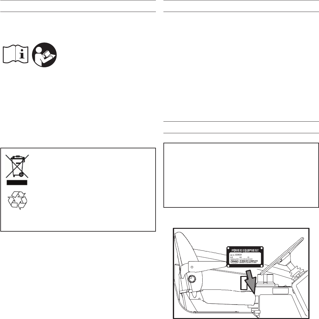
PROTECT THE ENVIRONMENT
Please dispose of packaging materials
and used machine components such as
batteries in an environmentally safe way
according to your local waste disposal
regulations.
Always remember to recycle.
Tennant Company
PO Box 1452
Minneapolis, MN 55440
Phone: (800) 553- 8033
www.tennantco.com
PerformanceView, Pro−ID, Pro−Check, Zone Settings, Thermo−
Sentry, Touch−N−Go, 1−STEP, Clean−Wedge, Variable Drain
Valve, EasyOpen, Grip−n−Go, MaxPro, Dura−Track, SmartRelease,
InstantAccess, Duramer, FaST−PAK, ErgoSpace, and Lower Total
Cost of Ownership are trademarks of Tennant Company.
Specications and parts are subject to change without notice.
Original Instructions. Copyright © 2017 Tennant Company. All rights
reserved.
INTENDED USE
The T20 is an industrial rider machine designed to
scrub hard surfaces (concrete, asphalt, stone, synthetic,
etc). Typical applications include industrial warehouses,
manufacturing facilities, distribution facilities, stadiums,
arenas, convention centers, parking facilities, trans-
portation terminals, and construction sites. Do not use
this machine on soil, grass, artificial turf, or carpeted
surfaces. Do not use where excessive debris is present
such as leaves, paper, etc. This machine can be used
both indoors and outdoors, but ensure there is ad-
equate ventilation if used indoors. This machine is not
intended for use on public roadways. Do not use this
machine other than described in this Manual.
MACHINE DATA
Please ll out at time of installation for future reference.
Model No. - _________________________________________
Serial No. - _________________________________________
Installation Date - ____________________________________
SERIAL NUMBER LOCATION

3
T20 Service Information (5-2017)
CONTENTS
CONTENTS
INTRODUCTION ...................................................2
INTENDED USE ....................................................2
MACHINE DATA ....................................................2
SERIAL NUMBER LOCATION ........................2
CONTENTS ...........................................................3
SAFETY PRECAUTIONS ......................................6
GENERAL INFORMATION ..................................10
ELECTRICAL COMPONENT LOCATOR ......10
HYDRAULIC COMPONENT LOCATOR .......19
SPECIFICATIONS ........................................27
MAINTENANCE ..................................................31
MAINTENANCE CHART ...............................32
YELLOW TOUCH POINTS ...........................35
LUBRICATION ..............................................35
ENGINE OIL .............................................35
SQUEEGEE CASTER BEARING ............35
FRONT WHEEL SUPPORT BEARING ....35
STEERING CYLINDER BEARING ........35
REAR WHEEL BEARINGS ......................36
TORQUE TUBES−CYLINDRICAL
BRUSHES ...........................................36
TORQUE TUBES−DISK BRUSHES ........36
PIVOT SHAFT−DISK BRUSHES .............36
HYDRAULICS ..............................................37
HYDRAULIC FLUID . ...............................38
HYDRAULIC HOSES ..............................38
ENGINE - GAS/LPG .....................................39
COOLING SYSTEM ................................39
AIR FILTER .............................................40
FUEL FILTER (LPG) ................................40
LPG VAPORIZER ....................................40
FUEL FILTER (GASOLINE) .....................40
ENGINE BELT .........................................41
PCV SYSTEM .........................................41
SPARK PLUGS −
MITSUBISHI ENGINES ......................41
CAMSHAFT AND BALANCE SHAFT
BELTS −MITSUBISHI ENGINES .......41
ENGINE - DIESEL ........................................42
COOLING SYSTEM ................................42
AIR FILTER .............................................43
FUEL FILTER ...........................................43
FUEL LINES .............................................43
PRIMING THE FUEL SYSTEM ................44
ENGINE BELT .........................................44
BATTERY .....................................................44
FUSES AND RELAYS ...................................45
RELAY PANEL FUSES AND RELAYS .....45
ENGINE HARNESS FUSES
AND RELAYS .....................................46
OPTIONAL RELAYS ...............................46
CIRCUIT BREAKERS (EC−H2O) ............46
SCRUB BRUSHES AND PADS ...................46
DISK BRUSHES ...........................................46
REPLACING DISK BRUSHES OR PAD
DRIVER ..............................................47
REPLACING DISK PADS .......................47
CHECKING THE DISK SCRUB HEAD
STOP BUMPERS ...............................48
CYLINDRICAL BRUSHES ............................49
REPLACING OR ROTATING
CYLINDRICAL BRUSHES ..................49
CHECKING CYLINDRICAL
BRUSH PATTERN ..............................50
ADJUSTING THE CYLINDRICAL
BRUSH TAPER ..................................51
ADJUSTING THE CYLINDRICAL
BRUSH WIDTH ...................................51
SIDE BRUSH (OPTION) ..............................52
REPLACING THE SIDE BRUSH .............52
FAST SYSTEM .............................................53
REPLACING THE FAST−PAK CARTON .53
CLEANING THE FAST SUPPLY HOSE
CONNECTOR .....................................54
CLEANING THE FAST SYSTEM FILTER
SCREEN .............................................54
REPLACING THE FAST SYSTEM .....................
FILTERS ..............................................54
EC−H2O MODULE FLUSH
PROCEDURE .........................................55
CLEANING THE EC−H2O
FILTER SCREEN ...................................56
SQUEEGEE BLADES ...................................57
REPLACING (OR ROTATING) THE REAR
SQUEEGEE BLADES ........................57
REPLACING OR ROTATING THE SIDE
SQUEEGEE BLADES .........................59
REPLACING OR ADJUSTING THE SIDE
BRUSH SQUEEGEE BLADE
(OPTION) ............................................61
LEVELING THE REAR SQUEEGEE .......62
ADJUSTING THE REAR SQUEEGEE
BLADE DEFLECTION .........................63
SKIRTS AND SEALS ....................................64

4T20 Service Information (5-2017)
CONTENTS
SCRUB HEAD SKIRT ..............................64
RECOVERY TANK SEAL ........................64
SOLUTION TANK SEALS .......................64
BRAKES AND TIRES....................................65
BRAKES ...................................................65
TIRES .......................................................65
FRONT WHEEL ......................................65
PROPELLING MOTOR .................................65
PUSHING, TOWING, AND TRANSPORTING
THE MACHINE .......................................66
PUSHING OR TOWING THE
MACHINE ............................................66
TRANSPORTING THE MACHINE ...........66
MACHINE JACKING .....................................68
STORAGE INFORMATION ...........................68
FREEZE PROTECTION (MACHINES
WITHOUT EC−H2O SYSTEM) ..........69
FREEZE PROTECTION (MACHINES
WITH EC−H2O SYSTEM) ..................69
PRIMING THE EC−H2O SYSTEM ..........71
ELECTRICAL TROUBLESHOOTING .................72
SCHEMATIC SYMBOLS ...............................73
MACHINE ELECTRICAL SCHEMATIC ........74
DIESEL ENGINE HARNESS ELECTRICAL
SCHEMATIC ...........................................81
GAS ENGINE HARNESS ELECTRICAL
SCHEMATIC ...........................................82
LPG ENGINE HARNESS ELECTRICAL
SCHEMATIC ...........................................84
T20 OPTION COMPONENTS ......................87
KEY SWITCH ................................................88
MAIN BRUSHES ON ....................................91
SCRUB VACUUM ON AND
SQUEEGEE DOWN ...............................92
SIDE BRUSH ON ..........................................93
TANK LEVEL SWITCHES .............................94
AUTO-FILL SOLENOID ................................95
CONVENTIONAL DETERGENT PUMP
AND ES PUMP .......................................96
HORN ...........................................................97
REVERSE PROPEL .....................................98
SHUTDOWN RELAY ....................................99
STARTING SYSTEM ON ............................103
GLOW PLUGS ON .....................................105
CONVENTIONAL MAIN AND SIDE BRUSH
SOLUTION VALVES .............................106
FAST SYSTEM ON .....................................107
FUEL LEVEL SENSORS ............................108
IMPACT, HYDRAULIC TEMP AND FILTER
SENSOR ..............................................109
OIL PRESSURE, TEMPERATURE, AND MIL
SYSTEM ............................................... 110
FUEL PUMP AND ENGINE SPEED
CONTROL ............................................112
KEY ON POWER DISTRIBUTION..............115
KEY OFF POWER DISTRIBUTION ............ 116
HORN .........................................................117
ENABLE/DISABLE CHART ........................118
CONTROL BOARD CONNECTORS (P1) ..119
CONTROL BOARD CONNECTORS (P2) ..120
FAULT INDICATORS ..................................121
CONDITION AND WARNING
INDICATORS ........................................122
HYDRAULIC TROUBLE SHOOTING ................123
HYDRAULIC SCHEMATIC SYMBOLS .......124
HYDRAULIC SCHEMATIC .........................126
OPERATING MATRIX .................................128
OPTION COMPONENTS ...........................129
HOSE GROUP: STEERING AND
PROPEL ...............................................130
HOSE GROUP: PUMP AND VAC FAN .......131
HOSE GROUP: CYLINDRICAL BRUSH ....132
HOSE GROUP: DISK BRUSH ....................133
HOSE GROUP: SQUEEGEE LIFT .............134
SCRUB HEAD LOWER ..............................135
SCRUB HEAD LIFT ....................................136
SQUEEGEE LOWER ..................................137
SQUEEGEE LIFT........................................138
MAIN BRUSH ON (CYLINDRICAL) ............139
MAIN BRUSH ON (DISK) ...........................140
SIDE BRUSH ON ........................................141
SCRUB VACUUM FAN ON .........................142
SCRUB VACUUM FAN AND
SIDE BRUSH ON .................................143
SIDE BRUSH LOWER ................................144
SIDE BRUSH LIFT ......................................145
SIDE BRUSH EXTEND ..............................146
SIDE BRUSH RETRACT ............................147
HYDRAULIC SOLENOID VALVE
DETAILS ...............................................148
SERVICE ...........................................................149
PRO-PANEL SERVICE MODES .................149
SERVICE MODE ....................................149
MANUAL MODE.....................................150
CONFIGURATION MODE .....................151
SELF TEST MODE ................................152
INPUT DISPLAY MODE .........................153
THROTTLE ADJUST MODE ..................154

5
T20 Service Information (5-2017)
CONTENTS
DOWN PRESSURE ADJUST MODE ....155
MEMBRANE TEST MODE.....................157
MEMBRANE PANEL SERVICE MODES ....158
SERVICE MODE ....................................158
MANUAL MODE.....................................159
CONFIGURATION MODE .....................160
SELF TEST MODE ................................161
INPUT DISPLAY MODE .........................163
THROTTLE ADJUST MODE ..................164
DOWN PRESSURE ADJUST MODE ....165
MEMBRANE TEST MODE.....................167
FRONT TIRE AND WHEEL SUPPORT ......168
REPLACE FRONT DRIVE WHEEL .......168
6T20 Service Information (5-2017)
SAFETY PRECAUTIONS
SAFETY PRECAUTIONS
SAFETY PRECAUTIONS
T20 Gas/LPG 9016200 (08−2016)
4
IMPORTANT SAFETY INSTRUCTIONS − SAVE THESE INSTRUCTIONS
The following precautions are used throughout
this manual as indicated in their description:
WARNING: To warn of hazards or
unsafe practices that could result in
severe personal injury or death.
CAUTION: To warn of unsafe practices
that could result in minor or moderate
personal injury.
FOR SAFETY: To identify actions that must be
followed for safe operation of equipment.
The following information signals potentially
dangerous conditions to the operator. Know when
these conditions can exist. Locate all safety
devices on the machine. Report machine
damage or faulty operation immediately.
WARNING: Flammable materials can
cause an explosion or fire. Do not use
flammable materials in tank.
WARNING: Flammable materials or
reactive metals can cause an explosion
or fire. Do not pickup.
WARNING: Moving belt and fan. Keep
away.
WARNING: Engine emits toxic gases.
Serious injury or death can result.
Provide adequate ventilation.
WARNING: Burn hazard. Hot surface. Do
NOT touch.
CAUTION: LPG engine will run for a
few seconds after key is turned off.
Apply parking brake before leaving
machine.
WARNING: Do not spray people or
animals. Severe personal injury can
result. Wear eye protection. Hold
sprayer with two hands.
WARNING: This machine contains
chemicals known to the State of
California to cause cancer, birth defects,
or other reproductive harm.
This machine may be equipped with
technology that automatically communicates
over the cellular network. If this machine will
be operated where cell phone use is restricted
because of concerns related to equipment
interference, please contact a Tennant
representative for information on how to
disable the cellular communication
functionality.
FOR SAFETY:
1. Do not operate machine:
−Unless trained and authorized.
−Unless operator manual is read and
understood.
−Under the influence of alcohol or
drugs.
−While using a cell phone or other
types of electronic devices.
−In dusty environments without the
vacuum fan on.
−Without filters in place or with clogged
filters.
−Unless mentally and physically
capable of following machine
instructions.
−If it is not in proper operating
condition.
−With pads or accessories not supplied
or approved by Tennant. The use of
other pads may impair safety.
−In areas where flammable
vapors/liquids or combustible dusts
are present.
−In areas that are too dark to safely see
the controls or operate the machine
unless operating / headlights are
turned on.
−In areas with possible falling objects
unless equipped with overhead guard.
2. Before starting machine:
−Check for fuel, oil, and liquid leaks.
−Keep sparks and open flame away
from refueling area.
−Make sure all safety devices are in
place and operate properly.
−Check brakes and steering for proper
operation.
−Adjust seat and fasten seat belt.
3. When starting machine:
−Keep foot on brake and directional
pedal in neutral.
Home
Find...
Go To..

SAFETY PRECAUTIONS
7
T20 Service Information (5-2017)
SAFETY PRECAUTIONS
5
T20 Gas/LPG 9016200 (08−2016)
4. When using machine:
−Use only as described in this manual.
−Use brakes to stop machine.
−Do not pick up burning or smoking
debris, such as cigarettes, matches or
hot ashes
−Go slowly on inclines and slippery
surfaces.
−Do not scrub on ramp inclines that
exceed 10% grade or transport
(GVWR) on ramp inclines that exceed
14% grade.
−Reduce speed when turning.
−Keep all parts of body inside operator
station while machine is moving.
−Always be aware of surroundings
while operating machine.
−Do not access the video / help screens
while the machine is moving.
(Pro−Panel).
−Use care when reversing machine.
−Keep children and unauthorized
persons away from machine.
−Do not carry passengers on machine.
−Always follow safety and traffic rules.
−Report machine damage or faulty
operation immediately.
−Follow mixing, handling and disposal
instructions on chemical containers.
−Follow safety guidlines concerning
wet floors.
5. Before leaving or servicing machine:
−Do not park near combustible
materials, dusts, gases, or liquids.
−Stop on level surface.
−Set parking brake.
−Turn off machine and remove key.
6. When servicing machine:
−All work must be done with sufficient
lighting and visibility.
−Keep work area well ventilated.
−Avoid moving parts. Do not wear loose
clothing, jewelry and secure long hair.
−Block machine tires before jacking
machine up.
−Jack machine up at designated
locations only. Support machine with
jack stands.
−Use hoist or jack that will support the
weight of the machine.
−Do not push or tow the machine
without an operator in the seat
controlling the machine.
−Do not power spray or hose off
machine near electrical components.
−Disconnect battery connections before
working on machine.
−Avoid contact with battery acid.
−Avoid contact with hot engine coolant.
−Do not remove cap from radiator when
engine is hot.
−Allow engine to cool.
−Keep flames and sparks away from
fuel system service area. Keep area
well ventilated.
−Use cardboard to locate leaking
hydraulic fluid under pressure.
−All repairs must be performed by a
trained service mechanic.
−Do not modify the machine from its
original design.
−Use Tennant supplied or approved
replacement parts.
−Wear personal protective equipment
as needed and where recommended in
this manual.
For Safety: wear hearing protection.
For Safety: wear protective gloves.
For Safety: wear eye protection.
For Safety: wear protective dust mask.
7. When loading/unloading machine
onto/off truck or trailer:
−Drain tanks before loading machine.
−Lower scrub head and squeegee
before tying down machine.
−Turn off machine and remove key.
−Use ramp, truck or trailer that will
support the weight of the machine and
operator.
−Do not load/unload on ramp inclines
that exceed 18% grade.
−Use winch. Do not drive the machine
onto/off the truck or trailer unless the
load height is 380 mm (15 in) or less
from the ground.
−Set parking brake after machine is
loaded.
−Block machine tires.
−Tie machine down to truck or trailer.
Home
Find...
Go To..
8T20 Service Information (5-2017)
SAFETY PRECAUTIONS
SAFETY PRECAUTIONS
T20 Gas/LPG 9016200 (08−2016)
6
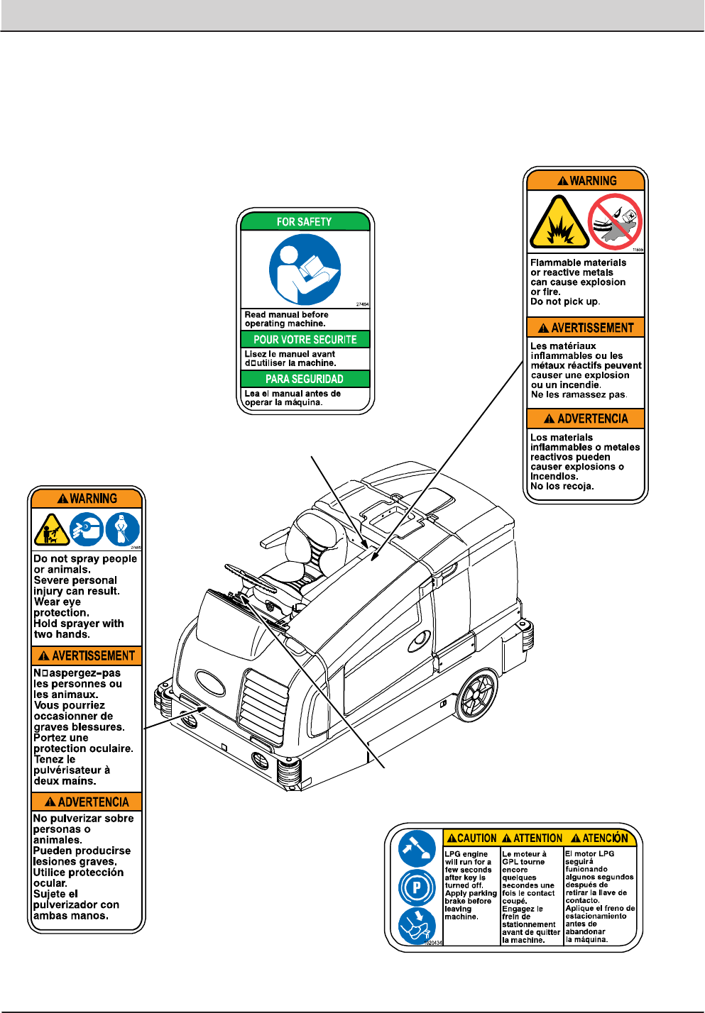
The following safety labels are mounted on the
machine in the locations indicated. If these or any
labels become damaged or illegible, install a new
label in its place.
Located on the side
of the operator
compartment.
Located on the side of the
operator compartment.
Located next to the ignition switch on the
instrument panel. (LPG machines only)
Located on frame of
machine.
WARNING LABEL −
Flammable materials or
reactive metals can cause
explosion or fire. Do not
pick up.
WARNING LABEL − Do
not spray people or
animals. Severe personal
injury can result. Wear
eye protection. Hold
sprayer with both hands.
FOR SAFETY LABEL −
Read manual before
operating machine
CAUTION LABEL − LPG engine will run for
a few seconds after key is turned off. Apply
parking brake before leaving machine.
Home
Find...
Go To..
SAFETY PRECAUTIONS
9
T20 Service Information (5-2017)
SAFETY PRECAUTIONS
7
T20 Gas/LPG 9016200 (08−2016)
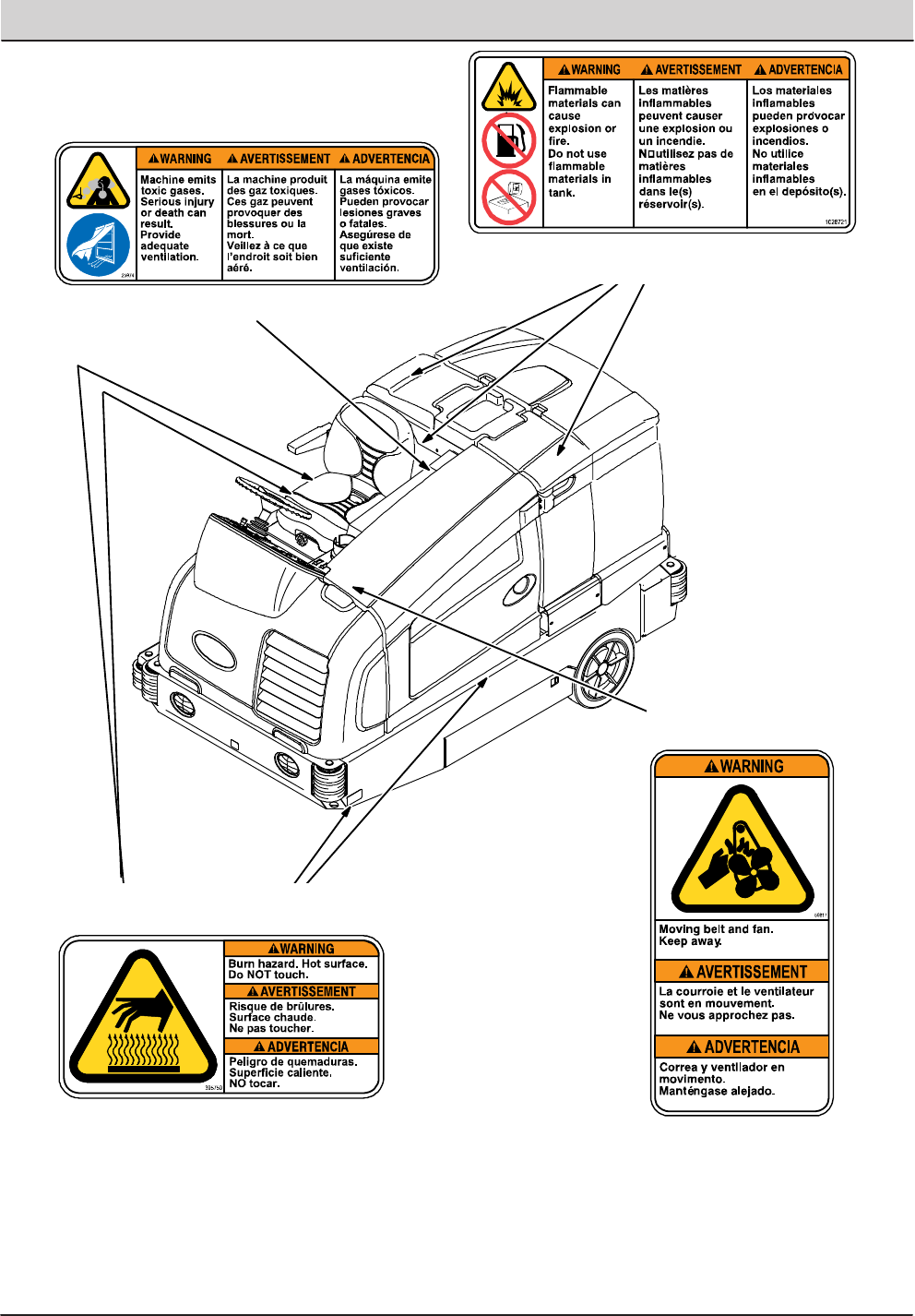
Located on the side of the bumper, on the
exhaust shield, on the hydraulic reservoir, and
on the scrub head (disk head machines only).
Located on engine
compartment panel.
Located on the side of the operator
compartment.
WARNING LABEL − Machine emits toxic
gases. Serious injury or death can result.
Provide adequate ventilation.
WARNING LABEL − Flammable materials can
cause explosion or fire. Do not use flammable
materials in tank.
Located next to the solution tank covers
and on the detergent tank.
WARNING LABEL − Burn hazard. Hot
surface. Do NOT touch
WARNING LABEL −
Moving belt and fan.
Keep away.
Home
Find...
Go To..
10 T20 Service Information (5-2017)
GENERAL INFORMATION
GENERAL INFORMATION
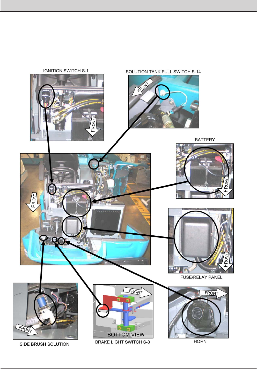
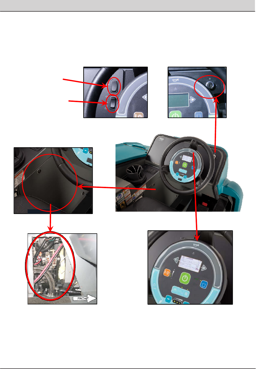
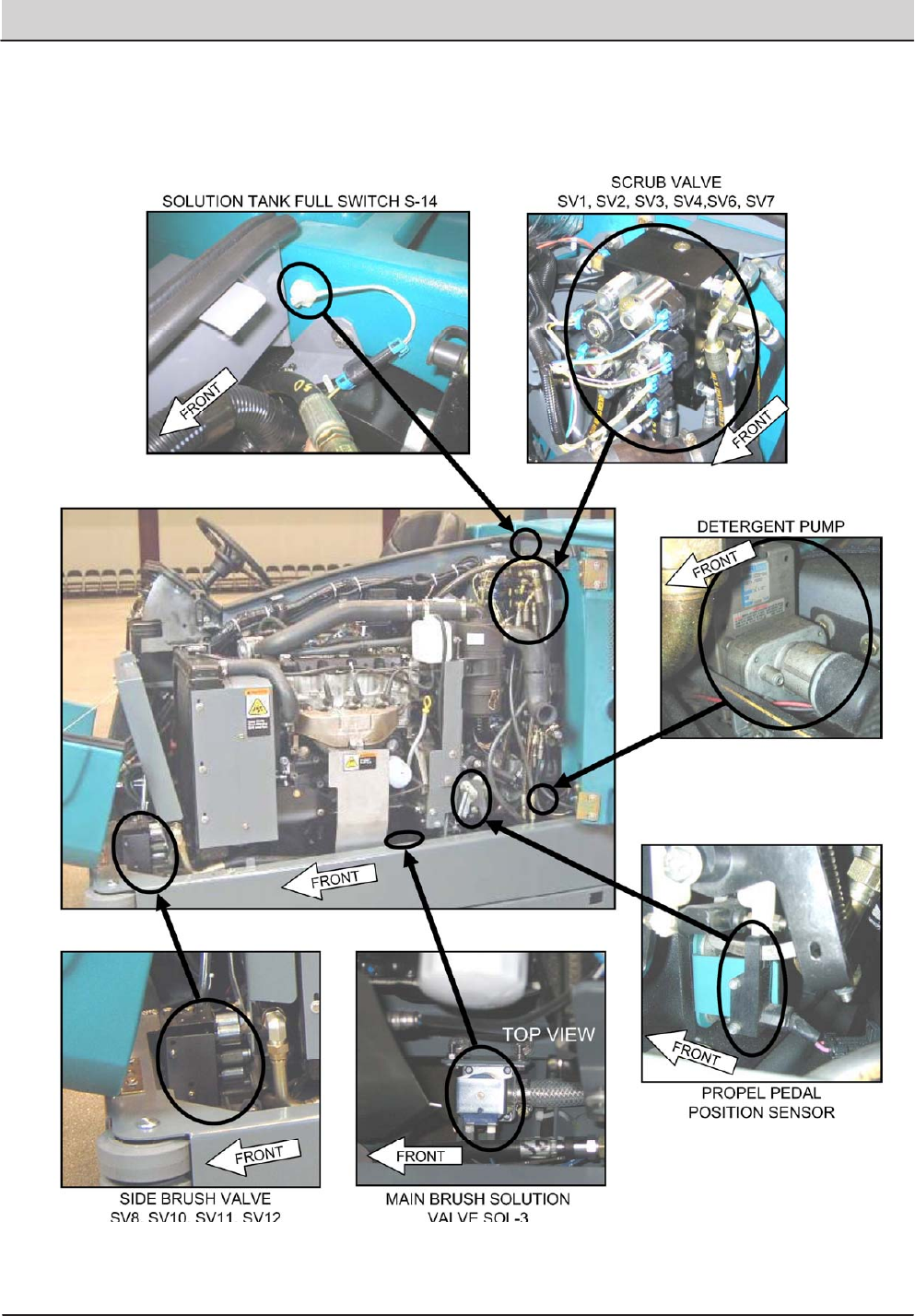
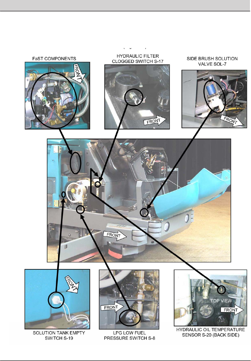
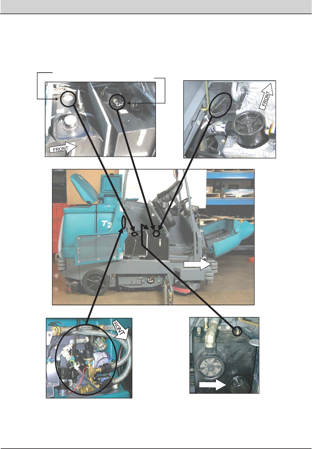
ELECTRICAL COMPONENT LOCATOR
T20 Electrical Component Locator
Page 1 of 10
VALVESOL‐7
T20 Service Information (5-2017) 11
GENERAL INFORMATION
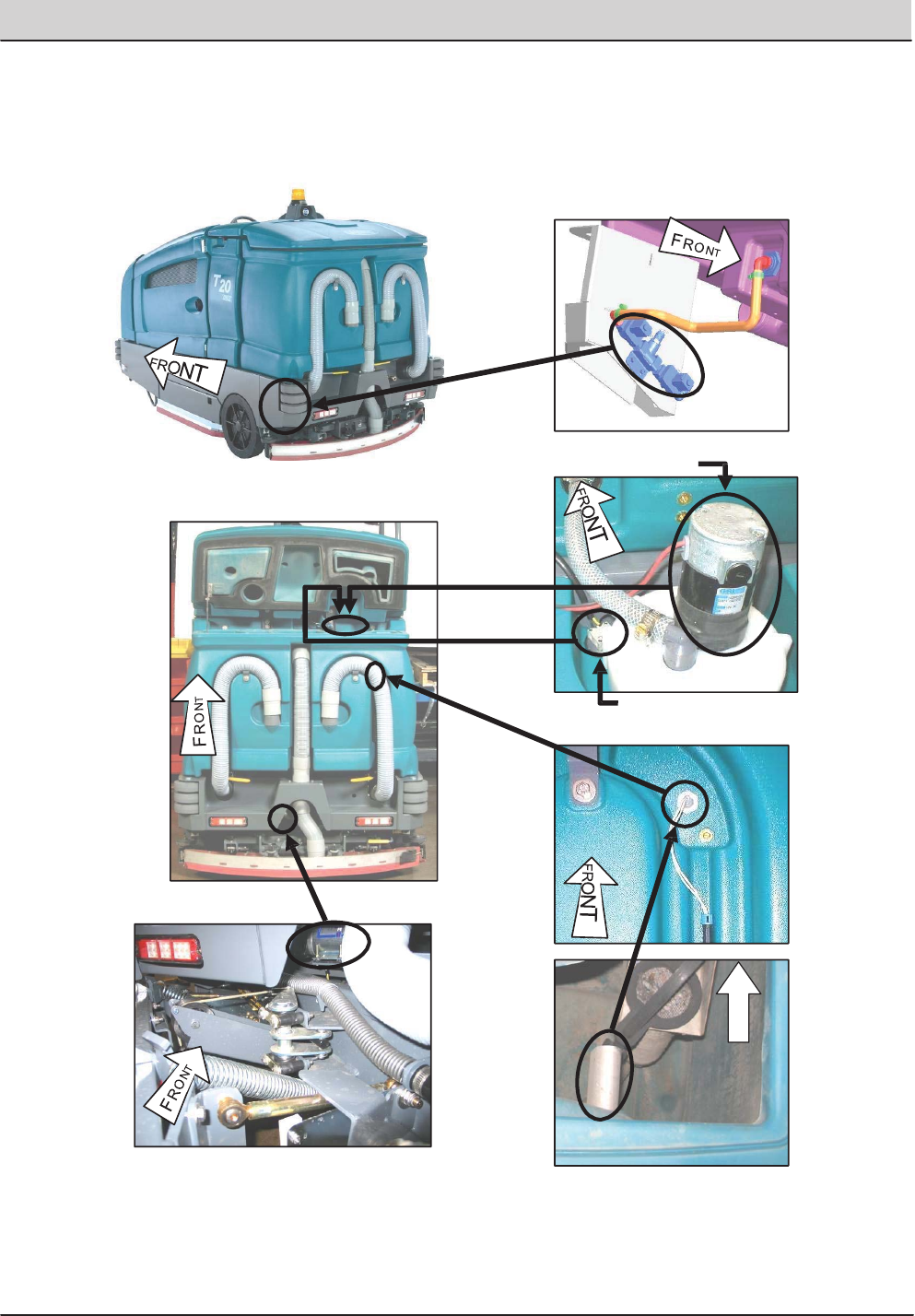
T20 Electrical Component Locator
Page 2 of 10
HORNSWITCHS‐22
IGNITIONSWITCHS‐1
LIGHTSWITCHS‐4
SPRAYNOZZLE
SWITCHS‐25
ACCESSPANELFOR
RIGHTSIDEofENGINE
ACCESSPANELREMOVED
12 T20 Service Information (5-2017)
GENERAL INFORMATION
T20 Electrical Component Locator
Page 3 of 10
T20 Service Information (5-2017) 13
GENERAL INFORMATION
T20 Electrical Component Locator
Page 4 of 10
14 T20 Service Information (5-2017)
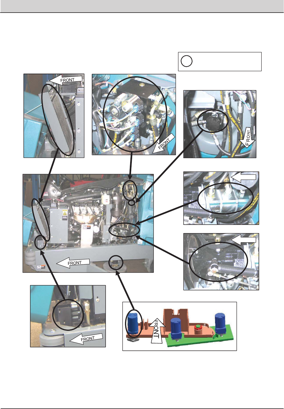
GENERAL INFORMATION
FaST COMPONENTS
GAS/DIESEL FUEL LEVEL SENDER S-7
HYDRAULIC FILTER CLOGGED SWITCH S-17
HYDRAULIC OIL TEMPERATURE
SENSOR S-20 (BACK SIDE)
FRONT
TOP VIEW
FRONT
GAS/LPG ENGINE
DIAGNOSTIC CONNECTOR
T20 Electrical Component Locator
Page 5 of 10
T20 Service Information (5-2017) 15
GENERAL INFORMATION
AUTO FILL SOLENOID VALVES
FRONT
SOL-1
ES PUMP
INNER VIEW
SOL-2
TOP VIEW
INSIDE TANK
SPRAY NOZZLE/WAND PUMP
RECOVERY TANK FULL SWITCH S-15
RECOVERY TANK HALF
FULL SWITCH S-16
OUTSIDE TANK
T20 Electrical Component Locator
Page 6 of 10
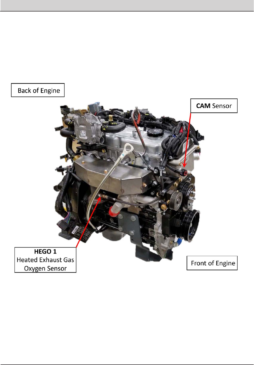
16 T20 Service Information (5-2017)
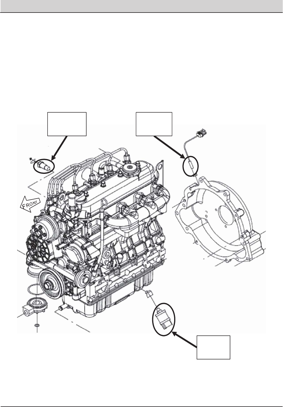
GENERAL INFORMATION
Crankshaft
Position
Sensor
Coolant
Temperature
Sensor
Oil
Pressure
Switch
Diesel Engine
T20 Electrical Component Locator
Page 7 of 10
T20 Service Information (5-2017) 17
GENERAL INFORMATION
T20 Electrical Component Locator
Page 9 of 10
GAS/LPG
18 T20 Service Information (5-2017)
GENERAL INFORMATION
T20 Electrical Component Locator
Page 10 of 10
GAS/LPG
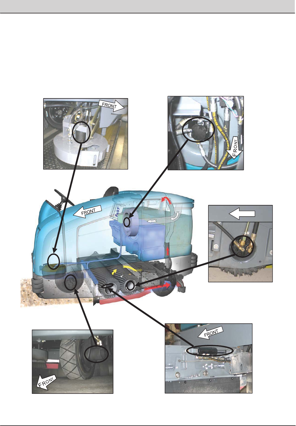
T20 Service Information (5-2017) 19
GENERAL INFORMATION
HYDRAULIC COMPONENT LOCATOR
VACUUM FAN MOTOR
CYLINDRICAL MAIN BRUSH
MOTOR (REAR)
FRONT
SIDE BRUSH MOTOR
LEFT SIDE SQUEEGEE LIFT CYLINDER
PROPEL MOTOR
T20 Hydraulic Component Locator
Page 1 of 8
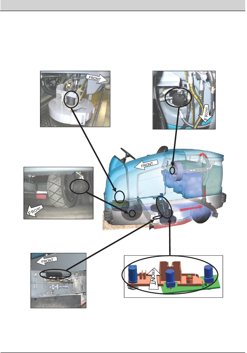
20 T20 Service Information (5-2017)
GENERAL INFORMATION
DISK MAIN BRUSH MOTORS
LEFT SIDE SQUEEGEE LIFT CYLINDER
VACUUM FAN MOTOR
SIDE BRUSH MOTOR
PROPEL MOTOR
T20 Hydraulic Component Locator
Page 2 of 8
T20 Service Information (5-2017) 21
GENERAL INFORMATION
HYDRAULIC OIL FILTER HYDRAULIC OIL RESERVOIR
FRONT
RIGHT SIDE SQUEEGEE LIFT CYLINDER
CYLINDRICAL MAIN BRUSH
MOTOR (FRONT)
STEERING VALVE
T20 Hydraulic Component Locator
Page 3 of 8
22 T20 Service Information (5-2017)
GENERAL INFORMATION
SCRUB MANIFOLD
SV1, SV2, SV3, SV4,SV6, SV7
RV1, RV2, CV1, PC1, PC2
VACUUM FAN MOTOR
HYDRAULIC OIL HEAT
EXCHANGER
DISK MAIN BRUSH MOTORS
FRONT
PROPEL PUMP
ACCESSORY PUMPS
FRONT
SIDE BRUSH MANIFOLD
SV8, SV10, SV11, SV12, PR1, PC8
See pages 16 and 17 for more
i
information on the Scrub and
Side Brush manifolds
T20 Hydraulic Component Locator
Page 4 of 8
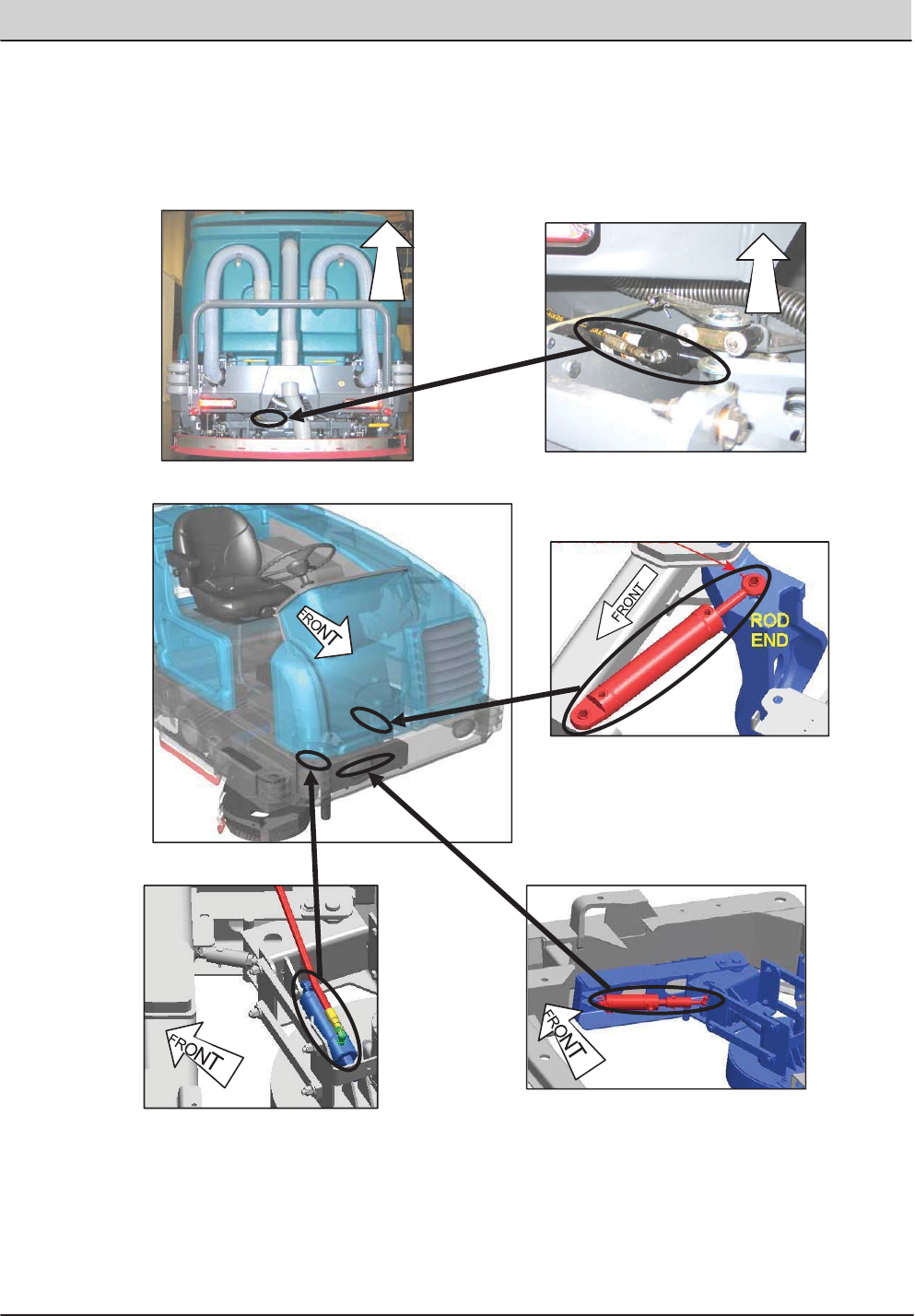
T20 Service Information (5-2017) 23
GENERAL INFORMATION
STEERING CYLINDER
FRONT BUMPER
(INNER VIEW)
F
R
ONT
SIDE BRUSH EXTEND CYLINDER
SIDE BRUSH LIFT CYLINDER
F
R
ONT
MAIN SQUEEGEE LIFT CYLINDER
T20 Hydraulic Component Locator
Page 5 of 8
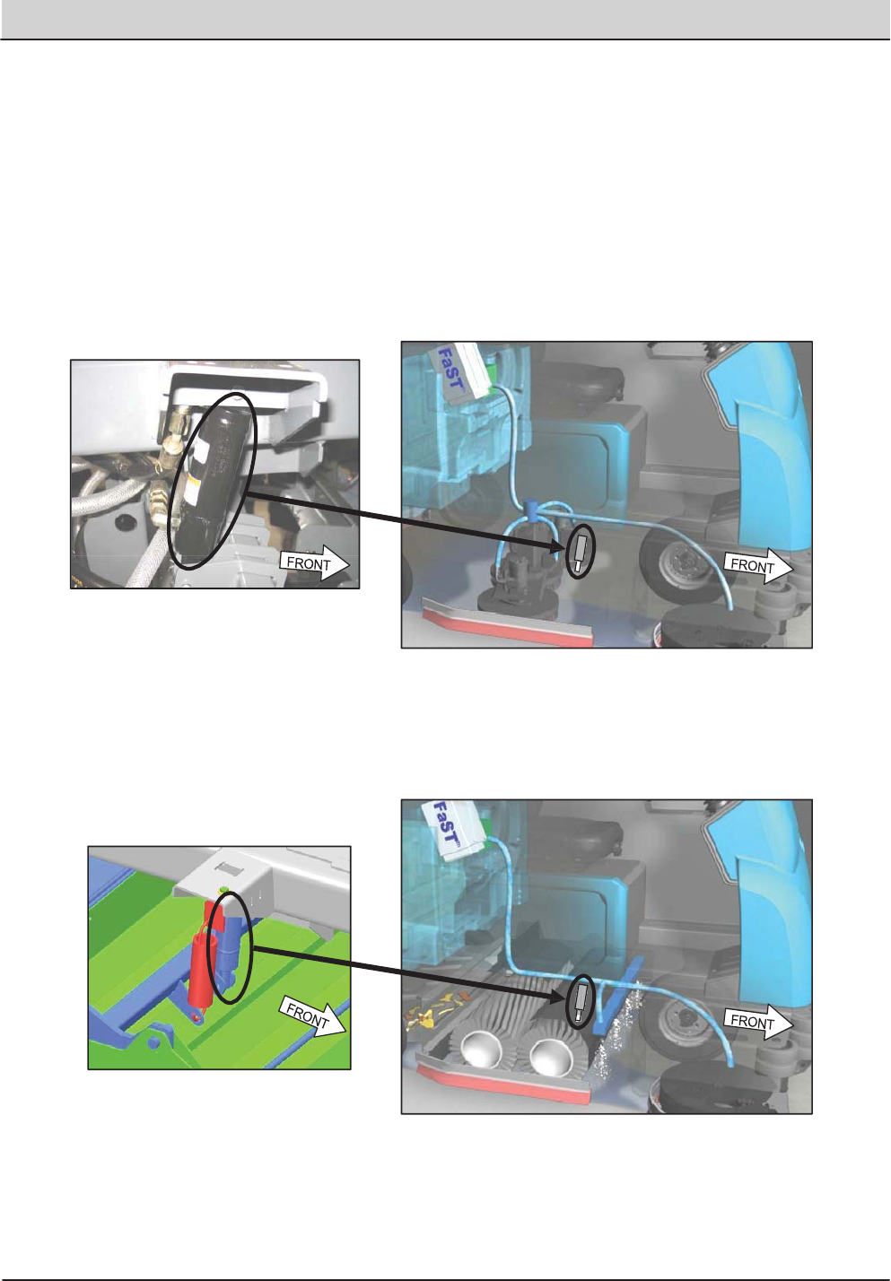
24 T20 Service Information (5-2017)
GENERAL INFORMATION
CYLINDRICAL SCRUB HEAD
LIFT CYLINDER
DISK SCRUB HEAD
LIFT CYLINDER
T20 Hydraulic Component Locator
Page 6 of 8
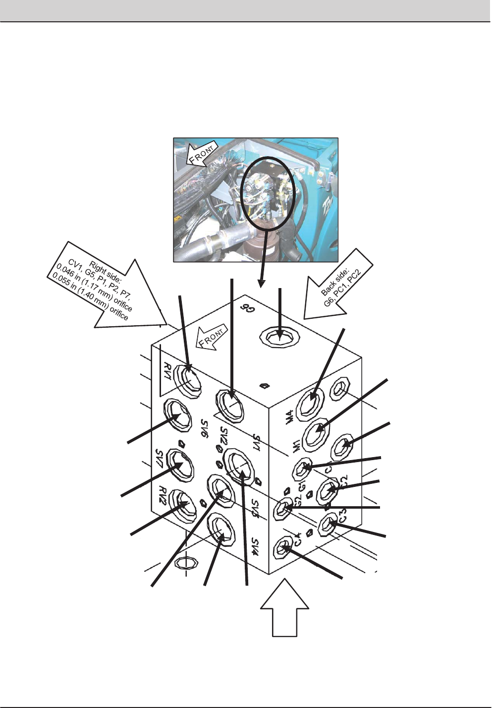
T20 Service Information (5-2017) 25
GENERAL INFORMATION
SCRUB MANIFOLD DETAILS
G6
M4
M1
C1
SV6
G1
C2
SV7
SV3
RV2
RV1
SV1
SV4 SV2
C4
C3
G2
Bottom:
T1, T2
T20 Hydraulic Component Locator
Page 7 of 8
26 T20 Service Information (5-2017)
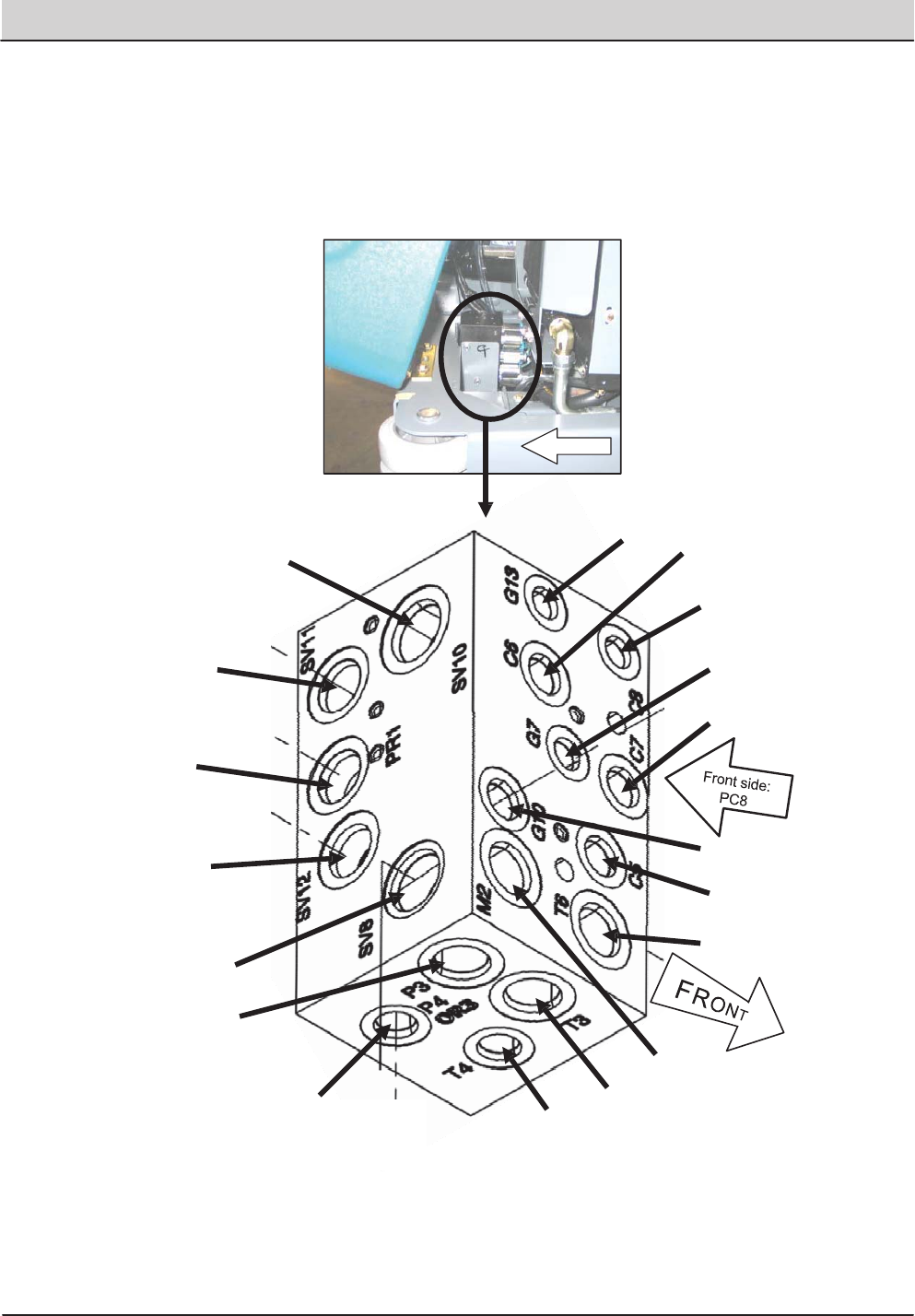
GENERAL INFORMATION
SIDE BRUSH MANIFOLD DETAILS
FRONT
C5
T6
SV8
P3
M2
C7
PR1
G7
G13
C8
C6
SV12
P4 &
OR3 0.040 in
(1.02 mm) orifice
T4
G10
T3
SV11
SV10
T20 Hydraulic Component Locator
Page 8 of 8
T20 Service Information (5-2017) 27
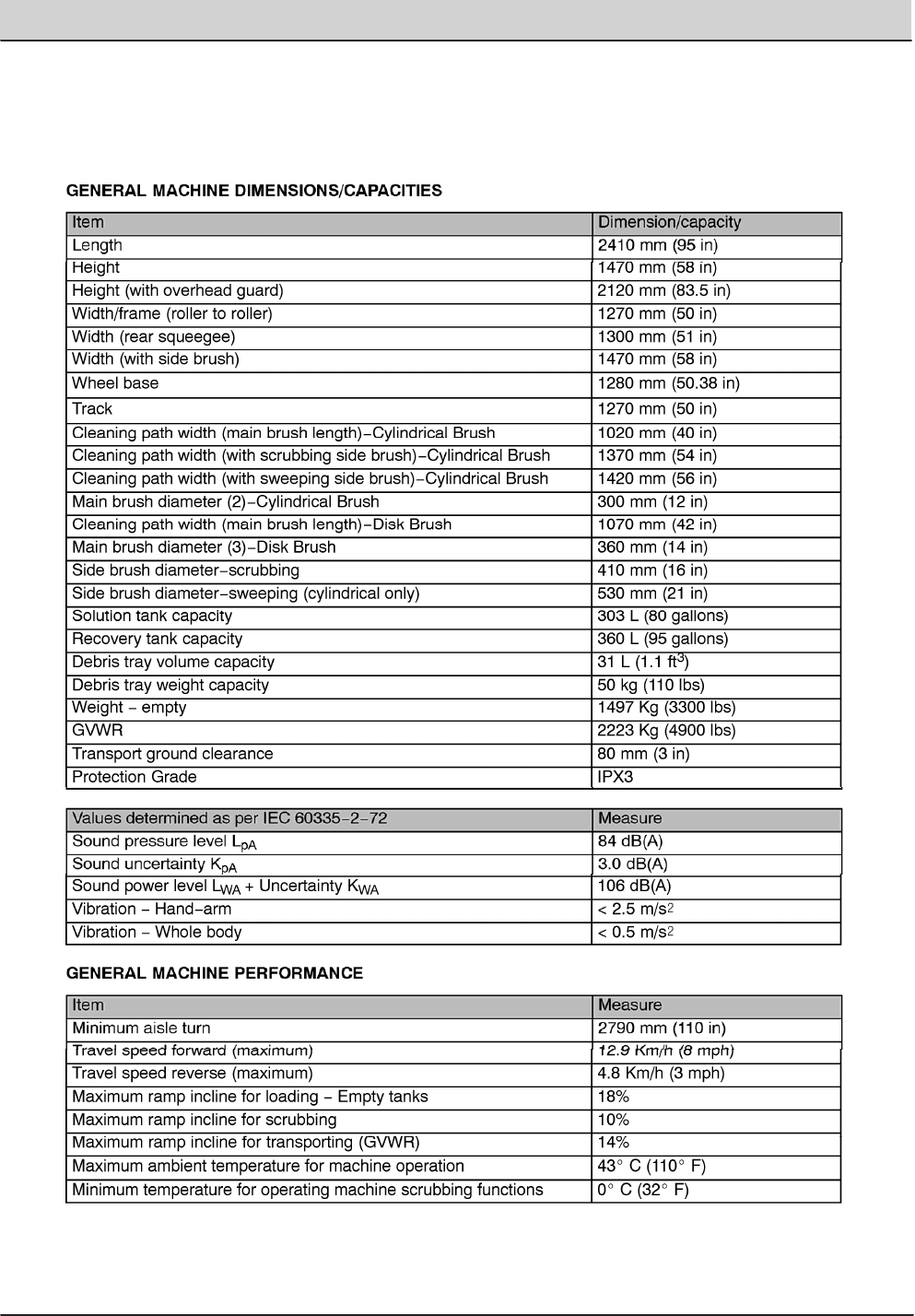
GENERAL INFORMATION
T20 Specifications
Page 1 of 4
SPECIFICATIONS
28 T20 Service Information (5-2017)
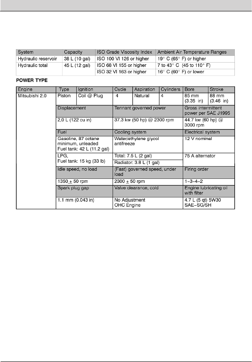
GENERAL INFORMATION
T20 Specifications
Page 2 of 4
T20 Service Information (5-2017) 29
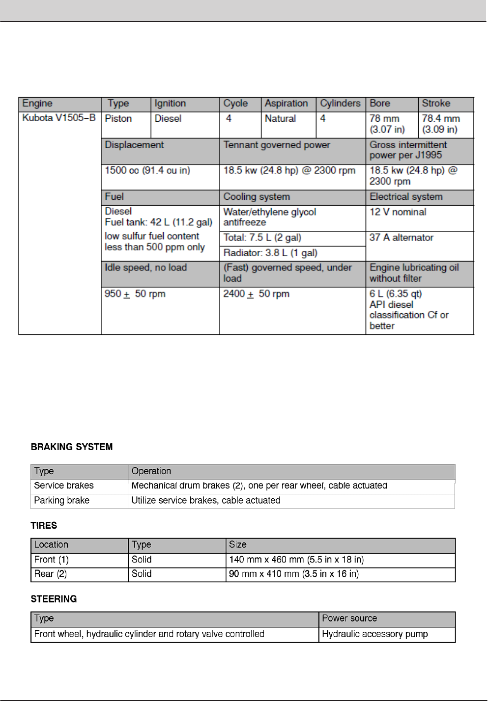
GENERAL INFORMATION
T20 Specifications
Page 3 of 4

30 T20 Service Information (5-2017)
GENERAL INFORMATION
T20 Specifications
Page 4 of 4
T20 Service Information (5-2017) 31
MAINTENANCE
MAINTENANCE
MAINTENANCE
MAINTENANCE
1
2
3
4
5
6
7
89
19
10
12
14
13
15
16
11
17
18
7
20
20
32 T20 Service Information (5-2017)
MAINTENANCE
MAINTENANCE CHART
The table below indicates the Person Responsible for each procedure.
O = Operator
T = Trained Personnel
Interval Person
Resp.
Key Description Procedure Lubricant/
Fluid
No. of
Service
Points
Daily O 1 Engine Check oil level EO 1
Check coolant level in reservoir WG 1
O 10 Hydraulic uid reservoir Check uid level HYDO 1
O 8, 9 Tank cover seals Check for damage or wear - 3
O 3, 14 Main brushes (Cylindrical) Check for damage and wear - 2
O 3, 14 Main brushes or pads (Disk) Check for damage and wear - 3
O 4 Side brush (option) Check for damage and wear - 1
Check squeegee blade for
damage and wear
- 1
O 6 Rear squeegee blade Check for damage and wear - 1
Check deection - 1
O 7 Side squeegee blades Check for damage and wear - 2
O 8 Recovery tank Clean - 1
O 8 Recovery tank, ES mode (option) Clean ES lter - 1
O 9 Solution tank, ES mode (option) Clean - 1
O 5 Debris tray Clean debris tray, screen,
and hose
- 1
50
Hours
O 16 FaST/ec-H2O lter screen (Op-
tion)
Clean - 1
O 3, 14 Main brushes (Cylindrical) Rotate front to rear - 2
T 3, 14 Main brushes or pads (Disk) Check brush pattern and
adjust if needed
- 2
T 13 Front wheel Torque wheel nuts
(after initial 50 hours only)
- 1
T 1 Fuel Lines (Diesel machines) Check for damage and wear
and tighten loose clamp
bands
- 1
T 15 Battery Clean and tighten battery
cable connections
(after initial 50 hours only)
- 1
T 1 Engine Check belt tension - 1
LUBRICANT/FLUID
EO . . . . Engine oil, 5W30 SAE−SG/SH only.
HYDO . TennantTrue premium hydraulic uid or equivalent
WG . . . Water and ethylene glycol anti-freeze, −34<?> C (−30<?> F)
SPL . . . Special lubricant, Lubriplate EMB grease (Tennant part number 01433−1)
NOTE: More frequent maintenance intervals may be required in extremely dusty conditions.
T20 Service Information (5-2017) 33
MAINTENANCE
Interval Person
Resp.
Key Description Procedure Lubricant/
Fluid
No. of
Service
Points
100
Hours
T 19 Radiator Clean core exterior - 1
T 19 Hydraulic cooler Clean core exterior - 1
T 1 Engine Change oil and lter EO 1
Drain LPG vaporizer oil
buildup
1
O 13, 20 Tires Check for damage - 3
T 6 Rear squeegee casters Lubricate SPL 2
T 6 Rear squeegee Check leveling - 1
O 2 Scrub head skirt Check for damage or wear - 1
T 3, 14 Disk scrub head stop bumper Check for damage or wear 2
200
Hours
T 12 Front wheel support
bearings
Lubricate SPL 2
T17, 18 Torque tube (Cylindrical
brushes)
Lubricate SPL 4
T 3, 14 Torque tube (Disk
brushes)
Lubricate SPL 4
T 3 Pivot shaft (Disk
brushes)
Lubricate SPL 4
T 12 Steering cylinder Lubricate SPL 1
T 1, 19 Radiator hoses and
clamps
Check for tightness and
wear
- 2
T11 Brake pedal Check adjustment - 1
400
Hours
T 1 Engine Replace air lter - 1
Replace fuel lter - 1
T 20 Rear wheel bearings Check, lubricate, and adjust SPL 2
800
Hours
T 10 Hydraulic reservoir Replace ller cap HYDO 1
T - Hydraulic hoses Check for wear and damage -ALL
T 1, 19 Cooling system Flush WG 2
T 13 Propelling motor Torque shaft nut - 1
T 13 Front wheel Torque wheel nuts - 1
T 15 Battery Clean and tighten battery
cable connections
- 1
1000
Hours
T 16 FaST system lters Replace - 2
T 1 Engine (Gas/LPG Machines) Replace spark plugs - 4
T 1 Engine (Gas/LPG Machines) Inspect PCV system - 1
T 1, 19 Radiator hoses Check for cracks or
deterioration
- 2
LUBRICANT/FLUID
EO . . . . Engine oil, 5W30 SAE−SG/SH only.
HYDO . TennantTrue premium hydraulic uid or equivalent
WG . . . Water and ethylene glycol anti-freeze, −34<?> C (−30<?> F)
SPL . . . Special lubricant, Lubriplate EMB grease (Tennant part number 01433−1)
NOTE: More frequent maintenance intervals may be required in extremely dusty conditions.

34 T20 Service Information (5-2017)
MAINTENANCE
Interval Person
Resp.
Key Description Procedure Lubricant/
Fluid
No. of
Service
Points
1200
Hours
T 10 Hydraulic uid lter Replace uid lter - 1
2400
Hours
T 10 Hydraulic uid reservoir Replace strainer outlet - 1
Change hydraulic uid HYDO 1
5000
hours
1 1 Engine (Gas/LPG Machines) Replace camshaft and
balance shaft belts
- 2
LUBRICANT/FLUID
EO . . . . Engine oil, 5W30 SAE−SG/SH only.
HYDO . TennantTrue premium hydraulic uid or equivalent
WG . . . Water and ethylene glycol anti-freeze, −34<?> C (−30<?> F)
SPL . . . Special lubricant, Lubriplate EMB grease (Tennant part number 01433−1)
NOTE: More frequent maintenance intervals may be required in extremely dusty conditions.
T20 Service Information (5-2017) 35
MAINTENANCE
MAINTENANCE
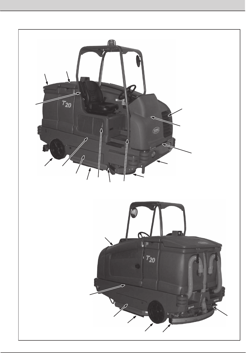
YELLOW TOUCH POINTS
This machine features easy to find yellow touch
points for simple service items. No tools are
required to perform these maintenance
operations.
LUBRICATION
FOR SAFETY: Before leaving or servicing
machine, stop on level surface, set parking
brake, turn off machine, and remove key.
ENGINE OIL
Check the engine oil level daily. Change the oil
and oil filter after every 100 hours of operation.
Fill the engine with oil until the oil is between the
indicator marks on the dipstick. DO NOT fill past
the top indicator mark.
The engine oil capacity for Mitsubishi engines
is 4.7 L (5 qt) with oil filter.
SQUEEGEE CASTER BEARINGS
Lubricate the squeegee caster bearings after
every 100 hours of operation.
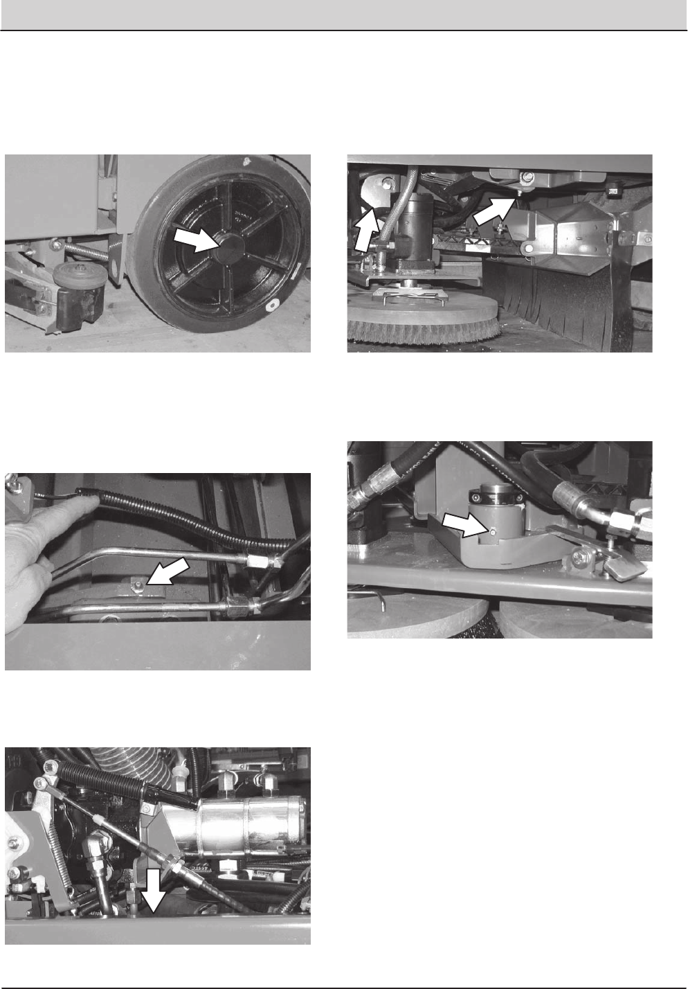
FRONT WHEEL SUPPORT BEARING
Lubricate the front wheel support bearings after
every 200 hours of operation. Both front wheel
support grease fittings are located underneath the
frame support plate.
STEERING CYLINDER BEARING
Lubricate the steering cylinder after every 200
hours of operation. The steering cylinder bearing
is located next to the front wheel support.
The engine oil capacity for diesel engines is 6L
(6.35 qt) with oil lter.
36 T20 Service Information (5-2017)
MAINTENANCE
MAINTENANCE
REAR WHEEL BEARINGS
Inspect the rear wheel bearings for seal damage,
and repack and adjust every 400 hours of
operation. Use Lubriplate EMB grease (Tennant
part number 01433ï1).
TORQUE TUBESïCYLINDRICAL BRUSHES
Lubricate the torque tubes after every 200 hours
of operation. The torque tube grease fittings on
the operator side of the machine are located
beneath the fuel tank.
On the other side of the machine the torque tube
grease fittings are located beneath the propel
pump.
TORQUE TUBESïDISK BRUSHES
Lubricate the three torque tube fittings after every
200 hours of operation. The first two fittings are
located on each side of the machine and the third
is located above the center brush.
PIVOT SHAFTïDISK BRUSHES
Lubricate the pivot shaft after every 200 hours of
operation.
T20 Service Information (5-2017) 37
MAINTENANCE
MAINTENANCE
HYDRAULICS
FOR SAFETY: Before leaving or servicing
machine, stop on level surface, set parking
brake, turn off machine, and remove key.
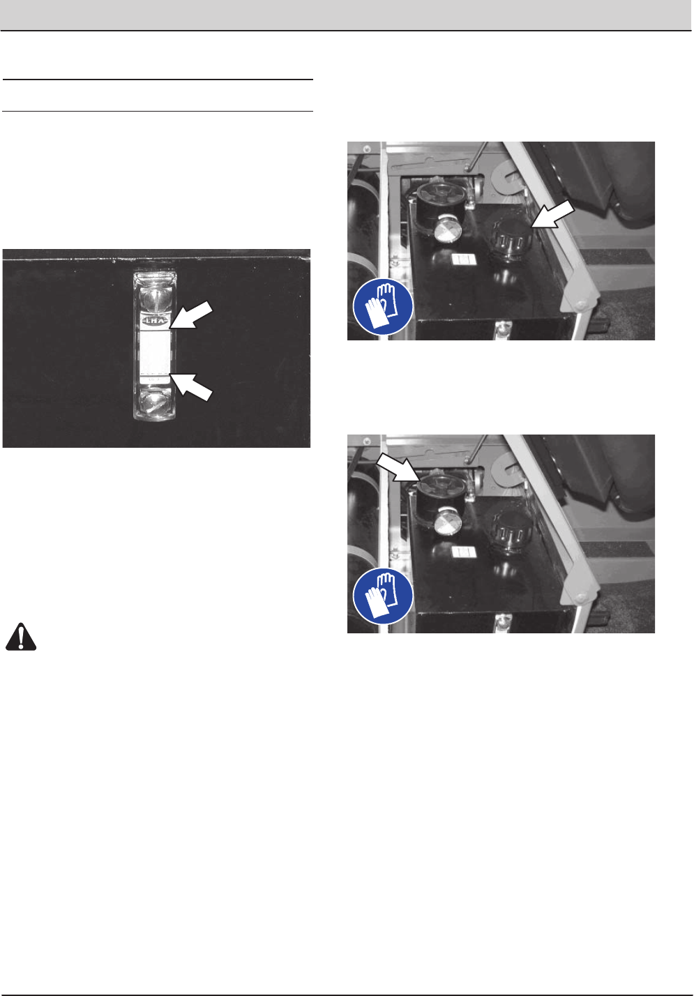
Check the hydraulic fluid level at operating
temperature daily. The hydraulic fluid level should
be between the two lines on the hydraulic gauge.
ATTENTION! Do not overfill the hydraulic fluid
reservoir or operate the machine with a low
level of hydraulic fluid in the reservoir.
Damage to the machine hydraulic system may
result.
Drain and refill the hydraulic fluid reservoir with
new TennantTrue premium hydraulic fluid after
every 2400 hours of operation.
WARNING: Burn hazard. Hot surface. Do
NOT touch.
Replace the filler cap after every 800 hours of
operation. Apply a light film of hydraulic fluid onto
the filler cap gasket before installing the cap onto
the reservoir.
Replace the hydraulic fluid filter after every 1200
hours of operation or if the hydraulic reservoir
gauge is in the yellow/red zone when the reservoir
hydraulic fluid is approximately 32C (90 F).
Replace the hydraulic strainer outlet after every
2400 hours of operation.
38 T20 Service Information (5-2017)
MAINTENANCE
MAINTENANCE
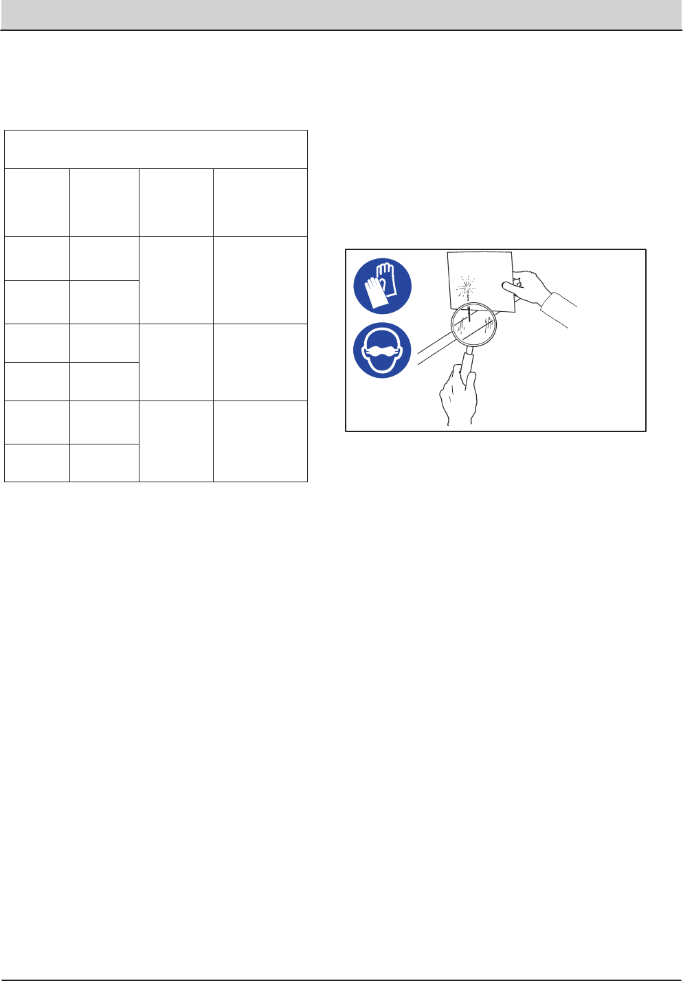
HYDRAULIC FLUID
There are three fluids available for different
ambient air temperature ranges:
TennantTrue premium
hydraulic fluid (Extended Life)
Part
Number
Capacity ISO
Grade
Viscosity
Index (VI)
Ambient Air
Temperature
Ranges
1057710 3.8 L
(1 gal)
ISO 100
VI 126 or
higher
19C
(65F) or
higher
1057711 19 L
(5 gal)
1069019 3.8 L
(1 gal)
ISO 68
VI 155 or
higher
7 to 43C
(45 to
110F)
1069020 19 L
(5 gal)
1057707 3.8 L
(1 gal)
ISO 32
VI 163 or
higher
16C
(60F) or
lower
1057708 19 L
(5 gal)
If using a locally-available hydraulic fluid, be sure
the specifications match Tennant hydraulic fluid
specifications. Substitute fluids can cause
premature failure of hydraulic components.
ATTENTION! Hydraulic components depend
on system hydraulic fluid for internal
lubrication. Malfunctions, accelerated wear,
and damage will result if dirt or other
contaminants enter the hydraulic system.
HYDRAULIC HOSES
Check the hydraulic hoses after every 800 hours
of operation for wear or damage.
FOR SAFETY: When servicing machine, use
cardboard to locate leaking hydraulic fluid
under pressure.
High pressure fluid escaping from a very small
hole can almost be invisible, and can cause
serious injuries.
00002
Consult a physician immediately if injury results
from escaping hydraulic fluid. Serious infection or
reaction can occur if proper medical treatment is
not given immediately.
Contact a mechanic or supervisor if a leak is
discovered.
T20 Service Information (5-2017) 39
MAINTENANCE
MAINTENANCE
ENGINE
FOR SAFETY: Before leaving or servicing
machine, stop on level surface, set parking
brake, turn off machine, and remove key.
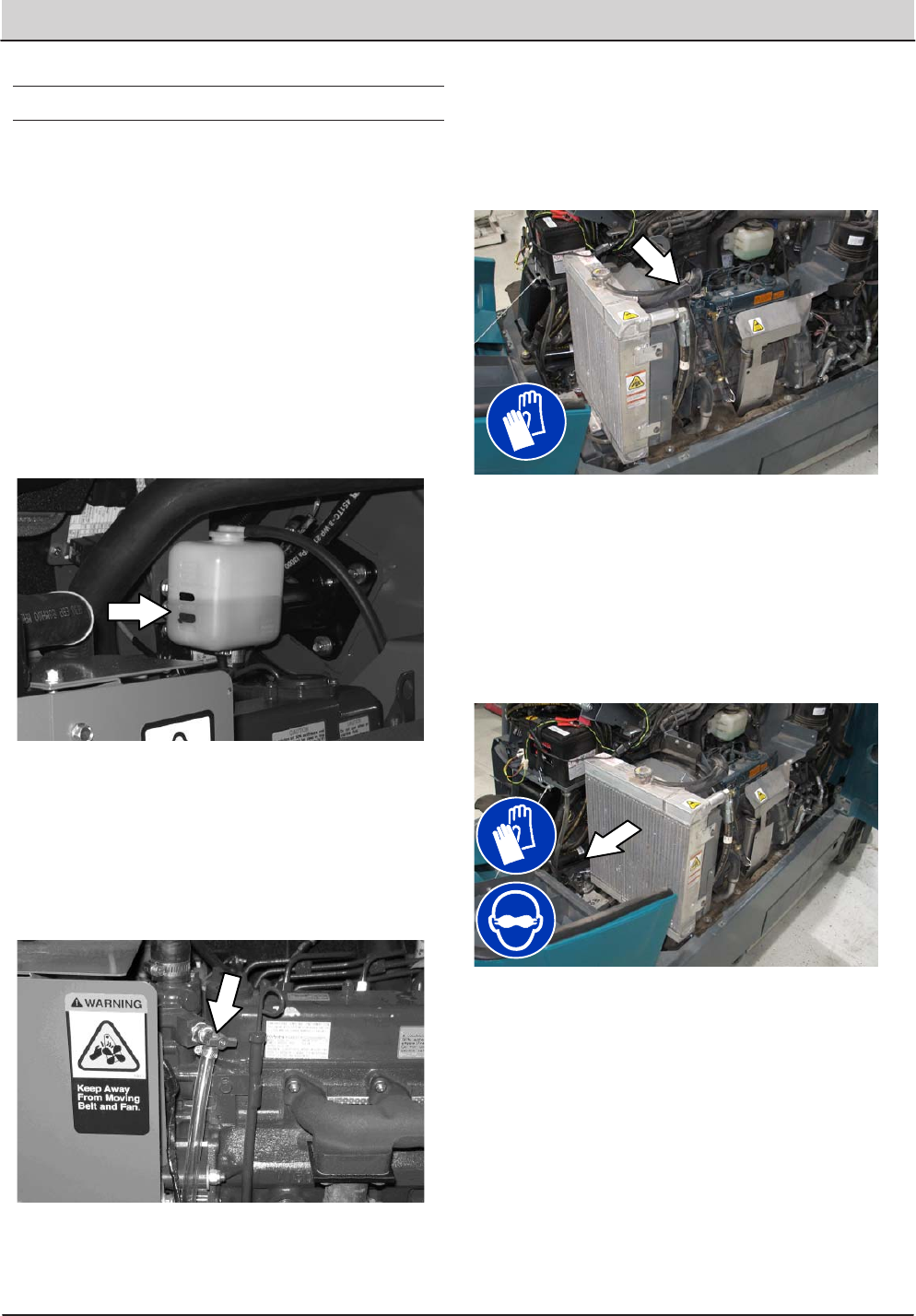
COOLING SYSTEM
FOR SAFETY: When servicing machine, avoid
contact with hot engine coolant. Do not
remove cap from radiator when engine is hot.
Allow engine to cool.
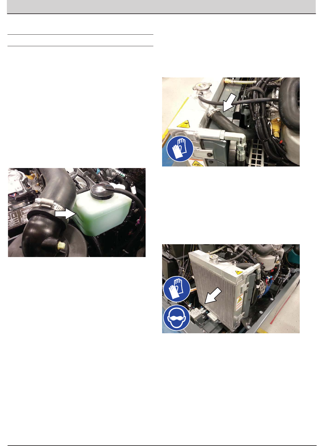
Check the coolant level in the reservoir daily. The
coolant level must be between the indicator marks
when the engine is cold. Refer to the coolant
manufacture for water/coolant mixing instructions.
Flush the radiator and the cooling system after
every 800 hours of operation.
The cooling system must be completely filled with
coolant to keep the engine from overheating.
Check the radiator hoses and clamps after every
200 hours of operation. Tighten loose clamps.
Replace damaged hoses and clamps.
Check the radiator hoses for cracks and
deteriation after every 1000 hours of operation.
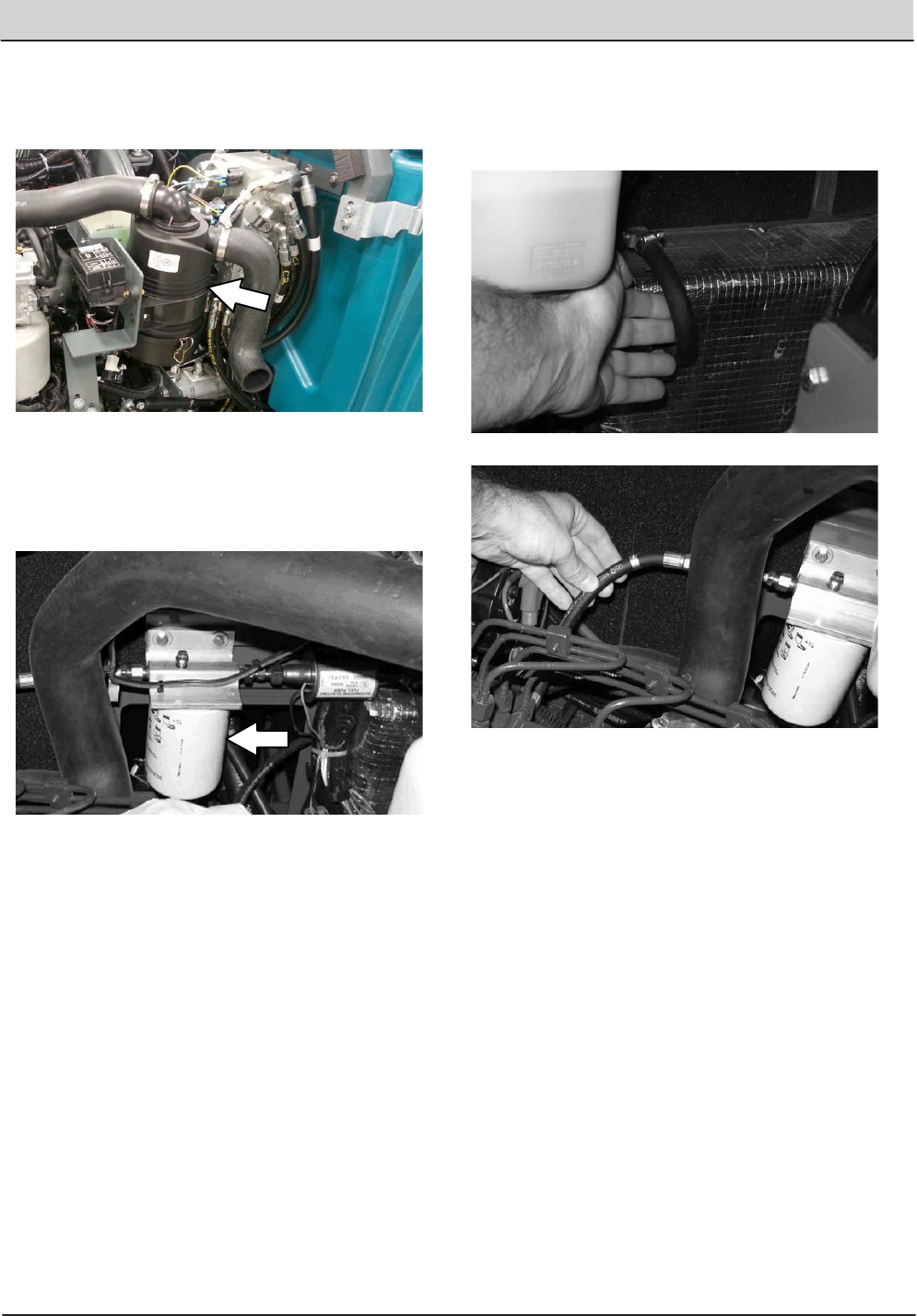
Check the radiator core exterior and hydraulic
cooler fins for debris after every 100 hours of
operation. Blow or rinse all dust through the grille
and radiator fins, in the opposite direction of
normal air flow. Be careful to not bend the cooling
fins when cleaning. Clean thoroughly to prevent
the fins from becoming encrusted with dust. To
avoid cracking the radiator, allow the radiator and
cooler fins to cool before cleaning.
ENGINE - GAS/LPG
40 T20 Service Information (5-2017)
MAINTENANCE
MAINTENANCE
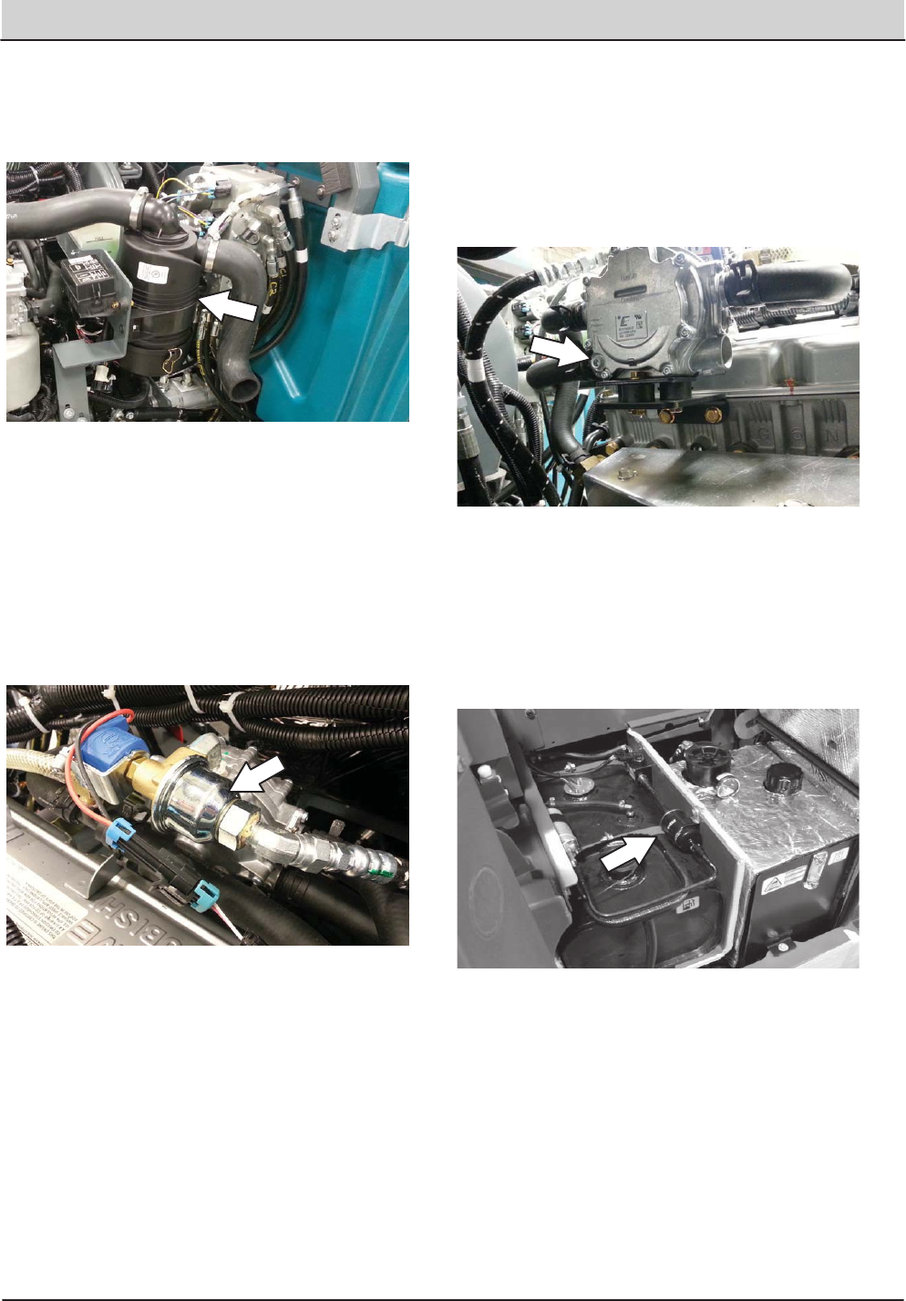
AIR FILTER
Replace the air filter after every 400 hours of
operation.
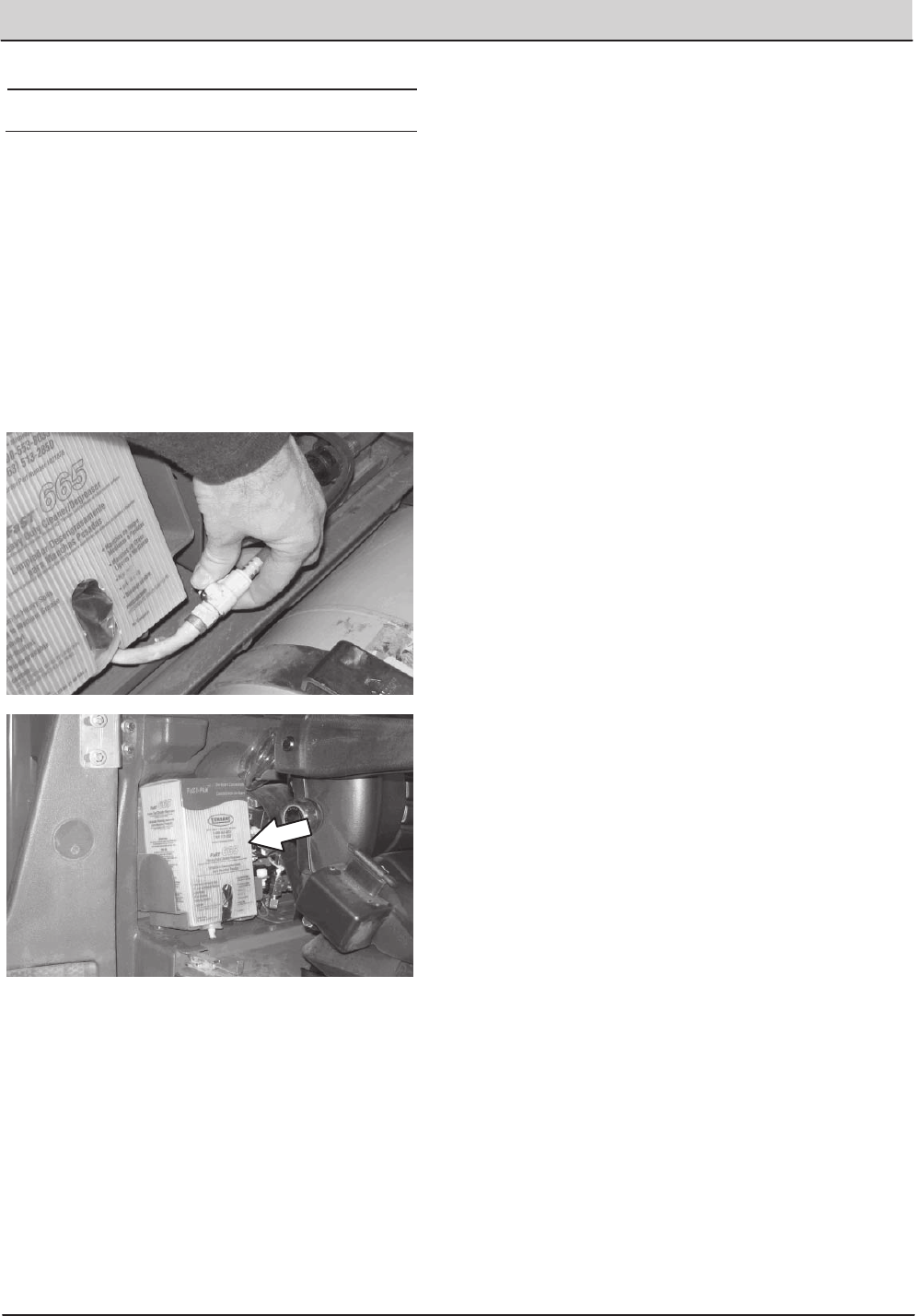
FUEL FILTER (LPG)
Replace the LPG fuel filter after every 400 hours
of operation.
Disassemble the fuel lock off valve to access the
LPG fuel filter.
FOR SAFETY: When servicing machine, keep
flames and sparks away from fuel system
service area. Keep area well ventilated.
LPG VAPORIZER
Drain oil buildup in the LPG vaporizer after every
100 hours of operation.
FOR SAFETY: When servicing machine, keep
flames and sparks away from fuel system
service area. Keep area well ventilated.
FUEL FILTER (Gasoline)
Replace the gasoline fuel filter after every 400
hours of operation.
FOR SAFETY: When servicing machine, keep
flames and sparks away from fuel system
service area. Keep area well ventilated.
T20 Service Information (5-2017) 41
MAINTENANCE
MAINTENANCE
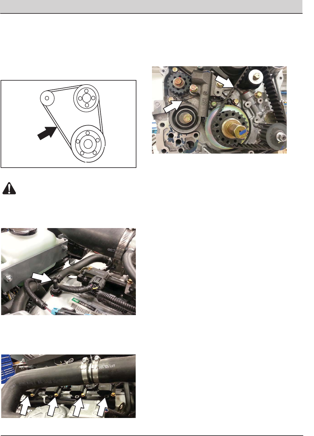
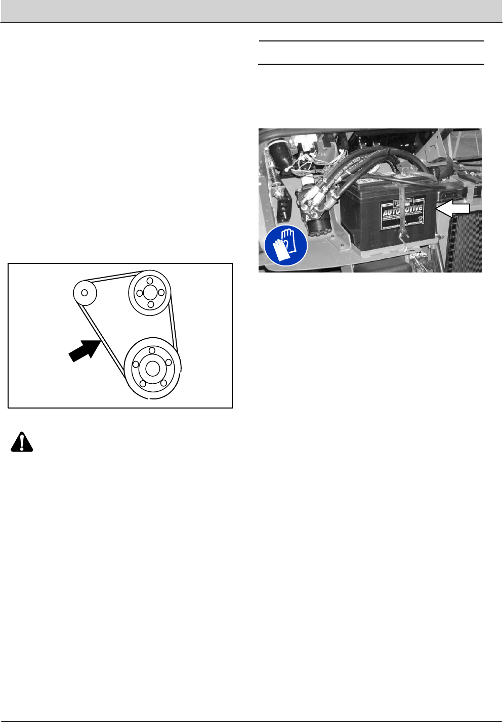
ENGINE BELT
Check the belt tension after every 50 hours of
operation. Adjust tension as necessary. Proper
belt tension is 13 mm (0.50 in) from a force of 4 to
5 kg (8 to 10 lb) applied at the mid-point of the
longest span.
WARNING: Moving belt and fan. Keep
away.
PCV SYSTEM
Inspect the PCV system after every 100 hours of
operation.
SPARK PLUGS ï MITSUBISHI ENGINES
Replace the spark plugs after every 1000 hours of
operation.
CAMSHAFT AND BALANCE SHAFT BELTS ï
MITSUBISHI ENGINES
Replace the camshaft and balance shaft belts
after every 5000 hours of operation.
BATTERY
Clean and tighten the battery connections after
the first 50 hours of operation and after every 800
hours after that. Do not remove the vent plugs
from the battery or add water to the battery.
FOR SAFETY: When servicing machine, avoid
contact with battery acid.
42 T20 Service Information (5-2017)
MAINTENANCE
MAINTENANCE
70 T20 Diesel 9016250 (08−2016)
ENGINE
FOR SAFETY: Before leaving or servicing
machine, stop on level surface, set parking
brake, turn off machine, and remove key.
COOLING SYSTEM
FOR SAFETY: When servicing machine, avoid
contact with hot engine coolant. Do not
remove cap from radiator when engine is hot.
Allow engine to cool.
Check the coolant level in the reservoir daily. The
coolant level must be between the indicator marks
when the engine is cold. Refer to the coolant
manufacture for water/coolant mixing instructions.
Flush the radiator and the cooling system after
every 800 hours of operation.
The cooling system must be completely filled with
coolant to keep the engine from overheating.
When filling the cooling system, open the drain
cock to bleed the air from the system.
Check the radiator hoses and clamps after every
200 hours of operation. Tighten loose clamps.
Replace damaged hoses and clamps.
Check the radiator hoses for cracks and
deterioration after every 1000 hours of operation.
Check the radiator core exterior and hydraulic
cooler fins for debris after every 100 hours of
operation. Blow or rinse all dust through the grille
and radiator fins, in the opposite direction of
normal air flow. Be careful to not bend the cooling
fins when cleaning. Clean thoroughly to prevent
the fins from becoming encrusted with dust. To
avoid cracking the radiator, allow the radiator and
cooler fins to cool before cleaning.
Home
Find...
Go To..
Home
Find...
Go To..
ENGINE - DIESEL
T20 Service Information (5-2017) 43
MAINTENANCE
MAINTENANCE
71
T20 Diesel 9016250 (08−2016)
AIR FILTER
Replace the air filter after every 400 hours of
operation.
FUEL FILTER
The fuel filter removes impurities from the fuel.
Replace the fuel filter after every 400 hours of
operation.
FOR SAFETY: When servicing machine, keep
flames and sparks away from fuel system
service area. Keep area well ventilated.
FUEL LINES
Check the fuel lines every 50 hours of operation.
If the clamp band is loose, apply oil to the screw
of the band and securely tighten the band.
The rubber fuel lines can become worn−out
whether the engine has been used much or not.
Replace the fuel lines and clamp bands every two
years.
FOR SAFETY: When servicing machine, keep
flames and sparks away from fuel system
service area. Keep area well ventilated.
If the fuel lines and clamp bands are found worn
or damaged before two years’ time; replace or
repair them at once. Bleed the fuel system after
replacement of any fuel lines, see PRIMING THE
FUEL SYSTEM. When the fuel lines are not
installed, plug both ends with clean cloth or paper
to prevent dirt from entering the lines. Dirt in the
lines can cause fuel injection pump malfunction.
Home
Find...
Go To..
Home
Find...
Go To..
44 T20 Service Information (5-2017)
MAINTENANCE
MAINTENANCE
72 T20 Diesel 9016250 (08−2016)
PRIMING THE FUEL SYSTEM
Typical diesel fuel systems require priming to
remove pockets of air from the fuel lines and fuel
components. This is usually required after running
out of fuel, changing fuel filter elements or
repairing a fuel system component. Air in the fuel
prevents smooth engine operation.
This fuel system however is self-priming. The
return line comes from the top of the injector that
allows the air to escape through the return line.
ENGINE BELT
Check the belt tension after every 50 hours of
operation. Adjust tension as necessary. Proper
belt tension is 13 mm (0.50 in) from a force of 4 to
5 kg (8 to 10 lb) applied at the mid-point of the
longest span.
WARNING: Moving belt and fan. Keep
away.
BATTERY
Clean and tighten the battery connections after
the first 50 hours of operation and after every 800
hours after that. Do not remove the vent plugs
from the battery or add water to the battery.
FOR SAFETY: When servicing machine, avoid
contact with battery acid.
Home
Find...
Go To..
Home
Find...
Go To..
T20 Service Information (5-2017) 45
MAINTENANCE
MAINTENANCE
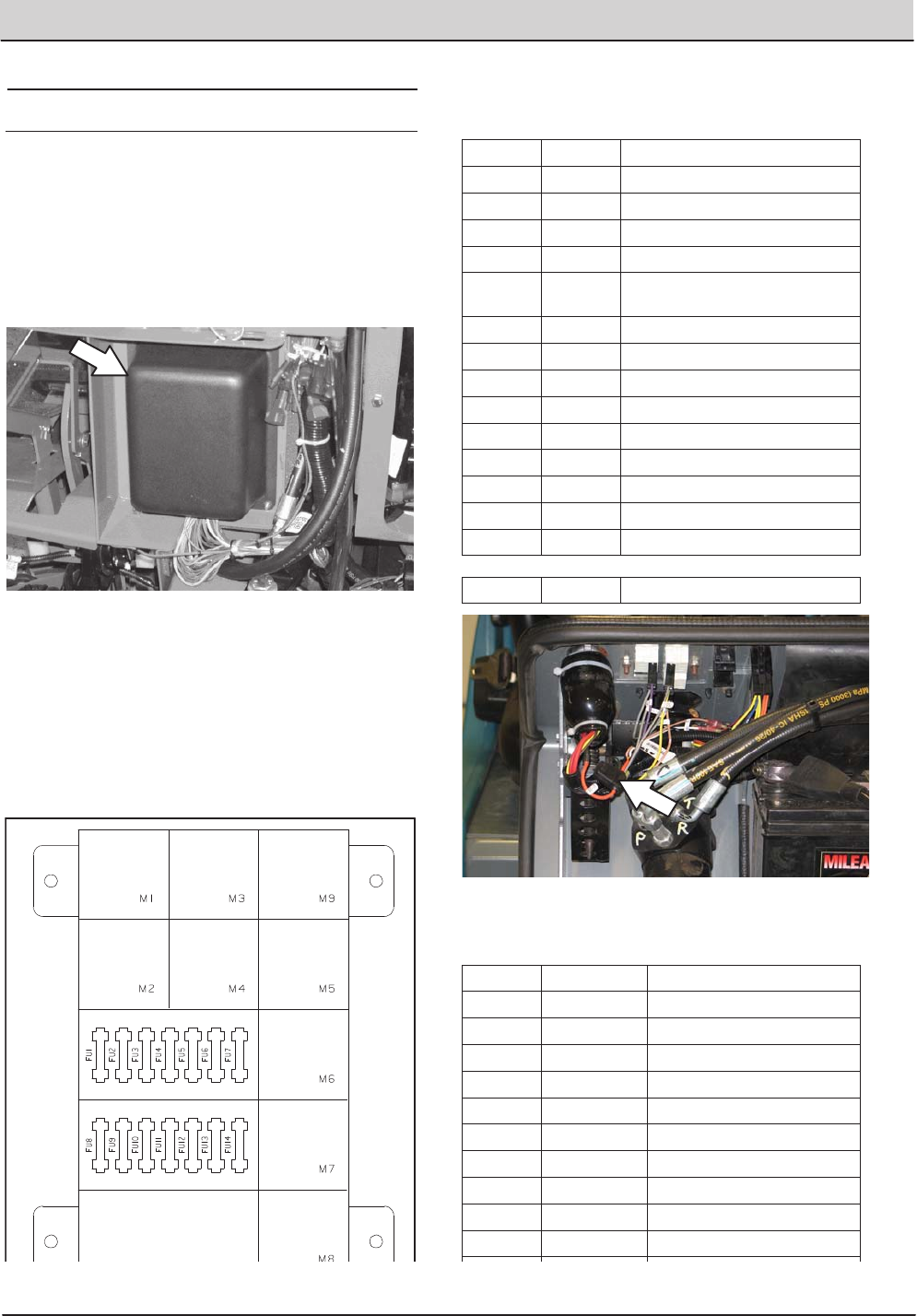
FUSES AND RELAYS
RELAY PANEL FUSES AND RELAYS
Fuses are one-time protection devices designed
to protect the wire harness by stopping the flow of
current in the event of a circuit overload. Relays
switch the electrical power going to the machine
electrical systems on/off. Remove the relay panel
cover to access fuses and relays.
NOTE: Always replace a fuse with a fuse of the
same amperage. Extra 15 Amp fuses are
provided inside the relay panel drawer on the
relay panel.
Refer to the diagram below for locations of the
fuses and relays on the relay panel. The M10
relay for the optional spray nozzle is located
behind the battery.
Refer to the table below for the fuses and circuits
protected.
Fuse Rating Circuit Protected
FU1 15 A Auxiliary Relays/Engine Controls
FU2 15 A Not Used
FU3 15 A Horn
FU4 15 A Not Used
FU5 15 A Scrub Vacuum/Main Brush/
Squeegee Down
FU6 15 A Enable/Side Brush
FU7 15 A Solution/Auto Fill/Reverse
FU8 15 A ES/FaST/Detergent/Spray Wand
FU9 15 A Lights
FU10 15 A Unswitched B+ for controller board
FU11 15 A Not Used: Options
FU12 15 A Spray Nozzle Pump
FU13 15 A Not Used
FU14 15 A Not Used
ï20 A ecïH2O (near ignition switch)
Refer to the table below for the relays and circuits
controlled.
Relay Rating Circuit Controlled
M1 12 VDC, 40 A Auxiliary 1
M2 12 VDC, 40 A Auxiliary 2
M3 12 VDC, 40 A Not Used
M4 12 VDC, 40 A Reverse
M5 12 VDC, 40 A Horn
M6 12 VDC, 40 A Shutdown
M7 12 VDC, 40 A Starter
M8 12 VDC, 40 A Not Used
M9 12 VDC, 40 A Not Used
M10 12 VDC. 40 A Not Used
M11 12 VDC. 40 A FaST Water Pump (located in
FaST harness)
M12 12 VDC. 40 A Spray Wand (located in Spray
wand harness)
46 T20 Service Information (5-2017)
MAINTENANCE
MAINTENANCE
ENGINE HARNESS FUSES AND RELAYS
The engine harness fuses and relays are located
in the fuse box inside the engine compartment.
Refer to the fuse box cover for locations of engine
harness fuses and relays.
NOTE: Always replace a fuse with a fuse of the
same amperage.
OPTIONAL RELAYS
The optional spray nozzle or pressure wand relay
is located behind the battery. The optional FaST
scrubbing system relay is located behind the seat.
Relay Rating Circuit Controlled
ï12 VDC. 40 A Spray Wand
ï12 VDC. 40 A Pressure Washer
ï12 VDC. 40 A FaST
CIRCUIT BREAKERS (ecïH2O)
Circuit breakers are resettable electrical circuit
protection devices that stop the flow of current in
the event of a circuit overload. Once a circuit
breaker is tripped, allow breaker to cool and then
press the reset button to manually reset the
breaker.
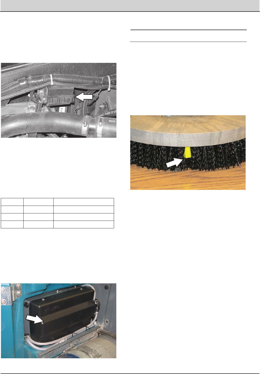
SCRUB BRUSHES AND PADS
The machine can be equipped with either disk or
cylindrical scrub brushes, or cleaning pads. Check
scrub brushes or pads daily for wire or string
tangled around the brush or brush drive hub. Also
check brushes or pads for damage and wear.
DISK BRUSHES
Replace the brush when it no longer cleans
effectively or when the bristles are worn down to
the yellow indicators.
Cleaning pads must be placed on pad drivers
before they are ready to use. The cleaning pad is
held in place the center disk.
Cleaning pads need to be cleaned immediately
after use with soap and water. Do not wash the
pads with a pressure washer. Hang pads, or lay
pads flat to dry.
NOTE: Always replace brushes and pads in sets.
Otherwise one brush or pad will be more
aggressive than the other.
T20 Service Information (5-2017) 47
MAINTENANCE
MAINTENANCE
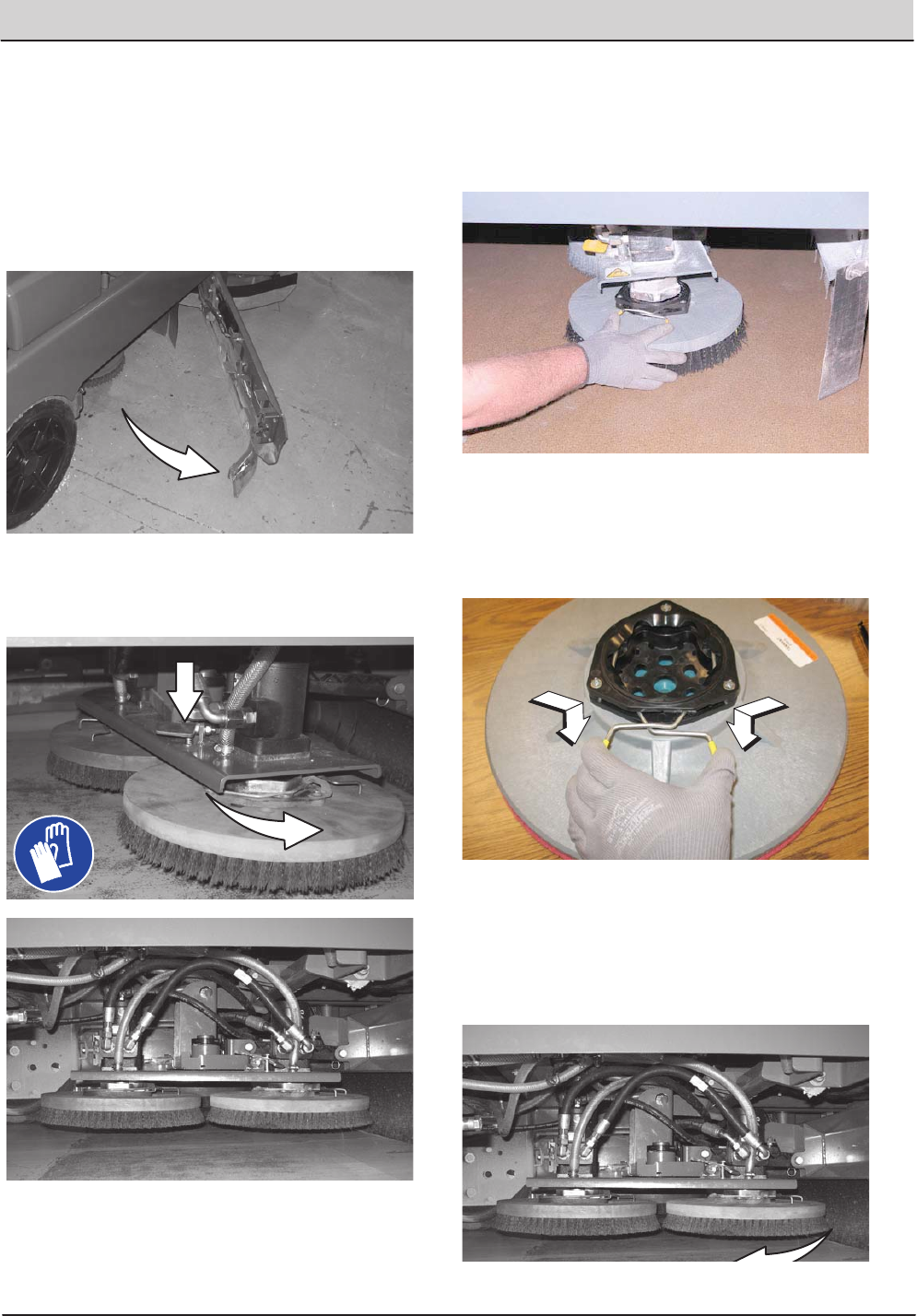
REPLACING DISK BRUSHES OR PAD DRIVER
1. Raise the scrub head.
FOR SAFETY: Before leaving or servicing
machine, stop on level surface, set parking
brake, turn off machine, and remove key.
2. Open the right outer brush door.
3. Hold down the release lever and rotate the
adjustable disk brush head until it is possible
to access the center brush.
4. Turn the brushes until the spring handles are
visible.
5. Squeeze the spring handles and let the
brushes drop to the floor.
6. Remove the brushes from underneath the
scrub head.
7. Set the brush spring open on the new brush
to make installation easier.
8. Place the new brushes underneath the scrub
head and lift each brush up onto the hub until
the brush locks onto the hub.
9. Rotate the disk brush head back to the scrub
position until the head locks into place.
48 T20 Service Information (5-2017)
MAINTENANCE
MAINTENANCE
10. Close the right outer brush door.
11. Open the left outer brush door and repeat the
procedure for the left brush.
NOTE: The center brush can only be accessed
from the right side of the machine.
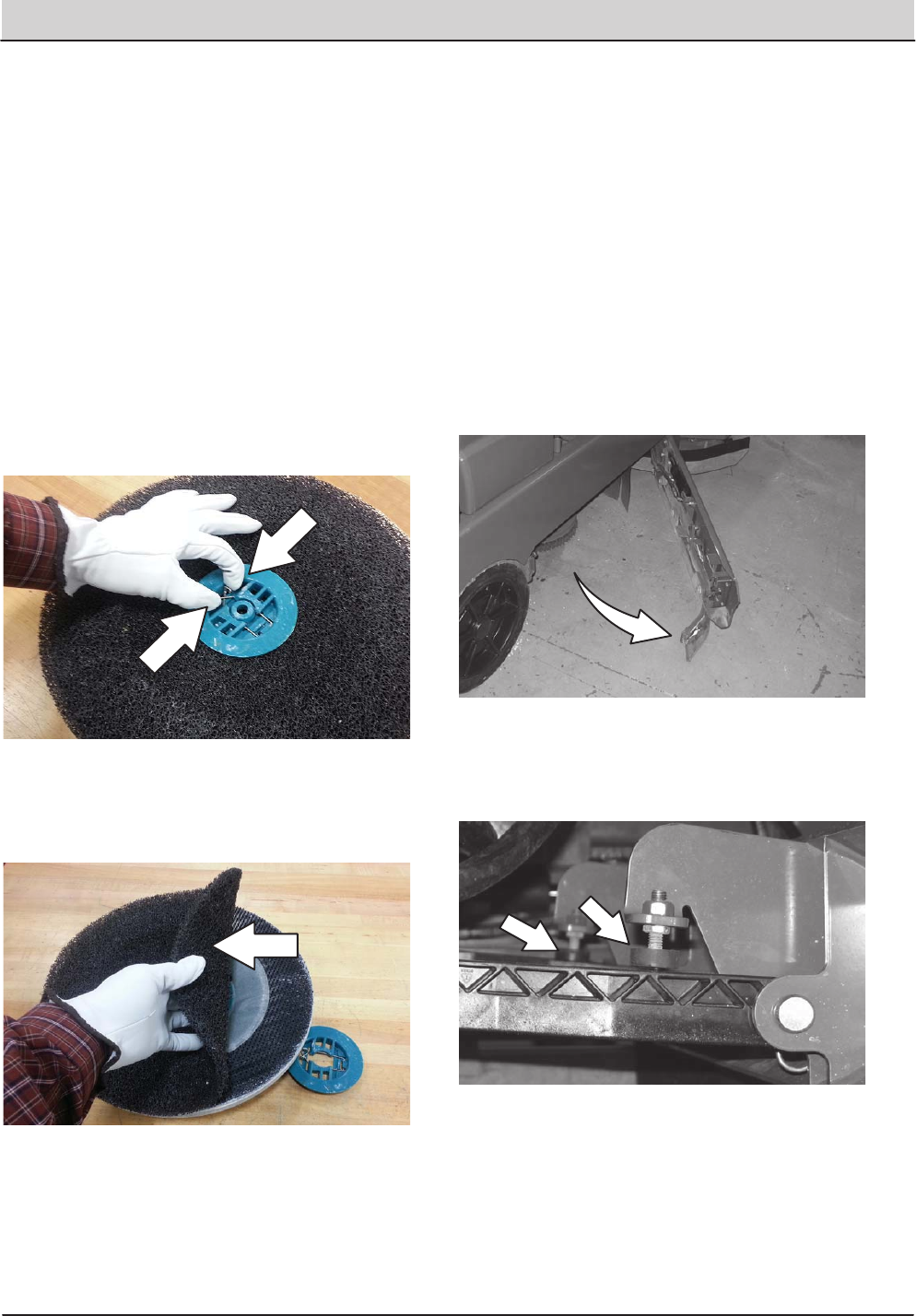
REPLACING DISK PADS
FOR SAFETY: Before leaving or servicing
machine, stop on level surface, set parking
brake, turn off machine, and remove key.
1. Remove the pad driver from the machine.
2. Squeeze the spring clip together to remove
the center disk.
3. Flip or replace the scrub pad, center the scrub
pad on the pad driver. Then reinstall the
center disk to secure the pad in place on the
pad driver.
4. Reinsert the pad driver into the machine.
CHECKING THE DISK SCRUB HEAD STOP
BUMPERS
The disk scrub head stop bumpers keep the scrub
head parallel with the floor when in the raised
position. This protects the brushes when
transporting. Check the lift stop bumpers after
every 100 hours of operation for wear or damage.
1. Raise the scrub head.
FOR SAFETY: Before leaving or servicing
machine, stop on level surface, set parking
brake, turn off machine, and remove key.
2. Open the right and left outer brush doors.
3. Inspect the scrub head stop bumpers. Adjust
the bumpers if the scrub head is not parallel
with the floor. Replace worn or damaged
bumpers.
T20 Service Information (5-2017) 49
MAINTENANCE
MAINTENANCE
CYLINDRICAL BRUSHES
FOR SAFETY: Before leaving or servicing
machine, stop on level surface, set parking
brake, turn off machine, and remove key.
Check the main brushes daily for tangled wire or
string, wear, and damage.
Replace the brushes when they no longer clean
effectively.
Rotate the brushes from front to rear after every
50 hours of machine operation for maximum
brush life and best scrubbing performance.
NOTE: Replace brushes in sets of two. Otherwise
one scrub brush may scrub more aggressively
than the other.
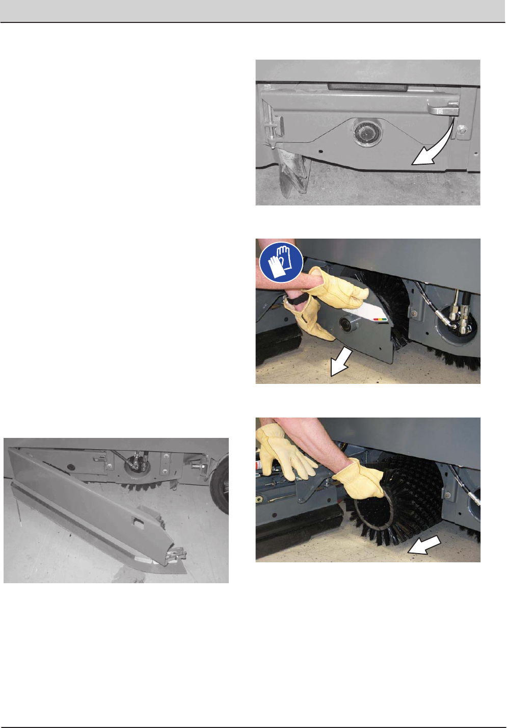
REPLACING OR ROTATING CYLINDRICAL
BRUSHES
The front brush can be accessed on the left side
of the machine and rear brush can be accessed
on the right side of the machine.
1. Raise the scrub head.
FOR SAFETY: Before leaving or servicing
machine, stop on level surface, set parking
brake, turn off machine, and remove key.
2. Open the outer brush doors.
3. Open the inner brush doors.
4. Remove the brush idler plates.
5. Pull the brushes out from the scrub head.
50 T20 Service Information (5-2017)
MAINTENANCE
MAINTENANCE
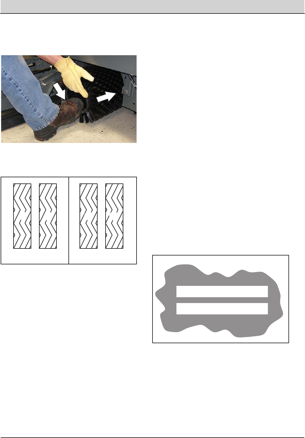
6. Install the new or rotated brushes by pushing
down on the ends while sliding them onto the
drive motor hubs.
7. If rotating the brushes, always rotate the front
with the back so that they wear evenly. They
may be rotated endïforïend as well.
Before After
A B B A
8. Reinstall the brush idler plates.
9. Close the inner and outer brush doors.
10. Check the brush pattern and adjust if needed
after rotating them. Refer to CHECKING AND
ADJUSTING THE MAIN BRUSH PATTERN.
11. Check the brush pattern and adjust if needed
after rotating them. Refer to CHECKING
CYLINDRICAL BRUSH PATTERN.
CHECKING CYLINDRICAL BRUSH PATTERN
1. Apply chalk, or a similar marking material, to
a smooth and level section of the floor.
NOTE: If chalk or other material is not available,
allow the brush to spin on the floor for two
minutes. A polish mark will remain on the floor.
2. Raise the scrub head, then position the
brushes over the chalked area.
3. Set the parking brake.
4. Press the 1ïSTEP Scrub button to lower the
scrub head. Set the brush pressure to the
lowest setting and allow the brushes to
operate for 15 to 20 seconds. Keep the scrub
head in one spot in the chalked area.
5. Raise the scrub head, release the parking
brake, and drive the machine away from the
chalked area.
FOR SAFETY: Before leaving or servicing
machine, stop on level surface, set parking
brake, turn off machine, and remove key.
6. Observe the brush patterns. If the brush
pattern is the same width across the entire
length of each brush and both brushes are the
same width, no adjustment is necessary.
T20 Service Information (5-2017) 51
MAINTENANCE
MAINTENANCE
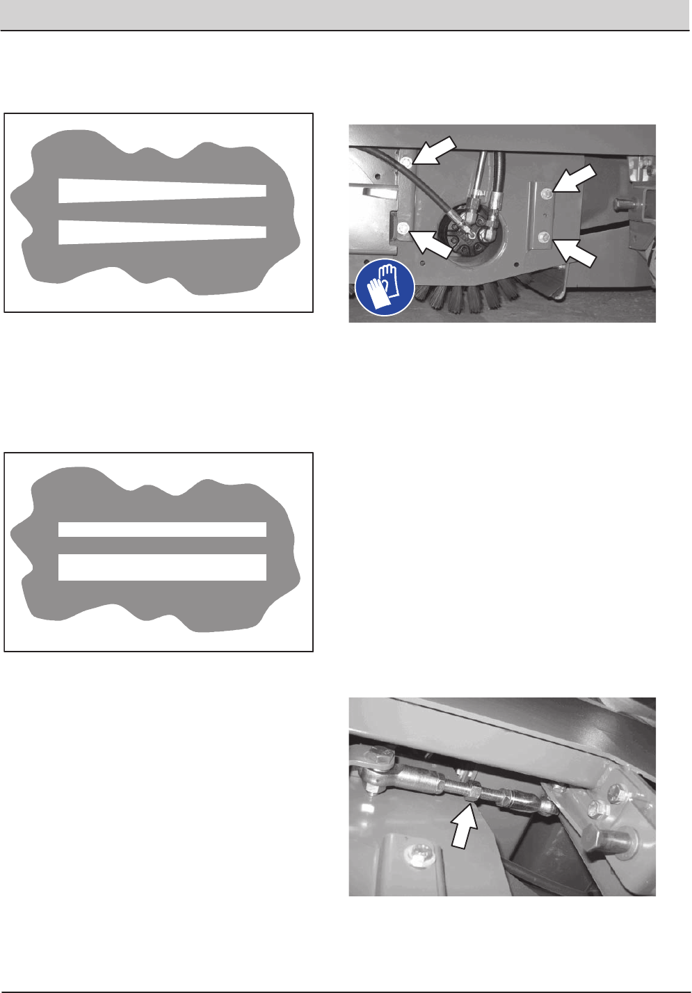
7. If the brush patterns are tapered, see
ADJUSTING THE CYLINDRICAL BRUSH
TAPER section of this manual.
8. The brush patterns should be 50 to 75 mm
(2 to 3 in) wide with the brushes in the
lowered position and both patterns should be
the same width. If the width of the brushes is
not the same, see ADJUSTING THE
CYLINDRICAL BRUSH WIDTH section of this
manual.
ADJUSTING THE CYLINDRICAL BRUSH TAPER
1. Loosen the four mounting bolts on the brush
drive housing.
2. Move the brush drive housing up to decrease
the pattern width on that side of the scrub
head or down to increase the pattern width on
that side of the scrub head.
3. Tighten the mounting bolts.
4. Recheck the pattern. Readjust if necessary.
ADJUSTING THE CYLINDRICAL BRUSH
WIDTH
1. Adjust the length of the drag links on both
sides of the scrub head. Lengthen the drag
links to increase the rear brush pattern width.
Shorten the drag links to increase the front
brush pattern. Always adjust the nut on each
drag link an equal number of turns.
NOTE: Two full turns of the drag link adjustment
bolt will change the brush pattern approximately
25 mm (1 in).
2. Recheck the pattern. Readjust if necessary.
52 T20 Service Information (5-2017)
MAINTENANCE
MAINTENANCE
SIDE BRUSH (OPTION)
FOR SAFETY: Before leaving or servicing
machine, stop on level surface, set parking
brake, turn off machine, and remove key.
Check the side brush daily for wear or damage.
Remove any tangled string or wire from the side
brush or side brush drive hub.
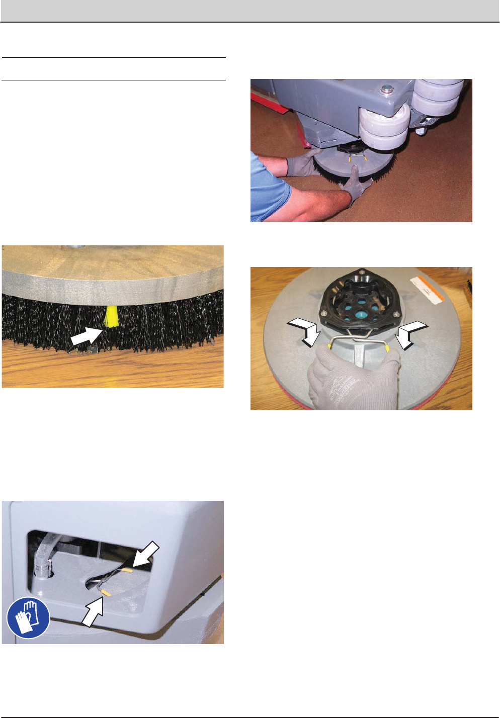
REPLACING THE SIDE BRUSH
Replace the brush when it no longer cleans
effectively or when the bristles are worn down to
the yellow indicators.
1. If necessary, raise the side brush.
2. Turn the brush until the spring handles are
visible through the access hole in the side
brush assembly.
3. Squeeze the spring handles and let the side
brush drop to the floor.
4. Remove the side brush from underneath the
side brush assembly.
5. Set the brush spring open on the new brush
to make installation easier.
6. Place the new side brush underneath the side
brush assembly and lift the side brush up onto
the side brush hub until the brush locks onto
the hub.
T20 Service Information (5-2017) 53
MAINTENANCE
MAINTENANCE
FaST SYSTEM
REPLACING THE FaSTïPAK CARTON
FOR SAFETY: Before leaving or servicing
machine, stop on level surface, set parking
brake, turn off machine, and remove key.
1. Open the side access door.
2. Slide the seat completely forward.
3. Squeeze the button on the FaST supply hose
connector, then pull the empty FaSTïPAK
carton out from the compartment and discard.
4. Remove the perforated knock outs from the
new FaSTïPAK carton. Do Not remove the
bag from the carton. Pull out the hose
connector located on the bottom of the bag
and remove the hose cap from the connector.
NOTE: The FaSTïPAK Floor Cleaning
Concentrate is specially designed for use with the
FaST system scrubbing application. NEVER use
a substitute. Other cleaning solutions may cause
FaST system failure.
5. Slide the FaSTïPAK carton into the
FaSTïPAK bracket.
6. Connect the FaST supply hose to the
FaSTïPAK hose connector.
7. Scrub with the FaST system for a few
minutes to allow the detergent to reach
maximum foaming.
54 T20 Service Information (5-2017)
MAINTENANCE
MAINTENANCE
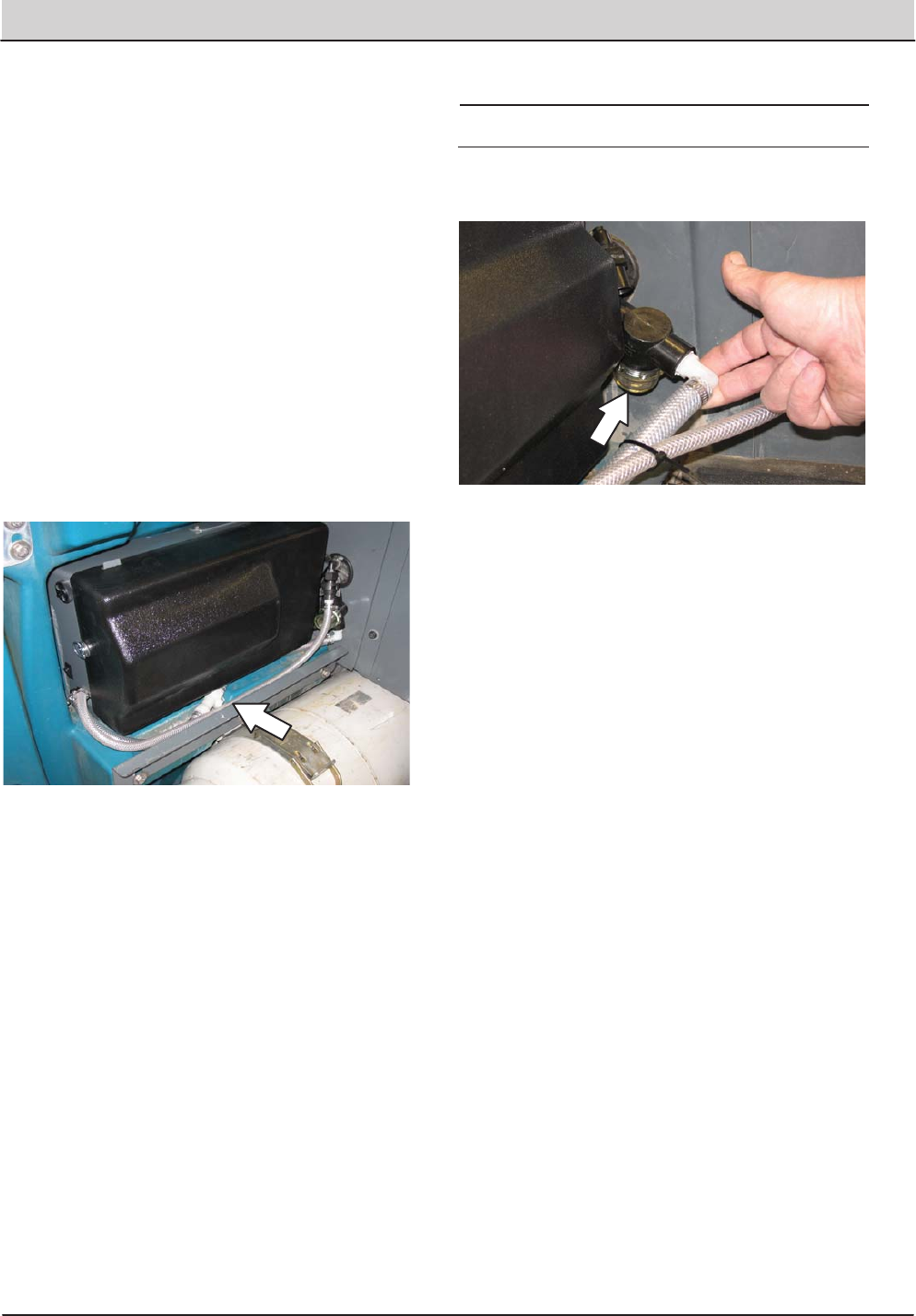
CLEANING THE FaST SUPPLY HOSE
CONNECTOR
Soak the connector in warm water if detergent
buildup is visible. When a FaSTïPAK carton is not
installed, store the supply hose connector on the
storing plug to prevent the hose from clogging.
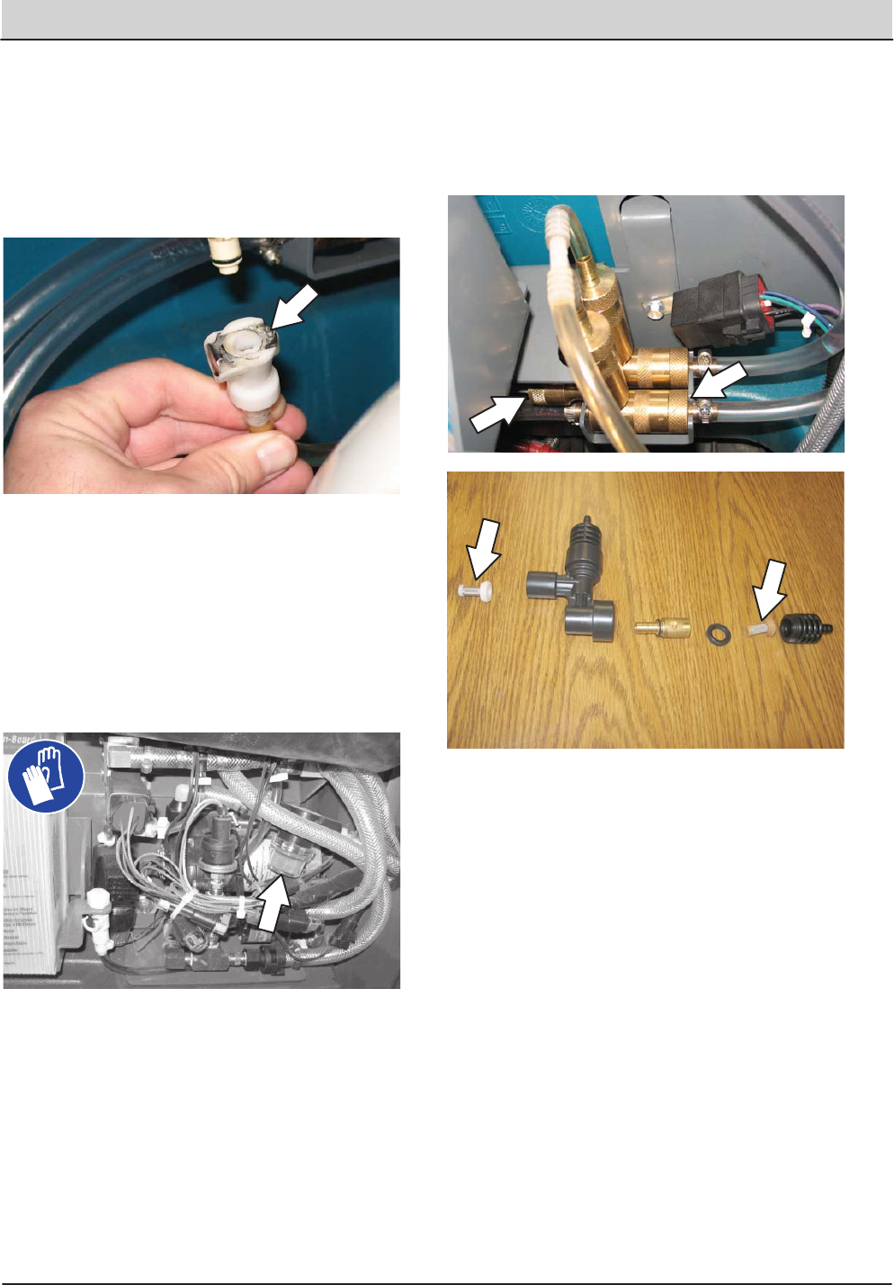
CLEANING THE FaST SYSTEM FILTER
SCREEN
The FaST system filter screen filters water from
the solution tank as the water flows into the FaST
system.
Remove the filter screen bowl and clean the filter
screen after every 50 hours of operation. Empty
the solution tank before removing the filter.
REPLACING THE FaST SYSTEM FILTERS
Replace the FaST system filters after every 1000
hours of operation. Empty the solution tank before
replacing the filters.
T20 Service Information (5-2017) 55
MAINTENANCE
MAINTENANCE
ecïH2O MODULE FLUSH PROCEDURE
This procedure is only required when an alarm
sounds and the ecïH2O system indicator light
begins to blink red.
FOR SAFETY: Before leaving or servicing
machine, stop on level surface, set parking
brake, turn off machine.
1. Remove both flush hoses from the storage
bag located behind the operator seat.
2. Lock the operator seat cover open.
3. Disconnect the ecïH2O system intake hose
from the solution supply hose and connect the
intake flush hose (gray connector) to the
ecïH2O system intake hose.
4. Disconnect the ecïH2O system outlet hose
from the hose to the scrub head and connect
the outlet flush hose (black connector) to the
ecïH2O system outlet hose.
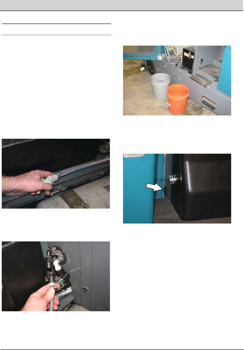
5. Place the ecïH2O system intake hose into a
container containing 5 gallons (19 liters) of
white or rice vinegar. Place the outlet hose
into an empty bucket.
6. Turn the key to the on position without starting
the engine.
7. Press and release the ecïH2O module flush
switch to start the flush cycle.
NOTE: The module will automatically shut off
when the flush cycle is complete (approx. 7
minutes). The module must run the full 7 minute
cycle in order to reset the system indicator light
and alarm.
56 T20 Service Information (5-2017)
MAINTENANCE
MAINTENANCE
8. After the 7 minute flush cycle, remove the
siphon hose from the container of vinegar and
place the siphon hose into a container of cool
clean water. Press the flush switch again to
rinse out any remaining vinegar from the
module. After 1ï2 minutes, press the flush
switch to turn off the module.
9. Disconnect the flush hoses from the ecïH2O
system intake hose and outlet hose and
return the flush hoses to the storage bag.
10. Reconnect ecïH2O intake and outlet hoses. If
the ecïH2O system indicator light continues
to flash, repeat the flush procedure. If the
problem persists, contact an Authorized
Service Center.
11. Insert the outlet and intake hoses between the
ecïH2O assembly and the bracket.
NOTE: The outlet and intake hoses must be down
between the ecïH2O assembly and the bracket so
they are not pinched or damaged when the operator
seat cover is closed.
12. Close the operator seat cover.
CLEANING THE ecïH2O FILTER SCREEN
Remove and clean the ecïH2O filter screen after
every 50 hours of operation.
T20 Service Information (5-2017) 57
MAINTENANCE
MAINTENANCE
SQUEEGEE BLADES
Check the squeegee blades for damage and wear
daily. When the blades become worn, rotate the
blades endïforïend or topïtoïbottom to a new
wiping edge. Replace blades when all edges are
worn.
Check the deflection of the squeegee blades daily
or when scrubbing a different type of surface.
Check the leveling of the rear squeegee every
100 hours of operation.
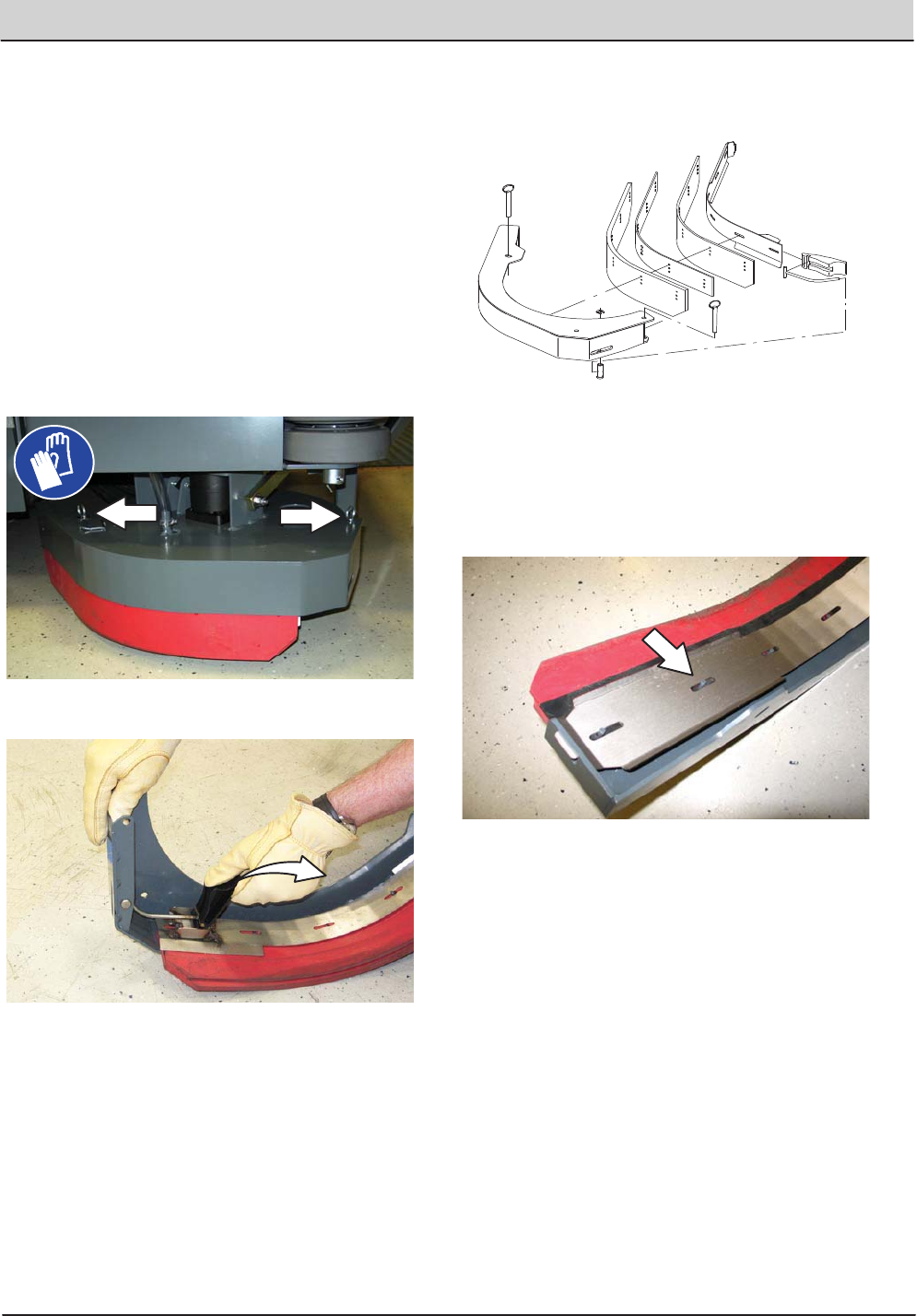
REPLACING (OR ROTATING) THE REAR
SQUEEGEE BLADES
1. Lower the scrub head.
FOR SAFETY: Before leaving or servicing
machine, stop on level surface, set parking
brake, and turn off machine.
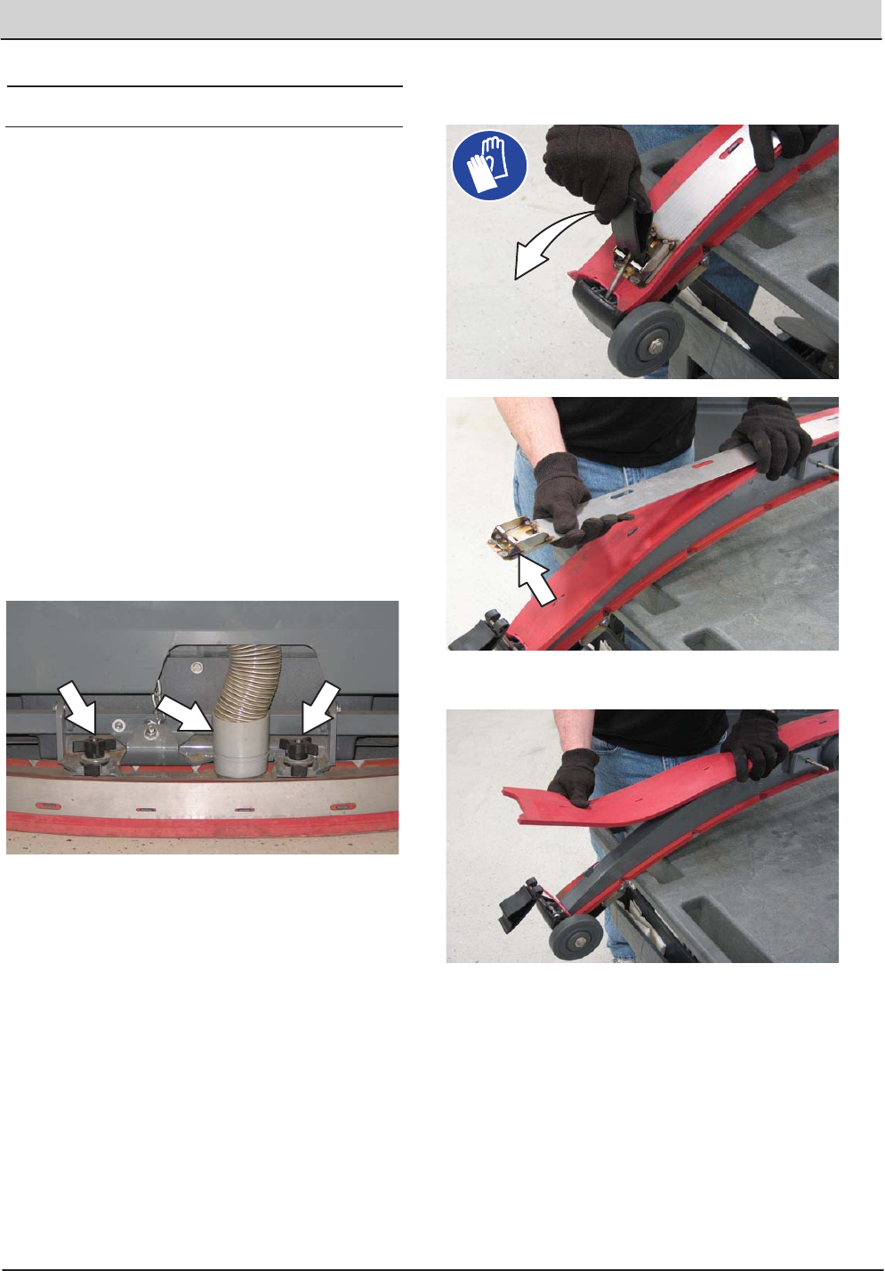
2. Disconnect the vacuum hose from the rear
squeegee assembly.
3. Remove both mounting knobs from the rear
squeegee assembly.
4. Turn on the machine, raise the scrub head,
and turn off the machine.
5. Remove the rear squeegee assembly from
the machine.
6. Loosen the rear retaining band tension latch
and open the retaining band.
7. Remove the rear squeegee.
58 T20 Service Information (5-2017)
MAINTENANCE
MAINTENANCE
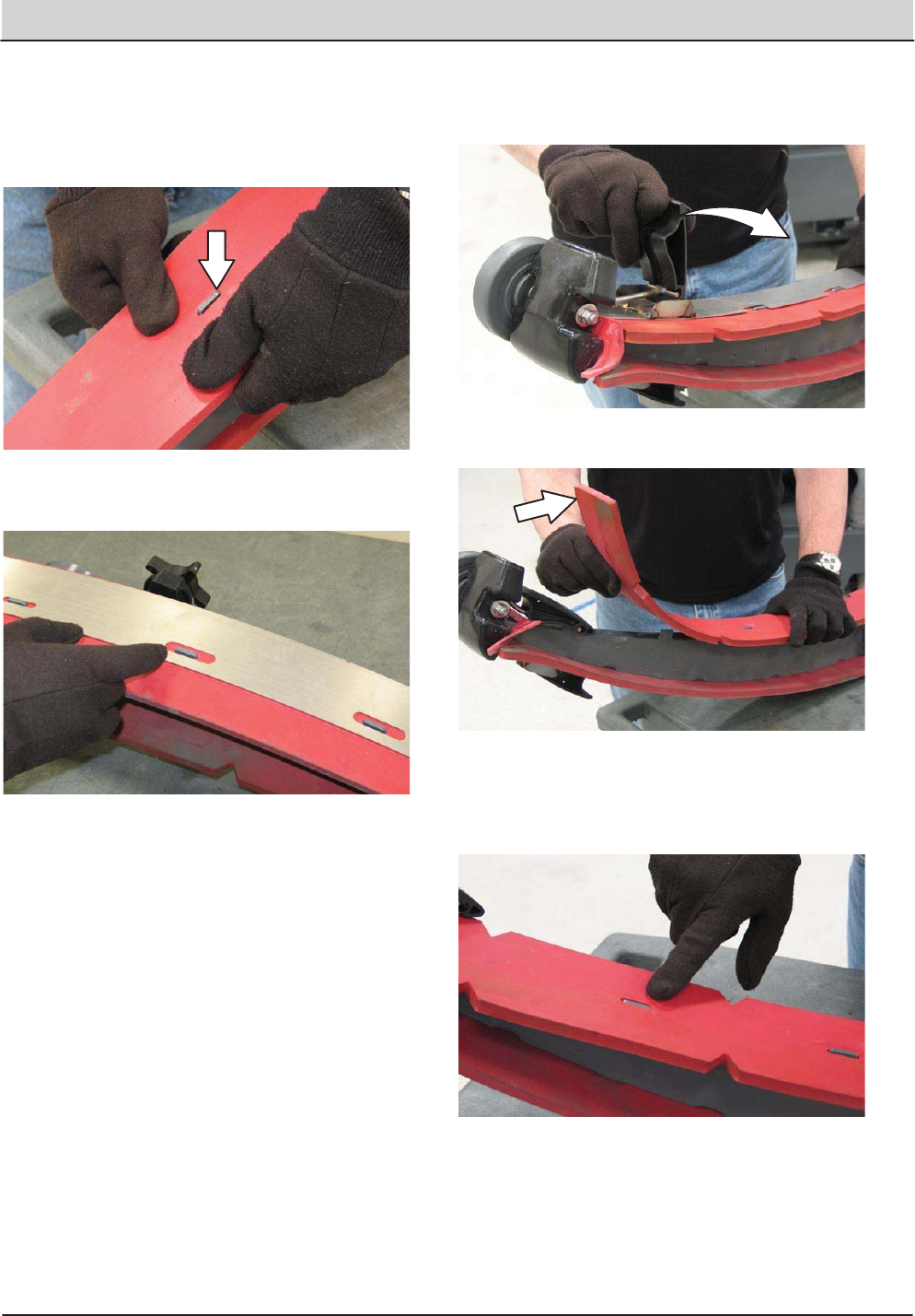
8. Install the new rear squeegee blade or rotate
the existing blade to the new edge. Be sure all
the holes in the squeegee blade are hooked
onto the tabs.
9. Reinstall the rear retaining band aligning the
tabs with the holes.
10. Tighten the rear retaining band tension latch.
11. Loosen the front retaining band tension latch
and open the retaining band.
12. Remove the front squeegee.
13. Install the new front squeegee blade or rotate
the existing blade to the new edge. Be sure
the holes in the squeegee blade are hooked
onto the tabs.
T20 Service Information (5-2017) 59
MAINTENANCE
MAINTENANCE
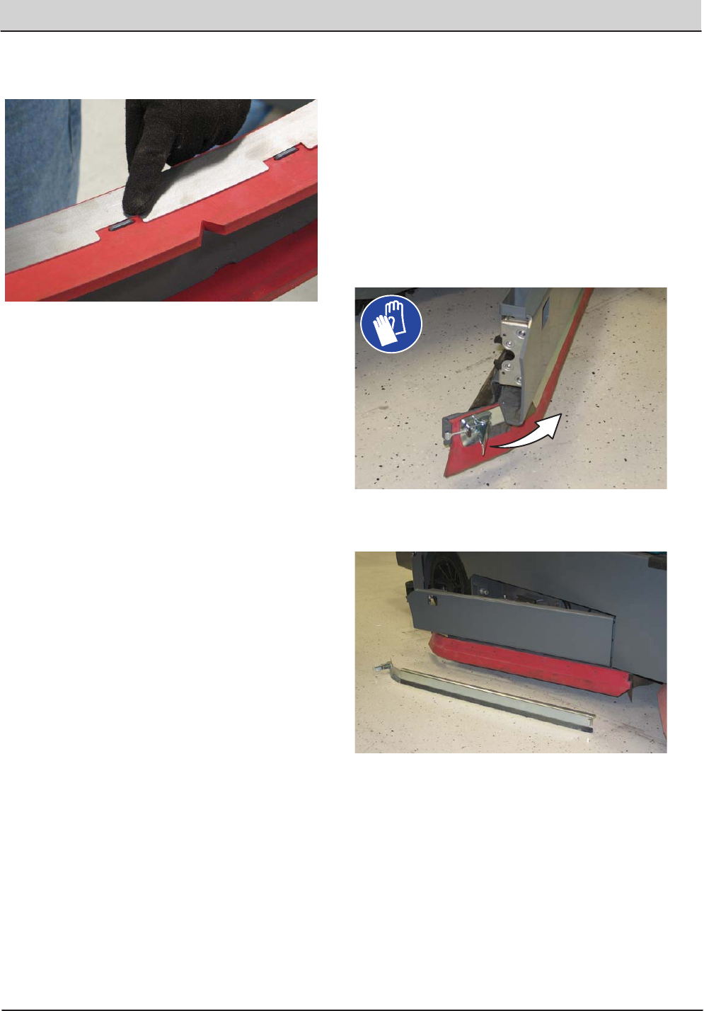
14. Reinstall the front retaining band aligning the
tabs with the notches.
15. Tighten the front retaining band tension latch.
16. Reinstall the rear squeegee assembly onto
the machine.
17. Check and adjust the rear squeegee if
necessary. Refer to ADJUSTING THE REAR
SQUEEGEE BLADE DEFLECTION and
LEVELING THE REAR SQUEEGEE sections
of this manual.
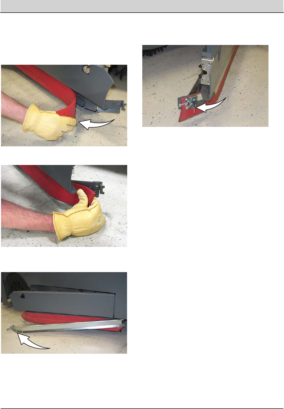
REPLACING OR ROTATING THE SIDE
SQUEEGEE BLADES
1. If necessary, raise the scrub head.
FOR SAFETY: Before leaving or servicing
machine, stop on level surface, set parking
brake, turn off machine, and remove key.
2. Open the outer brush doors.
3. Unhook the latch on the side squeegee
retaining band from the side squeegee
assembly.
4. Remove the retaining band from the side
squeegee assembly.
60 T20 Service Information (5-2017)
MAINTENANCE
MAINTENANCE
5. Remove the side squeegee blade. If the outer
edge of the squeegee blade is not worn,
rotate the squeegee blade with the blade from
the other side of the machine. Discard the
squeegee blade if both edges are worn.
6. Install the new or rotated squeegee blades.
7. Reattach the side squeegee retaining band to
the side squeegee assembly.
8. Hook the latch on the side squeegee retaining
band.
9. Close the outer brush door.
T20 Service Information (5-2017) 61
MAINTENANCE
MAINTENANCE
REPLACING OR ADJUSTING THE SIDE
BRUSH SQUEEGEE BLADE (OPTION)
FOR SAFETY: Before leaving or servicing
machine, stop on level surface, set parking
brake, turn off machine, and remove key.
Check the side brush squeegee blade for damage
and wear daily. Replace the blade if the leading
edge is torn or worn half-way through the
thickness of the blade.
1. Lower the scrub head.
2. Pull the pins and remove the squeegee
bumper.
3. Open the retaining band tension latch.
4. Remove the squeegees, spacer, and retainer
from the squeegee bumper.
NOTE: The side brush squeegee blades have
different holes for changing height adjustment.
5. Reinstall the squeegees, spacer, and retainer
to the squeegee bumper by aligning the
appropriate holes to the pins on the bumper.
6. Reinstall the retaining band tension latch.
7. Reinstall the squeegee bumper and reinsert
the pins.
62 T20 Service Information (5-2017)
MAINTENANCE
MAINTENANCE
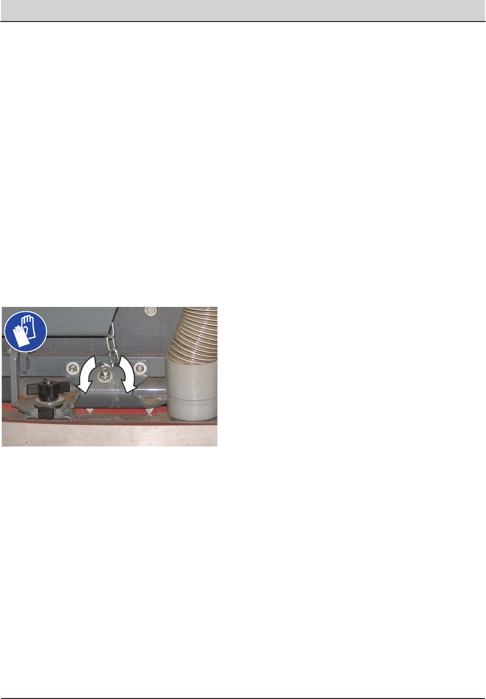
LEVELING THE REAR SQUEEGEE
Leveling the squeegee assures the entire length
of the squeegee blade is in even contact with the
surface being scrubbed. Perform this adjustment
on an even and level floor.
1. Lower the squeegee and drive the machine
forward a few meters (feet).
FOR SAFETY: Before leaving or servicing
machine, stop on level surface, set parking
brake, turn off machine, and remove key.
2. Look at the deflection of the squeegee over
the full length of the squeegee blade.
3. If the deflection is not the same over the full
length of the blade, turn the squeegee
levelling nut to make adjustments.
DO NOT disconnect the suction hose from
the squeegee frame when leveling squeegee.
4. Turn the squeegee leveling nut
counter-clockwise to decrease the deflection
at the ends of the squeegee blade.
Turn the squeegee leveling nut clockwise to
increase the deflection at the ends of the
squeegee blade.
5. Drive the machine forward with the squeegee
down to recheck the squeegee blade
deflection if adjustments were made.
6. Readjust the squeegee blade deflection if
necessary.
T20 Service Information (5-2017) 63
MAINTENANCE
MAINTENANCE
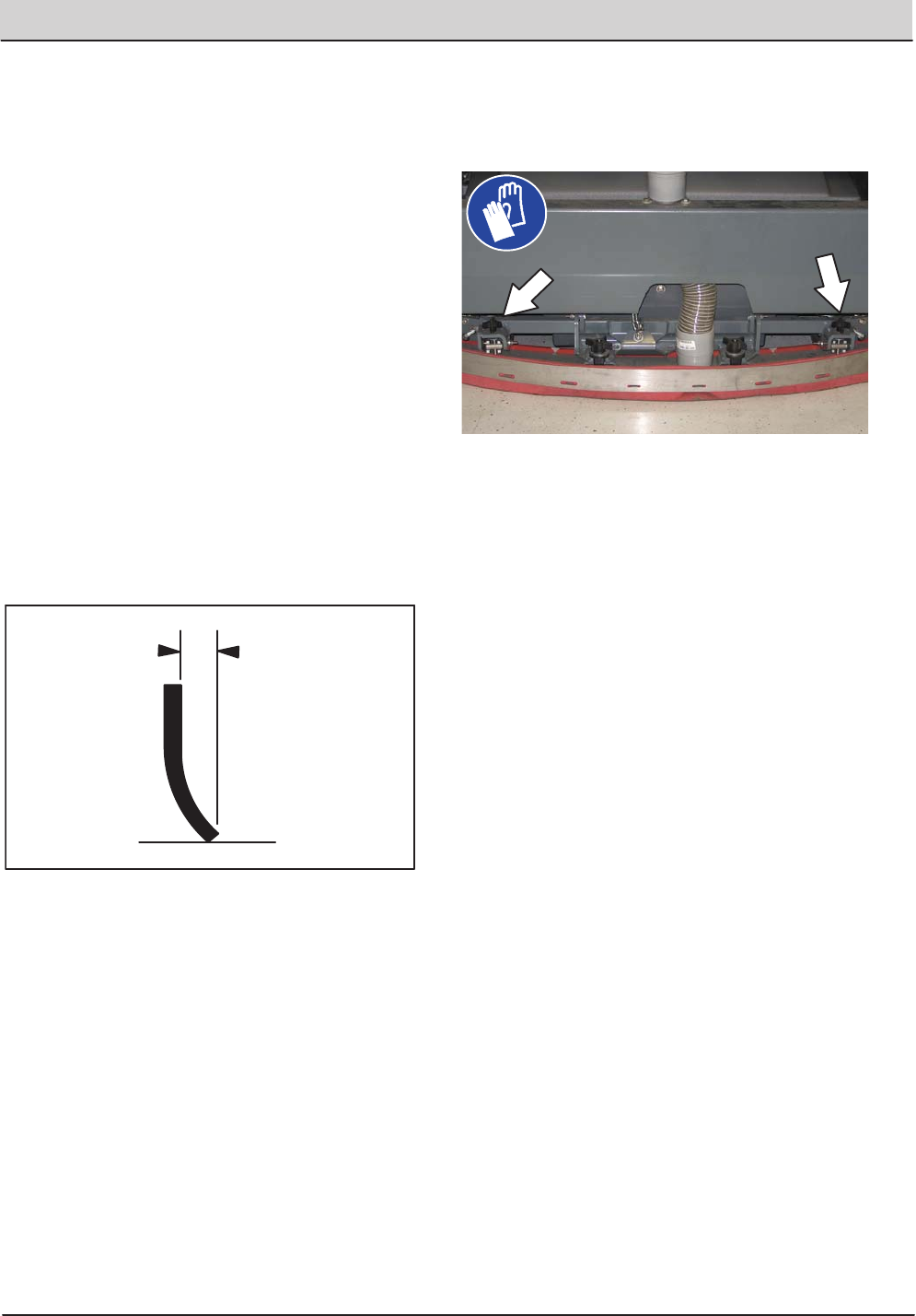
ADJUSTING THE REAR SQUEEGEE BLADE
DEFLECTION
Deflection is the amount of curl the overall
squeegee blade has when the machine moves
forward. The best deflection is when the
squeegee wipes the floor dry with a minimal
amount of deflection.
NOTE: Make sure the squeegee is level before
adjusting the deflection. See LEVELING THE
REAR SQUEEGEE.
1. Lower the squeegee and drive the machine
forward a few meters (feet).
FOR SAFETY: Before leaving or servicing
machine, stop on level surface, set parking
brake, turn off machine, and remove key.
2. Look at the amount of deflection or “curl” of
the squeegee blade. The correct amount of
deflection is 12 mm (0.50 in) for scrubbing
smooth floors and 15 mm (0.62 in) for rough
floors.
12 mm
(0.50 in)
3. To adjust the overall squeegee blade
deflection, turn the adjustment knobs
counterclockwise to increase deflection or
clockwise to decrease deflection.
4. Drive the machine forward again to recheck
the squeegee blade deflection after
adjustments are made.
5. Readjust the squeegee blade deflection if
necessary.
64 T20 Service Information (5-2017)
MAINTENANCE
MAINTENANCE
SKIRTS AND SEALS
FOR SAFETY: Before leaving or servicing
machine, stop on level surface, set parking
brake, turn off machine, and remove key.
SCRUB HEAD SKIRT
Check the skirt for damage and wear after every
100 hours of operation.
The skirts should be between 0 to 6 mm
(0 to 0.25 in) from the floor when the scrub head
is down.
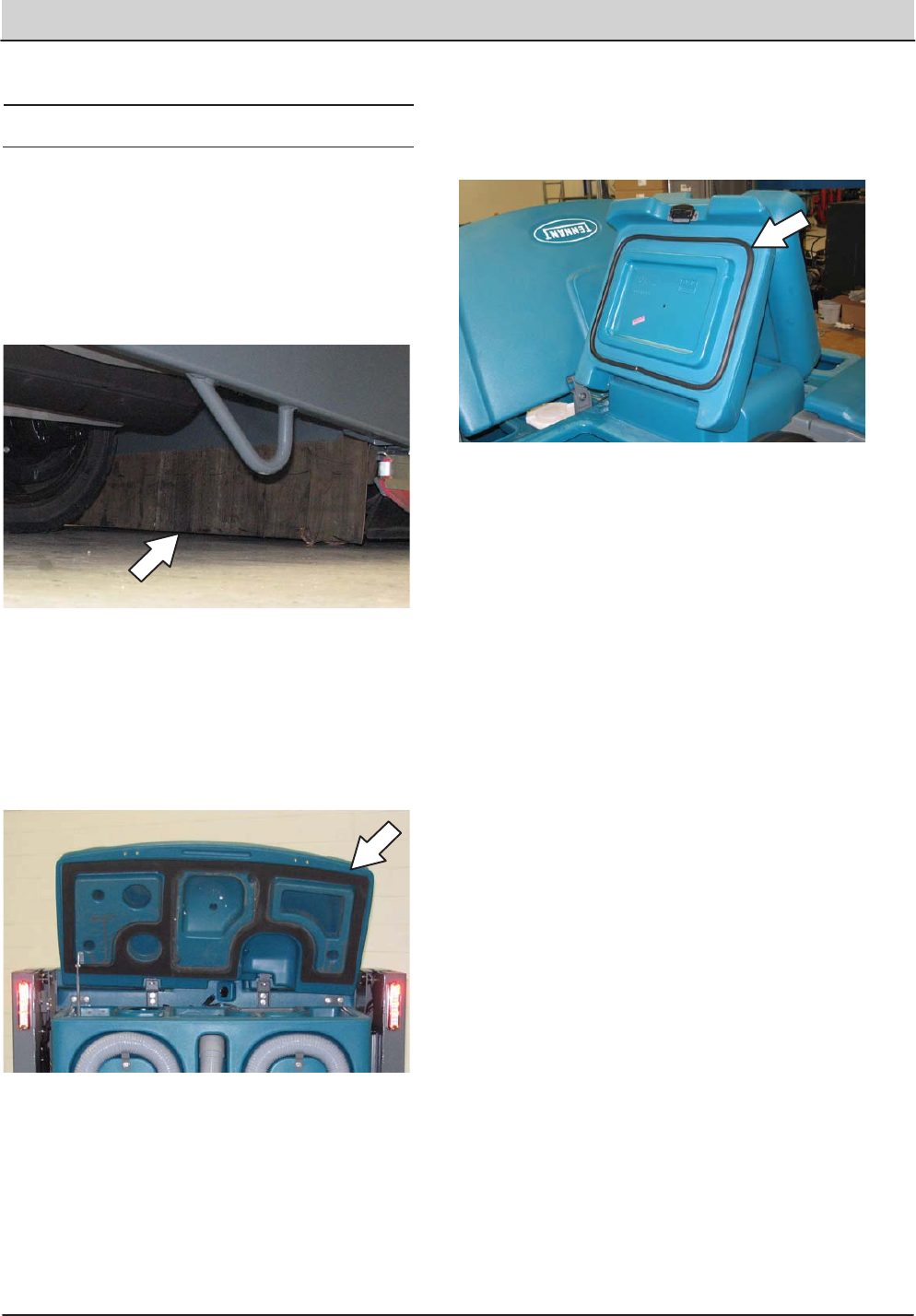
RECOVERY TANK SEAL
Check the recovery tank cover seal for damage
and wear daily.
SOLUTION TANK SEALS
Check each solution tank cover seal for damage
and wear daily.
T20 Service Information (5-2017) 65
MAINTENANCE
MAINTENANCE
BRAKES AND TIRES
BRAKES
The mechanical brakes are located on the rear
wheels. The brakes are operated by the foot
brake pedal and connecting cables.
Check the brake adjustment after every 200 hours
of operation.
To check the brake adjustment, measure the
distance from the stationary brake pedal to the
point where there is resistance in the pedal
movement. The distance must be between 6 mm
(0.25 in) and 19 mm (0.75 in). Adjust the brakes if
required.
TIRES
Check tires for damage and wear after every 100
hours of operation.
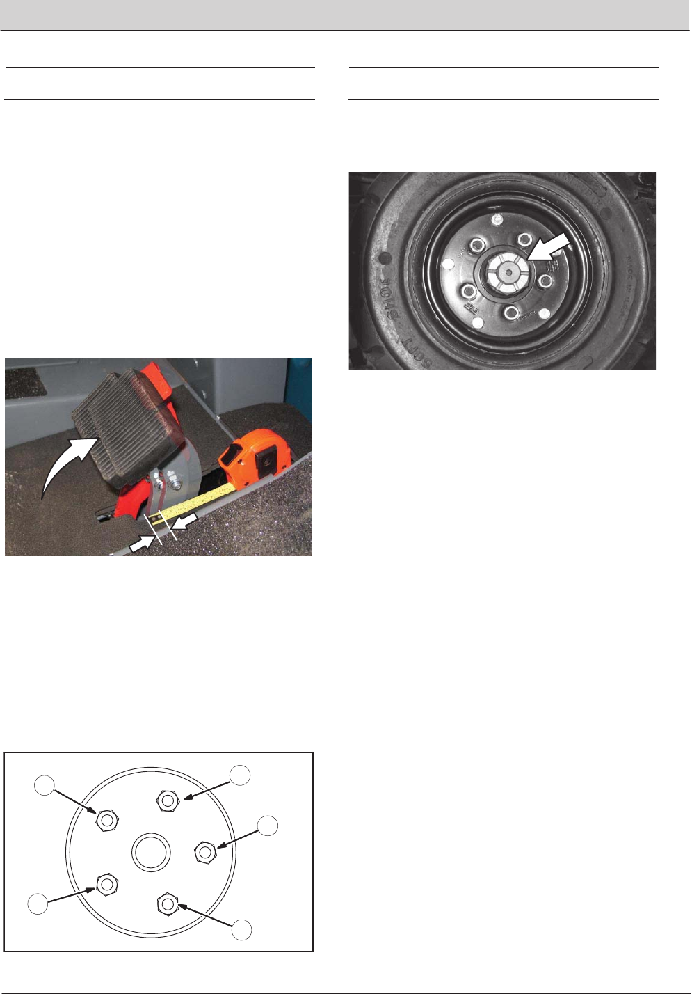
FRONT WHEEL
Torque the front wheel nuts twice in the pattern
shown to 122 to 149 Nm (90 to 110 ft lb) after the
first 50 hours of operation, and after every 800
hours there after.
2
3
4
1
5
PROPELLING MOTOR
Torque the shaft nut to 508 Nm (375 ft lb)
lubricated, 644 Nm (475 ft lb) dry, after every 800
hours of operation.
66 T20 Service Information (5-2017)
MAINTENANCE
MAINTENANCE
PUSHING, TOWING, AND TRANSPORTING
THE MACHINE
PUSHING OR TOWING THE MACHINE
If the machine becomes disabled, it can be
pushed from the front or rear, but only towed from
the front.
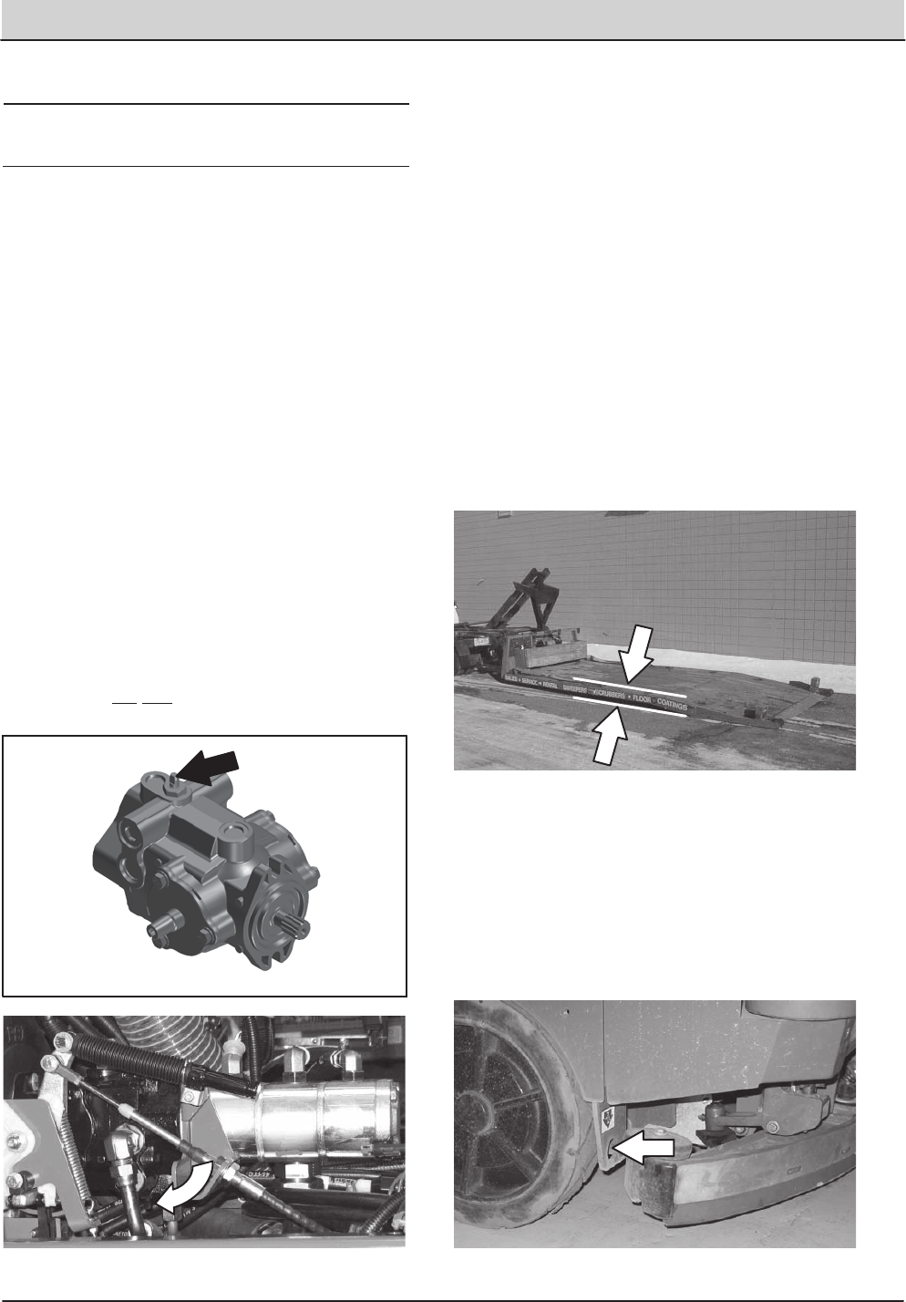
The propelling pump has a bypass valve to
prevent damage to the hydraulic system when the
machine is being pushed or towed. This valve
allows a disabled machine to be moved for a very
short distance and at a speed to not exceed 1.6
kp/h (1 mph). The machine is NOT intended to be
pushed or towed a long distance or at a high
speed.
ATTENTION! Do not push or tow machine for
a long distance or damage may occur to the
propelling system.
Turn the bypass valve located on the bottom of
the propelling pump 90 (either direction) from the
normal position before pushing or towing the
machine. Return the bypass valve back to the
normal position when through pushing or towing
the machine. Do Not use the bypass valve during
normal machine operation.
TRANSPORTING THE MACHINE
1. Raise the squeegee, scrub head, and
brushes.
FOR SAFETY: When loading machine onto
truck or trailer, drain tanks before loading
machine.
2. Position the rear of the machine at the loading
edge of the truck or trailer.
3. If the loading surface is not horizontal or is
higher than 380 mm (15 in) from the ground,
use a winch to load machine.
If the loading surface is horizontal and 380
mm (15 in) or less from the ground, the
machine may be driven onto the truck or
trailer.
FOR SAFETY: When loading machine onto
truck or trailer, use winch. Do not drive the
machine onto the truck or trailer unless the
loading surface is horizontal AND is 380 mm
(15 in) or less from the ground.
4. To winch the machine onto the truck or trailer,
attach the winching chains to the holes in the
rear jacking brackets behind the rear tires.
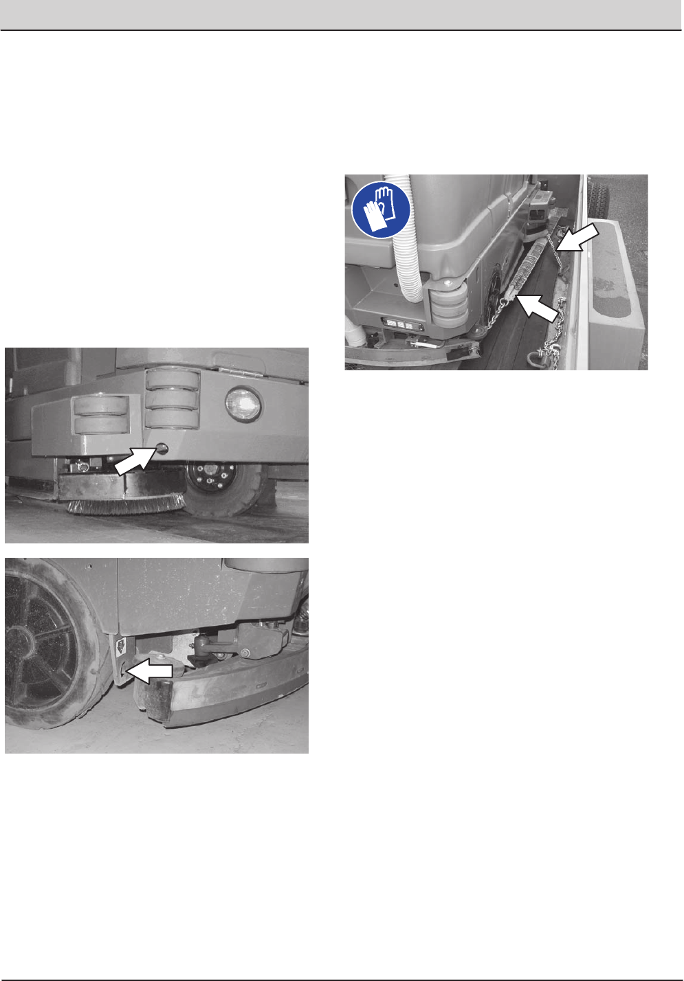
T20 Service Information (5-2017) 67
MAINTENANCE
MAINTENANCE
5. Position the machine as close to the front of
the trailer or truck as possible.
6. Set the parking brake and place a block
behind each wheel to prevent the machine
from rolling.
7. Lower the scrub head.
FOR SAFETY: When loading/unloading
machine onto/off truck or trailer, lower scrub
head and squeegee before tying down
machine.
8. Connect the tieïdown straps to the holes in
the right and left lower corners in front of the
machine and the holes in the rear jacking
brackets behind the rear tires.
9. Route the tieïdowns to the opposite ends of
the machine and hook them to the brackets
on the floor of the trailer or truck. Tighten the
tieïdown straps.
NOTE: It may be necessary to install tie-down
brackets to the floor of the trailer or truck.
10. If the loading surface is not horizontal or is
higher than 380 mm (15 in) from the ground,
use a winch to unload machine.
If the loading surface is horizontal AND is 380
mm (15 in) or less from the ground, the
machine may be driven off the truck or trailer.
FOR SAFETY: When unloading machine off
truck or trailer, use winch. Do not drive the
machine off the truck or trailer unless the
loading surface is horizontal AND 380 mm
(15 in) or less from the ground.
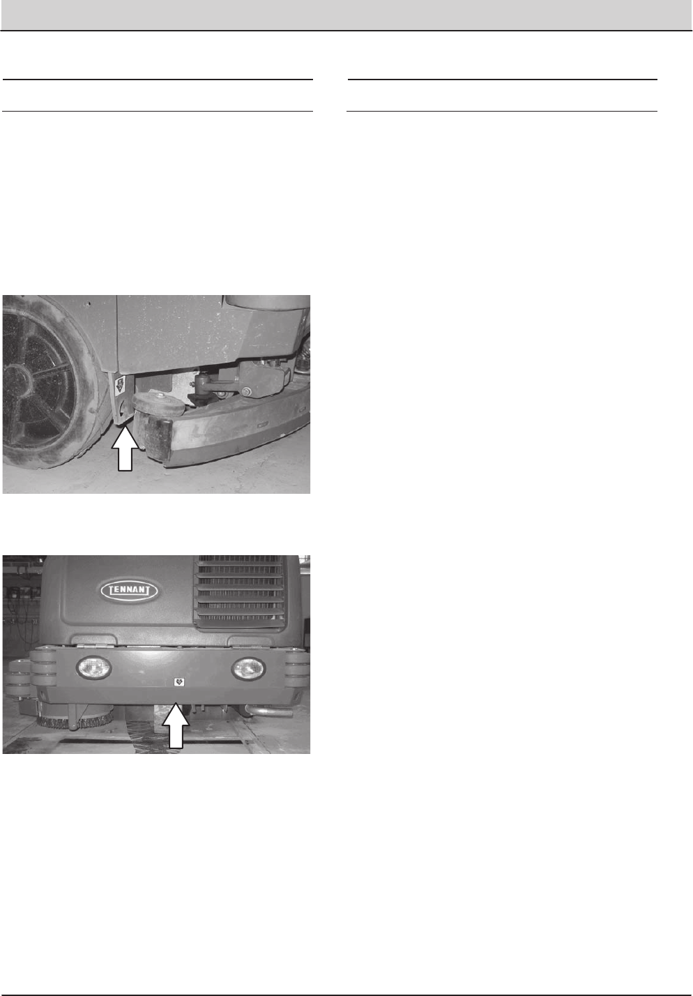
68 T20 Service Information (5-2017)
MAINTENANCE
MAINTENANCE
MACHINE JACKING
Empty the debris tray, recovery tank, and solution
tank before jacking up the machine. Jack up the
machine at the designated locations. Use a hoist
or jack capable of supporting the weight of the
machine. Use jackstands to support the machine.
Always stop the machine on a flat, level surface
and block the tires before jacking up the machine.
Rear jacking locations are located directly behind
the rear tires on each side of the machine.
Front jacking locations are located on the frame
directly in front of the front tire.
FOR SAFETY: Before leaving or servicing
machine, stop on level surface, set parking
brake, turn off machine, and remove key.
FOR SAFETY: When servicing machine, block
machine tires before jacking machine up. Use
a hoist or jack that will support the weight of
the machine. Jack machine up at designated
locations only. Support machine with jack
stands.
STORAGE INFORMATION
The following steps should be taken prior to
storing the machine for extended periods.
1. Drain and clean the solution and recovery
tanks. Open the recovery tank and solution
tank covers to allow the air to circulate.
2. Park the machine in a cool, dry area. Do not
expose the machine to rain. Store indoors.
3. Remove the battery, or charge battery every
three months.
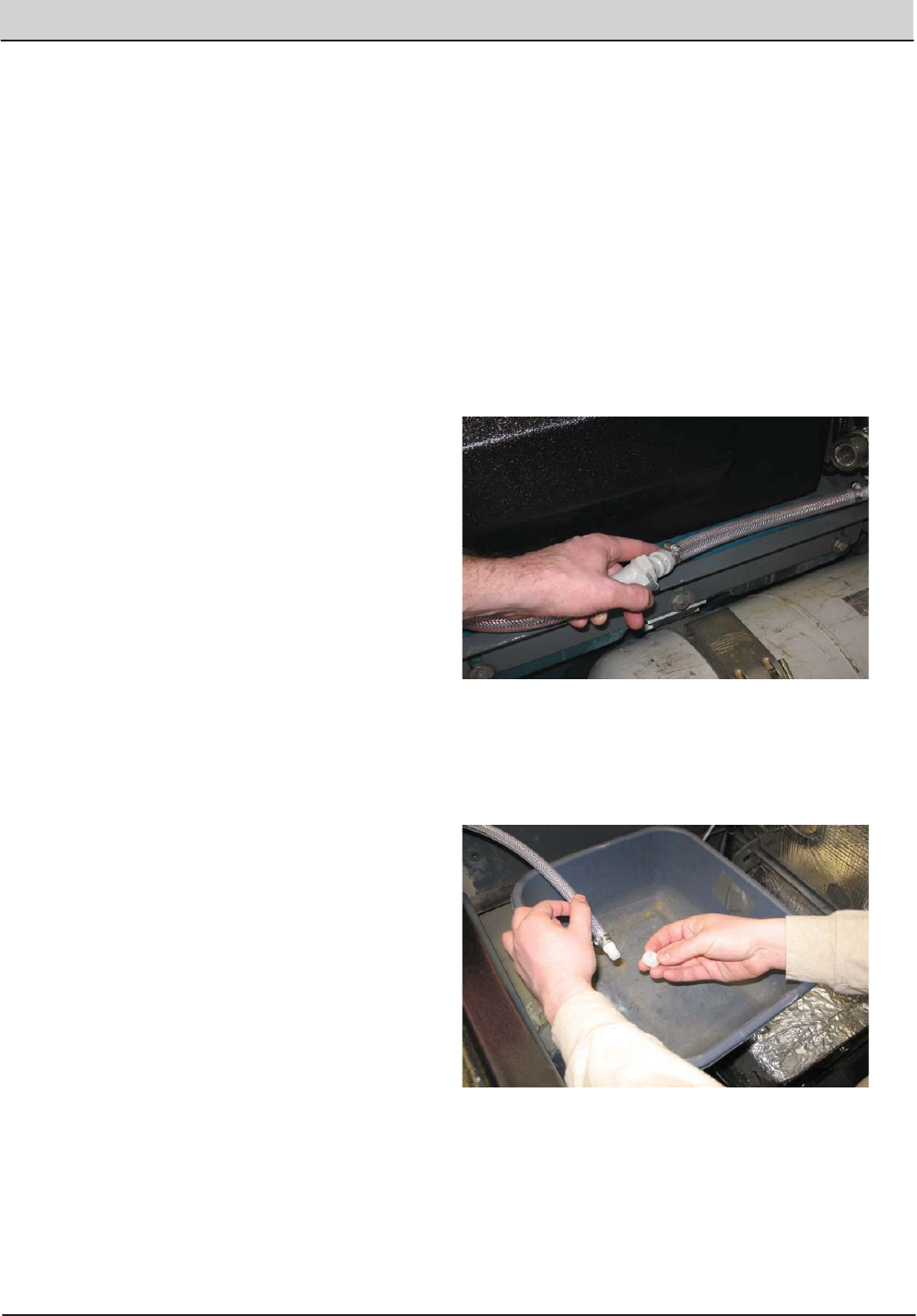
T20 Service Information (5-2017) 69
MAINTENANCE
MAINTENANCE
FREEZE PROTECTION (MACHINES WITHOUT
ecïH2O SYSTEM)
FOR SAFETY: Before leaving or servicing
machine, stop on level surface, set parking
brake, and turn off machine.
1. Be sure the solution tank and recovery tank
are empty.
2. Pour 3.8 L (1 gal) of Propylene Glycol Based /
Recreational Vehicle (RV) Antifreeze into the
solution tank.
3. Turn the key to the on position (without
starting the machine).
4. Press the scrubbing main brush button.
5. Press the 1ïSTEP button.
6. Repeatedly press the Solution increase button
(+) until the solution flow is at the highest
setting.
7. Press the directional pedal to circulate the RV
antifreeze completely through the system.
8. Press the 1ïSTEP Scrub button to turn off the
system.
9. Machines equipped with the optional
spray nozzle only: Turn on the pump until
RV antifreeze solution sprays from the nozzle.
10. Turn the key to the off position.
11. The remaining RV antifreeze does not need to
be drained from the solution tank.
NOTE: Storing or transporting machines equipped
with the ES or the FaST system in freezing
temperatures requires special procedures.
Consult a TENNANT representative for more
information.
FREEZE PROTECTION (MACHINES WITH
ecïH2O SYSTEM)
FOR SAFETY: Before leaving or servicing
machine, stop on level surface, set parking
brake, and turn off machine.
1. Empty the solution tank and recovery tank.
2. Remove the intake flush hose and from the
storage bag behind the operator seat.
3. Disconnect the ecïH2O system intake hose
from the solution supply hose and connect the
intake flush hose (gray connector) to the
ecïH2O system intake hose.
4. Pull the drain tube from the between the
ecïH2O unit and the operator compartment,
remove the cap from the tube, and place the
end of the tube into an empty container. Set
the cap aside.
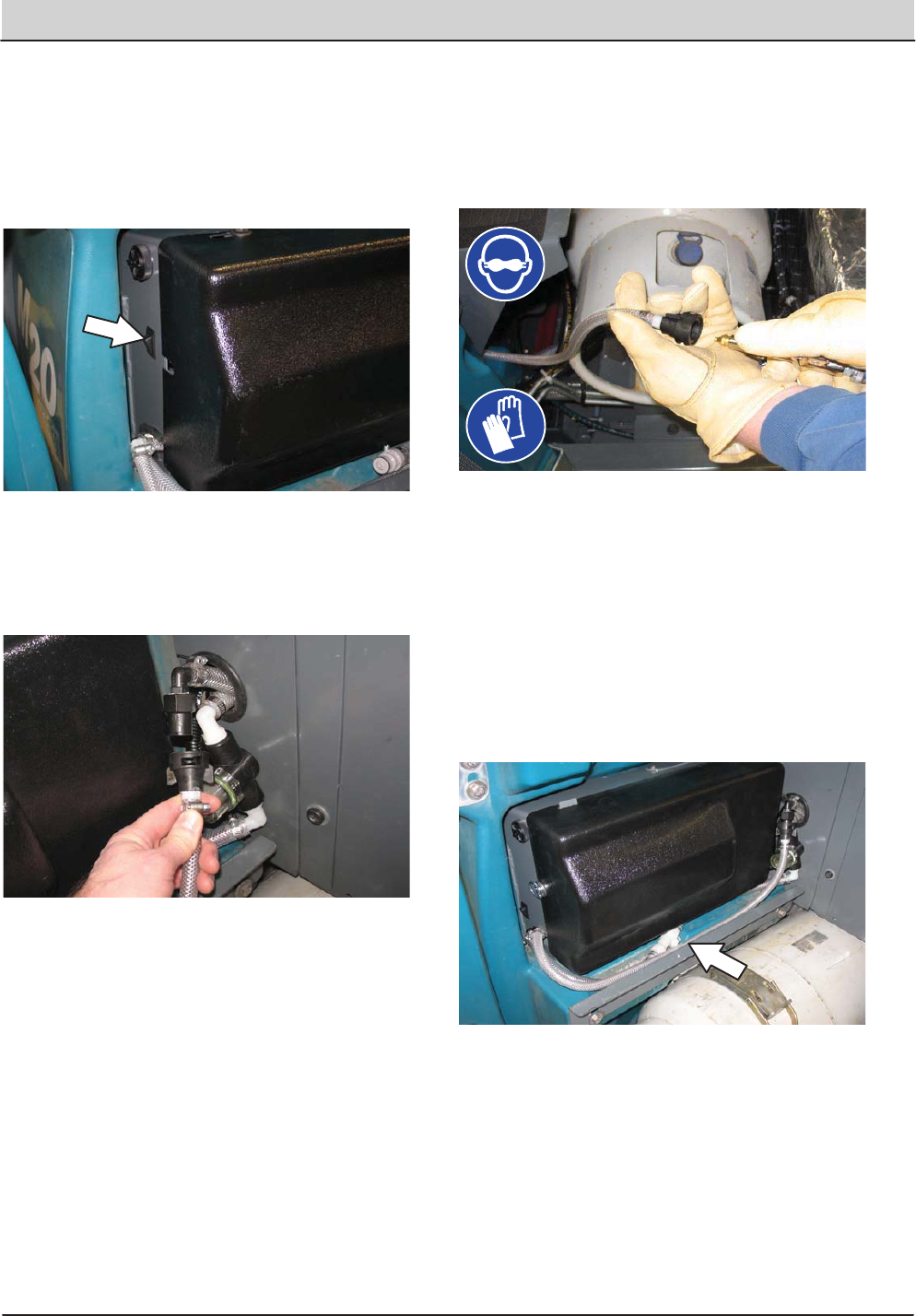
70 T20 Service Information (5-2017)
MAINTENANCE
MAINTENANCE
5. Turn the key to the on position (without
starting the machine).
6. Press and release the ecïH2O module flush
switch. Allow the system to drain water into
the container for 2 minutes.
7. Press the ecïH2O module flush switch to
shut off the system.
8. Disconnect the ecïH2O system outlet hose
from the hose to the scrub head.
9. Blow pressurized air (less than 344 kPa (50
psi)) into the ecïH2O system outlet hose.
Continue blowing compressed air into the
outlet hose until water no longer drains from
the drain tube
10. Reinstall the cap onto the drain tube and
insert the tube back between the ecïH2O
module and the operator compartment.
11. Reconnect the ecïH2O system intake hose to
the solution supply hose and the ecïH2O
system outlet hose to the hose to the scrub
head.
12. Insert the intake and outlet hoses down
between the ecïH2O assembly and the
bracket.
13. Return the intake flush hose to the storage
bag behind the operator seat.
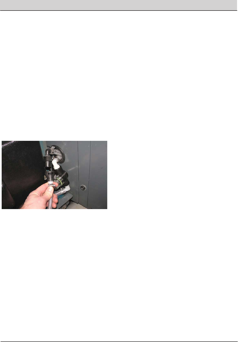
T20 Service Information (5-2017) 71
MAINTENANCE
MAINTENANCE
PRIMING THE ecïH2O SYSTEM
Prime the ecïH2O system if the machine has
been stored for a long period without water in the
solution tank / ecïH2O system.
FOR SAFETY: Before leaving or servicing
machine, stop on level surface, set parking
brake, and turn off machine.
1. Fill the solution tank with clean cool water.
See FILLING THE SOLUTION TANK section
of this manual.
2. Remove the outlet flush hose (black
connector) from the storage bag behind the
operator seat.
3. Disconnect the ecïH2O system outlet hose
from the hose to the scrub head and connect
the outlet flush hose to the ecïH2O system
outlet hose.
4. Place the ecïH2O system outlet hose into an
empty container.
5. Turn the key to the on position (without
starting the machine).
6. Press and release the ecïH2O module flush
switch. Allow the system to drain water into
the container for 2 minutes.
7. Press the ecïH2O module flush switch to
shut off the system.
8. Disconnect the outlet flush hose from the
ecïH2O system outlet hose and return the
flush hose to the storage bag.
9. Reconnect the ecïH2O system outlet hose to
the hose to the scrub head.

72 T20 Service Information (5-2017)
ELECTRICAL TROUBLESHOOTING
ELECTRICAL TROUBLESHOOTING
T20
ELECTRICAL
Troubleshooting Information
NOTE: Troubleshooting charts may be shown with optional equipment.
The optional equipment may not be specified in these charts. Some
machines may not be equipped with all components shown.
BEFORE CONDUCTING TESTS:
*Read and Follow ALL Safety Warnings and Precautions as
mentioned at the beginning of this manual.
*Always use an ESD (Electrostatic Discharge) strap when working near the
Control Board.
*Be cautious when working near Control Board – Battery voltage is always
present, even with Key OFF.
*Always dis-connect Battery when removing or replacing components.
* Call Technical Services if Diagnostic Time Exceeds One Hour With
Unknown Cause or Course of Action.
E
DURING TESTS:
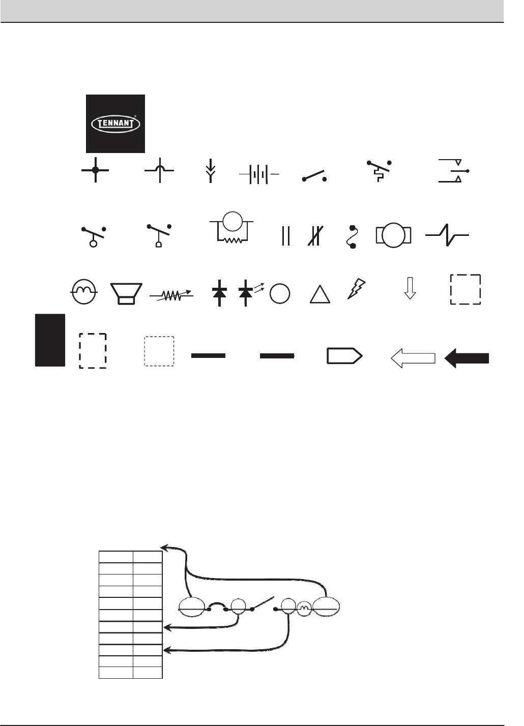
T20 Service Information (5-2017) 73
ELECTRICAL TROUBLESHOOTING
Terms & Abbreviations
Example of Wiring Numbers & Colors:
Wiring Color Codes
(Unless otherwise marked)
Right Most Digit
of WireNumber
Color of Wire
0 Tan
1 Pink
2 Brown
3 Orange
4 Yellow
5 Green
6 Blue
7 Purple
8 Gray
9 White
1 RED 25 7 13 BLK
Fuse Motor Solenoid
Valve
Horn or
Alarm
Together
Movement from
Normal Position
Component in Position
Other than Normal
Battery Positive
or Positive Output
Battery Negative
or Logic Ground
Open Closed
Relay Contacts
Diode LED Information
!
Warning! Component
is Energized
Information
Box
Assembly
Lamp
(Light Bulb)
M2A
Relay Coil with spike
suppression resistor
Normally Open Normally Open
Liquid Level Switch Pressure Switch
Sensor
(Variable Resistor)
Connection TO or
FROM Another Point
PIN P2-11 PIN P2-35
Control
Board Input
Control
Board Output
+-
OFF
Wires Connected Wires Not Plug-in Battery Normally Open Normally Open Normally Open
Together Connected Connection Switch Temperature Switch Momentary Switch
i
ECM– EngineControlModule
LED– LightEmittingDiode
MIL– MalfunctionIndicatorLamp
PWM– PulseWidthModulation(Amethodofusingcontrolledon/off
timestoregulatethevoltageandcurrentsuppliedtoanelectricaldevice)
SV– SolenoidValve
SW– Switch
E
Schematic Symbols Used In This Manual
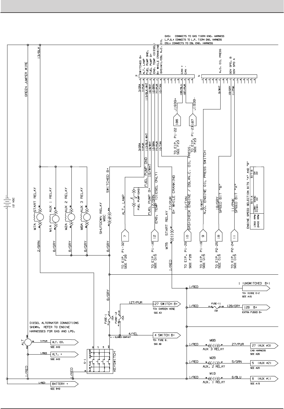
74 T20 Service Information (5-2017)
ELECTRICAL TROUBLESHOOTING
MACHINE ELECTRICAL SCHEMATIC
STANDARD PARTS
T20 Gas/LPG 9016201 (12−2016)
2‐124
Fig. 61 − Electrical Schematic
1
2
3
1075421 − 356681 − T20
Home
Find...
Go To..
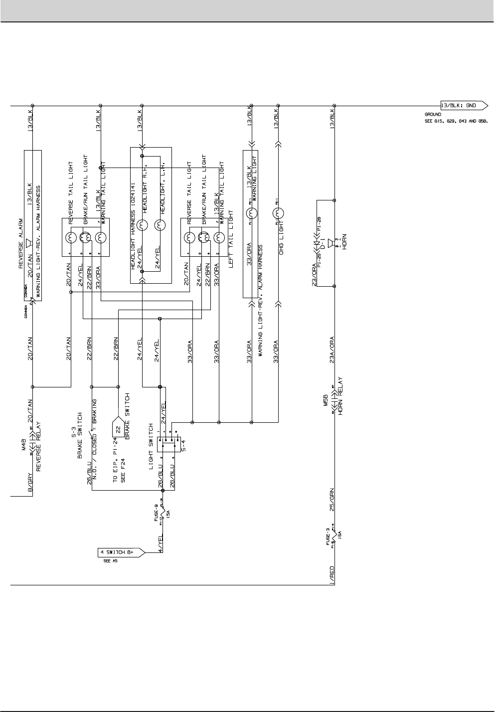
T20 Service Information (5-2017) 75
ELECTRICAL TROUBLESHOOTING
MACHINE ELECTRICAL SCHEMATIC (CONTINUED)
STANDARD PARTS
2‐125
T20 Gas/LPG 9016201 (8−2016)
Fig. 61 − Electrical Schematic
1
2
3
1075421 − 356681 − T20
Home
Find...
Go To..
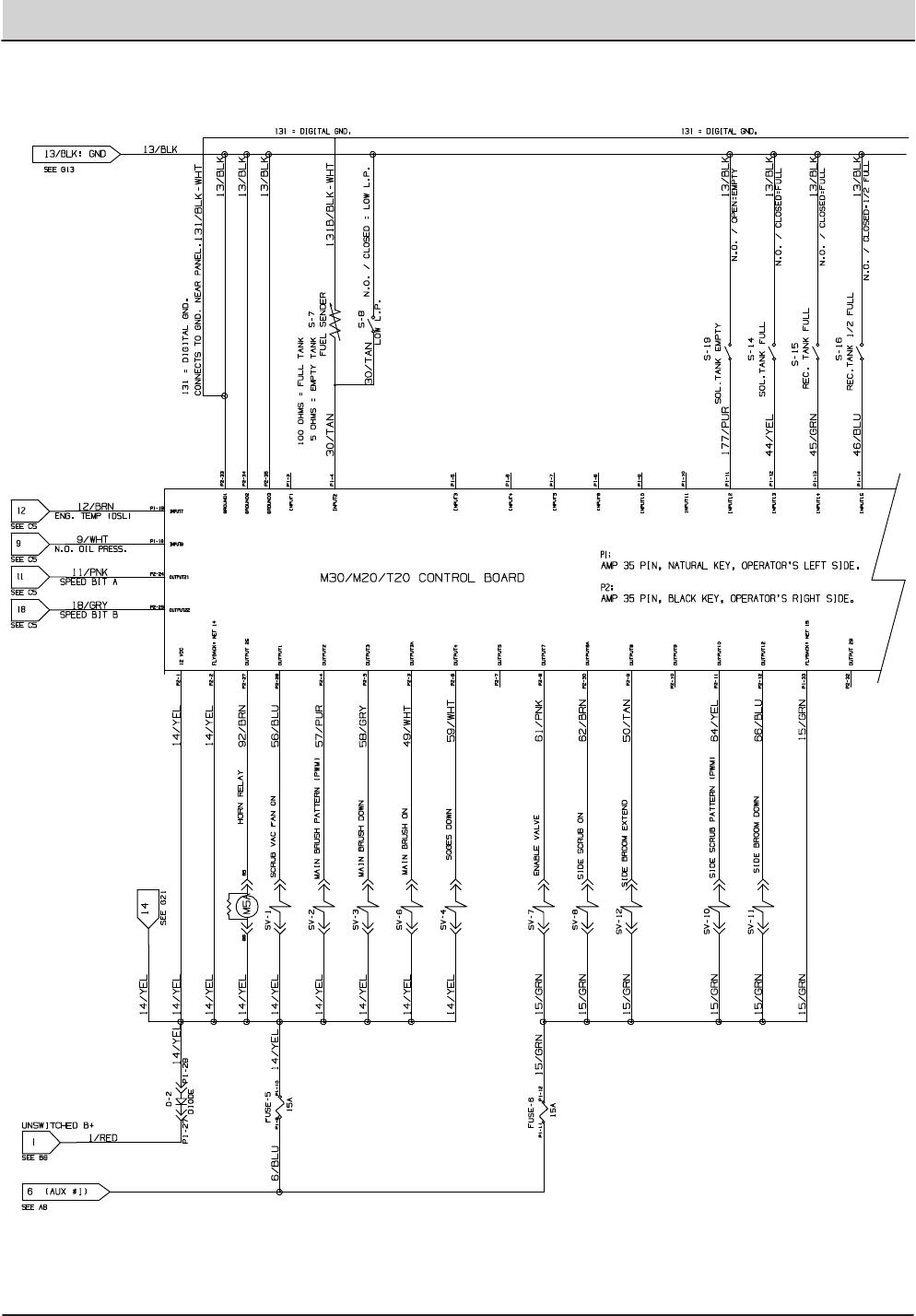
76 T20 Service Information (5-2017)
ELECTRICAL TROUBLESHOOTING
MACHINE ELECTRICAL SCHEMATIC (CONTINUED)
STANDARD PARTS
T20 Gas/LPG 9016201 (8−2016)
2‐126
Fig. 61 − Electrical Schematic
4
5
1075421 − 356681 − T20
Home
Find...
Go To..
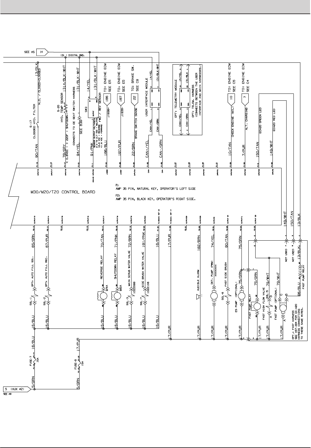
T20 Service Information (5-2017) 77
ELECTRICAL TROUBLESHOOTING
MACHINE ELECTRICAL SCHEMATIC (CONTINUED)
STANDARD PARTS
2‐127
T20 Gas/LPG 9016201 (8−2016)
Fig. 61 − Electrical Schematic
4
5
1075421 − 356681 − T20
Home
Find...
Go To..
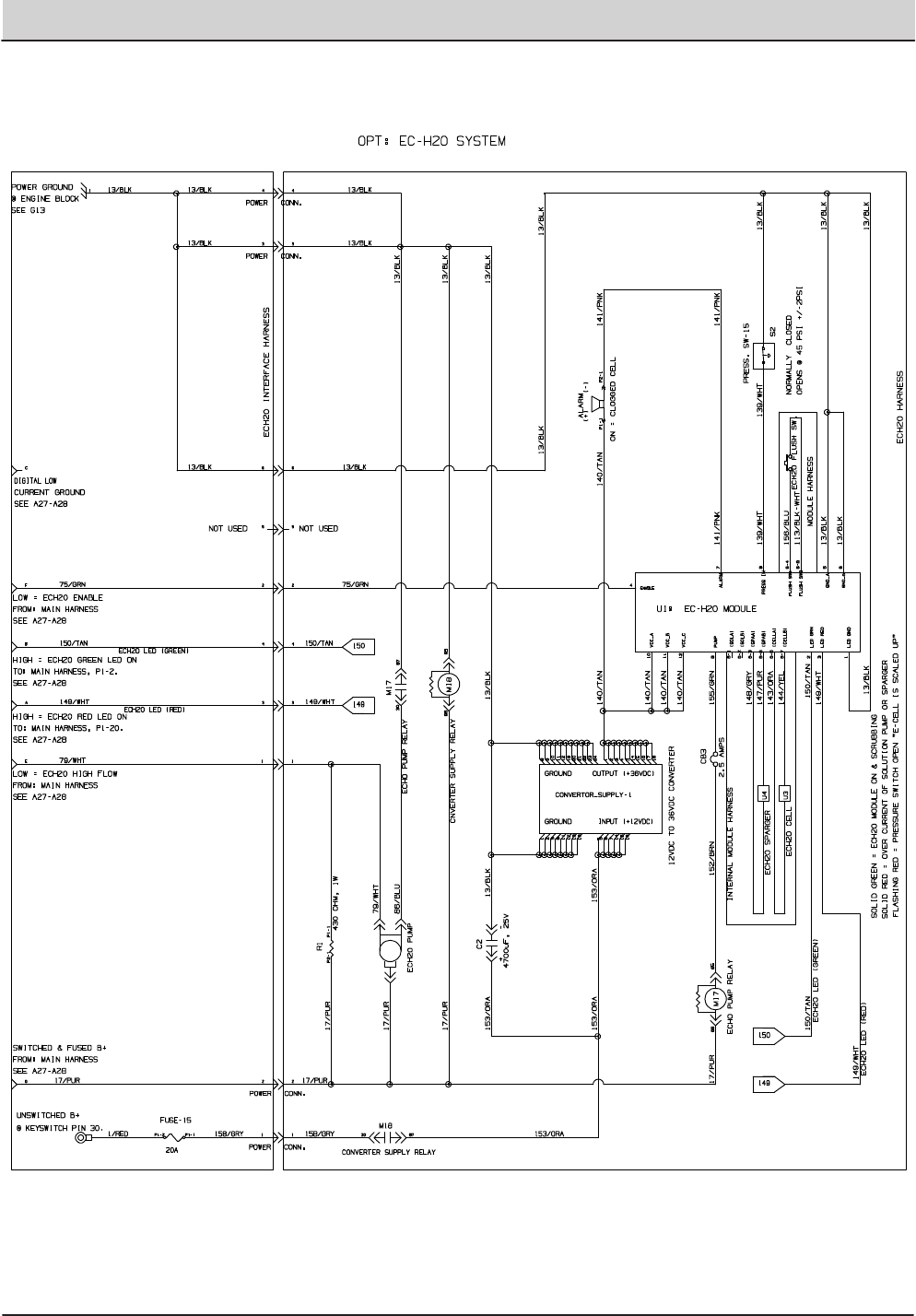
78 T20 Service Information (5-2017)
ELECTRICAL TROUBLESHOOTING
MACHINE ELECTRICAL SCHEMATIC (CONTINUED)
STANDARD PARTS
T20 Gas/LPG 9016201 (8−2016)
2‐128
Fig. 61 − Electrical Schematic
1075421 − 356681 − T20
Home
Find...
Go To..
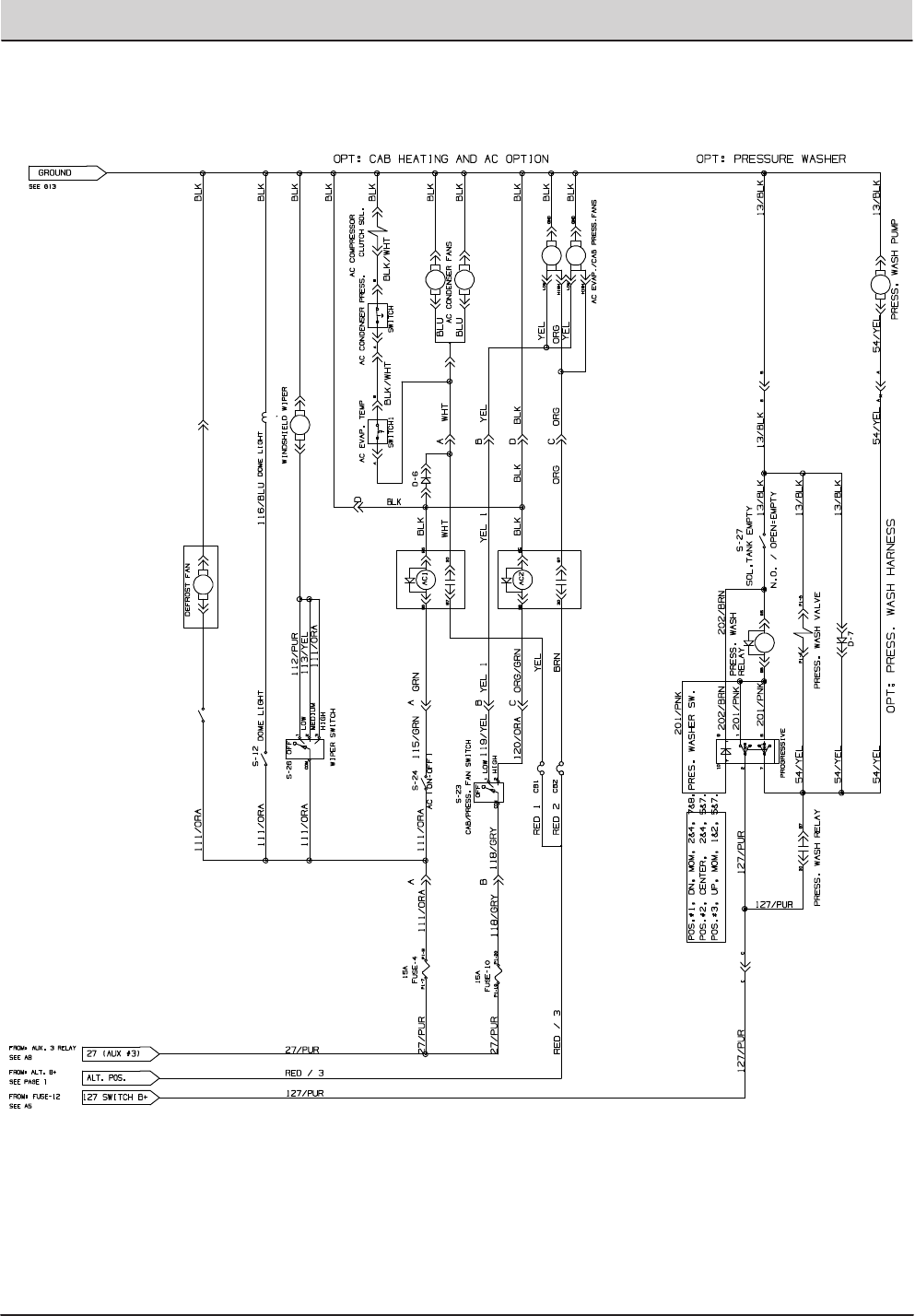
T20 Service Information (5-2017) 79
ELECTRICAL TROUBLESHOOTING
MACHINE ELECTRICAL SCHEMATIC (CONTINUED)
STANDARD PARTS
2‐129
T20 Gas/LPG 9016201 (8−2016)
Fig. 61 − Electrical Schematic
1075420 − 356680
Home
Find...
Go To..
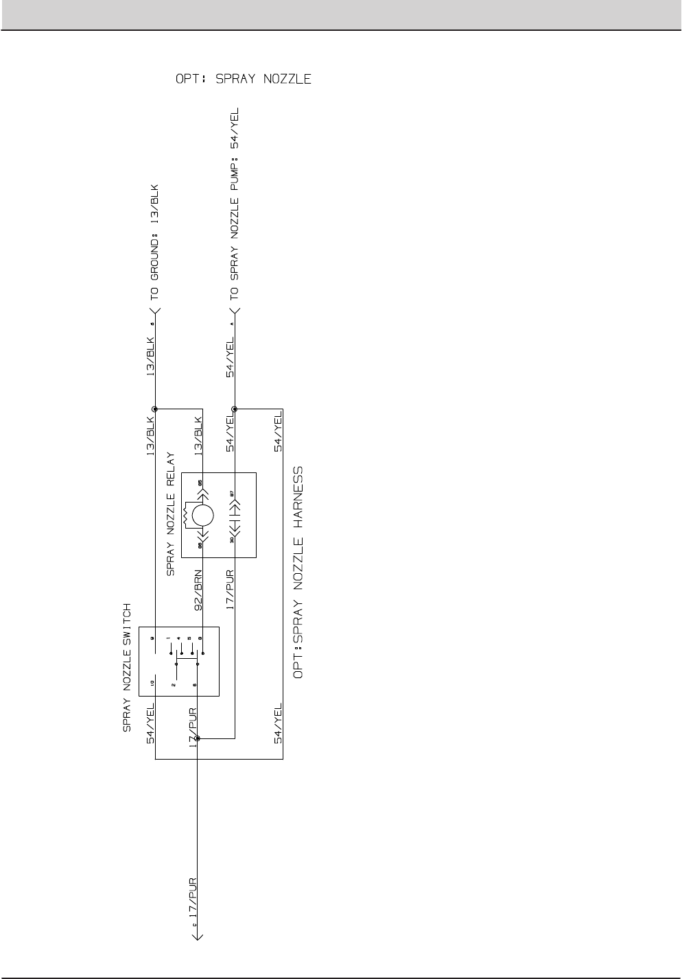
80 T20 Service Information (5-2017)
ELECTRICAL TROUBLESHOOTING
MACHINE ELECTRICAL SCHEMATIC (CONTINUED)
STANDARD PARTS
T20 Gas/LPG 9016201 (8−2016)
2‐130
Fig. 61 − Mitsubishi Electrical Schematic
1075421 − 356681 − T20
Home
Find...
Go To..
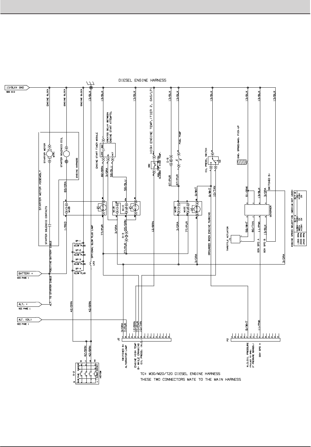
T20 Service Information (5-2017) 81
ELECTRICAL TROUBLESHOOTING
DIESEL ENGINE HARNESS ELECTRICAL SCHEMATIC
STANDARD PARTS
T20 Diesel 9016251 (8−2016)
2‐120
Fig. 57 − Electrical Schematic
1075420 − 356680
Go To..
Home
Find...
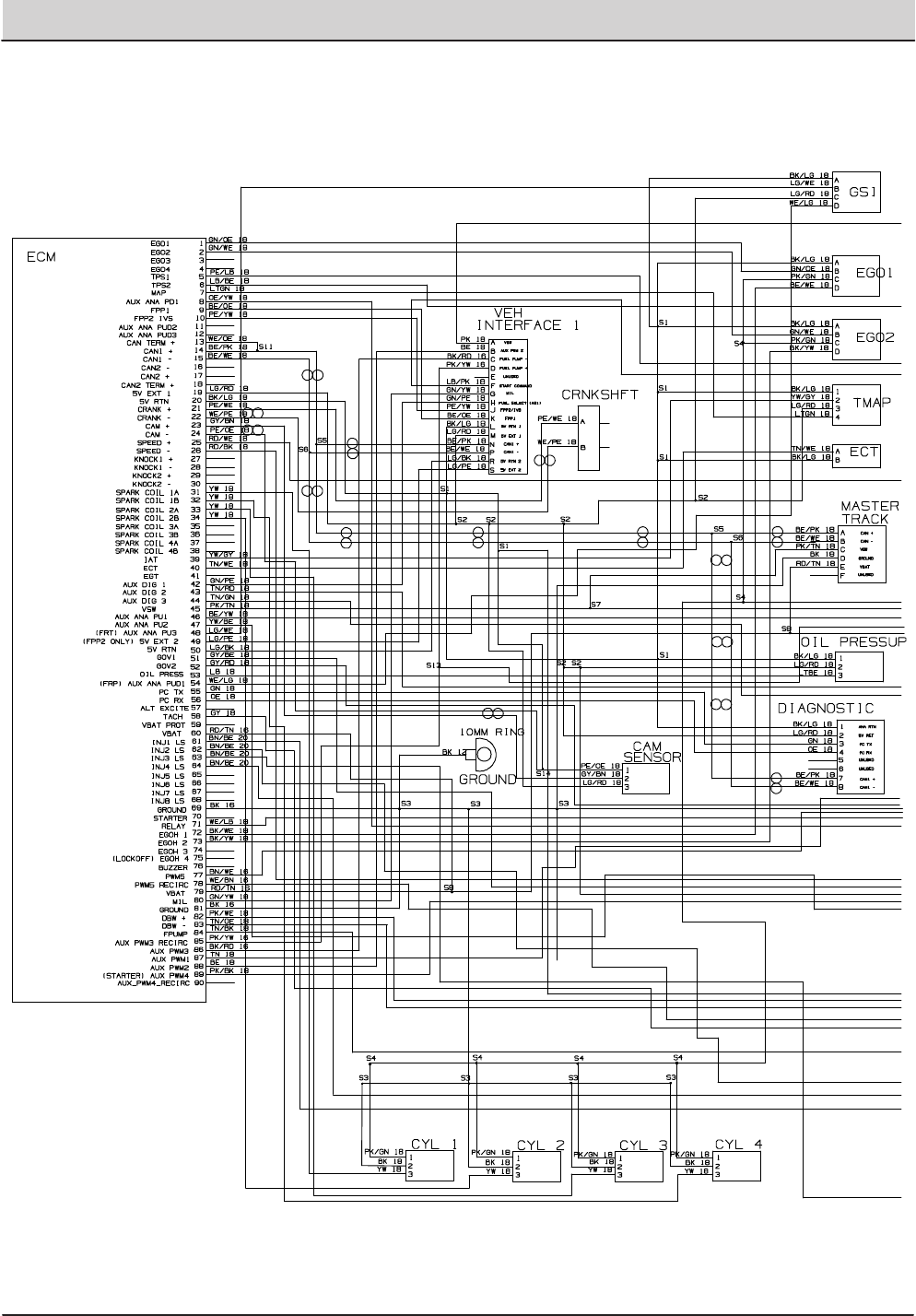
82 T20 Service Information (5-2017)
ELECTRICAL TROUBLESHOOTING
GAS ENGINE HARNESS ELECTRICAL SCHEMATIC (MITSUBISHI)
STANDARD PARTS
T20 Gas/LPG 9016201 (8−2016)
2‐132
Fig. 62 − Mitsubishi Electrical Schematic, Gas Engine Harness
1071653− 356303
Home
Find...
Go To..
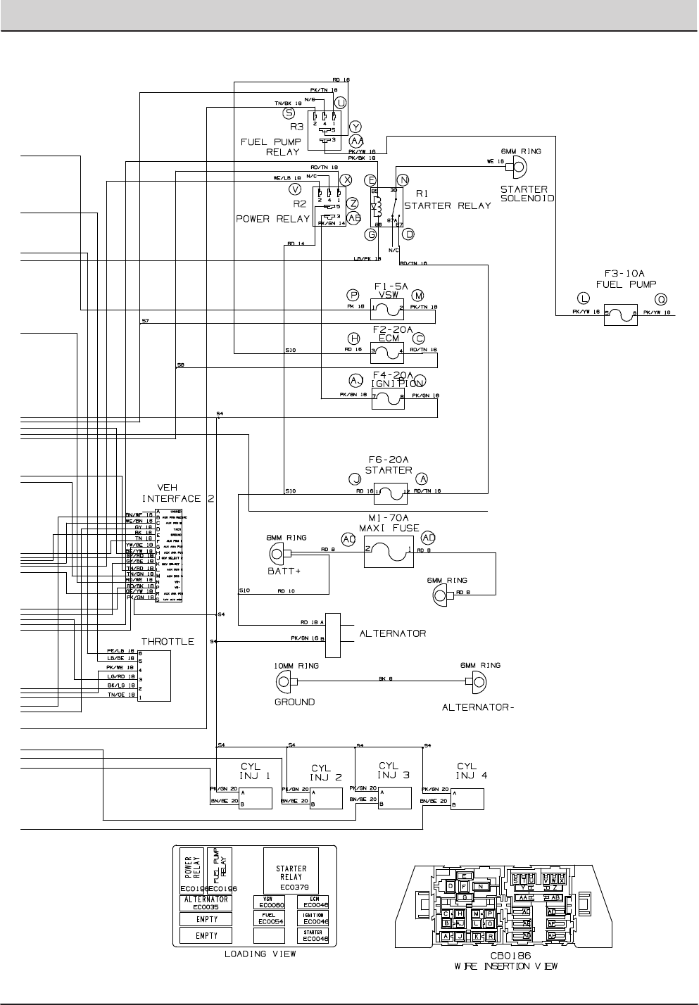
T20 Service Information (5-2017) 83
ELECTRICAL TROUBLESHOOTING
GAS ENGINE HARNESS ELECTRICAL SCHEMATIC (MITSUBISHI) (CONTINUED)
STANDARD PARTS
2‐133
T20 Gas/LPG 9016201 (8−2016)
Fig. 62 − Mitsubishi Electrical Schematic, Gas Engine Harness
1071653− 356303
Home
Find...
Go To..
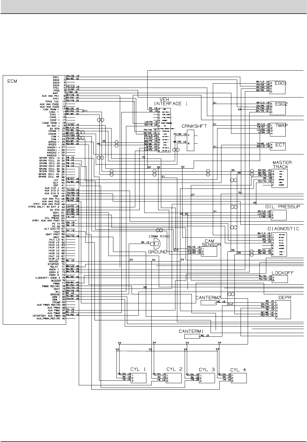
84 T20 Service Information (5-2017)
ELECTRICAL TROUBLESHOOTING
LPG ENGINE HARNESS ELECTRICAL SCHEMATIC (MITSUBISHI)
STANDARD PARTS
T20 Gas/LPG 9016201 (8−2016)
2‐134
Fig. 63 − Mitsubishi Electrical Schematic, LPG Engine Harness
1071654− 356304
Home
Find...
Go To..
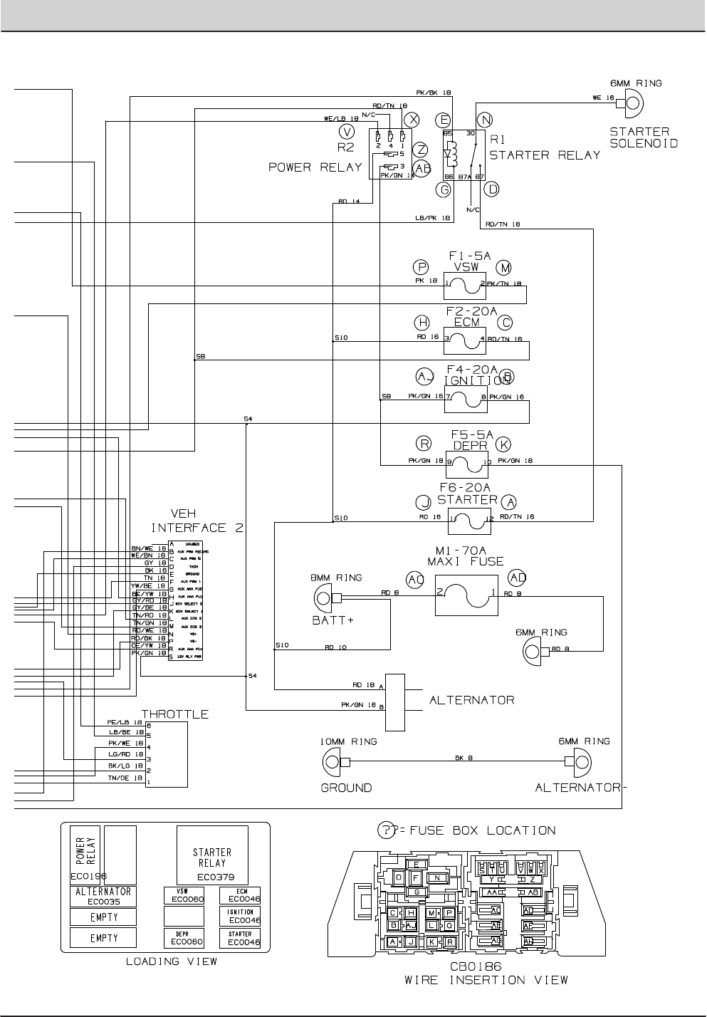
T20 Service Information (5-2017) 85
ELECTRICAL TROUBLESHOOTING
LPG ENGINE HARNESS ELECTRICAL SCHEMATIC (MITSUBISHI) (CONTINUED)
STANDARD PARTS
2‐135
T20 Gas/LPG 9016201 (8−2016)
Fig. 63 − Mitsubishi Electrical Schematic, LPG Engine Harness
1071654− 356304
Home
Find...
Go To..

86 T20 Service Information (5-2017)
ELECTRICAL TROUBLESHOOTING
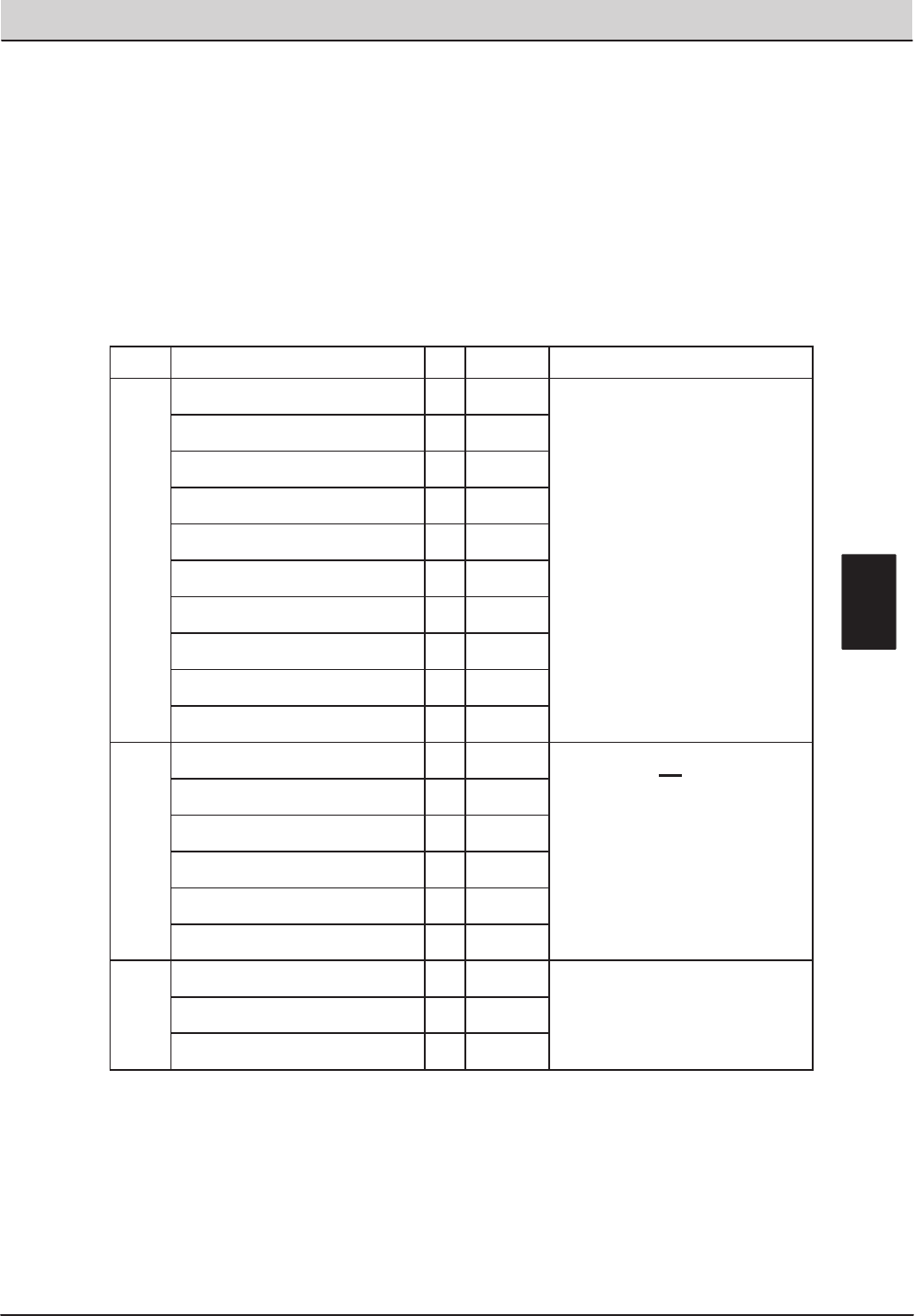
T20 Service Information (5-2017) 87
ELECTRICAL TROUBLESHOOTING
E = Electrical Component
H = Hydraulic Component
The following chart lists various options and the electrical and/or hydraulic components
that are associated with the option. Refer to the “notes” section for any components that
are deleted from a standard machine in order to have the installed option.
Hose
option added components E or H component # notes
Side Brush
Side Brush ON Solenoid Valve E,H SV-8
Side Brush Pressure Solenoid Valve E,H SV-10
Side Brush Down Solenoid Valve E,H SV-11
Side Brush Extend Solenoid Valve E,H SV-12
FaST Side Brush Valve ESOL-6
Side Brush Water Valve ESOL-7
Side Brush Manifold Hx
Side Brush Lift Cylinder Hx
Side Brush Extend Cylinder Hx
Side Brush Motor Hx
ES
(Extended Scrub)
Solution Tank Auto Fill Water Valve ESOL-1 If machine has ES option, the following
components will not be on the
machine: FaST Water Pump, FaST
Water Pump Relay (M11), FaST
Detergent Pump, FaST Air Pump,
FaST Enable Valve (SOL-4), FaST
High Flow Valve (SOL-5), FaST Side
Brush Valve (SOL-6)
Recovery Tank Auto Fill Water Valve ESOL-2
Solution Tank Full Switch ES-14
Recovery Tank Half Full Switch ES-16
Detergent Pump Ex
ES Pump Ex
Spray
Spray Hose Pump Ex
Spray Hose Relay EM12
Spray Hose Switch ES-25
E
T20 Option Components
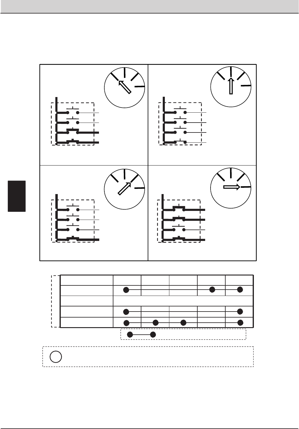
88 T20 Service Information (5-2017)
ELECTRICAL TROUBLESHOOTING
ACC
RUN
START
NO CONNECTIONSOFF
GLOW PLUG
SWITCH TERMINAL MARKING
50 17 19
30
KEY SWITCH POSITION
Common connections in various switch positions should be less than
one (1) ohm resistance.
“ . “ Indicates a common connection
E
30
50
17
19
ACC
30
50
17
19
ACC
30
50
17
19
ACC
RunPosition StartPosition
SpringLoaded‐Returnsto“RUN”UnlessHeld
30
50
17
19
ACC
OffPosition
GlowPlugPosition(DieselOnly)
SpringLoaded– Returnsto“Off”UnlessHeld
KeySwitch
Glow
Plug
Off Run
Start
KeySwitch
Glow
Plug
Off Run
Start
KeySwitch
Glow
Plug
Off Run
Start
KeySwitch
Glow
Plug
Off Run
Start
i
T20 Key Switch
Conditions: Glow Plug, Key Off, Run, Start Positions
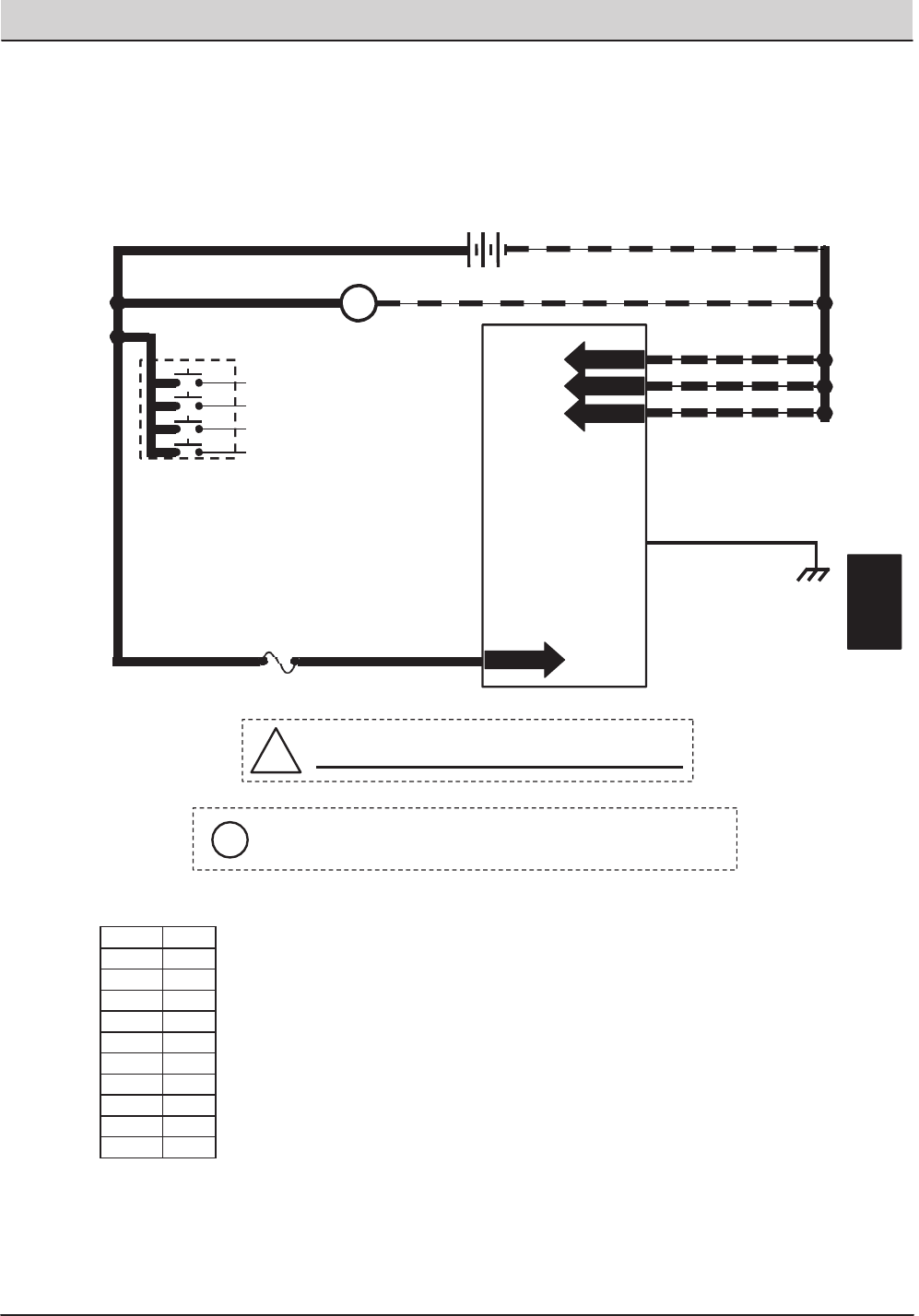
T20 Service Information (5-2017) 89
ELECTRICAL TROUBLESHOOTING
T20 Key OFF Power Distribution
Conditions: Key off
81
1/RED 13/BLK
13/BLK
13/BLK
13/BLK
+-
12 VDC
ALTERNATOR
+-
1/RED
Touch Panel / Control Board
FUSE 10
15 AMP
GREEN JUMPER WIRE1/RED
1/RED 81
Wiring Color Codes
(Unless otherwise marked)
!Be cautious when working near Control Board -
Battery voltage is always present, even with Key OFF
PIN P2-33
PIN P2-34
PIN P2-35
PIN P2-3
PIN P1-23
STATIC
GROUND
105
KEY SWITCH
OFF
Right Most Digit
of Wir e N umber
Color of Wire
0 Tan
1 Pink
2 Brown
3 Orange
4 Yellow
5 Green
6 Blue
7 Purple
8 Gray
9 White
E
30
50
17
19
ACC
Pin P2-3 supplies power to the on-board clock only.
Disconnecting battery, removing Fuse 10, or removing connector
P2 from Control Board will require the clock to be reset.
i
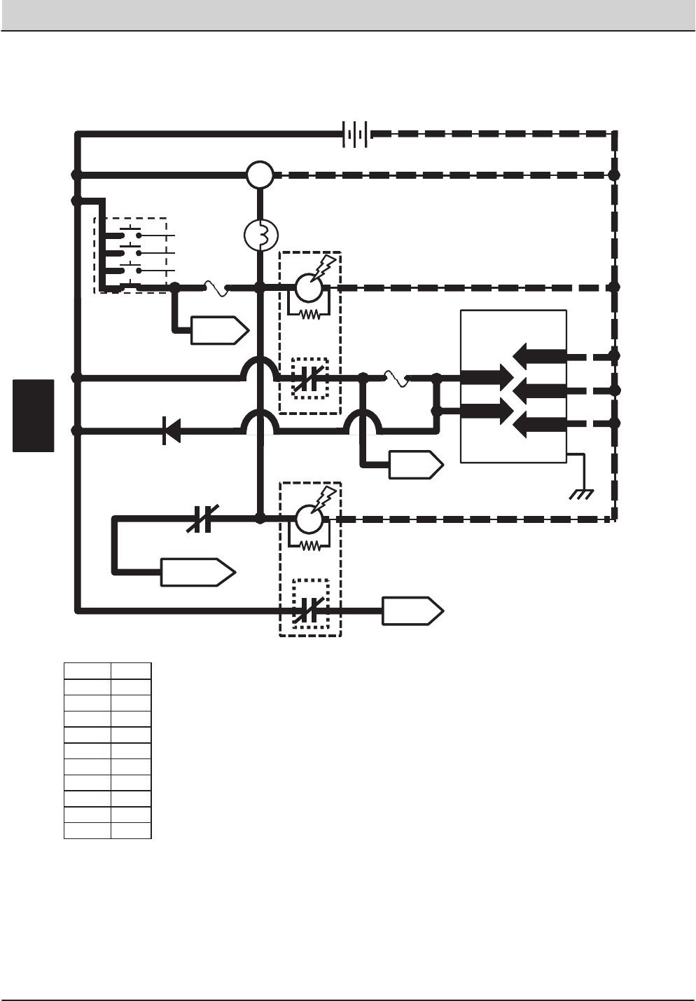
90 T20 Service Information (5-2017)
ELECTRICAL TROUBLESHOOTING
13/BLK
TO ENGINE
HARNESS
PIN P2-35
PIN P1-23
STATIC
GROUND
105
Wiring Color Codes
(Unless otherwise marked)
TO FUSES
7&8
SHUTDOWN RELAY
CONTACTS
(Normally CLOSED)
3
8
8
M2A
M6C
TO FUSE
6
1/RED 5
1/RED 30
3
8 86
6
85 13/BLK
M2B
AUX. 2
RELAY
87
14
T20 Key ON Power Distribution
Conditions: Key on, engine off
1/RED 13/BLK
13/BLK
13/BLK
+-
12 VDC
KEY SWITCH
RUN
ALTERNATOR
+-
Touch Panel /
Control Board
GREEN JUMPER WIRE1/RED
1/RED
FUSE 5
15 AMP
4
1/RED1/RED 6
PIN P2-33
PIN P2-34
813/BLK
13/BLK
14
FUSE 1
15 AMP
PIN P2-1
PIN P2-2
ALTERNATOR
LAMP
M1B
AUX. 1
RELAY
M1A
7
8
14
13/BLK
86 85
30 87
4
D-2
14 14
TO FUSES
9 &12
1/RED
Right Most Digit
of Wir e N umber
Color of Wire
0 Tan
1 Pink
2 Brown
3 Orange
4 Yellow
5 Green
6 Blue
7 Purple
8 Gray
9 White
E
30
50
17
19
ACC
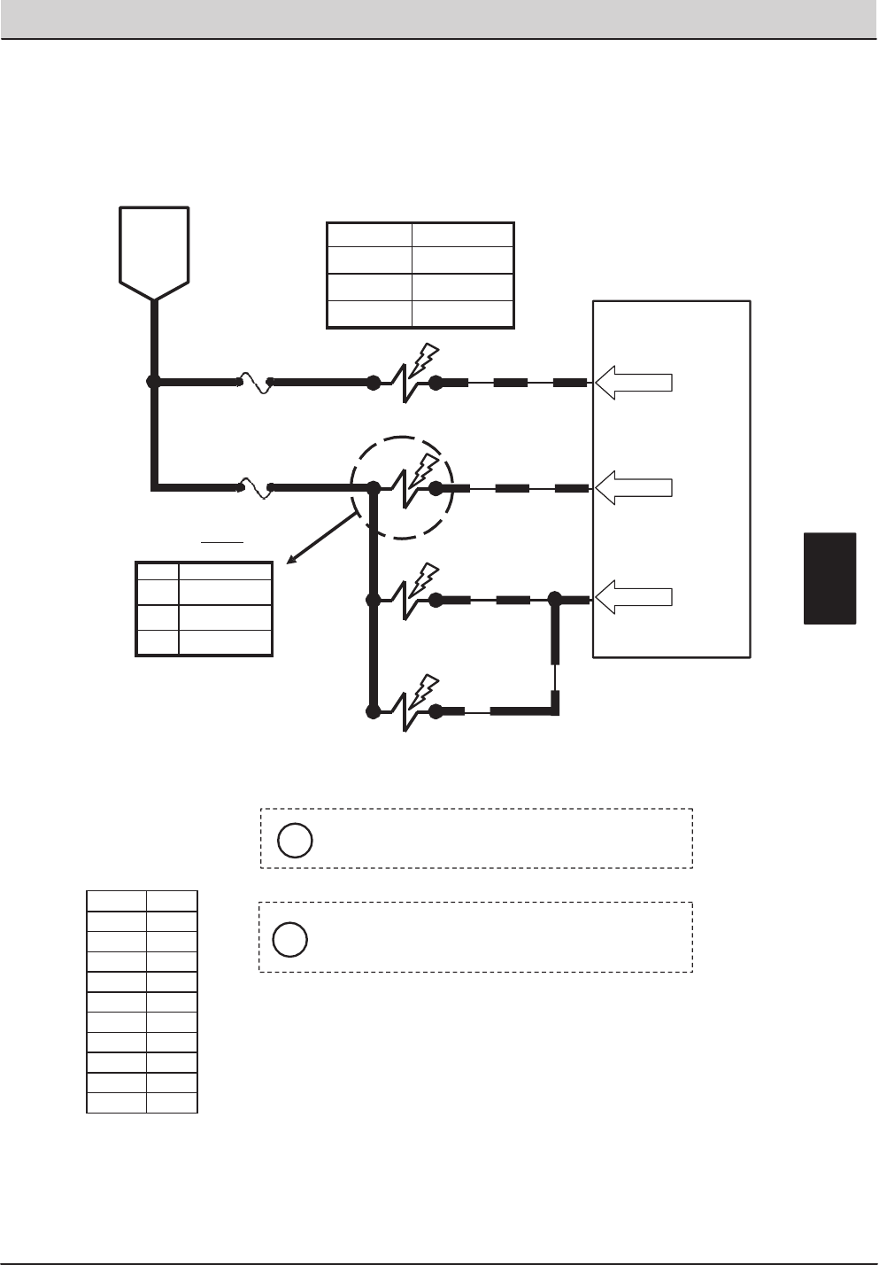
T20 Service Information (5-2017) 91
ELECTRICAL TROUBLESHOOTING
6 14
FUSE 5
15 AMP
14
14
MAIN BRUSHES
57
58
SV-2
SV-3
MAIN BRUSHES
LOWER
ROTATE 58
PIN P2-4
Touch Panel / Control Board
61
FUSE 6
PIN P2-8
15 AMP
SV-7
615 ENABLE VALVE
BRUSH HEAD
PRESSURE
PWM
BATTERY
POSITIVE
FROM
AUX 1
RELAY
CONTACTS
PIN P2-5
Wiring Color Codes
(Unless otherwise marked)
Typical Default
Amp Draw Readings (+/- 15%)
Maximum Amp. Draw Readings
Right Most Digit
of Wir e N umber
Color of Wire
0 Tan
1 Pink
2 Brown
3 Orange
4 Yellow
5 Green
6 Blue
7 Purple
8 Gray
9 White
Component Max Amp Draw
SV-3 1.7 A
SV-6 1.7 A
SV-7 1.7 A
Setting SV-2 Amp Draw
P1 285 mA
P2 395 mA
P3 490 mA
SV-6
iPressure settings P1, P2, & P3 are the Touch Panel
LED indicators for Brush down pressure.
i
SV-2 is controlled by PWM; a higher duty cycle
(more Brush Pressure LED’s lit on Touch
Panel) will result in more brush down pressure.
E
T20 Main Brushes ON
Conditions: Key on, engine running, scrubbing or sweeping system on, propel forward or reverse
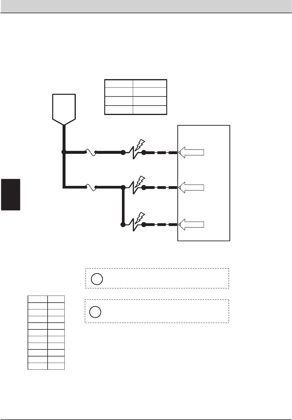
92 T20 Service Information (5-2017)
ELECTRICAL TROUBLESHOOTING
6 14
BATTERY
POSITIVE
FROM
AUX 1
RELAY
CONTACTS
Touch Panel / Control Board
61
FUSE 6
15 AMP
FUSE 5
15 AMP
6
14
15
56
59
SV-7
SV-1
SV-4
ENABLE
VALVE
SCRUB
VACUUM
FAN ON
SIDE & REAR
SQUEEGEES
LOWER
PIN P2-8
PIN P2-28
PIN P2-6
Maximum Amp Draw Readings
Right Most Digit
of Wir e N umber
Color of Wire
0 Tan
1 Pink
2 Brown
3 Orange
4 Yellow
5 Green
6 Blue
7 Purple
8 Gray
9 White
Component Max Amp Draw
SV-1 1.7 A
SV-4 1.7 A
SV-7 1.7 A
i
Any condition that cancels the scrub functions will
also turn OFF the scrub vacuum fan and raise
squeegees.
i
Reverse propel will turn OFF SV-4 (Pin P2-6) and
raise the side and rear squeegees.
T20 Scrub Vacuum Fan ON & Squeegees DOWN
Conditions: Key ON, Engine Running, Scrubbing System & Scrub Vacuum On, Propelling Forward
E

T20 Service Information (5-2017) 93
ELECTRICAL TROUBLESHOOTING
61
6FUSE 6
PIN P2-8
15 AMP
SV-7
15
15
15
15
64
62
SV-10
SV-8
SV-12
ENABLE VALVE
SIDE
BRUSH
PRESSURE
SIDE
BRUSH RUN
SIDE
BRUSH EXTEND
62
PWM
66
SIDE
BRUSH DOWN
SV-11
PIN P2-11
PIN P2-9
PIN P2-12
15
Wiring Color Codes
(Unless otherwise marked)
Typical Default
Amp Draw Readings (+/- 15%)
Maximum Amp Draw Readings
BATTERY
POSITIVE
FROM
AUX 1
RELAY
CONTACTS
Touch Panel / Control Board
Right Most Digit
of Wir e N umber
Color of Wire
0 Tan
1 Pink
2 Brown
3 Orange
4 Yellow
5 Green
6 Blue
7 Purple
8 Gray
9 White
Component Max Amp Draw
SV-7 1.7 A
SV-8 1.7 A
SV-11 1.7 A
SV-12 1.7 A
Setting SV-10 Amp Draw
P1 530 mA
P2 625 mA
P3 715 mA
i
SV-10 is controlled by PWM; a higher duty cycle
(more Brush Pressure LED’s lit on Touch Panel) will
result in more Brush Down pressure.
i
Pressure settings P1, P2, & P3 are the Touch
Panel LED indicators for Brush Down Pressure.
T20 Side Brush ON
Conditions: Key ON, Engine Running, Scrubbing System & Scrub Vacuum On, Propelling Forward or Back
E
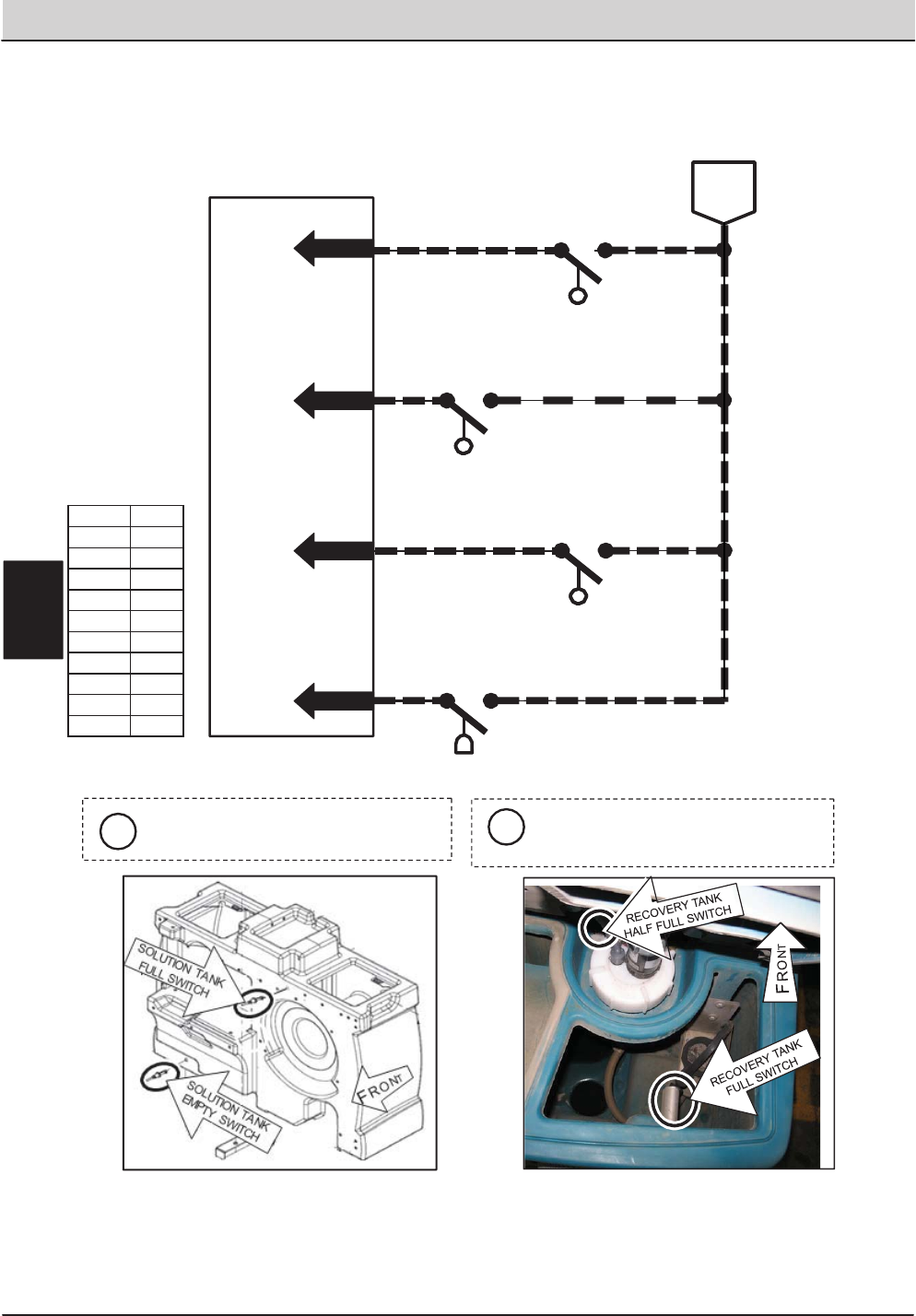
94 T20 Service Information (5-2017)
ELECTRICAL TROUBLESHOOTING
Wiring Color Codes
(Unless otherwise marked)
Right Most Digit
of Wir e N umber
Color of Wire
0 Tan
1 Pink
2 Brown
3 Orange
4 Yellow
5 Green
6 Blue
7 Purple
8 Gray
9 White
Touch Panel / Control Board
OPEN = EMPTY
CLOSED = NOT EMPTY
46
PIN P1-11 177 13/BLK
BATTERY
NEGATIVE
PIN P1-12
PIN P1-14
45
PIN P1-13
13/BLK
13/BLK
13/BLK
44
OPEN = LESS THAN HALF FULL
CLOSED = HALF FULL OR MORE
OPEN = NOT FULL
CLOSED = FULL
RECOVERY TANK
OPEN = NOT FULL
CLOSED = FULL
RECOVERY TANK
HALF FULL SWITCH
S-16
S-15
FULL SWITCH
S-14
SOLUTION TANK
FULL SWITCH
S-19
SOLUTION TANK
EMPTY SWITCH
The Tank Level Switches must be
closed for five (5) seconds before any
output is affected.
i
iS-14, SA-15, & S-19 are Float Switches.
S-16 is a Pressure Tube Switch.
T20 Tank Level Switches
Conditions: Key ON
E
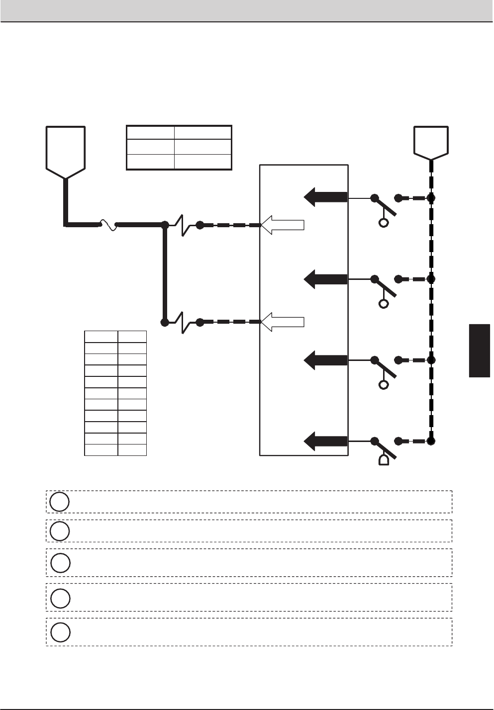
T20 Service Information (5-2017) 95
ELECTRICAL TROUBLESHOOTING
16
Touch Panel / Control Board
65
5FUSE 7
15 AMP
16
67
SOL-1
SOL-2
SOLUTION
TANK AUTO
FILL VALVE
CLOSED = NOT EMPTY
46
PIN P2-14
PIN P1-12
PIN P1-14
RECOVERY
TANK AUTO
FILL VALVE
45
PIN P1-13
13/BLK
13/BLK
13/BLK
44
OPEN = NOT FULL
CLOSED = FULL
OPEN = NOT FULL
CLOSED = FULL
OPEN = EMPTY
177 13/BLK
BATTERY
POSITIVE
FROM
AUX 2
RELAY
CONTACTS
BATTERY
NEGATIVE
PIN P2-13
PIN P1-11
RECOVERY TANK
HALF FULL SWITCH
S-16
S-15
RECOVERY TANK
FULL SWITCH
S-14
SOLUTION TANK
FULL SWITCH
S-19
SOLUTION TANK
EMPTY SWITCH
Wiring Color Codes
(Unless otherwise marked)
Maximum Amp Draw Readings
Right Most Digit
of Wir e N umber
Color of Wire
0 Tan
1 Pink
2 Brown
3 Orange
4 Yellow
5 Green
6 Blue
7 Purple
8 Gray
9 White
Component Max Amp Draw
SOL-1 1.7 A
SOL-2 1.7 A
OPEN = LESS THAN HALF FULL
CLOSED = HALF FULL OR MORE
iS-14, S-15, & S-19 are Float Switches.S-16 is a Pressure Tube Switch.
iSolution and Recovery Tank Auto Fill solenoids (SOL-1 & 2) are electro-mechanical devices.
iMachine must be in neutral and Solution Tank Full Switch OPEN (tank not full) to activate
Solution Tank Auto Fill Valve (SOL-1)..
iMachine must be in neutral and Recovery Tank Half Full Switch OPEN (tank less than half
full) to activate Recovery Tank Auto Fill Valve (SOL-2).
iThe Tank Level Switch must be closed for five (5) seconds before any output is affected..
T20 Auto Fill Solenoids (ES Equipped Machines Only)
Conditions: Key ON, Water Source Connected To Machine, Solution Tank NOT Full,
Recovery Tank Less Than Half Full
E
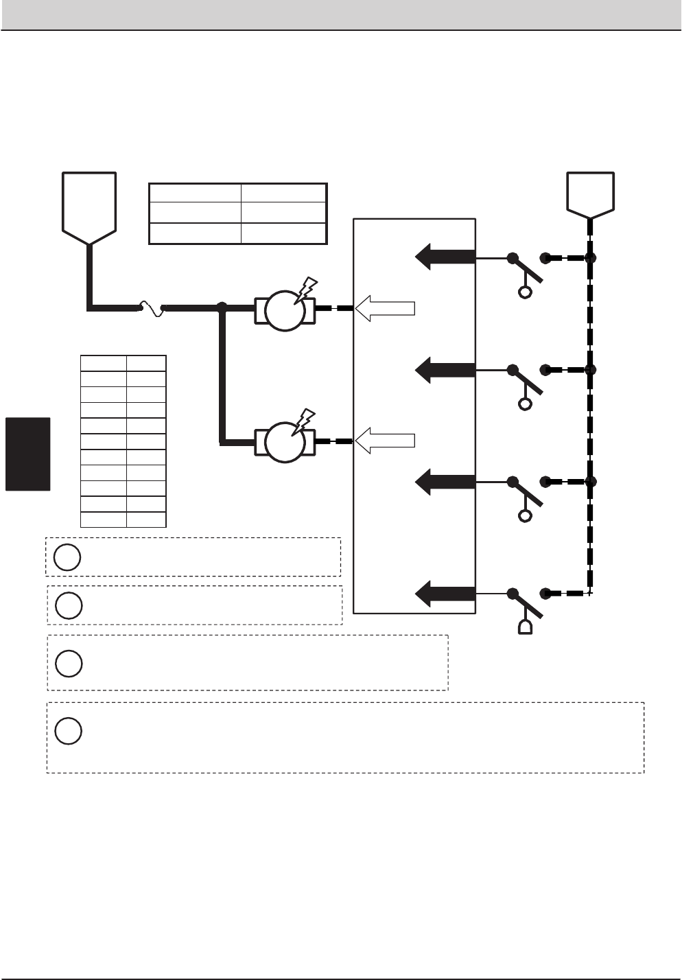
96 T20 Service Information (5-2017)
ELECTRICAL TROUBLESHOOTING
Touch Panel / Control Board
74
FUSE 8
15 AMP
517
75
DETERGENT
PUMP
BATTERY
POSITIVE
FROM
AUX 2
RELAY
CONTACTS
PIN P2-21
PIN P2-22
ES
PUMP
PWM
17
17 OPEN = EMPTY
CLOSED = NOT EMPTY
46
PIN P1-11 177 13/BLK
BATTERY
NEGATIVE
PIN P1-12
PIN P1-14
45
PIN P1-13
13/BLK
13/BLK
13/BLK
44
OPEN = NOT FULL
CLOSED = FULL
OPEN = LESS THAN HALF FULL
CLOSED = HALF FULL OR MORE
OPEN = NOT FULL
CLOSED = FULL
RECOVERY TANK
HALF FULL SWITCH
S-16
S-15
RECOVERY TANK
FULL SWITCH
S-14
SOLUTION TANK
FULL SWITCH
S-19
SOLUTION TANK
EMPTY SWITCH
Wiring Color Codes
(Unless otherwise marked)
Maximum Amp Draw Readings
Right Most Digit
of Wir e N umber
Color of Wire
0 Tan
1 Pink
2 Brown
3 Orange
4 Yellow
5 Green
6 Blue
7 Purple
8 Gray
9 White
Component Max Amp Draw
Detergent Pump 1.7 A
ES Pump n/a
iS-14, S-15, & S-19 are Float Switches, S-16
is a Pressure Tube Switch
iThe Tank Level Switches must be closed for
5 seconds before any output is affected.
i
The Detergent Pump is controlled by PWM; A higher duty cycle
(more Solution LED’s lit on Touch Panel) will result in more
detergent & solution applied to floor
i
The Recovery Tank must be at least half full for ES Pump to turn ON. This will begin a 30 second run
cycle of the ES Pump. If the Recovery Tank is still at least half full after the cycle, another 30 second
cycle will begin. If a full Solution Tank is sensed, the ES Pump will turn OFF before completing 30
second cycle.
T20 Conventional Detergent Pump & ES Pump
Conditions: Key ON, Engine Running, Scrubbing System ON, Recovery Tank Half Full
or More, Solution Tank Not Full, Two or Three Solution LED’s Lit.
E
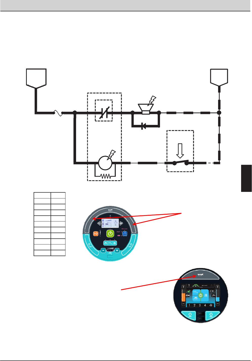
T20 Service Information (5-2017) 97
ELECTRICAL TROUBLESHOOTING
25 30
1/RED FUSE 3
15 AMP
HORN
RELAY
23 13/BLK
25
S-22
HORN
SWITCH
OPEN = HORN OFF
CLOSED = HORN ON
92 13/BLK
D1
23 13/BLK
Wiring Color Codes
(Unless otherwise marked)
M5A
UN-
SWITCHED
BATTERY
POSITIVE
BATTERY
NEGATIVE
M5B HORN
86 85
87
Right Most Digit
of Wir e N umber
Color of Wire
0 Tan
1 Pink
2 Brown
3 Orange
4 Yellow
5 Green
6 Blue
7 Purple
8 Gray
9 White
Horn Location
Membrane Panel
Horn Location
Pro Panel
T20 Horn
Conditions: Key on, switch activated
E
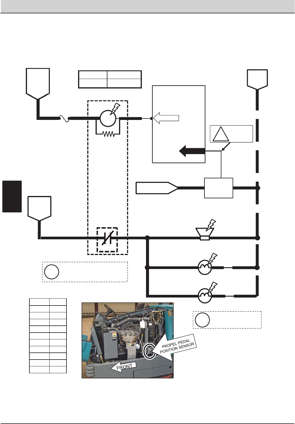
98 T20 Service Information (5-2017)
ELECTRICAL TROUBLESHOOTING
8
91
Touch Panel / Control Board
BATTERY
POSITIVE
FROM
FUSE 1
M4B
20 13/BLK
BATTERY POSITIVE
FROM FUSE 5
PROPEL
PEDAL
POSITION
SENSOR
14 WHT
DIGITAL
2GROUND3
SENSOR OUTPUT VOLTAGES:
2.0 to 2.7 VDC = NEUTRAL
2.8 VDC OR HIGHER = REVERSE
1.9 VDC OR LOWER = FORWARD
REVERSE ALARM/
WARNING LIGHT
20
13/BLK
13/BLK
REVERSE
TAIL LIGHT
20 (RIGHT)
20
REVERSE
TAIL LIGHT
(LEFT)
Wiring Color Codes
(Unless otherwise marked)
13/BLK
BATTERY
NEGATIVE
16
5FUSE 7
15 AMP
Maximum Amp Draw Readings
BATTERY
POSITIVE
FROM
AUX 2
RELAY
CONTACTS
70
REVERSE
RELAY
PIN P2-17
PIN P1-1
131/BLK-
1SENSOR
OUTPUT
2.8 VDC OR
iHIGHER IN
REVERSE
M4A
86 85
30 87
See Forward Propel page for
information on adjusting
Propel Pedal Position Sensor
Reverse propel will turn OFF
SV-4 (Pin P2-6) and raise the
side and rear squeegees.
i
i
Right Most Digit
of Wir e N umber
Color of Wire
0 Tan
1 Pink
2 Brown
3 Orange
4 Yellow
5 Green
6 Blue
7 Purple
8 Gray
9 White
Component Max Amp Draw
M4A 200 mA
T20 Reverse Propel
Conditions: Key ON, Propel Pedal Pushed For Reverse Travel
E
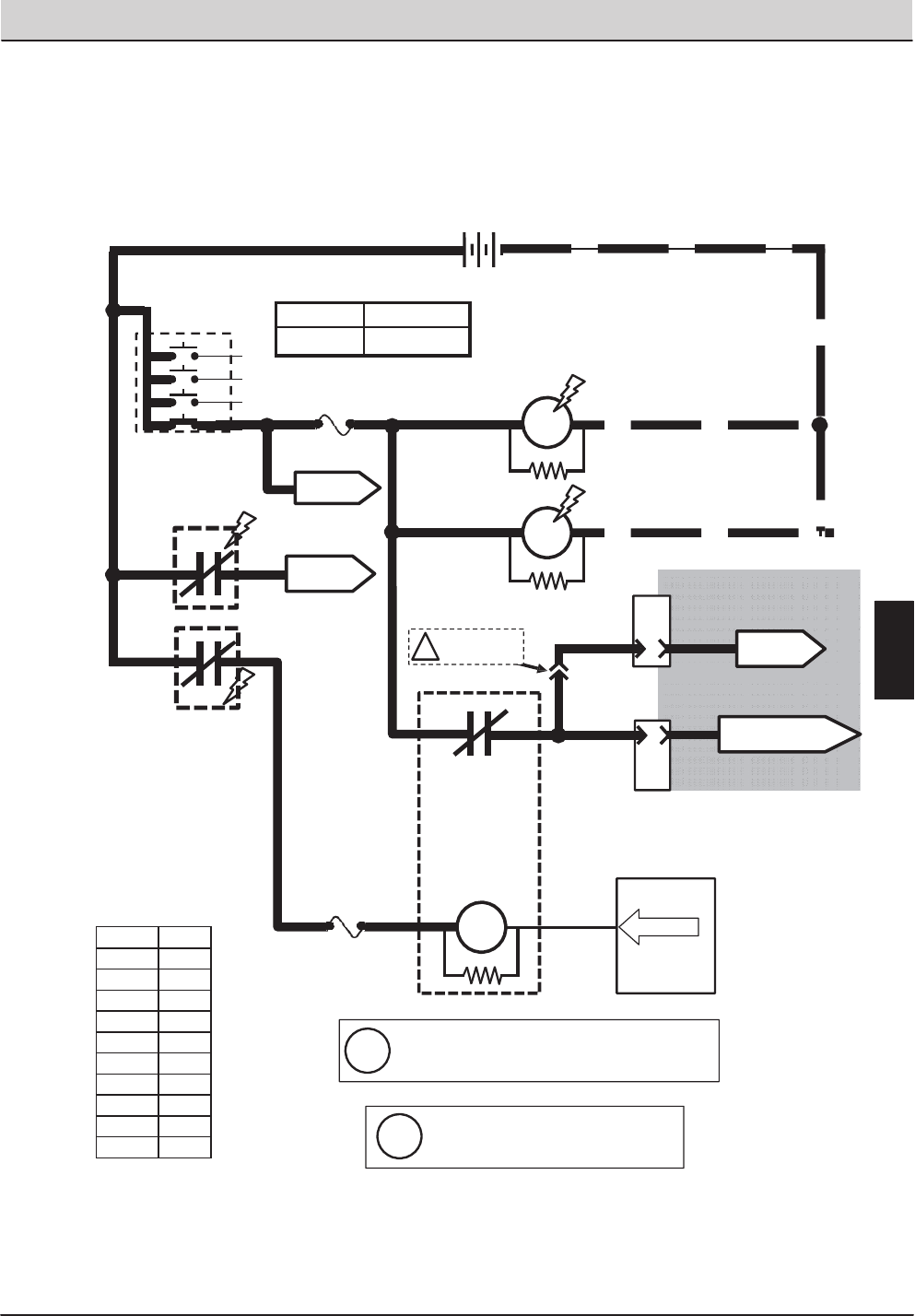
T20 Service Information (5-2017) 99
ELECTRICAL TROUBLESHOOTING
M6C
OPEN = MACHINE
SHUTDOWN
CLOSED = NORMAL
OPERATION
Touch Panel /
Control Board
165 FUSE 7
15 AMP
71
SHUTDOWN
RELAY
PIN P2-18
M6A
1/RED
1/RED
6
5
M1B
M2B
AUX. 1 RELAY
CONTACTS
AUX. 2 RELAY
CONTACTS
AUXILIARY
RELAY
87a 38 30
8 13/BLK
13/BLK
Wiring Color Codes
(Unless otherwise marked)
AUXILIARY
RELAY
A
10
D
PIN
8
PIN
CONNECT FOR
L.P.G. ONLY
!
1/RED 13/BLK
+-
12 VDC
1/RED
3 PINK
76
TO FUSES
5 &6
TO ENGINE
ECM
8
8
FUSE 1
15 AMP
M1A
M2A
KEY SWITCH
RUN
86 85
4
TO FUSES
9 & 12
4
4
J-12
ENGINE HARNESS
CONNECTORS
J-11
TAN/BRN
TO FUSE 1 OF
ENGINE HARNESS
Refer to the Engine
Controller schematics
The Shutdown system is used to turn OFF the
iengine under certain conditions on machines
with certain optional equipment
When control board turns ON M6A,
ithe engine ECM loses power, and
the engine shuts OFF
Maximum Amp Draw Readings
Right Most Digit
of Wir e N umber
Color of Wire
0 Tan
1 Pink
2 Brown
3 Orange
4 Yellow
5 Green
6 Blue
7 Purple
8 Gray
9 White
Component Max Amp Draw
M6A 200 mA
T20 Shutdown Relay (Normal Machine Operation)
(GAS / LPG)
E
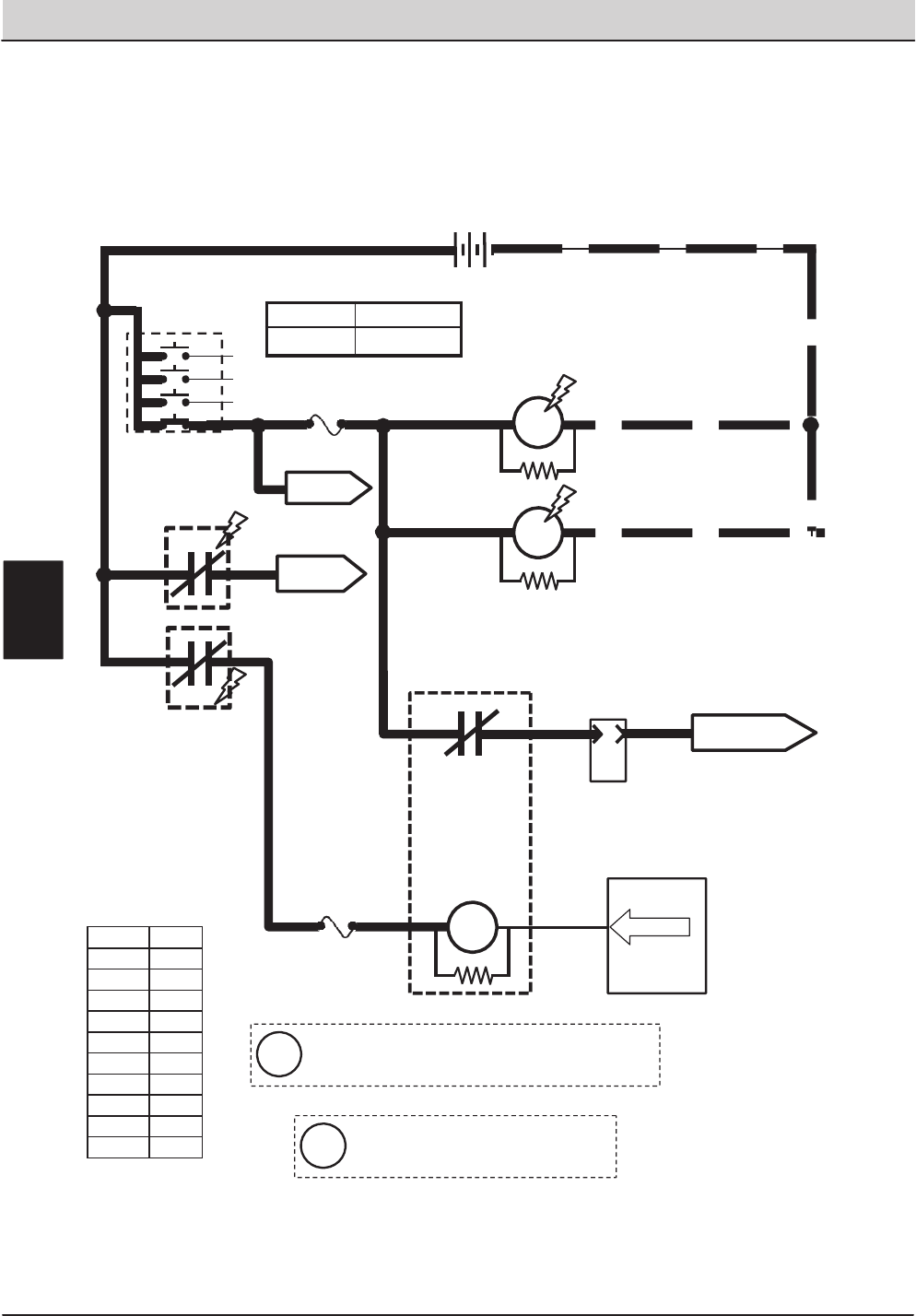
100 T20 Service Information (5-2017)
ELECTRICAL TROUBLESHOOTING
M6C
OPEN = MACHINE
SHUTDOWN
CLOSED = NORMAL
OPERATION
Touch Panel /
Control Board
165 FUSE 7
15 AMP
71
SHUTDOWN
RELAY
PIN P2-18
M6A
1/RED 13/BLK
+-
12 VDC
1/RED
1/RED
1/RED
6
5
M1B
M2B
AUX. 1 RELAY
CONTACTS
AUX. 2 RELAY
CONTACTS
AUXILIARY
RELAY
3
830
8 13/BLK
13/BLK
Wiring Color Codes
(Unless otherwise marked)
AUXILIARY
RELAY
A
10
PIN
TO FUSES
5 &6
TO FUEL PUMP
RELAY M10
8
8
FUSE 1
15 AMP
M1A
M2A
KEY SWITCH
RUN
86 85
87a
4
TO FUSES
9 & 12
4
4
3
J-11
ENGINE HARNESS
CONNECTOR
Maximum Amp Draw Readings
When control board turns ON M6A,
the engine ECM loses power, and
engine shuts OFF
i
Right Most Digit
of Wir e N umber
Color of Wire
0 Tan
1 Pink
2 Brown
3 Orange
4 Yellow
5 Green
6 Blue
7 Purple
8 Gray
9 White
Component Max Amp Draw
M6A 200 mA
T20 Shutdown Relay (Normal Machine Operation)
(Diesel)
The Shutdown system is used to turn OFF the
engine under certain conditions on machines
with certain optional equipment
i
E
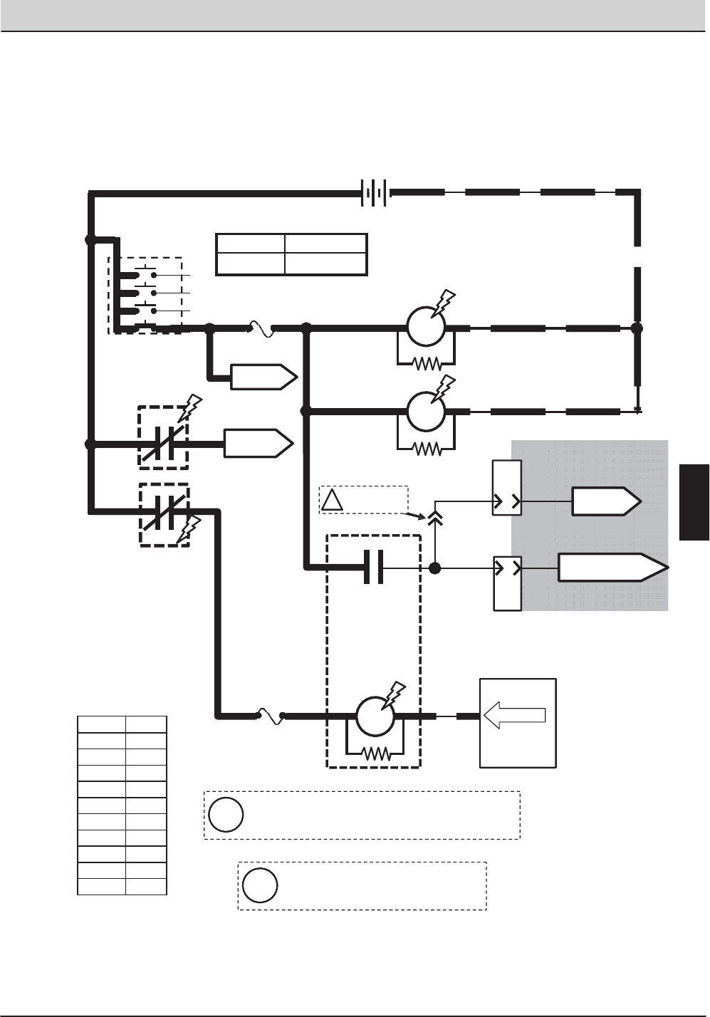
T20 Service Information (5-2017) 101
ELECTRICAL TROUBLESHOOTING
A
10
PIN
1/RED 13/BLK
+
1/RED
FUSE 1
15 AMP
4
1/RED
1/RED
6
5
M1B
M2B
AUX. 2 RELAY
CONTACTS
AUXILIARY
RELAY
8
8
13/BLK
13/BLK
Touch Panel /
Control Board
16
5FUSE 7
15 AMP
Wiring Color Codes
(Unless otherwise marked)
AUXILIARY
RELAY
CONNECT FOR
L.P.G. ONLY
!
8
8
-
12 VDC
3 PINK
76
TO FUSES
5 &6
PIN P2-18
M1A
M2A
KEY SWITCH
RUN
71
SHUTDOWN
RELAY
M6A
87a 38 30
M6C
OPEN = MACHINE
SHUTDOWN
CLOSED = NORMAL
OPERATION
86 85
TO FUSES
9 & 12
4
4
D
8
PIN
J-12
ENGINE HARNESS
CONNECTORS
J-11
TO ENGINE
ECM
TAN/BRN
TO FUSE 1 OF
ENGINE HARNESS
Refer to the Engine
Controller schematics
Maximum Amp Draw Readings
AUX. 1 RELAY
CONTACTS
Right Most Digit
of Wir e N umber
Color of Wire
0 Tan
1 Pink
2 Brown
3 Orange
4 Yellow
5 Green
6 Blue
7 Purple
8 Gray
9 White
Component Max Amp Draw
M6A 200 mA
T20 Shutdown Relay (Shutdown Mode)
(GAS / LPG)
When control board turns ON M6A,
the engine ECM loses power, and
engine shuts OFF
i
The Shutdown system is used to turn OFF the
engine under certain conditions on machines
with certain optional equipment
i
E
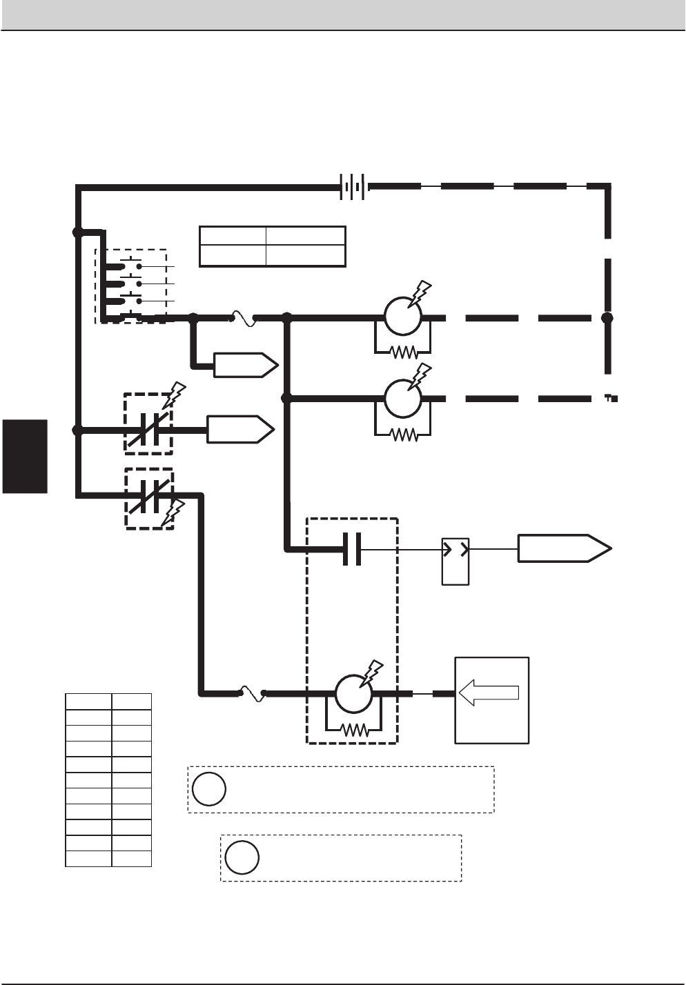
102 T20 Service Information (5-2017)
ELECTRICAL TROUBLESHOOTING
A
10
PIN
1/RED 13/BLK
+-
12 VDC
1/RED
FUSE 1
15 AMP
4
1/RED
1/RED
6
5
M1B
M2B
AUX. 2 RELAY
CONTACTS
AUXILIARY
RELAY
8
8
13/BLK
13/BLK
Touch Panel /
Control Board
16
5FUSE 7
15 AMP
Wiring Color Codes
(Unless otherwise marked)
AUXILIARY
RELAY
8
8
TO FUSES
5 &6
PIN P2-18
71
SHUTDOWN
RELAY
M6A
830
M6C
OPEN = MACHINE
SHUTDOWN
CLOSED = NORMAL
OPERATION
86 85
87a 3
M1A
M2A
KEY SWITCH
RUN
TO FUSES
9 & 12
4
4
TO FUEL PUMP
RELAY M10
J-11
ENGINE HARNESS
CONNECTOR
3
Maximum Amp Draw Readings
AUX. 1 RELAY
CONTACTS
Right Most Digit
of Wir e N umber
Color of Wire
0 Tan
1 Pink
2 Brown
3 Orange
4 Yellow
5 Green
6 Blue
7 Purple
8 Gray
9 White
Component Max Amp Draw
M6A 200 mA
T20 Shutdown Relay (Shutdown Mode)
(Diesel)
When control board turns ON M6A,
the engine ECM loses power, and
engine shuts OFF
i
The Shutdown system is used to turn OFF the
engine under certain conditions on machines
with certain optional equipment
i
E
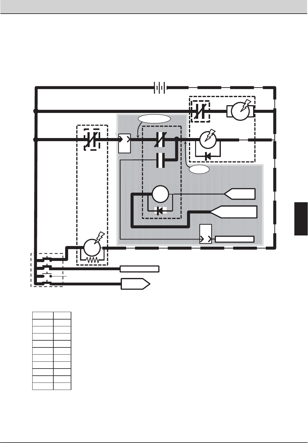
T20 Service Information (5-2017) 103
ELECTRICAL TROUBLESHOOTING
10
PIN
K
1/RED 13/BLK
+
1/RED
4
STARTER
RELAY
85
77
TO FUSES
1, 9, & 12
2
KEY SWITCH
START
Wiring Color Codes
(Unless otherwise marked)
M7A
STARTER MOTOR
ASSEMBLY
J
10
PIN
ENGINE
HARNESS
CONNECTOR
J-11
J-11
FROM ECM
PIN 9
FROM FUSE 1 OF
ENGINE HARNESS
STARTER
LOCKOUT
RELAY
1/RED
ENGINE
BLOCK
13/BLK
M7B
86
30
87a
87
ENGINE
BLOCK
86 85
30 87
ENGINE HARNESS
CONNECTOR
NO CONNECTION
GRAY/ORANGE
PINK/BLK
PINK/BLK
LT.BLUE/PINK
PINK/TAN
-
12 VDC
NO CONNECTION
Refer to the Engine
Controller schematics
WHITE
Right Most Digit
of Wir e N umber
Color of Wire
0 Tan
1 Pink
2 Brown
3 Orange
4 Yellow
5 Green
6 Blue
7 Purple
8 Gray
9 White
T20 Starting System ON
Conditions: Key Turned To Start Position
(Gas – LPG)
E
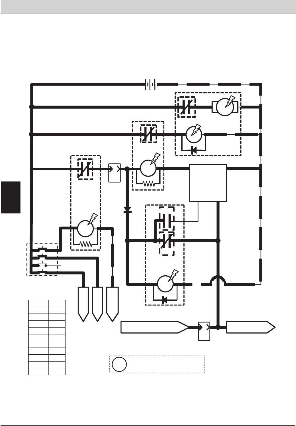
104 T20 Service Information (5-2017)
ELECTRICAL TROUBLESHOOTING
4
STARTER
RELAY
87 77 77
2
KEY SWITCH
START
Wiring Color Codes
(Unless otherwise marked)
M7A
J
10
PIN
ENGINE
HARNESS
CONNECTOR
J-11
TO BATTERY
NEGATIVE
85 13/BLK
M7B
30
3
M8B
STARTER
RELAY
M8A
85 13/BLK
M9A
STARTER
LOCKOUT
RELAY
86
30 87
TO FUSES
1, 9, & 12
TO
GLOWPLUGS
42
1/RED
1/RED
13/BLK
13/BLK
SWITCHED BATTERY POSITIVE
FROM SHUTDOWN RELAY M6C
STARTER
TIMER
MODULE
A
10
PIN
33
3
87a
56 3
77
82
55
55
D-3
PIN 1
GND
PIN 2
LOAD
PIN 6 PIN 3
INIT B+
56
86
30 83
85
86
87
TO FUEL PUMP RELAY
M10 & GOVERNOR
J-11
ENGINE HARNESS
CONNECTOR
M9B
M9C
1/RED 13/BLK
+-
12 VDC
1/RED
STARTER MOTOR
ASSEMBLY
1/RED
ENGINE
BLOCK
ENGINE
BLOCK
The Starter Timer Module creates
a delay between start attempts
i
Right Most Digit
of Wir e N umber
Color of Wire
0 Tan
1 Pink
2 Brown
3 Orange
4 Yellow
5 Green
6 Blue
7 Purple
8 Gray
9 White
T20 Starting System ON
Conditions: Key Turned To Start Position
(Diesel)
E
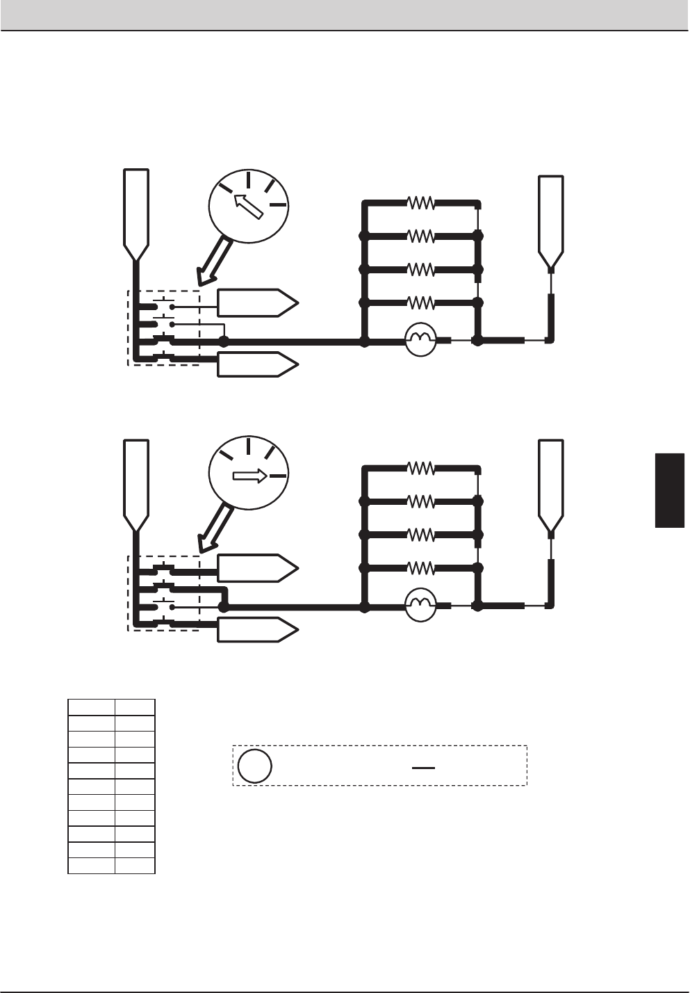
T20 Service Information (5-2017) 105
ELECTRICAL TROUBLESHOOTING
Glow
Plug
START
RUN
OFF
KEY SWITCH
KEY SWITCH
START
Wiring Color Codes
(Unless otherwise marked)
KEY SWITCH
GLOW PLUG
42
1/RED
FROM BATTERY
POSITIVE
TO FUSES
1, 9, & 12
TO START
RELAY M7A
GP4
GP3
GP2
CH ASS IS GRO UNDS
FROM BATTERY
NEGATIVE
GLOW PLUG LAMP
13/BLK
FROM BATTERY
POSITIVE
TO FUSES
1, 9, & 12
TO START
RELAY M7A
GLOW PLUGS
GP4
GP3
GP2
GP1
CH ASS IS GRO UNDS
FROM BATTERY
NEGATIVE
GLOW PLUG LAMP
13/BLK
42
42
42
42
42
42
1/RED
42
42
42
42
42
42
GLOW PLUGS
GP1
42
The Glow Plugs are ON only when ignition
switch is in the “Glow Plug” or “Start” position
Glow
Plug START
RUN
OFF
KEY SWITCH
i
Right Most Digit
of Wir e N umber
Color of Wire
0 Tan
1 Pink
2 Brown
3 Orange
4 Yellow
5 Green
6 Blue
7 Purple
8 Gray
9 White
T20 Glow Plugs ON
Conditions: Key Turned To Start Position / Glow Plug
(Diesel)
E
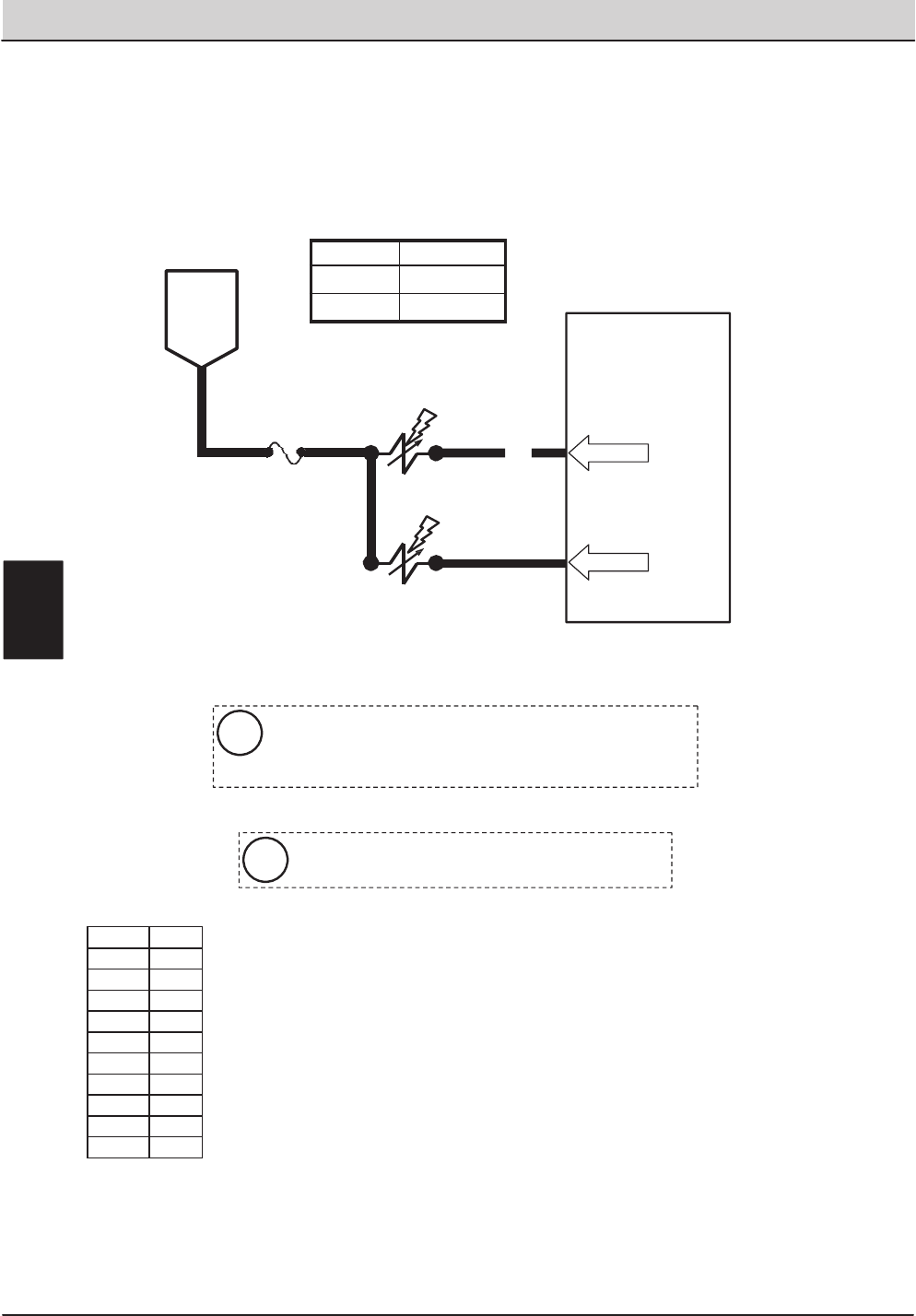
106 T20 Service Information (5-2017)
ELECTRICAL TROUBLESHOOTING
Touch Panel / Control Board
72
FUSE 7
PIN P2-19
15 AMP
SOL-3
16
516
181
SOL-7
MAIN BRUSH
SOLUTION VALVE
BATTERY
POSITIVE
FROM
AUX 2
RELAY
CONTACTS
PIN P2-20
SIDE BRUSH
SOLUTION VALVE
Wiring Color Codes
(Unless otherwise marked)
Maximum Amp Draw Readings
The Solution Valves will function only while propelling
forward or reverse during scrub operation
i
E
Right Most Digit
of Wir e N umber
Color of Wire
0 Tan
1 Pink
2 Brown
3 Orange
4 Yellow
5 Green
6 Blue
7 Purple
8 Gray
9 White
Component Max Amp Draw
SOL-3 1.7 A
SOL-7 1.7 A
T20 Conventional Main & Side Brush Solution Valves
Conditions: Key On, Scrubbing System On, Side Brush On, Forward or Reverse Propel,
One or More Solution LED’s Lit.
The Solution Valves are pulsed slowly to adjust the solution
volume. Less OFF time (more Solution LED’s lit on
Control Pad will result in more solution applied to floor
i
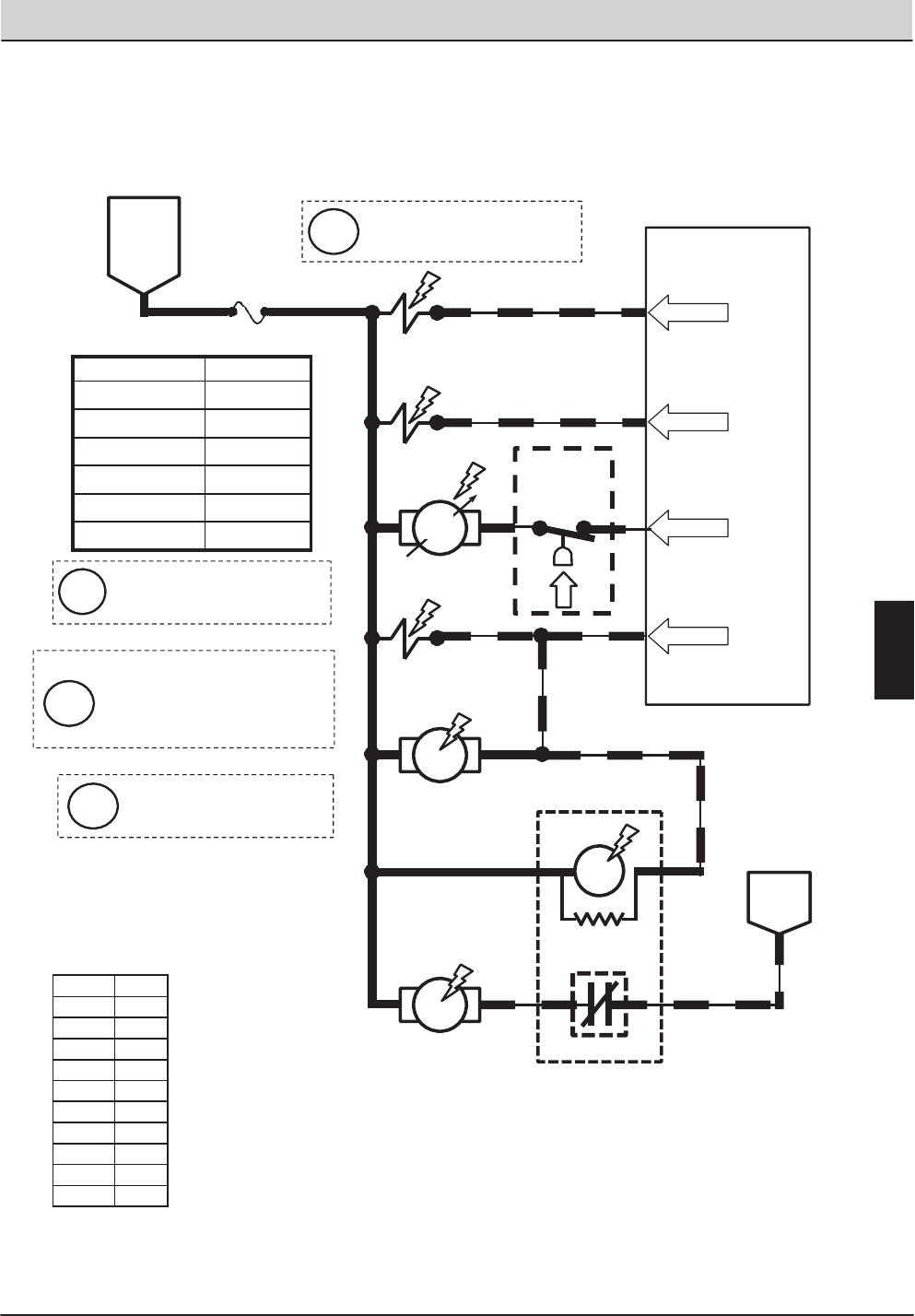
T20 Service Information (5-2017) 107
ELECTRICAL TROUBLESHOOTING
PIN P2-23
15 AMP
SOL-5
17
Wiring Color Codes
(Unless otherwise marked)
79
FUSE 8
5
17 FaST DETERGENT
PUMP
17
FaST AIR
PUMP
17
80
75
SOL-6
SOL-4
FaST SIDE
BRUSH VALVE
FaST
ENABLE
VALVE
75
74
PIN P2-26
PIN P2-22
PIN P2-21
17
FaST
WATER
PRESSURE
SWITCH
83
BATTERY
NEGATIVE
M11A
FaST WATER
PUMP RELAY
30 87
M11B
75
75
75
75
17
17
FaST WATER
PUMP
17
86 13/BLK
86 85
Touch Panel / Control Board
FaST HIGH
FLOW VALVE
BATTERY
POSITIVE
FROM
AUX 2
RELAY
CONTACTS
PWM
Right Most Digit
of Wir e N umber
Color of Wire
0 Tan
1 Pink
2 Brown
3 Orange
4 Yellow
5 Green
6 Blue
7 Purple
8 Gray
9 White
Component Max Amp Draw
SOL-4 1.7 A
SOL-5 1.7 A
SOL-6 1.7 A
M11A 200 mA
FaST Det. Pump 1.7 A
FaST Air Pump 1.7 A
T20 FaST System ON
Conditions: Key On, Scrubbing System On, Side Brush On, Forward or Reverse Propel, Three Solution LED’s Lit
FaST High Flow Valve is ON
only when all three Solution
LED’s are lit
i
One or Two Solution LED’s lit
selects LOW FaST output
i
FaST Water Pressure Switch:
OPEN = Less than 10 PSI
Closed = More Than 10 PSI
i
The FaST Detergent Pump is
controlled a by PWM: A higher
duty cycle (more Solution LED’s
lit on Control Pod), will result in
more FaST foam applied
i
E
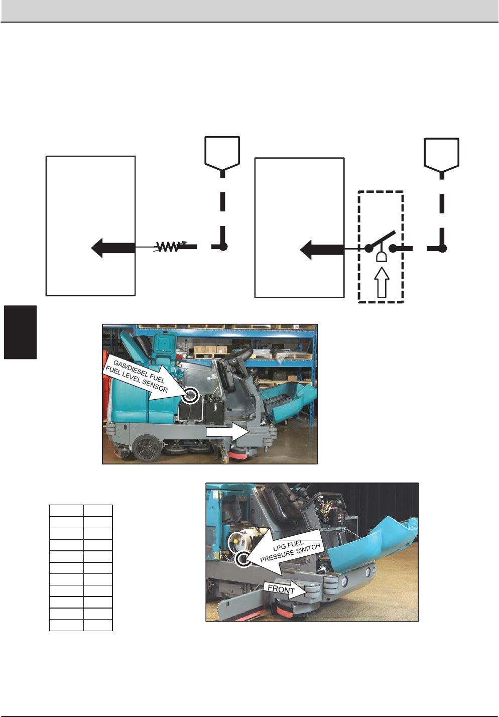
108 T20 Service Information (5-2017)
ELECTRICAL TROUBLESHOOTING
Wiring Color Codes
(Unless otherwise marked)
30
Touch Panel / Control Board
GAS /
DIESEL 13/BLK
BATTERY
NEGATIVE
100 OHMS = FULL TANK
5 OHMS = EMPTY TANK
S-7
FUEL LEVEL
SENDER
PIN P1-4 DIGITAL
GROUND
30
Touch Panel / Control Board
LPG
13/BLK
BATTERY
NEGATIVE
NORMALLY CLOSED, HELD
OPEN BY FUEL PRESSURE
OPEN = MORE THAN 70 PSI
CLOSED = 70 PSI OR LOWER
S-8
FUEL
PRESSURE
SWITCH
S-8
PIN P1-4 DIGITAL
GROUND
131/BLK-
WHT
131/BLK-
WHT
FRONT
Right Most Digit
of Wir e N umber
Color of Wire
0 Tan
1 Pink
2 Brown
3 Orange
4 Yellow
5 Green
6 Blue
7 Purple
8 Gray
9 White
T20 Fuel Level Sensors
Conditions: Key On
E
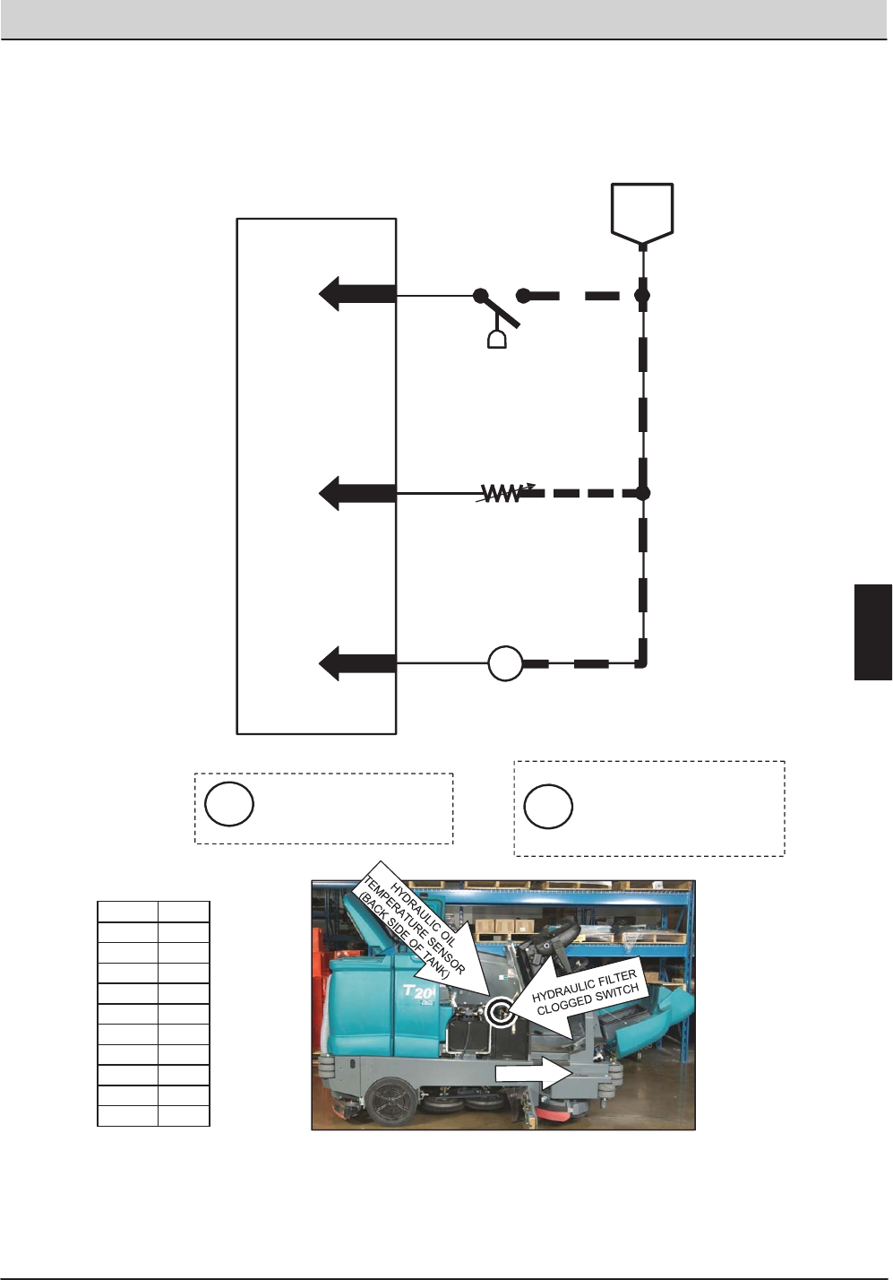
T20 Service Information (5-2017) 109
ELECTRICAL TROUBLESHOOTING
Wiring Color Codes
(Unless otherwise marked)
BATTERY
NEGATIVE
Touch Panel / Control Board
HYDRAULIC FILTER
CLOGGED SWITCH
S-17
OPEN = LESS THAN 20 PSI (FILTER OK)
CLOSED = MORE THAN 20 PSI (FILTER
CLOGGED)
49
90 13/BLK
PIN P1-15
PIN P1-21
78
PIN P1-17
13/BLK
S-23
OPEN = NO IMPACT DETECTED
CLOSED = IMPACT DETECTED
S-20
HYDRAULIC OIL
TEMPERATURE SENSOR
131/BLK-WHT
DIGITAL
GROUND
IMPACT
SENSOR
0.8 VDC OR LESS = 220°F OR HIGHER
ABOVE 0.8 VDC = UNDER 220°F
FRONT
Right Most Digit
of Wir e N umber
Color of Wire
0 Tan
1 Pink
2 Brown
3 Orange
4 Yellow
5 Green
6 Blue
7 Purple
8 Gray
9 White
T20 Impact, Hydraulic Temp & Filter Sensor
Conditions: Key On
The hydraulic Filter Clogged
switch will not be sensed
until after the machine has
run for five minutes to allow
the hydraulic oil to warm up
i
Impact Sensor S-23 is used
only on machines with
certain optional equipment
i
E
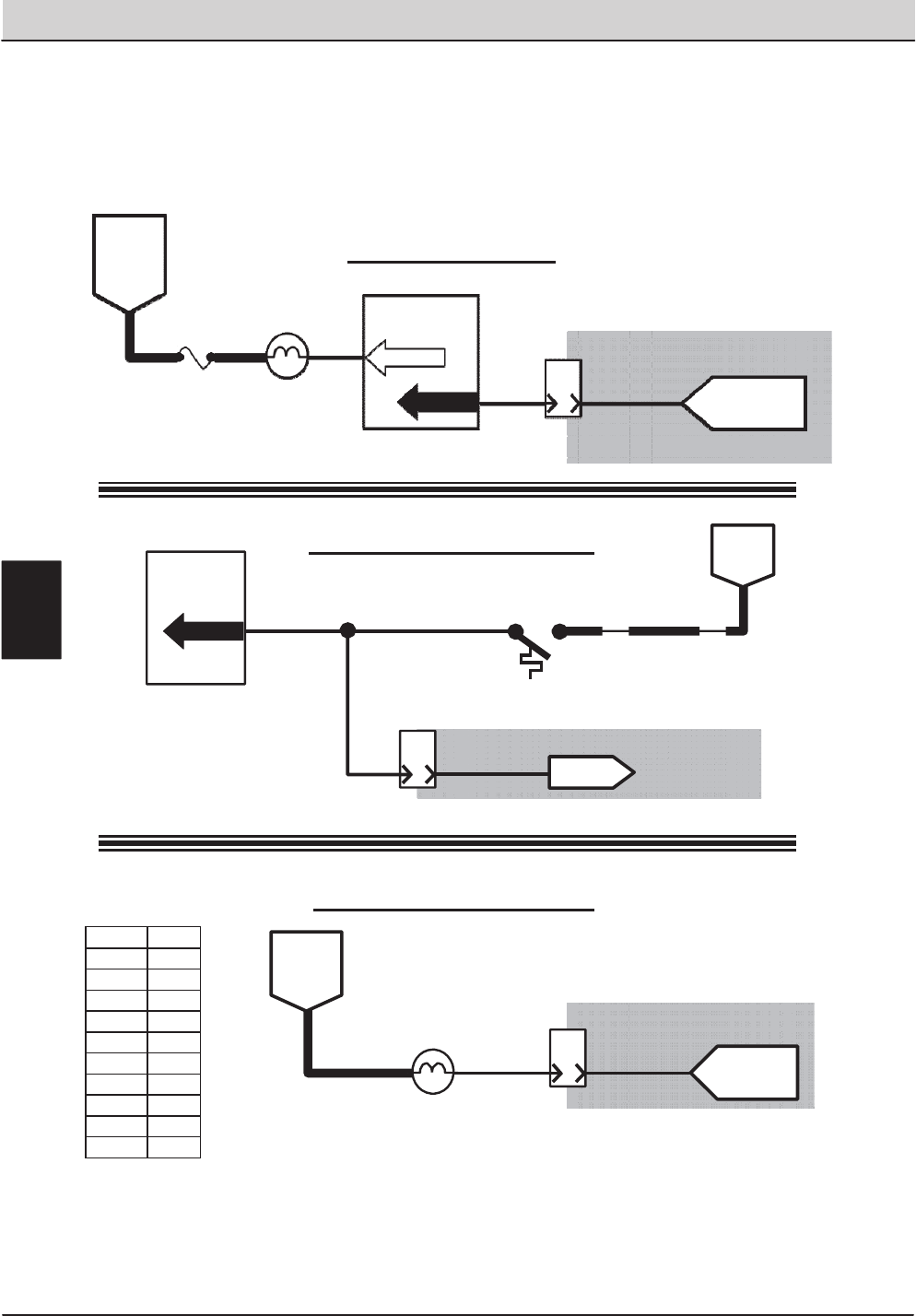
110 T20 Service Information (5-2017)
ELECTRICAL TROUBLESHOOTING
Wiring Color Codes
(Unless otherwise marked)
12
Touch Panel /
Control Board
PIN P1-18
SW2
OPEN = BELOW 220°F
CLOSED = ABOVE 220°F
B
8
PIN
TO ECM
PIN 35
BATTERY
NEGATIVE
HIGH ENGINE
TEMPERATURE
SWITCH 13/BLK
12
12
J-12
ENGINE HARNESS
CONNECTOR
F
10
PIN
10
SWITCHED
BATTERY
POSITIVE
FROM
FUSE 1
8MIL SIGNAL
FROM ECM
PIN 26
MIL (CHECK
ENGINE LAMP)
J-11
ENGINE HARNESS
CONNECTOR
6FUSE 5
15 AMP
FROM
AUX 1
RELAY
CONTACTS
Touch Panel /
Control Board
PIN P2-27
14 28
LOW ENGINE OIL
PRESSURE LAMP
J-12
8
PIN
A
9
PIN P1-19
OIL PRESSURE
SIGNAL FROM
ECM PIN 30
ENGINE HARNESS
CONNECTOR OPEN = LOW OIL PRESSURE
BATTERY NEG.= OIL PRESSURE OK
Engine Oil Pressure
Engine Temperature Switch
Malfunction Indicator Lamp
LT.BLUE/WHITE
TAN/DK.GREEN
LT.BLUE/BLK
Refer to the Engine
Controller schematics
Refer to the Engine
Controller schematics
Refer to the Engine
Controller schematics
Right Most Digit
of Wir e N umber
Color of Wire
0 Tan
1 Pink
2 Brown
3 Orange
4 Yellow
5 Green
6 Blue
7 Purple
8 Gray
9 White
T20 Engine Oil Pressure, Temperature, and MIL System
(Gas / LPG)
E
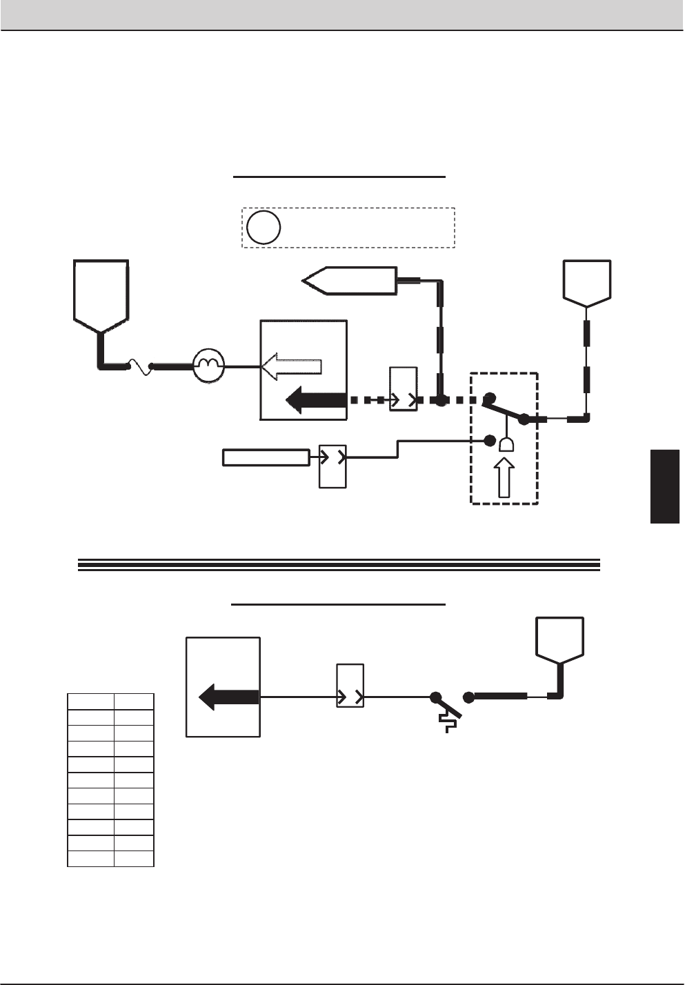
T20 Service Information (5-2017) 111
ELECTRICAL TROUBLESHOOTING
A
B
C
Wiring Color Codes
(Unless otherwise marked) 12
Touch Panel /
Control Board
PIN P1-18
ENGINE HARNESS
CONNECTOR
SW2
OPEN = BELOW 220°F
CLOSED = ABOVE 220°F
BATTERY
NEGATIVE
HIGH ENGINE
TEMPERATURE
SWITCH 13/BLK
Engine Temperature Switch
OIL PRESSURE
SWITCH
S-3
B&C CLOSED = LOW OIL PRESSURE
A&B CLOSED = OIL PRESSURE OK
6FUSE 5
15 AMP
BATTERY
POSITIVE
FROM
AUX 1
RELAY
CONTACTS
Touch Panel /
Control Board
PIN P2-27
14 28
LOW ENGINE OIL
PRESSURE LAMP
13/BLK
BATTERY
NEGATIVE
9
J-12
8
ENGINE HARNESS
CONNECTOR
TO FUEL PUMP
RELAY M10
E
10
PIN
ENGINE HARNESS
CONNECTOR
J-11
NO CONNECTION
55
5
27
27
B
8
PIN
J-12
12
PIN
A
PIN P1-19
This drawing is shown with key
switch ON, and engine running
i
Right Most Digit
of Wir e N umber
Color of Wire
0 Tan
1 Pink
2 Brown
3 Orange
4 Yellow
5 Green
6 Blue
7 Purple
8 Gray
9 White
T20 Engine Oil Pressure, Temperature, and MIL System
(Diesel)
Engine Oil Pressure Switch
E
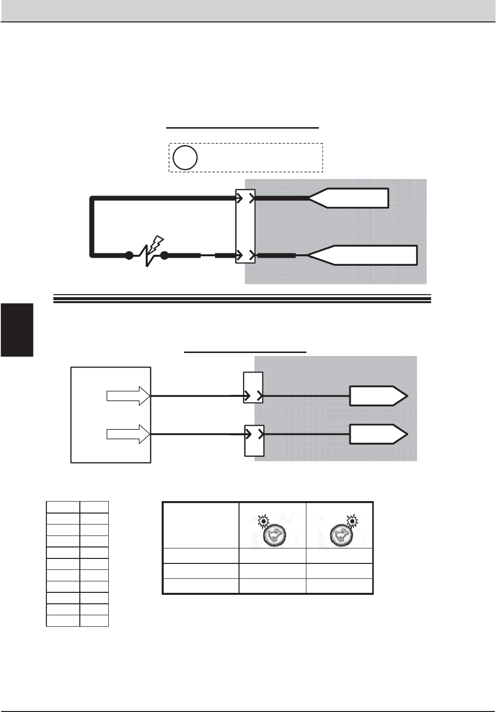
112 T20 Service Information (5-2017)
ELECTRICAL TROUBLESHOOTING
Wiring Color Codes
(Unless otherwise marked)
D
6
PIN
ENGINE HARNESS
CONNECTOR
J-10
BLACK
E
FROM FUSE 4 OF
ENGINE HARNESS
19
13/BLK
PINK/YEL
19
FUEL PUMP
Touch Panel / Control Board
11
18 Governor Speed “B”
PIN P2-24
PIN P2-25 B
6
PIN
J-10
8
PIN
E
J-12
ENGINE HARNESS
CONNECTORS
TO PIN 34
OF ECM
TO PIN 48
OF ECM
GRAY/DK.BLUE
YEL/DK.BLUE
Speed Control Output
Governor Speed “A”
FROM CHASSIS GROUND
OF ENGINE HARNESS
Refer to the Engine
Controller schematics
Refer to the Engine
Controller schematics
This drawing is shown with key
switch ON, and engine running
i
E
Right Most Digit
of Wir e N umber
Color of Wire
0 Tan
1 Pink
2 Brown
3 Orange
4 Yellow
5 Green
6 Blue
7 Purple
8 Gray
9 White
ENGINE
SPEED
CHART
Low Engine Speed High Engine Speed
Engine RPM 950 (+/- 25) 2400 (+/- 25)
Voltage Speed “A” 5 VDC 0 VDC
Voltage Speed “B” 0 VDC 0 VDC
T20 Fuel Pump & Engine Speed Control
(Gas / LPG)
Fuel Pump (Gasoline Only)
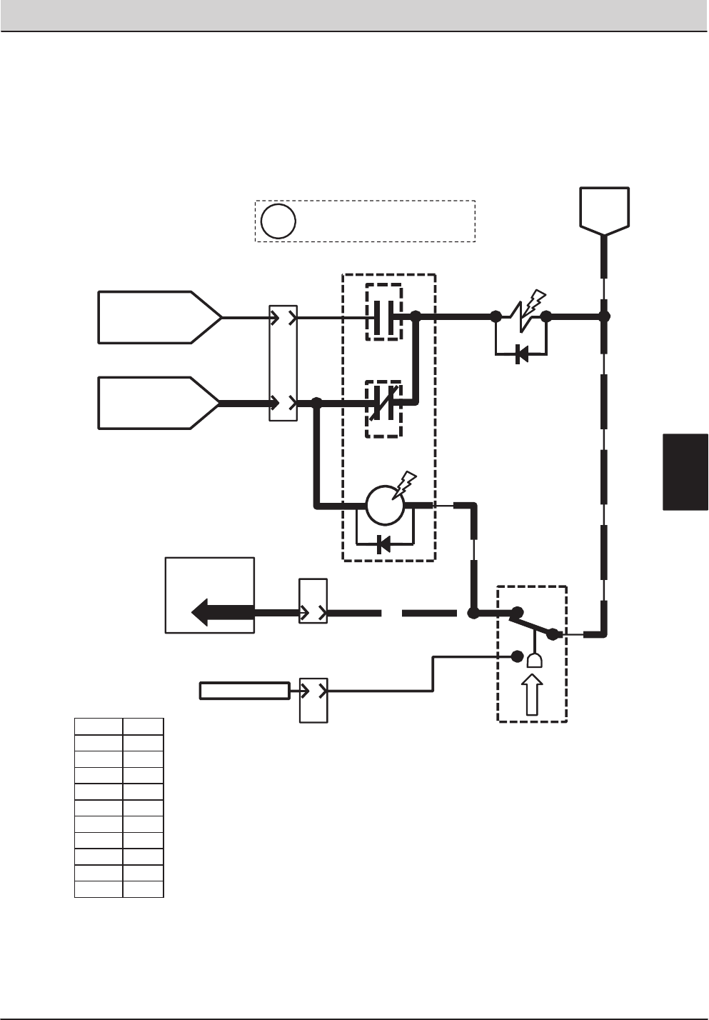
T20 Service Information (5-2017) 113
ELECTRICAL TROUBLESHOOTING
Wiring Color Codes
(Unless otherwise marked)
J
START RELAY M7B
10
PIN
ENGINE HARNESS
CONNECTOR
J-11
A
D-5
3
FUEL PUMP
85
M10A
FUEL
PUMP
RELAY
86
30
387
87a
M10B
M10C
OIL PRESSURE
SWITCH
S-3
B&C CLOSED = LOW OIL PRESSURE
A&B CLOSED = OIL PRESSURE OK
B13/BLK
A
C
55
27
BATTERY
POSITIVE WHILE
CRANKING FROM
13/BLK
BATTERY
NEGATIVE
SWITCHED
BATTERY POSITIVE
FROM SHUTDOWN
RELAY M6C
Touch Panel /
Control Board
8
PIN
A
9
PIN P1-19
5
J-12
ENGINE HARNESS
CONNECTORS
E
10
PIN
J-11
NO CONNECTION 27
3
77
77
3
67
5
This drawing is shown with key
switch ON, and engine running
i
E
Right Most Digit
of Wir e N umber
Color of Wire
0 Tan
1 Pink
2 Brown
3 Orange
4 Yellow
5 Green
6 Blue
7 Purple
8 Gray
9 White
T20 Fuel Pump
(Diesel)
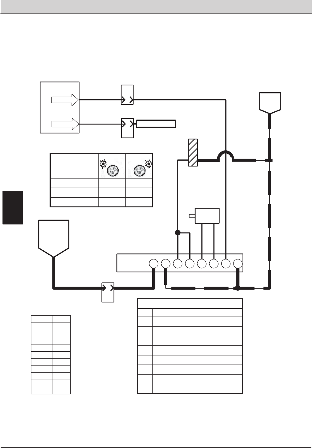
114 T20 Service Information (5-2017)
ELECTRICAL TROUBLESHOOTING
Wiring Color Codes
(Unless otherwise marked)
Touch Panel /
Control Board
11
18
PIN P2-24
B
6
PIN
J-10
8
PIN
E
J-12
ENGINE HARNESS
CONNECTORS
Governor Speed “A”
Governor Speed “B”
NO CONNECTION
GOVERNOR
A
10
PIN
33
J-11
ENGINE HARNESS
CONNECTOR
CONTROLLER A
SWITCHED
BATTERY
POSITIVE
FROM
SHUTDOWN
RELAY M6C
3
3BCDEFGH
BATTERY
NEGATIVE
PIN P2-25
THROTTLE
ACTUATOR
+-
MAGNETIC
PICK-UP
(ENGINE SPEED)
SENSOR
13/BLK
13/BLK13/BLK
29
29
13/BLK
6059
61 61
61
29
E
ENGINE
SPEED
CHART
Low Engine
Speed
High Engine
Speed
Engine RPM 1350 2400
Voltage Speed “A” 5 VDC 0 VDC
Voltage Speed “B” 0 VDC 0 VDC
Right Most Digit
of Wir e N umber
Color of Wire
0 Tan
1 Pink
2 Brown
3 Orange
4 Yellow
5 Green
6 Blue
7 Purple
8 Gray
9 White
Governor Controller Pin Chart
pin description
AINPUT – Battery Positive
BINPUT – Battery Negative
CINPUT – Engine Speed Sensor
DINPUT – Engine Speed Sensor
EOUTPUT – Throttle Actuator (PWM)
FOUTPUT – Throttle Actuator
GINPUT – Engine Speed Selection “A”
HINPUT – Engine Speed Selection “B”
T20 Engine Speed Control
(Diesel)
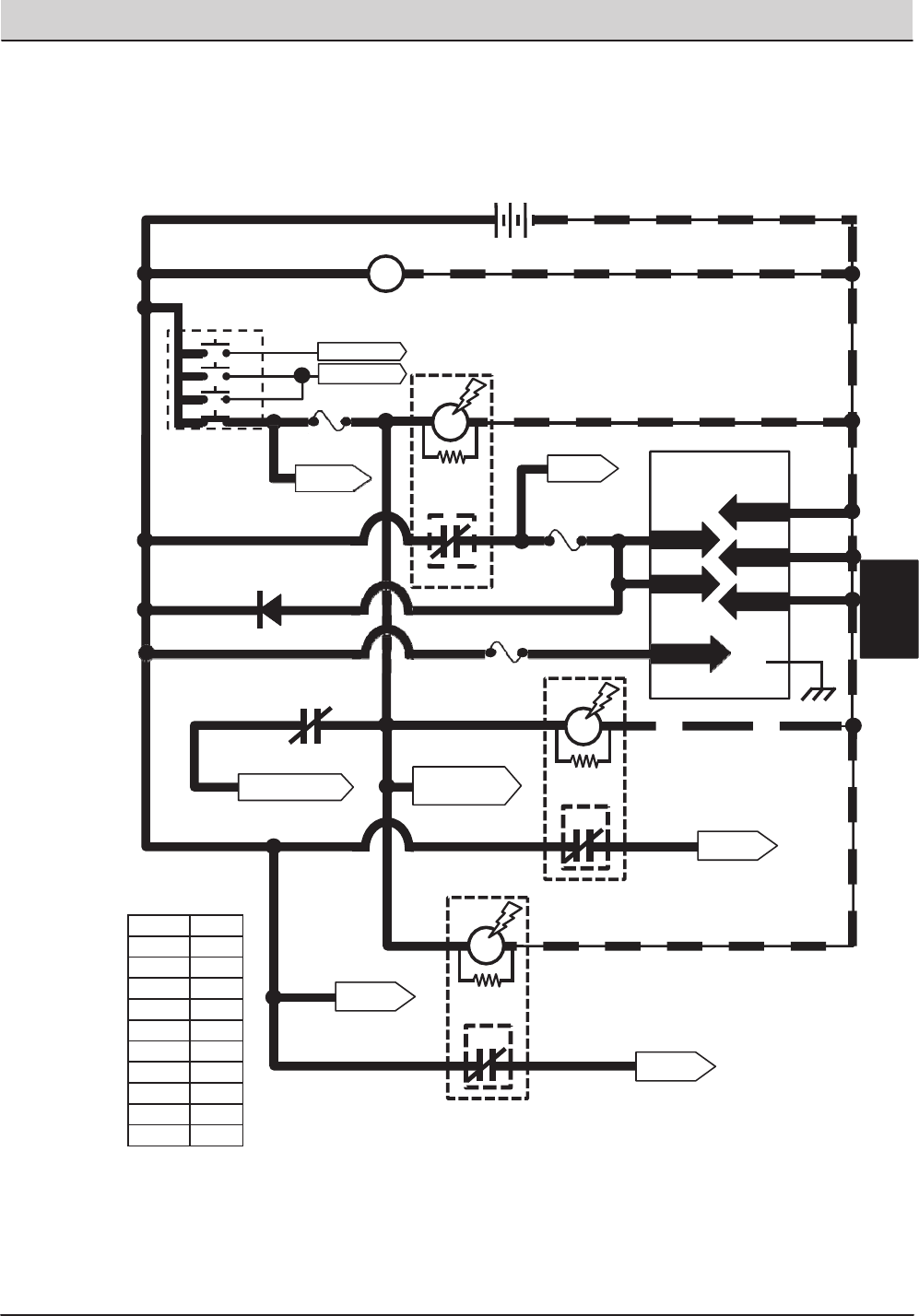
T20 Service Information (5-2017) 115
ELECTRICAL TROUBLESHOOTING
1/RED 13/BLK
13/BLK
13/BLK
13/BLK
+-
12 VDC
KEY SWITCH
RUN
ALTERNATOR
+-
Touch Panel /
Control Board
GREEN JUMPER WIRE1/RED
4
1/RED1/RED 6
PIN P2-33
PIN P2-34
PIN P2-35
Wiring Color Codes
(Unless otherwise marked)
Right Most Digit
of WireNumber
Color of Wire
0 Tan
1 Pink
2 Brown
3 Orange
4 Yellow
5 Green
6 Blue
7 Purple
8 Gray
9 White
TO FUSES
7 & 8
SHUTDOWN RELAY
CONTACTS
3
8
8
13/BLK
13/BLK
M6C
(NormallyCLOSED)
To Engine Harness
Connector Pin P1-A
TO FUSE
6
1/RED
14
1/RED
PIN P2-1
PIN P2-2
M1B
AUX. 1
RELAY
M1A
8
3
8
6
14
13/BLK
86 85
30 87
M2B
AUX. 2
RELAY
M2A
86 85 13/BLK
30 587
4
14
D-2
14
TO FUSES
9 &12
1/RED
1/RED
S1
30 50
17
19
ACC
2
42
42
To M7 StartRelay
To GlowPlug
Circuit (Diesel only)
FUSE 1 8
15 AMP
FUSE 5 14
15 AMP
5
To LP1 Alternator
Lamp & Parking
Brake Lamp
M8B
AUX. 3
RELAY
M8A
86 85
30 587
1/RED
1/RED
813/BLK
13/BLK
TO FUSES
13 & 14
27
FUSE 10
15 AMP
1/RED 81 PIN P2-3
1/RED1/RED
TO FUSES
2,3, & 11
1/RED
STATIC
GROUND
PIN P1-23
105
T20 Key On Power Distribution
Conditions: Key On, Engine Off
E
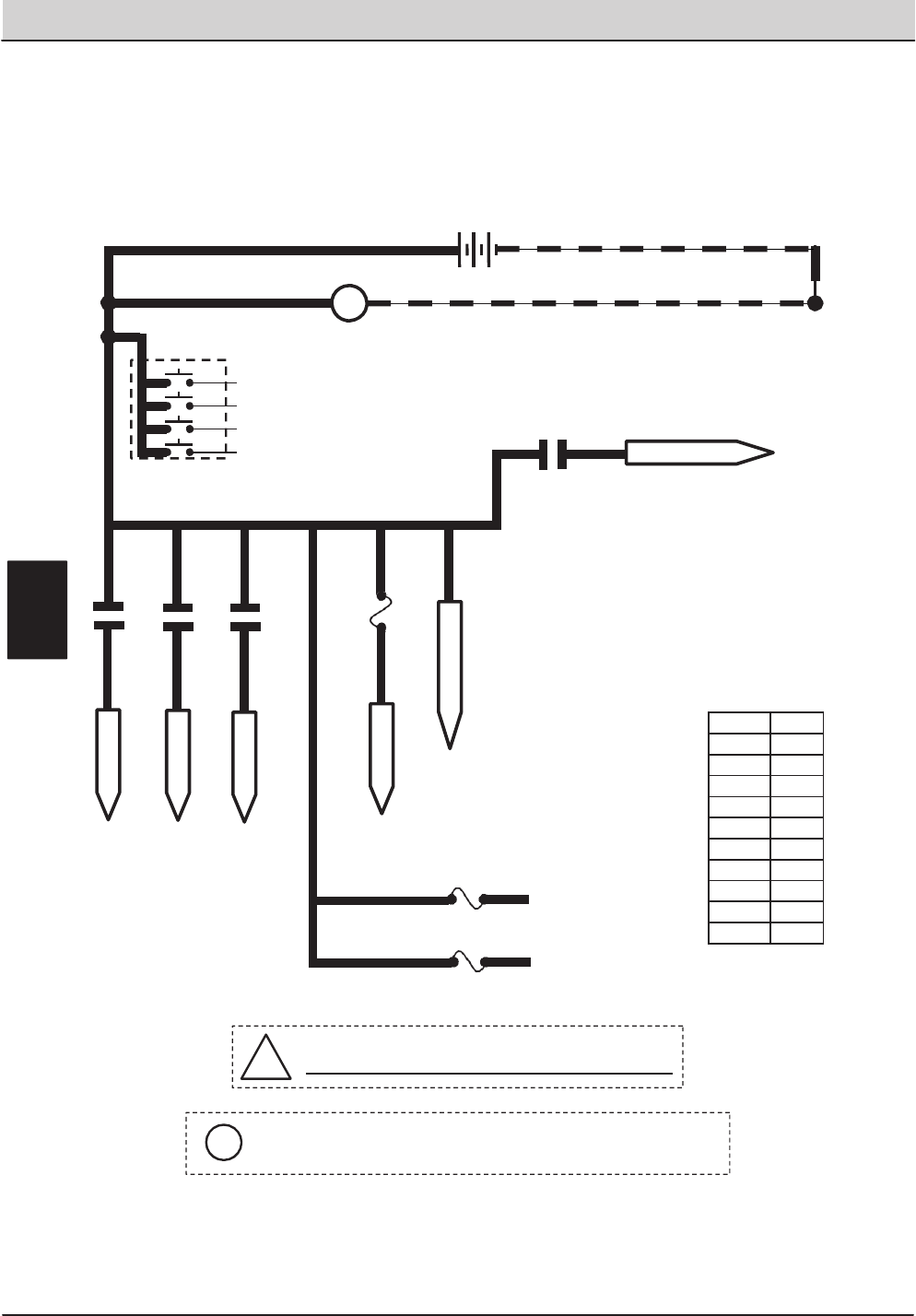
116 T20 Service Information (5-2017)
ELECTRICAL TROUBLESHOOTING
1/RED 13/BLK
+-
12 VDC
ALTERNATOR
+-
1/RED
GREEN JUMPER WIRE1/RED
1/RED
Wiring Color Codes
(Unless otherwise marked)
!Be cautious when working near Control Board -
Battery voltage is always present, even with Key OFF
KEY SWITCH
OFF
Right Most Digit
of Wir e N umber
Color of Wire
0 Tan
1 Pink
2 Brown
3 Orange
4 Yellow
5 Green
6 Blue
7 Purple
8 Gray
9 White
30
50
17
19
ACC
Pin P2-3 supplies power to the on-board clock only.
Disconnecting battery, removing Fuse 10, or removing connector
P2 from Control Board will require the clock to be reset.
i
1/RED
1/RED
1/RED
1/RED 128/GRY
FUSE-2
15A
Aux. 2 Relay
Aux. 3 Relay
Fuse 11
15A
128 B+
Extra Fused B+
1 (UNSWITCHED B+)
SEE DIODE D-2
27 (AUX #3)
27 / PUR
5 (AUX #2)
5 / GRN
6 (AUX #1)
6 / BLU
M/7B
START RELAY
77/PUR
1/RED
1/RED
1/RED
Aux. 1 Relay
FUSE-3
15A
122/BRN
25/GRN
B+ WHILE CRANKING
T20 Key Off Power Distribution
Conditions: Key Off
E
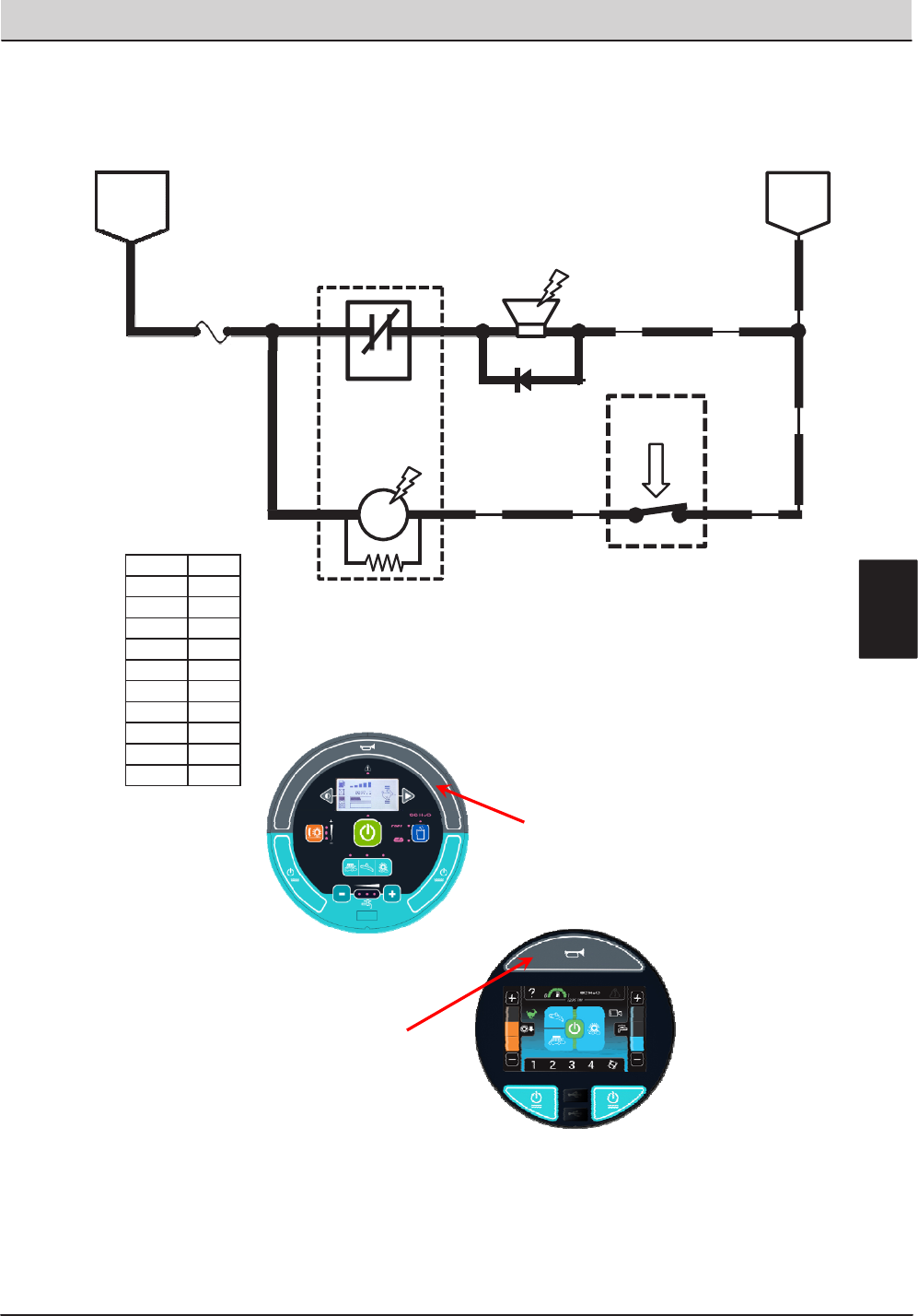
T20 Service Information (5-2017) 117
ELECTRICAL TROUBLESHOOTING
25 30
1/RED FUSE 3
15 AMP
HORN
RELAY
23 13/BLK
25
S-22
HORN
SWITCH
OPEN = HORN OFF
CLOSED = HORN ON
92 13/BLK
D1
23 13/BLK
Wiring Color Codes
(Unless otherwise marked)
M5A
UN-
SWITCHED
BATTERY
POSITIVE
BATTERY
NEGATIVE
M5B
HORN
86 85
87
Right Most Digit
of Wir e N umber
Color of Wire
0 Tan
1 Pink
2 Brown
3 Orange
4 Yellow
5 Green
6 Blue
7 Purple
8 Gray
9 White
E
T20 Horn
Conditions: Key On, Switch Activated
HORN
HORN

118 T20 Service Information (5-2017)
ELECTRICAL TROUBLESHOOTING
ON
Lower Valve ON
ON
Speed
Valve ON
ON
ON
Valve ON
Valve ON
Valve ON
Enable Valve, Air Pump &
ON
ON
FaST Detergent Pump ON
Lamp
E = Input required to ENABLE output D = Input req
ponent #
T20 Enable/Disable Chart
Notes
Propel required to to get full
operational down pressure
Propel required to to get full
operational down pressure
Propel required to to get full
operational down pressure
Turns OFF automatically if
not required (SV-7 is
required for all hydraulic
functions EXCEPT sweep
and scrub vacuum fans)
If low oil pressure, engine
ECM will shutdown the
engine after a time delay
Touch Panel Input(s)
Required to DISABLE
OneStep Scrub OFF;
Squeegee/Scrub Vacuum OFF;
Low Engine Speed Selected
OneStep Scrub OFF; Low Engine
Speed Selected
OneStep Scrub OFF; Low Engine
Speed Selected
OneStep Scrub OFF; Low Engine
Speed Selected; Squeegee/Scrub
Vacuum OFF
OneStep Scrub OFF; Low Engine
Speed Selected
Refer to Notes
OneStep Scrub OFF; Low Engine
Speed Selected; Side Brush OFF
OneStep Scrub OFF; Low Engine
Speed Selected; Side Brush OFF
OneStep Scrub OFF; Low Engine
Speed Selected; Side Brush OFF
Touch Panel Input(s)
Required to ENABLE
OneStep Scrub ON;
Squeegee/Scrub
Vacuum ON
OneStep Scrub ON
OneStep Scrub ON
OneStep Scrub ON;
Squeegee/Scrub
Vacuum ON
OneStep Scrub ON
Turning ON Any Touch
Panel Function OR
Selecting High Engine
Side Brush ON (after
OneStep Scrub ON)
Side Brush ON (after
OneStep Scrub ON)
Side Brush ON (after
OneStep Scrub ON)
Propel
Pedal
Sensor
NEUTRAL
n/a
P1-1
Refer to
Notes
Refer to
Notes
E
Refer to
Notes
Propel Pedal
Sensor
REVERSE
n/a
P1-1
E
see notes
E
see notes
D
E
see notes
E
E
E
Propel Pedal
Sensor
FORW ARD
n/a
P1-1
E
see notes
E
see notes
E
E
see notes
E
E
E
Impact
Sensor
Closed
S-23
P1-21
Hydraulic Oil
Temperature
Sensor above
230F
S-20
P1-17
E
Soution
Tank
Empty
Switch
Closed
S-19
P1-11
E
Clogged
Hydraulic
Filter Switch
Closed
S-17
P1-15
E
Recovery
Tank Half
Full Switch
Closed
S-16
P1-14
D
E
ES only
Recovery
Tank Full
Switch
Closed
S-15
P1-13
D
D
D
D
D
D
D
D
D
D
D
D
D
D
D
Solution
Tank Full
Switch
Closed
S-14
P1-12
D
D
ES only
Fuel Pressure
Switch Closed
(LPG)
S-8
P1-4
E
when low
Fuel Level
Sender (Gas,
Diesel)
S-7
P1-4
E
when low
Input
pin
P2-28
P2-4
P2-5
P2-6
P2-5
P2-8
P2-9
P2-11
P2-12
P2-9
P2-13
P2-14
P2-19
P2-22
P2-23
P2-26
P2-20
P2-17
P2-18
P2-21
P2-29
P2-27
P2-24
P2-25
com
SV-1
SV-2
SV-3
SV-4
SV-6
SV-7
SV-8
SV-10
SV-11
SV-12
SOL-1
SOL-2
SOL-3
SOL-4,
M11
SOL-5
SOL-6
SOL-7
M4A
M6A
n/a
n/a
n/a
n/a
n/a
M20 Control Board
Inputs and the Outputs
they Control
Output
Scrub Vacuum Fan Valve
Main Brush Head Down
Pressure Valve ON
Main Brush Head Lower
Valve ON
Rear and Side Squeegees
Main Brushes Spin Valve
ON
Hydraulic Enable Valve
Side Brush Spin Valve ON
Side Brush Down Pressure
Side Brush Lower Valve
Side Brush Extend Valve
Auto-Fill Solution Tank
Auto-Fill Recovery Tank
Main Brushes Solution
ES Pump ON OR FaST
Water Pump Relay ON
FaST High Flow Valve ON
FaST Side Brush Valve
Side Brush Solution Valve
Reverse Propel Relay ON
Shut Down Relay ON
Detergent Pump ON
OR
Audible Alarm
Low Engine Oil Pressure
Governor Speed Bit "A"
Governor Speed Bit "B"
E
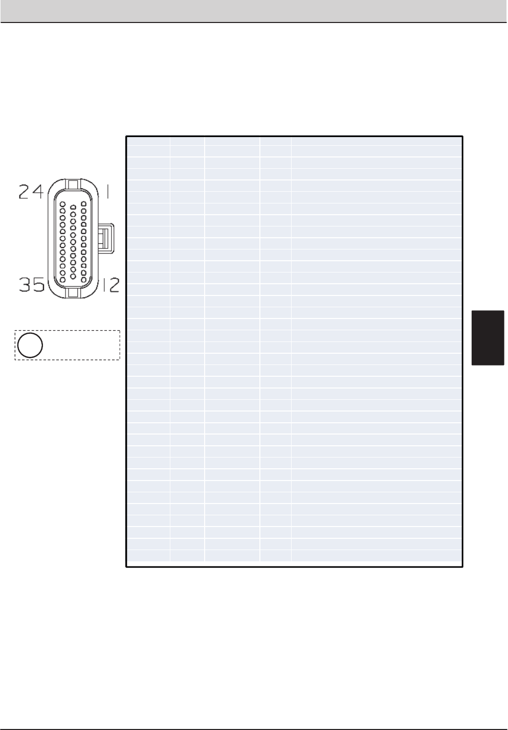
T20 Service Information (5-2017) 119
ELECTRICAL TROUBLESHOOTING
T20 Control Board Connectors
P1 Connector
Viewed from wire
side of connector
iE
Socket# Wire# Color Type GoesTo:
P1‐1 91 Pink Input Forward/ReversePropelSensor
P1‐2 150 Tan Input ec‐H20GreenLED
P1‐3 89 White Input Switch6HopperPosition
P1‐4 30 Tan Input FuelSensor
P1‐5 129 White Input ThermalSentry
P1‐6 39 White Input ShakerSwitch(Partial)
P1‐7 35 Green Input HopperUp/DnSwitch(SignalDown)
P1‐8 36 Blue Input HopperUp/DnSwitch(SignalUp)
P1‐9 42 Brown Input HopperDoorSwitch(SignalDoorOpen)
P1‐10 43 Orange Input HopperDoorSwitch(SignalDoorClose)
P1‐11 177 Purple Input SolutionTankEmpty
P1‐12 44 Yellow Input SolutionTankFull
P1‐13 45 Green Input RecoveryTankFull
P1‐14 46 Blue Input RecoveryTank1/2Full
P1‐15 90 Tan Input CloggedHydraulicFilter
P1‐16 48 Gray Input CloggedShakerFilter(N.O./Closed=Clogged)
P1‐17 78 Gray Input HydraulicTempSensor
P1‐18 12 Brown Input EngineTemp.DSL
P1‐19 9 White Input N.O.OilPressure
P1‐20 149 White Input ec‐H20RedLED
P1‐21 94 Yellow Input ConnectstoCESeatSwitchHarness
P1‐22 186 Blue Input To:EngineECM
P1‐23 187 Purple Input To:EngineECM
P1‐24 22 Brown Input BrakeSitchSense
P1‐25 ‐‐ CAN+/Yellow ‐‐ UserInterfaceModule
P1‐26 ‐‐ CAN‐/Green ‐‐ UserInterfaceModule
P1‐27 XXX XXX XXX XXX
P1‐28 XXX XXX XXX XXX
P1‐29 10 Tan Input To:EngineECM
P1‐30 XXX XXX XXX XXX
P1‐31 XXX XXX XXX XXX
P1‐32 7 Purple Input AlternatorCharging
P1‐33 XXX XXX XXX XXX
P1‐34 16 Blue Output FlybackNet17
P1‐35 17 Purple Output Flyback Net18
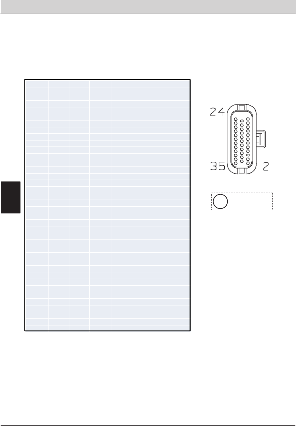
120 T20 Service Information (5-2017)
ELECTRICAL TROUBLESHOOTING
T20 Control Board Connectors
P2 Connector
Viewed from wire
side of connector
i
Socket# Wire# Color Type GoesTo:
P2‐1 14 Yellow 12VDC Board
P2‐2 14 Yellow FlybackNet:14
P2‐3 49 White Output MainBrushOn
P2‐4 57 Purple Output MainBrushPattern(PWM)
P2‐5 58 Gray Output MainBrushDown
P2‐6 59 White Output SqueegeesDown
P2‐7 60 Tan Output HopperUp
P2‐8 61 Pink Output EnableValve
P2‐9 50 Tan Output SideBroomExtend
P2‐10 63 Orange Output SweepVacFanOn
P2‐11 64 Yellow Output SideSrubPattern(PWM)
P2‐12 66 Blue Output SideBroomDown
P2‐13 65 Green Output Opt:AutoFillSol
P2‐14 67 Purple Output Opt:AutoFillRec
P2‐15 68 Gray Output HopperDoorOpen
P2‐16 69 White Output ShakerRelay
P2‐17 70 Tan Output ReverseRelay
P2‐18 71 Pink Output ShutdownRelay
P2‐19 72 Brown Output MainScrubWaterValve
P2‐20 181 Pink Output SideBrushWaterValve
P2‐21 74 Yellow Output DetergentPump(PWM)
P2‐22 75 Green Output ESPump(Opt.)
P2‐23 79 White Output
FastHighFlowValve/FastPump
(Opt.)
P2‐24 11 Pink Output SpeedBitA
P2‐25 18 Gray Output SpeeedBitB
P2‐26 80 Tan Output FastSideBrush
P2‐27 92 Brown Output HornRelay
P2‐28 56 Blue Output ScrubVacFanOn
P2‐29 182 Brown Output AudibileAlarm
P2‐30 62 Brown Output SideScrubOn
P2‐31 53 Orange Output HopperDown
P2‐32 138 Green Output HopperLatchSol.
P2‐33 13 Black Output Ground1
P2‐34 13 Black Output Ground2
P2‐35 13 Black Output Ground3
E
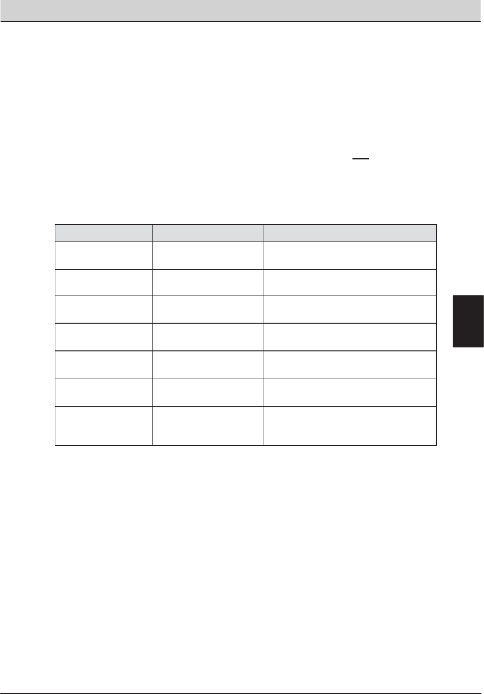
T20 Service Information (5-2017) 121
ELECTRICAL TROUBLESHOOTING
T20 Fault Indicators
The following table describes fault codes communicated to the operator. A fault code is
indicated by blinking a Fault LED (red), sounding an alarm, and also by displaying the fault
name on the LCD. Faults can be cleared when they are no longer present and one of the
action buttons (i.e. One-Step) is depressed. If there is more than one fault, they are displayed
for about a second one after the other.
Fault LCD Display Description
Hydraulic Filter
Clogged
F3: CLOGGED HYD Indicates the hydraulic filter is clogged.
Solution Tank empty F6: SOL. TANK E Indicates the solution tank is empty.
Recovery Tank Full F7: REC. TANK FULL Indicates the recovery tank is full and
shuts down the entire Scrub system.
High Engine
Temperature
F8: HIGH ENG TEMP Indicates high engine temperature.
High Hydraulic
Temperature
F9: HIGH HYD TEMP Indicates excessive hydraulic
temperature
Low Fuel F10: LOW FUEL Low fuel indicator (blinking lowest fuel
gauge block).
Squeegee
Disconnected
(Option)
F11: OPEN SCB VAC Indicates squeegee may have broken
free.
E

122 T20 Service Information (5-2017)
ELECTRICAL TROUBLESHOOTING
T20 Condition & Warning Indicators
The following table describes displayed conditions or warnings. If a condition is sensed,
the condition or warning code will be displayed on the LCD. Conditions are typically
caused by activating buttons that are unavailable. For example: the Sweep vacuum fan
is unavailable when the scrub functions are active.
Condition LCD DISPLAY Description
FaST system is selected by
the operator and the
machine is not configured
with the FaST option.
C3: NO FAST MODE Only machines with the FaST
system installed (and
programmed to be FaST
machines) can turn ON the
FaST system.
ES system is selected by the
operator and the machine is
not configured with the ES
option.
C4: NO ES MODE Only machines with the ES
system installed (and
programmed to be ES
machines) can turn ON the ES
system.
FaST or ES system is
selected by the operator and
the machine is not
configured with the ES or
FaST option.
C5: NO ES/FAST Only machines with the ES or
FaST system installed (and
programmed to be ES or Fast
machines) can turn ON the ES
or FaST system.
Side Brush button is
activated alone without 1-
STEP Sweep/Scrub.
C6: NO SIDE BRUSH The T20 machine is NOT
programmed to operate with
only the side brush ON.
E

T20 Service Information (5-2017) 123
HYDRAULIC TROUBLESHOOTING
HYDRAULIC TROUBLESHOOTING
T20 SERVICE INFORMATION Hydraulic Troubleshooting
HYDRAULIC
Troubleshooting Information
• BEFORE CONDUCTING TESTS:
* Read and Follow ALL Safety Warnings and
Precautions as mentioned at the beginning of this
manual
* Engine & Hydraulic Oil Must Be At Normal
Operating Temperatures after Running Machine
and Hydraulics a Minimum of 5 Minutes
* Examine Machine For Any Linkage Binding or
Mechanical Problems
• DURING TESTS:
* Call Technical Services if Diagnostic Time
Exceeds One Hour With Unknown Cause or
Course of Action
* Maintain Normal Main Brush Pressure as Listed in
Operator’s Manual
NOTE: Troubleshooting charts may be shown with optional equipment. The optional equipment may
not be specified in these charts. Some machines may not be equipped with all components shown.

124 T20 Service Information (5-2017)
HYDRAULIC TROUBLESHOOTING
Commonly Used Hydraulic Symbols
Lines Connected
Together
Lines Not
Connected
Together
Component
is Energized
Information
!
Warning!
Assembly
Pressure / Flow Line
Return or Low Pressure Line
Active Pilot Port Line
Inactive Pilot Port Line
Case Drain Line
Suction Line
Component
is Rotating
Hydraulic
Flow
Hydraulic
Pump
Hydraulic
Motor
Relief Valve
Hydraulic
Cylinder
Hydraulic
Solenoid Valve
Pressure
Reducing Valve
Check
Valve
Spring Loaded
Check Valve
No ConnectionQuick Connect
Test Port
Restrictor or
Orifice
Oil Tank or
Reservoir
Oil Cooler or
Heat Exchanger
Oil Filter
With Bypass
Pilot Port
Check Valve
Variable
or PWM
Indicates Energized Solenoid Valve Coil
EXAMPLES
Circled envelope is
valve position for indicated
hydraulic circuit
SV19
A
B
SV25
Arrow indicates a
PWM (Pulse Width
Modulated) valve
SV14 SV7
Energized
Coils
Non-Energized
Coils
T20 General Information
i
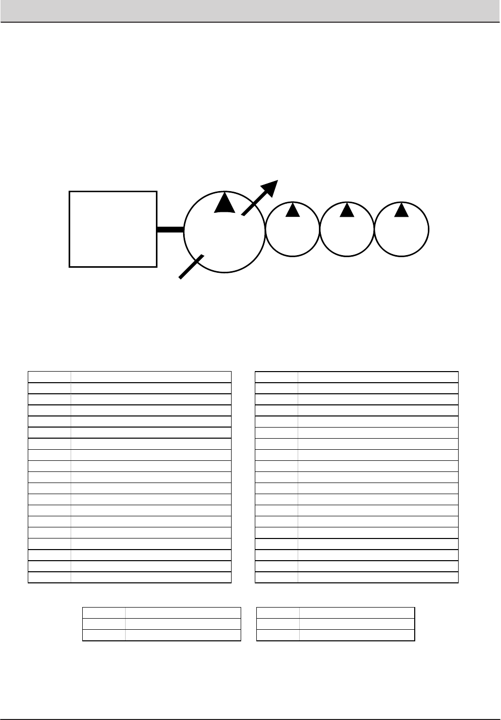
T20 Service Information (5-2017) 125
HYDRAULIC TROUBLESHOOTING
T20 Hydraulic Pump Flow Rates (typical)
ENGINE @
2400 RPM
10 GPM
(37.9 LPM)
4 GPM
(15.1 LPM)
6 GPM
(22.7 LPM)
PROPEL
PUMP
ACCESSORY PUMPS
PUMP
1
PUMP
2
PUMP
3
T20 General Information
AUX Auxiliary
CIR Cubic Inch Displacement per Revolution
CK Check Valve
CM Centimeters
CONV Conveyor
CU Cubic
CV Control Valve
CYL Cylinder
DC Disconnect Coupler (Hydraulic)
DC Direct Current (Electrical)
E Engine (Combustion)
FLTR Filter
GPM Gallons Per Minute
HTX Heat Exchanger
IN Inches
LH Left Hand
LPM Liters Per Minute
LS Load Sense
M Motor (Combustion)
MFLD Manifold
MTR Motor (Hydraulic)
OR Orifice
PC Pilot Port Check Valve
PMP Pum p
PR Pressure Relief Valve
PSI Pounds Per Square Inch
PTO Power Take Off
PWM Pulse Width Modulation
RES Reservoir
RH Right Hand
RPM Revolutions Per Minute
RV Relief Valve
SC Spring Loaded Check Valve
STRN Strainer
SV Solenoid Valve
SW Switch
TV Throttle Valve
V Volts
C Hydraulic Cylinder Connection
G Test Port
LS Load Sense Port
M Hydraulic Motor Connection
P Pump Connection
R or T Return Port (To Tank)
Commonly Used Abbreviations
Typical Hydraulic Manifold Port Markings
12.5 GPM
(47.3 LPM)
maximum
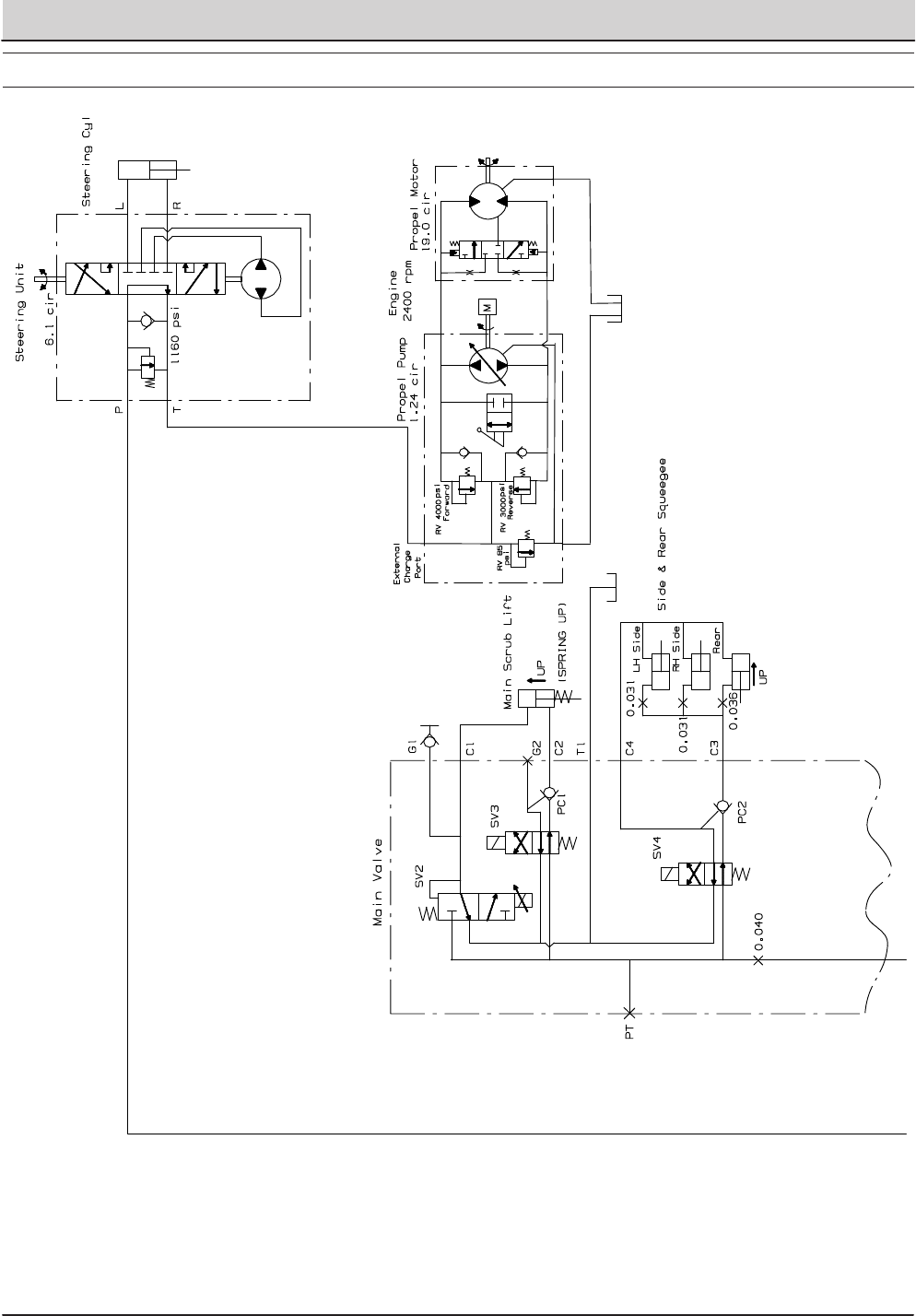
126 T20 Service Information (5-2017)
HYDRAULIC TROUBLESHOOTING
HYDRAULIC SCHEMATIC
STANDARD PARTS
T20 Gas/LPG 9016201 (12−2016)
2‐104
Fig. 51 − Hydraulic Schematic
1
2
354520 − T20
Home
Find...
Go To..
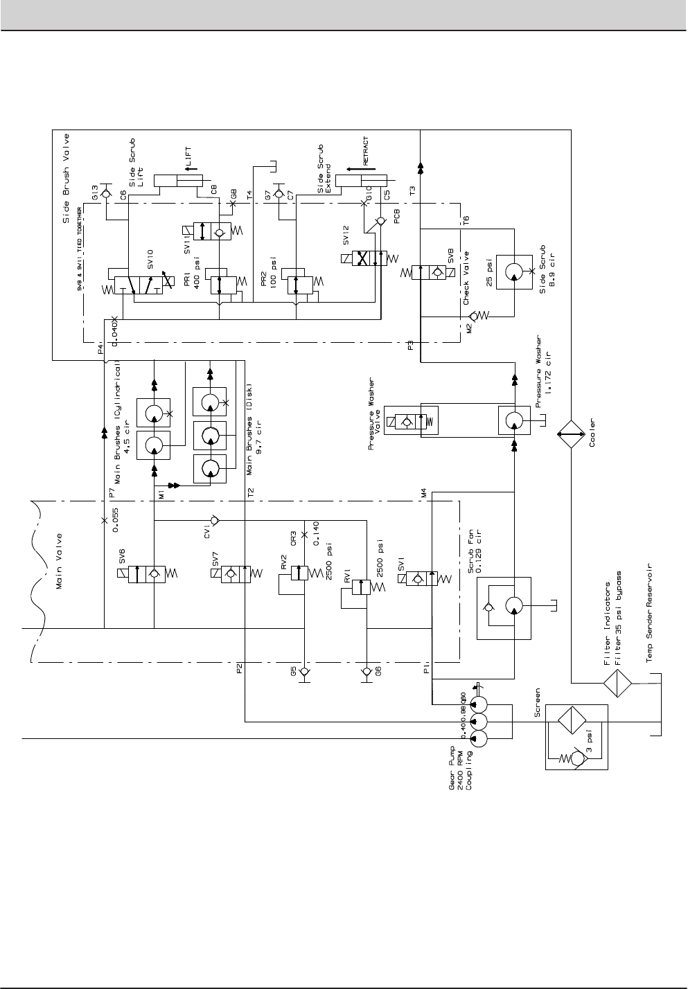
T20 Service Information (5-2017) 127
HYDRAULIC TROUBLESHOOTING
STANDARD PARTS
2‐105
T20 Gas/LPG 9016201 (12−2016)
Fig. 51 − Hydraulic Schematic
1
2
354520 − T20
Home
Find...
Go To..
128 T20 Service Information (5-2017)
HYDRAULIC TROUBLESHOOTING
Component /
System Function Tes t
Po r t
Test Port
Location Energized Coil(s) Notes
Manifold(s)
containing
Solenoid
Valve(s)
Location Feed Port Exit Port Relief V alve
in c ircuit
Relief Valve
Pressure
Setting (PSI)
Notes
Down G1
S
cru
b
Manifold SV2, SV3, SV7* C1 C2
Up G5 N/A SV7*
C2 C1
Down G5
S
cru
b
Manifold SV4, SV7* C4 C3
Up G5 N/A SV7*
C3 C4
Main Brushes Operate G5
Scrub
Manifold SV6, SV7*
Use Manual Mode during testing to
obtain full down pressure; SV3 and SV6
are tied together electrically
Scrub
Manifold
Left side, engine
compartment,
beside vacuum fan
M1 Tank RV2 2500
Operating Flow from
accessory Pump # 1
(inner most pump)
Scrub Fan Operate G6
Scrub
Manifold SV1 Scrub
Manifold
Left side, engine
compartment,
beside vacuum fan
Accessory
Pump # 2 P3 RV1 2500
Operating Flow from
accessory Pump # 2
(middle pump)
Side Brush Operate G6
Scrub
Manifold SV8 Use Manual Mode during testing Side Brush
Manifold
Left front corner of
frame M2 T6 RV1 2500
Operating Flow from
accessory Pump # 2
(middle pump)
Up G5 SV7*
C8 C6
Down G13 SV10, SV11, SV7*
C6 C8
Retract G5 SV7*
C5 C7
Extend G7 SV12, SV7*
C7 C5
* SV7 is Enable Solenoid for the given functions
2500
Operating Flow from
accessory Pump # 1
(inner most pump)
2500
Operating Flow from
accessory Pump # 1
(inner most pump)
Left side, engine
compartment,
beside vacuum fan
Use Manual Mode during testing
Side
V a l ve
Side Brush
Manifold
Left front corner of
frame RV2
Operate Side Brush up and down using
Manual Mode--Watch change in
pressure on G5 and/or G13; SV8 and
SV11 tied together electrically
RV2
Side Brush
Scrub Head
Squeegees,
Side and Rear
Operating Flow from
accessory Pump # 1
(inner most pump)
RV2 2500
Left side, engine
compartment,
beside vacuum fan
Scrub
Manifold
SV2 is PWM controlled; Down pressure
varies with current to SV2; SV3 and
SV6 are tied together electrically
Scrub
Manifold
T20 Operating Matrix
T20 Service Information (5-2017) 129
HYDRAULIC TROUBLESHOOTING
T20 Option Components
E = Electrical Component
H = Hydraulic Component
The following chart lists various options and the electrical and/or hydraulic components
that are associated with the option. Refer to the “notes” section for any components that
are deleted from a standard machine in order to have the installed option.
option added components E or H component # notes
Side Brush ON Solenoid Valve
E,H
SV-8
Side Brush Pressure Solenoid Valve
E,H
SV-10
Side Brush Down Solenoid Valve
E,H
SV-11
Side Brush Extend Solenoid Valve
E,H
SV-12
FaST Side Brush Valve
E
SOL-6
Side Brush Water Valve
E
SOL-7
Side Brush Manifold
H
x
Side Brush Lift Cylinder
H
x
Side Brush Extend Cylinder
H
x
Side Brush Motor
H
x
Solution Tank Auto Fill Water Valve
E
SOL-1
Recovery Tank Auto Fill Water Valve
E
SOL-2
Solution Tank Full Switch
E
S-14
Recovery Tank Half Full Switch
E
S-16
Detergent Pump
E
x
ES Pump
E
x
Spray Hose Pump
E
x
Spray Hose Relay
E
M12
Spray Hose Switch
E
S-25
ES
(Extended Scrub)
If machine has ES option, the following
components will not be on the
machine: FaST Water Pump, FaST
Water Pump Relay (M11), FaST
Detergent Pump, FaST Air Pump,
FaST Enable Valve (SOL-4), FaST
High Flow Valve (SOL-5), FaST Side
Brush Valve (SOL-6)
Spray
Hose Side Brush
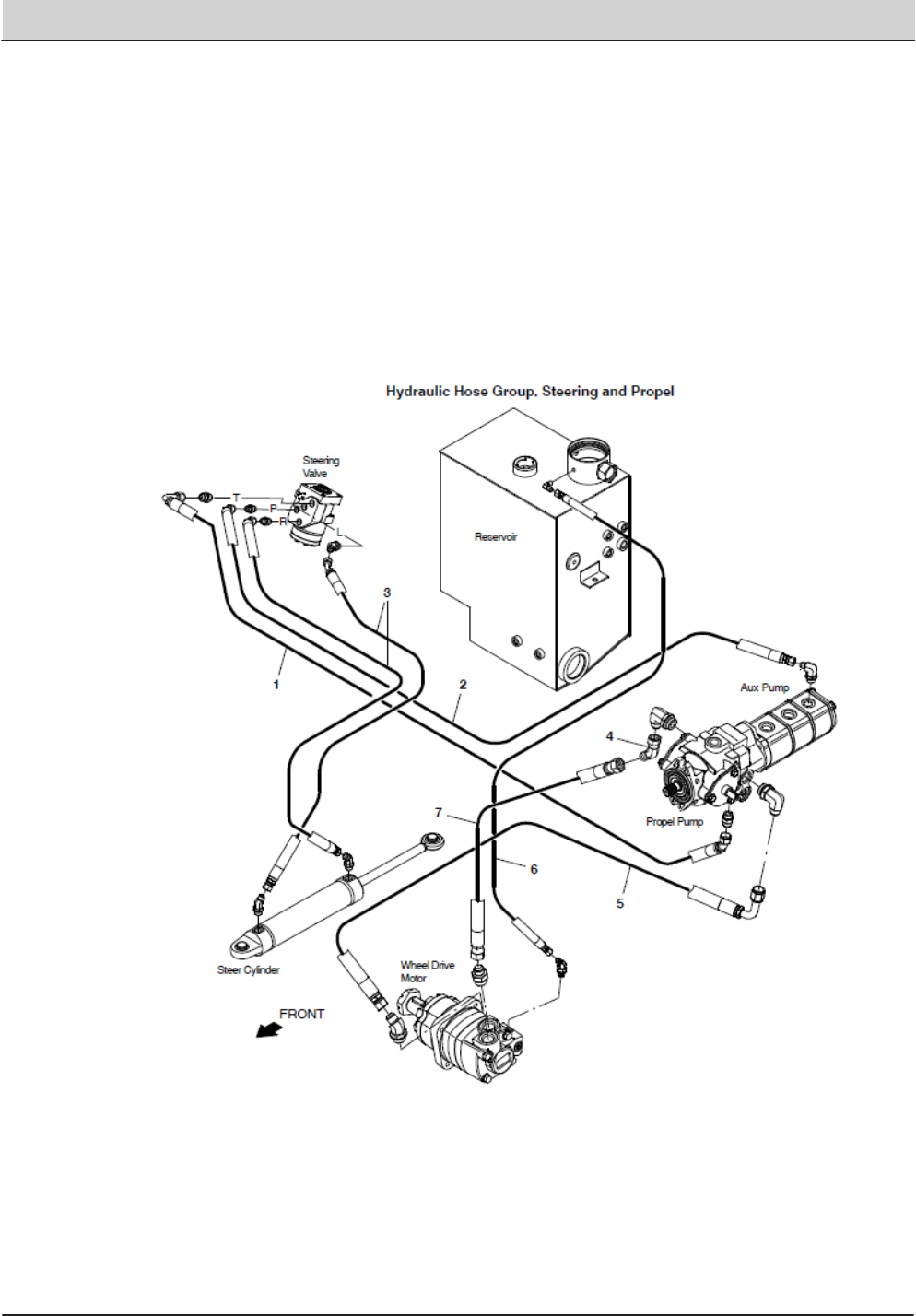
130 T20 Service Information (5-2017)
HYDRAULIC TROUBLESHOOTING
Hose Group: Steering and Propel
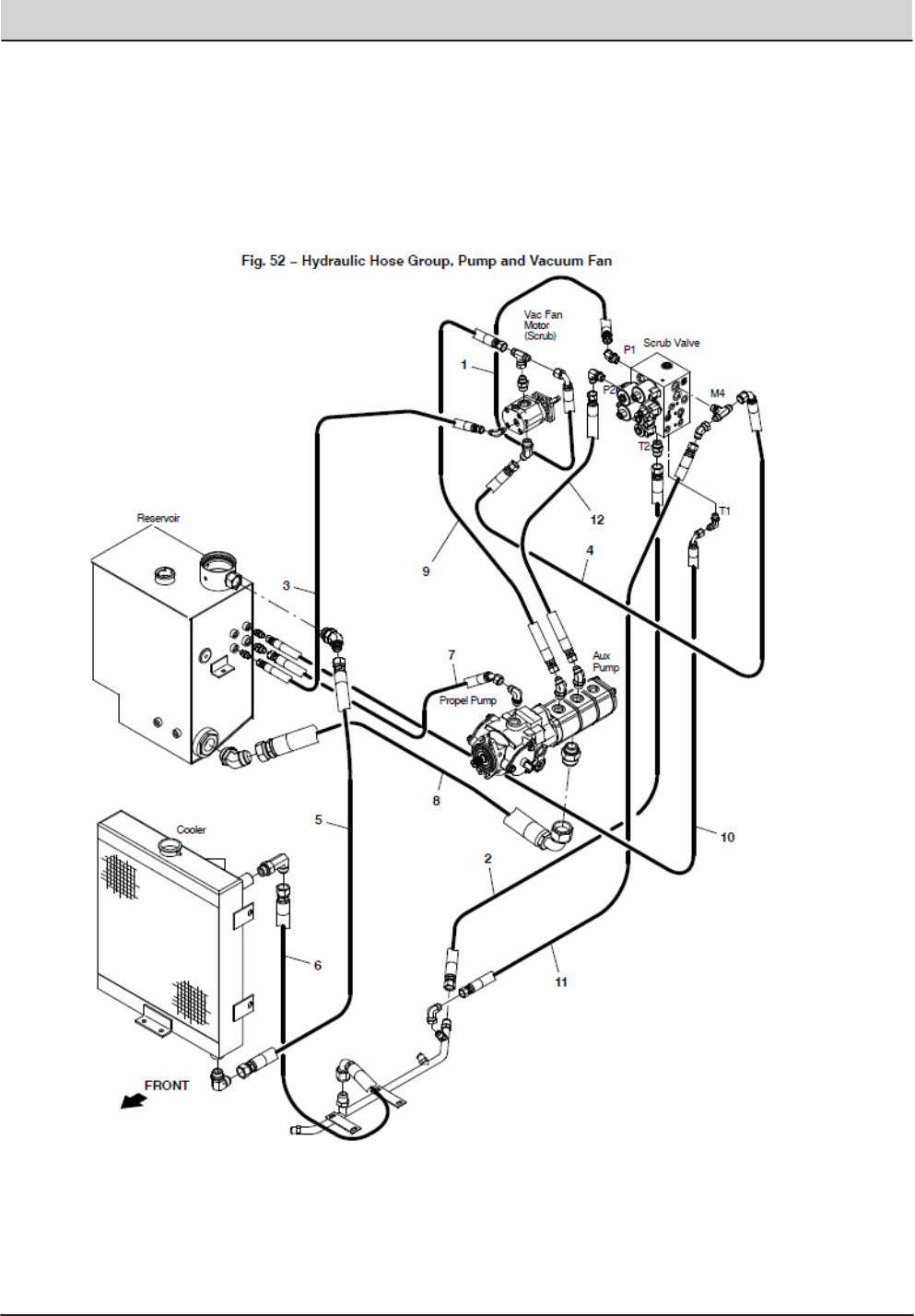
T20 Service Information (5-2017) 131
HYDRAULIC TROUBLESHOOTING
Hose Group: Pump and Vacuum Fan
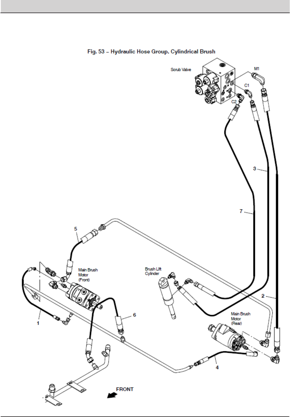
132 T20 Service Information (5-2017)
HYDRAULIC TROUBLESHOOTING
Hose Group: Cylindrical Brush
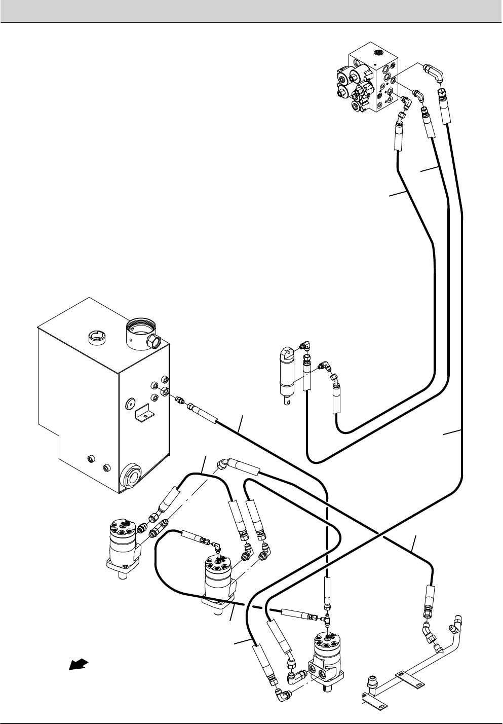
T20 Service Information (5-2017) 133
HYDRAULIC TROUBLESHOOTING
STANDARD PARTS
T20 Gas/LPG 9016201 (8−2016)
2‐112
Fig. 55 − Hydraulic Hose Group, Disk Brush
Scrub Valve
Main Brush
Motor
(Right)
Main Brush
Motor
(Left)
Brush LIft
Cylinder
M1
C1
C2
Main Brush
Motor
(Center)
Reservoir
1
2
3
4
5
6
7
8
FRONT
Home
Find...
Go To..
Hose Group: Disk Brush
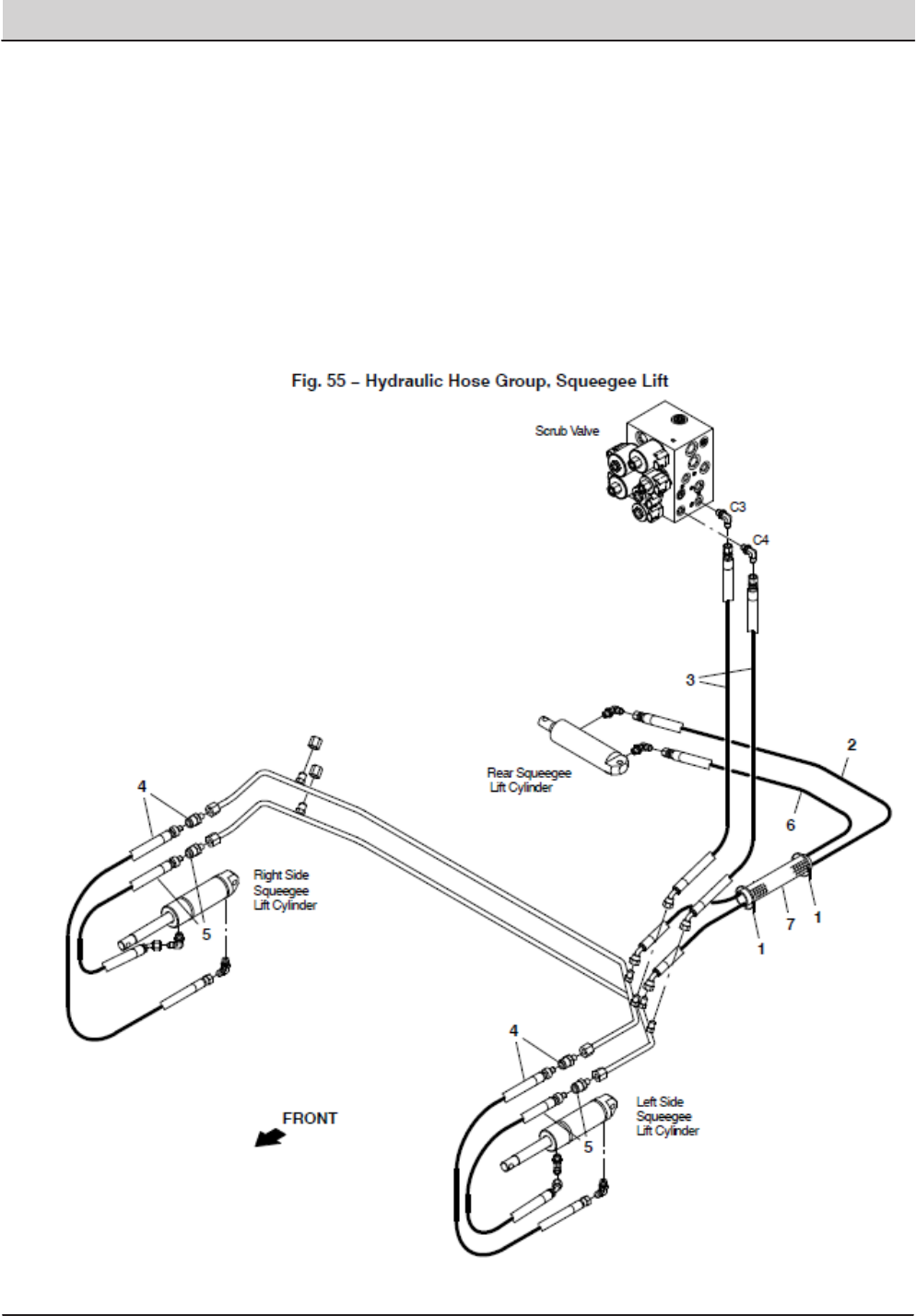
134 T20 Service Information (5-2017)
HYDRAULIC TROUBLESHOOTING
Hose Group: Squeegee Lift
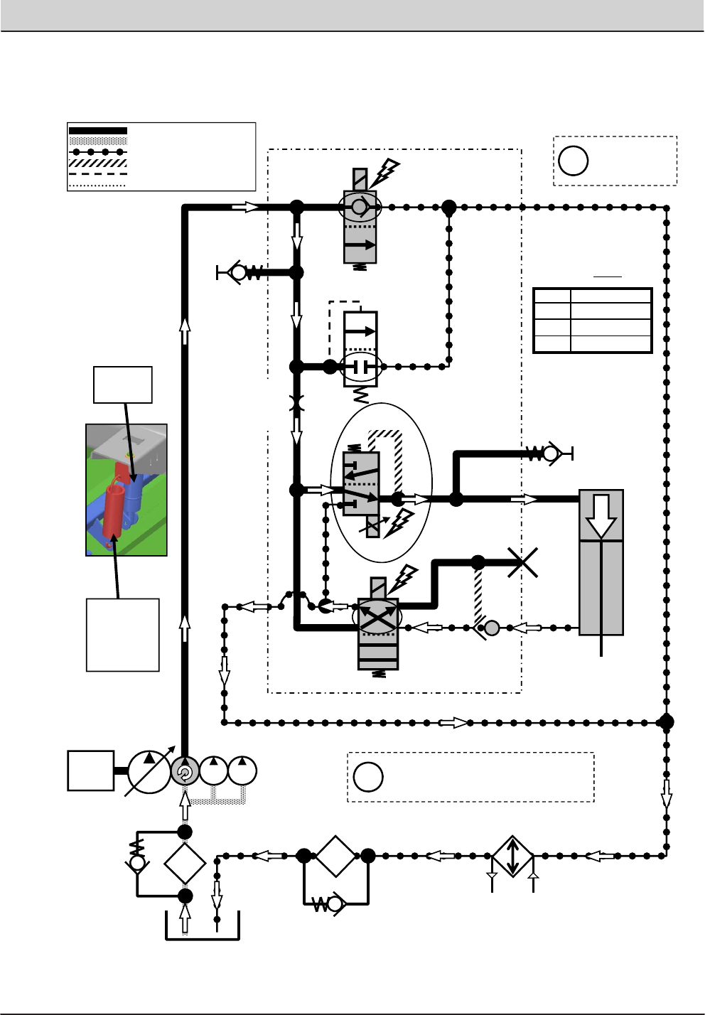
T20 Service Information (5-2017) 135
HYDRAULIC TROUBLESHOOTING
T20 Scrub Head Lower
Engine Speed: High RPM
SV7
G5
RV2
2500 PSI
(172.4 BAR)
SV2
SV3
LOWER
G2
G1
P2
T1
C2
C1
SCRUB HEAD
ACTUATOR
T2
ORIFICE
0.046 in
(1.17 mm)
SCREEN
SCRUB MANIFOLD
ENGINE
OIL
FILTER
35 PSI
(2.4 BAR)
OIL
COOLER
PC1
*PWM*
Pressure / Flow Line
Return or Low Pressure Line
Active Pilot Port Line
Inactive Pilot Port Line
Case Drain Line
Suction Line Gray items are
energized
or activated
Setting Pressure at G1
P1 44psi (3 bar)
P2 159psi (11 bar)
P3 240psi (16.5 bar)
Typical Default
Pressure Readings (+/- 15%)
Pressure settings P1, P2, & P3 are
the Touch Panel LED indicators
for Main Brush down pressure
Scrub
Head
Actuator
NOTE
SPRING
ASSIST
(Cylindrical
head ONLY)
i
i
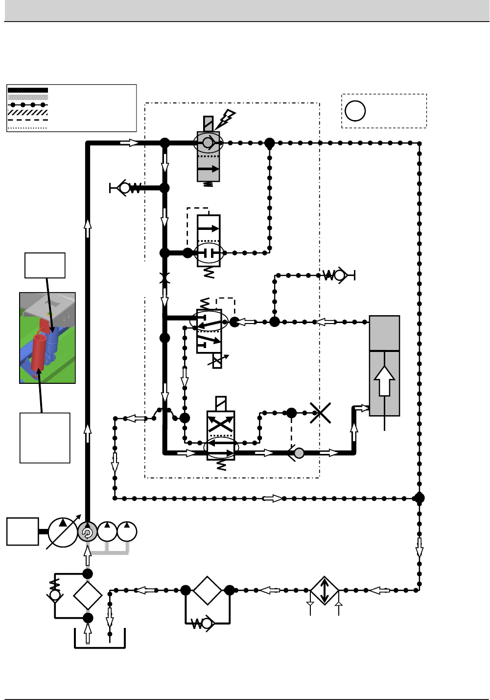
136 T20 Service Information (5-2017)
HYDRAULIC TROUBLESHOOTING
G2
T20 Scrub Head Lift
Engine Speed: High RPM
SV7
G5
SV3
LIFT
G2
G1
P2
T1
C2
C1
SCRUB HEAD
ACTUATOR
T2
SCREEN
SCRUB MANIFOLD
OIL
FILTER
OIL
COOLER
PC1
SV2
Pressure / Flow Line
Return or Low Pressure Line
Active Pilot Port Line
Inactive Pilot Port Line
Case Drain Line
Suction Line
ENGINE
Scrub
Head
Actuator
NOTE
SPRING
ASSIST
(Cylindrical
head ONLY)
RV2
2500 PSI
(172.4 BAR)
ORIFICE
0.046 in
(1.17 mm)
35 PSI
(2.4 BAR)
Gray items are
energized
or activated
i
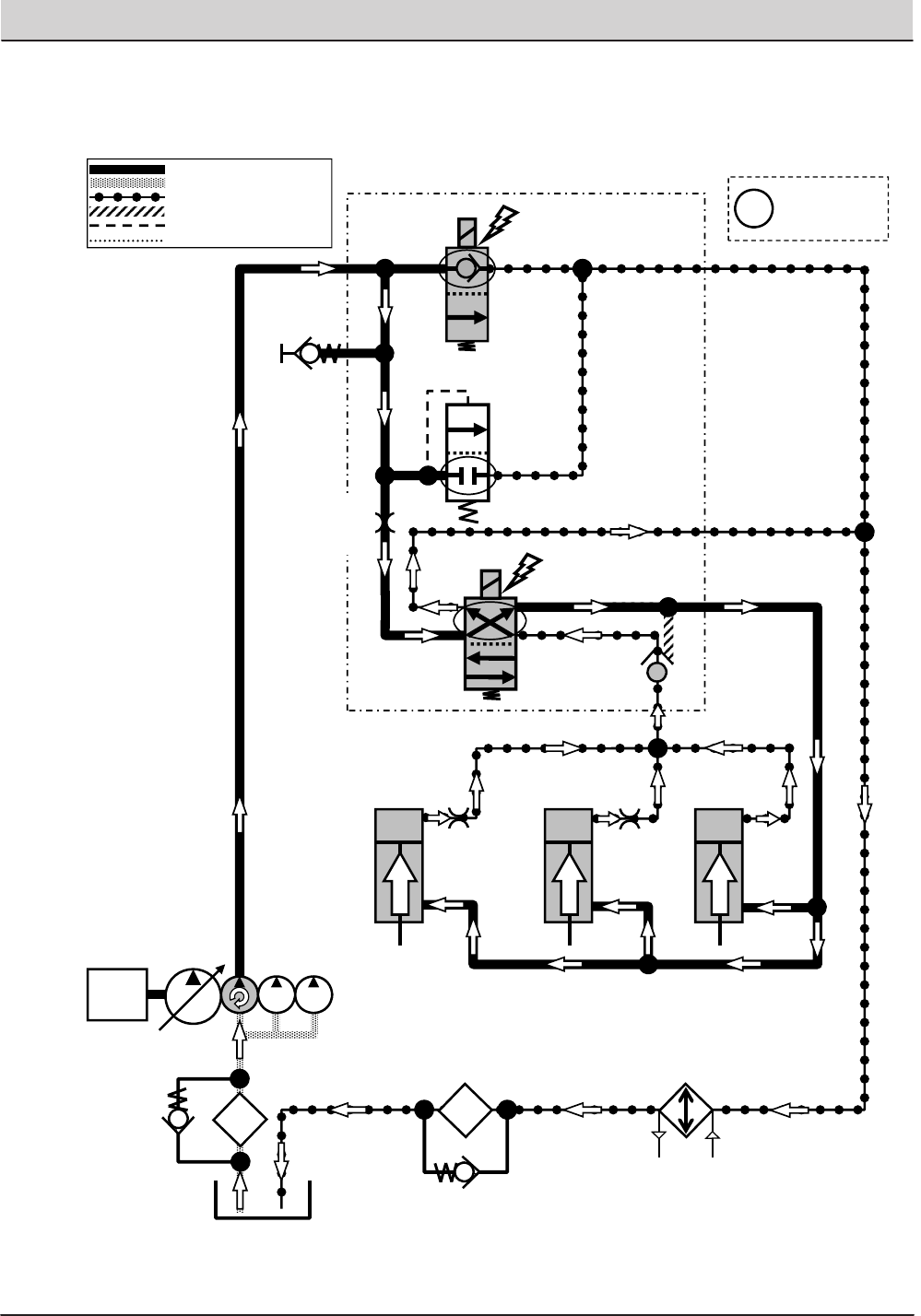
T20 Service Information (5-2017) 137
HYDRAULIC TROUBLESHOOTING
T20 Squeegees Lower
Engine Speed: High RPM
SV7
G5
P2
SV4
C4
T1
C2
LOWER
ORIFICE
0.031 in
(0.79 mm)
LEFT
SQUEEGEE
ACTUATOR
RIGHT
SQUEEGEE
ACTUATOR
REAR
SQUEEGEE
ACTUATOR
T2
SCREEN
SCRUB MANIFOLD
OIL
FILTER
OIL
COOLER
PC2
LOWER
LOWER
Pressure / Flow Line
Return or Low Pressure Line
Active Pilot Port Line
Inactive Pilot Port Line
Case Drain Line
Suction Line
ENGINE
RV2
2500 PSI
(172.4 BAR)
ORIFICE
0.046 in
(1.17 mm)
35 PSI
(2.4 BAR)
ORIFICE
0.031 in
(0.79 mm)
Gray items are
energized
or activated
i
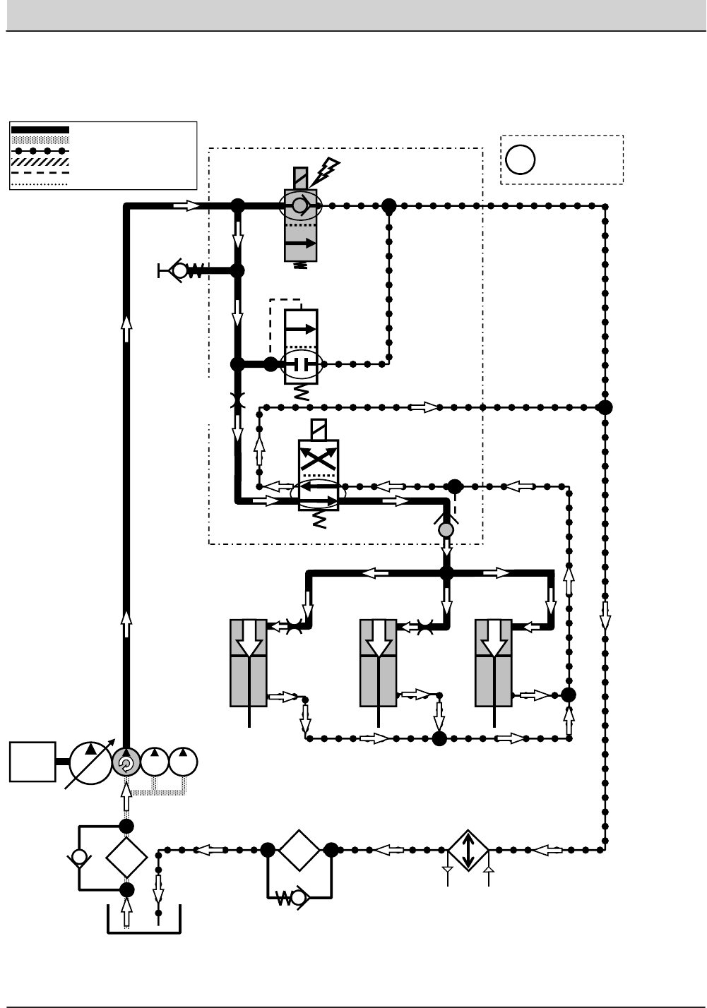
138 T20 Service Information (5-2017)
HYDRAULIC TROUBLESHOOTING
T20 Squeegees Lift
Engine Speed: High RPM
SV7
G5
OIL
COOLER
P2
SV4
C4
T1
C2
LIFT
LIFT
LIFT
LEFT
SQUEEGEE
ACTUATOR
RIGHT
SQUEEGEE
ACTUATOR
REAR
SQUEEGEE
ACTUATOR
T2
SCREEN
SCRUB MANIFOLD
OIL
FILTER
PC2
Pressure / Flow Line
Return or Low Pressure Line
Active Pilot Port Line
Inactive Pilot Port Line
Case Drain Line
Suction Line
ENGINE
RV2
2500 PSI
(172.4 BAR)
ORIFICE
0.046 in
(1.17 mm)
35 PSI
(2.4 BAR)
ORIFICE
0.031 in
(0.79 mm)
ORIFICE
0.031 in
(0.79 mm)
Gray items are
energized
or activated
i
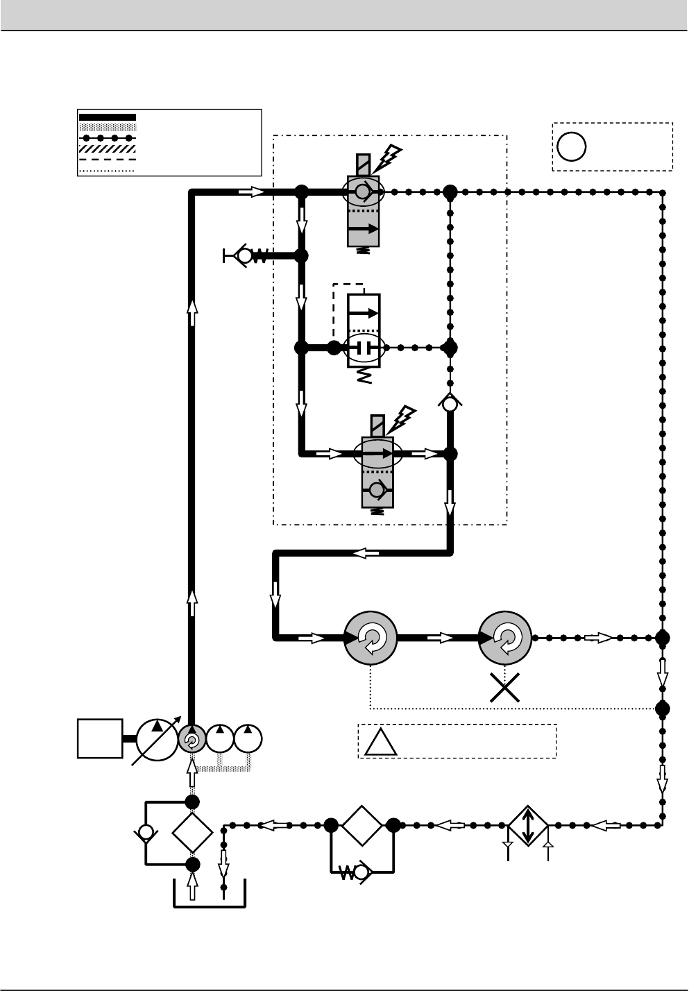
T20 Service Information (5-2017) 139
HYDRAULIC TROUBLESHOOTING
T20 Main Brushes ON (Cylindrical Only)
Engine Speed: High RPM
SV7
G5
OIL
COOLER
P2
SV6
M1
CV1
T2
SCREEN
SCRUB MANIFOLD
OIL
FILTER
Pressure / Flow Line
Return or Low Pressure Line
Active Pilot Port Line
Inactive Pilot Port Line
Case Drain Line
Suction Line
ENGINE i
Main Brush Motors speed:
400-480 RPM
REAR CYLINDRICAL
MAIN BRUSH MOTOR
FRONT CYLINDRICAL
MAIN BRUSH MOTOR
RV2
2500 PSI
(172.4 BAR)
35 PSI
(2.4 BAR)
Gray items are
energized
or activated
i
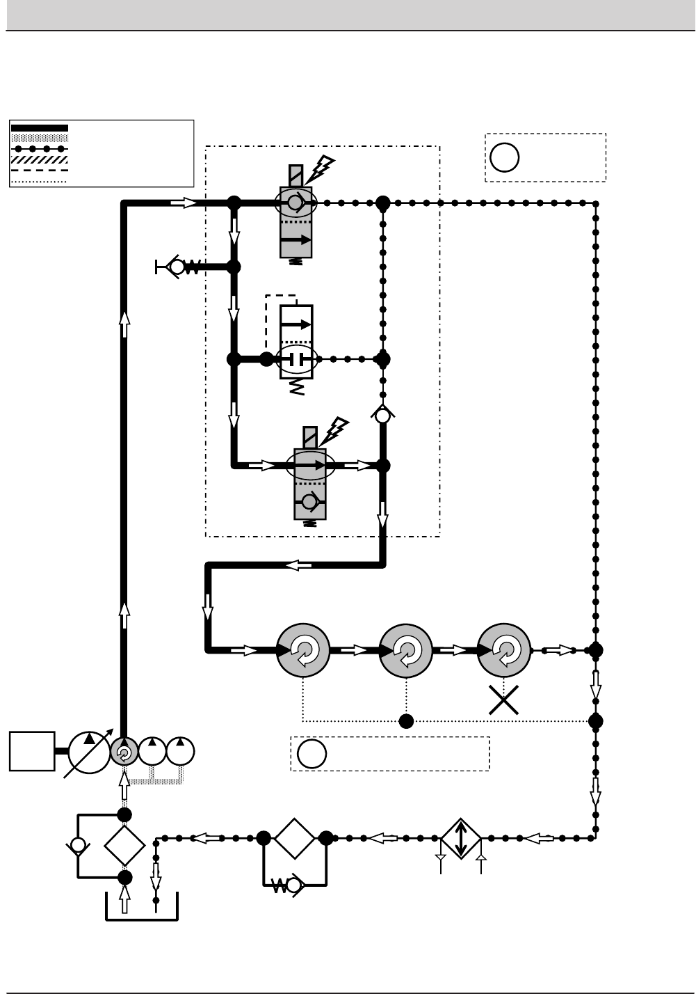
140 T20 Service Information (5-2017)
HYDRAULIC TROUBLESHOOTING
T20 Main Brushes ON (Disk Only)
Engine Speed: High RPM
SV7
G5
OIL
COOLER
P2
SV6
M1
CV1
T2
SCREEN
SCRUB MANIFOLD
LEFT DISK
MAIN BRUSH
MOTOR
RIGHT DISK
MAIN BRUSH
MOTOR
OIL
FILTER
Pressure / Flow Line
Return or Low Pressure Line
Active Pilot Port Line
Inactive Pilot Port Line
Case Drain Line
Suction Line
ENGINE Main Brush Motors speed:
230 RPM (+/- 10%)
CENTER DISK
MAIN BRUSH
MOTOR
RV2
2500 PSI
(172.4 BAR)
35 PSI
(2.4 BAR)
Gray items are
energized
or activated
i
i
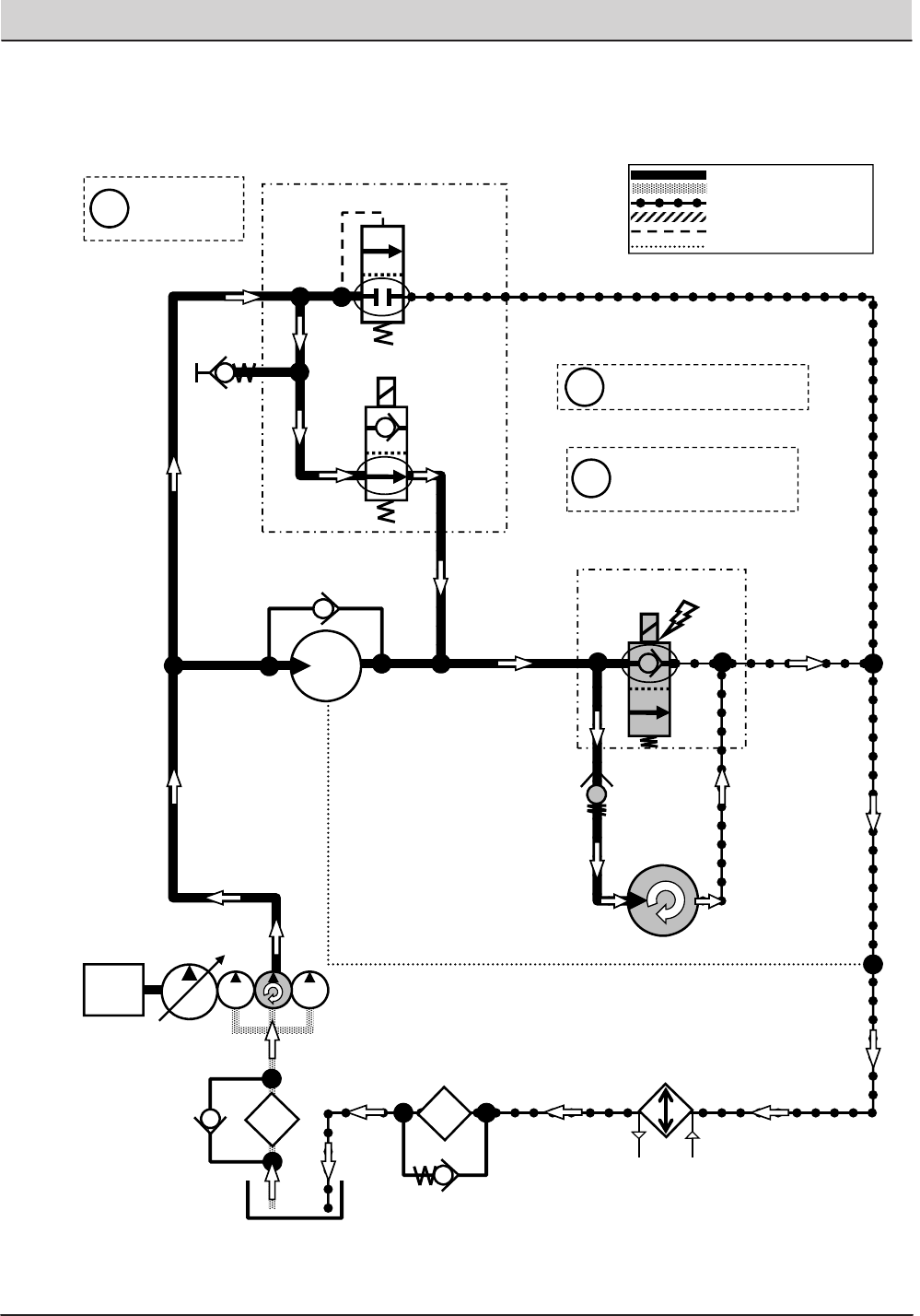
T20 Service Information (5-2017) 141
HYDRAULIC TROUBLESHOOTING
T20 Side Brush ON
Engine Speed: High RPM
SV1
G6
RV1
2500 PSI
(172.4 BAR)
OIL
COOLER
P1 T2
SCREEN
SCRUB MANIFOLD
25 PSI
(1.7 BAR)
SCRUB FAN
MOTOR
OIL
FILTER
SIDE BRUSH
MOTOR
SV8
SIDE BRUSH MANIFOLD
Pressure / Flow Line
Return or Low Pressure Line
Active Pilot Port Line
Inactive Pilot Port Line
Case Drain Line
Suction Line
ENGINE
Side Brush Motor speed:
140-160 RPM
M4
P3 T3
M2 T6
Side Brush can only be
operated when Main
Brushes are ON
35 PSI
(2.4 BAR)
Gray items are
energized
or activated
i
i
i
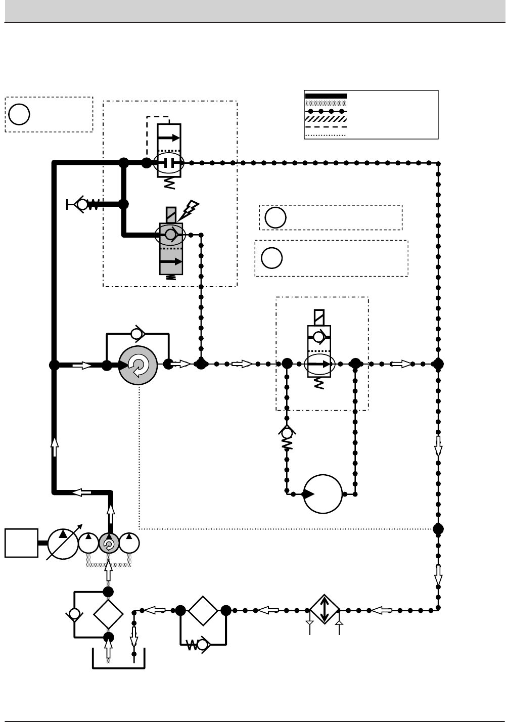
142 T20 Service Information (5-2017)
HYDRAULIC TROUBLESHOOTING
SCREEN
ENGINE
T20 Scrub Vacuum Fan ON
Engine Speed: High RPM
SV1
G6
OIL
COOLER
P1 T2
SCRUB MANIFOLD
SCRUB FAN
MOTOR
M4
P3
OIL
FILTER
Pressure / Flow Line
Return or Low Pressure Line
Active Pilot Port Line
Inactive Pilot Port Line
Case Drain Line
Suction Line
Scrub Fan Motor speed:
10,500 RPM (+/- 150 RPM)
Scrub Fan Motor vacuum:
34-39 in/H2O (86-99 cm/H2O)
measured at squeegee
SIDE BRUSH
MOTOR
SV8
SIDE BRUSH MANIFOLD
T3
M2 T6
25 PSI
(1.7 BAR)
35 PSI
(2.4 BAR)
RV1
2500 PSI
(172.4 BAR)
Gray items are
energized
or activated
i
i
i
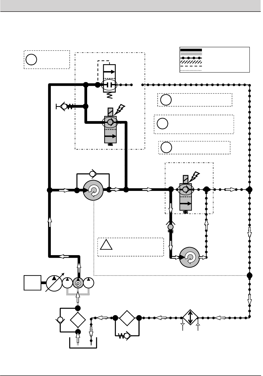
T20 Service Information (5-2017) 143
HYDRAULIC TROUBLESHOOTING
ENGINE
T20 Scrub Vacuum Fan & Side Brush ON
Engine Speed: High RPM
SV1
G6
OIL
COOLER
P1 T2
SCREEN
SCRUB MANIFOLD
SCRUB FAN
MOTOR
OIL
FILTER
Pressure / Flow Line
Return or Low Pressure Line
Active Pilot Port Line
Inactive Pilot Port Line
Case Drain Line
Suction Line
Side Brush Motor speed:
140-160 RPM
Scrub Fan Motor speed:
10,500 RPM (+/- 150 RPM)
Scrub Fan Motor vacuum:
34-39 in/H2O (86-99 cm/H2O)
measured at squeegee
i
Side Brush can only be
operated when Main
Brushes are ON
25 PSI
(1.7 BAR)
SIDE BRUSH
MOTOR
SV8
SIDE BRUSH MANIFOLD
P3 T3
M2 T6
35 PSI
(
2.4 BAR
)
RV1
2500 PSI
(172.4 BAR)
Gray items are
energized
or activated
i
i
i
i
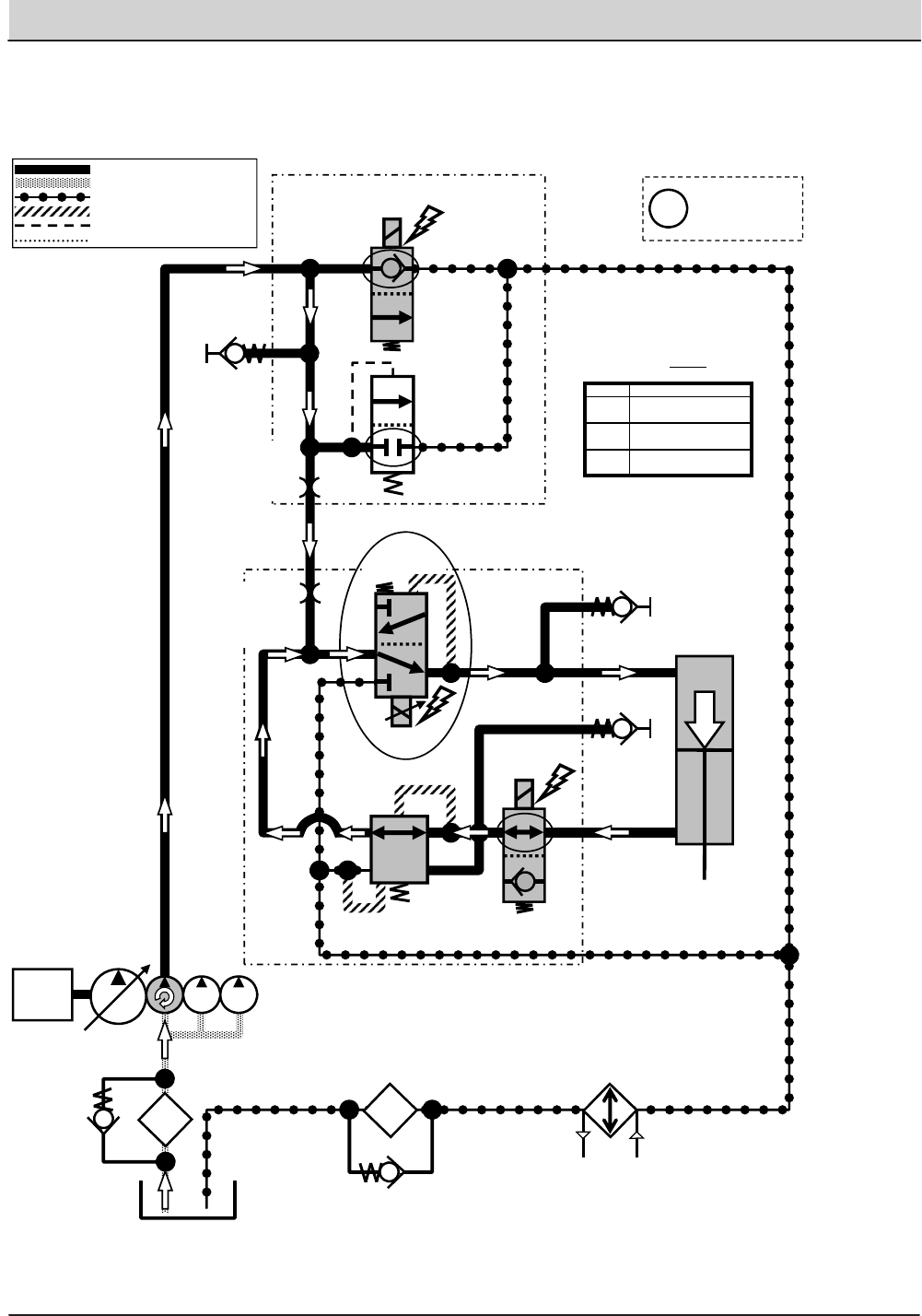
144 T20 Service Information (5-2017)
HYDRAULIC TROUBLESHOOTING
T20 Side Brush Lower
Engine Speed: High RPM
SV7
G5
P2
SIDE BRUSH
LIFT ACTUATOR
T2
SCREEN
SCRUB MANIFOLD
OIL
FILTER
OIL
COOLER
P7
P4
G13
LOWER
OR3
0.040 in
(1.02 mm)
SV10
SV11
PR1
400 PSI
(27.6 BAR)
G7
C6
C8
T4
*PWM*
SIDE BRUSH
MANIFOLD
Pressure / Flow Line
Return or Low Pressure Line
Active Pilot Port Line
Inactive Pilot Port Line
Case Drain Line
Suction Line
ENGINE
Setting Pressure at G13
P1 300 psi (20.7 bar)
P2 400 psi (27.6 bar)
P3 500 psi (34.5 bar)
Typical Default
Pressure Readings (+/- 15%)
RV2
2500 PSI
(172.4 BAR)
ORIFICE
0.055 in
(1.40 mm)
35 PSI
(2.4 BAR)
Gray items are
energized
or activated
i
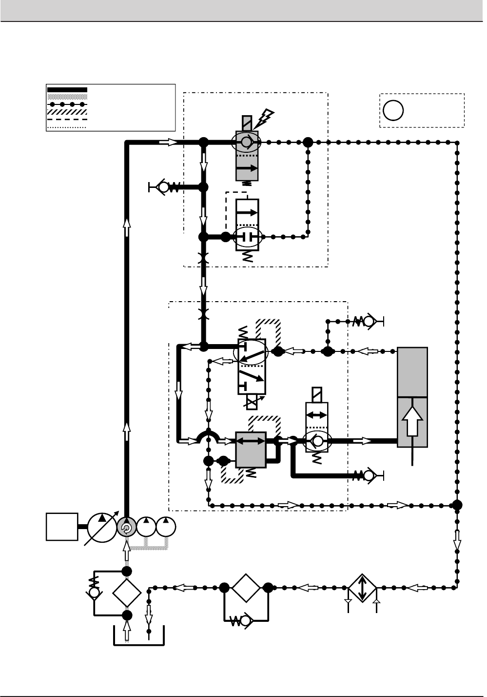
T20 Service Information (5-2017) 145
HYDRAULIC TROUBLESHOOTING
T20 Side Brush Lift
Engine Speed: High RPM
SV7
G5
P2
SIDE BRUSH
LIFT ACTUATOR
T2
SCREEN
SCRUB MANIFOLD
OIL
FILTER
OIL
COOLER
P7
P4
T4
SIDE BRUSH MANIFOLD G13
SV11
G7
LIFT
SV10
C6
C8
Pressure / Flow Line
Return or Low Pressure Line
Active Pilot Port Line
Inactive Pilot Port Line
Case Drain Line
Suction Line
ENGINE
OR3
0.040 in
(1.02 mm)
PR1
400 PSI
(27.6 BAR)
RV2
2500 PSI
(172.4 BAR)
ORIFICE
0.055 in
(1.40 mm)
35 PSI
(2.4 BAR)
Gray items are
energized
or activated
i
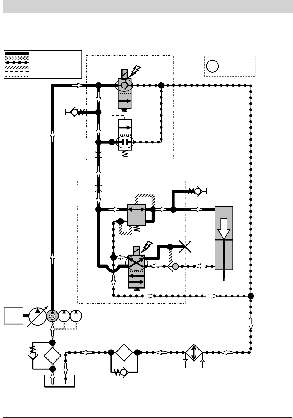
146 T20 Service Information (5-2017)
HYDRAULIC TROUBLESHOOTING
T20 Side Brush Extend
Engine Speed: High RPM
SV7
G5
P2
SIDE BRUSH
EXTEND ACTUATOR
T2
SCREEN
SCRUB MANIFOLD
OIL
FILTER
OIL
COOLER
P7
P4
SIDE BRUSH MANIFOLD G7
EXTEND
C7
C5
T4
SV12
PC8
G10
Pressure / Flow Line
Return or Low Pressure Line
Active Pilot Port Line
Inactive Pilot Port Line
Case Drain Line
Suction Line
ENGINE
OR3
0.040 in
(1.02 mm)
PR1
400 PSI
(27.6 BAR)
RV2
2500 PSI
(172.4 BAR)
ORIFICE
0.055 in
(1.40 mm)
35 PSI
(2.4 BAR)
Gray items are
energized
or activated
i
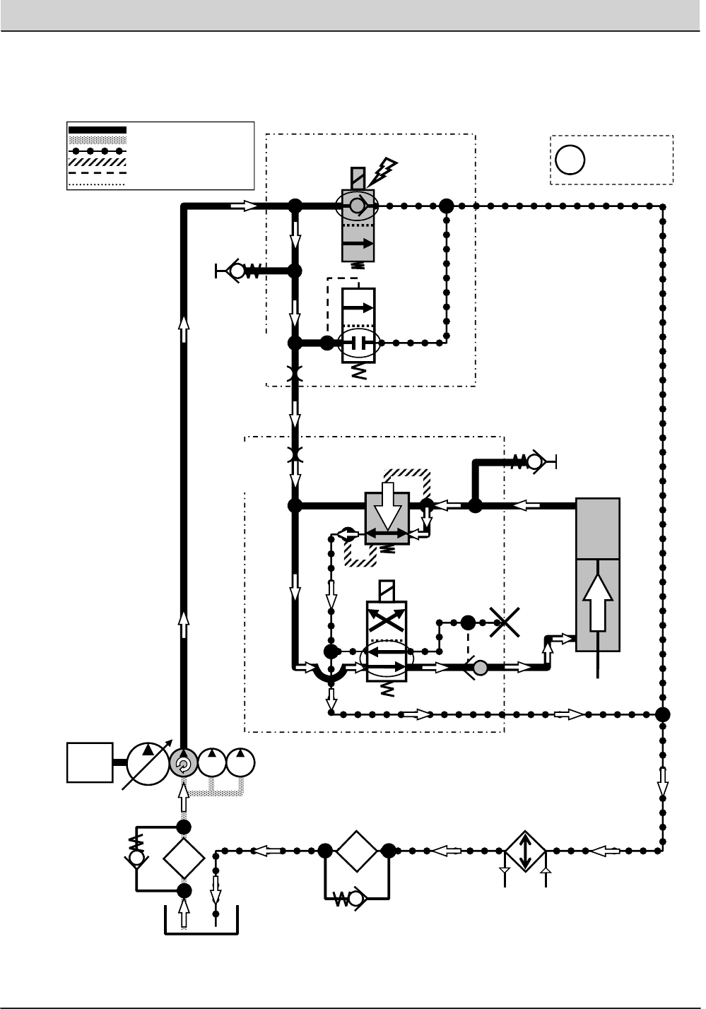
T20 Service Information (5-2017) 147
HYDRAULIC TROUBLESHOOTING
T20 Side Brush Retract
Engine Speed: High RPM
SV7
G5
P2
SIDE BRUSH
EXTEND ACTUATOR
T2
SCREEN
SCRUB MANIFOLD
OIL
FILTER
OIL
COOLER
P7
P4
SIDE BRUSH MANIFOLD G7
C7
C5
T4
SV12
PC8
G10
RETRACT
Pressure / Flow Line
Return or Low Pressure Line
Active Pilot Port Line
Inactive Pilot Port Line
Case Drain Line
Suction Line
ENGINE
OR3
0.040 in
(1.02 mm)
PR1
400 PSI
(27.6 BAR)
RV2
2500 PSI
(172.4 BAR)
ORIFICE
0.055 in
(1.40 mm)
35 PSI
(2.4 BAR)
Gray items are
energized
or activated
i
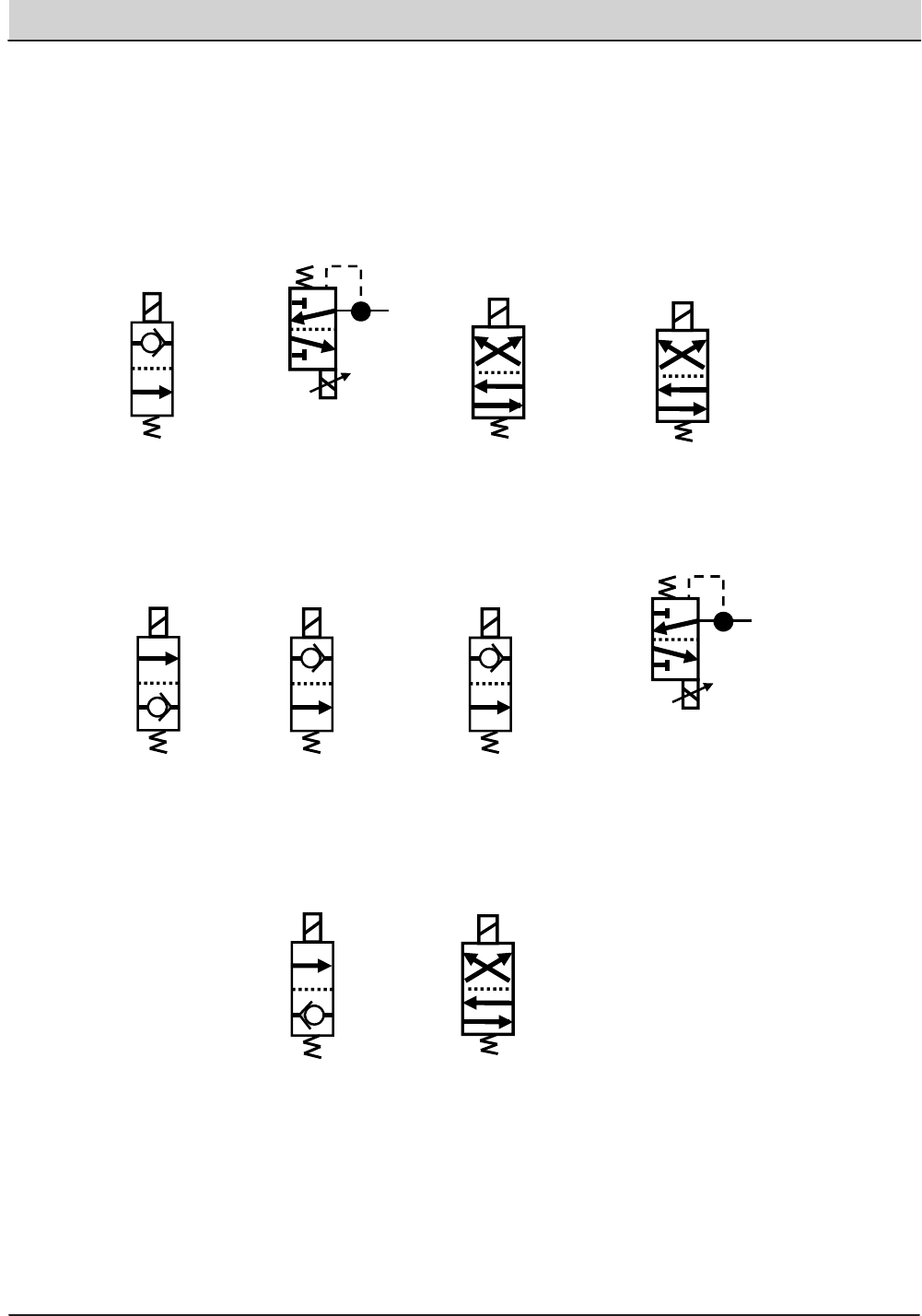
148 T20 Service Information (5-2017)
HYDRAULIC TROUBLESHOOTING
T20 Hydraulic Solenoid Valve Details
SV1
SV2
*PWM*
SV3 SV4
SV6 SV7 SV8
SV10
*PWM*
SV11 SV12

T20 Service Information (5-2017) 149
SERVICE
SERVICE
PROPANEL SERVICE MODES
SERVICE MODE
The Service Modes are designed for Service Tech-
nician use only. A qualified Service Technician can
interface with the machine to configure the machine
and to test specific components.
1. Key switch on. With the machine display powered
on, press the ‘Question Mark’ Icon.
2. Press the Login Icon and enter the Service
Mode Login number and press the enter icon.
(083957530)
3. Press the ‘Gears’ icon.
4. Using the down arrow, scroll to the bottom of the
listed functions.
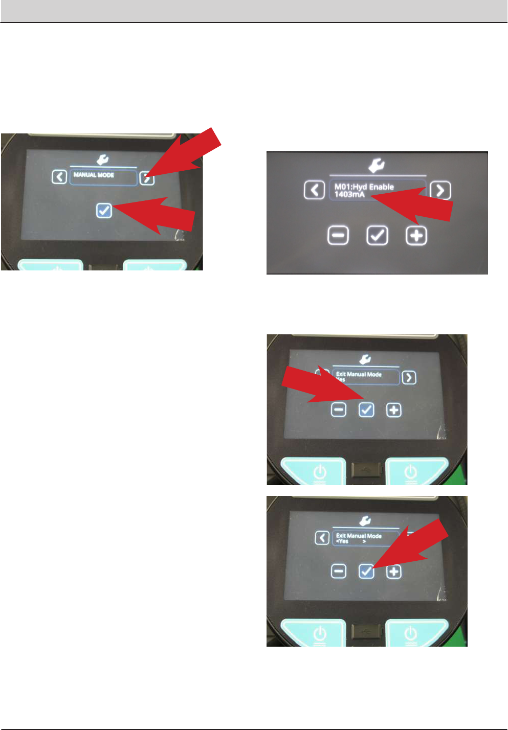
150 T20 Service Information (5-2017)
SERVICE
MANUAL MODE
1. Enter the Service Mode (See SERVICE MODE)
and press the right arrow to scroll to the
MANUAL MODE screen.
2. To enter the Manual Mode, press the ‘Check
Mark’ icon.
3. Manual Mode allows viewing many component
amperage draws or RPM. This includes:
• M01: Hyd Enable = Hydraulic Enable
• M02: MB Down Act = Main Brush Dwn Actuator
• M03: MB ON Motor = Main Brush Motor ON
• M04: MB DP PWM = Main Brush Down Pressure
• M05: MB WaterVlv - Main Brush Water Valve
• M06: SB Ext. Act = Side Brush Extend Actuator
• M07: SB Down Act = Side Brush Down Actuator
• M08: SB ON Motor = Side Brush Motor ON
• M09: SB DP PWM = Side Brush Down Pressure
• M10: SB WaterVlv = Side Brush Water Valve
• M11: Water Vac = Water Vacuum
• M12: Dust Vac = Dust Vacuum
• M13: Squeegee Act = Squeegee Actuator
• M14: Hopper Valve1 -= Hopper Valve 1
• M14: Hopper Valve2 = Hopper Valve 2
• M15: Hp Latch = Hopper Latch
• M16: Hp Door = Hopper Door
• M17: Shaker - Shaker
• M18: Reverse = Reverse Sensor
• M19: Shutdown = Shutdown Relay
• M20: Alarm = Alarm
• M21: Horn = Horn
• M22: Det Pump = Detergent Pump
• M23: Alt Pump = Alternate Pump
• M24: AltHighFlow = Alternate High Flow
• M25: AltSideBrush = Alternate Side Brush
• M26: Sol AutoFill = Solution Auto Fill
• M27: Rec AutoFill = Recovery Auto Fill
• M28: Engine Speed = Engine RPM
Note: If a component is not installed on the machine,
the message ‘Not Installed’ is displayed.
4. To activate a component, press the check mark.
To deactivate a component, press the check
mark again.
Note: When a component is active, the amperage
output to that component or the RPM of that
component is displayed.
5. To exit Manual Mode, use the right arrow to scroll
to the Exit Manual Mode screen and press the
‘Check Mark’ icon twice.
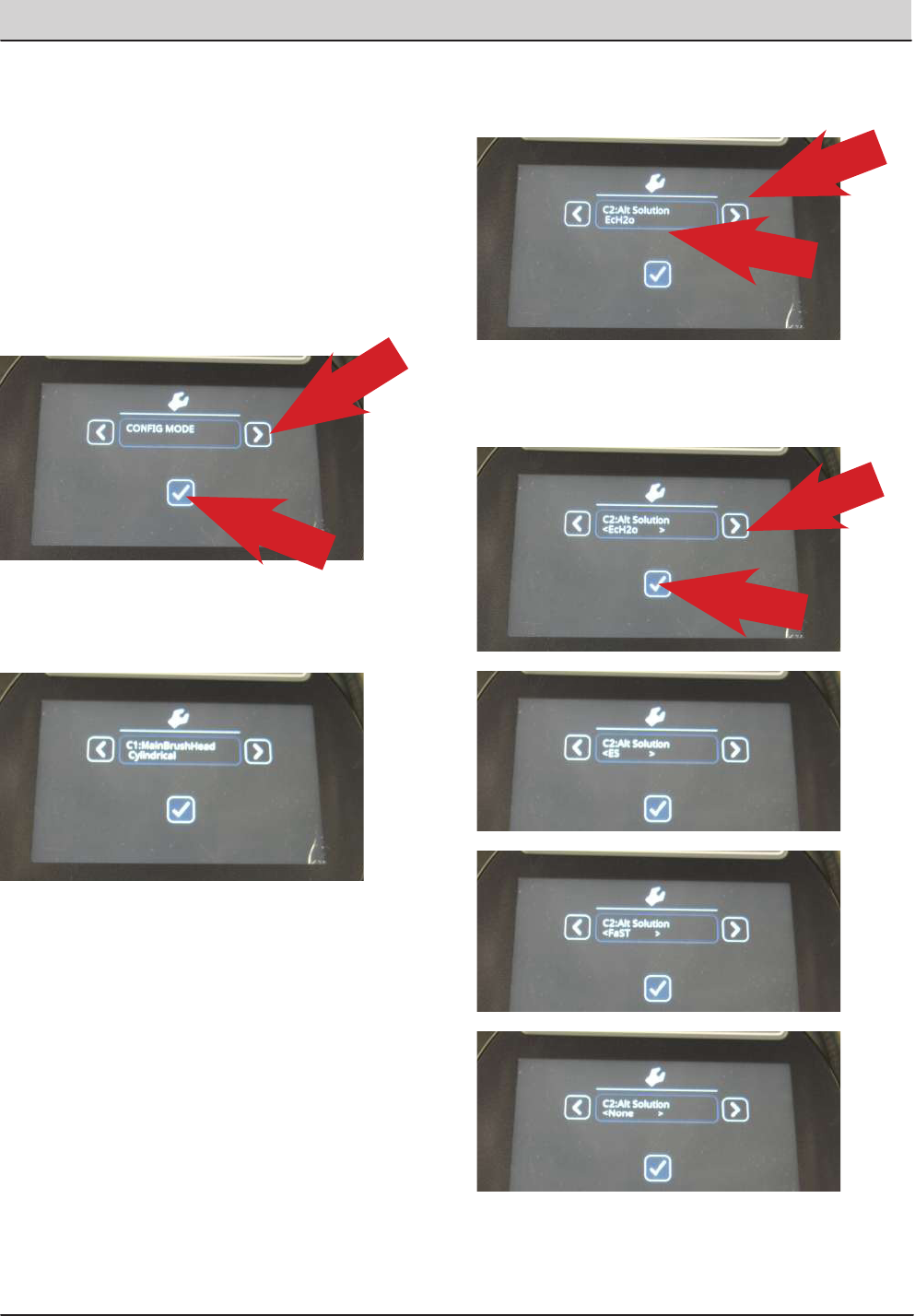
T20 Service Information (5-2017) 151
SERVICE
CONFIGURATION MODE
Configuration Mode is an onboard diagnostic utility
that configures controller software to operate optional
equipment and to electronically adjust certain output
functions.
1. Enter the Service Mode (See SERVICE MODE)
and press the right arrow to scroll to the CONFIG
MODE screen.
2. To enter the CONFIG MODE, press the ‘Check
Mark’ icon.
3. The C1: MainBrushHead choice feature is used
on the T20 machines. You can choose Disk or
Cylindrical Head Type.
4. Press the right arrow to scroll to the next
conguration option and the ‘Check Mark’ icon to
change settings.
5. Continuously press the right arrow to scroll to
the desired conguration option and press the
‘Check Mark’ icon to choose a setting.
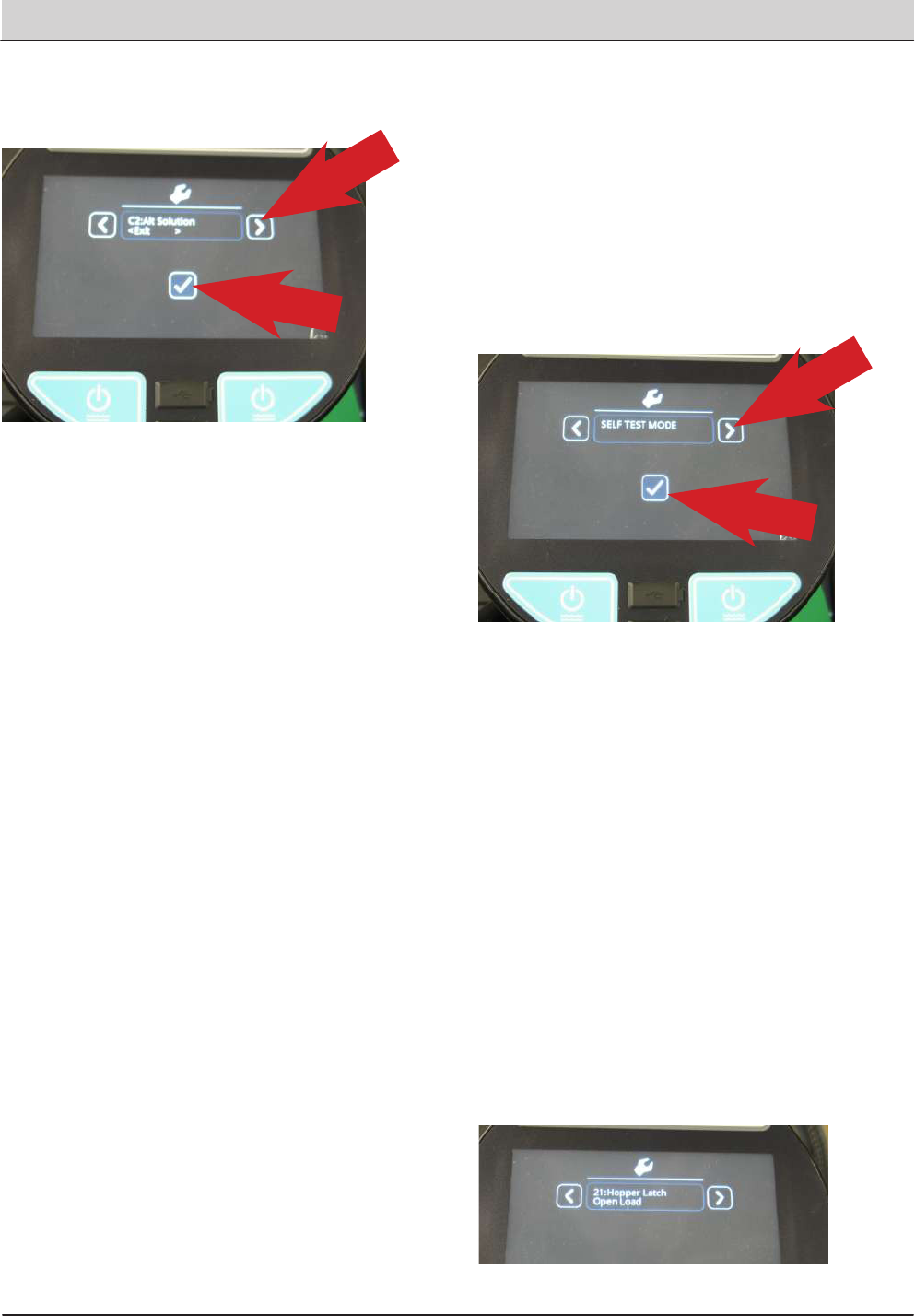
152 T20 Service Information (5-2017)
SERVICE
6. If no change is required, press the right arrow
until you see the ‘Exit’ option and press the
‘Check Mark’ icon twice, to exit.
7. Follow the same procedure for other optional
equipment and water ow rate setup.
Including:
• C1: Main Brush Head
• C2: Alt Solution
• C5: Side Brush
• C6: Seat Switch
• C7: Water Level
• C8: IRIS Module
• C9: Run-In Mode
• C10: Neut. Scrub
Additional Water Level Setting Information:
There are three water level range setting options.
• Economy
• Normal
• Heavy
When a settings is chosen, the operator can adjust three
ow rate settings within that range.
SELF TEST MODE
Self Test Mode is an onboard diagnostic utility
that tests for open or shorted output circuits. Once
completed, open and/or shorted output faults, are
displayed.
1. Enter the Service Mode (See SERVICE MODE)
and press the right arrow to scroll to the SELF
TEST MODE screen.
2. To enter the SELF TEST MODE, press the
‘Check Mark’ icon.
3. The self test will automatically begin.
CAUTION: Many of the machine functions
will automatically turn on. Stay clear of
the machine during the self test.
These are a few examples of the tests performed
during the Self Test process. The table on the next
page shows all of the test names and descriptions.
• Test Hydraulic Enable Valve
• Test Main Brush Down Actuator
• Test Main Brush Motor
• Test Main Brush PWM Valve
• Test Alternate Solution Pump
Some of the tests listed will only be performed if the
machine has that specific option and it is configured
correctly.
4. When the self test is completed, faults found will
be displayed as an open or shorted load.
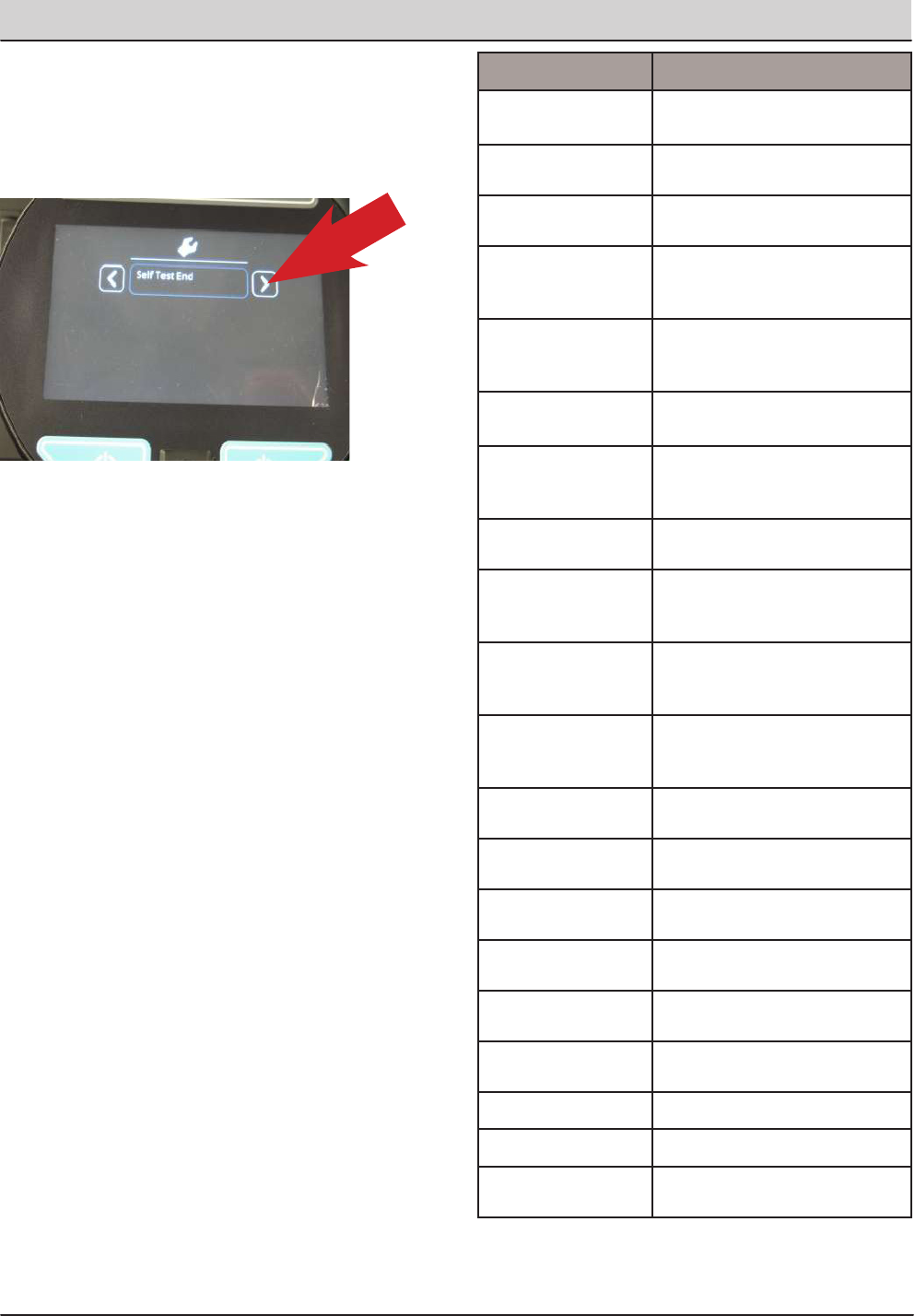
T20 Service Information (5-2017) 153
SERVICE
5. If faults exist, continually press the right arrow
icon to display all faults found.
If there are no other faults found or no faults found
initially, ‘Self Test End’ is displayed. Pressing the
right arrow again will display any faults found again.
All successful tests performed will result in the mes-
sage ‘Done’. This indicates that test passed.
If a fault is found during the ‘Self Test’ , either ‘Open’
or ‘Short’ will be displayed for that test.
“Open” (Indicates current could not be delivered to
that circuit)
“Short” (The current draw is over the threshold, indi-
cating a short circuit)
Follow the diagnostic steps in this manual for diag-
nosing an open or shorted circuit.
To exit the self test mode, turn off the machine key.
The machine will return to normal operational mode
when the key switch is turned on again.
Self Test Name: Test Description:
1:Enable Hydraulic
Valve
Test the valve which enables
machine hydraulics.
2:MBrush Down Tests the valve which controls
‘Main Brush Down’ actuation.
3:MBrush Motor Tests the valve which controls
the Main Brush motor
4:MBrush PWM
Valve
Tests PWMed control of the
Main Brush Down valve (for
down pressure control).
5:MBrush Water
Valve
Tests the valve which controls
solution delivery to the Main
Brush.
6:SBrush Down
Actuator
Tests the valve which controls
‘Side Brush Down’ actuation.
7:SBrush Ext Ac-
tuator
Tests the valve which controls
‘Side brush Extension’ actua-
tion.
8:SBrush Motor Test the valve which controls
the Side Brush motor.
9:SBrush PWM
Valve
Tests PWMed control of the
Side Brush Down valve (for
down pressure control).
10:SBrush Water
Valve
Tests the valve which controls
solution delivery to the Side
Brush
11:Scrub Vac Fan Tests the vacuum fan for the
scrub subsystem (‘water pickup
fan).
12:Sweep Vac Fan Tests the vacuum fan for the
sweep subsystem.
13: Squeegee Act Tests the valve which controls
the Squeegee Actuator.
14: SolTnk AF Tests the Autoll valve for the
Solution Tank. (If Equipped)
15:RecTnk AF Tests the Autoll valve for the
Recovery Tank. (If Equipped)
16:ReverseRelay Tests the relay for reverse driv-
ing.
17:ShakerRelay Tests the relay for the lter
shaker.
18:Horn Horn test.
19:Alarm Backup alarm test.
28: ShudownRelay Tests the emergency engine
shutdown relay.
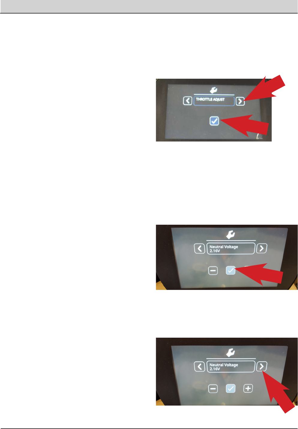
154 T20 Service Information (5-2017)
SERVICE
INPUT DISPLAY MODE
Input Display Mode is an onboard diagnostic utility
that displays controller input conditions. Input Display
Mode displays text messages for hard-wired switch,
sensor, and touch panel button inputs.
6. Enter the Service Mode (See SERVICE MODE)
and press the right arrow to scroll to the INPUT
DISPLAY MODE screen.
7. To enter the INPUT DISPLAY MODE, press the
‘Checkmark’ icon.
8. The display will indicate the switch or sensor
being tested. When the position of the switch or
the state of the sensor is changed, the results of
that change is displayed.
The components that can be tested with Input
Display Mode Include:
• I1: SolTnk Empty
• I2: SolTnk Full
• I3: RecTnk Full
• I4: RedTank 1/2Full
• I5: Clogged HpFlt
• I6: CloggedHydFlt
• I7: ThermalSentry Hopper Fire
• I8: Seat Switch
• I9: Brake Switch
• I10: HighEngTemp
• I11: Low Oil Psr
• I12: Check Engine
• I13: EcH2o Green
• I14: EcH2o Red
• I15: Hp Position
• I16: FilterShaker
• I17: Hp Up Rocker
• I18: HPDownRocker
• I19: HpDoor Open
• I20: HPDoor Close
• I21: Alternator
• I22: Throttle
• I23: Fuel Sender
• I24: Hyd Temp
THROTTLE ADJUST MODE
1. Enter the Service Mode (See SERVICE MODE)
and press the right arrow to scroll to the
THROTTLE ADJUST MODE screen.
2. To enter the THROTTLE ADJUST MODE, press
the ‘Check Mark’ icon.
3. The actual ‘Neutral Voltage’ value of the throttle
position sensor is displayed. Pressing the ‘Check
Mark’ sets the Forward and Reverse sense
voltage values, based on this Neutral Voltage
value.
The machine operation should be tested to confirm
the rear squeegee raises and lowers at the proper
times when the machine is propelled forward and
backward.
4. If the rear squeegee raises and lowers too soon
or too late, you will need to adjust the Reverse
voltage value and/or the Forward voltage value.
Press the right arrow to proceed to the Forward
Threshold voltage value.
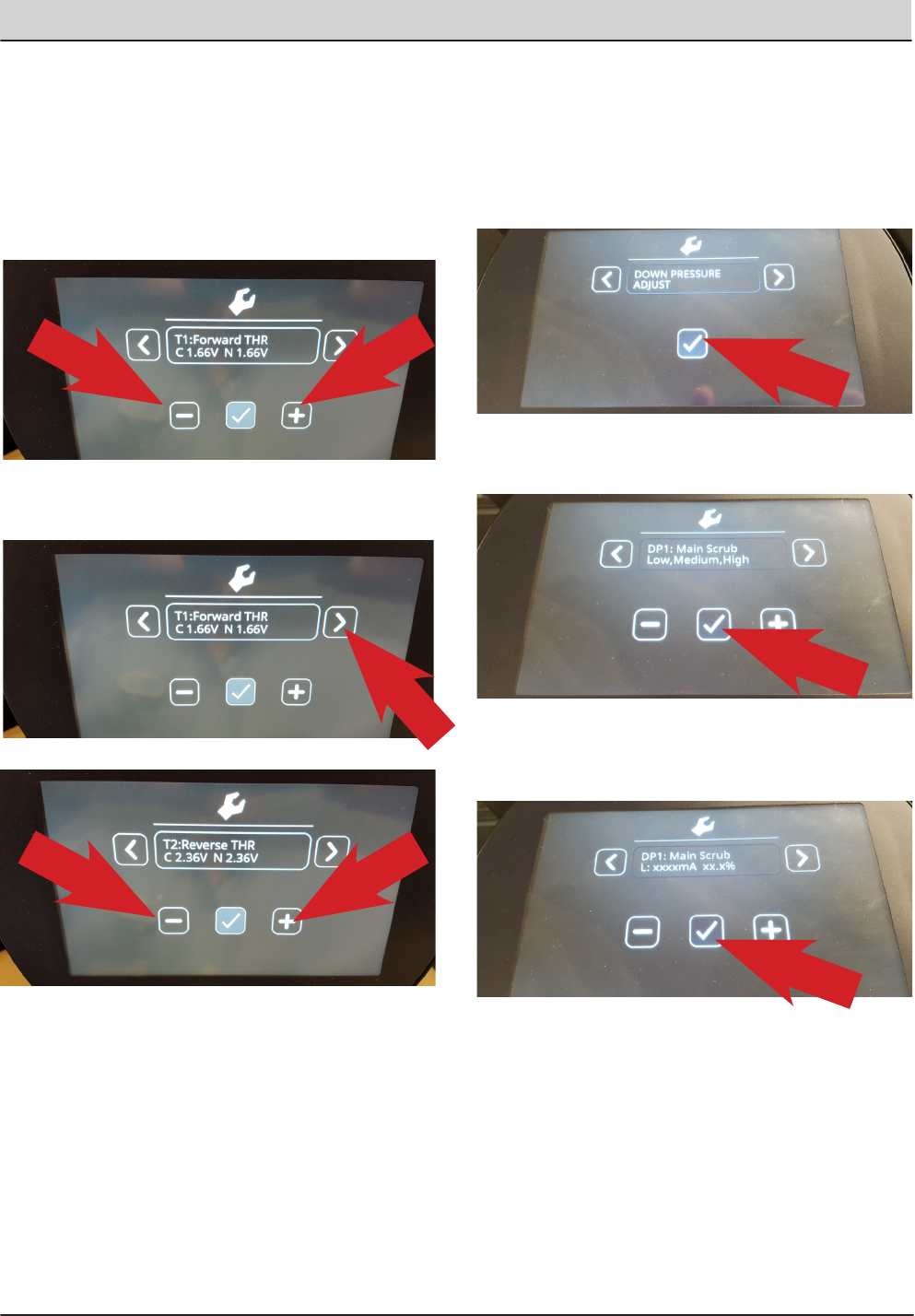
T20 Service Information (5-2017) 155
SERVICE
Note: the ‘C’ indicates the Current voltage value
and the ‘N’ indicates the New voltage value you are
setting. Press the ‘minus’ icon to reduce the N (New)
value and the ‘Positive’ icon to increase the N value.
The higher the value (a value closer to the Neutral
Voltage value), the quicker the system will react to
forward direction movement. Press the ‘Check Mark’
to make your ‘N’ New value the ‘C’ Current value.
5. Press the right arrow to proceed to the Reverse
Threshold voltage value.
6. If the Reverse Threshold requires adjustment
press either the ‘minus’ icon to reduce the N
voltage or the ‘plus’ icon to increase the N
voltage. The lower the value (a value closer
to the Neutral Voltage value), the quicker the
system will react to reverse direction movement.
Once the desired setting is achieved, press the
‘Check Mark’ to accept the change and confirm
proper machine operation. Scroll to Exit and press
the ‘Check Mark’ twice.
DOWN PRESSURE ADJUST MODE
1. Enter the Service Mode (See SERVICE MODE)
and press the right arrow to scroll to the DOWN
PRESSURE ADJUST MODE screen.
2. To enter the DOWN PRESSURE ADJUST MODE, press
the ‘Check Mark’ icon.
3. To enter the DOWN PRESSURE ADJUST MODE for the
Main Scrub Brushes, press the ‘Check Mark’ icon.
4. To enter the ‘L’ (Low Down Pressure Setting Mode)
for the Main Scrub Brushes, press the ‘Check Mark’
icon.
5. To increase the Low Setting Down Pressure for
the Main Scrub Brushes, press the ‘Plus’ icon to
increase the mA setting for the control valve. To
decrease the pressure, press the ‘Minus’ icon to
decrease the mA setting for the control valve.
Each time an icon is pressed, the electrical
signal to the solenoid is changed. This electrical
signal is measured in mA (milliamperes).

156 T20 Service Information (5-2017)
SERVICE
6. Press the ‘Check Mark’ icon to move backwards, then
the ‘Right Arrow’ to move to the M: (Medium Down
Pressure Setting) then press the ‘Check Mark’ to
allow you to set the Medium down pressure setting,
if desired.
7. Press the ‘Check Mark’ icon to move backwards,
then the ‘Right Arrow’ to move to the H: (High Down
Pressure Setting) then press the ‘Check Mark’ to
allow you to set the High down pressure setting, if
desired.
8. Press the ‘Check Mark’ icon to move backwards, then
the ‘Right Arrow’ to move to move to Main Scrub
Exit.
9. Press the ‘Check Mark’ icon to Exit the Main Scrub
Down Pressure Setting Mode.
10. Press the ‘Right Arrow’ icon to move to the Side
Scrub Brush Down Pressure Adjust Mode. Follow
the same process as above to make adjustments
to the Side Scrub Brush Down pressure, if
desired.
NOTE: Refer to the ‘Default Down Pressure List’ below, for
the factory default down pressure settings.
DEFAULT DOWN PRESSURE LIST
Note: There is a low limit of 100mA and a high limit of
950mA for each brush pressure setting.
Main Scrub Brushes:
• Disk Low Pressure Default Setting, 358mA.
• Disk Medium Pressure Default Setting, 458mA.
• Disk High Pressure Default Setting, 548mA.
• Cyl. Low Pressure Default Setting, 340mA.
• Cyl. Medium Pressure Default Setting, 440mA.
• Cyl. High Pressure Default Setting, 530mA.
Side Scrub Brush:
• Low Pressure Default Setting, 600mA.
• Medium Pressure Default Setting, 675mA.
• High Pressure Default Setting, 730mA.
11. To exit the Down Pressure Adjust Modes, press
the Right Arrow until you see Exit DP Adjust.
Press the ‘Check Mark’ two times to exit this
mode.
12. To exit the Service Modes, turn o the key switch
and then turn it on again.
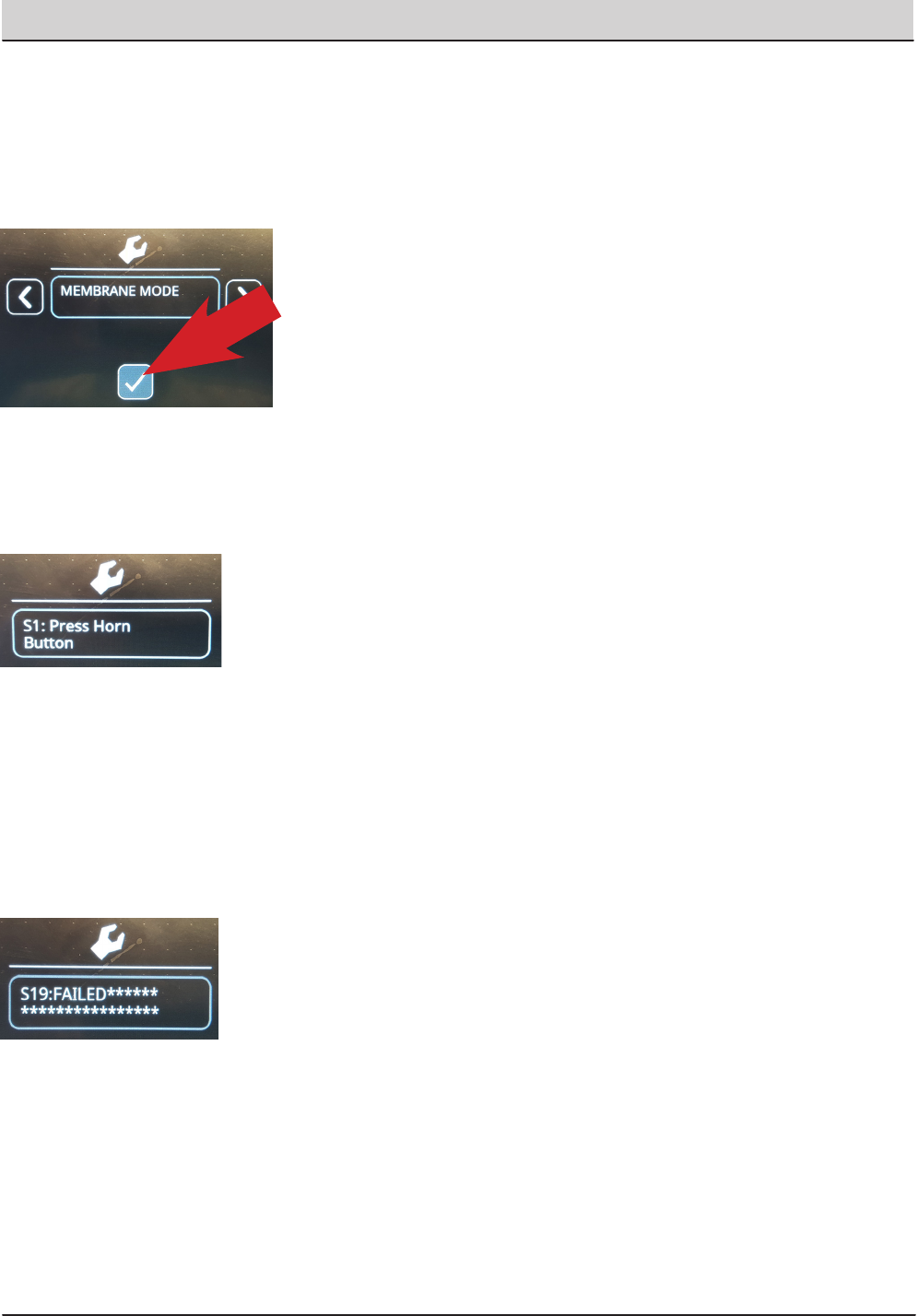
T20 Service Information (5-2017) 157
SERVICE
MEMBRANE TEST MODE
1. Enter the Service Mode (See SERVICE MODE)
and press the right arrow to scroll to the
MEMBRANE TEST MODE screen.
2. To enter the MEMBRANE TEST MODE, press
the ‘Check Mark’ icon.
3. The MEMBRANE TEST MODE allows you to test
the touch button functions, on the control panel.
When you are in the Membrane Test Mode, you
are directed to press each Membrane Button to
test it’s functionality.
4. When you press a button as directed, if the
button functions properly, you will be directed to
press another button.
Note: If you delay pressing the requested button too
long, you may see a ‘FAILED’ message displayed. If
this happens, restart the testing procedures.
If a button fails to function as designed, you will re-
ceive the message ‘FAILED’ in the display window.
5. To exit the Service Modes, turn off the key switch
and then turn it on again.
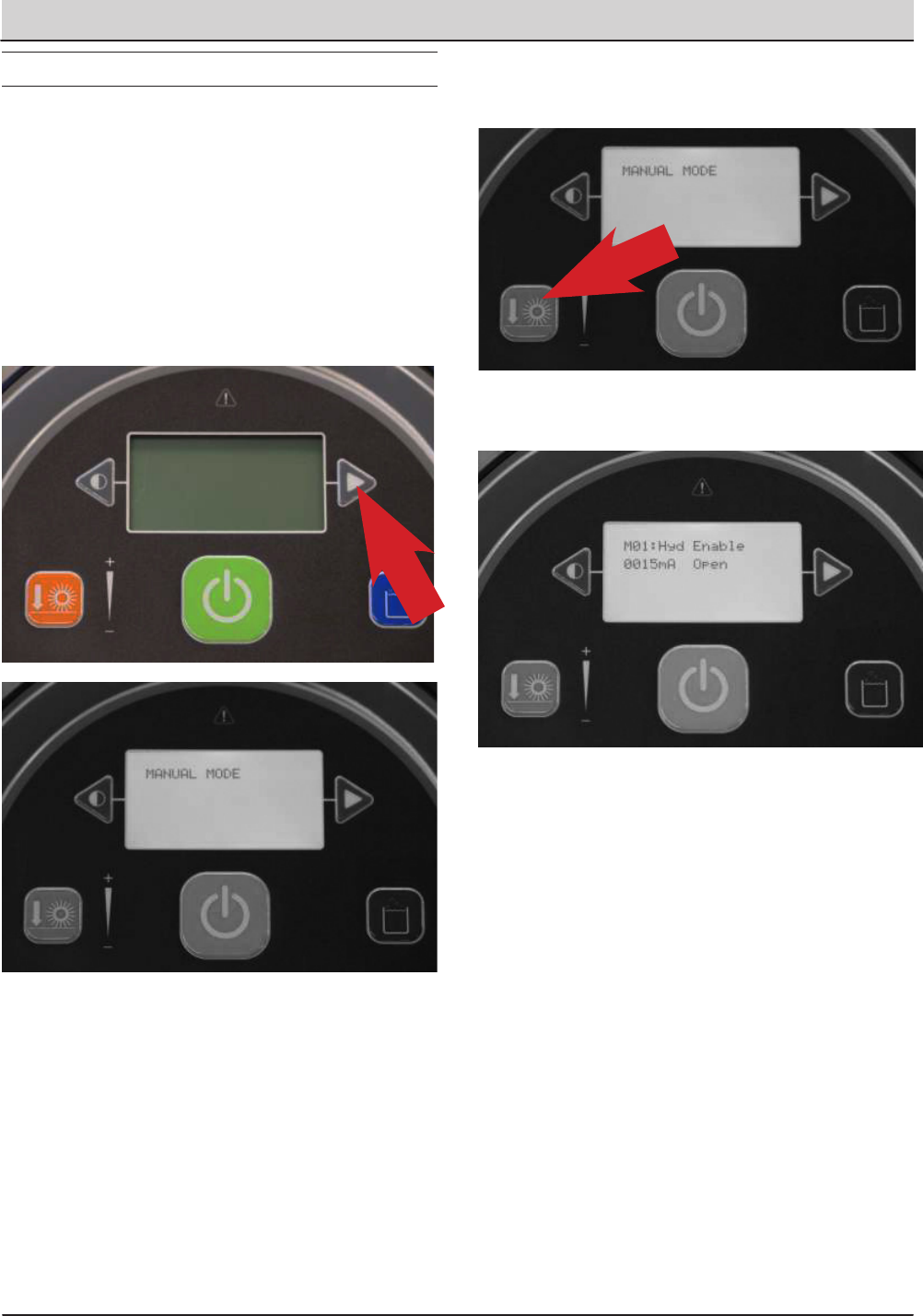
158 T20 Service Information (5-2017)
SERVICE
MEMBRANE PANEL SERVICE MODES
SERVICE MODE
The Service Modes are designed for Service Tech-
nician use only. A qualified Service Technician can
interface with the machine to configure the machine
and to test specific components.
1. Hold the Right Arrow next to the display down
and turn the key switch on. Continue to hold the
Right Arrow down until you see the message
‘Manual Mode’.
2. You can continue to press the right arrow
until you see the mode you want to enter. The
available modes are:
• Manual Mode
• Congure Mode
• Self Test Mode
• Input Display
• Throttle Adjust
• Down Pressure Adjust
• Membrane Test
3. When you see the mode you want to enter, press
the Orange Down Pressure Button to enter that
mode.
Note: The image below is the rst message
displayed when you enter the Manual Mode.
4. After the key switch is turned o, the machine will
return to ‘Normal Mode’ when the key is turned on
again.
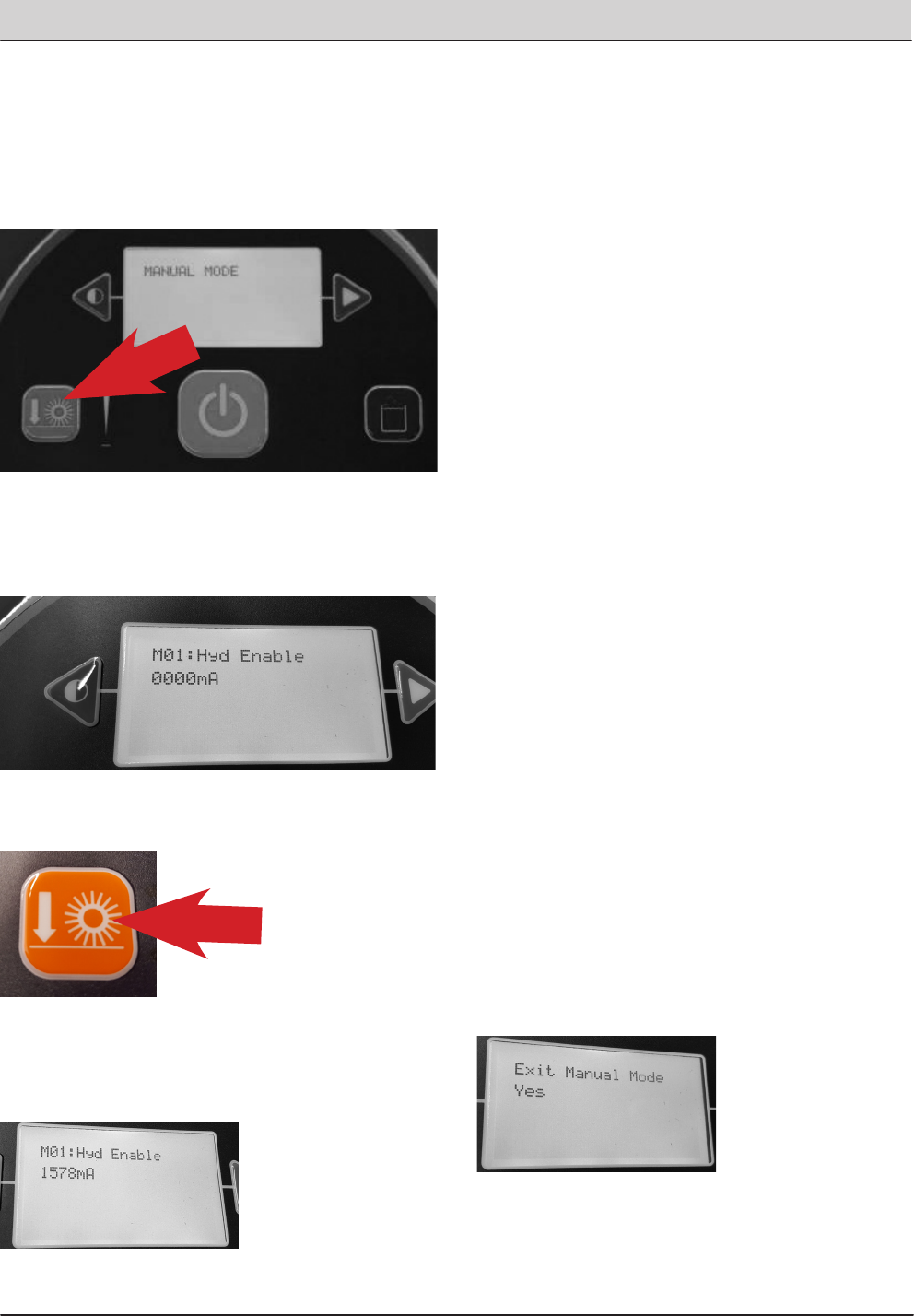
T20 Service Information (5-2017) 159
SERVICE
MANUAL MODE
1. Enter the Service Mode (See SERVICE MODE)
and if needed, press the right arrow to scroll to
the ,MANUAL MODE screen.
2. To enter the Manual Mode, press the ‘Orange
Down Pressure Button’ .
3. The rst Component displayed in Manual Mode
is the Hydraulic Enable Valve. It is turned off so
there is 0000mA being delivered to the solenoid
valve.
4. To turn on the Hydraulic Enable solenoid valve,
press the Orange Down Pressure Button.
5. When a component is turn on, the amperage
being output to that component, or the RPM of
that component is displayed and testing can be
done.
6. With the current component turned off, you can
advance to another component by pressing the
right arrow.
7. There are many components that can be turned
on and off, so testing can be done.
• M01: Hyd Enable = Hydraulic Enable
• M02: MB Down Act = Main Brush Down Actuator
• M03: MB ON Motor = Main Brush Motor ON
• M04: MB DP PWM = Main Brush Down Pressure
• M05: MB WaterVlv - Main Brush Water Valve
• M06: SB Ext. Act = Side Brush Extend Actuator
• M07: SB Down Act = Side Brush Down Actuator
• M08: SB ON Motor = Side Brush Motor ON
• M09: SB DP PWM = Side Brush Down Pressure
• M10: SB WaterVlv = Side Brush Water Valve
• M11: Water Vac = Water Vacuum
• M12: Dust Vac = Dust Vacuum
• M13: Squeegee Act = Squeegee Actuator
• M14: Hopper Valve1 -= Hopper Valve 1
• M14: Hopper Valve2 = Hopper Valve 2
• M15: Hp Latch = Hopper Latch
• M16: Hp Door = Hopper Door
• M17: Shaker - Shaker
• M18: Reverse = Reverse Sensor
• M19: Shutdown = Shutdown Relay
• M20: Alarm = Alarm
• M21: Horn = Horn
• M22: Det Pump = Detergent Pump
• M23: Alt Pump = Alternate Pump
• M24: AltHighFlow = Alternate High Flow
• M25: AltSideBrush = Alternate Side Brush
• M26: Sol AutoFill = Solution Auto Fill
• M27: Rec AutoFill = Recovery Auto Fill
• M28: Engine Speed = Engine RPM
Note: If a component is not installed on the machine,
the message ‘Not Installed’ is displayed.
8. To Exit Manual Mode, press the right arrow until
you see ‘Exit Manual Mode’, then press the
Orange Down Pressure Button Twice, or turn off
the key switch.
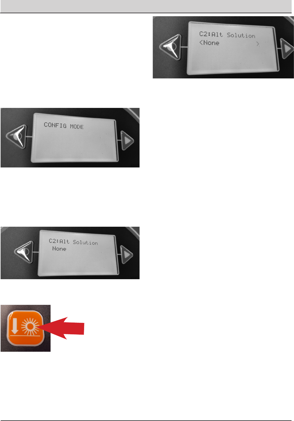
160 T20 Service Information (5-2017)
SERVICE
CONFIGURATION MODE
Configuration Mode is an onboard diagnostic utility
that configures controller software to operate optional
equipment and to electronically adjust certain output
functions.
1. Enter the Service Mode (See SERVICE MODE)
and press the right arrow to scroll to the CONFIG
MODE screen.
2. To enter the CONFIG MODE, press the Orange
Down Pressure Button’.
3. The C1: MainBrushHead choice feature is used
on the T20 machines. You can choose Disk or
Cylindrical Scrub Head Type..
4. Press the right arrow to scroll to the next
conguration option, in this example we will
explore setting the ‘Alternate Solution Options’.
5. Press the ‘Orange Down Pressure Button’ to
allow changing the Alternate Solution setting.
6. Press the ‘right arrow until the correct Alternate
Solution’ is displayed and press the Orange
Down Pressure Button to accept the change.
The Alternate Solution Options are:
• None
• EcH2O
• ES
• FaST
Choose the option that is installed on the machine.
7. To congure other options on the machine,
continuously press the right arrow to scroll to
the desired conguration option and press the
‘Orange Down Pressure Button ’ to choose that
option and adjust the settings.
The configuration options are:
• C1: MainBrushHead = Scrub Head Type
• C2: Alt Solution = Alternate Solution
• C5: Side Brush = Side Brush Type
• C6: Seat Switch = Seat Switch Installed?
• C7: Water Level = Solution Flow Rate
• C8 IRIS Module = IRIS Module Installed?
• C9: Run-In. Mode = End of Line Factory Use
• C10: Neut. Scrub = Neutral Scrub Enabled?
Additional Water Level Setting Information:
There are three water level range setting options.
• Economy
• Normal
• Heavy
When a settings is chosen, the operator can adjust
three flow rate settings within that range.
8. After all of the ‘Conguration’ settings have been
made. Press the right arrow until you see ‘Exit
Conguration Mode’, then press the Orange
Down Pressure Button Twice, or turn off the key
switch.
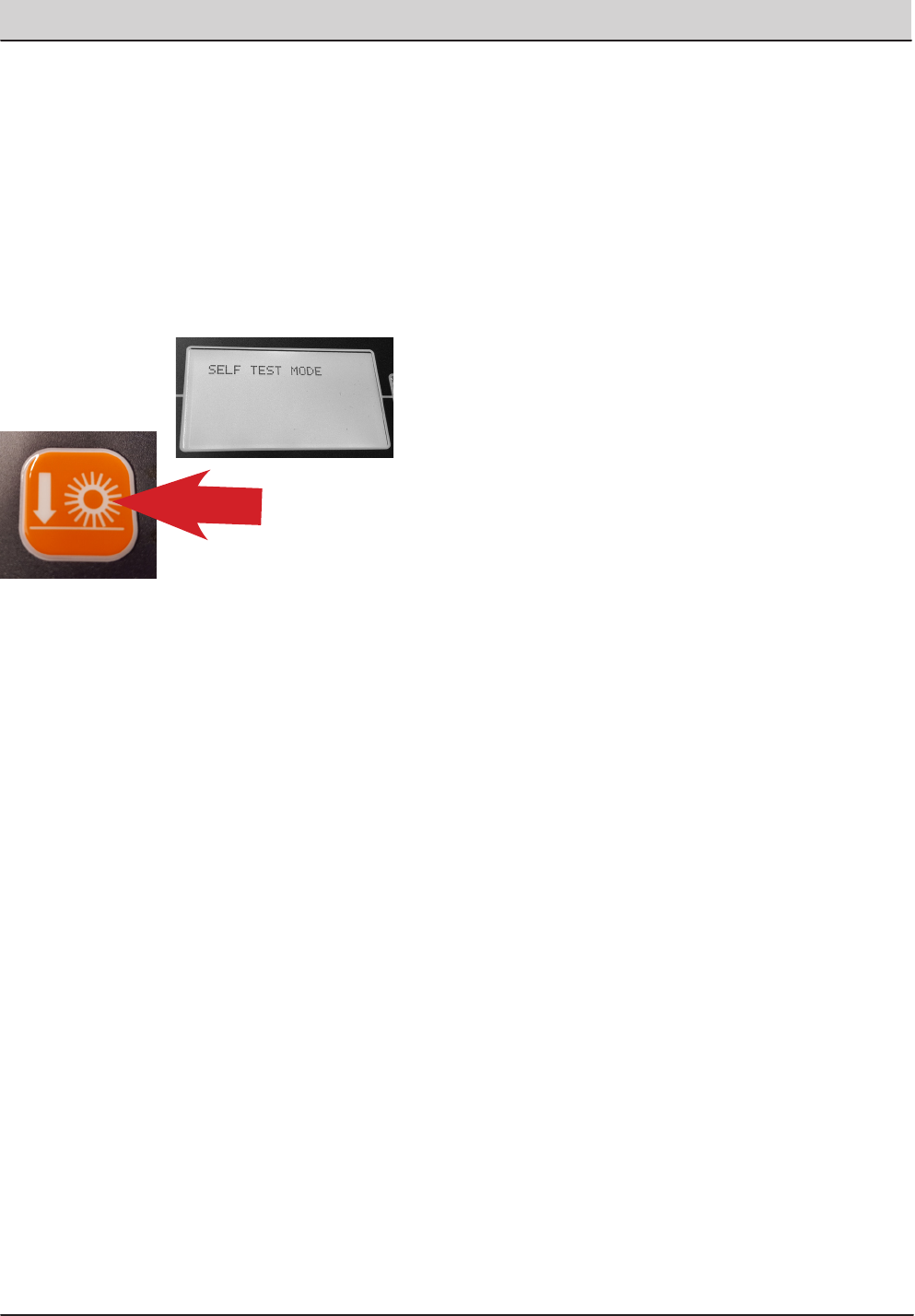
T20 Service Information (5-2017) 161
SERVICE
SELF TEST MODE
Self Test Mode is an onboard diagnostic utility
that tests for open or shorted output circuits. Once
completed, open and/or shorted output faults, are
displayed.
1. Enter the Service Mode (See SERVICE MODE)
and press the right arrow to scroll to the SELF
TEST MODE screen.
2. To enter the SELF TEST MODE, press the
‘Orange Down Pressure Button’.
3. The self test will automatically begin.
CAUTION: Many of the machine functions
will automatically turn on. Stay clear of
the machine during the self test.
These are a few examples of the tests performed
during the Self Test process. The table on the next
page shows all of the test names and descriptions.
• Test Hydraulic Enable Valve
• Test Main Brush Down Actuator
• Test Main Brush Motor
• Test Main Brush PWM Valve
• Test Main Brush Water Valve
Some of the tests listed will only be performed if the
machine has that specific option and it is configured
correctly.
4. When the self test is completed, faults found will
be displayed as an open or shorted load.
5. If faults exist, continually press the right arrow
icon to display all faults found.
If there are no other faults found or no faults found
initially, ‘Self Test End’ is displayed. Pressing the
right arrow again will display any faults found again.
All successful tests performed will result in the message
‘Done’. This indicates that test passed.
If a fault is found during the ‘Self Test’ , either ‘Open’ or
‘Short’ will be displayed for that test.
“Open” (Indicates current could not be delivered to
that circuit). There is an Open Load.
“Short” (The current draw is over the threshold, indi-
cating a short circuit)
Follow the diagnostic steps in this manual for diag-
nosing an open or shorted circuit.
6. To exit the self test mode, turn o the machine key.
The machine will return to normal operational mode
when the key switch is turned on again.

162 T20 Service Information (5-2017)
SERVICE
Self Test Name: Test Description:
1:Enable Hydraulic Valve Test the valve which enables machine hydraulics.
2:MBrush Down Actuator Tests the valve which controls ‘Main Brush Down’ actuation.
3:MBrush Motor... Tests the valve which controls the Main Brush motor
4:MBrush PWM Valve Tests PWM control of the Main Brush Down valve (for down pressure control).
5:MBrush Water Valve Tests the valve which controls solution delivery to the Main Brush.
6:SBrush Down Actuator Tests the valve which controls ‘Side Brush Down’ actuation.
7:SBrush Ext Actuator Tests the valve which controls ‘Side brush Extension’ actuation.
8:SBrush Motor... Test the valve which controls the Side Brush motor.
9:SBrush PWM Valve Tests PWM control of the Side Brush Down valve (for down pressure control).
10:SBrush Water Valve Tests the valve which controls solution delivery to the Side Brush
11:Scrub Vacuum Fan Tests the vacuum fan for the scrub subsystem (‘water pickup fan).
12:Sweep Vacuum Fan Tests the vacuum fan for the sweep subsystem.
13: Squeegee Actuator Tests the valve which controls the Squeegee Actuator.
14: SolTnk AF Tests the Autoll valve for the Solution Tank. (If Equipped)
15:RecTnk AF Tests the Autoll valve for the Recovery Tank. (If Equipped)
16:Reverse Relay Tests the relay for reverse driving.
17:Shaker Relay Tests the relay for the lter shaker.
18:Horn Horn test.
19:Alarm Backup alarm test.
24:Detergent Pump Tests the detergent pump.
25:Alt Pump Tests the Alternative Solution pump (FAST). (If Congured)
26:Alt High Flow Tests the High Flow Rate function of FAST. (If Congured)
27:Alt Side Brush Tests the valve which controls alternative solution (FAST/ECH2O) to the Side
Brush. (If Congured)
28:Shutdown Relay Tests the emergency engine shutdown relay.
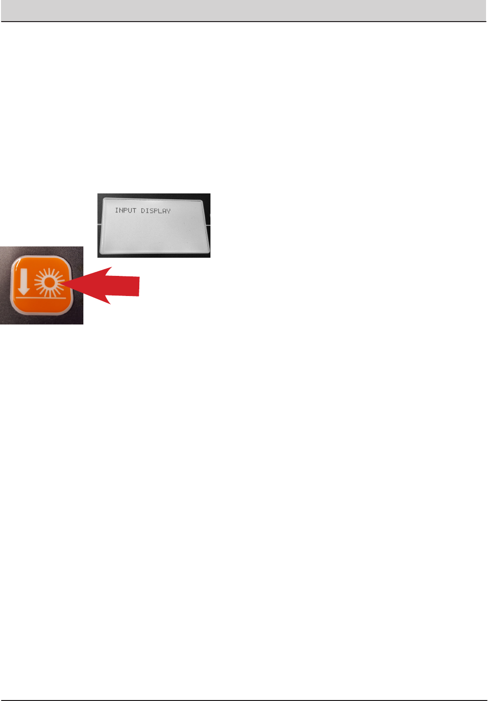
T20 Service Information (5-2017) 163
SERVICE
INPUT DISPLAY MODE
Input Display Mode is an onboard diagnostic utility
that displays controller input conditions. Input Display
Mode displays text messages for hard-wired switch,
sensor, and touch panel button inputs.
1. Enter the Service Mode (See SERVICE MODE)
and press the right arrow to scroll to the INPUT
DISPLAY MODE screen.
2. To enter the INPUT DISPLAY MODE, press the
‘Orange Down Pressure Button’.
3. The display will indicate the switch or sensor
being tested. When the position of the switch or
the state of the sensor is changed, the results of
that change is displayed.
The components that can be tested with Input
Display Mode Include:
• I1: SolTnk Empty
• I2: SolTnk Full
• I3: RecTnk Full
• I4: RedTank 1/2Full
• I5: Clogged HpFlt
• I6: CloggedHydFlt
• I7: ThermalSentry - Hopper Fire
• I8: Seat Switch
• I9: Brake Switch
• I10: HighEngTemp
• I11: Low Oil Psr
• I12: Check Engine
• I13: EcH2o Green
• I14: EcH2o Red
• I15: Hp Position
• I16: FilterShaker
• I17: Hp Up Rocker
• I18: HPDownRocker
• I19: HpDoor Open
• I20: HPDoor Close
• I21: Alternator
• I22: Throttle
• I23: Fuel Sender
• I24: Hyd Temp
• Exit
4. To Exit the Input Display Mode, press the right
arrow until you see ‘Exit Input Display Mode’,
then press the Orange Down Pressure Button
Twice, or turn off the key switch.
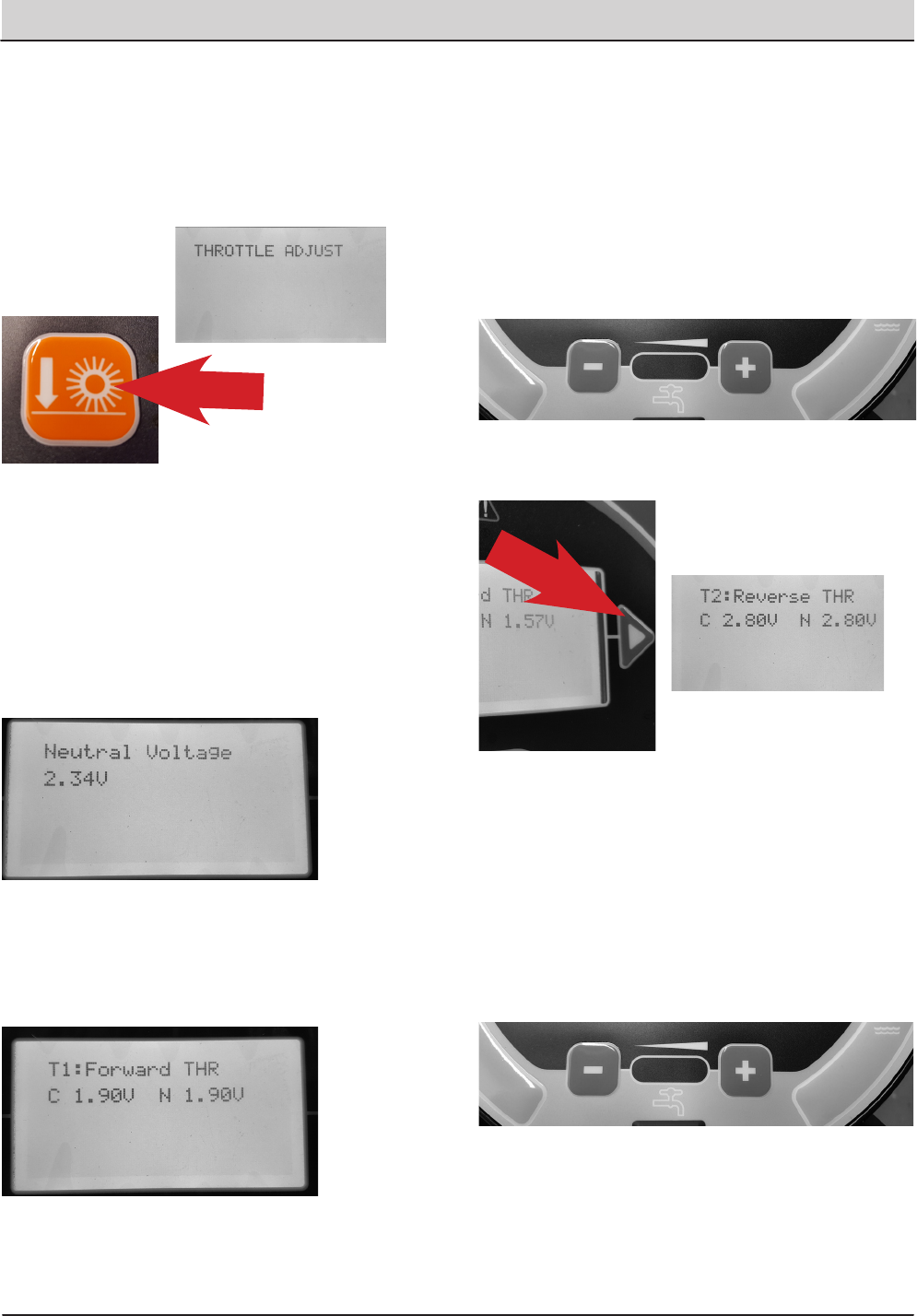
164 T20 Service Information (5-2017)
SERVICE
THROTTLE ADJUST MODE
1. Enter the Service Mode (See SERVICE MODE)
and press the right arrow to scroll to the
THROTTLE ADJUST MODE screen.
2. To enter the THROTTLE ADJUST MODE, press
the ‘Orange Down Pressure Button’.
3. The actual ‘Neutral Voltage’ value of the throttle
position sensor is displayed. Pressing the
‘Orange Down Pressure Button’ sets the Forward
and Reverse sense voltage values, based on this
Neutral Voltage value.
The machine operation should be tested to confirm
the rear squeegee raises and lowers at the proper
times when the machine is propelled forward and
backward.
4. If the rear squeegee raises and lowers too soon
or too late, you will need to adjust the Forward
voltage value and/or the Reverse voltage value.
Press the right arrow to proceed to the Forward
Threshold voltage value.
Note: the ‘C’ indicates the Current voltage value
and the ‘N’ indicates the New voltage value you are
setting.
5. Press the ‘minus’ icon to reduce the N (New)
value and the ‘Positive’ icon to increase the N
value.
The higher the Forward THR value, the quicker the
system will react to forward direction movement. Press
the Orange Down Pressure Button’ to make your ‘N’ New
value the ‘C’ Current value.
6. Press the right arrow to proceed to the Reverse
Threshold voltage value.
7. If the Reverse Threshold requires adjustment
press either the ‘minus’ icon to reduce the N
voltage or the ‘plus’ icon to increase the N
voltage.
The lower the value, the quicker the system will react to
reverse direction movement.
Once the desired setting is achieved, press the ‘Check
Mark’ to accept the change and conrm proper machine
operation.
8. To Exit the Throttle Adjust Mode, press the right
arrow until you see ‘Exit Throttle Adjust Mode’,
then press the Orange Down Pressure Button
Twice, or turn off the key switch.
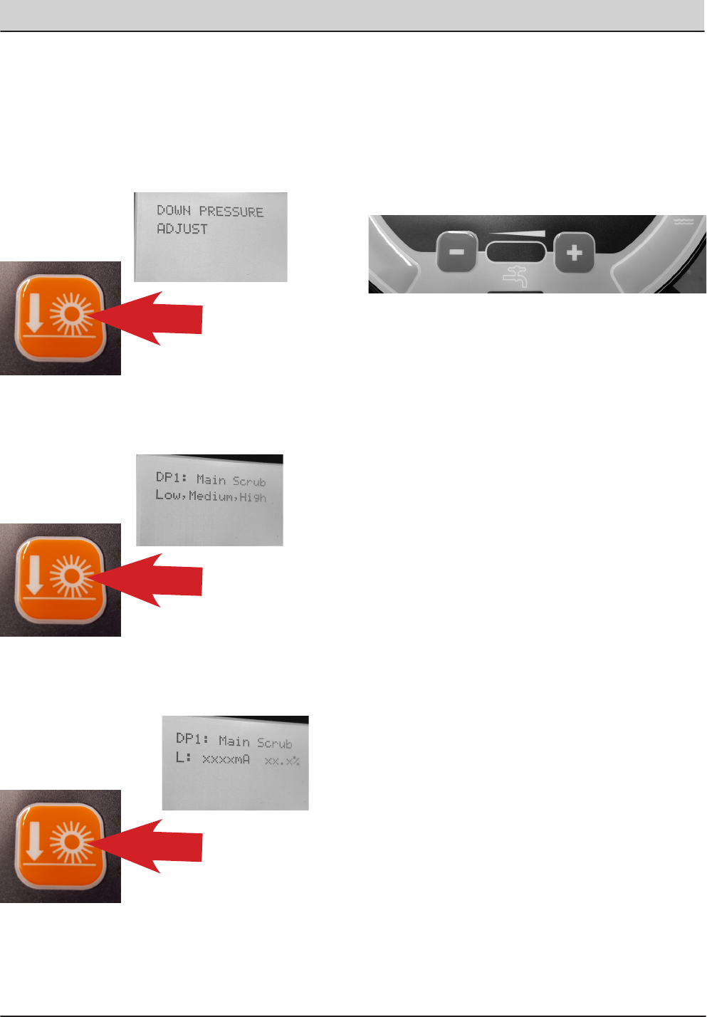
T20 Service Information (5-2017) 165
SERVICE
DOWN PRESSURE ADJUST MODE
1. Enter the Service Mode (See SERVICE MODE)
and press the right arrow to scroll to the DOWN
PRESSURE ADJUST MODE screen.
2. To enter the DOWN PRESSURE ADJUST
MODE, press the ‘Orange Down Pressure
Button’.
3. To enter the DOWN PRESSURE ADJUST MODE
for the Main Scrub Brushes, press the ‘Orange
Down Pressure Button’ , again.
4. To enter the ‘L’ (Low Down Pressure Setting
Mode) for the Main Scrub Brushes, press the
‘Orange Down Pressure Button’ , again.
Note: With the setting numbers displayed for the
Low main Scrub Brush Pressure adjustments can be
made to that setting.
Note: The electrical signal transmitted to the control
solenoid is measured in mA (milliamperes).
5. To increase the Low Setting Down Pressure for
the Main Scrub Brushes, press the ‘Plus’ icon to
increase the mA setting for the control valve. To
decrease the pressure, press the ‘Minus’ icon
to decrease the mA setting for the control valve.
Each time an icon is pressed, the electrical signal
to the solenoid is changed.
6. To allow adjustment to the Medium down
pressure setting, press the ‘Orange Down
Pressure Button’ to move backwards, then the
‘Right Arrow’ to move to the M: (Medium Down
Pressure Setting) then press the ‘Orange Down
Pressure Button’ to allow you to set the Medium
down pressure setting, if desired.
7. To allow adjustment to the High down pressure
setting, press the ‘Orange Down Pressure Button’
to move backwards, then the ‘Right Arrow’ to
move to the H: (Heavy Down Pressure Setting)
then press the ‘Orange Down Pressure Button’
to allow you to set the Heavy down pressure
setting, if desired.
8. When all down pressure adjustments are
completed for the Main Scrub Brushes, press
the ‘Orange Down Pressure Button’ to move
backwards, then the ‘Right Arrow’ to move to the
Main Scrub Exit.
9. Press the ‘Orange Down Pressure Button’ to Exit
the Main Scrub Down Pressure Setting Mode.
10. Press the ‘Right Arrow’ button to move to
the Side Scrub Brush Down Pressure Adjust
Mode. Follow the same process as above to
make adjustments to the Side Scrub Brush
Down pressure, if desired. You can press the
‘Right Arrow’ button again to move to the Main
Sweeping Brush Down Pressure Adjust Mode
and again for the Side Sweeping Brush Down
Pressure Adjust Mode.
Follow the same adjustment procedures outlined for
the Main Scrub Brush Down Pressure Settings.
NOTE: The factory default down pressure settings
are shown in the list below.

166 T20 Service Information (5-2017)
SERVICE
Default Down Pressure List:
Note: There is a low limit of 100mA and a high limit of
950mA for each brush pressure setting.
Main Scrub Brushes:
• Disk Low Pressure Default Setting, 358mA.
• Disk Medium Pressure Default Setting, 458mA.
• Disk High Pressure Default Setting, 548mA.
• Cyl. Low Pressure Default Setting, 340mA.
• Cyl. Medium Pressure Default Setting, 440mA.
• Cyl. High Pressure Default Setting, 530mA.
Side Scrub Brush:
• Low Pressure Default Setting, 600mA.
• Medium Pressure Default Setting, 675mA.
• High Pressure Default Setting, 730mA.
11. To exit the Down Pressure Adjust Modes, press the
Right Arrow until you see Exit DP Adjust. Press the
‘Orange Down Pressure Button’ twice to exit this
mode.
12. To exit the Service Modes, turn o the key switch
and then turn it on again.
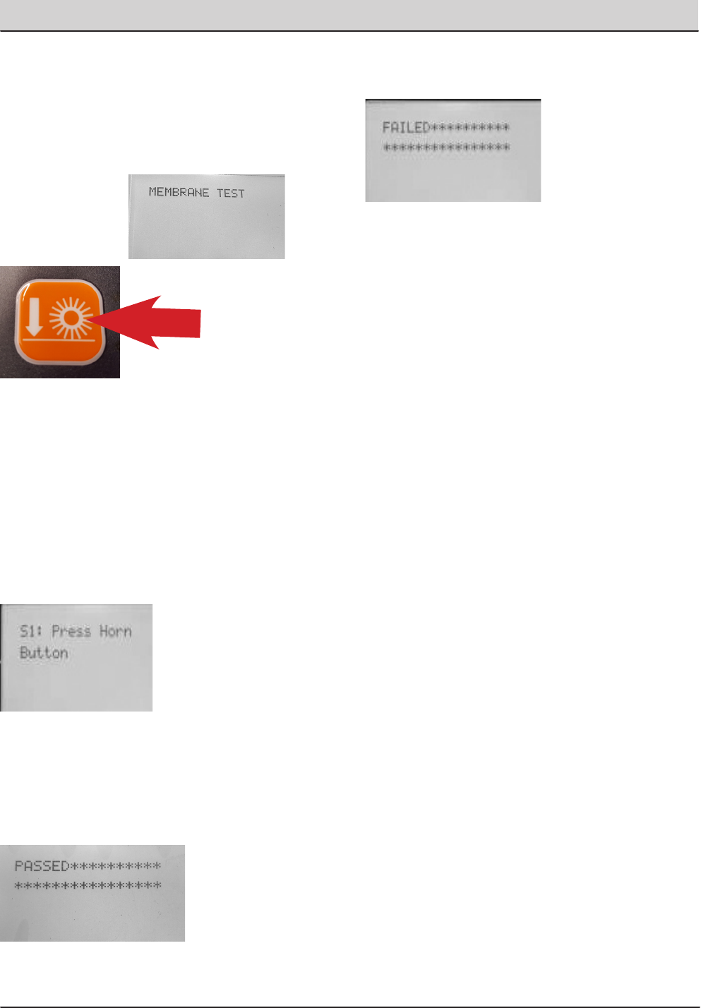
T20 Service Information (5-2017) 167
SERVICE
MEMBRANE TEST MODE
1. Enter the Service Mode (See SERVICE MODE)
and press the right arrow to scroll to the
MEMBRANE TEST MODE screen.
2. To enter the MEMBRANE TEST MODE, press
the ‘Orange Down Pressure Button’.
3. The MEMBRANE TEST MODE allows you to test
the touch button functions, on the control panel.
When you are in the Membrane Test Mode, you are
directed to press each Membrane Button to test it’s
functionality.
NOTE: If you delay too long prior to pressing the
required button, this delay may be reported with a
‘Failed’ message, in the display. If this happens, turn
off the key switch and restart all Membrane testing
procedures.
4. When you press a button as directed, if the
button functions properly, you will be directed
to press another button until all button tests are
completed. If all of the tests were completed
successfuly, you will receive the message
‘Passed’ in the display window.
5. If a button fails to function as designed, you will
receive the message ‘FAILED’ in the display
window.
6. To exit the Service Modes, turn o the key switch
and then turn it on again.
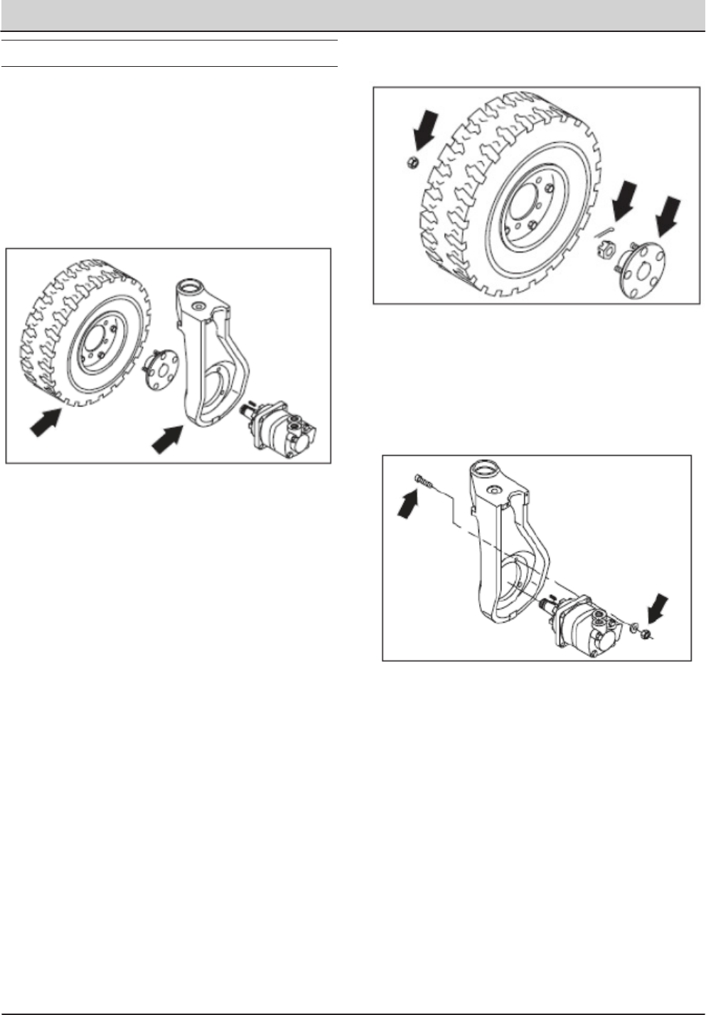
168 T20 Service Information (5-2017)
SERVICE
FRONT TIRE AND WHEEL SUPPORT
The front wheel support pivots the front wheel. The
support has one grease fitting for the bearings. The
front wheel support bearings must be lubricated
every 200 hours of operation. Use Lubriplate EMB
grease (TENNANT part no. 01433-1). Torque the
front wheel nuts to 142 -156 Nm (105 -115 ft. lb.)
after the first 50-hours of operation, and every 800
hours thereafter. Torque the front wheel hub nut to
(375 ft. lb.).
TO REPLACE FRONT DRIVE MOTOR
FOR SAFETY: Before Leaving Or Servicing
Machine; Stop On Level Surface, Set Parking
Brake, Turn Off Machine And Remove Key.
1. Engage parking brake, block rear tires.
2. Jack up front of machine. Use jack stands to
support machine.
FOR SAFETY: Block machine tires before jacking
machine up. Jack machine up at designated
locations only. Block machine up with jack
stands.
3. Remove the front tire and wheel assembly.
4. Remove the cotter pin and slotted nut from the
front wheel drive motor shaft.
5. Use a puller to remove the drive hub from the
tapered shaft of the drive motor.
6. Remove and plug the hydraulic hoses leading to
the front wheel drive motor.
7. Remove the four drive motor mounting bolts.
8. Slide the motor out of front wheel housing.
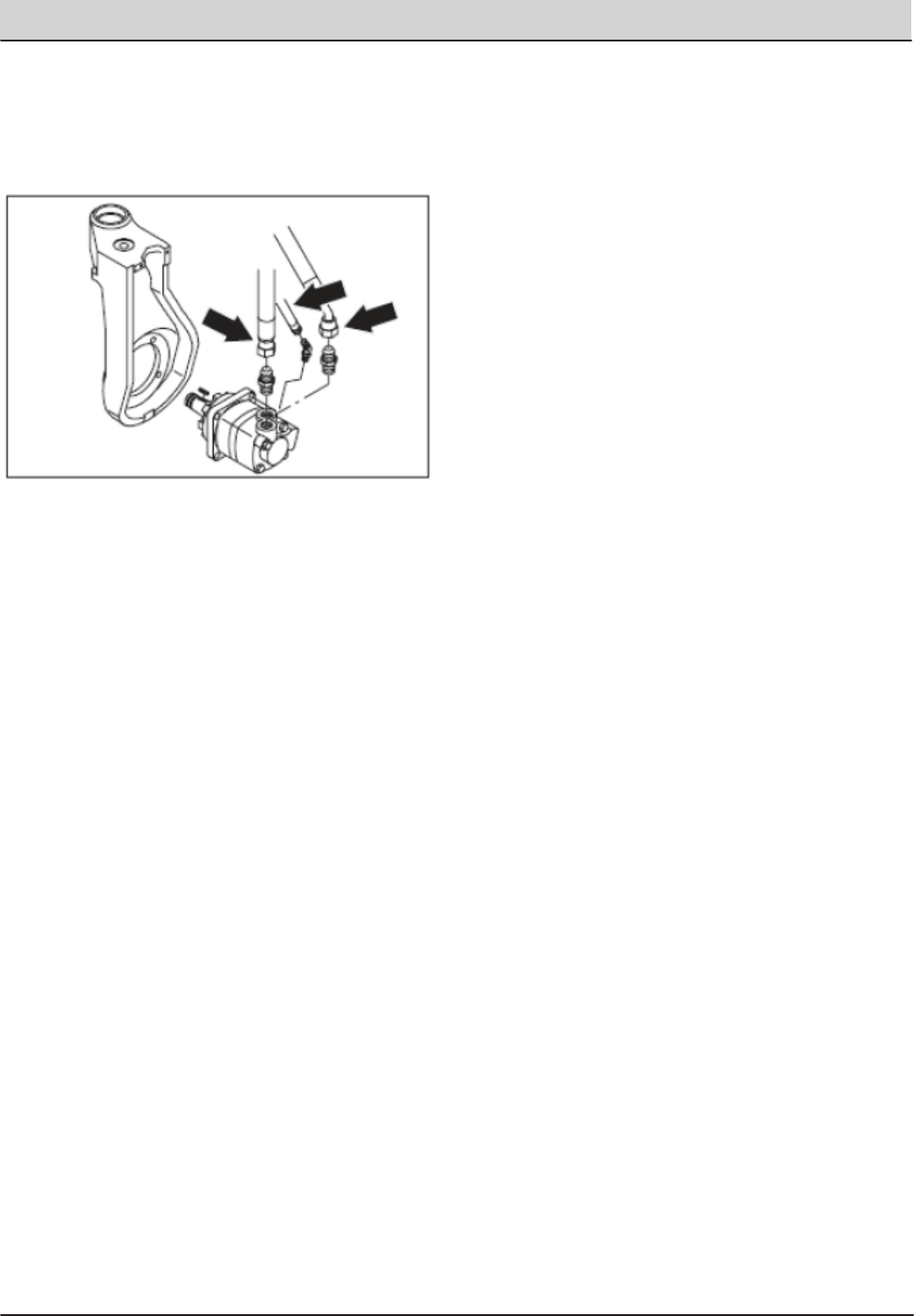
T20 Service Information (5-2017) 169
SERVICE
NOTE: Observe hydraulic cleanliness requirements
when opening hydraulic lines.
9. Remove the hydraulic ttings from the old
motor and install in the new motor in the same
orientation.
10. Slide the new motor in the front wheel housing.
Note the orientation of the motor.
11. Reinstall the four socket-head screws. Torque to
90 - 117 Nm (70 - 85 ft lb).
12. Reconnect the hydraulic hoses to the drive motor.
NOTE: Make sure the square key is in place on the
shaft of the new motor.
13. Mount the drive hub to tapered motor shaft.
Tighten slotted nut to 500 Nm (375 ft. lb). Install
the cotter pin.
14. Install the front tire. Torque the front wheel nuts
to 142 - 156 Nm (105 -115 ft. lb).
15. Remove jack stands and lower machine.
16. Operate the machine and check the front drive
motor for any leaks.

170 T20 Service Information (5-2017)
SERVICE
