Swisher 97 056001 Users Manual AZ_Series_Zero_Turning_Riders_1997 2003_11 10 98
!! Swisher-3 Swisher Lawn Mower Manuals - Lawn Mower Manuals – The Best Lawn Mower Manuals Collection
AZ Series to the manual 75be497f-4a74-4e9b-874b-a578285bfe41
2015-02-02
: Swisher Swisher-97-056001-Users-Manual-448931 swisher-97-056001-users-manual-448931 swisher pdf
Open the PDF directly: View PDF ![]() .
.
Page Count: 36
MODEL NO.
All AZ Series
Models from
Serial #
97-056001
OWNER’S
MANUAL
Assembly
Operation
Service and Adjustment
Repair Parts
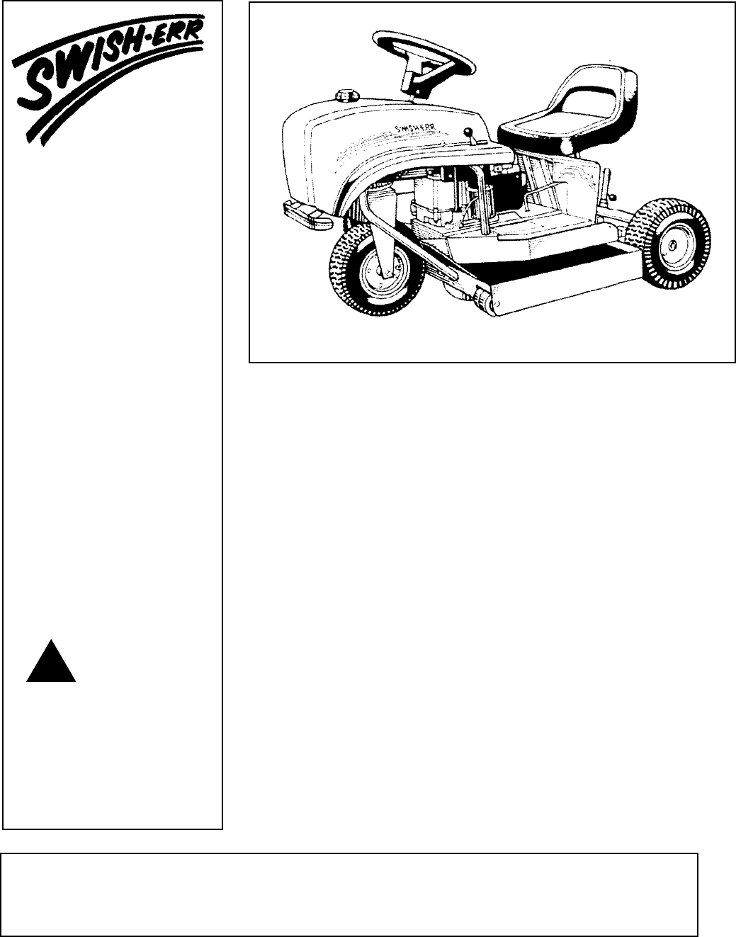
Zero Turn
Riding Mowers
P.O. BOX 67, WARRENSBURG, MISSOURI 64093 PHONE 660-747-8183 FAX 660-747-8650 Made In The
USA
!CAUTION:
Manufacturing quality lawn care equipment since 1945
Read and follow all
Safety Rules and
Instructions Before
Operating This
Equipment
Rev. 12.01.1997

Dear Valued Customer:
All of us at our plant in Warrensburg, Missouri, are delighted that youve chosen to purchase a Swisher Zero
Turn Radius Mower. We know that you will enjoy years of trouble free service and will save time and money
by using our products. We regularly receive letters from satisfied riding mower customers who are still using
Swisher mowers they purchased 20, even 25 years ago!
American-Made Swisher mowers feature rugged all-steel construction, and include 1/8 inch welded steel mower
decks. Swisher mower decks are individually fabricated, therefore far more durable than stamped steel decks
commonly found on other mowers. In addition to unsurpassed durability, their unique patented steering pro-
vides maximum maneuverability with time saving, zero-turning radius capability.
Founded a half-century ago, Swisher is a family-owned and operated company dedicated to quality and prod-
uct innovation. We designed and introduced the first zero-turning radius walk-behind mower in 1945, and the
first zero-turning radius riding mower in 1955...long before most other mower manufacturers began business.
Our innovations have continued with popularizing the towing mower concept, solar-automated composters,
rotisserie outdoor cooking and much more!
Please take the time to familiarize yourself with this owners manual paying special attention to the safety
precautions, the operation and the maintenance of your new riding mower.
We appreciate the trust you have placed in our company and our product. Thank you for your business.
Sincerely,
O. Wayne Swisher
President,
Swisher Mower and Machine Co., Inc.
Proven Performance Since 1945
Phone (660) 747-8183
Toll Free (800) 222-8183
FAX (660) 747-8650
Swisher Mower & Machine Co. Inc.
P.O. Box 67
Warrensburg, MO 64093
TABLE OF CONTENTS
Safety Rules ............................................................................................... 2
Safety /Operational Decals ........................................................................ 4
Assembly .................................................................................................... 6
Your New Mower....................................................................................... 8
Before Starting Engine - Frist Time .......................................................... 8
Maintenance ............................................................................................. 10
Adjustments/Lubrication ......................................................................... 11
Storing ...................................................................................................... 12
Repairs ...................................................................................................... 12
Mulching Mower ..................................................................................... 14
Sweeper/Collector .................................................................................... 14
Brush Adjustments ................................................................................... 15
Bag and Brush Replacement.................................................................... 15
Mower Installation ................................................................................... 16
Belt Housing Illustration ......................................................................... 17
Two Speed Pulley Illustration.................................................................. 18
Variable Speed Pulley Illustration ........................................................... 19
Height Adjustment Illustration ................................................................ 20
Blade Drive Assembly Illustration .......................................................... 21
Traction Assembly Illustration ................................................................ 22
Two Speed Pulley Assembly Illustration................................................. 23
Mulcher Mower Assembly Illustration ................................................... 24
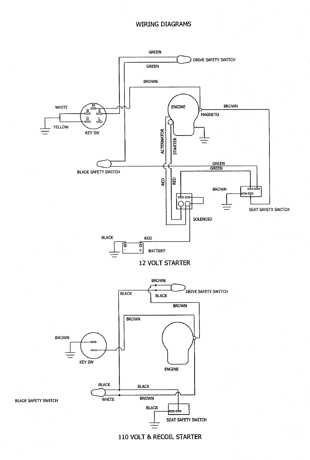
Wiring Diagram Illustration..................................................................... 25
Replacement Parts .................................................................................... 26

2
SAFETY RULES
Safety Operation Practices for Riding Mowers
IMPORTANT: THIS CUTTING MACHINE IS
CAPABLE OF AMPUTATING HANDS AND
FEET, AND THROWING OBJECTS. FAILURE
TO OBSERVE THE FOLLOWING SAFETY
INSTRUCTIONS COULD RESULT IN SERIOUS
INJURY OR DEATH.
I. GENERAL OPERATION
Read, understand, and follow all instructions in
the manual and on the machine before starting.
Read this operators manual carefully. Become
familiar with the controls and know how to
operate your mower properly.
Only allow responsible adults, who are familiar
with the instructions, to operate the machine.
Clear the area of objects such as rocks, toys,
wire, etc. which could be picked up and thrown
by the blade.
Be sure the area is clear of other people before
mowing. Stop machine if anyone enters the area.
Never carry passengers.
Do not mow in reverse unless absolutely
necessary. Always look down and behind before
and while backing.
Be aware of the mower discharge direction and
do not point it at anyone. Do not operate the
mower without the guards in place.
Slow down before turning.
Never leave a running machine unattended.
Always turn off blades, and stop engine.
Turn off blades when not mowing.
Mow only in daylight or good artificial light.
Do not operate the machine while under the
influence of alcohol or drugs.
Watch for traffic when operating near or crossing
roadways.
Use extra care when loading or unloading the
machine into a trailer or truck.
Disengage power to mower, stop engine when
transporting or not in use.
Exercise special care when mowing around fixed
objects in order to prevent the blades from
striking them. Never deliberately run tractor or
mower onto or over any foreign object.
Use mower only as the manufacturer intended
and as described in the manual.
Do not operate mower if it has been dropped or
damaged in any manner. Always have damage
repaired before using your mower.
Always wear safety glasses or eye shields when
starting and while using your mower.
Dress properly. Do not operate mower when
barefoot or wearing open sandals. Wear only solid
shoes with good traction when mowing.
Always make cutting height adjustments before
starting your mower. Never attempt to do this while
the engine is running.
Keep your eyes and mind on your mower and the
area being cut.
Do not let other interests distract you.
Do not put hands or feet near or under rotating
parts. Keep clear of the discharge opening at all
times.
Before cleaning, inspecting, or repairing your
mower, stop the engine and make absolutely sure
the blade and all moving parts have stopped. Then
disconnect the spark plug wire and keep it away
from the spark plug to prevent accidental starting.
Do not operate your mower if it vibrates
abnormally. Excessive vibration is an indication of
damage; stop the engine, safely check for the cause
of vibration and repair as required.
Never operate your mower without proper guards,
plates, or other safety devices in place.
II. SLOPE OPERATION
Slopes are a major factor related to loss-of-control and
tipover accidents, which can result in severe injury or
death. All slopes requires extra caution. If you feel
uneasy on it, do not mow it.
Look for this symbol to point out important
safety precautions. It means CAUTION!!!
BECOME ALERT!!! YOUR SAFETY IS
INVOLVED!!!
!
CAUTION:
ALWAYS DISCONNECT SPARK PLUG
WIRE AND PLACE IT WHERE IT
CANNOT CONTACT SPARK PLUG IN
ORDER TO PREVENT ACCIDENTAL
STARTING WHEN SETTING UP,
TRANSPORTING, ADJUSTING OR
MAKING REPAIRS.
!

3
Keep all movement on the slopes slow and
gradual. Do not make sudden changes in
speed or direction.
Avoid starting or stopping on a slope. If tires
lose traction, disengage the blades and
proceed slowly straight down the slope.
DO NOT:
Do not turn on slopes unless necessary, and
then, turn slowly and gradually downhill, if
possible.
Do not mow near drop-offs, ditches, or
embankments. The mower could suddenly
turn over if a wheel is over the edge of a cliff
or ditch, or if an edge caves in.
Do not mow on wet grass. Reduced traction
could cause sliding.
III. CHILDREN
Keep children out of the mowing area and
under the watchful care of another
responsible adult.
Be alert and turn machine off if children
enter the area.
Before and when backing, look behind and
down for small children.
Never carry children. They may fall off and be
seriously injured or interfere with safe machine
operation.
Never allow children to operate the machine.
Use extra care when approaching blind corners,
shrubs, trees, or other objects that may obscure
vision.
IV. SERVICE
Use extra care handling gasoline and other
fuels. They are flammable and vapors are
explosive.
- Use only an approved container.
- Never remove gas cap or add fuel with the
engine running.
- Allow engine to cool before refueling. Do
not smoke.
- Never refuel the machine indoors.
- Never store the machine or fuel container
inside where there is an open flame, such
as a water heater.
Never run a machine inside a closed area.
Keep nuts and bolts, especially blade attachment
nuts, tight and keep equipment in good condition.
Never tamper with safety devices. Check their
proper operation regularly.
Keep machine free of grass leaves, or other debris
build-up. Clean oil or fuel spillage. Allow machine
to cool before storing.
Stop and inspect the equipment if you strike an
object. Repair, if necessary, before restarting.
Never make adjustments or repairs with the engine
running.
Mower blades are sharp and can cut. Wrap the
blades(s) or wear gloves, and use extra caution when
servicing them.
DO:
Mow up and down slopes.
Remove obstacles such as rocks, tree
limbs, etc.
Watch for holes, ruts, or bumps. Uneven
terrain could overturn the machine. Tall
grass can hide obstacles.
Use slow speed. Choose a low gear so
that you will not have to stop or shift while
on the slope.
CAUTION:
TRAGIC ACCIDENTS CAN OCCUR IF
THE OPERATOR IS NOT ALERT TO
THE PRESENCE OF CHILDREN.
CHILDREN ARE OFTEN ATTRACTED
TO THE MACHINE AND THE MOWING
ACTIVITY. NEVER ASSUME THAT
CHILDREN WILL REMAIN WHERE YOU
LAST SAW THEM.
!

4
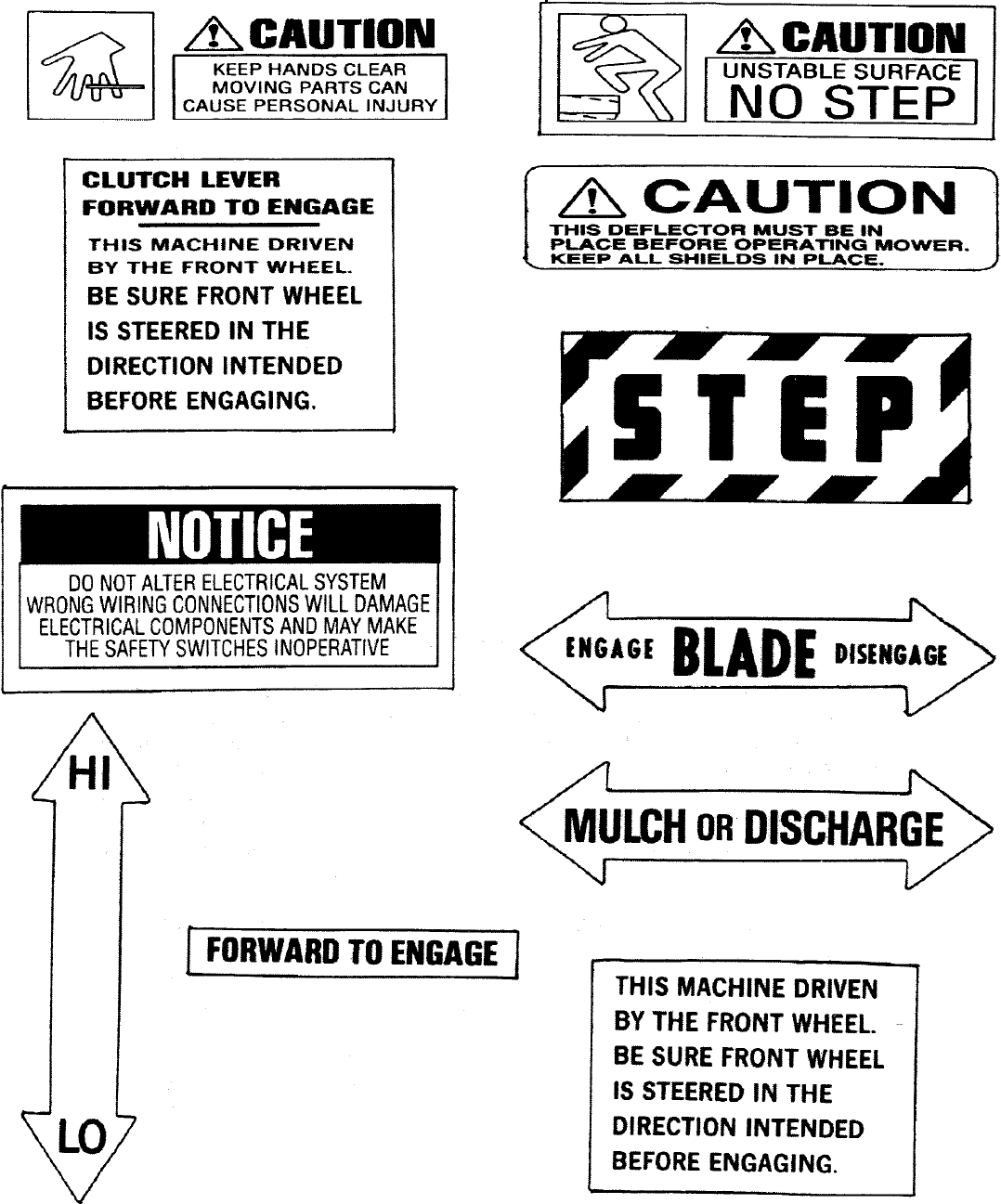
SAFETY AND OPERATIONAL DECALS
Replace decal immediately if damaged. Order by part number from
Swisher Mower and Machine Co. Inc.
WARNING
!
SERIOUS INJURY OR DEATH CAN OCCUR
- READ OPERATORS GUIDE FIRST -
DANGER
!
SPINNING BLADE
KEEP CLEAR
CONTACT CAN INJURE
5

6
IMPORTANT! - READ THIS MANUAL BEFORE OPERATING MOWER
Be sure to check your new Swisher Riding Mower for shipping damage before beginning assembly.
These parts are packaged with your new mower.
The following tools are needed for assembling your new Swisher Riding Mower:
- Steering Wheel - includes one (1) 1/4-20 x 1/2 bolt, washer and cap plug
- Seat - includes two (2) 3/8 - 16 x 3/4 bolts, washers, nuts
- Grass Chute ( for non-mulching mowers) with bolt, nut and spring
- Wheels
- Cotter Pins
Safety Glasses
1/2” box wrench
2 - 7/16” box wrenches
7/16” socket and ratchet
5/32” hex key wrench
ASSEMBLY
To assemble your new mower, complete ALL of the following steps.
Align the key in the steering wheel hub
with the slot in the end of the steering shaft
and press down.
Use a hex key wrench to install and tighten
the set screws on the side of the steering
hub.
Insert the 1/4-20 x 1/2” long bolt and
washer into the steering hub.
Tighten the bolt until snug. Do not over-
tighten
Install the cap plug to cover the bolt and
washer.
1. INSTALL STEERING WHEEL
•
•
•
•
•
Insert the axle through the hub of the wheel
with the valve stem facing away from the
mower. (Be sure to place the supplied
spacers between the surface of the axle
weldment and the hub to prevent the tire
from rubbing the weldment.)
With the wheel in position, insert a cotter
pin in the hole on the end of the axle. Use
pliers to spread the ends of the cotter pin
to retain the wheel in position. Repeat this
process for the other side.
Important - Do not forget to spread the
ends of the cotter pins to keep wheel as-
sembly in place.
1. INSTALLING THE WHEELS
7
3. CHECKING THE ENGINE
The engine has been serviced prior to ship-
ment. However, it is important to check
the oil level prior to starting the engine.
If more oil is required, follow the engine
manufacturer recommendations. Be
careful not to overfill.
IMPORTANT! GASOLINE SHOULD
BE ADDED OUTSIDE IN
A WELL VENTILATED AREA.
Add approximately one gallon of fuel to
the tank. Be certain to follow the engine
manufacturers recommendations on the
type of fuel to use.
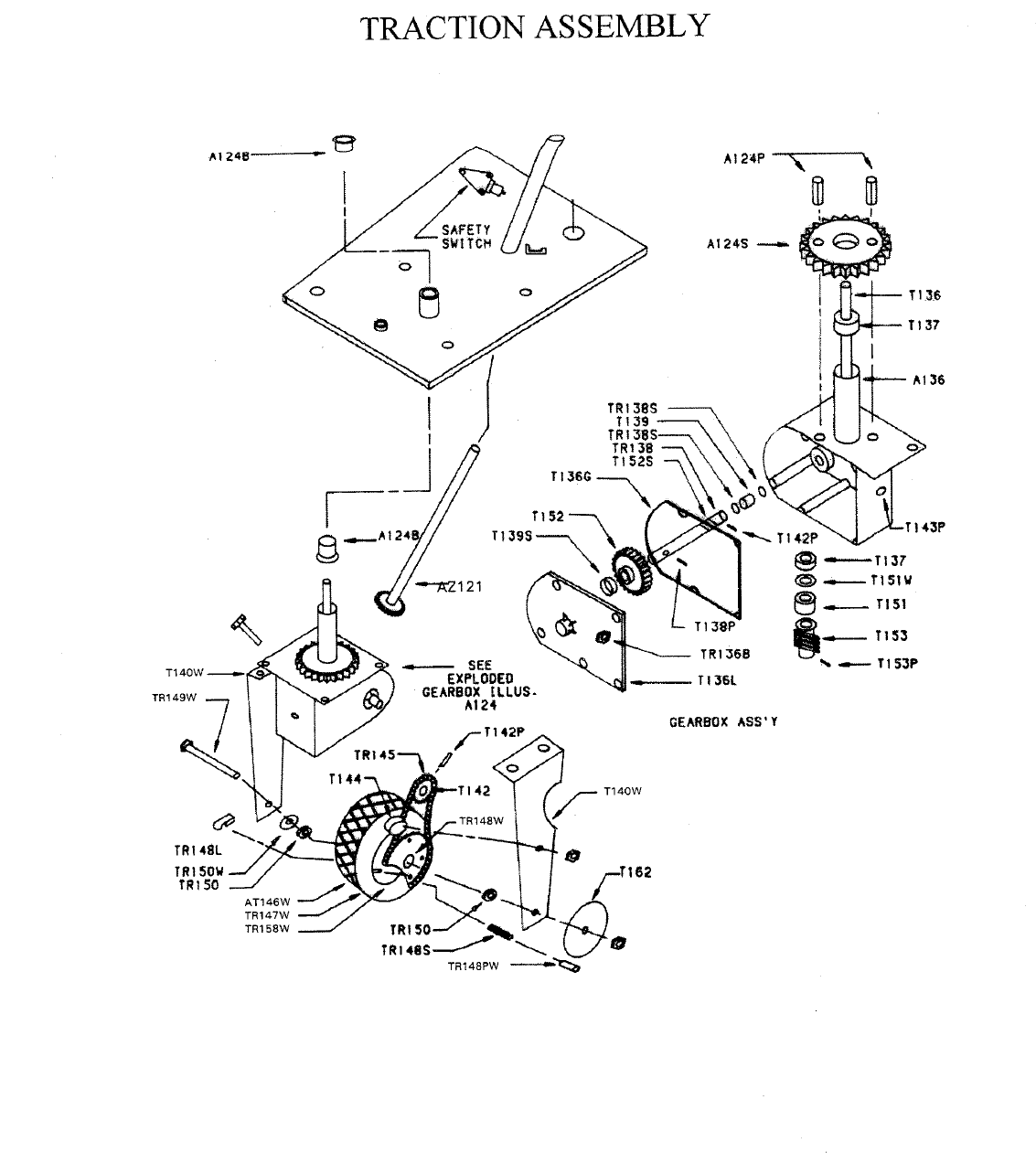
The gearbox is filled with lubricant at the
factory. However, verify that the gearbox
is filled by removing the Oil Check Plug
(Part #T143P) located on the side of the
gearbox.
The lubricant should be level with the oil
check plug opening.
If you need to add lubricant, use ONLY
TR125L, which is specially blended by
Swisher Mower and Machine Company.
4. ADD GASOLINE
5. CHECKING GEARBOX LUBRICANT
The seat should be installed using the two
(2) bolts and lock nuts supplied.
Attach the wiring from the mower to the
seat safety switch. Important! The wir-
ing must be connected to the seat safety
switch for the mower to operate.
On 12 volt models: attach green wires
and the brown wires to the two (2) remain-
ing positions on the safety switch.
On non-l2 volt models: attach the two
(2) brown wires to the safety switch.
The order of wire attachment or position
does not matter.
Attach the grass chute using the bolt, nut
and spring supplied. Important! Do Not
operate without the grass chute in place!
6. INSTALLING THE SEAT
7. INSTALLING THE GRASS CHUTE (for
non-mulching mowers only)

Check fuel and oil levels.
Make sure the Drive Control and Blade Clutch
Levers are pulled back and disengaged. Make sure
your foot is off the pedal.
Once engine is started, become familiar with the
steering and maneuvering of the mower before
engaging the blades.
The Lock Pin Lever (TR148L) should always be
engaged (flat against the wheel) BEFORE start-
ing the engine. To move the mower when en-
gine is not running, the Lock Pin Lever
(TR148L) must be disengaged.
Do not engage pin when engine is running. The
Lock Pin Lever (TR148L), located opposite the
8
BECOMING FAMILIAR WITH YOUR NEW SWISHER MOWER
Select an open area with no obstructions to complete the following steps which will help you familiarize
yourself with the location and movement of the mower controls. The engine SHOULD NOT be running as you
familiarize yourself with these controls.
RIGHT AND LEFT SIDES OF MOWER ARE DETERMINED BY SITTING IN THE DRIVERS SEAT.
OPERATOR POSITION
REAR
BE SURE TO READ THIS SECTION BEFORE STARTING THE
ENGINE FOR THE FIRST TIME
FRONT
DRIVE ENGAGEMENT PIN:
chain on the front wheel, is engaged when it is
resting flat against the front wheel.
The motion of the mower is controlled by the
Drive Clutch Lever (AZ125) located just be-
low the steering wheel, on the left side.
To engage the drive, start the engine.
Push the Drive Clutch Lever (AZ125), which
is located on the left side of the steering wheel,
forward. The mower will BEGIN MOVING
FORWARD IN THE DIRECTION THE
FRONT TIRE IS POINTED.
ENGAGING THE DRIVE:
Hand-Operated/Two-speed Drive:
(all models begin with AZ2)
RIGHT
LEFT
9
To disengage the drive, pull the Drive Clutch Le-
ver (AZ125) back.
The lever on the right side of the steering wheel
controls ground speed:
Low Speed: place the lever in the lower position
closest to the operator. This speed is excellent for
trimming and maneuvering in tight places.
High Speed: push the lever forward (away from)
the operator. This speed is used for mowing large
open areas.
To engage the drive, press your foot against the
pedal. The speed of the mower is regulated by
the amount of pressure against the foot pedal.
The mower automatically stops and brakes when
you lift your foot off the pedal.
The abruptness of the stop depends on how quickly
you take your foot off the pedal.
To engage the blades, move the lever toward the
front of the mower.
To disengage the blades, pull the lever toward the
rear of the mower.
ENGAGING THE BLADES:
Foot-Pedal Operated:
(all models begin with AZV)
The Blade Clutch (BR20AZ) is located on the left
side below the seat.
Reverse directions by simply turning the front
wheel in the direction you want to go.
To reverse directions in tight areas, pull back the
Drive Control Lever (AT125) to stop the mower.
Then turn the steering wheel 180 degrees (in the
opposite direction). Engage the Drive Lever once
again.
Swishers patented front wheel drive steering
mechanism provides 360 degrees of maneuverability.
THE ZERO-TURNING RADIUS
QUICK CHANGE MULCHING
MOWER:
WARNING!
ALWAYS STOP ENGINE AND DISCONNECT
SPARK PLUG WIRE BEFORE OPENING OR
CLOSING MULCHING CHUTE!
To use as a side-discharge mower:
To use as a mulching mower:
Twist knob to unlock chute, let chute open and
then twist knob to lock chute.
Twist knob, push chute closed and twist knob again
to lock.
Changing from low speed to high speed or from
high speed to low speed can be done without
disengaging the drive.
NEVER ADD GASOLINE TO A HOT EN-
GINE - ALLOW ENGINE TO COOL BE-
FORE ADDING GASOLINE.
10
MOWER MAINTENANCE
Make sure your mower is in safe working condition by keeping the following guidelines in mind every time you use
your mower.
Keep mower in good operating condition and keep
safety guards, shields and switches in place. DO
NOT operate mower if any of these devices are
missing.
Check all nuts, bolts and screws for secure fit to
keep equipment in safe working condition. Make
adjustments as necessary.
To reduce fire hazards, keep engine free of grass,
leaves or excessive grease.
DO NOT operate mower with damaged or miss-
ing muffler. DO NOT tamper with exhaust sys-
tem; this may create a fire hazard.
DO NOT operate engine if air cleaner or the cover
directly over the carburetor air intake is removed.
Removal of these parts could create a fire hazard.
Disconnect the battery before repairing the mower.
Before cleaning, making adjustments or repairing
mower, STOP engine and disconnect the Spark
Plug Wire. ALLOW THE ENGINE TO COOL.
To ensure the most even grass cut, keep the tire
pressure at 35 psi (pounds per square inch).
Handle gasoline with care. DO NOT smoke or
use open flame near gasoline. Use only approved
gasoline containers. Never fuel or run mower in
poorly ventilated area, such as a garage or utility
building.
Always replace fuel tank cap. Be sure to clean up
any spilled gasoline.
Do not change the engine governor settings or
overspeed the engine; severe injury or damage
may result.
Never store mower, with gasoline in the tank, in-
side a building where flames may reach an open
flame or spark. Always allow engine to cool be-
fore storing.
11
ADJUSTMENTS AND ROUTINE SERVICING
WARNING - ALWAYS STOP ENGINE AND DISCONNECT SPARK PLUG WIRE
AND BATTERY BEFORE MAKING ADJUSTMENTS OR SERVICING MOWER!
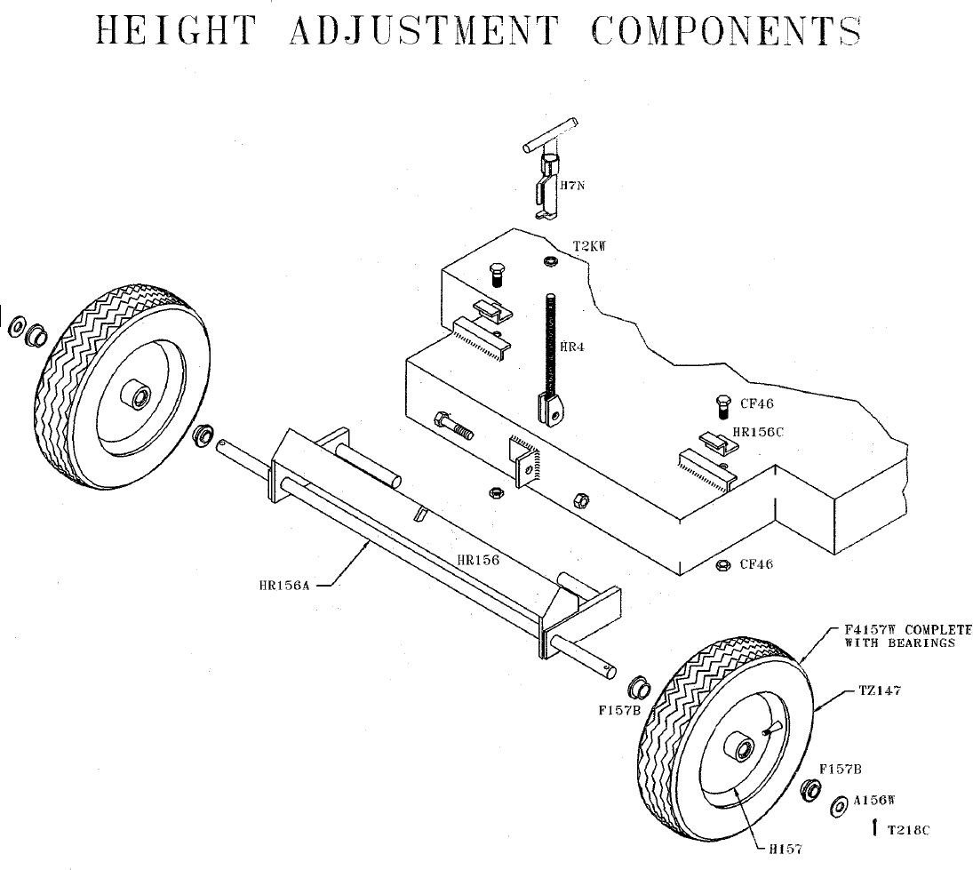
CUTTING HEIGHT ADJUSTMENT:
•Turn Height Adjustment Crank (H7N)
Clockwise to raise the blade
Counter-Clockwise to lower the blade.
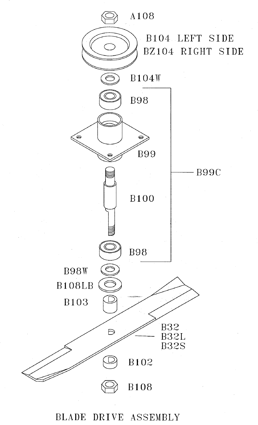
BLADE SHARPENING:
Remove Blade Nut (B108) from Blade Shaft (B100).
Remove blades (B32S and B32L) and the appropriate Blade Spacers (B101, B102 and/or B103).
Note the position of the spacers.
Sharpen the blades.
When reassembling, make certain that blade spacers are positioned so blade is still under mowing deck.
Replace the old Blade Nut (B108) with a new one. Make certain the nut and washer are tightened to a minimum
of 95 foot pounds.
LUBRICATION:
Wheel Bearings - Lubricate the Rear Wheel Bearings three times a year by putting a few drops of standard 30 weight
engine oil on each Wheel Bearing (F157B).
Blade Bearings - These bearings are sealed and do NOT require additional lubrication.
Gear Box - Located on the drive unit. After every twenty hours of operation, check the oil level by using the Oil
Check Plug (T143P) located on the front side of the Gear Box. The oil should be level with the Oil Check Plug. Use
only SWISHER Gear Oil (TR124L).
Seat Spring Rods (A153) - Lubricate with gun grease or petroleum jelly once a year.
Engine - Refer to your engine manual for engine lubrication care.
BELTS:
Occasionally check belts for wear. A worn belt should be replaced. See REPAIR (page 12) section for instructions.
12
Disconnect Spark Plug Wire
Drain the fuel.
Drain the oil and refill the crankcase with clean
oil.
Clean your mower. Brush off matted clippings
and caked-on dirt. Use a wire brush to clean
the underside of lawn mower. Use a cloth to
wipe away debris from the upper deck. If
available, use an air compressor to blow thatch
and dirt from hard to reach places.
STORING YOUR MOWER
Preparing your mower for storage in the fall will result in better operation and a longer life in the spring. It will
allow you plenty of time to order parts, make the needed repairs and check for proper operation before the
equipment is needed again in the spring. Parts may be obtained from your Swisher dealer or you may call our
factory at 800-222-8183 to order parts. The following procedures will help you store your mower in a proper
manner.
Tighten all nuts, bolts and screws; replace any
that are missing.
Sharpen blades. If the blades are worn, re-
place with new ones.
Check the tires for cuts and proper air pres-
sure. Replace if needed.
Store mower indoors in a garage, tool shed or
barn. If you must store outdoors, cover with
plastic or some other protective covering.
Consult your engine manual for recommended
winter storage preparations.
REPAIRS
WARNING - ALWAYS STOP ENGINE AND DISCONNECT BATTERY AND
SPARK PLUG WIRE BEFORE MAKING REPAIRS ON MOWER!
REPLACING THE BLADE BELT:
Remove left and right mower deck belt shields
from mower by removing the Acorn Nut
(FR154N) found on the upper deck platforms.
Release tension on the belt by moving the Idler
Control Lever (BR120) toward the rear of the
mower
Carefully remove Blade Belt (BA50) from
engine and Blade Drive Pulleys, observing the
belt path and position. See Belt Routing dia-
gram.
Install new Blade Belt in same position. (You
may find the belt path illustration in this
manual helpful when inserting the new belt.)
Hint: It is normal for the new belt to fit tighter
than the worn belt. Therefore, to make instal-
lation easier, always install the new belt over
the Blade Pulleys before installing it over the
movable Idler Pulley (B527).
Once installed, the Blade Belt should not slip
on pulleys when Idler Control Rod is disen-
gaged.
13
If the Belt slips or blades turn, first verify that
you are using a genuine Swisher Blade Belt
(BA50).
Check belt for correct positioning around pul-
leys. If the Belt is still not fitting properly, the
Idler Control Rod (B25RAZ) may need to be
adjusted by loosening the belt. Tighten the
two nuts so that they screw TOWARD the
mower.
Reinstall belt shield and acorn nut and wash-
ers after completing installation and adjust-
ments.
REPLACING THE TRACTION DRIVE
BELT:
If drive belt slips, makes noise or does not allow
travel of the mower, check the following:
Inspect the condition of the belt and replace
if frayed, cracked, excessively worn or dam-
aged.
Inspect the condition of the Idler Control
Spring (682S) on variable speed units or Belt
Engage spring (T30S) on two speed units.
Replace the spring if needed.
REPLACING THE VARIABLE SPEED
BELT:
Remove steering wheel and throttle control
knob.
Remove hood (AZ154) and recoil shroud.
Loosen or remove brake (T39CB).
Replace old belt with genuine Swisher belt
(T39).
Reinstall all parts.
Check all parts to make sure there is no inter-
ference and that unit operates properly.
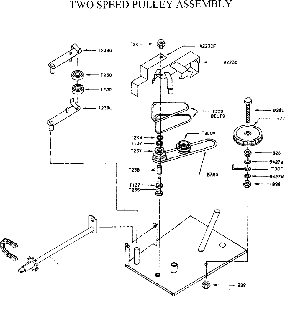
REPLACING TWO SPEED BELT:
Remove steering wheel throttle control knob and
engagement levers.
Remove hood (AZ154) and recoil shroud
Remove gas tank mounting bracket.
Remove belt cage (AZ32C).
Remove both two speed belts (T223).
Shift to low speed.
Lift fingers on Idler Arms (T239V and
T239L).
Slip belt under Idler Pulley and off of Drive
Pulleys.
Change to high speed.
Slip belt over Idler Pulley and off of Drive
Pulleys.
Remove Traction Belt (BA50), replace.
Reassemble all parts in reverse order.
Check all parts to make sure there is no interfer-
ence and that unit operates properly.
14
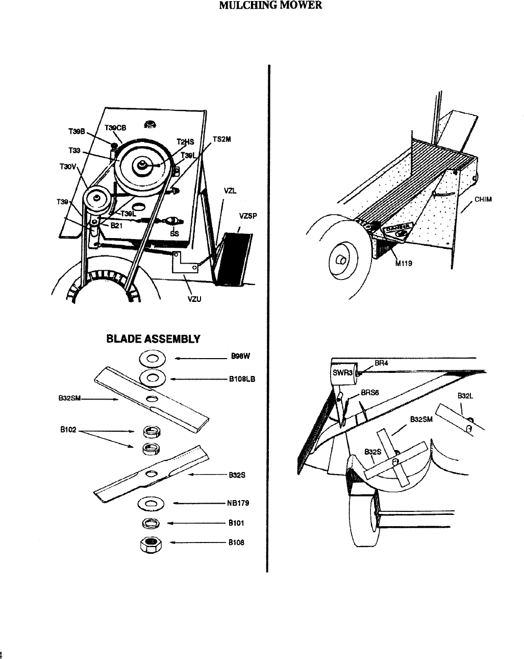
MULCHING MOWERS
(Models ending in M)
To adjust your mower for mulching, make sure your
discharge chute is closed so grass clippings cannot
escape and may be cut several times. To close the
chute, slide the chute TOWARD the mowing deck and
tighten the knob.
Your Swisher Mulching Mower has the built-in flex-
ibility to convert into a regular side discharge mower
within seconds. When grass has grown too tall for
mulching, you should use the side-discharge feature.
Change from Mulching Mower to Side
Discharge Feature:
WARNING! ALWAYS REMEMBER TO
TURN OFF YOUR ENGINE AND
BLADES BEFORE OPENING OR CLOS-
ING THE SIDE CHUTE!
Open the quick-change chute by unscrewing the
knob located on the right side of the mower deck.
(The chute is spring loaded and will open gently.)
After mowing with the chute open, close the chute
and make another pass over the grass clippings in
order to mulch them into fine clippings.
HINTS FOR EFFECTIVE MULCHING:
The key to effective mulching is to MOW OFTEN.
Grass which has grown abnormally long cannot be
mulched properly; attempting to mulch grass which
is too long will result with the grass clippings clump-
ing and leaving your lawn a mess.
It is important for the health of your lawn to insure
you do NOT cut your grass too short. Cutting the
grass less than one inch can weaken the grass and in-
creases the possibility of weeds and pests injuring your
lawn.
SWEEPER/COLLECTOR
MOWERS
(Models ending in S)
The Sweeper Mower can provide a manicured fin-
ish for your lawn if properly used. To obtain the
best results possible, you should consider the
height, type and condition of your grass and the
speed at which you mow. Remember, the sweeper
mechanism is automatically engaged any time the
blades are engaged.
MOWING HINTS - As with all collecting sys-
tems, your Sweeper will achieve maximum effi-
ciency if you do not allow the grass to grow too
high. Mowing regularly will not only enhance the
appearance of your lawn, but will reduce the num-
ber of times you need to empty the collector.
After the initial mowing with this mower, you may
notice areas of grass that appear to be cut unevenly.
As grass undergrowth usually grows outward in-
stead of upward, the Sweeper must lift the grass
blades before cutting. A second mowing of the
uneven areas should help the appearance. Regu-
lar mowing with your Sweeper Mower will help
prevent undergrowth from reestablishing; this will
encourage a thicker and healthier lawn.
STRIPING - You can achieve the same strip-
ing for your lawn with your Swisher Mower as
the professionals do on baseball fields or golf
courses. To do this, mow in a back and forth man-
ner - cutting in the opposite direction and directly
against the previously mowed path. The brushes
sweep the grass of alternate paths in opposite di-
rections.
POSITIONING AND REMOVING
COLLECTOR - When placing the collector on
the mower, lift the deflector covering to the rear
discharge opening of the mower and place the arms
of the collector securely into the respective slots.
The collector is easily removed for storage or for
mowing without the collector; simply lift the arms
of the collector simultaneously out of the slots.
Make certain the deflector shield covers the rear
discharge opening of the mower after removing
the bag.
15
EMPTYING THE COLLECTOR - BE SURE TO DIS-
ENGAGE BLADES AND STOP ENGINE BEFORE
EMPTYING THE COLLECTOR!
To empty the collector, pull the rear support bar of the
collector up toward the mower. The pile of clippings or
leaves will fall almost directly below the collector.
COMPOSTING
For those interested in composting their yard debris,
the easy-empty design of the bag will be of great ser-
vice. It allows you to gather your clippings in one
place without ever having to leave the drivers seat.
MULCHING - If your mower is not equipped with a
mulching attachment, you can still use your sweeper
to mulch. Simply empty the clippings into a pile, re-
cut the pile several times to get the reduced volume
desired. The valuable nutrients in these clippings can
either be returned to the soil by spreading the clip-
pings onto the lawn; you may also add the clippings
to your composter.
BRUSH ADJUSTMENTS
The sweeper brush has been cut at the factory to the most commonly used length. The length of brush, however,
may be easily shortened if necessary by following these procedures:
Turn the engine off and disconnect the spark plug wire.
Then take a sharp pair of scissors and cut the bristles to the desired length. Be sure and cut the same amount off
all three brushes, cutting completely across the length of the brush. We recommend not cutting more than 1/2
inch at a time to avoid cutting the bristles too short.
Check the performance of the Sweeper brush after each 1/2 inch trim
BAG AND BRUSH REPLACEMENT
The bag is subject to deterioration and wear during normal usage. Inspect the bag periodically for tears, holes or
weak spots. Replace as needed. Replacement bags and brooms are available from your local Swisher Mower
dealer or call the factory at 800-222-8183.

16
Swisher Zero Turn Rider
01 02 03 04
06
07
08
05
09
10
11
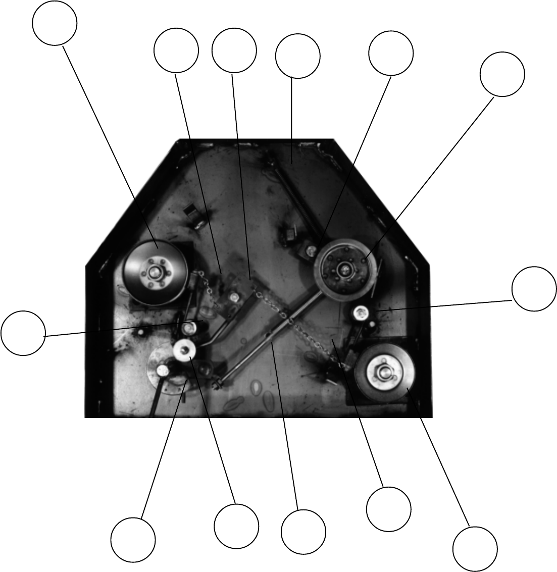
17
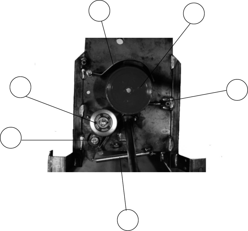
Belt housing with motor base removed
12 13 14 15 16 17
18
18
19
22 21 20
23
18
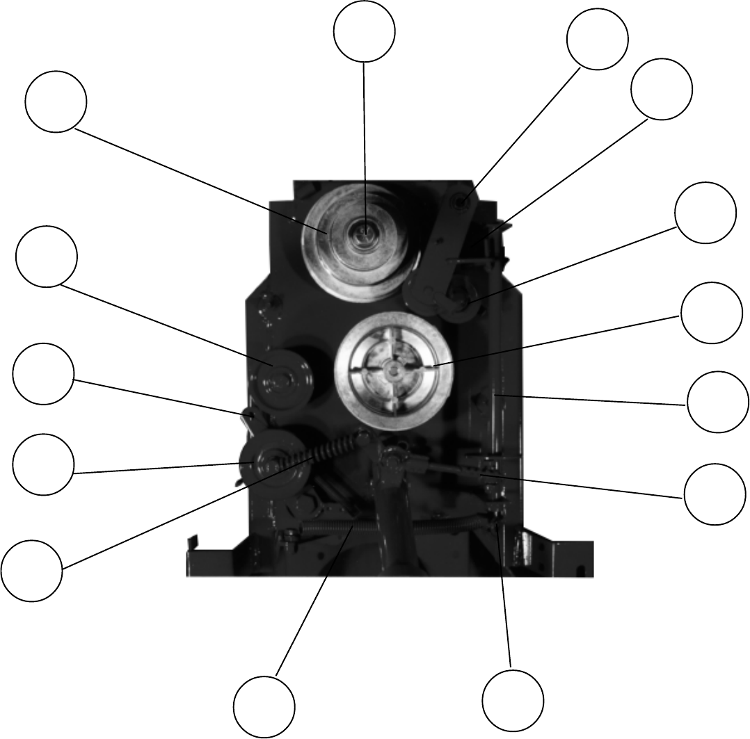
Two speed pulley assembly
37
24 25
26
27
28
29
30
31
32
33
34
36
35
19
41
40
38 39
43
42
Variable Speed Pulley Assembly
20
21
22
W
23
3002
Spring - TR193S
(Not Shown)
24
25
26
Replacement Parts
Hood AZ154
Grommet - large AZ154GL
Grommet - small AZ154GS
Hood trim AS116
Steering/fuel port trim AS117
Mounting bolt AZ154B
Acorn nuts FR154N
Gas cap AZ154C
Gas tank AZ154T
Tank mount AZ154TM
Tank straps AS013
Fuel line FLH27
Steering wheel AZ120
Bushing AZ120B
Set screw - short AZ120SS
Set screw - long AZ120SL
Key stock AZ120K
Bolt 1/4 - 20 x 1/2 AZ120BL
Cap plug AZ120CP
Steering shaft/sprocket AZ121
Seat AZ159
Seat hinge AZ159H
Seat plate AZ159P
Bolt/nut - seat AZ159PB
Bolt/nut - hinge AZ159HB
Seat spring A153
Seat safety switch SS97
Height adjust crank H7N
Rear tire/wheel/bearing F4157W
Cotter pin T218C
Rear axle HR156A
Rear axle weldment HR156
ITEM# DESCRIPTION PART
1
2
3
4
5
6
27
Replacement Parts
Lower shroud AZ154L
Washer/nut AZ154LWN
Front wheel/tire/bearing
Chain guard T162
Traction Assembly A124W
Flanged bushing (upper/lower) A124B
Steering gear pin A124P
Steering gear A124S
Gear case A136W
Flathead socket screws A140
Worm shaft T135
Gasket T136G
Gear case lid T136L
Bearing T137
Gear pin solid T138P
Roller bearing T139
Retainer ring T139S
Wheel bracket T140W
Split pin for sprocket T142P
Oil plug T143P
Chain idler T144
Thrust bearing T151
Washer T151W
Gear T152
Gear spacer T152S
Worm gear T153
Worm pin T153P
Gear lube TR124L
Bolt/nut TR136B
Gear shaft TR138
Seal TR138S
Kepnut 3/8” x 16 B21N
Master link 3/8” chain CL41
Shoulder bolt T139B
Sprocket T142
Belt release finger T30F
ITEM# DESCRIPTION PART
7
8
9
10
28
Replacement Parts
Idler control spring T30S
Idler spacer T30SL
Idler clutch pulley T30V
Idler clutch pulley bolt T31B
Engine belt T39
Top engine pulley TE32B
Idler control arm TR139AZ
Drive chain TR145
Air tire - 5 TR147W
Tube for TR147W TR147TW
Drive sprocket/hub assembly TR148W
Lock pin/lever & rivet TR148L
Lock pin - 5 Tire TR148PW
Lock pin spring TR148S
Front axle bolt/nut TR149W
Bearing TR150
Washer TR150W
Front wheel - 5 TR158W
Fender skirt - right AZ154FR
Fender skirt - left AZ154FL
Blade driver assembly - left see illustration #
Left brake chain BT35
Brake lever BT97AZ
Tension spring BRS6
Idler arm 678R
Bolt/nut B21
Idler pulley B527
Brake pad BP370
Brake spring BT297
Bolt/nut/washer BT297B, BT297N, BT297W
Blade driver assembly - right see illustration #
Right brake chain BT315
Idler rod/spring B25RAZ
Brake cam bearing BCB
ITEM# DESCRIPTION PART
11
12
13
14
15
16
17
18
19
20
21
22
29
Replacement Parts
Blade engage lever assembly BR20AZ
Three step pulley bolt/nut T23S/T2K
Upper idler arm T239U
Upper idler arm pulley T230
2 speed hi-lo link T22L
Lower idler arm T239L
Lower idler arm pulley T230
Two step pulley T2LUV
Shift rod T2AZ
Shift linkage T2AZL
Tension linkage TZ2F
Tension spring 682S
Belt engage spring T30S
Belt drive pulley T30V
Belt drive pulley arm TR139AZ
Idler pulley B27
Three step pulley T23V
Bearing spacer T23B
Belt release cage A223C
Belt release finger A223CF
Belt, High/Low - 23 T223
Bolt/nut for grass chute CH5B
Grass chute CH5
Grass chute clips CH5S
Shift lever AZ125L
Shift levers/knobs AZ125/B19
Shift tube assembly AZ125T
Variable speed brake T39CB
Drive pulley T33
Spring T2SM
Link T39L
Spring 682S
Idler arm V139AZ
Idler pulley T30V
23
24
25
26
27
28
29
30
31
32
33
34
35
36
37
38
39
40
41
42
43
ITEM# DESCRIPTION PART
Two Speed only
Two Speed items not shown
Variable Speed only
30
Replacement Parts
Accelerator lower linkage VZL
Accelerator pedal VZSP
Accelerator upper linkage VZU
Eye bolt for accelerator VZE
Mounting bolt/nut for pedal VZBN
Air filter (Briggs 8hp) FF8
Anti-scalp rollers SWR3
Anti-vibration rubber clamp A155V
Battery cable - black BCS
Battery cable - red BCSR
Battery cable (long) BCL
Battery cable, small rubber boot BCBT
Battery pad BATPAD
Battery, 12 volt BAT
Bearing, rear wheel F157B
Belt cover - left AZ155L
Belt cover - right AZ155R
Bolt for roller (sweeper) BR4
Bolt for Vari-Speed brake T39B
Bracket for height adjustment axle HR156C
Brake pad T39BP
Brake pad retainer spring BP370S
Brake spring spacer BT297S
Chute Baffle CHB
Chute baffle hinge pin CHBP
Clutch Rod Spring P682WS
Engine bolts & nuts EBN
Finger for idler pulley B427F
Floor mat FZ161
Foot pedal mat FZ161P
Fuel line hose clamp FLHC
Grommet for belt cover A155G
Heat shield AZHB12
In line fuel filter ILFF
Key switch KSM
Key switch - 12 volt KS12
ITEM# DESCRIPTION PART
Variable Speed items not shown
All Models items not shown
31
Replacement Parts
Keys KSK
Knob for mulching chute M119
Lower engine pulley (Briggs) BB105
Rear axle weldment HR156
Safety switch SS
Solenoid SOL NEW
Spacer for engine pulley BB105S
Thick Washer for axle A156TW
Throttle cable assembly THRAZ
Washer for Axle A156W
Washer, hardened steel T2KW
Wire link for idler arm BRS6H
Arrow Hi-Low D54
Big Mow D53
Blade engage/disengage D10
Caution Hands D20
Caution No Step D11
Caution Oil Level D14
Clutch Lever D18
Danger Spinning Blade D29
Key Switch D28
Made in Missouri D31
Mulch or Discharge D27
Ride King D52
Serial Number D17
Step Decal D24
Swisher (hood decal) D51
Swisher (rear decal) D50
Warning Serious Injury D45
Warning Triangle D55
ITEM# DESCRIPTION PART
Decals
32
Replacement Parts
Blade Assembly
Blade spacer 1/4 B101
Blade spacer 1/2 B102
Blade spacer 1 B103
Blade pulley, left B104
Washer B104W
Blade nut B108
Belleville lock washer (2/set) B108LB
Blade set B32
Blade, 18 B32L
Blade set - mulching B32M
Blade, 14 B32S
Blade, 12 - mulcher B32SM
Blade bearing B98
Washer B98W
Housing for blade & shaft B99C
Bolt for B99C B99CB
Blade belt BA50
Blade pulley, right BZ104
ITEM# DESCRIPTION PART

LIMITED WARRANTY
The manufacturers warranty to the original consumer purchaser is: This product is free from
defects in materials and workmanship, for a period of one (1) year from the date of purchase by the
original consumer purchaser. We will repair or replace, at our discretion, parts found to be defective
due to materials or workmanship. This warranty is subject to the following limitations and exclu-
sions:
1) Engine Warranty All engines utilized on our products have a separate warranty
extended to them by the individual engine manufacturer. Any
engine service difficulty is the responsibility of the engine
manufacturer, and in no way is Swisher Mower Co., Inc. or
its agents responsible for the engine warranty. The Briggs &
Stratton Engine Service Hot-Line is 1-800-233-3723. The
Tecumseh Engine Service Hot-Line is 1-800-558-5402.
2) Commercial Use The warranty period for any product used for commercial or
rental is limited to ninety (90) days from the date of original
purchase.
3) Limitations This warranty applies only to products which have been
properly assembled, adjusted, and operated in accordance with
the instructions contained within this manual. This warranty
does not apply to any product of Swisher Mower Co., Inc.,
that has been subject to alteration, misuse, abuse, improper
assembly or installation, shipping damage, or to normal wear
of the product.
4) Exclusions Excluded from this warranty are normal wear, normal
adjustments, and normal maintenance.
In the event you have a claim under this warranty, you must return the product to an authorized
service dealer. All transportation charges, and damage and loss incurred during transportation of
parts submitted for replacement or repair under this warranty shall be borne by the purchaser. Should
you have any questions concerning this warranty, please contact us toll-free 1-800-748-7108.
THIS WARRANTY DOES NOT APPLY TO ANY INCIDENTAL OR CONSEQUENTIAL
DAMAGES AND ANY IMPLIED WARRANTIES ARE LIMITED TO THE SAME TIME
PERIODS STATED HEREIN FOR ALL EXPRESSED WARRANTIES. Some states do not allow
the limitation of consequential damages or limitations on how long an implied warranty may last, so
the above limitations or exclusions may not apply to you. This warranty gives you specific legal
rights, and you may have other rights, which vary from state-to-state. This is a limited warranty as
defined by the Magnuson-Moss Act of 1975.

PRINTED IN U.S.A.
Zero Turn
Riding Mowers
OWNER’S
MANUAL
MODEL NO.
All AZ Series
SWISHER MOWER & MACHINE CO. INC.
TELEPHONE - 1-800-222-8183
FAX - 1-660-747-8650
SWISHER MOWER & MACHINE CO. INC.
P.O. BOX 67
WARRENSBURG, MO 64093
Each mower has its own model number. Each engine has its own
model number. The model number for the mower will be
found on the right hand side of the drive belt housing. The
model number for the engine will be found on the top of the
blower fan housing.
All mower parts listed herein may be ordered directly from
Swisher Mower & Machine Co. Inc. or your nearest Swisher
dealer.
All engine parts may be ordered from the nearest dealer of the
engine supplied with your mower.
WHEN ORDERING PARTS, PLEASE HAVE THE
FOLLOWING INFORMATION AVAILABLE.
* PRODUCT - AZ RIDER
* SERIAL NUMBER - ________________
* MODEL NUMBER - ________________
* ENGINE MODEL NUMBER - ________________
TYPE - ________________
* PART NUMBER
* PART DESCRIPTION
