Symbol Technologies AP5181D Symbol Access Point User Manual ES3000UserGuide
Symbol Technologies Inc Symbol Access Point ES3000UserGuide
UserManual.wiki
>
Symbol Technologies
>
AP5181D User Manual
>
Manual Part 3 3
Contents
1.
Manual Part 1
2.
Manual Part 2
3.
Manual Part 3 1
4.
Manual Part 3 2
5.
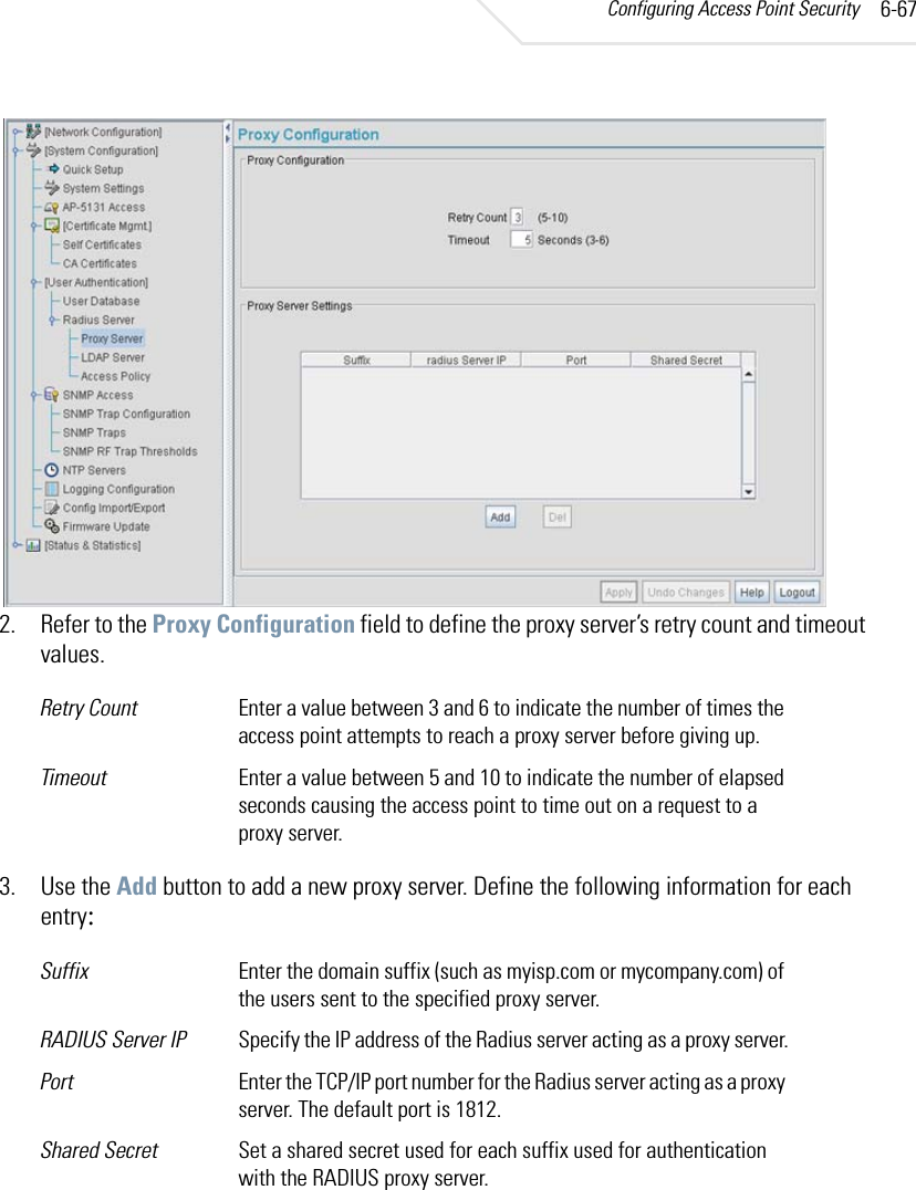
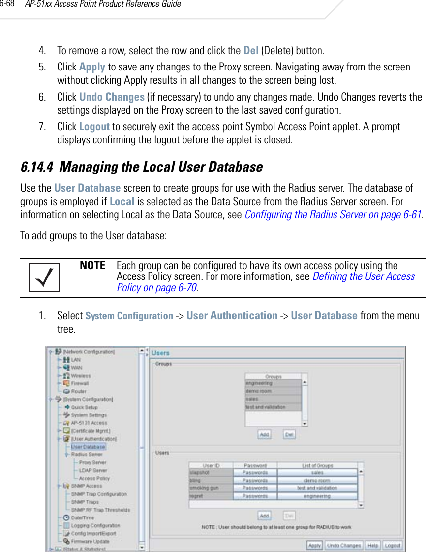
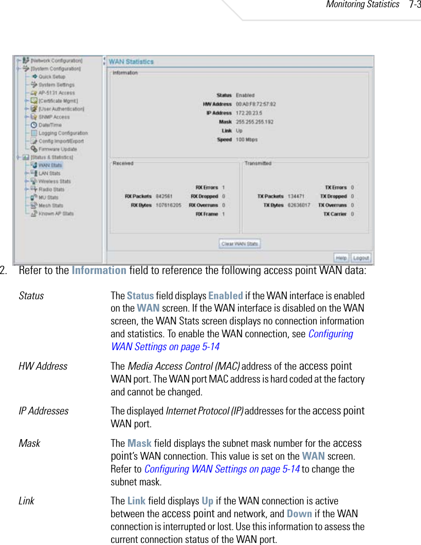
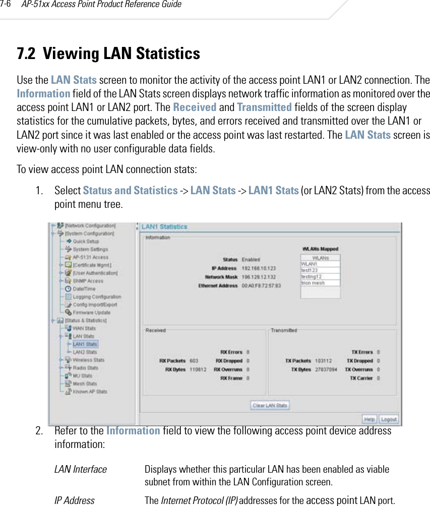
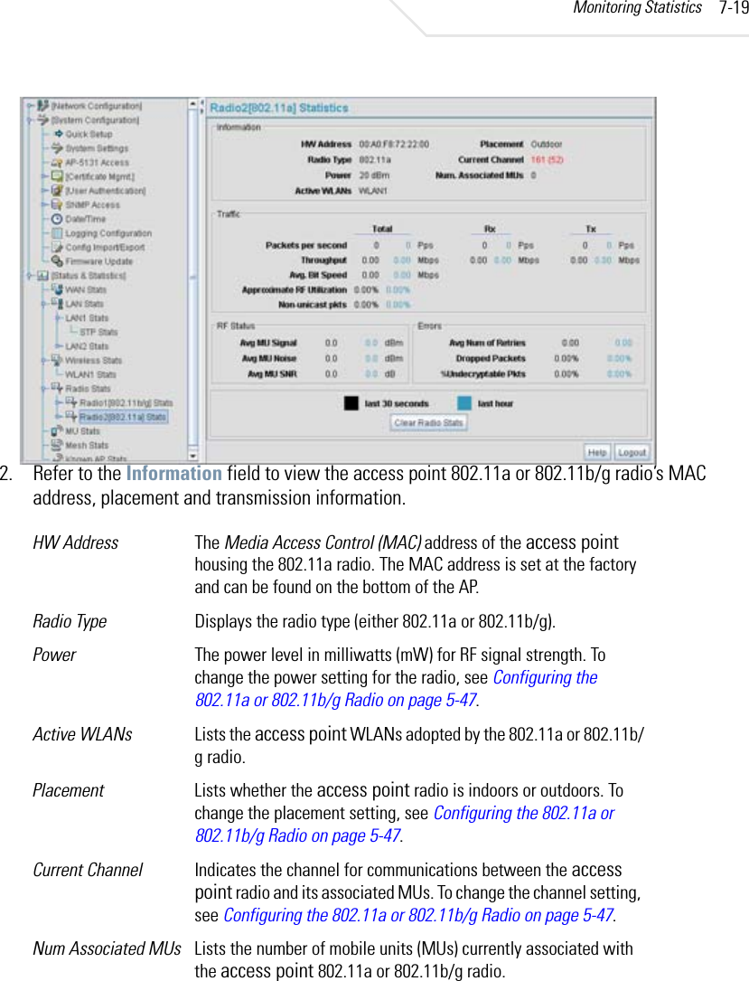
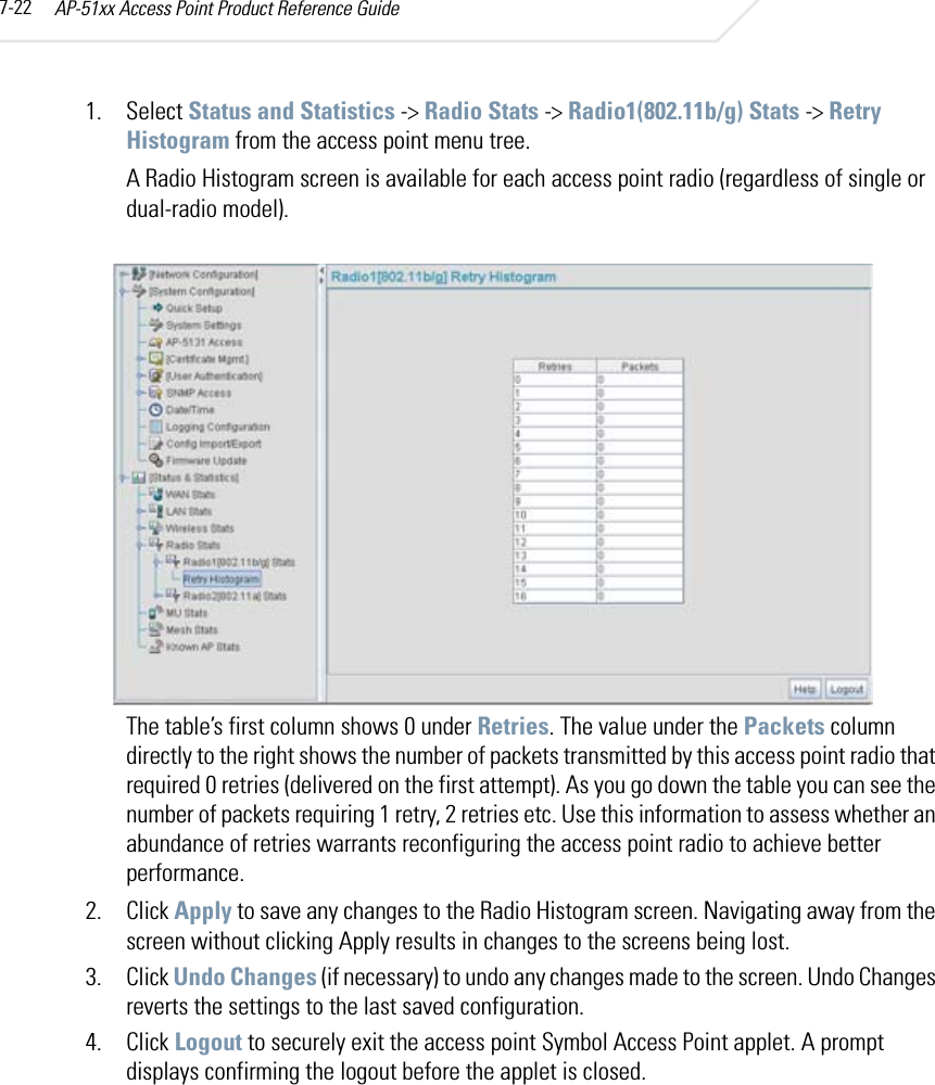
Manual Part 3 3
6.
Manual Part 3 4
Manual Part 3 3
Navigation menu
Upload a User Manual
Namespaces
Wiki Guide
HTML
PDF
Info
Views
User Manual
Discussion / Help
Navigation