Symbol Technologies AP5181D Symbol Access Point User Manual ES3000UserGuide
Symbol Technologies Inc Symbol Access Point ES3000UserGuide
Contents
Manual Part 3 4

Command Line Interface Reference 8-5
AP51xx>admin>passwd
Description:
Changes the password for the admin login.
Syntax:
Example:
admin>passwd
Old Admin Password:******
New Admin Password:******
Verify Admin Password:******
Password successfully updated
For information on configuring passwords using the applet (GUI), see Setting Passwords on page 6-3.
passwd Changes the admin password for access point access. This requires typing the old admin password and entering a
new password and confirming it. Passwords can be up to 11 characters. The access point CLI treats the following as
invalid characters:
| " & , \ ' < >
In order to avoid problems when using the access point CLI, these characters should be avoided.

AP-51xx Access Point Product Reference Guide8-6
AP51xx>admin>summary
Description:
Displays the access point’s system summary.
Syntax:
Example:
admin>summary
AP-51xx firmware version 1.1.0.0-xxx
country code us
serial number 00A0F8716A74
WLAN 1:
WLAN Name WLAN1
ESS ID 101
Radio 11a, 11b/g
VLAN VLAN1
Security Ploicy Default
QoS Ploicy Default
LAN1 Name: LAN1
LAN1 Mode: enable
LAN1 IP: 0.0.0.0
LAN1 Mask: 0.0.0.0
LAN1 Mask: client
LAN2 Name: LAN2
LAN2 Mode: enable
LAN2 IP: 192.235.1.1
LAN2 Mask: 255.255.255.0
LAN2 Mask: client
-----------------------------------------------------------------------------
WAN Interface IP Address Network Mask Default Gateway DHCP Client
-----------------------------------------------------------------------------
enable 172.20.23.10 255.255.255.192 172.20.23.20 enable
For information on displaying a system summary using the applet (GUI), see Basic Device Configuration on page 3-3.
summary Displays a summary of high-level characteristics and settings for the WAN, LAN and WLAN.

Command Line Interface Reference 8-7
AP51xx>admin>..
Description:
Displays the parent menu of the current menu.
This command appears in all of the submenus under admin. In each case, it has the same function, to move up one level in the
directory structure.
Example:
admin(network.lan)>..
admin(network)>

AP-51xx Access Point Product Reference Guide8-8
AP51xx>admin> /
Description:
Displays the root menu, that is, the top-level CLI menu.
This command appears in all of the submenus under admin. In each case, it has the same function, to move up to the top level in the
directory structure.
Example:
admin(network.lan)>/
admin>

Command Line Interface Reference 8-9
AP51xx>admin>save
Description:
Saves the configuration to system flash.
The save command appears in all of the submenus under admin. In each case, it has the same function, to save the current
configuration.
Syntax:
Example:
admin>save
admin>
save Saves configuration settings. The save command works at all levels of the CLI. The save command must be issued before
leaving the CLI for updated settings to be retained.

AP-51xx Access Point Product Reference Guide8-10
AP51xx>admin>quit
Description:
Exits the command line interface session and terminates the session.
The quit command appears in all of the submenus under admin. In each case, it has the same function, to exit out of the CLI. Once
the quit command is executed, the login prompt displays again.
Example:
admin>quit

Command Line Interface Reference 8-11
8.3 Network Commands
AP51xx>admin(network)>
Description:
Displays the network submenu. The items available under this command are shown below.
lan Goes to the LAN submenu.
wan Goes to the WAN submenu.
wireless Goes to the Wireless Configuration submenu.
firewall Goes to the firewall submenu.
router Goes to the router submenu.
.. Goes to the parent menu.
/Goes to the root menu.
save Saves the current configuration to the system flash.
quit Quits the CLI and exits the current session.

AP-51xx Access Point Product Reference Guide8-12
8.3.1 Network LAN Commands
AP51xx>admin(network.lan)>
Description:
Displays the LAN submenu. The items available under this command are shown below.
For an overview of the LAN configuration options using the applet (GUI), see Configuring the LAN Interface on page 5-1.
show Shows current access point LAN parameters.
set Sets LAN parameters.
bridge Goes to the mesh configuration submenu.
wlan-mapping Goes to the WLAN/Lan/Vlan Mapping submenu.
dhcp Goes to the LAN DHCP submenu.
type-filter Goes to the Ethernet Type Filter submenu.
.. Goes to the parent menu.
/Goes to the root menu.
save Saves the configuration to system flash.
quit Quits the CLI.

Command Line Interface Reference 8-13
AP51xx>admin(network.lan)> show
Description:
Displays the access point LAN settings.
Syntax:
Example:
admin(network.lan)>show
LAN On Ethernet Port : LAN1
LAN Ethernet Timeout : disable
802.1x Port Authentication:
Username : admin
Password : ********
** LAN1 Information **
LAN Name : LAN1
LAN Interface : enable
802.11q Trunking : disable
LAN IP mode : DHCP client
IP Address : 192.168.0.1
Network Mask : 255.255.255.255
Default Gateway : 192.168.0.1
Domain Name :
Primary DNS Server : 192.168.0.1
Secondary DNS Server : 192.168.0.2
WINS Server : 192.168.0.254
** LAN2 Information **
LAN Name : LAN2
LAN Interface : disable
802.11q Trunking : disable
LAN IP mode : DHCP server
IP Address : 192.168.1.1
Network Mask : 255.255.255.255
Default Gateway : 192.168.1.1
Domain Name :
show Shows the settings for the access point LAN1 and LAN2 interfaces.

AP-51xx Access Point Product Reference Guide8-14
Primary DNS Server : 192.168.0.2
Secondary DNS Server : 192.168.0.3
WINS Server : 192.168.0.255
admin(network.lan)>
For information on displaying LAN information using the applet (GUI), see Configuring the LAN Interface on page 5-1.

Command Line Interface Reference 8-15
AP51xx>admin(network.lan)> set
Description:
Sets the LAN parameters for the LAN port.
Syntax:
Example:
admin(network.lan)>
admin(network.lan)>set lan 1 enable
admin(network.lan)>set name 1 engineering
admin(network.lan)>set ethernet-port-lan 1
admin(network.lan)>set timeout 45
admin(network.lan)>set trunking 1 disable
admin(network.lan)>set dns 1 192.168.0.1
admin(network.lan)>set dns 2 192.168.0.2
admin(network.lan)>set wins 1 192.168.0.254
admin(network.lan)>set trunking disable
admin(network.lan)>set username phil
admin(network.lan)>set passwd ea0258c1
Related Commands:
For information on configuring the LAN using the applet (GUI), see Configuring the LAN Interface on page 5-1.
set lan <mode> Enables or disables the access point LAN interface.
name <idx-name > Defines the LAN name by index.
ethernet-port-lan <idx> Defines which LAN (LAN 1 or LAN 2) is active on the Ethernet port.
timeout <seconds> Sets the interval (in seconds) the access point uses to terminate its LAN
interface if no activity is detected for the specified interval.
trunking <mode> Enables or disables 802.11q Trunking over the access point LAN port.
username <name> Specifies the user name for 802.1x port authentication over the LAN
interface.
passwd <password> The 0-32 character password for the username for the 802.1x port.
ip-mode <ip> Defines the access point LAN port IP mode.
ipadr <ip> Sets the IP address used by the LAN port.
mask <ip> Defines the IP address used for access point LAN port network mask.
dgw <ip> Sets the Gateway IP address used by the LAN port.
domain <name> Specifies the domain name used by the access point LAN port.
dns <ip> Defines the IP address of the primary and secondary DNS servers used by the
LAN port.
wins <ip> Defines the IP address of the WINS server used by the LAN port.
show Shows the current settings for the access point LAN port.

AP-51xx Access Point Product Reference Guide8-16
8.3.1.1 Network LAN, Bridge Commands
AP51xx>admin(network.lan.bridge)>
Description:
Displays the access point Bridge submenu.
For an overview of the access point’s mesh networking options using the applet (GUI), see Configuring Mesh Networking on page 9-1.
show Displays the mesh configuration parameters for the access point’s LANs.
set Sets the mesh configuration parameters for the access point’s LANs..
.. Moves to the parent menu.
/Goes to the root menu.
save Saves the configuration to system flash.
quit Quits the CLI and exits the session.

Command Line Interface Reference 8-17
AP51xx>admin(network.lan.bridge)> show
Description:
Displays the mesh bridge configuration parameters for the access point’s LANs.
Syntax:
Example:
admin(network.lan.bridge)>show
** LAN1 Bridge Configuration **
Bridge Priority :32768
Hello Time (seconds) :2
Message Age Time (seconds) :20
Forward Delay Time (seconds) :15
Entry Ageout Time (seconds) :300
** LAN2 Bridge Configuration **
Bridge Priority :32768
Hello Time (seconds) :2
Message Age Time (seconds) :20
Forward Delay Time (seconds) :15
Entry Ageout Time (seconds) :300
For an overview of the access point’s mesh networking options using the applet (GUI), see Configuring Mesh Networking on page 9-1.
show Displays the mesh bridge
configuration parameters for the access point’s LANs.

AP-51xx Access Point Product Reference Guide8-18
AP51xx>admin(network.lan.bridge)> set
Description:
Sets the mesh configuration parameters for the access point’s LANs.
Syntax:
Example:
admin(network.lan.bridge)>set priority 2 32768
admin(network.lan.bridge)>set hello 2 2
admin(network.lan.bridge)>set msgage 2 20
admin(network.lan.bridge)>set fwddelay 2 15
admin(network.lan.bridge)>set ageout 2 300
admin(network.lan.bridge)>show
** LAN1 Mesh Configuration **
Bridge Priority :32768
Hello Time (seconds) :2
Message Age Time (seconds) :20
Forward Delay Time (seconds) :15
Entry Ageout Time (seconds) :300
** LAN2 Mesh Configuration **
Bridge Priority :32768
Hello Time (seconds) :2
Message Age Time (seconds) :20
Forward Delay Time (seconds) :15
Entry Ageout Time (seconds) :300
For an overview of the access point’s mesh networking options using the applet (GUI), see Configuring Mesh Networking on page 9-1.
set priority <LAN-idx> <seconds> Sets bridge priority time in seconds (0-65535) for specified LAN.
hello <LAN-idx> <seconds> Sets bridge hello time in seconds (0-10) for specified LAN.
msgage <LAN-idx> <seconds> Sets bridge message age time in seconds (6-40) for specified LAN.
fwddelay <LAN-idx> <seconds> Sets bridge forward delay time in seconds (4-30) for specified LAN.
ageout <LAN-idx> <seconds> Sets bridge forward table entry time in seconds (4-3600) for specified LAN.

Command Line Interface Reference 8-19
8.3.1.2 Network LAN, WLAN-Mapping Commands
AP51xx>admin(network.lan.wlan-mapping)>
Description:
Displays the WLAN/Lan/Vlan Mapping submenu.
For an overview of the access point’s VLAN configuration options using the applet (GUI), see Configuring VLAN Support on page 5-4.
show Displays the VLAN list currently defined for the access point.
set Sets the access point VLAN configuration.
create Creates a new access point VLAN.
edit Edits the properties of an existing access point VLAN.
delete Deletes a VLAN.
lan-map Maps access point existing WLANs to an enabled LAN.
vlan-map Maps access point existing WLANs to VLANs.
.. Moves to the parent menu.
/Goes to the root menu.
save Saves the configuration to system flash.
quit Quits the CLI and exits the session.

AP-51xx Access Point Product Reference Guide8-20
AP51xx>admin(network.lan.wlan-mapping)> show
Description:
Displays the VLAN list currently defined for the access point.. These parameters are defined with the set command.
Syntax:
Example:
admin(network.lan.wlan-mapping)>show name
-----------------------------------------------------------------------------
Index VLAN ID VLAN Name
-----------------------------------------------------------------------------
1 1 VLAN_1
2 2 VLAN_2
3 3 VLAN_3
4 4 VLAN_4
admin(network.lan.wlan-mapping)>show vlan-cfg
Management VLAN Tag :1
Native VLAN Tag :2
WLAN :WLAN1
mapped to VLAN :VLAN 2
VLAN Mode :static
admin(network.lan.wlan-mapping)>show lan-wlan
WLANs on LAN1:
:WLAN1
:WLAN2
:WLAN3
WLANs on LAN2:
show name Displays the existing list of VLAN names.
vlan-cfg Shows WLAN-VLAN mapping and VLAN configuration.
lan-wlan Displays a WLAN-LAN mapping summary.
wlan Displays the WLAN summary list.

Command Line Interface Reference 8-21
admin(network.lan.wlan-mapping)>show wlan
WLAN1:
WLAN Name :WLAN1
ESSID :101
Radio :
VLAN :
Security Policy :Default
QoS Policy :Default
For information on displaying the VLAN screens using the applet (GUI), see Configuring VLAN Support on page 5-4.

AP-51xx Access Point Product Reference Guide8-22
AP51xx>admin(network.lan.wlan-mapping)> set
Description:
Sets VLAN parameters for the access point.
Syntax:
Example:
admin(network.lan.wlan-mapping)>set mgmt-tag 1
admin(network.lan.wlan-mapping)>set native-tag 2
admin(network.lan.wlan-mapping)>set mode 1 static
admin(network.lan.wlan-mapping)>show vlan-cfg
Management VLAN Tag :1
Native VLAN Tag :2
WLAN :WLAN1
mapped to VLAN :VLAN 2
VLAN Mode :static
For information on configuring VLANs using the applet (GUI), see Configuring VLAN Support on page 5-4.
set mgmt- tag <id> Defines the Management VLAN tag (1-4095).
native-tag <id> Sets the Native VLAN tag (1-4095).
mode <wlan-idx> Sets WLAN VLAN mode (WLAN 1-16) to either dynamic or static.

Command Line Interface Reference 8-23
AP51xx>admin(network.lan.wlan-mapping)> create
Description:
Creates a VLAN for the access point.
Syntax:
Example:
admin(network.lan.wlan-mapping)>
admin(network.lan.wlan-mapping)>create 5 vlan-5
For information on creating VLANs using the applet (GUI), see Configuring VLAN Support on page 5-4.
create vlan-id <id> Defines the VLAN ID (1-4095).
vlan-name <name> Specifies the name of the VLAN (1-31 characters in length).

AP-51xx Access Point Product Reference Guide8-24
AP51xx>admin(network.lan.wlan-mapping)> edit
Description:
Modifies a VLAN’s name and ID.
Syntax:
For information on editing VLANs using the applet (GUI), see Configuring VLAN Support on page 5-4.
edit name <name> Modifies an exisiting VLAN name (1-31 characters in length)
id <id> Modifies an existing VLAN ID (1-4095) characters in length).

Command Line Interface Reference 8-25
AP51xx>admin(network.lan.wlan-mapping)> delete
Description:
Deletes a specific VLAN or all VLANs.
Syntax:
For information on deleting VLANs using the applet (GUI), see Configuring VLAN Support on page 5-4.
delete < VLAN id> Deletes a specific VLAN ID (1-16).
all Deletes all defined VLANs.

AP-51xx Access Point Product Reference Guide8-26
AP51xx>admin(network.lan.wlan-mapping)> lan-map
Description:
Maps an access point VLAN to a WLAN.
Syntax: ..
admin(network.lan.wlan-mapping)>lan-map wlan1 lan1
For information on mapping VLANs using the applet (GUI), see Configuring VLAN Support on page 5-4.
lan-map <wlan name> <lan name> Maps an existing WLAN to an enabled LAN. All names and IDs are case-sensitive.

Command Line Interface Reference 8-27
AP51xx>admin(network.lan.wlan-mapping)> vlan-map
Description:
Maps an access point VLAN to a WLAN.
Syntax:
admin(network.lan.wlan-mapping)>vlan-map wlan1 vlan1
For information on mapping VLANs using the applet (GUI), see Configuring VLAN Support on page 5-4.
vlan-map <wlan name> <vlan name> Maps an existing WLAN to an enabled LAN. All names and IDs are case-sensitive.

AP-51xx Access Point Product Reference Guide8-28
8.3.1.3 Network LAN, DHCP Commands
AP51xx>admin(network.lan.dhcp)>
Description:
Displays the access point DHCP submenu. The items available are displayed below.
show Displays DHCP parameters.
set Sets DHCP parameters.
add Adds static DHCP address assignments.
delete Deletes static DHCP address assignments.
list Lists static DHCP address assignments.
.. Goes to the parent menu.
/Goes to the root menu.
save Saves the configuration to system flash.
quit Quits the CLI and exits the session.

Command Line Interface Reference 8-29
AP51xx>admin(network.lan.dhcp)> show
Description:
Shows DHCP parameter settings.
Syntax:
Example:
admin(network.lan.dhcp)>show
**LAN1 DHCP Information**
DHCP Address Assignment Range:
Starting IP Address : 192.168.0.100
Ending IP Address : 192.168.0.254
Lease Time : 86400
**LAN2 DHCP Information**
DHCP Address Assignment Range:
Starting IP Address : 192.168.0.100
Ending IP Address : 192.168.0.254
Lease Time : 86400
For information on configuring DHCP using the applet (GUI), see Configuring the LAN Interface on page 5-1.
show Displays DHCP parameter settings for the access point. These parameters are defined with the set
command.

AP-51xx Access Point Product Reference Guide8-30
AP51xx>admin(network.lan.dhcp)> set
Description:
Sets DHCP parameters for the LAN port.
Syntax:
Example:
admin(network.lan.dhcp)>set range 1 192.168.0.100 192.168.0.254
admin(network.lan.dhcp)>set lease 1 86400
admin(network.lan.dhcp)>show
**LAN1 DHCP Information**
DHCP Address Assignment Range:
Starting IP Address : 192.168.0.100
Ending IP Address : 192.168.0.254
Lease Time : 86400
For information on configuring DHCP using the applet (GUI), see Configuring the LAN Interface on page 5-1.
set range <LAN-idx> <ip1> <ip2> Sets the DHCP assignment range from IP address <ip1> to IP address <ip2> for the
specified LAN.
lease <LAN-idx> <lease> Sets the DHCP lease time <lease> in seconds (1-999999) for the specified LAN.

Command Line Interface Reference 8-31
AP51xx>admin(network.lan.dhcp)> add
Description:
Adds static DHCP address assignments.
Syntax:
Example:
admin(network.lan.dhcp)>add 1 00A0F8112233 192.160.24.6
admin(network.lan.dhcp)>add 1 00A0F1112234 192.169.24.7
admin(network.lan.dhcp)>list 1
-----------------------------------------------------------------------------
Index MAC Address IP Address
-----------------------------------------------------------------------------
1 00A0F8112233 192.160.24.6
2 00A0F8112234 192.169.24.7
For information on adding client MAC and IP address information using the applet (GUI), see Configuring Advanced DHCP Server
Settings on page 5-11.
add <LAN-idx> <mac> <ip> Adds a reserved static IP address to a MAC address for the specified LAN.

AP-51xx Access Point Product Reference Guide8-32
AP51xx>admin(network.lan.dhcp)> delete
Description:
Deletes static DHCP address assignments.
Syntax:
Example:
admin(network.lan.dhcp)>list 1
-----------------------------------------------------------------------------
Index MAC Address IP Address
-----------------------------------------------------------------------------
1 00A0F8112233 10.1.2.4
2 00A0F8102030 10.10.1.2
3 00A0F8112234 10.1.2.3
4 00A0F8112235 192.160.24.6
5 00A0F8112236 192.169.24.7
admin(network.lan.dhcp)>delete 1
-----------------------------------------------------------------------------
index mac address ip address
-----------------------------------------------------------------------------
1 00A0F8102030 10.10.1.2
2 00A0F8112234 10.1.2.3
3 00A0F8112235 192.160.24.6
4 00A0F8112236 192.169.24.7
admin(network.lan.dhcp)>delete 1 all
-----------------------------------------------------------------------------
index mac address ip address
-----------------------------------------------------------------------------
For information on deleting client MAC and IP address information using the applet (GUI), see
Configuring Advanced DHCP Server Settings on page 5-11.
delete <LAN-idx> <entry> Deletes the static DHCP address entry for the specified LAN.
<LAN-idx> all Deletes all static DHCP addresses.

Command Line Interface Reference 8-33
AP51xx>admin(network.lan.dhcp)> list
Description:
Lists static DHCP address assignments.
Syntax:
Example:
admin(network.lan.dhcp)>list 1
-----------------------------------------------------------------------------
Index MAC Address IP Address
-----------------------------------------------------------------------------
1 00A0F8112233 10.1.2.4
2 00A0F8102030 10.10.1.2
3 00A0F8112234 10.1.2.3
4 00A0F8112235 192.160.24.6
5 00A0F8112236 192.169.24.7
admin(network.lan.dhcp)>
For information on listing client MAC and IP address information using the applet (GUI), see Configuring Advanced DHCP Server
Settings on page 5-11.
list <LAN-idx> Lists the static DHCP address assignments for the specified LAN.

AP-51xx Access Point Product Reference Guide8-34
8.3.1.4 Network Type Filter Commands
AP51xx>admin(network.lan.type-filter)>
Description:
Displays the access point Type Filter submenu. The items available under this command include:
e
show Displays the current Ethernet Type exception list.
set Defines Ethernet Type Filter parameters.
add Adds an Ethernet Type Filter entry.
delete Removes an Ethernet Type Filter entry.
.. Goes to the parent menu.
/Goes to the root menu.
save Saves the configuration to system flash.
quit Quits the CLI.

Command Line Interface Reference 8-35
AP51xx>admin(network.lan.type-filter)> show
Description:
Displays the access point’s current Ethernet Type Filter configuration.
Syntax:
Example:
admin(network.lan.type-filter)>show 1
Ethernet Type Filter mode : allow
-----------------------------------------------------------------------------
index ethernet type
-----------------------------------------------------------------------------
1 8137
For information on displaying the type filter configuration using the applet (GUI), see Setting the Type Filter Configuration on page 5-
13.
show <LAN-idx> Displays the existing Type-Filter configuration for the specified LAN.

AP-51xx Access Point Product Reference Guide8-36
AP51xx>admin(network.lan.type-filter)> set
Description:
Defines the access point Ethernet Type Filter configuration.
Syntax:
Example:
admin(network.lan.type-filter)>set mode 1 allow
For information on configuring the type filter settings using the applet (GUI), see Setting the Type Filter Configuration on page 5-13.
set mode <LAN-idx> allow or deny Allows or denies the access point from processing a specified Ethernet
data type for the specified LAN.

Command Line Interface Reference 8-37
AP51xx>admin(network.lan.type-filter)> add
Description:
Adds an Ethernet Type Filter entry.
Syntax:
Example:
admin(network.lan.type-filter)>
admin(network.wireless.type-filter)>add 1 8137
admin(network.wireless.type-filter)>add 2 0806
admin(network.wireless.type-filter)>show 1
Ethernet Type Filter mode : allow
-----------------------------------------------------------------------------
index ethernet type
-----------------------------------------------------------------------------
1 8137
2 0806
3 0800
4 8782
For information on configuring the type filter settings using the applet (GUI), see Setting the Type Filter Configuration on page 5-13.
add <LAN-idx> <type> Adds entered Ethernet Type to list of data types either allowed or denied access point
processing permissions for the specified LAN.

AP-51xx Access Point Product Reference Guide8-38
AP51xx>admin(network.lan.type-filter)> delete
Description:
Removes an Ethernet Type Filter entry individually or the entire Type Filter list.
Syntax:
Example:
admin(network.lan.type-filter)>delete 1 1
admin(network.lan.type-filter)>show 1
Ethernet Type Filter mode : allow
-----------------------------------------------------------------------------
index ethernet type
-----------------------------------------------------------------------------
1 0806
2 0800
3 8782
admin(network.lan.type-filter)>delete 2 all
admin(network.lan.type-filter)>show 2
Ethernet Type Filter mode : allow
-----------------------------------------------------------------------------
index ethernet type
-----------------------------------------------------------------------------
For information on configuring the type filter settings using the applet (GUI), see Setting the Type Filter Configuration on page 5-13.
delete <LAN-idx> <index> Deletes the specified Ethernet Type index entry (1 through 16).
<LAN-idx> all Deletes all Ethernet Type entries currently in list.

Command Line Interface Reference 8-39
8.3.2 Network WAN Commands
AP51xx>admin(network.wan)>
Description:
Displays the WAN submenu. The items available under this command are shown below.
For an overview of the WAN configuration options using the applet (GUI), see Configuring WAN Settings on page 5-14.
show Displays the access point WAN configuration and the access point’s current PPPoE configuration.
set Defines the access point’s WAN and PPPoE configuration.
nat Displays the NAT submenu, wherein Network Address Translations (NAT) can be defined.
vpn Goes to the VPN submenu, where the access point VPN tunnel configuration can be set.
content Displays the Outbound Content Filtering submenu, where data types can be included/excluded from access point
throughput.
.. Goes to the parent menu.
/Goes to the root menu.
save Saves the current configuration to the access point system flash.
quit Quits the CLI and exits the current session.

AP-51xx Access Point Product Reference Guide8-40
AP51xx>admin(network.wan)> show
Description:
Displays the access point WAN port parameters.
Syntax:
Example:
admin(network.wan)>show
Status : enable
WAN DHCP Client Mode : disable
IP address : 0.0.0.0
Network Mask : 0.0.0.0
Default Gateway : 10.10.1.1
Primary DNS Server : 0.0.0.0
Secondary DNS Server : 0.0.0.0
WAN IP 2 : disable
WAN IP 3 : disable
WAN IP 4 : disable
WAN IP 5 : disable
WAN IP 6 : disable
WAN IP 7 : disable
WAN IP 8 : disable
PPPoE Mode : enable
PPPoE User Name : JohnDoe
PPPoE Password : *******
PPPoE keepalive mode : enable
PPPoE Idle Time : 600
PPPoE Authentication Type : chap
PPPoE State
admin(network.wan)>
For an overview of the WAN configuration options available using the applet (GUI), see
Configuring WAN Settings on page 5-14.
show Shows the general IP parameters for the WAN port along with settings for the WAN interface..

Command Line Interface Reference 8-41
AP51xx>admin(network.wan)> set
Description:
Defines the configuration of the access point WAN port.
Syntax:
Example:
admin(network.wan)>
admin(network.wan)>set dhcp disable
admin(network.wan)>set ipadr 157.169.22.5
admin(network.wan)>set dgw 157.169.22.1
admin(network.wan)>set dns 1 157.169.22.2
admin(network.wan)>set mask 255.255.255.000
admin(network.wan)>set pppoe mode enable
admin(network.wan)>set pppoe type chap
admin(network.wan)>set pppoe user jk
admin(network.wan)>set pppoe passwd @#$goodpassword%$#
admin(network.wan)>set pppoe ka enable
admin(network.wan)>set pppoe idle 600
For an overview of the WAN configuration options available using the applet (GUI), see Configuring WAN Settings on page 5-14.
set wan enable/disable Enables or disables the access point WAN port.
dhcp enable/disable Enables or disables WAN DHCP Client mode.
ipadr <idx> <a.b.c.d> Sets up to 8 (using <indx> from 1 to 8) IP addresses <a.b.c.d> for the
access point WAN interface.
mask <a.b.c.d> Sets the subnet mask for the access point WAN interface.
dgw <a.b.c.d> Sets the default gateway IP address to <a.b.c.d>.
dns <idx> <a.b.c.d> Sets the IP address of one or two DNS servers, where <indx> indicates
either the primary (1) or secondary (2) server, and <a.b.c.d> is the IP
address of the server.
pppoe mode enable/disable Enables or disables PPPoE.
user <name> Sets PPPoE user name.
passwd <password> Defines the PPPoE password.
ka enable/disable Enables or disables PPPoE keepalive.
idle <time> Sets PPPoE idle time.
type <auth-type> Sets PPPoE authentication type.

AP-51xx Access Point Product Reference Guide8-42
8.3.2.1 Network WAN NAT Commands
AP51xx>admin(network.wan.nat)>
Description:
Displays the NAT submenu. The items available under this command are shown below.
For an overview of the NAT configuration options available using the applet (GUI), see
Configuring Network Address Translation (NAT) Settings on page 5-19.
show Displays the access point’s current NAT parameters for the specified index.
set Defines the access point NAT settings.
add Adds NAT entries.
delete Deletes NAT entries.
list Lists NAT entries.
.. Goes to the parent menu.
/Goes to the root menu.
save Saves the configuration to system flash.
quit Quits the CLI.

Command Line Interface Reference 8-43
AP51xx>admin(network.wan.nat)> show
Description:
Displays access point NAT parameters.
Syntax:
Example:
admin(network.wan.nat)>show 2
WAN IP Mode : disable
WAN IP Address : 157.235.91.2
NAT Type : 1-to-many
One to many nat mapping : LAN1 LAN2
Inbound Mappings : Port Forwarding
unspecified port forwarding mode : enable
unspecified port fwd. ip address : 111.223.222.1
admin(network.wan.nat)>
For an overview of the NAT options available using the applet (GUI), see
Configuring Network Address Translation (NAT) Settings on page 5-19.
show <idx> Displays access point NAT parameters for the specified NAT index.

AP-51xx Access Point Product Reference Guide8-44
AP51xx>admin(network.wan.nat)> set
Description:
Sets NAT inbound and outbound parameters.
Syntax:
Example:
admin(network.wan.nat)>set type 1-to-many
admin(network.wan.nat)>set ip 157.235.91.2
admin(network.wan.nat)>set mode 2 disable
admin(network.wan.nat)>set unspec-ip 2 111.223.222.1
admin(network.wan.nat)>show 2
WAN IP Mode : disable
WAN IP Address : 157.235.91.2
NAT Type : 1-to-many
One to many nat mapping : LAN1 LAN2
Inbound Mappings : Port Forwarding
unspecified port forwarding mode : enable
unspecified port fwd. ip address : 111.223.222.1
For an overview of the NAT options available using the applet (GUI), see Configuring Network Address Translation (NAT) Settings on
page 5-19.
set type <index> <type> Sets the type of NAT translation for WAN address index <idx> (1-8) to
<type> (none, 1-to-1, or 1-to-many).
ip <index> <ip> Sets NAT IP mapping associated with WAN address <idx> to the
specified IP address <ip>.
inb enable/disable <ip> Sets inbound NAT parameters.
outb <ip> <map> Sets outbound NAT parameters.
mode <index> enable/disable Enable or disable the Unspecified Port Forwarding mode for the
designated NAT index.
unspec-ip <index> <ip> Forward unspecified ports for the defined NAT index to the defined IP
address.

Command Line Interface Reference 8-45
AP51xx>admin(network.wan.nat)> add
Description:
Adds NAT entries.
Syntax:
Example:
admin(network.wan.nat)>add 1 indoors udp 20 29 10.10.2.2
admin(network.wan.nat)>list 1
-----------------------------------------------------------------------------
index name prot start port end port internal ip translation port
-----------------------------------------------------------------------------
1 indoor udp 20 29 10.10.2.2 0
Related Commands:
For an overview of the NAT options available using the applet (GUI), see
Configuring Network Address Translation (NAT) Settings on page 5-19.
add <idx> <name> <tran> <port1> <port2> <ip> <dst_port>
Sets an inbound network address translation (NAT) for WAN address <idx>, where <name> is the name of the entry
(1 to 7 characters), <tran> is the transport protocol (one of tcp, udp, icmp, ah, esp, gre, or all), <port1> is the starting
port number in a port range, <port2> is the ending port number in a port range, <ip> is the internal IP address, and
<dst_port> is the (optional) internal translation port.
delete Deletes one of the inbound NAT entries from the list.
list Displays the list of inbound NAT entries.

AP-51xx Access Point Product Reference Guide8-46
AP51xx>admin(network.wan.nat)> delete
Description:
Deletes NAT entries.
Syntax:
Example:
admin(network.wan.nat)>list 1
-----------------------------------------------------------------------------
index name prot start port end port internal ip translation port
-----------------------------------------------------------------------------
1 special tcp 20 21 192.168.42.16 21
admin(network.wan.nat)>delete 1 1
^
admin(network.wan.nat)>list 1
-----------------------------------------------------------------------------
index name prot start port end port internal ip translation port
-----------------------------------------------------------------------------
Related Commands:
For an overview of the NAT options available using the applet (GUI), see
Configuring Network Address Translation (NAT) Settings on page 5-19.
delete <idx> <entry> Deletes a specified NAT index entry <entry> associated with the WAN.
<idx> all Deletes all NAT entries associated with the WAN.
add Adds entries to the list of inbound NAT entries.
list Displays the list of inbound NAT entries.

Command Line Interface Reference 8-47
AP51xx>admin(network.wan.nat)> list
Description:
Lists access point NAT entries for the specified index.
Syntax:
Example:
admin(network.wan.nat)>list 1
-----------------------------------------------------------------------------
index name Transport start port end port internal ip translation
port
-----------------------------------------------------------------------------
1 special tcp 20 21 192.168.42.16 21
Related Commands:
1
For an overview of the NAT options available using the applet (GUI), see Configuring Network Address Translation (NAT) Settings on
page 5-19.
list <idx> Lists the inbound NAT entries associated with WAN port.
delete Deletes inbound NAT entries from the list.
add Adds entries to the list of inbound NAT entries.

AP-51xx Access Point Product Reference Guide8-48
8.3.2.2 Network WAN, VPN Commands
AP51xx>admin(network.wan.vpn)>
Description:
Displays the VPN submenu. The items available under this command include:
For an overview of the VPN options available using the applet (GUI), see Configuring VPN Tunnels on page 6-33.
add Adds VPN tunnel entries.
set Sets key exchange parameters.
delete Deletes VPN tunnel entries.
list Lists VPN tunnel entries
reset Resets all VPN tunnels.
stats Lists security association status for the VPN tunnels.
ikestate Displays an Internet Key Exchange (IKE) summary.
.. Goes to the parent menu.
/Goes to the root menu.
save Saves the configuration to system flash.
quit Quits the CLI.

Command Line Interface Reference 8-49
AP51xx>admin(network.wan.vpn)> add
Description:
Adds a VPN tunnel entry.
Syntax:
Example:
admin(network.wan.vpn)>add 2 SJSharkey 209.235.44.31 206.107.22.46
255.255.255.224 206.107.22.1
If tunnel type is Manual, proper SPI values and Keys must be configured after
adding the tunnel
admin(network.wan.vpn)>
For information on configuring VPN using the applet (GUI), see Configuring VPN Tunnels on page 6-33.
add <name> <LAN idx> <LWanIP> <RSubnetIP> <RSubnetMask <RGatewayIP>
Creates a tunnel <name> (1 to 13 characters) to gain access through local WAN IP <LWanIP> from the remote subnet
with address <RSubnetIP> and subnet mask <RSubnetMask> using the remote gateway <RGatewayIP>.

AP-51xx Access Point Product Reference Guide8-50
AP51xx>admin(network.wan.vpn)> set
Description:
Sets VPN entry parameters.
Syntax:
set type <name> <tunnel type> Sets the tunnel type <name> to Auto or Manual
for the specified tunnel name.
authalgo <name> <authalgo> Sets the authentication algorithm for <name> to
(None, MD5, or SHA1).
authkey <name> <dir> <authkey> Sets the AH authentication key (if type is
Manual) for tunnel <name> with the direction set
to IN or OUT, and the manual authentication key
set to <authkey>. (The key size is 32 hex characters
for MD5, and 40 hex characters for SHA1).
esp-type <name> <esptype> Sets the Encapsulating Security Payload (ESP)
type. Options include None, ESP, or ESP-AUTH.
esp-encalgo <name> <escalgo> Sets the ESP encryption algorithm. Options include
DES, 3DES, AES128, AES192, or AES256).
esp-enckey <name> <dir> <enckey> Sets the Manual Encryption Key in ASCII for tunnel
<name> and direction IN or OUT to the key <enc-
key>. The size of the key depends on the
encryption algorithm.
- 16 hex characters for DES
- 48 hex characters for 3DES
- 32 hex characters for AES128
- 48 hex characters for AES192
- 64 hex characters for AES256
esp-authalgo <name> <authalgo> Sets the ESP authentication algorithm. Options
include MD5 or SHA1.
esp-authkey <name> <dir> <authkey> Sets ESP Authentication key <name> either for IN
or OUT direction to <auth-key>, an ASCII string of
hex characters. If authalgo is set to MD5, then
provide 32 hex characters. If authalgo is set to
SHA1, provide 40 hex characters.
spi <name> <algo> <dir> <value> Sets 6 character IN(bound) or OUT(bound) for
AUTH (Manual Authentication) or ESP for
<name> to <spi> (a hex value more than 0xFF)
<value>.
usepfs <name> <mode> Enables or disables Perfect Forward Secrecy for
<name>.

Command Line Interface Reference 8-51
For information on configuring VPN using the applet (GUI), see Configuring VPN Tunnels on page 6-33.
salife <name> <lifetime> Defines the name of the tunnnel <name> the
Security Association Life Time <300-65535>
applies to in seconds.
ike opmode <name> <opmode> Sets the Operation Mode of IKE for <name> to
Main or Aggr(essive).
myidtype <name> <idtype> Sets the Local ID type for IKE authentication for
<name> (1 to 13 characters) to <idtype> (IP, FQDN,
or UFQDN).
remidtype <name> <idtype> Sets the Remote ID type for IKE authentication for
<name> (1 to 13 characters) to <idtype> (IP, FQDN,
or UFQDN).
myiddata <name> <idtype> Sets the Local ID data for IKE authentication for
<name> to <idtype>. This value is not required
when the ID type is set to IP.
remiddata <name> <idtype> Sets the Local ID data for IKE authentication for
<name> to <idtype>. This value is not required
when the ID type is set to IP.
authtype <name> <authtype> Sets the IKE Authentication type for <name> to
<authtype> ( PSK or RSA).
authalgo <name> <authalgo> Sets the IKE Authentication Algorithm for <name>
to MD5 or SHA1.
phrase <name> <phrase> Sets the IKE Authentication passphrase for
<name> to <phrase>.
encalgo <name> <encalgo> Sets the IKE Encryption Algorithm for <name> to
<encalgo> (one of DES, 3DES, AES128, AES192,
or AES256).
lifetime <name> <lifetime> Sets the IKE Key life time in seconds for <name> to
<lifetime>.
group <name> <group> Sets the IKE Diffie-Hellman Group for <name> to
either G768 or G1024.

AP-51xx Access Point Product Reference Guide8-52
AP51xx>admin(network.wan.vpn)> delete
Description:
Deletes VPN tunnel entries.
Syntax:
Example:
admin(network.wan.vpn)>list
--------------------------------------------------------------------------
Tunnel Name Type Remote IP/Mask Remote Gateway Local WAN IP
--------------------------------------------------------------------------
Eng2EngAnnex Manual 192.168.32.2/24 192.168.33.1 192.168.24.198
SJSharkey Manual 206.107.22.45/27 206.107.22.2 209.235.12.55
admin(network.wan.vpn)>delete Eng2EngAnnex
admin(network.wan.vpn)>list
--------------------------------------------------------------------------
Tunnel Name Type Remote IP/Mask Remote Gateway Local WAN IP
--------------------------------------------------------------------------
SJSharkey Manual 206.107.22.45/27 206.107.22.2 209.235.12.55
admin(network.wan.vpn)>
For information on configuring VPN using the applet (GUI), see Configuring VPN Tunnels on page 6-33.
delete all Deletes all VPN entries.
<name> Deletes VPN entries <name>.

Command Line Interface Reference 8-53
AP51xx>admin(network.wan.vpn)> list
Description:
Lists VPN tunnel entries.
Syntax:
Example:
admin(network.wan.vpn)>list
--------------------------------------------------------------------------
Tunnel Name Type Remote IP/Mask Remote Gateway Local WAN IP
--------------------------------------------------------------------------
Eng2EngAnnex Manual 192.168.32.2/24 192.168.33.1 192.168.24.198
SJSharkey Manual 206.107.22.45/27 206.107.22.2 209.235.12.55
admin(network.wan.vpn)>list SJSharkey
--------------------------------------------------------------------------
Detail listing of VPN entry:
--------------------------------------------------------------------------
Name : SJSharkey
Local Subnet : 1
Tunnel Type : Manual
Remote IP : 206.107.22.45
Remote IP Mask : 255.255.255.224
Remote Security Gateway : 206.107.22.2
Local Security Gateway : 209.239.160.55
AH Algorithm : None
Encryption Type : ESP
Encryption Algorithm : DES
ESP Inbound SPI : 0x00000100
ESP Outbound SPI : 0x00000100
For information on displaying VPN information using the applet (GUI), see Viewing VPN Status on page 6-47.
list <cr> Lists all tunnel entries.
<name> Lists detailed information about tunnel named <name>. Note that the <name> must match case with the name of
the VPN tunnel entry

AP-51xx Access Point Product Reference Guide8-54
AP51xx>admin(network.wan.vpn)> reset
Description:
Resets all of the access point’s VPN tunnels.
Syntax:
Example:
admin(network.wan.vpn)>reset
VPN tunnels reset.
admin(network.wan.vpn)>
For information on configuring VPN using the applet (GUI), see Configuring VPN Tunnels on page 6-33.
reset Resets all VPN tunnels.

Command Line Interface Reference 8-55
AP51xx>admin(network.wan.vpn)> stats
Description:
Lists statistics for all active tunnels.
Syntax:
Example:
admin(network.wan.vpn)>stats
-----------------------------------------------------------------------------
Tunnel Name Status SPI(OUT/IN) Life Time Bytes(Tx/Rx)
-----------------------------------------------------------------------------
Eng2EngAnnex Not Active
SJSharkey Not Active
For information on displaying VPN information using the applet (GUI), see Viewing VPN Status on page 6-47.
stats Display statistics for all VPN tunnels.

AP-51xx Access Point Product Reference Guide8-56
AP51xx>admin(network.wan.vpn)> ikestate
Description:
Displays statistics for all active tunnels using Internet Key Exchange (IKE).
Syntax:
Example:
admin(network.wan.vpn)>ikestate
----------------------------------------------------------------------
Tunnel Name IKE State Dest IP Remaining Life
----------------------------------------------------------------------
Eng2EngAnnex Not Connected ---- ---
SJSharkey Not Connected ---- ---
admin(network.wan.vpn)>
For information on configuring IKE using the applet (GUI), see Configuring IKE Key Settings on page 6-43.
ikestate Displays status about Internet Key Exchange (IKE) for all tunnels. In particular, the table indicates whether IKE is
connected for any of the tunnels, it provides the destination IP address, and the remaining lifetime of the IKE key.

Command Line Interface Reference 8-57
8.3.3 Network Wireless Commands
AP51xx>admin(network.wireless)
Description:
Displays the access point wireless submenu. The items available under this command include:
wlan Displays the WLAN submenu used to create and configure up to 16 WLANs per access point.
security Displays the security submenu used to create encryption and authentication based security policies for use with
access point WLANs.
acl Displays to the Access Control List (ACL) submenu to restrict or allow MU access to access point WLANs.
radio Displays the radio configuration submenu used to specify how the 802.11a or 802.11b/g radio is used with
specific WLANs.
qos Displays the Quality of Service (QoS) submenu to prioritize specific kinds of data traffic within a WLAN.
bandwidth Displays the Bandwidth Management submenu used to configure the order data is processed by an access point radio.
rogue-ap Displays the Rogue-AP submenu to configure devices located by the access point as friendly or threatening for
interoperablity.
.. Goes to the parent menu.
/Goes to the root menu.
save Saves the configuration to system flash.
quit Quits the CLI.

AP-51xx Access Point Product Reference Guide8-58
8.3.3.1 Network WLAN Commands
AP51xx>admin(network.wireless.wlan)>
Description:
Displays the access point wireless LAN (WLAN) submenu. The items available under this command include:
e
For an overview of the Wireless configuration options available to the using the applet (GUI), see Enabling Wireless LANs (WLANs)
on page 5-22.
show Displays the access point’s current WLAN configuration.
create Defines the parameters of a new WLAN.
edit Modifies the properties of an existing WLAN.
delete Deletes an existing WLAN.
hotspot Displays the WLAN hotspot menu.
.. Goes to the parent menu.
/Goes to the root menu.
save Saves the configuration to system flash.
quit Quits the CLI.

Command Line Interface Reference 8-59
AP51xx>admin(network.wireless.wlan)> show
Description:
Displays the access point’s current WLAN configuration.
Syntax:
Example:
admin(network.wireless.wlan)>show summary
WLAN1
WLAN Name : Lobby
ESSID : 101
Radio : 11a, 11b/g
VLAN :
Security Policy : Default
QoS Policy : Default
admin(network.wireless.wlan)>show wlan 1
ESS Identifier : 101
WLAN Name : Lobby
802.11a Radio : available
802.11b/g Radio : not available
Client Bridge Mesh Backhaul : available
Hotspot : not available
Maximum MUs : 127
Security Policy : Default
MU Access Control : Default
Kerberos User Name : 101
Kerberos Password : ********
Disallow MU to MU Communication : disable
Use Secure Beacon : disable
Accept Broadcast ESSID : disable
QoS Policy : Default
For information on displaying WLAN infromation using the applet (GUI), see Enabling Wireless LANs (WLANs) on page 5-22.
show summary Displays the current configuration for existing WLANs.
wlan <number> Displays the configuration for the requested WLAN (WLAN 1 through 16).

AP-51xx Access Point Product Reference Guide8-60
AP51xx>admin(network.wireless.wlan)> create
Description:
Defines the parameters of a new WLAN.
Syntax:
sh
Example:
admin(network.wireless.wlan.create)>show wlan
ESS Identifier :
WLAN Name :
802.11a Radio : available
802.11b/g Radio : not available
Client Bridge Mesh Backhaul : not available
Hotspot : not available
Maximum MUs : 127
Security Policy : Default
MU Access Control :
Kerberos User Name : Default
Kerberos Password : ********
Disallow MU to MU Communication : disable
Use Secure Beacon : disable
create
show wlan <number> Displays newly created WLAN and policy number.
set ess <essid> Defines the ESSID for a target WLAN.
wlan-name <name> Determines the name of this particlular WLAN (1-32).
11a <mode> Enables or disables access to the access point 802.11a radio.
11bg <mode> Enables or disables access to the access point 802.11b/g radio.
mesh <mode> Enables or disables the Client Bridge Mesh Backhaul option.
hotspot <mode> Enables or disables the Hotspot mode.
max-mu <number> Defines the maximum number of MU able to operate within the WLAN
(default = 127 MUs).
security <name> Sets the security policy to the WLAN (1-32).
acl <name> Sets the MU ACL policy to the WLAN (1-32).
passwd <ascii string> Defines a Kerberos password used if the WLAN’s security policy uses a
Kerberos server-based authentication scheme.
no-mu-mu <mode> Enables or disables MUs associated to the same WLAN to not
communicate with each other.
sbeacon <mode> Enables or disables the AP-51xx from transmitting the ESSID in the
beacon.
bcast <mode> Enables or disables the access point from accepting broadcast IDs from
MUs. Broadcast IDs are transmitted without security.
qos <name> Defines the index name representing the QoS policy used with this
WLAN.
add-wlan Apply the changes to the modified WLAN and exit.
.. Disregard the changes to the modified WLAN and exit.

Command Line Interface Reference 8-61
Accept Broadcast ESSID : disable
QoS Policy : Default
admin(network.wireless.wlan.create)>show security
----------------------------------------------------------------------
Secu Policy Name Authen Encryption Associated WLANs
----------------------------------------------------------------------
1 Default Manual no encrypt Front Lobby
2 WEP Demo Manual WEP 64 2nd Floor
3 Open Manual no encrypt 1st Floor
admin(network.wireless.wlan.create)>show acl
----------------------------------------------------------------------
ACL Policy Name Associated WLANs
----------------------------------------------------------------------
1 Default Front Lobby
2 Admin 3rd Floor
3 Demo Room 5th Floor
admin(network.wireless.wlan.create)>show qos
----------------------------------------------------------------------
QOS Policy Name Associated WLANs
----------------------------------------------------------------------
1 Default Front Lobby
2 Voice Audio Dept
3 Video Video Dept
For information on creating a WLAN using the applet (GUI), see Creating/Editing Individual WLANs on page 5-24.

AP-51xx Access Point Product Reference Guide8-62
AP51xx>admin(network.wireless.wlan)> edit
Description:
Edits the properties of an existing WLAN policy.
Syntax:
For information on editing a WLAN using the applet (GUI), see Creating/Editing Individual WLANs on page 5-24.
edit <index> Edits the properties of an existing WLAN policy.
show Displays the WLANs pamaters and summary.
set Edits the same WLAN parameters that can be modified using the create command.
change Completes the WLAN edits and exits the CLI session.
.. Cancel the WLAN edits and exit the CLI session.

Command Line Interface Reference 8-63
AP51xx>admin(network.wireless.wlan)> delete
Description:
Deletes an existing WLAN.
Syntax:
For information on deleting a WLAN using the applet (GUI), see Creating/Editing Individual WLANs on page 5-24.
delete <wlan-name> Deletes a target WLAN by name supplied.
all Deletes all WLANs defined.

AP-51xx Access Point Product Reference Guide8-64
AP51xx>admin(network.wireless.wlan.hotspot)>
Description:
Displays the Hotspot submenu. The items available under this command include:
e
For information on configuring the Hotspot options available to the using the applet (GUI), see
Configuring WLAN Hotspot Support on page 5-39.
show Show hotspot parameters.
redirection Goes to the hotspot redirection menu.
radius Goes to the hotspot Radius menu.
white-list Goes to the hotspot white-list menu.
save Saves the configuration to system flash.
quit Quits the CLI.
.. Goes to the parent menu.
/Goes to the root menu.

Command Line Interface Reference 8-65
AP51xx>admin(network.wireless.wlan.hotspot)> show
Description:
Displays the current access point Rogue AP detection configuration.
Syntax:
Example:
admin(network.wireless.wlan.hotspot)>show hotspot 1
WLAN1
Hotspot Mode : enable
Hotspot Page Location : default
External Login URL : www.sjsharkey.com
External Welcome URL :
External Fail URL :
Primary Server Ip adr :157.235.21.21
Primary Server Port :1812
Primary Server Secret :******
Secondary Server Ip adr :157.235.32.12
Secondary Server Port :1812
Secondary Server Secret :******
Accounting Mode :disable
Accounting Server Ip adr :0.0.0.0
Accounting Server Port :1813
Accounting Server Secret :********
Accoutning Timeout :10
Accoutning Retry-count :3
Whitelist Rules?
-----------------------------------------------------------------------------
Idx IP Address
-----------------------------------------------------------------------------
1 157.235.121.12
For information on configuring the Hotspot options available to the access point using the applet (GUI), see
Configuring WLAN Hotspot Support on page 5-39.
show hotspot <idx> Shows hotspot parameters per wlan index (1-16).

AP-51xx Access Point Product Reference Guide8-66
AP51xx>admin(network.wireless.wlan.hotspot)> redirection
Description:
Goes to the hotspot redirection menu.
Syntax:
Example:
admin(network.wireless.wlan.hotspot)>set page-loc 1 www.sjsharkey.com
admin(network.wireless.wlan.hotspot)>set exturl 1 fail www.sjsharkey.com
For information on configuring the Hotspot options available to the access point using the applet (GUI), see
Configuring WLAN Hotspot Support on page 5-39.
redirection set <page-loc> Sets the hotspot http-re-direction by index (1-16) for the specified URL.
<exturl> Shows hotspot http-redirection details for specifiec index (1-16) for specified
page (login, welcome, fail) and target URL..
show Shows hotspot http-redirection details.
save Saves the updated hotspot configuration to flash memory.
quit Quits the CLI session.
.. Goes to the parent menu.
/Goes to the root menu.

Command Line Interface Reference 8-67
AP51xx>admin(network.wireless.wlan.hotspot)> radius
Description:
Goes to the hotspot Radius menu.
Syntax:
For information on configuring the Hotspot options available to the access point using the applet (GUI), see
Configuring WLAN Hotspot Support on page 5-39.
set Sets the Radius hotspot configuration.
show Shows Radius hotspot server details.
save Saves the configuration to system flash.
quit Quits the CLI.
.. Goes to the parent menu.
/Goes to the root menu.

AP-51xx Access Point Product Reference Guide8-68
AP51xx>admin(network.wireless.wlan.hotspot.radius)> set
Description:
Sets the Radius hotspot configuration.
Syntax:
Example:
admin(network.wireless.wlan.hotspot.radius)>set server 1 primary 157.235.121.1
admin(network.wireless.wlan.hotspot.radius)>set port 1 primary 1812
admin(network.wireless.wlan.hotspot.radius)>set secret 1 primary sjsharkey
admin(network.wireless.wlan.hotspot.radius)>set acct-mode 1 enable
admin(network.wireless.wlan.hotspot.radius)>set acct-server 1 157.235.14.14
admin(network.wireless.wlan.hotspot.radius)>set acct-port 1 1812
admin(network.wireless.wlan.hotspot.radius)>set acct-secret londonfog
admin(network.wireless.wlan.hotspot.radius)>set acct-timeout 1 25
admin(network.wireless.wlan.hotspot.radius)>set acct-retry 1 10
For information on configuring the Hotspot options available to the access ointusing the applet (GUI), see
Configuring WLAN Hotspot Support on page 5-39.
set server <idx> <srvr_type> <ipadr> Sets the Radius hotpost server IP address per wlan index (1-16)
port <idx> <srvr_type> <port> Sets the Radius hotpost server port per wlan index (1-16)
secret <idx> <srvr_type> <secret> Sets the Radius hotspot server shared secret password.
acct-mode <idx> <mode> Sets the Radius hotspot server accounting mode
(enable/disable)
acct-server <idx> <ipadr> Sets the Radius hotspot accounting server IP address per wlan
index (1-16).
acct-port <idx> <port> Sets the Radius hotspot accounting server port per wlan index
(1-16).
acct-secret <idx> <secret> Sets the Radius hotspot server shared secret password per wlan
index (1-16).
acct-timeout <idx> <timeout> Sets the Radius hotspot server accounting timeout period in
seconds (1-25).
acct-retry <idx> <retry_count> Sets the Radius hotspot server accounting accounting retry
interval (1-10).

Command Line Interface Reference 8-69
AP51xx>admin(network.wireless.wlan.hotspot.radius)> show
Description:
Shows Radius hotspot server details.
Syntax:
Example:
admin(network.wireless.wlan.hotspot.radius)>show radius 1
Primary Server Ip adr : 157.235.12.12
Primary Server Port : 1812
Primary Server Secret : ******
Secondary Server Ip adr : 0.0.0.0
Secondary Server Port : 1812
Primary Server Secret : ******
Accounting Mode : enable
Accounting Server Ip adr : 157.235.15.16
Accounting Server Port : 1812
Accounting Server Secret : ******
Accounting Timeout : 10
Accounting Retry-count : 3
For information on configuring the Hotspot options available to the access point using the applet (GUI), see
Configuring WLAN Hotspot Support on page 5-39.
show radius <idx> Displays Radius hotspot server details per index (1-16)

AP-51xx Access Point Product Reference Guide8-70
AP51xx>admin(network.wireless.wlan.hotspot)> white-list
Description:
Goes to the hotspot white-list menu.
Syntax:
Example:
admin(network.wireless.wlan.hotspot.whitelist)>add rule 1 157.235.21.21
admin(network.wireless.wlan.hotspot.whitelist)>show white-rule 1
--------------------------------------------------------------------------------
Idx IP Address
--------------------------------------------------------------------------------
1 157.235.21.21
For information on configuring the Hotspot options available to the access point using the applet (GUI), see
Configuring WLAN Hotspot Support on page 5-39.
white-list add <rule> Adds hotspot whitelist rules by index (1-16) for specified IP address.
clear Clears hotspot whitelist rules for specified index (1-16).
show Shows hotspot whitelist rules for specified index (1-16).
save Saves the updated hotspot configuration to flash memory.
quit Quits the CLI session.
.. Goes to the parent menu.
/Goes to the root menu.

Command Line Interface Reference 8-71
8.3.3.2 Network Security Commands
AP51xx>admin(network.wireless.security)>
Description:
Displays the access point wireless security submenu. The items available under this command include:
For information the security configuration options available to the access point using the applet (GUI), see Configuring Security
Options on page 6-2.
show Displays the access point’s current security configuration.
create Defines the parameters of a security policy.
edit Edits the properties of an existing security policy.
delete Removes a specific security policy.
.. Goes to the parent menu.
/Goes to the root menu.
save Saves the configuration to system flash.
quit Quits the CLI.

AP-51xx Access Point Product Reference Guide8-72
AP51xx>admin(network.wireless.security)> show
Description:
Displays the access point’s current security configuration.
Syntax:
Example:
admin(network.wireless.security)>show summary
----------------------------------------------------------------------
Secu Policy Name Authen Encryption Associated WLANs
----------------------------------------------------------------------
1 Default Manual no encrypt Lobby
2 WEP Demo Manual WEP 64 2nd Floor
3 Open Manual no encrypt 1st Floor
admin(network.wireless.security)>show policy 1
Policy Name : Default
Authentication : Manual Pre-shared key/No Authentication
Encryption type : no encryption
Related Commands:
For information displaying existing WLAN security settings using the applet (GUI), see
Enabling Authentication and Encryption Schemes on page 6-5.
show summary Displays list of existing security policies (1-16).
policy <id> Displays the specified security policy <id>.
create Defines security parameters for the specified WLAN.

Command Line Interface Reference 8-73
AP51xx>admin(network.wireless.security)> create
Description:
Defines the parameter of access point security policies.

AP-51xx Access Point Product Reference Guide8-74
Syntax:
create Defines the parameters of a security policy.
show Displays new or existing security policy
parameters.
set sec-name <name> Sets the name of the security policy.
auth <authtype> Sets the authentication type for WLAN <idx> to
<type> (none, eap, or kerberos).
Note: Kerberos parameters are only in affect if
"kerberos" is specified for the authentication
method (set auth <type>).
kerb realm <name> Sets the Kerberos realm.
server <sidx> <ip> Sets the Kerberos server <sidx> (1-primary, 2-
backup, or 3-remote) to KDC IP address.
port <sidx> <port> Sets the Kerberos port to <port> (KDC port) for
server <ksidx> (1-primary, 2-backup, or 3-remote).
Note: EAP parameters are only in affect if "eap"
is specified for the authentication method (set
auth <type>).
eap server <sidx> <ip> Sets the radius server (1-primary or as 2-
secondary) IP address <ip>.
port <sidx> <port> Sets the radius server <sidx> (1-primary or 2-
secondary) <port> (1-65535).
secret <sidx> <secret> Sets the EAP shared secret <secret> (1-63
characters) for server <sidx> (1-primary or 2-
secondary).
reauth mode <mode> Enables or disables EAP reauthentication.
period <time> Sets the reauthentication period <period> in
seconds (30-9999).

Command Line Interface Reference 8-75
retry <number> Sets the maximum number of reauthentication
retries <retry> (1-99).
accounting mode <mode> Enable or disable Radius accounting.
server <ip> Set external Radius server IP address.
port <port> Set external Radius server port number.
secret <secret> Set external Radius server shared secret
password.
timeout <period> Defines MU timout period in seconds (1-255).
retry <number> Sets the maximum number of MU retries to
<retry> (1-10).
syslog <mode> Enable or disable syslog messages.
ip <ip> Defines syslog server IP address.
adv mu-quiet <time> Set the EAP MU/supplicant quiet period to
<time> seconds (1-65535).
mu-timeout <timeout> Sets the EAP MU/supplicant timeout in seconds
(1-255).
mu-tx <time> Sets the EAP MU/supplicant TX period <time> in
seconds (1-65535).
mu-retry <count> Sets the EAP maximum number of MU retries to
<count> (1-10).
svr-timeout <time> Sets the server timeout <time> in seconds (1-
255).
svr-retry <count> Sets the maximum number of server retries to
<count> (1-255).
Note: The WEP authentication mechanism saves
up to four different keys (one for each WLAN). It
is not requirement to set all keys, but you must
associate a WLAN with the same keys.
enc <idx> <type> Sets the encryption type to <type> (one of none,
wep40, wep104, keyguard, tkip, or ccmp) for
WLAN <idx>.

AP-51xx Access Point Product Reference Guide8-76
wep-
keyguard
passkey <passkey> The passkey used as a text abbreviation for the
entire key length (4-32).
index <key index> Selects the WEP/KeyGuard key (from one of the
four potential values of <key index> (1-4).
hex-key <kidx> <key string> Sets the WEP/KeyGuard key for key index <kidx>
(1-4) for WLAN <kidx> to <key string>.
ascii-key <kidx> <key string> Sets the WEP/KeyGuard key for key index <kidx>
(1-4) for WLAN <kidx> to <key string>.
Note: TKIP parameters are only affected if "tkip"
is selected as the encryption type.
tkip rotate-mode <mode> Enables or disabled the broadcast key.
interval <time> Sets the broadcast key rotation interval to <time>
in seconds (300-604800).
type <key type> Sets the TKIP key type.
key <256 bit key> Sets the TKIP key to <256 bit key>.
phrase <ascii phrase> Sets the TKIP ASCII pass phrase to <ascii phrase>
(8-63 characters).
ccmp rotate-mode <mode> Enables or disabled the broadcast key.
interval <time> Sets the broadcast key rotation interval to <time>
in seconds (300-604800).
type <key type> Sets the CCMP key type.
phrase <ascii phrase> Sets the CCMP ASCII pass phrase to <ascii
phrase> (8-63 characters).
key <256 bit key> Sets the CCMP key to <256 bit key>.
mixed-mode <mode> Enables or disables mixed mode (allowing WPA-
TKIP clients).

Command Line Interface Reference 8-77
For information on configuring the encryption and authentication options available to the access point using the applet (GUI), see
Configuring Security Options on page 6-2.
preauth <mode> Enables or disables preauthentication (fast
roaming).
add-policy Adds the policy and exits.
.. Disregards the policy creation and exits the CLI
session.

AP-51xx Access Point Product Reference Guide8-78
AP51xx>admin(network.wireless.security.edit)>
Description:
Edits the properties of a specific security policy.
Syntax:
Example:
admin(network.wireless.security)>edit 1
admin(network.wireless.security.edit)>show
Policy Name : Default
Authentication : Manual Pre-shared key/No Authentication
Encryption type : no encryption
For information on configuring the encryption and authentication options available to the access point using the applet (GUI), see
Configuring Security Options on page 6-2.
show Displays the new or modified security policy parameters.
set <index> Edits security policy parameters.
change Completes policy changes and exits the session.
.. Cancels the changes made and exits the session.

Command Line Interface Reference 8-79
AP51xx>admin(network.wireless.security)> delete
Description:
Deletes a specific security policy.
Syntax:
For information on configuring the encryption and authentication options available to the access point using the applet (GUI), see
Configuring Security Options on page 6-2.
delete <sec-name> Removes the specified security policy for the list supported.
<all> Removes all security policies except the default policy.

AP-51xx Access Point Product Reference Guide8-80
8.3.3.3 Network ACL Commands
AP51xx>admin(network.wireless.acl)>
Description:
Displays the access point Mobile Unit Access Control List (ACL) submenu. The items available under this command include:
show Displays the access point’s current ACL configuration.
create Creates an MU ACL policy.
edit Edits the properties of an existing MU ACL policy.
delete Removes an MU ACL policy.
.. Goes to the parent menu.
/Goes to the root menu.
save Saves the configuration to system flash.
quit Quits the CLI.

Command Line Interface Reference 8-81
AP51xx>admin(network.wireless.acl)> show
Description:
Displays the access point’s current ACL configuration.
Syntax:
Example:
admin(network.wireless.acl)>show summary
----------------------------------------------------------------------
ACL Policy Name Associated WLANs
----------------------------------------------------------------------
1 Default Front Lobby
2 Admin Administration
3 Demo Room Customers
admin(network.wireless.acl)>show policy 1
Policy Name : Front Lobby
Policy Mode : allow
-----------------------------------------------------------------------------
index start mac end mac
-----------------------------------------------------------------------------
1 00A0F8348787 00A0F8348798
For information on configuring the ACL options available to the access point using the applet (GUI), see Configuring a WLAN Access
Control List (ACL) on page 5-30.
show summary Displays the list of existing MU ACL policies.
policy <index> Displays the requested MU ACL index policy.

AP-51xx Access Point Product Reference Guide8-82
AP51xx>admin(network.wireless.acl)> create
Description:
Creates an MU ACL policy.
Syntax:
Example:
admin(network.wireless.acl.create)>show
Policy Name : Front Lobby
Policy Mode : allow
-----------------------------------------------------------------------------
index start mac end mac
-----------------------------------------------------------------------------
1 00A0F8334455 00A0F8334455
2 00A0F8400000 00A0F8402001
admin(network.wireless.acl.create)>set acl-name engineering
admin(network.wireless.acl.create)>set mode deny
admin(network.wireless.acl.create)>add-addr 00A0F843AABB
admin(network.wireless.acl.create)>add-policy
For information on configuring the ACL options available to the access point using the applet (GUI), see Configuring a WLAN Access
Control List (ACL) on page 5-30.
create show <acl-name> Displays the parameters of a new ACL policy.
set acl-name <index> Sets the MU ACL policy name.
mode <acl-mode> Sets the ACL mode for the defined index (1-16). Allowed MUs can access
the access point managed LAN. Options are deny and allow.
add-addr <mac1> or
<mac1> <mac2>
Adds specified MAC address to list of ACL MAC addresses.
delete <index> <all> Removes either a specified ACL index or all ACL entries.
add-policy Completes the policy creation and exits the CLI.
.. Cancels the creation of the ACL and exits the CLI.

Command Line Interface Reference 8-83
AP51xx>admin(network.wireless.acl.edit)>
Description:
Edits the properties of an existing MU ACL policy.
Syntax:
For information on configuring the ACL options available to the access point using the applet (GUI), see Configuring a WLAN Access
Control List (ACL) on page 5-30.
show Displays MU ACL policy and its parameters.
set Modifies the properties of an existing MU ACL policy.
add-addr Adds an MU ACL table entry.
delete Deletes an MU ACL table entry, including starting and ending MAC address ranges.
change Completes the changes made and exits the session.
.. Cancels the changes made and exits the session.

AP-51xx Access Point Product Reference Guide8-84
AP51xx>admin(network.wireless.acl)> delete
Description:
Removes an MU ACL policy.
Syntax:
For information on configuring the ACL options available to the access point using the applet (GUI), see Configuring a WLAN Access
Control List (ACL) on page 5-30.
delete <acl name> Deletes a partilcular MU ACL policy.
all Deletes all MU ACL policies.

Command Line Interface Reference 8-85
8.3.3.4 Network Radio Configuration Commands
AP51xx>admin(network.wireless.radio)>
Description:
Displays the access point Radio submenu. The items available under this command include:
e
show Summarizes access point radio parameters at a high-level.
set Defines the access point radio configuration.
radio1 Displays the 802.11b/g radio submenu.
radio2 Displays the 802.11a radio submenu.
.. Goes to the parent menu.
/Goes to the root menu.
save Saves the configuration to system flash.
quit Quits the CLI.

AP-51xx Access Point Product Reference Guide8-86
AP51xx>admin(network.wireless.radio)> show
Description:
Displays the access point’s current radio configuration.
Syntax:
Example:
admin(network.wireless.radio)>show
Radio Configuration
Radio 1
Name : Radio 1
Radio Mode : enable
RF Band of Operation : 802.11b/g (2.4 GHz)
Wireless AP Configuration:
Base Bridge Mode : enable
Max Wireless AP Clients : 6
Client Bridge Mode : disable
Clitn Bridge WLAN : WLAN1
Radio 2
Name : Radio 2
Radio Mode : enable
RF Band of Operation : 802.11a (5 GHz)
Wireless AP Configuration:
Base Bridge Mode : enable
Max Wireless AP Clients : 5
Client Bridge Mode : disable
Client Bridge WLAN : WLAN1
For information on configuring the Radio Configuration options available to the access point using the applet (GUI), see
Setting the WLAN’s Radio Configuration on page 5-44.
show Displays the access point’s current radio configuration.

Command Line Interface Reference 8-87
AP51xx>admin(network.wireless.radio)> set
Description:
Enables an access point Radio and defines the RF band of operation.
Syntax:
Example:
admin(network.wireless.radio)>set 11a disable
admin(network.wireless.radio)>set 11bg enable
admin(network.wireless.radio)>set mesh-base enable
admin(network.wireless.radio)>set mesh-max 11
admin(network.wireless.radio)>set mesh-client disable
admin(network.wireless.radio)>set mesh-wlan wlan1
admin(network.wireless.radio)>show
Radio Configuration
Radio 1
Name : Radio 1
Radio Mode : enable
RF Band of Operation : 802.11b/g (2.4 GHz)
Wireless AP Configuration:
Base Bridge Mode : enable
Max Wireless AP Clients : 11
Client Bridge Mode : disable
Clitn Bridge WLAN : WLAN1
For information on configuring the Radio Configuration options available to the access point using the applet (GUI), see Setting the
WLAN’s Radio Configuration on page 5-44.
set 11a <mode> Enables or disables the access point’s 802.11a radio.
11bg <mode> Enables or disables the access point’s 802.11b/g radio.
mesh-base <mode> Enables or disables base bridge mode.
mesh-max Sets the maximum number of wireless bridge clients.
mesh-client <mode> Enables or Disables client bridge mode.
mesh-wlan <name> Defines the client bridge WLAN name.

AP-51xx Access Point Product Reference Guide8-88
AP51xx>admin(network.wireless.radio.radio1)>
Description:
Displays a specific 802.11b/g radio submenu. The items available under this command include:
Syntax:
For information on configuring Radio 1 Configuration options available to the access point using the applet (GUI), see
Setting the WLAN’s Radio Configuration on page 5-44.
show Displays 802.11b/g radio settings.
set Defines specific 802.11b/g radio parameters.
advanced Displays the Adavanced radio settings submenu.
mesh Goes to the Wireless AP Connections submenu.
.. Goes to the parent menu.
/Goes to the root menu.
save Saves the configuration to system flash.
quit Quits the CLI.

Command Line Interface Reference 8-89
AP51xx>admin(network.wireless.radio.radio1)> show
Description:
Displays specific 802.11b/g radio settings.
Syntax:
Example:
admin(network.wireless.radio.radio1)>show radio
Radio Setting Information
Placement : indoor
MAC Address : 00A0F8715920
Radio Type : 802.11b/g
ERP Protection : Off
Channel Setting : user selection
Antenna Diversity : full
Power Level : 5 dbm (4 mW)
802.11b/g mode : B-Only
Basic Rates : 1 2 5.5 11
Supported Rates : 1 2 5.5 11
Beacon Interval : 100 K-usec
DTIM Interval per BSSID
1 : 10 beacon intvls
2 : 10 beacon intvls
3 : 10 beacon intvls
4 : 10 beacon intvls
short preamble : disable
RTS Threshold : 2341 bytes
show radio Displays specific 802.11b/g radio settings.
qos Displays specific 802.11b/g radio WMM QoS settings.

AP-51xx Access Point Product Reference Guide8-90
admin(network.wireless.radio.radio1)>show qos
Radio QOS Parameter Set 11g-default
-----------------------------------------------------------------------------
Access Category CWMin CWMax AIFSN TXOPs (32 usec) TXOPs ms
-----------------------------------------------------------------------------
Background 15 1023 7 0 0.000
Best Effort 15 63 3 31 0.992
Video 7 15 1 94 3.008
Voice 3 7 1 47 1.504
For information on configuring the Radio 1 Configuration options available to the access point using the applet (GUI), see
Configuring the 802.11a or 802.11b/g Radio on page 5-47.

Command Line Interface Reference 8-91
AP51xx>admin(network.wireless.radio.802-11bg)> set
Description:
Defines specific 802.11b/g radio parameters.
Syntax:
Example:
admin(network.wireless.radio.802-11bg)>set placement indoor
admin(network.wireless.radio.802-11bg)>set ch-mode user
admin(network.wireless.radio.802-11bg)>set channel 1
admin(network.wireless.radio.802-11bg)>set antenna full
admin(network.wireless.radio.802-11bg)>set power 4
admin(network.wireless.radio.802-11bg)>set bg-mode enable
admin(network.wireless.radio.802-11bg)>set rates
admin(network.wireless.radio.802-11bg)>set beacon 100
admin(network.wireless.radio.802-11bg)>set dtim 1 40
admin(network.wireless.radio.802-11bg)>set preamble disable
admin(network.wireless.radio.802-11bg)>set rts 2341
admin(network.wireless.radio.802-11bg)>set qos cwmin 125
admin(network.wireless.radio.802-11bg)>set qos cwmax 255
admin(network.wireless.radio.802-11bg)>set qos aifsn 7
admin(network.wireless.radio.802-11bg)>set qos txops 0
admin(network.wireless.radio.802-11bg)>set qos param-set 11g-default
For information on configuring the Radio 1 Configuration options available to the access point using the applet (GUI), see
Configuring the 802.11a or 802.11b/g Radio on page 5-47.
set placement Defines the access point radio placement as indoors or outdoors.
ch-mode Determines how the radio channel is selected.
channel Defines the actual channel used by the radio.
antenna Sets the radio antenna power
power Defines the radio antenna power transmit level.
bg-mode Enables or disables 802-11bg radio mode support.
rates Sets the supported radio transmit rates.
beacon Sets the beacon interval used by the radio.
dtim Defines the DTIM interval (by index) used by the radio.
preamble Enables or disables support for short preamble for the radio.
rts Defines the RTS Threshold value for the radio.
qos Defines the cwmin, cwmax, aifsn and txops levels for the QoS policy used for the radio.
qos param-set Defines the data type proliferating the mesh network. When set to a value other then
manual, editing the access category values is not necessary. Options include; 11g-default,
11b-default, 11g-wifi, 11b-wifi, 11g-voice, 11b-voice or manual (for advanced users).

AP-51xx Access Point Product Reference Guide8-92
AP51xx>admin(network.wireless.radio.802-11bg.advanced)>
Description:
Displays the advanced submenu for the 802.11b/g radio. The items available under this command include:
Syntax:
show Displays advanced radio settings for the 802.11b/g radio.
set Defines advanced parameters for the 802.11b/g radio.
.. Goes to the parent menu.
/Goes to the root menu.
save Saves the configuration to system flash.
quit Quits the CLI.

Command Line Interface Reference 8-93
AP51xx>admin(network.wireless.radio.802-11bg.advanced)> show
Description:
Displays the BSSID to WLAN mapping for the 802.11b/g radio.
Syntax:
Example:
admin(network.wireless.radio.802-11bg.advanced)>show advanced
-----------------------------------------------------------------------------
WLAN BSS ID BC/MC Cipher Status Message
-----------------------------------------------------------------------------
Lobby 1 Open good configuration is ok
HR 2 Open good configuration is ok
Office 3 Open good configuration is ok
-----------------------------------------------------------------------------
BSSID Primary WLAN
-----------------------------------------------------------------------------
1 Lobby
2HR
3 Office
admin(network.wireless.radio.802-11bg.advanced)>show wlan
WLAN 1:
WLAN name : WLAN1
ESS ID : 101
Radio : 11a,11b/g
VLAN :
Security Policy : Default
QoS Policy : Default
For information on configuring Radio 1 Configuration options available to the access point using the applet (GUI), see
Configuring the 802.11a or 802.11b/g Radio on page 5-47.
show advanced Displays advanced settings for the 802.11b/g radio.
wlan Displays WLAN summary list for the 802.11b/g radio.

AP-51xx Access Point Product Reference Guide8-94
AP51xx>admin(network.wireless.radio.802-11bg.advanced)> set
Description:
Defines advanced parameters for the target 802.11b/g radio.
Syntax:
Example:
admin(network.wireless.radio.802-11bg.advanced)>set wlan demoroom 1
admin(network.wireless.radio.802-11bg.advanced)>set bss 1 demoroom
For information on configuring Radio 1 Configuration options available to the access point using the applet (GUI), see Configuring the
802.11a or 802.11b/g Radio on page 5-47.
set wlan <wlan-name> <bssid> Defines advanced WLAN to BSSID mapping for the target radio.
bss <bss-id> <wlan name> Sets the BSSID to primary WLAN definition.

Command Line Interface Reference 8-95
AP51xx>admin(network.wireless.radio.radio2)>
Description:
Displays a specific 802.11a radio submenu. The items available under this command include:
Syntax:
show Displays 802.11a radio settings
set Defines specific 802.11a radio parameters.
advanced Displays the Advanced radio settings submenu.
mesh Goes to the Wireless AP Connections submenu.
.. Goes to the parent menu.
/Goes to the root menu.
save Saves the configuration to system flash.
quit Quits the CLI.

AP-51xx Access Point Product Reference Guide8-96
AP51xx>admin(network.wireless.radio.802-11a)> show
Description:
Displays specific 802.11a radio settings.
Syntax:
Example:
admin(network.wireless.radio.802-11a)>show radio
Radio Setting Information
Placement : indoor
MAC Address : 00A0F8715920
Radio Type : 802.11a
Channel Setting : user selection
Antenna Diversity : full
Power Level : 5 dbm (4 mW)
Basic Rates : 6 12 24
Supported Rates : 6 9 12 18 24 36 48 54
Beacon Interval : 100 K-usec
DTIM Interval per BSSID
1 : 10 beacon intvls
2 : 10 beacon intvls
3 : 10 beacon intvls
4 : 10 beacon intvls
RTS Threshold : 2341 bytes
show radio Displays specific 802.11a radio settings.
qos Displays specific 802.11a radio WMM QoS settings.

Command Line Interface Reference 8-97
admin(network.wireless.radio.802-11a)>show qos
Radio QOS Parameter Set: 11a default
-----------------------------------------------------------------------------
Access Category CWMin CWMax AIFSN TXOPs (32 sec) TXOPs ms
-----------------------------------------------------------------------------
Background 15 1023 7 0 0.000
Best Effort 15 63 3 31 0.992
Video 7 15 1 94 3.008
Voice 3 7 1 47 1.504
For information on configuring Radio 2 Configuration options available to the access point using the applet (GUI), see Configuring the
802.11a or 802.11b/g Radio on page 5-47.

AP-51xx Access Point Product Reference Guide8-98
AP51xx>admin(network.wireless.radio.802-11a)> set
Description:
Defines specific 802.11a radio parameters.
Syntax:
Example:
admin(network.wireless.radio.802-11a)>
admin(network.wireless.radio.802-11a)>set placement indoor
admin(network.wireless.radio.802-11a)>set ch-mode user
admin(network.wireless.radio.802-11a)>set channel 1
admin(network.wireless.radio.802-11a)>set antenna full
admin(network.wireless.radio.802-11a)>set power 4
admin(network.wireless.radio.802-11a)>set rates
admin(network.wireless.radio.802-11a)>set beacon 100
admin(network.wireless.radio.802-11a)>set dtim 1 10
admin(network.wireless.radio.802-11a)>set rts 2341
admin(network.wireless.radio.802-11a)>set qos cwmin 125
admin(network.wireless.radio.802-11a)>set qos cwmax 255
admin(network.wireless.radio.802-11a)>set qos aifsn 7
admin(network.wireless.radio.802-11a)>set qos txops 0
admin(network.wireless.radio.802-11bg)>set qos param-set 11a-default
For information on configuring the Radio 2 Configuration options available to the access point using the applet (GUI), see
Configuring the 802.11a or 802.11b/g Radio on page 5-47.
set placement Defines the access point radio placement as indoors or outdoors.
ch-mode Determines how the radio channel is selected.
channel Defines the actual channel used by the radio.
antenna Sets the radio antenna power.
power Defines the radio antenna power transmit level.
rates Sets the supported radio transmit rates.
beacon Sets the beacon interval used by the radio.
dtim Defines the DTIM interval (by index) used by the radio.
rts Defines the RTS Threshold value for the radio.
qos Defines the cwmin, cwmax, aifsn and txops levels for the QoS policy used for the radio.
qos param-set Defines the data type proliferating the WLAN used with the mesh network. When set to a
value other then manual, editing the access category values is not necessary. Options
include; 11g-default, 11b-default, 11g-wifi, 11b-wifi, 11g-voice, 11b-voice or manual (for
advanced users).

Command Line Interface Reference 8-99
AP51xx>admin(network.wireless.radio.802-11a.advanced)>
Description:
Displays the advanced submenu for the 802-11a radio. The items available under this command include:
Syntax:
show Displays advanced radio settings for the 802-11a radio.
set Defines advanced parameters for the 802-11a radio.
.. Goes to the parent menu.
/Goes to the root menu.
save Saves the configuration to system flash.
quit Quits the CLI.

AP-51xx Access Point Product Reference Guide8-100
AP51xx>admin(network.wireless.radio.802-11a.advanced)> show
Description:
Displays the BSSID to WLAN mapping for the 802.11a radio.
Syntax:
Example:
admin(network.wireless.radio.802-11a.advanced)>show advanced
-----------------------------------------------------------------------------
WLAN BSS ID BC/MC Cipher Status Message
-----------------------------------------------------------------------------
Lobby 1 Open good configuration is ok
HR 2 Open good configuration is ok
Office 3 Open good configuration is ok
-----------------------------------------------------------------------------
BSSID Primary WLAN
-----------------------------------------------------------------------------
1 Lobby
2HR
3 Office
admin(network.wireless.radio.802-11bg.advanced)>show wlan
WLAN 1:
WLAN name : WLAN1
ESS ID : 101
Radio :
VLAN :
Security Policy : Default
QoS Policy : Default
For information on configuring the Radio 2 Configuration options available to the access point using the applet (GUI), see
Configuring the 802.11a or 802.11b/g Radio on page 5-47.
show advanced Displays advanced settings for the 802.11a radio.
wlan Displays WLAN summary list for 802.11a radio.

Command Line Interface Reference 8-101
AP51xx>admin(network.wireless.radio.802-11a.advanced)> set
Description:
Defines advanced parameters for the target 802..11a radio.
Syntax:
Example:
admin(network.wireless.radio.802-11a.advanced)>set wlan demoroom 1
admin(network.wireless.radio.802-11a.advanced)>set bss 1 demoroom
For information on configuring Radio 2 Configuration options available to the access point using the applet (GUI), see
Configuring the 802.11a or 802.11b/g Radio on page 5-47.
set wlan <wlan-name> <bssid> Defines advanced WLAN to BSSID mapping for the target radio.
bss <bss-id> <wlan name> Sets the BSSID to primary WLAN definition.

AP-51xx Access Point Product Reference Guide8-102
8.3.3.5 Network Quality of Service (QoS) Commands
AP51xx>admin(network.wireless.qos)>
Description:
Displays the access point Quality of Service (QoS) submenu. The items available under this command include:
e
show Displays access point QoS policy information.
create Defines the parameters of the QoS policy.
edit Edits the settings of an existing QoS policy.
delete Removes an existing QoS policy.
.. Goes to the parent menu.
/Goes to the root menu.
save Saves the configuration to system flash.
quit Quits the CLI.

Command Line Interface Reference 8-103
AP51xx>admin(network.wireless.qos)> show
Description:
Displays the access point’s current QoS policy by summary or individual policy.
Syntax:
Example:
admin(network.wireless.qos)>show summary
----------------------------------------------------------------------
QOS Policy Name Associated WLANs
----------------------------------------------------------------------
1 Default 101
2 IP Phones Audio Dept
3 Video Vidio Dept
admin(network.wireless.qos)>show policy 1
Policy Name IP Phones
Support Legacy Voice Mode disable
Multicast (Mask) Address 1 01005E000000
Multicast (Mask) Address 2 09000E000000
WMM QOS Mode disable
For information on configuring the WLAN QoS options available to the access point using the applet (GUI), see
Setting the WLAN Quality of Service (QoS) Policy on page 5-33.
show summary Displays all exisiting QoS policies that have been defined.
policy <index> Displays the configuration for the requested QoS policy.

AP-51xx Access Point Product Reference Guide8-104
AP51xx>admin(network.wireless.qos.create)>
Description:
Defines an access point QoS policy.
Syntax:
For information on configuring the WLAN QoS options available to the access point using the applet (GUI), see
Setting the WLAN Quality of Service (QoS) Policy on page 5-33.
show Displays QoS policy parameters.
set qos-name <index> Sets the QoS name for the specified index entry.
vop <index> Enables or disables support (by index) for legacy VOIP devices.
mcast <mac> Defines primary and secondary Multicast MAC address.
wmm-qos <index> Enables or disables the QoS policy index specified.
param-set <set-name> Defines the data type used with the qos policy and mesh network. When
set to a value other then manual, editing the access category values is
not necessary. Options include; 11g-default, 11b-default, 11g-wifi, 11b-
wifi, 11g-voice, 11b-voice or manual for advanced users).
cwmin <access
category>
<index> Defines Minimum Contention Window (CW-Min) for specified access
categoiry and index.
cwmax <access
category>
<index> Defines Maximum Contention Window (CW-Max) for specified access
categoiry and index.
aifsn <access
category>
<index> Sets Arbitrary Inter-Frame Space Number (AIFSN) for specified access
categoiry and index.
txops <access
category>
<index> Configures Opportunity to Transmit Time (TXOPs Time) for specified
access categoiry and index.
default <index> Defines CWMIN, CWMAX, AIFSN and TXOPs default values.
add-policy Completes the policy edit and exits the session.
.. Cancels the changes and exits.

Command Line Interface Reference 8-105
AP51xx>admin(network.wireless.qos.edit)>
Descripton:
Edits the properties of an existing QoS policy.
Syntax:
For information on configuring the WLAN QoS options available to the access point using the applet (GUI), see
Setting the WLAN Quality of Service (QoS) Policy on page 5-33.
show Displays QoS policy parameters.
set qos-name <index> Sets the QoS name for the specified index entry.
vop <index> Enables or disables support (by index) for legacy VOIP devices.
mcast <mac> Defines primary and secondary Multicast MAC address.
wmm-qos <index> Enables or disables the QoS policy index specified.
param-set <set-name> Defines the data type used with the qos policy and mesh
network. When set to a value other then manual, editing the
access category values is not necessary. Options include; 11g-
default, 11b-default, 11g-wifi, 11b-wifi, 11g-voice, 11b-voice or
manual for advanced users).
cwmin <access
category>
<index> Defines Minimum Contention Window (CW-Min) for specified
access categoiry and index.
cwmax <access
category>
<index> Defines Maximum Contention Window (CW-Max) for specified
access categoiry and index.
aifsn <access
category>
<index> Sets Arbitrary Inter-Frame Space Number (AIFSN) for specified
access categoiry and index.
txops <access
category>
<index> Configures Opportunity to Transmit Time (TXOPs Time) for
specified access categoiry and index.
default <index> Defines CWMIN, CWMAX, AIFSN and TXOPs default values.
change Completes the policy edit and exits the session.
.. Cancels the changes and exits.

AP-51xx Access Point Product Reference Guide8-106
AP51xx>admin(network.wireless.qos)> delete
Description:
Removes a QoS policy.
Syntax:
For information on configuring the WLAN QoS options available to the access point using the applet (GUI), see
Setting the WLAN Quality of Service (QoS) Policy on page 5-33.
delete <qos-name>
<all>
Deletes the specified QoS polciy index, or all of the policies.

Command Line Interface Reference 8-107
8.3.3.6 Network Bandwith Management Commands
AP51xx>admin(network.wireless.bandwidth)>
Description:
Displays the access point Bandwidth Management submenu. The items available under this command include:
e
show Displays Bandwidth Management information for how data is processed by the access point.
set Defines Bandwidth Management parameters for the access point.
.. Goes to the parent menu.
/Goes to the root menu.
save Saves the configuration to system flash.
quit Quits the CLI.

AP-51xx Access Point Product Reference Guide8-108
AP51xx>admin(network.wireless.bandwidth)> show
Description:
Displays the access point’s current Bandwidth Management configuration.
Syntax:
Example:
admin(network.wireless.bandwidth)>show
Bandwidth Share Mode : First In First Out
For information on configuring the Bandwidth Management options available to the access point using the applet (GUI), see
Configuring Bandwidth Management Settings on page 5-55.
show Displays the current Bandwidth Management configuration for defined WLANs and how
they are weighted.

Command Line Interface Reference 8-109
AP51xx>admin(network.wireless.bandwidth)> set
Description:
Defines the access point Bandwidth Management configuration.
Syntax:
For information on configuring the Bandwidth Management options available to the access point using the applet (GUI), see
Configuring Bandwidth Management Settings on page 5-55.
set mode <bw-mode> Defines bandwidth share mode of First In First Out <fifo>,
Round Robin <rr> or Weighted Round Robin <wrr>
weight <num> Assigns a bandwidth share allocation for the WLAN <index 1-
16 > when Weighted Round Robin <wrr> is selected. The
weighting is from 1-10.

AP-51xx Access Point Product Reference Guide8-110
8.3.3.7 Network Rogue-AP Commands
AP51xx>admin(network.wireless.rogue-ap)>
Description:
Displays the Rogue AP submenu. The items available under this command include:
e
show Displays the current access point Rogue AP detection configuration.
set Defines the Rogue AP detection method.
mu-scan Goes to the Rogue AP mu-uscan submenu.
allowed-list Goes to the Rogue AP Allowed List submenu.
active-list Goes the Rogue AP Active List submenu.
rogue-list Goes the Rogue AP List submenu.
.. Goes to the parent menu.
/Goes to the root menu.
save Saves the configuration to system flash.
quit Quits the CLI.

Command Line Interface Reference 8-111
AP51xx>admin(network.wireless.rogue-ap)> show
Description:
Displays the current access point Rogue AP detection configuration.
Syntax:
Example:
admin(network.wireless.rogue-ap)>show
MU Scan : disable
MU Scan Interval : 60 minutes
On-Channel : disable
Detector Radio Scan : enable
Auto Authorize Symbol APs : disable
Approved APs age out : 0 minutes
Rogue APs age out : 0 minutes
For information on configuring the Rogue AP options available to the access point using the applet (GUI), see
Configuring Rogue AP Detection on page 6-52.
show Displays the current access point Rogue AP detection configuration.

AP-51xx Access Point Product Reference Guide8-112
AP51xx>admin(network.wireless.rogue-ap)> set
Description:
Defines the access point ACL rogue AP method.
Syntax:
Example:
admin(network.wireless.rogue-ap)>
admin(network.wireless.rogue-ap)>set mu-scan enable
admin(network.wireless.rogue-ap)>set interval 10
admin(network.wireless.rogue-ap)>set on-channel disable
admin(network.wireless.rogue-ap)>set detector-scan disable
admin(network.wireless.rogue-ap)>set symbol-ap enable
admin(network.wireless.rogue-ap)>set applst-ageout 10
admin(network.wireless.rogue-ap)>set roglst-ageout 10
admin(network.wireless.rogue-ap)>show
MU Scan : enable
MU Scan Interval : 10 minutes
On Channel : disable
Detector Radio Scan : disable
Detector Radio Band : none
Auto Authorize Symbol APs : enable
Approved AP age out : 10 minutes
Rogue AP age out : 10 minutes
For information on configuring the Rogue AP options available to the access point using the applet (GUI), see
Configuring Rogue AP Detection on page 6-52.
set mu-scan <mode> Enables or disables to permit MUs to scan for rogue APs.
interval <minutes> Define an interval for associated MUs to beacon in attempting to locate rogue APs.
Value not available unless mu-scan is enabled.
on-channel <mode> Enables or disables on-channel detection.
detector-scan <mode> Enables or disables AP detector scan (dual-radio model only).
symbol-ap <mode> Enables or disables the Authorize Any AP with a Symbol MAC address option.
applst-ageout <minutes> Sets the approved AP age out time.
roglst-ageout <minutes> Sets the rogue AP age out time.

Command Line Interface Reference 8-113
AP51xx>admin(network.wireless.rogue-ap.mu-scan)>
Description:
Displays the Rogue-AP mu-scan submenu.
Syntax:
show Displays all APs located by the MU scan.
start Initiates scan immediately by the MU.
.. Goes to the parent menu.
/Goes to the root menu.
save Saves the configuration to system flash.
quit Quits the CLI.

AP-51xx Access Point Product Reference Guide8-114
AP51xx>admin(network.wireless.rogue-ap.mu-scan)> start
Description:
Initiates an MU scan from a user provided MAC address.
Syntax:
For information on configuring the Rogue AP options available to the access point using the applet (GUI), see
Configuring Rogue AP Detection on page 6-52.
start <mu-mac> Initiates MU scan from user provided MAC address.

Command Line Interface Reference 8-115
AP51xx>admin(network.wireless.rogue-ap.mu-scan)> show
Description:
Displays the results of an MU scan.
Syntax:
For information on configuring the Rogue AP options available to the access point using the applet (GUI), see
Configuring Rogue AP Detection on page 6-52.
show Displays all APs located by the MU scan.

AP-51xx Access Point Product Reference Guide8-116
AP51xx>admin(network.wireless.rogue-ap.allowed-list)>
Description:
Displays the Rogue-AP allowed-list submenu.
show Displays the rogue AP allowed list
add Adds an AP MAC address and ESSID to the allowed list.
delete Deletes an entry or all entries from the allowed list.
.. Goes to the parent menu.
/Goes to the root menu.
save Saves the configuration to system flash.
quit Quits the CLI.

Command Line Interface Reference 8-117
AP51xx>admin(network.wireless.rogue-ap.allowed-list)> show
Description:
Displays the Rogue AP allowed List.
Syntax:
Example:
admin(network.wireless.rogue-ap.allowed-list)>show
-----------------------------------------------------------------------------
index ap essid
-----------------------------------------------------------------------------
1 00:A0:F8:71:59:20 *
2 00:A0:F8:33:44:55 101
3 00:A0:F8:40:20:01 Marketing
For information on configuring the Rogue AP options available to the access point using the applet (GUI), see Configuring Rogue AP
Detection on page 6-52.
show Displays the rogue-AP allowed list.

AP-51xx Access Point Product Reference Guide8-118
AP51xx>admin(network.wireless.rogue-ap.allowed-list)> add
Description:
Adds an AP MAC address and ESSID to existing allowed list.
Syntax:
Example:
admin(network.wireless.rogue-ap.allowed-list)>add 00A0F83161BB 103
admin(network.wireless.rogue-ap.allowed-list)>show
-----------------------------------------------------------------------------
index ap essid
-----------------------------------------------------------------------------
1 00:A0:F8:71:59:20 *
2 00:A0:F8:33:44:55 101
3 00:A0:F8:40:20:01 Marketing
4 00:A0:F8:31:61:BB 103
For information on configuring the Rogue AP options available to the access point using the applet (GUI), see Configuring Rogue AP
Detection on page 6-52.
add <mac-addr>
<ess-id>
Adds an AP MAC address and ESSID to existing allowed list.
Use a “*” for any ESSID.

Command Line Interface Reference 8-119
AP51xx>admin(network.wireless.rogue-ap.allowed-list)> delete
Description:
Deletes an AP MAC address and ESSID to existing allowed list.
Syntax:
For information on configuring the Rogue AP options available to the access point using the applet (GUI), see Configuring Rogue AP
Detection on page 6-52.
delete <idx>
<all>
Deletes an AP MAC address and ESSID (or all addresses) from the allowed list.

AP-51xx Access Point Product Reference Guide8-120
8.3.4 Network Firewall Commands
AP51xx>admin(network.firewall)>
Description:
Displays the access point firewall submenu. The items available under this command include:
show Displays the access point’s current firewall configuration.
set Defines the access point’s firewall parameters.
access Enables/disables firewall permissions through the LAN and WAN ports.
advanced Displays interoperaility rules between the LAN and WAN ports.
.. Goes to the parent menu.
/Goes to the root menu.
save Saves the configuration to system flash.
quit Quits the CLI.

Command Line Interface Reference 8-121
AP51xx>admin(network.firewall)> show
Description:
Displays the access point firewall parameters.
Syntax:
Example:
admin(network.firewall)>show
Firewall Status : disable
NAT Timeout : 10 minutes
Configurable Firewall Filters:
ftp bounce attack filter : enable
syn flood attack filter : enable
unaligned ip timestamp filter : enable
source routing attack filter : enable
winnuke attack filter : enable
seq num prediction attack filter : enable
mime flood attack filter : enable
max mime header length : 8192 bytes
max mime headers : 16 headers
For information on configuring the Firewall options available to the access point using the applet (GUI), see
Configuring Firewall Settings on page 6-25.
show Shows all access point’s firewall settings.

AP-51xx Access Point Product Reference Guide8-122
AP51xx>admin(network.firewall)> set
Description:
Defines the access point firewall parameters.
Syntax:
Example:
admin(network.firewall)>set mode enable
admin(network.firewall)>set ftp enable
admin(network.firewall)>set ip enable
admin(network.firewall)>set seq enable
admin(network.firewall)>set src enable
admin(network.firewall)>set syn enable
admin(network.firewall)>set win enable
admin(network.firewall)>show
Firewall Status : enable
Override LAN to WAN Access : disable
Configurable Firewall Filters
ftp bounce attack filter : enable
syn flood attack filter : enable
unaligned ip timestamp filter : enable
source routing attack filter : enable
winnuke attack filter : enable
seq num prediction attack filter : enable
mime flood attack filter : enable
max mime header length : 8192
max mime headers : 16
set mode <mode> Enables or disables the firewall.
nat-timeout <interval> Defines the NAT timeout value.
syn <mode> Enables or disables SYN flood attack check.
src <mode> Enables or disables source routing check.
win <mode> Enables or disables Winnuke attack check.
ftp <mode> Enables or disables FTP bounce attack check.
ip <mode> Enables or disables IP unaligned timestamp check.
seq <mode> Enables or disables sequence number prediction check.
mime filter Enables or disables MIME flood attack check.
len <length> Sets the max header length in bytes as specified by <length>
(with value in range 256 - 34463).
hdr <count> Sets the max number of headers as specified in <count>
(with value in range 12 - 34463).

Command Line Interface Reference 8-123
AP51xx>admin(network.firewall)> access
Description:
Enables or disables firewall permissions through LAN to WAN ports.
Syntax:
Example:
admin(network.firewall)>set override disable
admin(network.firewall)>access
admin(network.firewall.lan-wan-access)>set rule allow
admin(network.firewall.lan-wan-access)>list
-----------------------------------------------------------------------------
index from to name prot start port end port
-----------------------------------------------------------------------------
1 lan wan HTTP tcp 80 80
2 lan wan abc udp 0 0
3 lan wan 123456 ah 1440 2048
4 lan wan 654321 tcp 2048 2048
5 lan wan abc ah 100 1000
For information on configuring the Firewall options available to the access point using the applet (GUI), see
Configuring Firewall Settings on page 6-25.
show Displays LAN to WAN access rules.
set Sets LAN to WAN access rules.
add Adds LAN to WAN exception rules.
delete Deletes LAN to WAN access exception rules.
list Displays LAN to WAN access exception rules.
.. Goes to parent menu
/Goes to root menu.
save Saves configuration to system flash.
quit Quits and exits the CLI session.

AP-51xx Access Point Product Reference Guide8-124
AP51xx>admin(network.firewall)> advanced
Description:
Displays whether an access point firewall rule is intended for inbound traffic to an interface or outbound traffic from that interface..
Syntax:
Example:
admin(network.firewall)>set override enable
admin(network.firewall)>advanced
admin(network.firewall.adv-lan-access)>inbound
admin(network.firewall.adv-lan-access.inb)>list
-----------------------------------------------------------------------------
Idx SCR IP-Netmask Dst IP-Netmask TP SPorts DPorts Rev NAT Action
-----------------------------------------------------------------------------
1 1.2.3.4 2.2.2.2 all 1: 1: 0.0.0.0 deny
255.0.0.0 255.0.0.0 65535 65535 nat port 33
2 33.3.0.0 10.10.1.1 tcp 1: 1: 11.11.1.0 allow
255.255.255.0 255.255.255.0 65535 65535 nat port 0
For information on configuring the Firewall options available to the access point using the applet (GUI), see Configuring Firewall
Settings on page 6-25.
show Shows advanced subnet access parameters.
set Sets advanced subnet access parameters.
import Imports rules from subnet access.
inbound Goes to the Inbound Firewall Rules submenu.
outbound Goes to the Outbound Firewall Rules submenu.
.. Goes to the parent menu.
/Goes to the root menu.
save Saves the configuration to flash memory.
quit Quits and exits the CLI session.

Command Line Interface Reference 8-125
8.3.5 Network Router Commands
AP51xx>admin(network.router)>
Description:
Displays the router submenu. The items available under this command are:
show Displays the existing access point router configuration.
set Sets the RIP parameters.
add Adds user-defined routes.
delete Deletes user-defined routes.
list Lists user-defined routes.
.. Goes to the parent menu.
/Goes to the root menu.
save Saves the configuration to system flash.
quit Quits the CLI.

AP-51xx Access Point Product Reference Guide8-126
AP51xx>admin(network.router)> show
Description:
Shows the access point route table.
Syntax:
Example:
admin(network.router)>show routes
----------------------------------------------------------------------------
index destination netmask gateway interface metric
----------------------------------------------------------------------------
1 192.168.2.0 255.255.255.0 0.0.0.0 lan1 0
2 192.168.1.0 255.255.255.0 0.0.0.0 lan2 0
3 192.168.0.0 255.255.255.0 0.0.0.0 lan1 0
4 192.168.24.0 255.255.255.0 0.0.0.0 wan 0
5 157.235.19.5 255.255.255.0 192.168.24.1 wan 1
For information on configuring the Router options available to the access point using the applet (GUI), see Configuring Router
Settings on page 5-57.
show Shows the access point route table.

Command Line Interface Reference 8-127
AP51xx>admin(network.router)> set
Description:
Shows the access point route table.
Syntax:
For information on configuring the Router options available to the access point using the applet (GUI), see
Configuring Router Settings on page 5-57.
set auth Sets the RIP authentication type.
dir Sets RIP direction.
id Sets MD5 authetication ID.
key Sets MD5 authetication key.
passwd Sets the password for simple authentication.
type Defines the RIP type.
dgw-iface Sets the default gateway interface.

AP-51xx Access Point Product Reference Guide8-128
AP51xx>admin(network.router)> add
Description:
Adds user-defined routes.
Syntax:
Example:
admin(network.router)>add 192.168.3.0 255.255.255.0 192.168.2.1 LAN 1 1
admin(network.router)>list
----------------------------------------------------------------------------
index destination netmask gateway interface metric
----------------------------------------------------------------------------
1 192.168.3.0 255.255.255.0 192.168.2.1 lan1 1
For information on configuring the Router options available to the access point using the applet (GUI), see
Configuring Router Settings on page 5-57.
add <dest> <netmask> <gw> <iface> <metric> Adds a route with destination IP address <dest>, IP netmask
<netmask>, destination gateway IP address <gw>, interface
LAN1, LAN2 or WAN <iface>, and metric set to <metric> (1-15).

Command Line Interface Reference 8-129
AP51xx>admin(network.router)> delete
Description:
Deletes user-defined routes.
Syntax:
Example:
admin(network.router)>list
----------------------------------------------------------------------------
index destination netmask gateway interface metric
----------------------------------------------------------------------------
1 192.168.2.0 255.255.255.0 192.168.0.1 lan1 1
2 192.168.1.0 255.255.255.0 0.0.0.0 lan2 0
3 192.168.0.0 255.255.255.0 0.0.0.0 lan2 0
admin(network.router)>delete 2
admin(network.router)>list
------------------------------------------------------------------
index destination netmask gateway interface metric
------------------------------------------------------------------
1 192.168.2.0 255.255.255.0 0.0.0.0 lan1 0
2 192.168.0.0 255.255.255.0 0.0.0.0 lan1 0
admin(network.router)>
For information on configuring the Router options available to the access point using the applet (GUI), see
Configuring Router Settings on page 5-57.
delete <idx> Deletes the user-defined route <idx> (1-20) from list.
all Deletes all user-defined routes.

AP-51xx Access Point Product Reference Guide8-130
AP51xx>admin(network.router)> list
Description:
Lists user-defined routes.
Syntax:
Example:
admin(network.router)>list
----------------------------------------------------------------------------
index destination netmask gateway interface metric
----------------------------------------------------------------------------
1 192.168.2.0 255.255.255.0 192.168.0.1 lan1 1
2 192.168.1.0 255.255.255.0 0.0.0.0 lan2 0
3 192.168.0.0 255.255.255.0 0.0.0.0 lan1 0
For information on configuring the Router options available to the access point using the applet (GUI), see
Configuring Router Settings on page 5-57.
list Displays a list of user-defined routes.

Command Line Interface Reference 8-131
8.4 System Commands
AP51xx>admin(system)>
Description:
Displays the System submenu. The items available under this command are shown below.
restart Restarts the access point.
show Shows access point system parameter settings.
set Defines access point system parameter settings.
debug Accesses access point password-protected debug information.
lastpw Displays last debug password.
exec Goes to a Linux command menu.
access Goes to the access point access submenu where access point access methods can be enabled.
cmgr Goes the Certificate Manager submenu.
snmp Goes to the SNMP submenu.
ntp Goes to the Network Time Protocol submenu.
logs Displays the log file submenu.
config Goes to the configuration file update submenu.
fw-update Goes to the firmware update submenu.
.. Goes to the parent menu.
/Goes to the root menu.
save Saves the configuration to system flash.
quit Quits the CLI.

AP-51xx Access Point Product Reference Guide8-132
AP51xx>admin(system)>restart
Description:
Restarts the access point access point.
Syntax:
Example:
admin(system)>restart
********************************WARNING***********************************
** Unsaved configuration changes will be lost when the access point is reset.
** Please be sure to save changes before resetting.
**************************************************************************
Are you sure you want to restart the access point? (yes/no):
access point Boot Firmware Version 1.1.0.0-xxx
Copyright(c) Symbol Technologies Inc. 2006. All rights reserved.
Press escape key to run boot firmware ........
Power On Self Test
testing ram : pass
testing nor flash : pass
testing nand flash : pass
testing ethernet : pass
For information on restarting the access point using the applet (GUI), see Configuring System Settings on page 4-2.
restart Restarts the access point.

Command Line Interface Reference 8-133
AP51xx>admin(system)>show
Description:
Displays high-level access point system information.
Syntax:
Example:
admin(system)>show
system name : BldgC
system location : Atlanta Field Office
admin email address : johndoe@mycompany.com
system uptime : 0 days 4 hours 41 minutes
access point firmware version : 1.1.0.0-30D
country code : us
serial number : 05224520500336
admin(system)>
For information on displaying System Settings using the applet (GUI), see Configuring System Settings on page 4-2.
show Displays access point system information.

AP-51xx Access Point Product Reference Guide8-134
AP51xx>admin(system)>set
Description:
Sets access point system parameters.
Syntax:
?
Example:
admin(system)>show
system name : AP51xx
system location : San Jose Engineering
admin email address : SJSharkey@symbol.com
system uptime : 0 days 4 hours 33 minutes
access point firmware version : 1.1.0.0-30D
country code : us
For information on configuring System Settings using the applet (GUI), see Configuring System Settings on page 4-2. Refer to
Appendix A for information on the two-character country codes.
set name <name> Sets the access point system name to <name> (1 to 59 characters). The access
point does not allow intermediate space characters between characters within
the system name. For example, “AP51xx sales” must be changed to
“AP51xxsales” to be a valid system name.
loc <loc> Sets the access point system location to <loc> (1 to 59 characters).
email <email> Sets the access point admin email address to <email> (1 to 59 characters).
cc <code> Sets the access point country code using two-letters <code>.

Command Line Interface Reference 8-135
8.4.1 System Debug and Last Password Commands
AP51xx>admin(system)>debug
Description:
Accesses access point debug information. This information is designed for field service use only, and should not be used by
unqualified personnel.
Example:
admin(system)>debug
Debug Password:
access point MAC Address is 00:A0:F8:71:6A:74
Last Password was symbol12
AP51xx>admin(system)>lastpw
Description:
Displays the last debug password.
admin(system)>lastpw
access point MAC Address is 00:A0:F8:71:6A:74
Last Password was symbol12
Current password used 0 times, valid 4 more time(s)

AP-51xx Access Point Product Reference Guide8-136
8.4.2 System Access Commands
AP51xx>admin(system)>access
Description:
Displays the access point access submenu.
show Displays access point system access capabilities.
set Goes to the access point system access submenu.
.. Goes to the parent menu.
/Goes to the root menu.
save Saves the current configuration to the access point system flash.
quit Quits the CLI and exits the current session.

Command Line Interface Reference 8-137
AP51xx>admin(system.access)>set
Description:
Defines the permissions to access the access point applet, CLI, SNMP as well as defining their timeout values.
Syntax:
For information on configuring access point access settings using the applet (GUI), see Configuring Data Access on page 4-5.
set applet Defines the applet HTTP/HTTPS access parameters.
app-timeout <minutes> Sets the applet timeout. Default is 300 Mins.
cli Defines CLI Telnet access parameters.
ssh Sets the CLI SSH access parameters.
auth-timout <seconds> Disables the radio interface if no data activity is detected after the interval
defined. Default is 120 seconds.
inactive-
timeout
<minutes> Inactivity interval resulting in the AP terminating its connection.
Default is 120 minutes.
snmp Sets SNMP access parameters.
admin-auth local/
RADIUS
Designates a Radius server is used in the authentication verification.
server <ip> Specifies the IP address the Remote Dial-In User Service (RADIUS) server.
port <port#> Specifies the port on which the RADIUS server is listening. Default is 1812.
secret <pw> Defines the shared secret password for RADIUS server authentication.

AP-51xx Access Point Product Reference Guide8-138
AP51xx>admin(system.access)>show
Description:
Displays the current access point access permissions and timeout values.
Syntax:
Example:
admin(system.access)>show
-------------------------------From LAN1-------From LAN2-------From WAN
applet http access from lan enable enable enable
applet http access from wan enable enable enable
cli telnet access enable enable enable
cli ssh access enable enable enable
snmp access enable enable enable
http/s timeout : 0
ssh server authetnication timeout : 120
ssh server inactivity timeout : 120
admin authetnication mode : local
Related Commands:
For information on configuring access point access settings using the applet (GUI), see Configuring Data Access on page 4-5.
show Shows all of the current system access settings for the access point..
set Defines the access point system access capabilities and timeout values.

Command Line Interface Reference 8-139
8.4.3 System Certificate Management Commands
AP51xx>admin(system)>cmgr
Description:
Displays the Certificate Manager submenu. The items available under this command include:
genreq Generates a Certificate Request.
delself Deletes a Self Certificate.
loadself Loads a Self Certificate signed by CA.
listself Lists the self certificate loaded.
loadca Loads trusted certificate from CA.
delca Deletes the trusted certificate.
listca Lists the trusted certificate loaded.
showreq Displays a certificate request in PEM format.
delprivkey Deletes the private key.
listprivkey Lists names of private keys.
expcert Exports the certificaqte file.
impcert Imports the certificate file.
.. Goes to the parent menu.
/Goes to the root menu.
save Saves the configuration to system flash.
quit Quits the CLI.

AP-51xx Access Point Product Reference Guide8-140
AP51xx>admin(system.cmgr)> genreq
Description:
Generates a certificate request.
Syntax:
Note: The parameters in [square brackets] are optional. Check with the CA to determine what fields are necessary. For example, most
CAs require an email address and an IP address, but not the address of the organization.
Example:
admin(system.cmgr)>genreq MyCert2 MySubject -ou MyDept -on MyCompany
Please wait. It may take some time...
Generating the certificate request
Retreiving the certificate request
The certificate request is
-----BEGIN CERTIFICATE REQUEST-----
MIHzMIGeAgEAMDkxEjAQBgNVBAoTCU15Q29tcGFueTEPMA0GA1UECxMGTXlEZXB0
MRIwEAYDVQQDEwlNeVN1YmplY3QwXDANBgkqhkiG9w0BAQEFAANLADBIAkEAtKcX
plKFCFAJymTFX71yuxY1fdS7UEhKjBsH7pdqnJnsASK6ZQGAqerjpKScWV1mzYn4
1q2+mgGnCvaZUlIo7wIDAQABoAAwDQYJKoZIhvcNAQEEBQADQQCClQ5LHdbG/C1f
Bj8AszttSo/bA4dcX3vHvhhJcmuuWO9LHS2imPA3xhX/d6+Q1SMbs+tG4RP0lRSr
iWDyuvwx
-----END CERTIFICATE REQUEST-----
For information on configuring certificate management settings using the applet (GUI), see
Managing Certificate Authority (CA) Certificates on page 4-8.
genreq <IDname> <Subject> [-ou <OrgUnit>] [-on <OrgName>] [-cn <City>] [-st <State>] . . .
. . . [-p <PostCode>] [-cc <CCode>] [-e <Email>] [-d <Domain>] [-i <IP>] [-sa <SAlgo>]
Generates a self-certificate request for a Certification Authority (CA), where:
<IDname>
<Subject>
-ou <OrgUnit>
-on <OrgName>
-cn <City>
-st <State>
-p <PostCode>
-cc <CCode>
-e <Email>
-d <Domain>
-i <IP>
-sa <SAlgo>
-k <KSize>
The private key ID Name (up to 7 chars)
Subject Name (up to 49 chars)
Organization Unit (up to 49 chars)
Organization Name (up to 49 chars)
City Name of Organization (up to 49 chars)
State Name (up to 49 chars)
Postal code (9 digits)
Country code (2 chars)
E-mail Address (up to 49 chars)
Domain Name (up to 49 chars)
IP Address (a.b.c.d)
Signature Algorithm (one of MD5-RSA or SHA1-RSA
Key size in bits (one of 512, 1024, or 2048)

Command Line Interface Reference 8-141
AP51xx>admin(system.cmgr)> delself
Description: )
Deletes a self certificate.
Syntax:
Example:
admin(system.cmgr)>delself MyCert2
For information on configuring self certificate settings using the applet (GUI), see
Creating Self Certificates for Accessing the VPN on page 4-10.
delself <IDname> Deletes the self certificate named <IDname>.

AP-51xx Access Point Product Reference Guide8-142
AP51xx>admin(system.cmgr)> loadself
Description:
Loads a self certificate signed by the Certificate Authority.
Syntax:
For information on configuring self certificate settings using the applet (GUI), see
Creating Self Certificates for Accessing the VPN on page 4-10.
loadself <IDname> Load the self certificate signed by the CA with name <IDname>.

Command Line Interface Reference 8-143
AP51xx>admin(system.cmgr)> listself
Description:
Lists the loaded self certificates.
Syntax:
For information on configuring self certificate settings using the applet (GUI), see
Creating Self Certificates for Accessing the VPN on page 4-10.
listself Lists all self certificates that are loaded.

AP-51xx Access Point Product Reference Guide8-144
AP51xx>admin(system.cmgr)> loadca
Description:
Loads a trusted certificate from the Certificate Authority.
Syntax:
For information on configuring certificate settings using the applet (GUI), see Importing a CA Certificate on page 4-8.
loadca Loads the trusted certificate (in PEM format) that is pasted into the command line.

Command Line Interface Reference 8-145
AP51xx>admin(system.cmgr)> delca
Description:
Deletes a trusted certificate.
Syntax:
For information on configuring certificate settings using the applet (GUI), see Importing a CA Certificate on page 4-8.
delca <IDname> Deletes the trusted certificate.

AP-51xx Access Point Product Reference Guide8-146
AP51xx>admin(system.cmgr)> listca
Description:
Lists the loaded trusted certificate.
Syntax:
For information on configuring certificate settings using the applet (GUI), see Importing a CA Certificate on page 4-8.
listca Lists the loaded trusted certificates.

Command Line Interface Reference 8-147
AP51xx>admin(system.cmgr)> showreq
Description:
Displays a certificate request in PEM format.
Syntax:
For information on configuring certificate settings using the applet (GUI), see Importing a CA Certificate on page 4-8.
showreq <IDname> Displays a certificate request named <IDname> generated from the genreq command.

AP-51xx Access Point Product Reference Guide8-148
AP51xx>admin(system.cmgr)> delprivkey
Description:
Deletes a private key.
Syntax:
For information on configuring certificate settings using the applet (GUI), see Creating Self Certificates for Accessing the VPN on
page 4-10.
delprivkey <IDname> Deletes private key named <IDname>.

Command Line Interface Reference 8-149
AP51xx>admin(system.cmgr)> listprivkey
Description:
Lists the names of private keys.
Syntax:
For information on configuring certificate settings using the applet (GUI), see Importing a CA Certificate on page 4-8.
listprivkey Lists all private keys.

AP-51xx Access Point Product Reference Guide8-150
AP51xx>admin(system.cmgr)> expcert
Description:
Exports the certificaqte file.
Syntax:
For information on configuring certificate settings using the applet (GUI), see Importing a CA Certificate on page 4-8.
expcert Exports the certificaqte file.

Command Line Interface Reference 8-151
AP51xx>admin(system.cmgr)> impcert
Description:
Imports the target certificate file.
Syntax:
For information on configuring certificate settings using the applet (GUI), see Importing a CA Certificate on page 4-8.
impcert Imports the target certificate file.

AP-51xx Access Point Product Reference Guide8-152
8.4.4 System SNMP Commands
AP51xx>admin(system)> snmp
Description:
Displays the SNMP submenu. The items available under this command are shown below.
access Goes to the SNMP access submenu.
traps Goes to the SNMP traps submenu.
.. Goes to the parent menu.
/Goes to the root menu.
save Saves the configuration to system flash.
quit Quits the CLI.

Command Line Interface Reference 8-153
8.4.4.1 System SNMP Access Commands
AP51xx>admin(system.snmp.access)
Description:
Displays the SNMP Access menu. The items available under this command are shown below.
show Shows SNMP v3 engine ID.
add Adds SNMP access entries.
delete Deletes SNMP access entries.
list Lists SNMP access entries.
.. Goes to the parent menu.
/Goes to the root menu.
save Saves the configuration to system flash.
quit Quits the CLI.

AP-51xx Access Point Product Reference Guide8-154
AP51xx>admin(system.snmp.access)> show
Description:
Shows the SNMP v3 engine ID.
Syntax:
Example:
admin(system.snmp.access)>show eid
access point snmp v3 engine id : 000001846B8B4567F871AC68
admin(system.snmp.access)>
For information on configuring SNMP access settings using the applet (GUI), see Configuring SNMP Access Control on page 4-22.
show eid Shows the SNMP v3 Engine ID.

Command Line Interface Reference 8-155
AP51xx>admin(system.snmp.access)> add
Description:
Adds SNMP access entries for specific v1v2 and v3 user definitions.
Syntax:
For information on configuring SNMP access settings using the applet (GUI), see Configuring SNMP Access Control on page 4-22.
add acl <ip1> <ip2> Adds an entry to the SNMP access control list with <ip1> as the starting IP address and <ip2>
and as the ending IP address.
v1v2c <comm> <access>
<oid>
Adds an SNMP v1/v2c configuration with <comm> as the community (1-31 characters), the
read/write access set to ro (read only) or rw (read/write), and the Object Identifier <oid> (a
string of 1-127 numbers separated by dot, such as 2.3.4.5.6).
v3 <user> <access> <oid> <sec>
<auth> <pass1> <priv> <pass2>
Adds an SNMP v3 user definition with the username <user> (1 to 31 characters), access set
to ro (read only) or rw (read/write), the object ID set to <oid> (1 to 127 chars in dot notation,
such as 1.3.6.1), the security type <sec> set to one of no auth, authnopriv, or auth/priv.
The following parameters must be specified if <sec> is not none:
Authentication type <auth> set to md5 or sha1
Authentication password <pass1> (8 to 31 chars)
The following parameters must be specified if <sec> is set to auth/priv:
Privacy algorithm set to des or aes
Privacy password <pass2> (8 to 31 chars)

AP-51xx Access Point Product Reference Guide8-156
AP51xx>admin(system.snmp.access)> delete
Description:
Deletes SNMP access entries for specific v1v2 and v3 user definitions.
Syntax:
Example:
admin(system.snmp.access)>list acl
-----------------------------------------------------------------------------
index start ip end ip
-----------------------------------------------------------------------------
1 209.236.24.1 209.236.24.46
admin(system.snmp.access)>delete acl all
admin(system.snmp.access)>list acl
-----------------------------------------------------------------------------
index start ip end ip
-----------------------------------------------------------------------------
For information on configuring SNMP access settings using the applet (GUI), see Configuring SNMP Access Control on page 4-22.
delete acl <idx> Deletes entry <idx> (1-10) from the access control list.
all Deletes all entries from the access control list.
v1v2c <idx> Deletes entry <idx> (1-10) from the v1/v2 configuration list.
all Deletes all entries from the v1/v2 configuration list.
v3 <idx> Deletes entry <idx> (1-10) from the v3 user definition list.
all Deletes all entries from the v3 user definition list.

Command Line Interface Reference 8-157
AP51xx>admin(system.snmp.access)> list
Description:
Lists SNMP access entries.
Syntax:
Example:
admin(system.snmp.access)>list acl
----------------------------------------------------------------
index start ip end ip
----------------------------------------------------------------
1 209.236.24.1 209.236.24.46
admin(system.snmp.access)>list v1v2c
----------------------------------------------------------------
index community access oid
----------------------------------------------------------------
1 public read only 1.3.6.1
2 private read/write 1.3.6.1
admin(system.snmp.access)>list v3 2
index : 2
username : judy
access permission : read/write
object identifier : 1.3.6.1
security level : auth/priv
auth algorithm : md5
auth password : ********
privacy algorithm : des
privacy password : *******
For information on configuring SNMP access settings using the applet (GUI), see Configuring SNMP Access Control on page 4-22.
list acl Lists SNMP access control list entries.
v1v2c Lists SNMP v1/v2c configuration.
v3 <idx> Lists SNMP v3 user definition with index <idx>.
all Lists all SNMP v3 user definitions.

AP-51xx Access Point Product Reference Guide8-158
8.4.4.2 System SNMP Traps Commands
AP51xx>admin(system.snmp.traps)
Description:
Displays the SNMP traps submenu. The items available under this command are shown below.
show Shows SNMP trap parameters.
set Sets SNMP trap parameters.
add Adds SNMP trap entries.
delete Deletes SNMP trap entries.
list Lists SNMP trap entries.
.. Goes to the parent menu.
/Goes to the root menu.
save Saves the configuration to system flash.
quit Quits the CLI.

Command Line Interface Reference 8-159
AP51xx>admin(system.snmp.traps)> show
Description:
Shows SNMP trap parameters.
Syntax:
Example:
admin(system.snmp.traps)>show trap
SNMP MU Traps
mu associated : enable
mu unassociated : disable
mu denied association : disable
mu denied authentication : disable
SNMP Traps
snmp authentication failure : disable
snmp acl violation : disable
SNMP Network Traps
physical port status change : enable
denial of service : enable
denial of service trap rate limit : 10 seconds
SNMP System Traps
system cold start : disable
system config changed : disable
rogue ap detection : disable
ap radar detection : disable
wpa counter measure : disable
mu hotspot status : disable
vlan : disable
lan monitor : disable
For information on configuring SNMP traps using the applet (GUI), see Enabling SNMP Traps on page 4-24.
show trap Shows SNMP trap parameter settings.
rate-trap Shows SNMP rate-trap parameter settings.

AP-51xx Access Point Product Reference Guide8-160
AP51xx>admin(system.snmp.traps)> set
Description:
Sets SNMP trap parameters.
Syntax:
For information on configuring SNMP traps using the applet (GUI), see Configuring Specific SNMP Traps on page 4-27.
set mu-assoc enable/disable Enables/disables the MU associated trap.
mu-unassoc enable/disable Enables/disables the MU unassociated trap.
mu-deny-assoc enable/disable Enables/disables the MU association denied trap.
mu-deny-auth enable/disable Enables/disables the MU authentication denied trap.
snmp-auth enable/disable Enables/disables the authentication failure trap.
snmp-acl enable/disable Enables/disables the SNMP ACL violation trap.
port enable/disable Enables/disables the physical port status trap.
dos-attack enable/disable Enables/disables the denial of service trap.
interval <rate> Sets denial of service trap interval.
cold enable/disable Enables/disables the system cold start trap.
cfg enable/disable Enables/disables a configuration changes trap.
rogue-ap enable/disable Enables/disables a trap when a rogue-ap is detected.
ap-radar enable/disable Enables/disables the AP Radar Detection trap.
wpa-counter enable/disable Enables/disables the WPA counter measure trap.
hotspot-mu-status enable/disable Enables/disables the hotspot mu status trap.
vlan enable/disable Enables/disables VLAN traps.
lan-monitor enable/disable Enables/disables LAN monitor traps.
rate <rate> <scope> <value> Sets the particular <rate> to monitor to <value> given the
indicated <scope>. See table below for information on the
possible values for <rate>, <scope>, and <value>.
min-pkt <pkt> Sets the minimum number of packets required for rate traps
to fire (1-65535).

Command Line Interface Reference 8-161
AP51xx>admin(system.snmp.traps)> add
Description:
Adds SNMP trap entries.
Syntax:
Example:
admin(system.snmp.traps)>add v1v2 203.223.24.2 333 mycomm v1
admin(system.snmp.traps)>list v1v2c
----------------------------------------------------------------------
index dest ip dest port community version
----------------------------------------------------------------------
1 203.223.24.2 333 mycomm v1
admin(system.snmp.traps)>add v3 201.232.24.33 555 BigBoss none md5
admin(system.snmp.traps)>list v3 all
index : 1
destination ip : 201.232.24.33
destination port : 555
username : BigBoss
security level : none
auth algorithm : md5
auth password : ********
privacy algorithm : des
privacy password : ********
For information on configuring SNMP traps using the applet (GUI), see Configuring SNMP RF Trap Thresholds on page 4-29.
add v1v2 <ip> <port> <comm> <ver>
Adds an entry to the SNMP v1/v2 access list with the destination IP address set to <ip>, the destination UDP port set to
<port>, the community string set to <comm> (1 to 31 characters), and the SNMP version set to <ver>.
v3 <ip> <port> <user> <sec> <auth> <pass1> <priv> <pass2>
Adds an entry to the SNMP v3 access list with the destination IP address set to <ip>, the destination UDP port set to
<port>, the username set to <user> (1 to 31 characters), and the authentication type set to one of none, auth, or auth/
priv.
The following parameters must be specified if <sec> is not none:
Authentication type <auth> set to md5 or sha1
Authentication password <pass1> (8 to 31 chars)
The following parameters must be specified if <sec> is set to auth/priv:
Privacy algorithm set to des or aes
Privacy password <pass2> (8 to 31 chars)

AP-51xx Access Point Product Reference Guide8-162
AP51xx>admin(system.snmp.traps)> delete
Description:
Deletes SNMP trap entries.
Syntax:
Example:
admin(system.snmp.traps)>delete v1v2 all
For information on configuring SNMP traps using the applet (GUI), see Configuring SNMP Settings on page 4-17.
delete v1v2c <idx> Deletes entry <idx> from the v1v2c access control list.
all Deletes all entries from the v1v2c access control list.
v3 <idx> Deletes entry <idx> from the v3 access control list.
all Deletes all entries from the v3 access control list.

Command Line Interface Reference 8-163
AP51xx>admin(system.snmp.traps)> list
Description:
Lists SNMP trap entries.
Syntax:
Example:
admin(system.snmp.traps)>add v1v2 203.223.24.2 162 mycomm v1
admin(system.snmp.traps)>list v1v2c
----------------------------------------------------------------------
index dest ip dest port community version
----------------------------------------------------------------------
1 203.223.24.2 162 mycomm v1
admin(system.snmp.traps)>add v3 201.232.24.33 555 BigBoss none md5
admin(system.snmp.traps)>list v3 all
index : 1
destination ip : 201.232.24.33
destination port : 555
username : BigBoss
security level : none
auth algorithm : md5
auth password : ********
privacy algorithm : des
privacy password : ********
For information on configuring SNMP traps using the applet (GUI), see Configuring SNMP RF Trap Thresholds on page 4-29.
l
list v1v2c Lists SNMP v1/v2c access entries.
v3 <idx> Lists SNMP v3 access entry <idx>.
all Lists all SNMP v3 access entries.

AP-51xx Access Point Product Reference Guide8-164
8.4.5 System Network Time Protocol (NTP) Commands
AP51xx>admin(system)> ntp
Description:
Displays the NTP menu. The correct network time is required for numerous functions to be configured accuaretly on the access point.
Syntax:
set
show Shows NTP parameters settings.
date-zone Show date, time and time zone.
zone-list Displays list of time zones.
set Sets NTP parameters.
.. Goes to the parent menu.
/Goes to the root menu.
save Saves the configuration to system flash.
quit Quits the CLI.

Command Line Interface Reference 8-165
AP51xx>admin(system.ntp)> show
Description:
Displays the NTP server configuration.
Syntax:
Example:
admin(system.ntp)>show
current time (UTC) : 2006-07-31 14:35:20
Time Zone:
ntp mode : enable
preferred Time server ip : 203.21.37.18
preferred Time server port : 123
first alternate server ip : 203.21.37.19
first alternate server port : 123
second alternate server ip : 0.0.0.0
second alternate server port : 123
synchronization interval : 15 minutes
For information on configuring NTP using the applet (GUI), see Configuring Network Time Protocol (NTP) on page 4-31.
show Shows all NTP server settings.

AP-51xx Access Point Product Reference Guide8-166
AP51xx>admin(system.ntp)> date-zone
Description:
Show date, time and time zone.
Syntax:
Example:
admin(system.ntp)>date-zone
Date/Time : Sat 1970-Jan-03 20:06:22 +0000 UTC
Time Zone :
date-zone Show date, time and time zone.

Command Line Interface Reference 8-167
AP51xx>admin(system.ntp)> zone-list
Description:
Displays an extensive list of time zones for countries around the world.
Syntax:
Example:
admin(system.ntp)> zone-list
zone-list Displays list of time zones for every known zone.

AP-51xx Access Point Product Reference Guide8-168
AP51xx>admin(system.ntp)> set
Description:
Sets NTP parameters for access point clock synchronization.
Syntax:
Example:
admin(system.ntp)>set mode enable
admin(system.ntp)>set server 1 203.21.37.18
admin(system.ntp)>set port 1 123
admin(system.ntp)>set intrvl 15
admin(system.ntp)>set zone 1
For information on configuring NTP using the applet (GUI), see Configuring Network Time Protocol (NTP) on page 4-31.
set mode <ntp-mode> Enables or disables NTP.
server <idx> <ip> Sets the NTP sever IP address.
port <idx> <port> Defines the port number.
intrvl <period> Defines the clock synchronization interval used between the access point and
the NTP server in minutes (15 - 65535).
time <time> Sets the current system time. [yyyy] - year, [mm] - month, [dd] - day of the
month, [hh] - hour of the day, [mm] - minute, [ss] second, [zone -idx] Index of the
zone.
zone <zone> Defines the time zone (by index) for the target country.

Command Line Interface Reference 8-169
8.4.6 System Log Commands
AP51xx>admin(system)> logs
Description:
Displays the access point log submenu. Logging options include:
Syntax:
show Shows logging options.
set Sets log options and parameters.
view Views system log.
delete Deletes the system log.
send Sends log to the designated FTP Server.
.. Goes to the parent menu.
/ Goes to the root menu.
save Saves configuration to system flash.
quit Quits the CLI.

AP-51xx Access Point Product Reference Guide8-170
AP51xx>admin(system.logs)> show
Description:
Displays the current access point logging settings.
Syntax:
Example:
admin(system.logs)>show
log level : L6 Info
syslog server logging : enable
syslog server ip address : 192.168.0.102
For information on configuring logging settings using the applet (GUI), see Logging Configuration on page 4-34.
show Displays the logging options.

Command Line Interface Reference 8-171
AP51xx>admin(system.logs)> set
Description:
Sets log options and parameters.
Syntax:
For information on configuring logging settings using the applet (GUI), see Logging Configuration on page 4-34.
set level <level> Sets the level of the events that will be logged. All events with a level at or above <level>
(L0-L7) will be saved to the system log.
L0:Emergency
L1:Alert
L2:Critical
L3:Errors
L4:Warning
L5:Notice
L6:Info (default setting)
L7:Debug
mode <mode> Enables or disables syslog server logging.
ipadr <ip> Sets the external syslog server IP address to <ip> (a.b.c.d).

AP-51xx Access Point Product Reference Guide8-172
AP51xx>admin(system.logs)> view
Description:
Displays the access point system log file.
Syntax:
Example:
admin(system.logs)>view
Jan 7 16:14:00 (none) syslogd 1.4.1: restart (remote reception).
Jan 7 16:14:10 (none) klogd: :ps log:fc: queue maintenance
Jan 7 16:14:41 (none) klogd: :ps log:fc: queue maintenance
Jan 7 16:15:43 (none) last message repeated 2 times
Jan 7 16:16:01 (none) CC: 4:16pm up 6 days, 16:16, load average: 0.00, 0.01,
0.00
Jan 7 16:16:01 (none) CC: Mem: 62384 32520 29864
0 0
Jan 7 16:16:01 (none) CC: 0000077e 0012e95b 0000d843 00000000 00000003 0000121
e 00000000 00000000 0037ebf7 000034dc 00000000 00000000 00000000
Jan 7 16:16:13 (none) klogd: :ps log:fc: queue maintenance
Jan 7 16:16:44 (none) klogd: :ps log:fc: queue maintenance
Jan 7 16:17:15 (none) klogd: :ps log:fc: queue maintenance
Jan 7 16:17:15 (none) klogd: :ps log:fc: queue maintenance
For information on configuring logging settings using the applet (GUI), see Logging Configuration on page 4-34.
view Displays the entire access point system log file.

Command Line Interface Reference 8-173
AP51xx>admin(system.logs)> delete
Description:
Deletes the log files.
Syntax:
Example:
admin(system.logs)>delete
For information on configuring logging settings using the applet (GUI), see Logging Configuration on page 4-34.
delete Deletes the access point system log file.

AP-51xx Access Point Product Reference Guide8-174
AP51xx>admin(system.logs)> send
Description:
Sends log and core file to an FTP Server.
Syntax:
Example:
admin(system.logs)>send
File transfer : [ In progress ]
File transfer : [ Done ]
admin(system.logs)>
For information on configuring logging settings using the applet (GUI), see Logging Configuration on page 4-34.
send Sends the system log file via FTP to a location specified with the set command. Refer to the command set under the
AP51xx>admin(config) command for information on setting up an FTP server and login information.

Command Line Interface Reference 8-175
8.4.7 System Configuration-Update Commands
AP51xx>admin(system.config)>
Description:
Displays the access point configuration update submenu.
Syntax:
default Restores the default access point configuration.
partial Restores a partial default access point configuration.
show Shows import/export parameters.
set Sets import/export access point configuration parameters.
export Exports access point configuration to a designated system.
import Imports configuration to the access point.
.. Goes to the parent menu.
/Goes to the root menu.
save Saves the configuration to access point system flash.
quit Quits the CLI.

AP-51xx Access Point Product Reference Guide8-176
AP51xx>admin(system.config)> default
Description:
Restores the full access point factory default configuration.
Syntax:
Example:
admin(system.config)>default
Are you sure you want to default the configuration? <yes/no>:
For information on importing/exporting access point configurations using the applet (GUI), see
Importing/Exporting Configurations on page 4-36.
default Restores the access point to the original (factory) configuration.

Command Line Interface Reference 8-177
AP51xx>admin(system.config)> partial
Description:
Restores a partial factory default configuration. The access point’s LAN, WAN and SNMP settings are uneffected by the partial
restore.
Syntax:
Example:
admin(system.config)>partial
Are you sure you want to partially default the access point? <yes/no>:
For information on importing/exporting access point configurations using the applet (GUI), see
Importing/Exporting Configurations on page 4-36.
default Restores a partial access point configuration.

AP-51xx Access Point Product Reference Guide8-178
AP51xx>admin(system.config)> show
Description:
Displays import/export parameters for the access point configuration file.
Syntax:
Example:
admin(system.config)>show
cfg filename : cfg.txt
cfg filepath :
ftp/tftp server ip address : 192.168.0.101
ftp user name : myadmin
ftp password : ********
For information on importing/exporting access point configurations using the applet (GUI), see
Importing/Exporting Configurations on page 4-36.
show Shows all import/export parameters.

Command Line Interface Reference 8-179
AP51xx>admin(system.config)> set
Description:
Sets the import/export parameters.
Syntax:
Example:
admin(system.config)>set server 192.168.22.12
admin(system.config)>set user myadmin
admin(system.config>set passwd georges
admin(system.config)>show
cfg filename : cfg.txt
cfg filepath :
ftp/tftp server ip address : 192.168.22.12
ftp user name : myadmin
ftp password : *******
For information on importing/exporting access point configurations using the applet (GUI), see
Importing/Exporting Configurations on page 4-36.
set file <filename> Sets the configuration file name (1 to 39 characters in length).
path <path> Defines the path used for the configuration file upload.
server <ipaddress> Sets the FTP/TFTP server IP address.
user <username> Sets the FTP user name (1 to 39 characters in length).
passwd <pswd> Sets the FTP password (1 to 39 characters in length).

AP-51xx Access Point Product Reference Guide8-180
AP51xx>admin(system.config)> export
Description:
Exports the configuration from the system.
Syntax:
Example:
Export FTP Example:
admin(system.config)>set server 192.168.22.12
admin(system.config)>set user myadmin
admin(system.config)>set file config.txt
admin(system.config)>set passwd
admin(system.config)>export ftp
Export operation : [ Started ]
Building configuration file : [ Done ]
File transfer : [ In progress ]
File transfer : [ Done ]
Export Operation : [ Done ]
Export TFTP Example:
admin(system.config)>set server 192.168.0.101
admin(system.config)>set file config.txt
admin(system.config)>export tftp
Export operation : [ Started ]
Building configuration file : [ Done ]
File transfer : [ In progress ]
File transfer : [ Done ]
Export Operation : [ Done ]
For information on importing/exporting access point configurations using the applet (GUI), see
Importing/Exporting Configurations on page 4-36.
export ftp Exports the access point configuration to the FTP server. Use the set command to set the server, user,
password, and file name before using this command.
tftp Exports the access point configuration to the TFTP server. Use the set command to set the IP address for the
TFTP server before using the command.
terminal Exports the access point configuration to a terminal.
CAUTION Make sure a copy of the access point’s current configuration is exported (to a secure location) before
exporting the access point’s configuration, as you will want a valid version available in case errors are
encountered with the configuration export.
!

Command Line Interface Reference 8-181
AP51xx>admin(system.config)> import
Description:
Imports the access point configuration to the access point. Errors could display as a result of invaid configuration parameters. Correct
the sepcified lines and import the file again until the import operation is error free.
Syntax:
Example:
Import FTP Example
admin(system.config>set server 192.168.22.12
admin(system.config>set user myadmin
admin(system.config)>set file config.txt
admin(system.config)>set passwd mysecret
admin(system.config)>import ftp
Import operation : [ Started ]
File transfer : [ In progress ]
File transfer : [ Done ]
Import operation : [ Done ]
Import TFTP Example
admin(system.config)>set server 192.168.0.101
admin(system.config)>set file config.txt
admin(system.config)>import tftp
Import operation : [ Started ]
File transfer : [ In progress ]
File transfer : [ Done ]
Import operation : [ Done ]
For information on importing/exporting access point configurations using the applet (GUI), see
Importing/Exporting Configurations on page 4-36.
import ftp Imports the access point configuration file from the FTP server.
Use the set command to set the server, user, password, and file.
tftp Imports the access point configuration from the TFTP server.
Use the set command to set the server and file.
CAUTION A single-radio model access point cannot import/export its configuration to a dual-radio model access
point. In turn, a dual-radio model access point cannot import/export its configuration to a single-radio
access point.
CAUTION Symbol discourages importing a 1.0 baseline configuration file to a 1.1 version access point. Similarly,
a 1.1 baseline configuration file should not be imported to a 1.0 version access point. Importing
configuration files between different version access point’s results in broken configurations, since
new features added to the 1.1 version access point cannot be supported in a 1.0 version access point.
!
!
AP-51xx Access Point Product Reference Guide8-182
8.4.8 Firmware Update Commands
AP51xx>admin(system)>fw-update
Description:
Displays the firmware update submenu. The items available under this command are shown below.
NOTE The access point must complete the reboot process to successfully update the device firmware,
regardless of whether the reboot is conducted uing the GUI or CLI interfaces.
show Displays the current access point firmware update settings.
set Defines the access point firmware update parameters.
update Executes the firmware update.
.. Goes to the parent menu.
/Goes to the root menu.
save Saves the current configuration to the access point system flash.
quit Quits the CLI and exits the current session.

Command Line Interface Reference 8-183
AP51xx>admin(system.fw-update)>show
Description:
Displays the current access point firmware update settings.
Syntax:
Example:
admin(system.fw-update)>show
automatic firmware upgrade : enable
automatic config upgrade : enable
automatic upgrade interface : WAN
firmware filename : APFW.bin
firmware path : /tftpboot/
ftp/tftp server ip address : 168.197.2.2
ftp user name : pkeegan
ftp password : *******
For information on updating access point device firmware using the applet (GUI), see Updating Device Firmware on page 4-40.
show Shows the current system firmware update settings for the access point.

AP-51xx Access Point Product Reference Guide8-184
AP51xx>admin(system.fw-update)>set
Description:
Defines access point firmware update settings and user permissions.
Syntax:
For information on updating access point device firmware using the applet (GUI), see Updating Device Firmware on page 4-40.
set fw-auto <mode> When enabled, updates device firmware each time the firmware versions are found to be
different between the access point and the specified firmware on the remote system.
cfg-auto <mode> When enabled, updates device configuration file each time the confif file versions are
found to be different between the access point and the specified LAN or WAN interface.
iface <wan/lan1/lan2> Defines the target interface for version updates if the fw-auto and/or cfg-auto options are
enabled.
file <name> Defines the firmware file name (1 to 39 characters).
path <path> Specifies a path for the file (1 to 39 characters)..
server <ip> The IP address for the FTP/TFTP server used for the firmware and/or config file update.
user <name> Specifies a username for FTP server login (1 to 39 characters)..
passwd <password> Specifies a password for FTP server login (1 to 39 characters).. Default is symbol.
Command Line Interface Reference 8-185
AP51xx>admin(system.fw-update)>update
Description:
Executes the access point firmware update over the WAN or LAN port using either ftp or tftp.
Syntax:
For information on updating access point device firmware using the applet (GUI), see Updating Device Firmware on page 4-40.
update <mode><iface> Defines the ftp ot tftp mode used to conduct the firmware update. Specifies whether the
update is executed over the access point’s WAN, LAN1 or LAN2 interface <iface>.
NOTE The access point must complete the reboot process to successfully update the device firmware,
regardless of whether the reboot is conducted uing the GUI or CLI interfaces.

AP-51xx Access Point Product Reference Guide8-186
8.5 Statistics Commands
AP51xx>admin(stats)
Description:
Displays the access point statistics submenu. The items available under this command are:
show Displays access point WLAN, MU, LAN and WAN statistics.
send-cfg-ap Sends a config file to another access point within the known AP table.
send-cfg-all Sends a config file to all access points within the known AP table.
clear Clears all statistic counters to zero.
flash-all-leds Starts and stops the flashing of all access point LEDs.
echo Defines the parameters for pinging a designated station.
ping Iniates a ping test.
.. Moves to the parent menu.
/Goes to the root menu.
save Saves the current configuration to system flash.
quit Quits the CLI.

Command Line Interface Reference 8-187
AP51xx>admin(stats)> show
Description:
Displays access point system information.
Syntax:
For information on displaying WAN port statistics using the applet (GUI), see Viewing WAN Statistics on page 7-2.
For information on displaying LAN port statistics using the applet (GUI), see Viewing LAN Statistics on page 7-6.
For information on displaying Wireless statistics using the applet (GUI), see Viewing Wireless Statistics on page 7-11.
For information on displaying individual WLAN statistics using the applet (GUI), see Viewing WLAN Statistics on page 7-13.
For information on displaying Radio statistics using the applet (GUI), see Viewing Radio Statistics Summary on page 7-17.
For information on displaying MU statistics using the applet (GUI), see Viewing MU Statistics Summary on page 7-23.
For information on displaying Mesh statistics using the applet (GUI), see Viewing the Mesh Statistics Summary on page 7-29.
For information on displaying Known AP statistics using the applet (GUI), see Viewing Known Access Point Statistics on page 7-30.
show wan Displays stats for the access point WAN port.
lan Displays stats for the access point LAN port
stp Displays LAN Spanning Tree Status
wlan Displays WLAN status and statistics summary.
s-wlan Displays status and statistics for an individual WLAN
radio Displays a radio statistics transmit and receive summary.
s-radio Displays radio statistics for a single radio
retry-hgram Displays a radio’s retry histogram statistics.
mu Displays all mobile unit (MU) status.
s-mu Displays status and statistics for an individual MU.
auth-mu Displays single MU Authentication statistics.
wlap Displays Wireless Bridge Statistics statistics summary.
s-wlap Displays single Wirless Bridge statistics.
known-ap Displays a Known AP summary.
AP-51xx Access Point Product Reference Guide8-188
AP51xx>admin(stats)> send-cfg-ap
Description:
Copies the access point’s configuration to another access point within the known AP table.
Syntax:
Example:
admin(stats)>send-cfg-ap 2
admin(stats)>
For information on copying the access point config to another access point using the applet (GUI), see
Viewing Known Access Point Statistics on page 7-30.
send-cfg-ap <index> Copies the access point’s configuration to the access points within the known AP table. Mesh
configuration
attributes do not get copied using this command and must be configured manually.
NOTE The send-cfg-ap command copies all existing configuration parameters except Mesh settings, LAN IP
data, WAN IP data and DHCP Server parameter information.
Command Line Interface Reference 8-189
AP51xx>admin(stats)> send-cfg-all
Description:
Copies the access point’s configuration to all of the access points within the known AP table.
Syntax:
Example:
admin(stats)>send-cfg-all
admin(stats)>
For information on copying the access point config to another access point using the applet (GUI), see
Viewing Known Access Point Statistics on page 7-30.
send-cfg-all Copies the access point’s configuration to all of the access points within the known AP table.
NOTE The send-cfg-all command copies all existing configuration parameters except Mesh settings, LAN IP
data, WAN IP data and DHCP Server parameter information.

AP-51xx Access Point Product Reference Guide8-190
AP51xx>admin(stats)> clear
Description:
Clears the specified statistics counters to zero to begin new data calculations.
Syntax:
clear wan Clears WAN statistics counters.
lan Clears LAN statistics counters.
all-rf Clears all RF data.
all-wlan Clears all WLAN summary information.
wlan Clears individual WLAN statistic counters.
all-radio Clears access point radio summary information.
radio1 Clears statistics counters specific to radio1.
radio2 Clears statistics counters specific to radio2.
all-mu Clears all MU statistic counters.
mu Clears MU statistics counters.
known-ap Clears Known AP statistic counters.

Command Line Interface Reference 8-191
AP51xx>admin(stats)> flash-all-leds
Description:
Starts and stops the illumination of a specified access point’s LEDs.
Syntax:
Example:
admin(stats)>
admin(stats)>flash-all-leds 1 start
Password ********
admin(stats)>flash-all-leds 1 stop
admin(stats)>
For information on flashing access point LEDs using the applet (GUI), see Viewing Known Access Point Statistics on page 7-30.
flash-all-leds <index> Defines the Known AP index number of the target AP to flash.
<stop/start> Begins or terminates the flash activity.

AP-51xx Access Point Product Reference Guide8-192
AP51xx>admin(stats)> echo
Description:
Defines the echo test values used to conduct a ping test to an associated MU.
Syntax:
For information on MU Echo and Ping tests using the applet (GUI), see Pinging Individual MUs on page 7-27.
show Shows the Mobile Unit Statistics Summary.
list Defines echo test parameters and result.
set Determines echo test packet data.
start Begins echoing the defined station.
.. Goes to parent menu.
/Goes to root menu.
quit Quits CLI session.

Command Line Interface Reference 8-193
AP51xx>admin.stats.echo)> show
Description:
Shows Mobile Unit Statistics Summary.
Syntax:
Example:
admin(stats.echo)>show
----------------------------------------------------------------------------
Idx IP Address MAC Address WLAN Radio T-put ABS Retries
----------------------------------------------------------------------------
1 192.168.2.0 00:A0F8:72:57:83 demo 11a
show Shows Mobile Unit Statistics Summary.

AP-51xx Access Point Product Reference Guide8-194
AP51xx>admin.stats.echo)> list
Description:
Lists echo test parameters and results.
Syntax:
Example:
admin(stats.echo)>list
Station Address : 00A0F8213434
Number of Pings : 10
Packet Length : 10
Packet Data (in HEX) : 55
admin(stats.echo)>
For information on MU Echo and Ping tests using the applet (GUI), see Pinging Individual MUs on page 7-27.
list Lists echo test parameters and results.

Command Line Interface Reference 8-195
AP51xx>admin.stats.echo)>set
Description:
Defines the parameters of the echo test.
Syntax:
For information on MU Echo and Ping tests using the applet (GUI), see Pinging Individual MUs on page 7-27.
set station <mac> Defines MU target MAC address.
request <num> Sets number of echo packets to transmit (1-539).
length <num> Determines echo packet length in bytes (1-539).
data <hex> Defines the particular packet data.

AP-51xx Access Point Product Reference Guide8-196
AP51xx>admin.stats.echo)> start
Description:
Initiates the echo test.
Syntax:
Example:
admin(stats.echo)>start
admin(stats.echo)>list
Station Address : 00A0F843AABB
Number of Pings : 10
Packet Length : 100
Packet Data (in HEX) : 1
Number of MU Responses : 2
For information on MU Echo and Ping tests using the applet (GUI), see Pinging Individual MUs on page 7-27.
start Initiates the echo test.

Command Line Interface Reference 8-197
AP51xx>admin(stats)> ping
Description:
Defines the ping test values used to conduct a ping test to an AP with the same ESSID.
Syntax:
For information on Known AP tests using the applet (GUI), see Pinging Individual MUs on page 7-27.
ping show Shows Known AP Summary details.
list Defines ping test packet length.
set Determines ping test packet data.
start Begins pinging the defined station.
.. Goes to parent menu.
/Goes to root menu.
quit Quits CLI session.

AP-51xx Access Point Product Reference Guide8-198
AP51xx>admin.stats.ping)> show
Description:
Shows Known AP Summary Details.
Syntax:
Example:
admin(stats.ping)>show
----------------------------------------------------------------------------
Idx IP Address MAC Address MUs KBIOS Unit Name
----------------------------------------------------------------------------
1 192.168.2.0 00:A0F8:72:57:83 3 0 access point
show Shows Known AP Summary Details.

Command Line Interface Reference 8-199
AP51xx>admin.stats.ping)> list
Description:
Lists ping test parameters and results.
Syntax:
Example:
admin(stats.ping)>list
Station Address : 00A0F8213434
Number of Pings : 10
Packet Length : 10
Packet Data (in HEX) : 55
admin(stats.ping)>
For information on Known AP tests using the applet (GUI), see Pinging Individual MUs on page 7-27.
list Lists ping test parameters and results.

AP-51xx Access Point Product Reference Guide8-200
AP51xx>admin.stats.ping)> set
Description:
Defines the parameters of the ping test.
Syntax:
Example:
admin(stats.ping)>set station 00A0F843AABB
admin(stats.ping)>set request 10
admin(stats.ping)>set length 100
admin(stats.ping)>set data 1
admin(stats.ping)>
For information on Known AP tests using the applet (GUI), see Pinging Individual MUs on page 7-27.
set station Defines the AP target MAC address.
request Sets number of ping packets to transmit (1-539).
length Determines ping packet length in bytes (1-539).
data Defines the particular packet data.

Command Line Interface Reference 8-201
AP51xx>admin.stats.echo)> start
Description:
Initiates the ping test.
Syntax:
Example:
admin(stats.ping)>start
admin(stats.ping)>list
Station Address : 00A0F843AABB
Number of Pings : 10
Packet Length : 100
Packet Data (in HEX) : 1
Number of AP Responses : 2
For information on Known AP tests using the applet (GUI), see Pinging Individual MUs on page 7-27.
start Initiates the ping test.

AP-51xx Access Point Product Reference Guide8-202

Configuring Mesh Networking
9.1 Mesh Networking Overview
An AP-51xx can be configured in two modes to support the new mesh networking functionality. The
access point can be set to a client bridge mode and/or a base bridge mode (which accepts
connections from client bridges). Base bridge and client bridge mode can be used at the same time
by an individual access point to optimally bridge traffic to other members of the mesh network and
service associated MUs.
An access point in client bridge mode scans to locate other access points using the WLAP client's
ESSID. Then it is required to go through the association and authentication process to establish
wireless connections with the located devices. This association process is identical to the access
point’s current MU association process. Once the association and authentication process is complete,
the wireless client adds the connection as a port on its bridge module. This causes the client bridge
to begin forwarding packets to the base bridge node. The base bridge realizes it is talking to a
wireless client bridge. It then adds that connection as a port on its own bridge module. The two
bridges at that point are communicating using the Spanning Tree Protocol (STP).

AP-51xx Access Point Product Reference Guide
9-2
access points configured as both a base and a client bridge function as repeaters to transmit data
with associated MUs in their coverage area (client bridge mode) as well as forward traffic to other
access points in the mesh network (base bridge mode). The number of access points and their
intended function within the mesh network dictate whether they should be configured as base
bridges, client bridges or both (repeaters). For a use case on how access points are configured in
respect to a fictional business need, see Usage Scenario - Trion Enterprises on page 9-19.
The spanning tree determines the path to the root and detects if the current connection is part of a
network loop with another connection in the system. Each bridge can be configurable so the
administrator can control the spanning tree to define the root bridge and what the forwarding paths
are. Once the spanning tree converges, both access points begin learning which destinations reside
on which side of the network. This allows them to forward traffic intelligently.
After the client bridge establishes at least one wireless connection (if configured to support mobile
users), it begins beaconing and accepting wireless connections. If configured as both a client bridge
and a base bridge, it begin accepting client bridge connections. Therefore, the mesh network could
connect simultaneously to different networks in a manner whereby a network loop is not created and
then the connection is not blocked. Once the client bridge establishes at least one wireless
connection, it begins establishing other wireless connections as it finds them available. Thus, the
client bridge is able to establish simultaneous redundant links.
A mesh network must use one of the two access point LANs. If intending to use the access point for
mesh networking support, Symbol recommends configuring at least one WLAN (of the 16 WLANs
available) specifically for mesh networking support.
The client bridge creates up to three connections if it can find base bridges for connection. If the
connections are redundant (on the same network), then one connection will be forwarding and the
others blocked. However, if each of the connections links to a different wired network, then none are
redundant and all are forwarding. Thus, the bridge automatically detects and disables redundant
connections, but leaves non-redundant connections forwarding. This gives the user the freedom to
configure their topology in a variety of ways without limitations. This is important when configuring
multiple access points for base bridge support in areas like a shipping yard where a large radio
coverage area is required. For more information on configuring the access point in respect to specific
usage scenarios, see Usage Scenario - Trion Enterprises on page 9-19.
NOTE Since each access point can establish up to 3 simultaneous wireless
connections, some of these connections could be redundant. If this is the
case, the STP algorithm defines which links are the redundant links and
disables those links from forwarding.

Configuring Mesh Networking 9-3
If an access point is configured as a base bridge (but not as a client bridge) it operates normally at
boot time. The base bridge supports connections made by other client bridges.
The dual-radio model access point affords users better optimization of the mesh networking feature
by enabling the access point to transmit to other mesh network members using one independent radio
and transmit with associated MUs using the second independent radio. A single-radio access point
has its channel utilization and throughput degraded in a mesh network, as the AP’s single radio must
process both mesh network traffic with other access points and MU traffic with its associated
devices.
9.1.1 The AP-51xx Client Bridge Association Process
An access point in client bridge mode performs an active scan to quickly create a table of the access
points nearby. The table contains the access points matching the ESS of the client bridge AP’s WLAN.
The table is used to determine the best access point to connect to (based on signal strength, load and
the user's configured preferred connection list).
The association and authentication process is identical to the MU association process. The client
access point sends 802.11 authentication and association frames to the base access point. The base
access point responds as if the client is an actual mobile unit. Depending on the security policy, the
two access point’s engage in the normal handshake mechanism to establish keys.
After device association, the two access points are connected and the system can establish the
bridge and run the spanning tree algorithm. In the meantime, the access point in client bridge mode
continues to scan in the background attempts to establish an association with other access points
using the same ESS on the same channel.
CAUTION Only Symbol AP-5131 or AP-5181 model access points can be used as
base bridges, client bridges or repeaters within an access point
supported mesh network. If utilizing a mesh network, Symbol
recommends considering a dual-radio model to optimize channel
utilization and throughput.
CAUTION An access point is Base Bridge mode logs out whenever a Client
Bridge associates to the Base Bridge over the LAN connection. This
problem is not experienced over the access point’s WAN connection. If
this situation is experienced, log-in to the access point again.
!
!
AP-51xx Access Point Product Reference Guide
9-4
The access point in client bridge mode attempts to establish up to 3 simultaneous wireless
connections. The second and third connections are established in the background while the system
is running. The first connection needs to be established before the system starts bridging traffic.
The dual-radio model access point affords users better optimization of the mesh networking feature
by allowing the access point to transmit to other access points (in base or client bridge mode) using
one independent radio and transmit with its associated MUs using the second independent radio. A
single-radio access point has its channel utilization and throughput degraded in a mesh network, as
the access point’s single radio must process both mesh network traffic with other access points and
MU traffic with its associated devices.
9.1.2 Spanning Tree Protocol (STP)
The access point performs mesh networking using STP as defined in the 802.1d standard.
Once device association is complete, the client and base bridge exchange Configuration Bridge
Protocol Data Units (BPDUs) to determine the path to the root. STP also determines whether a given
port is a redundant connection or not.
9.1.3 Defining the Mesh Topology
When a user wants to control how the spanning tree determines client bridge connections, they need
to control the mesh configuration. The user must be able to define one node as the root. Assigning a
base bridge the lowest bridge priority defines it as the root.
The access point can manipulate the path cost assigned to a bridge connection based on that
connection’s RSSI. This results in the spanning tree selecting the optimal path for forwarding data
when redundant paths exist. However, this can be overridden using the preferred list. When using the
NOTE The Symbol AP-4131 access point uses a non-standard form of 802.1d
STP, and is therefore not compatible as a base bridge or client bridge
within an access point managed network.
NOTE Symbol recommends using the Mesh STP Configuration screen to
define a base bridge as a root. Only advanced users should use the
Advanced Client Bridge Settings screen’s Preferred List to define the mesh
topology, as omitting a bridge from the preferred list could break
connections within the mesh network.

Configuring Mesh Networking 9-5
preferred list, the user enters a priority for each bridge, resulting in the selection of the forwarding
link.
Limit the wireless client’s connections to reduce the number of hops required to get to the wired
network. Use each radio’s "preferred" base bridge list to define which access points the client bridge
connects to. For more information, see Configuring Mesh Networking Support on page 9-6.
9.1.4 Mesh Networking and the AP-51xx’s Two Subnets
The access point now has a second subnet on the LAN side of the system. This means wireless clients
communicating through the same radio can reside on different subnets. The addition of this feature
adds another layer of complexity to the access point’s mesh networking functionality.
With a second LAN introduced, the LAN’s Ethernet port (and any of the 16 WLANs) could be assigned
to one of two different subnets. From a layer 2 perspective, the system has two different bridge
functionalities, each with its own STP. The WLAN assignment controls the subnet (LAN1 or 2) upon
which a given connection resides. If WLAN2 is assigned to LAN1, and WLAN2 is used to establish a
client bridge connection, then the mesh network connection resides on LAN1.
Therefore, (depending upon the WLAN-to-LAN mapping), the access point could have multiple mesh
connections on either LAN1 or LAN2.
9.1.5 Normal Operation
Once the mesh network is defined, all normal access point operations are still allowed. MUs are still
allowed to associate with the access point as usual. The user can create WLANs, security polices and
VLANs as with any other access point. DHCP services function normally and all layer 3
communications are allowed.
WNMP is used to send information about each mesh network so information can be displayed to the
user from any access point on the system. WNMP messages are AP-AP info messages used to send
system status.
9.1.6 Impact of Importing/Exporting Configurations to a Mesh Network
When using the access point’s Configuration Import/Export screen to migrate an access point’s
configuration to other access points, mesh network configuration parameters will get sent or saved
AP-51xx Access Point Product Reference Guide
9-6
to other access points. However, if using the Known AP Statistics screen’s Send Cfg to APs
functionality, “auto-select” and preferred list” settings do not get imported.
9.2 Configuring Mesh Networking Support
Configuring the access point for Mesh Bridging support entails:
•Setting the LAN Configuration for Mesh Networking Support
•Configuring a WLAN for Mesh Networking Support
•Configuring the Access Point Radio for Mesh Support.
9.2.1 Setting the LAN Configuration for Mesh Networking Support
At least one of the two access point LANs needs to be enabled and have a mesh configuration defined
to correctly function as a base or client bridge within a mesh network. This section describes the
configuration activities required to define a mesh network’s LAN configuration.
As the Spanning Tree Protocol (STP) mentions, each mesh network maintains hello, forward delay and
max age timers. The base bridge defined as the root imposes these settings within the mesh network.
The user does not necessarily have to change these settings, as the default settings will work.
However, Symbol encourages the user to define an access point as a base bridge and root (using the
base bridge priority settings within the Bridge STP Configuration screen). Members of the mesh
network can be configured as client bridges or additional base bridges with a higher priority value.
To define a LAN’s Mesh STP Configuration:
1. Select Network Configuration -> LAN from the AP-5131 menu tree.
2. Enable the LAN used to support the mesh network.
CAUTION When using the Import/Export screen to import a mesh supported
configuration, do not import a base bridge configuration into an
existing client bridge, as this could cause the mesh configuration
to break.
NOTE For an overview on mesh networking and some of the implications on
using the feature with the access point, see
Configuring Mesh Networking on page 9-1.
!
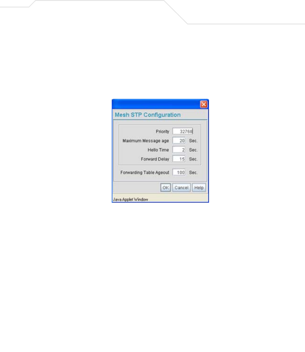
Configuring Mesh Networking 9-7
Verify the enabled LAN is named appropriately in respect to its intended function in
supporting the mesh network.
3. Select Network Configuration -> LAN -> LAN1 or LAN2 from the AP-5131 menu
tree.
4. Click the Mesh STP Configuration button on the bottom off the screen.
5. Define the properties for the following parameters within the mesh network:
Priority Set the Priority as low as possible for a to force other devices
within the mesh network to defer to this client bridge as the bridge
defining the mesh configuration (commonly referred to as the root).
Symbol recommends assigning a Base Bridge AP with the lowest
bridge priority so it becomes the root in the STP. If a root already
exists, set the Bridge Priorities of new APs accordingly so the root
of the STP doesn't get altered. Each access point starts with a
default bridge priority of 32768.
Maximum Message
age
The Maximum Message age timer is used with the Message
Age timer. The Message Age timer is used to measure the age of
the received protocol information recorded for a port, and to ensure
the information is discarded when it exceeds the value set for the
Maximum Message age timer.

AP-51xx Access Point Product Reference Guide
9-8
6. Click OK to return to either the LAN1 or LAN2 screen where updates to the Mesh STP
Configuration can be saved by clicking the Apply button.
7. Click Cancel to discard the changes made to the Mesh STP Configuration and return to
the LAN1 or LAN2 screen. Once the Mesh STP Configuration is defined, the access
point’s radio can be configured for base and/or client bridge support.
9.2.2 Configuring a WLAN for Mesh Networking Support
Each access point comprising a particular mesh network is required to be a member of the same
WLAN. Therefore, each base bridge, client bridge or repeater within the mesh network must use the
same WLAN in order to share the same ESSID, radio designation, security policy, MU ACL and Quality
of Service policy. If intending to use the access point for mesh networking support, Symbol
recommends configuring at least one WLAN (of the 16 WLANs available) specifically for mesh
networking support.
To define the attributes of the WLAN shared by the members of the mesh network:
1. Select Network Configuration -> Wireless from the AP-5131 menu tree.
Hello Time The Hello Time is the time between each bridge protocol data unit
sent. This time is equal to 2 seconds (sec) by default, but you can
tune the time to be between 1 and 10 sec. If you drop the hello time
from 2 sec to 1 sec, you double the number of bridge protocol data
units sent/received by each bridge. The 802.1d specification
recommends the Hello Time be set to a value less than half of the
Max Message age value.
Forward Delay The Forward Delay is the time spent in the listening and learning
state. This time is equal to 15 sec by default, but you can tune the
time to be between 4 and 30 sec. The 802.1d specification
recommends the Forward Delay be set to a value greater than half
the Max Message age timeout value.
Forwarding Table
Ageout
The Forwarding Table Parameter value defines the length of time
an entry will remain in the a bridge’s forwarding table before being
deleted due to lack of activity. If the entry replenishments a
destination generating continuous traffic, this timeout value will
never be invoked. However, if the destination becomes idle, the
timeout value represents the length of time that must be exceeded
before an entry is deleted from the forwarding table.
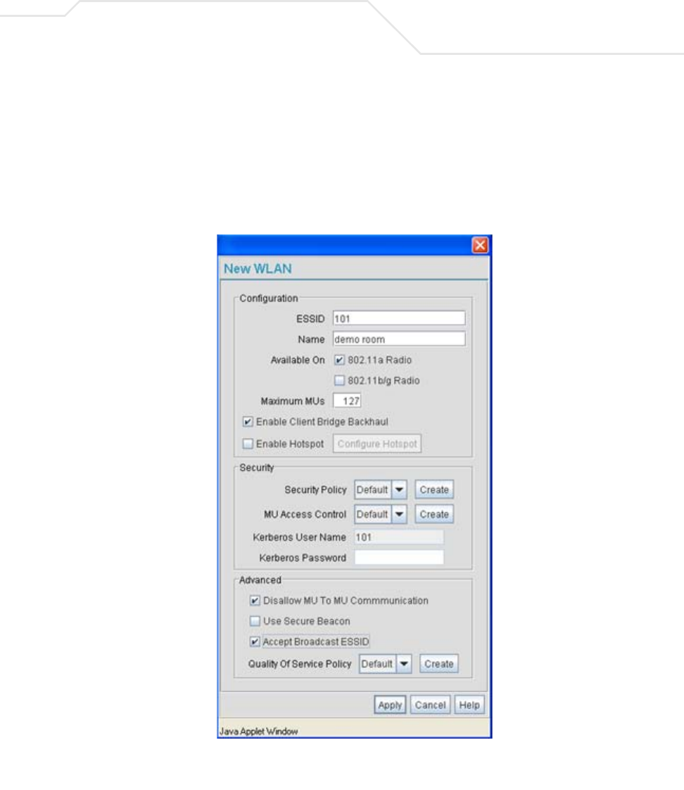
Configuring Mesh Networking 9-9
The Wireless Configuration screen displays with those existing WLANs displayed within
the table.
2. Select the Create button to configure a new WLAN specifically to support mesh
networking.
An existing WLAN can be modified (or used as is) for mesh networking support by selecting
it from the list of available WLANs and clicking the Edit button.
3. Assign an ESSID and Name to the WLAN that each access point will share when using
this WLAN within their mesh network.
AP-51xx Access Point Product Reference Guide
9-10
Symbol recommends assigning a unique name to a WLAN supporting a mesh network
to differentiate it from WLANs defined for non mesh support. The name assigned to the
WLAN is what is selected from the Radio Configuration screen for use within the
mesh network.
4. Use the Available On checkboxes to specify the access point radio(s) used with the
target WLAN within the mesh network.
The Available On checkboxes are for making this WLAN available for base bridges or
repeaters to connect to. The Available On checkbox should only be selected for a mesh
WLAN if this target access point is to be configured as a base bridge or repeater on the
radio. If the WLAN is to be defined for client bridge support only, the Available On
checkbox should not be selected. Instead, it only needs to have the Enable Client Bridge
Backhaul option selected.
5. Use the Maximum MUs field to define the number of MUs allowed to associate with
this WLAN. This number should be defined based on the number of client bridge and
repeaters within this mesh network. This value can be increased as the mesh network
grows and devices are added.
Only advanced users should define the number of devices allowed to associate with the
WLAN, as setting the value too low could restrict devices from joining an expanding
mesh network, and setting it too high could prohibit other WLANs from granting access
to the all the devices needed.
6. Select the Enable Client Bridge Backhaul checkbox to make this WLAN available in
the Mesh Network Name drop-down menu within the Radio Configuration screen.
Only WLANs defined for mesh networking support should have this checkbox selected,
in order to keep the list of WLANs available (within the Radio Configuration screen)
restricted to just WLANs configured specifically with mesh attributes.
7. Refer to the Security Policy drop-down menu to select the security policy used within
this WLAN and mesh network.
A security policy for a mesh network should be configured carefully since the data
protection requirements within a mesh network differ somewhat compared to a typical
wireless LAN. No Encryption is a bad idea in a mesh network, since mesh networks
NOTE It is possible to have different ESSID and WLAN assignments within a
single mesh network (one set between the Base Bridge and repeater and
another between the repeater and Client Bridge). However, for ease of
management and to not waste network bandwidth, Symbol recommends
using the same ESSID across the entire mesh network.
Configuring Mesh Networking 9-11
are typically not guest networks, wherein public assess is more important than data
protection. Symbol also discourages user-based authentication schemes such as
Kerberos and 802.1x EAP, as these authentication schemes are not supported within a
mesh network.
If none of the existing policies are suitable, select the Create button to the right of the
Security Policy drop-down menu and configure a policy suitable for the mesh
network. For information on configuring a security using the authentication and
encryption techniques available to the
access point, see Enabling Authentication and Encryption Schemes on page 6-5.
8. ACL policies should be configured to allow or deny a range of MAC addresses from
interoperating with the WLAN used with the mesh network. ACLs should be defined
based on the client bridge and repeater (an access point defined as both a base and
client bridge) association requirements within the mesh network.
For information on defining an ACL for use with the WLAN assigned to the mesh
network, see Configuring a WLAN Access Control List (ACL) on page 5-30.
9. Select the Disallow MU to MU Communication checkbox to restrict MUs from
interacting with each other both within this WLAN, as well as other WLANs.
Selecting this option could be a good idea, if restricting device “chatter” improves mesh
network performance. If base bridges and client bridges are added at any given time to
extent the coverage are of a mesh network, the data going back and forth amongst just
those radios could be compromised by network interference. Adding mesh device traffic
could jeopardize network throughput. If however, MU to MU communication is central
to the organization (for example, scanners sharing data entry information) then this
checkbox should remain unselected.
NOTE The Kerberos User Name and Kerberos Password fields can be
ignored, as Kerberos is not supported as a viable authentication scheme
within a mesh network.

AP-51xx Access Point Product Reference Guide
9-12
10. Select the Use Secure Beacon checkbox to not transmit the AP- 5131’s ESSID
amongst the access points and devices within the mesh network. If a hacker tries to find
an ESSID via an MU, the AP- 5131’s ESSID does not display since the ESSID is not in
the beacon. Symbol recommends keeping the option enabled to reduce the likelihood
of hacking into the WLAN.
11. Select the Accept Broadcast ESSID checkbox to associate an MU that has a blank
ESSID (regardless of which ESSID the access point is currently using). Traffic within a
mesh network probably consists of known devices, so you may want to leave the
checkbox unselected and configure each MU with an ESSID. The default is selected.
However, for WLANs used within a mesh network, Symbol recommends unselecting
this option as it would prevent the AP from answering to blank ESSID probes from other
mobile units.
12. If there are certain requirements for the types of data proliferating the mesh network,
select an existing policy or configure a new QoS policy best suiting the requirements of
the mesh network. To define a new QoS policy, select the Create button to the right of
the Quality Of Service Policy drop-down menu.
For detailed information on configuring a QoS policy, see
Setting the WLAN Quality of Service (QoS) Policy on page 5-33.
13. Click Apply to save the changes made to the mesh network configured WLAN.
An access point radio is now ready to be configured for use with this newly created
mesh WLAN.
9.2.3 Configuring the Access Point Radio for Mesh Support
An access point radio intended for use within a mesh network requires configuration attributes
unique from a radio intended for non-mesh support.This section describes how to configure an access
point radio for mesh network support.
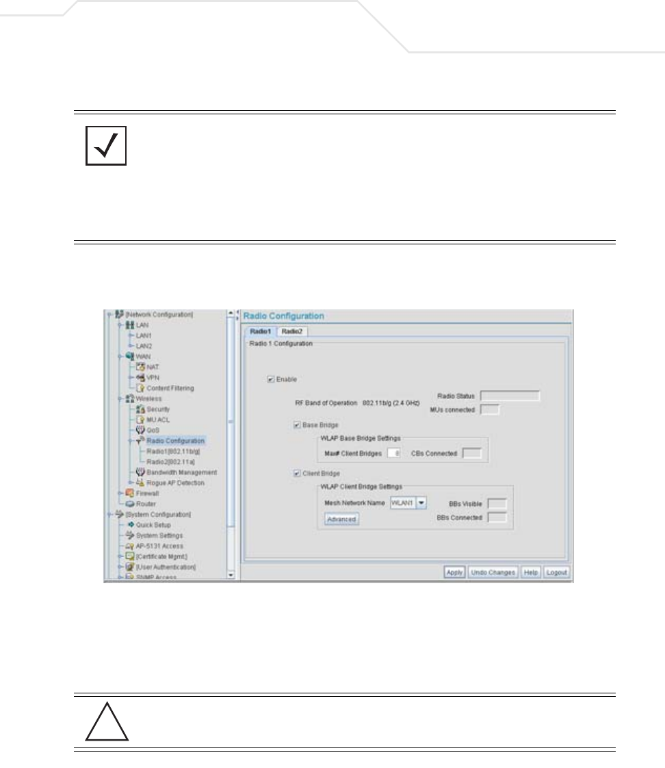
Configuring Mesh Networking 9-13
To configure the access point radio for mesh networking support:
1. Select Network Configuration -> Wireless -> Radio Configuration from the AP-5131
menu tree.
2. Enable the radio(s) using the Enable checkbox(es) for both Radio 1 and Radio 2.
Refer to RF Band of Operation parameter to ensure you are enabling the correct 802.11a
or 802.11b/g radio. After the settings are applied within this Radio Configuration screen, the
Radio Status and MUs connected values update. If this is an existing radio within a mesh
network, these values update in real-time.
NOTE The dual-radio model access point affords users better optimization of the
mesh network feature by allowing the access point to transmit to other
access points (in base or client bridge mode) using one independent radio
and transmit with its associated devices using the second independent
radio. A single-radio access point has its channel utilization and
throughput degraded in a mesh network, as the AP’s single radio must
process both mesh network traffic with other access points and MU traffic
with its associated devices.
CAUTION If a radio is disabled, be careful not to accidentally configure a new
WLAN, expecting the radio to be operating when you have forgotten it
was disabled.
!

AP-51xx Access Point Product Reference Guide
9-14
3. Select the Base Bridge checkbox to allow the access point radio to accept client bridge
connections from other access points in client bridge mode. The base bridge is the acceptor
of mesh network data from those client bridges within the mesh network and never the
initiator.
4. If the Base Bridge checkbox has been selected, use the Max# Client Bridges parameter
to define the client bridge load on a particular base bridge.
The maximum number of client bridge connections per access point radio is 12, with 24
representing the maximum for dual-radio models.
Once the settings within the Radio Configuration screen are applied (for an initial
deployment), the current number of client bridge connections for this specific radio displays
within the CBs Connected field. If this is an existing radio within a mesh network, this
value updates in real-time.
5. Select the Client Bridge checkbox to enable the access point radio to initiate client bridge
connections with other mesh network supported access points radios on the same WLAN.
CAUTION A problem could arise if a Base Bridge’s Indoor channel is not
available on an Outdoor Client Bridge's list of available channels. As
long as an Outdoor Client Bridge has the Indoor Base Bridge channel
in its available list of channels, it can associate to the Base Bridge.
CAUTION An access point in Base Bridge mode logs out whenever a Client
Bridge associates to the Base Bridge over the LAN connection. This
problem is not experienced over the access point’s WAN connection. If
this situation is experienced, log-in to the access point again.
!
!
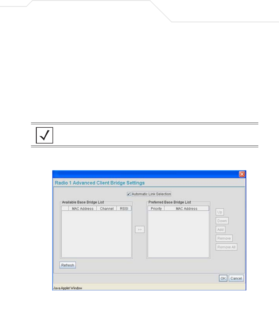
Configuring Mesh Networking 9-15
If the Client Bridge checkbox has been selected, use the Mesh Network Name drop-down
menu to select the WLAN (ESS) the client bridge uses to establish a wireless link. The
default setting, is (WLAN1). Symbol recommends creating (and naming) a WLAN specifically
for mesh networking support to differentiate the Mesh supported WLAN from non-Mesh
supported WLANs. For more information, see Configuring a WLAN for Mesh Networking
Support on page 9-8
Once the settings within the Radio Configuration screen are applied (for an initial
deployment), the current number of base bridges visible to the radio displays within the BBs
Visible field, and the number of base bridges currently connected to the radio displays
within the BBs Connected field. If this is an existing radio within a mesh network, these
values update in real-time.
6. Click the Advanced button to define a prioritized list of access points to define mesh
connection links.
7. Select the Automatic Link Selection checkbox to allow the access point to select the links
used by the client bridge to populate the mesh network. Selecting this checkbox prohibits
NOTE Ensure you have verified the radio configuration for both Radio 1 and
Radio 2 before saving the existing settings and exiting the Radio
Configuration screen.v
AP-51xx Access Point Product Reference Guide
9-16
the user from selecting the order base bridges are added to the mesh network when one of
the three associated base bridges becomes unavailable.
8. Refer to the Available Base Bridge List to view devices located by the access point using
the WLAN selected from the Radio Configuration screen. Refer the following for information
on located base bridges:
9. Click Refresh at any time to update the list of available Base Bridge devices available to the
access point.
10. Use the >> button to move a selected base bridge MAC address from Available Base Bridge
List
11. Refer to the Preferred Base Bridge List for a prioritized list of base bridges the mesh
network’s client bridge uses to extend the mesh network’s coverage area and potentially
provide redundant links. If a device does not appear on the Available Base Bridge List, there
is no" way it can be moved to Preferred Base Bridge List as the device has not yet been
"seen." However, if you know the MAC Address corresponding to that Base Bridge, you can
add that to the Preferred List using the add button.
NOTE Auto link selection is based on the RSSI and load. The client bridge will
select the best available link when the Automatic Link Selection
checkbox is selected. Symbol recommends you do not disable this option,
as (when enabled) the access point will select the best base bridge for
connection.
MAC The MAC field displays the factory set hard-coded MAC address
that serves as a device identifier.
RSSI The Relative Signal Strength Indicator (RSSI) displays the located
device’s signal strength with the associated access point in client
bridge mode. Use this information as criteria on whether to move a
particular device from the available list to the preferred list.
CHANN The CHANN displays the name of the channel that both the
access point and base bridge use. A client bridge can only connect
to access points (Base Bridges) on the same channel. If the user
selects multiple base bridges on different channels, the access
point will only be able to connect to those bridges on the same
channel and the others will not be able to join this particular mesh
network.

Configuring Mesh Networking 9-17
12. Highlight a MAC address from the Preferred Base Bridge List and click the Up button to
assign that device’s MAC address a higher priority and a greater likelihood of joining the
mesh network if an association with another device is lost.
If a MAC address is not desirable as others but still worthy of being on the preferred list,
select it, and click the Down button to decrease its likelihood of being selected as a member
of the mesh network.
13. If a device MAC address is on the Preferred Base Bridge List and constitutes a threat as a
potential member of the mesh network (poor RSSI etc.), select it and click the Remove
button to exclude it from the preferred list.
If all of the members of the Preferred Base Bridge List constitute a risk as a member of the
mesh network, click the Remove All button. This is not recommended unless the preferred
list can be re-populated with more desirable device MAC addresses from the Available Base
Bridge List.
14. Click Ok to return to the Radio Configuration screen. Within the Radio Configuration screen,
click Apply to save any changes made within the Advanced Client Bridge Settings screen.
15. Click Cancel to undo any changes made within the Advanced Client Bridge Settings screen.
This reverts all settings for the screen to the last saved configuration.
16. Click Apply to save any changes to the Radio Configuration screen. Navigating away from
the screen without clicking Apply results in all changes to the screens being lost.
17. Click Undo Changes (if necessary) to undo any changes made. Undo Changes reverts the
settings displayed on the Radio Configuration screen to the last saved configuration.
18. Click Logout to securely exit the AP-5131 Symbol Access Point applet. A prompt displays
confirming the logout before the applet is closed.
Once the target radio has been enabled from the Radio Configuration screen, configure
the radio’s properties by selecting it from the AP-5131 menu tree.
CAUTION When defining a Mesh configuration and changes are saved, the
mesh network temporarily goes down. The mesh network is
unavailable because the access point radio goes down when applying
the changes. This can be problematic for users making changes within
a deployed mesh network. If updating the mesh network using a LAN
connection, the access point applet loses connection and the
connection must be re-instated. If updating the mesh network using a
WAN connection, the access point applet does not lose connection,
but the mesh network is unavailable until the changes have been
applied.
!

AP-51xx Access Point Product Reference Guide
9-18
For additional information on configuring the access point’s radio, see Configuring the
802.11a or 802.11b/g Radio on page 5-47. For fictional use case involving an access point
mesh network deployment within a shipping and receiving yard, see Usage Scenario - Trion
Enterprises on page 9-19.
Configuring Mesh Networking 9-19
9.3 Usage Scenario - Trion Enterprises
Trion Enterprises is a new shipping and receiving company. Trion wants to create an outdoor wireless
coverage area (in addition to its indoor wireless infrastructure) that can expand as they grow their
business. As Trion expands the wireless coverage area within their shipping yard, they will need
additional access points configured as either base or client bridges or repeaters (access points
configured as both base and client bridges) to support the growing number of MUs, and forward data
traffic to the client bridges on the outer areas of the mesh network. The MUs within the shipping and
receiving area consist primarily of Symbol bar code scanners (to monitor Trion’s inventory coming and
going) as well as PDAs doing data entry.
9.3.1 Trion’s Initial Deployment
Trion’s initial requirement is to configure a “point-to-point” mesh network consisting of two access
points (AP1 and AP2). AP1 is to be physically connected to a pole inside the entrance to the shipping
and receiving area with antennas oriented outward into the shipping yard. AP1 is intended to be a
base bridge with no coverage for MUs within the shipping yard. AP2 is intended to be a client bridge
associated to AP1 and be placed on a wall of a receiving shack (a remote building in the shipping yard)
with antennas oriented into the shipping yard. AP2 also is also connected to a Symbol ES3000
wireless switch providing connectivity (on its own local subnet) to laptops within the receiving shack.
AP1 and AP2 will be configured identically unless noted.
To configure Trion’s initial deployment, the IT Team does the following:
NOTE The information presented within this use case is centered around the
configuration of the mesh networking feature exclusively. It is assumed
the access points used by Trion Enterprises are completely configured
(beyond the mesh networking functionality) before being deployed in their
shipping yard.
NOTE To optimize Trion’s mesh network, the IT team decides to create a mesh
WLAN to strictly support the base bridge, client bridge and repeater
traffic within the mesh network. This is the configuration described in this
use case. However, to optimally support the MU traffic within the
shipping yard, the Trion team should create a separate (non-mesh) WLAN
to support the MU traffic proliferating the shipping yard. To configure the
separate (non mesh) WLAN, the IT team follows the instructions in
Creating/Editing Individual WLANs on page 5-24.
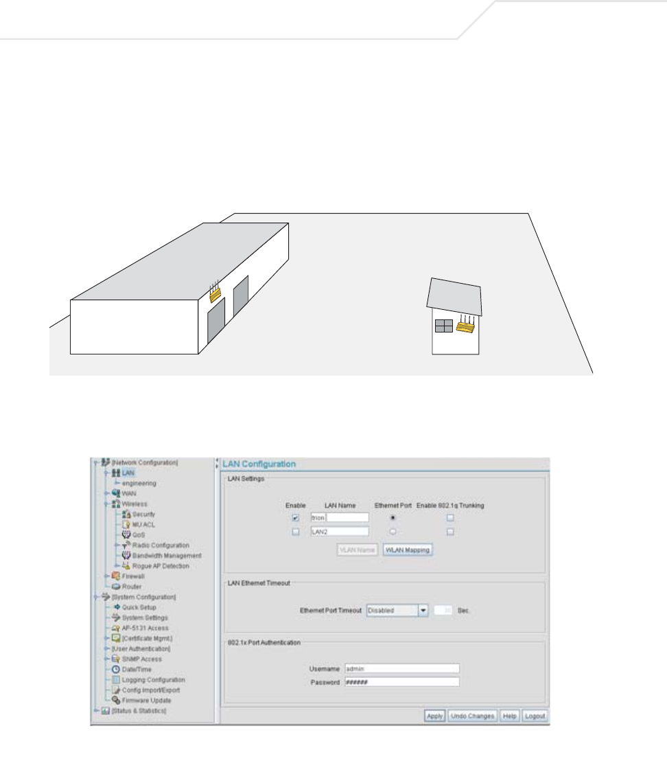
AP-51xx Access Point Product Reference Guide
9-20
1. The Trion IT department verifies connectivity with both of the access points following the
instructions in Testing Connectivity on page 3-11.
2. The Trion IT Department installs the AP1 on a wall with the antennas orienting outward into
the shipping and receiving yard. The team then installs the AP2 on a wall on the receiving
shack in the shipping yard.
The Trion IT department follows the instructions in
Wall Mounted Installations on page 2-14 to install AP1 and AP2.
3. The Trion IT department selects Network Configuration -> LAN from the AP-5131 menu
tree.
AP1
AP2
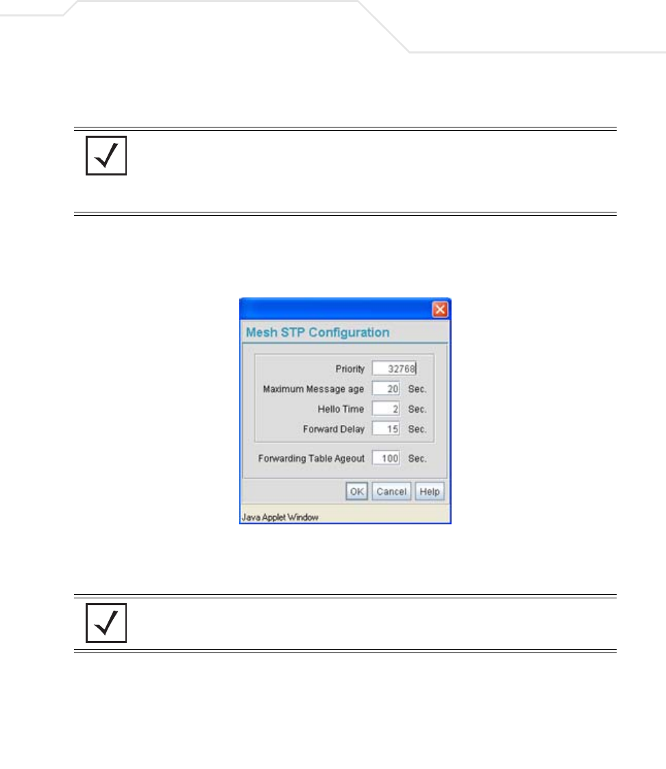
Configuring Mesh Networking 9-21
4. The Trion IT department verifies the LAN used to support the mesh network is enabled for
both AP1 and AP2, (by selecting the Enable checkbox).
5. The Trion IT department then selects Network Configuration -> LAN -> trion from the
AP-5131 menu tree.
6. The IT team selects the Mesh STP Configuration button on the bottom off the screen.
7. The Trion IT department sets the Priority setting to 1 (for AP1) in order for future members
of the mesh network to defer to AP1 as the AP defining the mesh network configuration
(setting this value to 1 AP1 to what is commonly referred to as the root).
The IT team leaves the Maximum Message age timer at the 20 sec default interval. This
setting controls the maximum length of time that passes before a bridge port saves its
configuration information. The Hello Time (the time between each bridge protocol data unit
sent) is also unchanged from 2 second default interval. The IT team also leaves the Forward
Delay (the time the access point LAN is spent in a listening and learning state) to the factory
NOTE In this fictional mesh network deployment for Trion Enterprises, AP1 and
AP2 should both have the access point’s Ethernet Port mapped to the
mesh LAN. However, there are some scenarios when this is not necessary.
For example, when the Ethernet is not connected, or is being used for
some other purpose such as routing traffic to the WAN connection.
NOTE AP1 and AP2 have been configured identically up to this point. However,
only AP1 is assigned a priority of 1 within the Bridge STP Configuration
screen. AP2 is set to a lower priority (100) to keep AP1 as the root.

AP-51xx Access Point Product Reference Guide
9-22
default of 15 seconds. Since only one additional access point is to be added to this point-to-
point mesh network, the Forwarding Table Ageout value is also unchanged from its 100
second default setting.
8. The team clicks OK from within the Bridge STP Configuration screen and Apply from within
the trion (LAN1) screen to save the settings. This step is repeated for AP2.
The Trion IT team now intends to create a WLAN (to use with the trion LAN) that can be
dedicated to their mesh network within the shipping yard.
9. Select Network Configuration -> Wireless from the AP-5131 menu tree.
The Wireless Configuration screen displays with those existing WLANs displayed within
the table. This is Trion’s first deployment for this new dual-radio access point, upon
reviewing the Wireless Page they determine the existing default WLAN should be left as is
and a new WLAN should be created that can be dedicated to the mesh network supporting
the shipping yard.
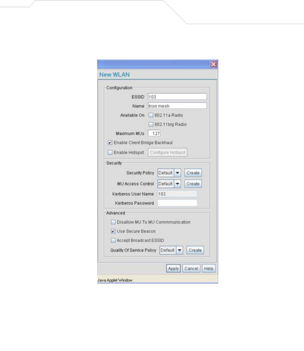
Configuring Mesh Networking 9-23
10. The team selects the Edit button to revise (and rename) the existing WLAN specifically
to support mesh networking.
11. The Trion IT team assigns the WLAN a unique ESSID (103) used by each new base bridge,
client bridge and repeater joining the mesh network.
12. The team assigns the name of “trion mesh” to the WLAN so it will not be confused with
other WLANs used in other areas of the Trion facility. This name also serves to associate the
name of the WLAN with its intended mesh network utilization of data. entry within the
shipping yard

AP-51xx Access Point Product Reference Guide
9-24
13. For AP1 the team selects the 802.11a checkbox. Enabling the 802.11a radio for the mesh
WLAN and configuring a separate WLAN for MU traffic (using the 802.11b/g radio), allows
the team the best channel utilization and throughput available since the 802.11a radio can
be dedicated strictly to communications within the mesh network and the 802.11b/g radio
can be dedicated to servicing the 802.11b/g MUs supporting the shipping and receiving
yard.
For AP2, neither the 802.11a or 802.11b/g checkboxes are selected (see the screen
displayed above). Only the Enable Client Bridge Backhaul checkbox needs to be selected
for AP2 (as AP2 will be used as a client bridge).
14. The team does not want any MUs connecting to the mesh WLAN, only the client bridges
comprising the mesh network. Therefore, the team leaves the Maximum MUs field as is,
and will use the Radio Configuration page to control the number of client bridge
connections.
15. The team verifies the Enable Client Bridge Backhaul checkbox is selected for AP2 to
ensure the WLAN is available in the Mesh Network Name drop-down menu.
Unlike the user-based Kerberos authentication scheme used within the Trion Administrative
office and the 802.1x EAP scheme used in the Finance department, the IT Team wants to
configure a security scheme for the WLAN that emphasizes security for the data
proliferating the shipping yard, not its user base, as users may come and go whereas the
data traffic within the shipping yard remains continuous.
16. The IT Team selects the Create button to the right of the Security Policy drop-down menu.
The New Security Policy screen displays with no authentication or encryption options
selected.
17. The IT Team selects the WPA2/CCMP radio button.
The WPA2/CCMP Settings field displays within the New Security Policy screen.
18. The IT Team assigns a name of “WPA2 mesh network” to not only define the security
scheme used, but associate this policy with its intended use for the shipping and receiving
mesh network.
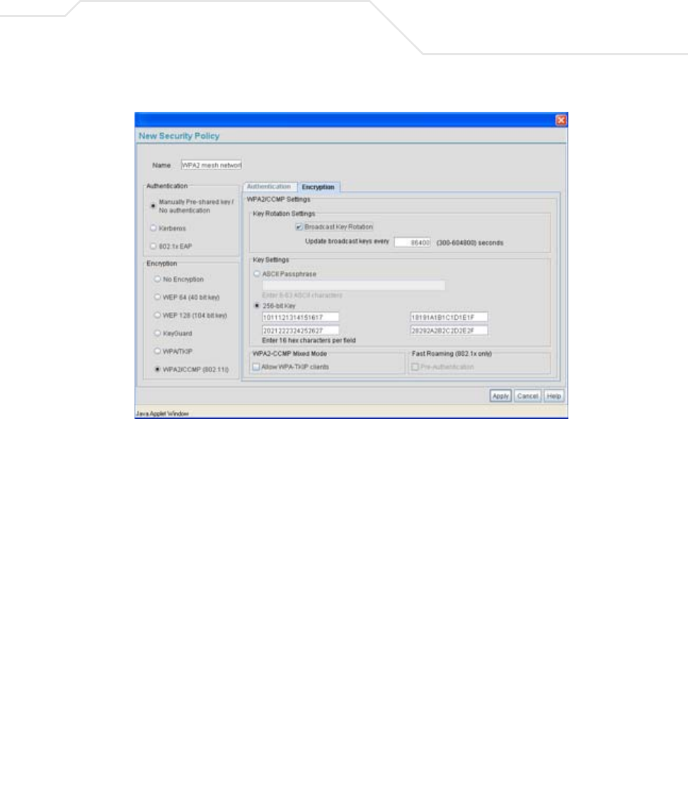
Configuring Mesh Networking 9-25
19. The Broadcast Key Rotation checkbox is selected, as the IT team plans to change the keys
from time to time (for security purposes) and wants these keys to be broadcasted using the
default interval 86400 seconds.
20. The IT team does not want to use a passphrase to represent the 256-bit keys, so the 256-
bit Key checkbox is selected, and the team enters 16 hexadecimal characters into each of
the four fields displayed. Once completed the Apply button is selected and the access point
applet returns to the WLAN screen.
21. The team leaves the Allow WPA-TKIP clients and Pre-Authentication checkboxes
unselected.
Since the Trion Shipping and Receiving yard is considered a secure wireless network with
MU traffic comprised of known 802.11b/g MUs with fixed MAC addresses, the IT team
wants to create an ACL that excludes all MU traffic except the known range of Trion
Enterprises deployed MAC addresses.
22. From back at the Edit WLAN screen, the IT team selects the Create button (to the right of
the MU Access Control drop-down menu.
The New MU ACL Policy screen displays with no existing MAC address ranges.
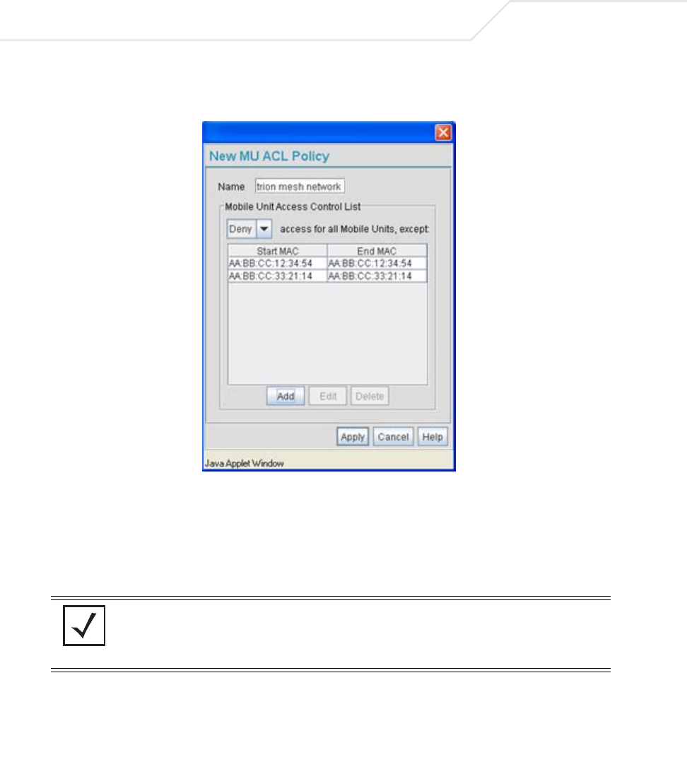
AP-51xx Access Point Product Reference Guide
9-26
23. The IT team assigns the name of “trion mesh network” to the ACL to eliminate any
confusion with the ACLs intended function
24. Since the range of client bridge MAC addresses for the shipping yard mesh network is
known to the IT Team, they select the Deny drop-down menu option, as the team wants to
deny access to all MAC addresses except their own known range of device MAC addresses.
25. The IT team then selects the Add button and enters the base bridge MAC address that will
be granted access to the access point managed WLAN. Once completed, the Apply button
is selected and the access point applet returns to the WLAN screen.
Now a QoS policy needs to be defined for the shipping and receiving mesh network WLAN.
The IT Team envisions little if any video or voice traffic within the shipping yard as the MUs
within primarily scan bar codes and upload data.
NOTE If the Trion IT team puts the client bridge addresses into the ACL, they
should also put the access point’s BSS ID into the ACL since there is no
way to know ahead of time which BSS the client bridge will use for
association.
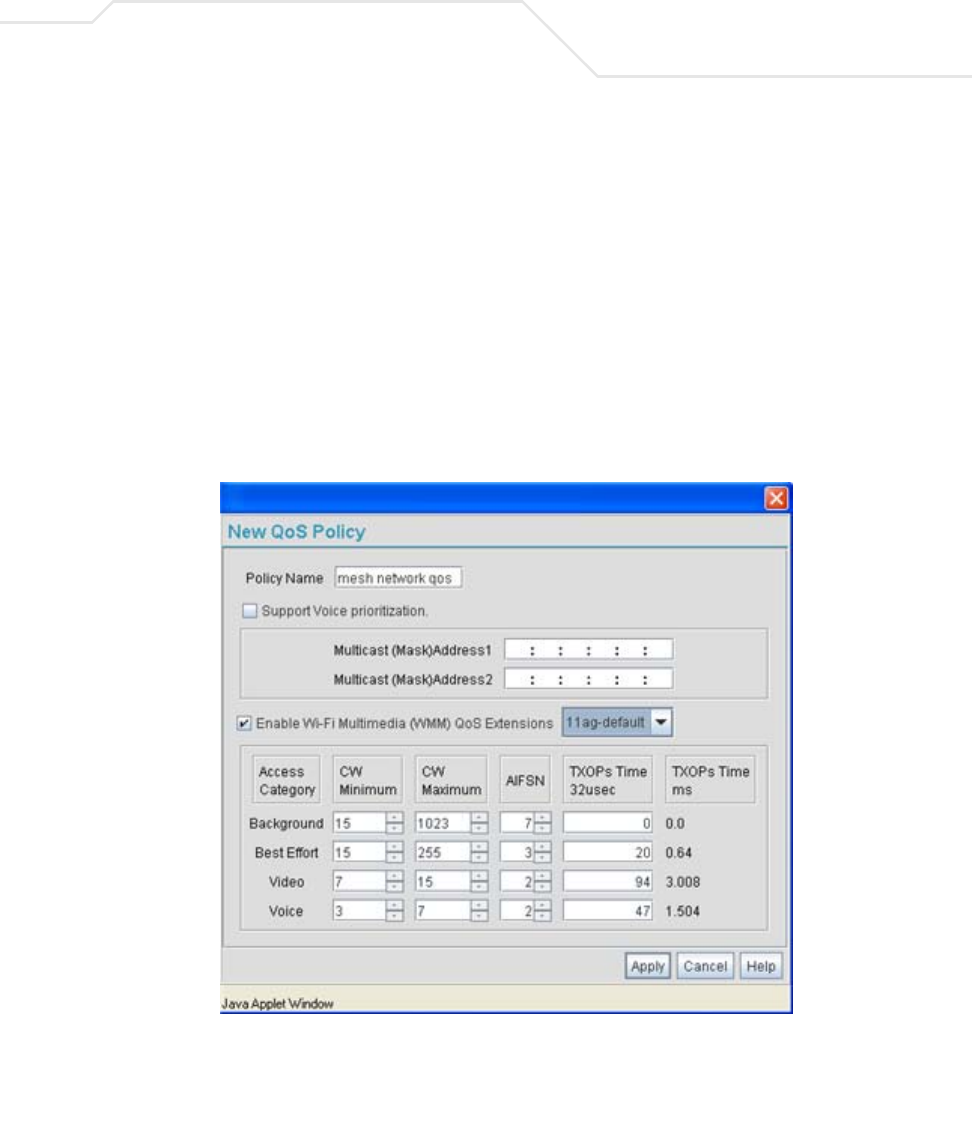
Configuring Mesh Networking 9-27
26. The team decides to leave the Disallow MU to MU Communication checkbox unselected
for the WLAN, as the team considers all MU traffic within the secure shipping and receiving
yard known and not a threat to the initial 2 AP mesh network deployment.
27. The team selects the Use Secure Beacon checkbox from the Edit WLAN screen to not
transmit the AP- 5131’s ESSID between AP1 and AP2. If a hacker tries to find an ESSID via
an MU, the AP- 5131’s ESSID does not display since the ESSID is not in the beacon.
28. The team does not select the Accept Broadcast ESSID checkbox from the Edit WLAN
screen to associate MUs with a blank ESSID, as they do not want MUs randomly joining
their carefully constructed mesh network.
29. From the Edit WLAN screen, the IT Team selects the Create button to the right of the Quality
Of Service Policy drop-down menu.
The New QoS Policy screen displays with no values selected.
30. The IT Team assigns the name of “mesh network qos” to the QoS policy to eliminate any
confusion with the policy’s intended function.

AP-51xx Access Point Product Reference Guide
9-28
31. The IT Team does not plan on supporting any legacy 802.11b voice enabled devices, so they
leave the Support Voice prioritization checkbox unselected.
32. The IT Team selects 11ag-default from the drop-down menu to best describe the type of
data proliferating the mesh network. With this setting selected, the Access Category
settings do not need to be configured for the QoS policy.
33. The IT Team selects the Enable Wi-Fi Multimedia (WMM) QoS Extensions checkbox,
and selects the 11ag-default setting for the intended traffic within the WLAN. If
multimedia or voice traffic would have proliferated the WLAN, the team would have
selected 11ag-wifi or 11ag-voice. However, since simple data transfers are planned, the
11ag-default setting is appropriate.
34. The IT Team clicks Apply within both the New QoS Policy and Edit WLAN screen to save
the settings to the mesh network WLAN. The configuration process is repeated and saved
for AP2.
The WLAN configuration has now been set similarly for both AP1 and AP2 (with the
exception of the Priority setting within the Mesh STP Configuration screen). The team now
needs to define the radio configuration for both AP1 and AP2.
35. The IT team selects Network Configuration -> Wireless -> Radio Configuration from
the AP-5131 menu tree.
The Radio Configuration screen displays.
36. For AP1, the IT Team enables both Radio 1 and Radio 2 and defines radio 1 as a base bridge.
AP1 is intended to pass along mesh network data to AP2 (as well as other access points as
they are added to the mesh network).
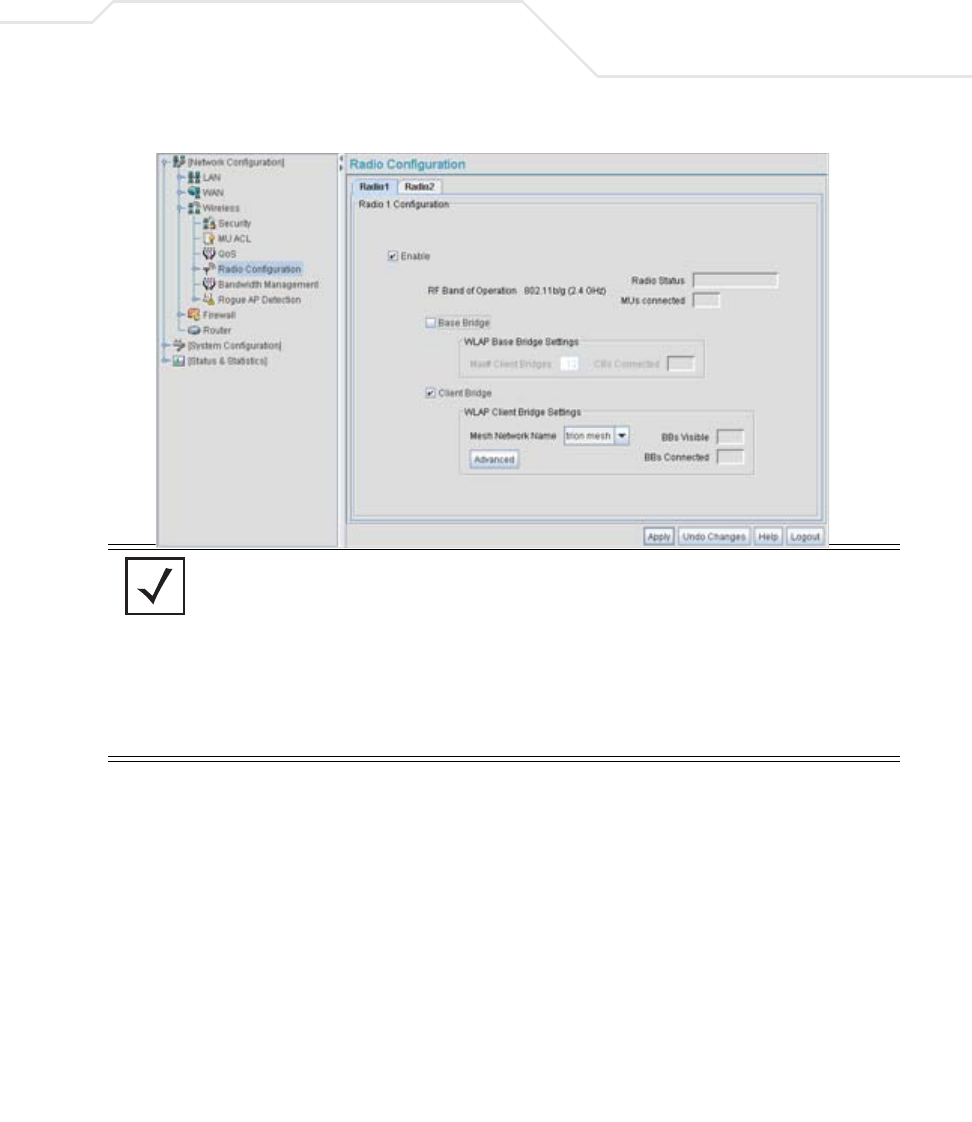
Configuring Mesh Networking 9-29
37. For AP2, the IT Team enables both Radio 1 and Radio 2 and defines radio 1 as a client bridge.
38. The IT Team leaves each radio’s Max # Client Bridge setting at the default setting of 12.
This ensures as client bridges are added to the growing mesh network they can be
accounted for.
39. For AP1 and AP2, the IT Team uses the Mesh Network Name drop-down menu to assign
the “trion mesh” WLAN to the radio 1 client bridge. This is the WLAN the AP1 and AP2
radios will use to interoperate with the mesh network devices populating the shipping yard.
40. The IT Team decides to not select the Advanced button within the AP1 and AP2 WLAP
Client Bridge Settings field.
For the next six months, Trion Enterprises’ mesh network only consists of AP1 and AP2. AP1
has already been defined as the root bridge in the mesh network when it was assigned a
Priority value of 1 within the Bridge STP Configuration screen.
NOTE The Trion IT team is aware it is not a good idea to dedicate both radios (of
a dual-radio model access point) to support mesh networking. They know
it is possible to dedicate both radios of a single access point for mesh
support, but the Trion team wants to dedicate the 802.11b/g radio for MU
operation and the 802.11a radio for backhaul support. For AP2, the Trion
team will create two connections to AP1 (one over the 802.11b/g radio
and one over the 802.11a radio). The connection used for forwarding data
for AP2 will be the 802.11b/g radio and the 802.11a radio will be
dedicated for client bridge backhaul.
AP-51xx Access Point Product Reference Guide
9-30
41. The Trion IT Team clicks Apply within both the AP1 and AP2 Radio Configuration screens to
complete the mesh network configuration of each AP1 and AP2 radio. The team does not
worry about network disruption by applying the settings at this point, as AP1 and AP2 have
not yet been deployed. However, in the future they are aware saving their mesh
configuration will temporarily disrupt service within their mesh network.
9.3.2 Adding 2 Client Bridges to Expand the Coverage Area
After a prosperous six months with their existing 2 access point mesh network, Trion Enterprises
needs and approves the addition of two additional access points (AP3 and AP4) to be configured as
repeaters (both client and base bridges). Configuring AP3 and AP4 as repeaters entails configuring an
AP3 and an AP4 radio as both a client bridge and a base bridge.
To configure AP3 and AP4 as repeaters, the IT Team does the following:
1. The Trion IT department verifies connectivity with AP3 and AP4 following the instructions in
Testing Connectivity on page 3-11.
2. The Trion IT Department installs AP3 and AP4 on light poles (in the middle of the shipping
yard) where power is available and a secure mesh network (AP1 and AP2) is already within
NOTE With the mesh network configuration completed for AP1 and AP2, the
Trion Enterprises IT team completes the configuration of the APs following
the instructions in this access point Product Reference Guide. Later in the
year Trion expects to grow their business to the point where 2 new client
bridges are required to provide mesh networking to new areas of their
shipping year. See,
Adding 2 Client Bridges to Expand the Coverage Area on page 9-30.
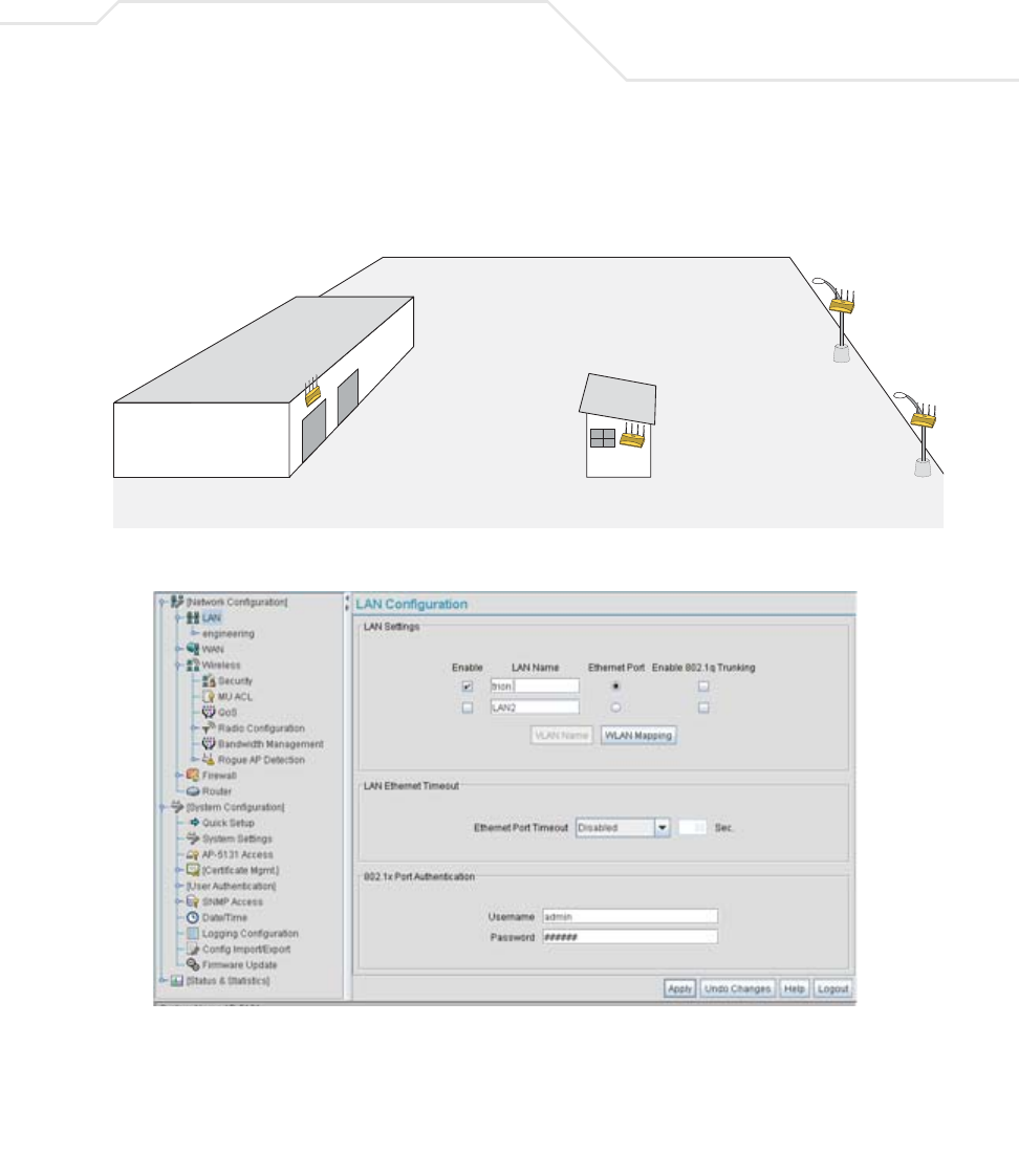
Configuring Mesh Networking 9-31
broadcast range (see the illustration below). The Trion IT department follows the
instructions in Wall Mounted Installations on page 2-14 to install AP3 and AP4.
3. The Trion IT department selects Network Configuration -> LAN from the AP-5131 menu
tree.
4. The Trion IT department verifies the LAN used to support the mesh network is enabled for
both AP3 and AP4, (by selecting the Enable checkbox).
5. The Trion IT department then selects Network Configuration -> LAN -> trion from the
AP-5131 menu tree.
6. The IT team selects the Mesh STP Configuration button on the bottom of the screen.
AP1
AP2
AP3
AP4
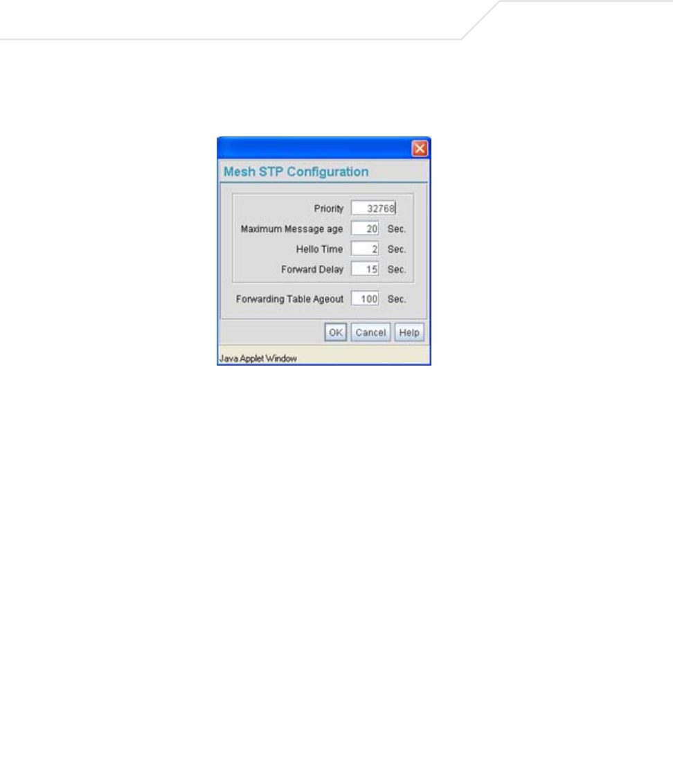
AP-51xx Access Point Product Reference Guide
9-32
7. The Trion IT department leaves the Priority setting to at 32768 for AP3 and AP4 for both to
defer to AP1 (which was assigned a priority of 1 for root designation) as the access point
defining the mesh network configuration.
The remainder of the Mesh STP Configuration settings are left unchanged from their default
values. The team clicks OK from within the Mesh STP Configuration screen and Apply from
within the trion (LAN1) screen to save the settings.
The Trion IT team now intends to assign WLANs (to use with the trion LAN) that can be
dedicated to their mesh network within the shipping yard.
8. The team selects Network Configuration -> Wireless from the AP-5131 menu tree.
The Wireless Configuration screen displays with those existing WLANs displayed within
the table. Since this is Trion’s first deployment for AP3 and AP4, the IT department
determines the existing default WLAN should be left as is, and a new WLAN should be
configured closely resembling the mesh network WLAN defined for AP1 and AP2.
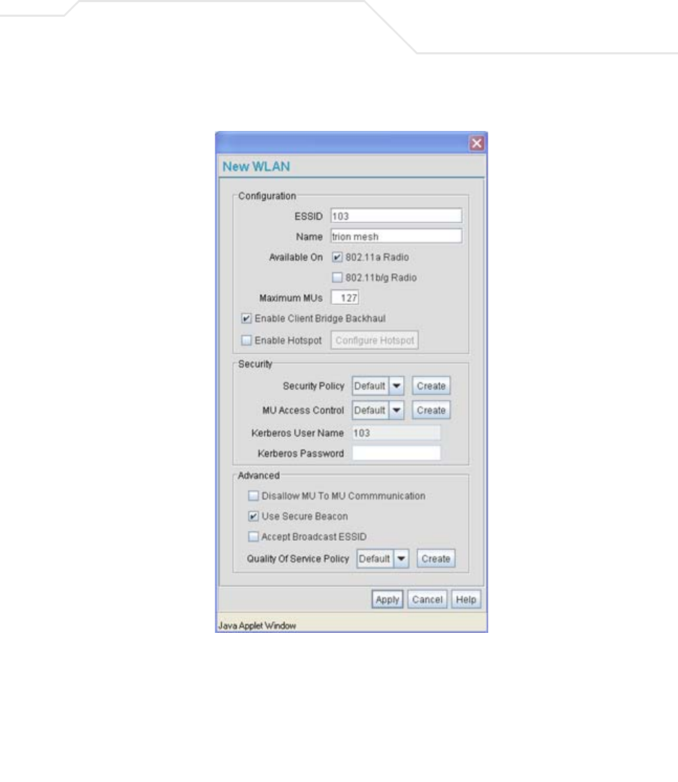
Configuring Mesh Networking 9-33
9. The team selects the Edit button to revise (and rename) the existing default WLAN to
support mesh networking.
10. The Trion IT team assigns AP3 and AP4 an ESSID of 103. Therefore, AP1 and AP2 should be
able to “see” AP3 and AP4 as soon as they are deployed.
11. The team assigns the name of “trion mesh” to the WLAN to be consistent with the WLAN
supporting mesh networking on AP1 and AP2.
12. The team selects the 802.11a Radio checkbox for both AP3 and AP4. Like AP1, the 802.11b/
g radios will be used to service MUs on a different WLAN, thus segregating MU traffic from
the mesh traffic proliferating the 802.11a radio.

AP-51xx Access Point Product Reference Guide
9-34
13. The team does not want any MUs connecting to the mesh WLAN, only the devices
comprising the mesh network. Therefore, the team leaves the Maximum MUs field as is,
and will use the Radio Configuration page to control the number of client bridge
connections.
14. The team verifies the Enable Client Bridge Backhaul checkbox is selected for both AP3
and AP4 to ensure the WLAN is available in the WLAN drop-down menu within the Radio
Configuration screen.
15. The IT team then verifies that steps 10 through 14 have been carried out identically for both
AP3 and AP4.
The IT team now needs to define a security policy for AP3 and AP4 complimentary with the
policy created for AP1 and AP2 to both protect the data within the mesh network and ensure
all 4 access points within the network can interact with one another.
16. The IT Team selects the Create button to the right of the Security Policy drop-down menu
and defines a WPA2/CCMP supported security policy exactly like the one created for AP1
and AP2. For more information, see how the team defined the security policy starting on step
16 within Trion’s Initial Deployment on page 9-19.
It is assumed all of the existing MU traffic defined for AP1 and AP2 will also be used in the
extended coverage area for AP3 and AP4 with no known additions to the MU traffic at this
time. Thus the IT team refers to the ACL created for AP1 and AP2 and defines an ACL exactly
like it for AP3 and AP4.
17. The team selects the Create button (to the right of the MU Access Control drop-down
menu and defines an ACL policy like the one created for AP1 and AP2. The team also
remembers to go to the AP1 ACL and add AP3 and AP4 to the list of devices allowed to
connect to AP1.
For more information, see how the team defined the ACL policy starting on step 22 within
Trion’s Initial Deployment on page 9-19.
18. The team decides to leave the Disallow MU to MU Communication checkbox unselected
for the mesh WLAN for AP3 and AP4, as the team still considers all MU traffic within the
shipping yard known and not a threat to the growing mesh network.
19. The team selects the Use Secure Beacon checkbox from the Edit WLAN screen to not
transmit the AP- 5131’s ESSID between APs 1 through 4. If a hacker tries to find an ESSID
via an MU, the AP- 5131’s ESSID does not display since the ESSID is not in the beacon.
20. The team does not select the Accept Broadcast ESSID checkbox, as they still do not want
MUs randomly joining their carefully constructed mesh network.
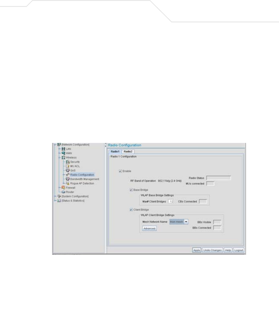
Configuring Mesh Networking 9-35
21. Now a QoS policy needs to be defined for the shipping and receiving mesh WLAN. The IT
Team still envisions little (if any) video or voice traffic within the shipping as the MUs within
primarily scan bar codes and upload data. This holds true for the QoS requirements for AP3
and AP4 as the required coverage area has grown, not the security, access permission or
QoS considerations. For more information, see how the team defined the AP1 and AP2 QoS
policy starting on step 25 within Trion’s Initial Deployment on page 9-19.
The WLAN configuration has now been set for both AP3 and AP4. The team now needs to
define the radio configurations for AP3 and AP4.
22. The IT team selects Network Configuration -> Wireless -> Radio Configuration from
the AP-5131 menu tree.
The Radio Configuration screen displays.
23. For both AP3 and AP4, the IT Team enables Radio 1 and defines the radio as a repeater
(enabling each radio as both a base and client bridge).
Both AP3 and AP4 are intended to pass along mesh network back data to AP1 and support
the 802. 11b/g MUs within the shipping yard.
24. The IT Team leaves each radio’s Max # Client Bridge setting at the default setting of 12.
This ensures as client bridges are added to the growing mesh network that they can be
accounted for.
25. For both AP3 and AP4, the IT Team uses the Mesh Network Name drop-down menu to
assign the “trion mesh” WLAN to radio 1. This is the WLAN the AP3 and AP4 radios will
use to interoperate with the MUs populating the shipping yard.

AP-51xx Access Point Product Reference Guide
9-36
26. As with AP1 and AP2, the IT Team decides to not select the Advanced button within the
AP3 and AP4 WLAP Client Bridge Settings field.
27. The Trion IT Team clicks Apply within both the AP3 and AP4 Radio Configuration screens to
complete the mesh network configuration of each AP3 and AP4 radio.
For the next 9 months, the Trion Enterprises’ mesh network consists of AP1 and AP2 and now
AP3 and AP4 extending the mesh coverage range further into the shipping yard. AP1 is still
the root bridge in the mesh network. The IT Team will appraise their mesh requirements in
another 9 months and (if necessary) add additional access points and MUs to the mesh
network.
Configuring Mesh Networking 9-37
9.3.3 Adding 2 More Client Bridges to the Trion Network
After an additional six months with their existing 4 access point mesh network, Trion Enterprises
needs and approves the addition of two additional access points (AP5 and AP6) to be configured as
client bridges. The team will configure AP5 and AP6 as client bridges and not base bridges or
repeaters since Trion Enterprises does not plan to expand its shipping yard and the mesh network
would have all the access points needed to support it. Thus, one AP5 and AP6 radio will be providing
mesh coverage to the outer portion of the shipping yard without having to provide base bridge or
repeater support to new members of the mesh network. The remaining AP5 and AP5 radio can support
shipping yard MU traffic using a non-mesh WLAN.
To configure AP5 and AP6 as client bridges, the IT Team does the following:
1. The Trion IT department verifies connectivity with AP5 and AP6 following the instructions in
Testing Connectivity on page 3-11.
2. The Trion IT Department installs AP5 and AP6 on light poles (in a new expanded are of the
shipping yard) where power has been made available and a secure mesh network (APs 1-4)
is within broadcast range (see the illustration below). The Trion IT department follows the
instructions in Wall Mounted Installations on page 2-14 to install AP5 and AP6.
s
AP1
AP2 AP3
AP4
AP5
AP6
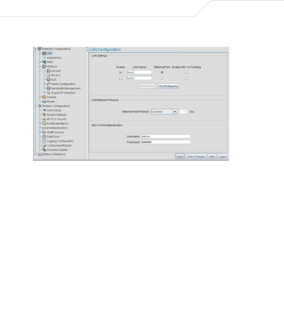
AP-51xx Access Point Product Reference Guide
9-38
3. The Trion IT department selects Network Configuration -> LAN from the AP-5131 menu
tree.
4. The Trion IT department verifies the LAN used to support the mesh network is enabled for
both AP5 and AP6, (by selecting the Enable checkbox).
5. The Trion IT department then selects Network Configuration -> LAN -> trion from the
AP-5131 menu tree.
6. The IT team selects the Mesh STP Configuration button on the bottom of the screen.
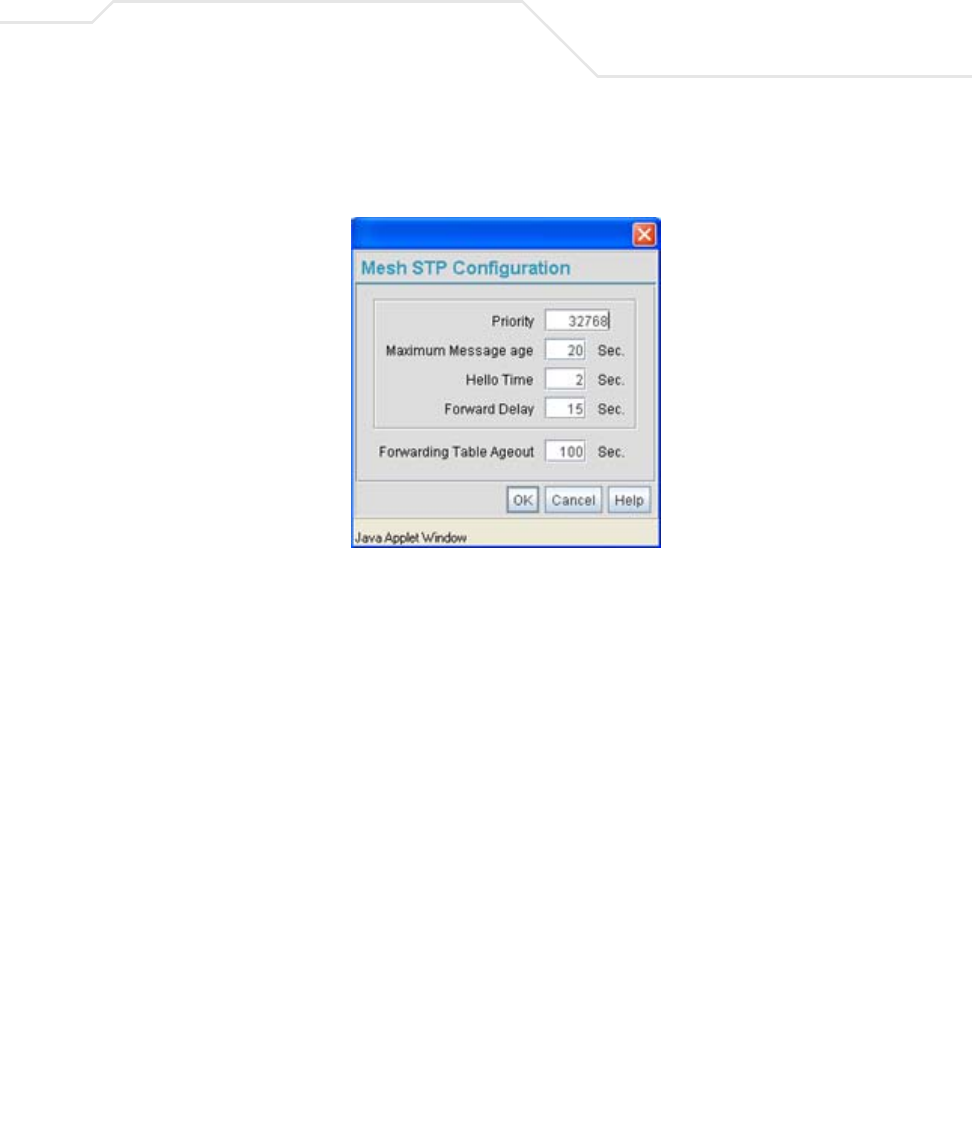
Configuring Mesh Networking 9-39
7. The Trion IT department leaves the Priority setting to at 32768 for AP5 and AP6 for both to
defer to AP1 (which was assigned a priority of 1 for root designation) as the access point
defining the mesh network configuration.
The remainder of the Mesh STP Configuration settings are left unchanged from their default
values. The team clicks OK from within the Mesh STP Configuration screen and Apply from
within the trion (LAN1) screen to save the settings.
The Trion IT team now intends to assign WLANs (to use with the trion LAN) that can be
dedicated to their mesh network within the shipping yard.
8. The team selects Network Configuration -> Wireless from the AP-5131 menu tree.
The Wireless Configuration screen displays with those existing WLANs displayed within
the table. Since this is Trion’s first deployment for AP5 and AP6, the IT department
determines the existing default WLAN should be left as is, and a new WLAN should be
configured resembling the mesh network WLAN defined for APs 1-4.
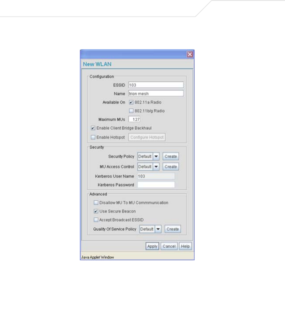
AP-51xx Access Point Product Reference Guide
9-40
9. The team selects the Edit button to revise (and rename) the existing default WLAN to
support mesh networking.
10. The Trion IT team assigns the WLAN an ESSID of 103 to be consistent with the trion mesh
WLAN ESSID of the other four access points within the mesh network.
11. The team assigns the name of “trion mesh” to the WLAN to be consistent with the WLAN
supporting mesh on APs 1-4.
12. The team selects the 802.11a Radio checkbox for both AP5 and AP6. The 802.11b/g radio on
both AP5 and AP6 will be used to service MUs (on a different WLAN). Thus, MU traffic will
be segregated from the mesh traffic proliferating each AP’s 802.11a radio.

Configuring Mesh Networking 9-41
13. The team still does not want any MUs connecting to the mesh WLAN, only the devices
comprising the mesh network. Therefore, the team leaves the Maximum MUs field as is,
and will use the Radio Configuration page to control the number of client bridge connections
within the mesh WLAN.
14. The team verifies the Enable Client Bridge Backhaul checkbox is selected for both AP5
and AP6 to ensure the WLAN is available in the WLAN drop-down menu within the Radio
Configuration screen.
15. The IT team then verifies that steps 10 through 14 have been carried out identically for both
AP5 and AP6.
The IT team now needs to define a security policy for AP5 and AP4 complimentary with the
policy created for APs 1-4.
16. The IT Team defines a WPA2/CCMP security policy exactly like the one created for APs 1-4.
For more information, see how the team initially defined the security policy starting on step
16 within Trion’s Initial Deployment on page 9-19.
17. Existing MU traffic within the mesh network will be used within the expanded shipping yard.
Thus, the IT team refers to the ACLs created for APs 1-4 and defines an ACL exactly like it
for AP5 and AP6. The team also remembers to go to the ACL for AP1, AP3 and AP4 and add
AP5 and AP6 in order for each device in the mesh network to communicate with one another.
For more information, refer to step 22 within Trion’s Initial Deployment on page 9-19.
18. The team decides to leave the Disallow MU to MU Communication checkbox unselected
for AP5 and AP6, as the team still considers all MU traffic within the shipping yard known
and not a threat to the growing mesh network.
19. The team selects the Use Secure Beacon checkbox from the Edit WLAN screen to not
transmit the AP- 5131’s ESSID between APs 1 through 6. If a hacker tries to find an ESSID
via an MU, the AP- 5131’s ESSID does not display since the ESSID is not in the beacon.
20. The team does not select the Accept Broadcast ESSID checkbox, as they still do not want
MUs randomly joining their carefully constructed mesh network.
21. The IT Team still envisions little (if any) video or voice traffic within the shipping as the MUs
within primarily scan bar codes and upload data. This still holds true for the QoS
requirements for AP5 and AP6, as the required coverage area has continued to grow, but not
the security, access permissions or QoS considerations. For more information, see how the
team defined the QoS policy for APs 1-4 starting on step 25 within Trion’s Initial Deployment
on page 9-19.
The team now needs to define the radio configurations for AP5 and AP6.
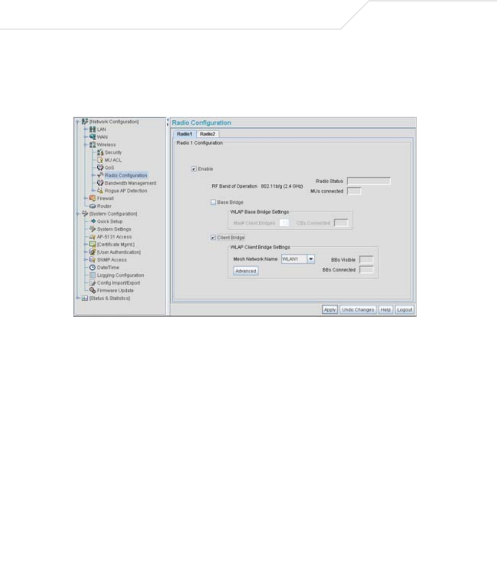
AP-51xx Access Point Product Reference Guide
9-42
22. The IT team selects Network Configuration -> Wireless -> Radio Configuration from
the AP-5131 menu tree.
The Radio Configuration screen displays.
23. For both AP5 and AP6, the IT Team enables Radio 1 and defines the radio as a client bridge.
24. For both AP5 and AP6, the IT Team uses the Mesh Network Name drop-down menu to
assign the “trion mesh” WLAN to radio 1.
25. As with APs 1-4, the IT Team decides to not select the Advanced button within the WLAP
Client Bridge Settings field.
26. The Trion IT Team clicks Apply within both the AP5 and AP6 Radio Configuration screens to
complete the mesh network configuration of each AP5 and AP6 radio.
For the foreseeable future, the Trion Enterprises’ mesh network will consist of APs 1-6. AP1
remains the root bridge in the mesh network. If the physical radio coverage area
requirements of the mesh network were to grow, AP5 and AP6 would have to be changed
from client bridges to repeaters to associate with the new APs required to extent the
coverage area. But for now, the 802.11a radio of both AP5 and AP6 can remain defined as a
client bridge to support the outer fringes of the Trion Enterprises shipping yard.


AP-51xx Access Point Product Reference Guide
A-2
A.1 Physical Characteristics
A.1.1 AP-5131 Physical Characteristics
The AP-5131 has the following physical characteristics:
Dimensions 5.32 inches long x 9.45 inches wide x 1.77 inches thick.
135 mm long x 240 mm wide x 45 mm thick.
Housing Metal, Plenum Housing (UL2043)
Weight 1.95 lbs/0.88 Kg (single-radio model)
2.05 lbs/0.93 Kg (dual-radio model)
Operating
Temperature
-20 to 50° Celsius
Storage Temperature -40 to 70° Celsius
Altitude 8,000 feet/2438 m @ 28° Celsius (operating)
15,000 feet/4572 m @ 12° Celsius (storage)
Vibration Vibration to withstand .02g²/Hz, random, sine, 20-2k Hz
Humidity 5 to 95% (operating) 5 to 85% (storage)
Electrostatic
Discharge
15kV (air) @ 50% rh
8kV (contact) @ 50% rh
Drop Bench drop 36 inches to concrete (excluding side with connectors)

Technical Specifications A-3
A.1.2 AP-5181 Physical Characteristics
The AP-5181 has the following physical characteristics:
Dimensions TBD
Housing TBD
Weight TBD
Operating
Temperature
30 to 55° Celsius
Storage Temperature 40 to 85° Celsius
Altitude 8,000 feet/2438 m @ 28° Celsius (operating)
15,000 feet/4572 m @ 12° Celsius (storage)
Vibration Vibration to withstand .02g²/Hz, random, sine, 20-2k Hz
Humidity 5 to 95% (operating) 5 to 95% (storage)
Electrostatic
Discharge
15kV (air) @ 50% rh
8kV (contact) @ 50% rh
Drop Bench drop 36 inches to concrete
Wind Blown Rain 40 MPH @ 0.1inch/minute, 15 minutes
Rain/Drip/Spill IPX5 Spray @ 4L/minute, 10 minutes
Dust IP6X 20mb vacuum max, 2 hours, stirred dust,
.88g/m^3 concentration @ 35%RH

AP-51xx Access Point Product Reference Guide
A-4
A.2 Electrical Characteristics
Both the AP-5131 and the AP-5181 access points have the following electrical characteristics:
A.3 Radio Characteristics
The AP-5131 and AP-5181 access points have the following radio characteristics:
CAUTION An AP-5181 model access point cannot use the AP-5131
recommended Symbol 48-Volt Power Supply (Part No. 50-24000-050).
However, Symbol does recommend the AP-PSBIAS-5181-01R model
power supply for use the AP-5181.
Operating Voltage 48Vdc (Nom)
Operating Current 200mA (Peak) @ 48Vdc
170mA (Nom) @ 48Vdc
Operating Channels 802.11a radio - Channels 34-161 (5170-5825 MHz)
802.11b/g radio - Channels 1-13 (2412-2472 MHz)
802.11b/g radio - Channel 14 (2484 MHz Japan only)
Actual operating frequencies depend on regulatory rules and
certification agencies.
Receiver Sensitivity 802.11a Radio 802.11b/g Radio
6 Mbps -88 11 Mbps -84
9 Mbps -87 5.5 Mbps -88
12 Mbps -85 2 Mbps -90
18 Mbps -81 1 Mbps -94
24 Mbps -79
36 Mbps -75
48 Mbps -70
54 Mbps -68
* all values in dBm
!

Technical Specifications A-5
A.4 Antenna Specifications
The antenna suite differs between the AP-5131 and AP-5181 model access points. Ensure your have
selected the correct model antenna before deploying the access point. For more information, see:
•AP-5131 Antenna Specifications
•AP-5181 Antenna Specifications
A.4.1 AP-5131 Antenna Specifications
A.4.1.1 2.4 GHz Antenna Matrix
The following table describes each 2.4 GHz antenna approved for use with the AP-5131.
A.4.1.2 5.2 GHz Antenna Matrix
The following table describes each 5.2 GHz antenna approved for use with the AP-5131.
Radio Data Rates 802.11a radio 6, 9, 12, 18, 24, 36, 48, and 54 Mbit/Sec
802.11g radio 6, 9, 12, 18, 24, 36, 48, and 54 Mbit/Sec
802.11b radio 1, 2, 5.5, 11 Mbps
Wireless Medium Direct Sequence Spread Spectrum (DSSS)
Orthogonal Frequency Division Multiplexing (OFDM)
CAUTION Using an antenna other than the Dual-Band Antenna (Part No.
ML-2452-APA2-01) could render the AP-5131’s Rogue AP Detector
Mode feature inoperable. Contact your Symbol sales associate for
specific information.
Symbol Part Number Antenna Type Nominal Net Gain (dBi)
ML-2499-11PNA2-01R Wide Angle Directional 8.5
ML-2499-HPA3-01R Omni-Directional Antenna 3.3
ML-2499-BYGA2-01R Yagi Antenna 13.9
ML-2452-APA2-01 Dual-Band 3.0
!

AP-51xx Access Point Product Reference Guide
A-6
A.4.1.3 AP-5131 Additional Antenna Components
The following table lists the Symbol part number for various antenna accessories. This table also
includes the loss for each accessory at both 2.4 and 5.2 GHz.
A.4.1.4 AP-5131 Antenna Accessory Connectors, Cable Type and Length
The following table describes each antenna accessory’s connector and cable type, plus the length.
Symbol Part Number Antenna Type Nominal Net Gain (dBi)
ML-5299-WPNA1-01R Panel Antenna 13.0
ML-5299-HPA1-01R Wide-Band Omni-Directional
Antenna
5.0
ML-2452-APA2-01 Dual-Band 4.0
Item Symbol Part Number Description
Loss (db)
@ 2.4 GHz
Loss (db)
@ 5.2 GHz
72PJ ML-1499-72PJ-01R Cable Extension 2.5
LAK1 ML-1499-LAK1-01R Lightning
Arrestor+
0.75
LAK2 ML-1499-LAK2-01R Lightning Arrestor 0.25
10JK ML-1499-10JK-01R Jumper Kit 0.75 1.6
25JK ML-1499-25JK-01R Jumper Kit 1.9 3.5
50JK ML-1499-50JK-01R Jumper Kit 3.75 6.6
100JK ML-1499-100JK-01R Jumper Kit 7.5 12.8
Item Connector1 Connector2 Length (meters) Cable Type
72PJ RPBNC-F RPBNC-M 1.83 RG-58
LAK1 RPBNC-F N-F 0.305 RG-58
LAK2 N-F N-M
10JK N-M N-M 3.05 RG-8

Technical Specifications A-7
A.4.2 AP-5181 Antenna Specifications
TBD
A.5 Country Codes
The following list of countries and their country codes is useful when using the access point
configuration file, CLI or the MIB to configure the access point:
25JK N-M N-M 7.62 RG-8
50JK N-M N-M 15.24 RG-8
100JK N-M N-M 30.48 RG-8
Country Code Country Code
Argentina AR New Zealand NZ
Australia AU Norway NO
Austria AT Oman OM
Bahrain BH Peru PE
Belarus BY Philippines PH
Belgium BE Poland PL
Brazil BR Portugal PT
Bulgaria BG Qatar QA
Canada CA Romania RO
Chile CL Russian Federation RU
China CN Saudi Arabia SA
Colombia CO Singapore SG
Costa Rica CR Slovak Republic SK
Croatia HR Slovenia SI
Cypress CY South Africa ZA
Item Connector1 Connector2 Length (meters) Cable Type

AP-51xx Access Point Product Reference Guide
A-8
Czech Rep. CZ South Korea KR
Denmark DK Spain ES
Ecuador EC Sri Lanka LK
Estonia EE Sweden SE
Egypt EG Switzerland CH
Finland FI Taiwan TW
France FR Thailand TH
Germany DE Turkey TR
Greece GR Ukraine UA
Hong Kong HK UAE AE
Hungary HU United Kingdom UK
Iceland IS USA US
India IN Uruguay UY
Indonesia ID Vietnam VN
Ireland IE Venezuela VE
Israel IL
Italy IT
Japan JP
Jordan JO
Kazakhanstan KZ
Kuwait KW
Latvia LV
Liechtenstein LI
Lithuania LT
Luxembourg LU
Malaysia MY
Malta MT

Technical Specifications A-9
Mexico MX
Morocco MA
Nambia NA
Netherlands NL

AP-51xx Access Point Product Reference Guide
A-10

Usage Scenarios
This appendix provides practical usage scenarios for many of the access point’s key features. This
information should be referenced as a supplement to the information contained within this access
point Product Reference Guide.
The following scenarios are described:
•Configuring Automatic Updates using a DHCP or Linux BootP Server Configuration
•Configuring an IPSEC Tunnel and VPN FAQs
B.1 Configuring Automatic Updates using a DHCP or Linux
BootP Server Configuration
This section provides specific details for configuring either a DHCP or Linux BootP Server to receive
firmware or configuration file updates from an access point.

AP-51xx Access Point Product Reference Guide
B-2
B.1.1 Windows - DHCP Server Configuration
See the following sections for information on these DHCP server configurations in the Windows
environment:
•Embedded Options - Using Option 43
•Global Options - Using Extended/Standard Options
•DHCP Priorities
B.1.1.1 Embedded Options - Using Option 43
This section provides instructions for automatic update of firmware and configuration file via DHCP
using extended options or standard options configured globally.
The setup example described in this section includes:
• 1 AP-5131 or AP-5181 model access point
• 1 Microsoft Windows DHCP Server
• 1 TFTP Server
Note the following caveats regarding this procedure before beginning:
• Ensure the LAN Interface is configured as a DHCP Client
• If the existing and update firmware files are the same, the firmware will not get updated.
To configure the DHCP Server for automatic updates:
1. Set the Windows DHCP Server and access point on the same Ethernet segment.
2. Configure the Windows based DHCP Server as follows:
a. Highlight the Server Domain Name (for example, apfw.symbol.com). From the Action
menu, select Define Vendor Classes.
b. Create a new vendor class. For example, AP5131 Options.
c. Enter the Vendor Class Identifier SymbolAP.5131-V1-0. Enter the value in ASCII format,
the server converts it to hex automatically.
d. From the Action menu, select Set Predefined Options.

Usage Scenarios B-3
e. Add the following 3 new options under AP5131 Options class:
f. Highlight Scope Options from the tree and select Configure Options.
g. Go to the Advanced tab. From under the Vendor Class Options, check all three options
mentioned in the table above and enter a value for each option.
3. Copy the firmware and configuration files to the appropriate directory on the TFTP Server.
By default, the auto update is enabled on the WAN Port (has to be DHCP Client).
4. Restart the access point.
5. While the access point boots, verify the access point:
• Obtains and applies the expected IP Address from the DHCP Server
• Downloads both the firmware and configuration files from the TFTP Server and updates
both as needed.
• Verify the file versions from the access point’s System Settings screen.
B.1.1.2 Global Options - Using Extended/Standard Options
The following are instructions for automatic firmware and configuration file updates via DHCP using
extended options or standard options configured globally.
The setup example described in this section includes:
• 1 AP-5131 or AP-5181 model access point
• 1 Microsoft Windows DHCP Server
• 1 TFTP Server.
Note the following caveats regarding this procedure before beginning:
• For updates using the LAN Port, change the interface on the Firmware Update screen from
WAN to LAN. Also ensure the LAN Interface is configured as a DHCP Client
• If the existing and update firmware files are the same, the firmware will not get updated.
Code Data type
Access point TFTP Server IP Address
(Note: Use any one option)
181
186
IP address
String
Access point Firmware File Name 187 String
Access point Config File Name
(Note: Use any one option)
129
188
String
String
AP-51xx Access Point Product Reference Guide
B-4
To configure Global options using extended/standard options:
1. Set the Windows DHCP Server and access point on the same Ethernet segment.
2. Configure the Windows based DHCP Server as follows:
a. Highlight the Server Domain Name (for example, apfw.symbol.com). From the Action
menu, select Set Predefined Options.
b. Add the following 3 new options under DHCP Standard Options class:
c. Highlight Scope Options and select Configure Options.
d. Under the General tab, check all 3 options mentioned within the Extended Options table
and enter a value for each option.
3. Copy both the firmware and configuration files to the appropriate directory on the TFTP
Server.
4. Restart the access point.
5. While the access point boots up, verify the access point:
• Obtains and applies the expected IP Address from the DHCP Server
• Downloads the firmware and configuration files from the TFTP Server and updates both
as required.
Extended Options Code Data type
Access point TFTP Server IP Address
(Note: Use any one option)
181
186
IP address
String
Access Point Firmware File Name 187 String
Access Point Config File Name
(Note: Use any one option)
129
188
String
String
Standard Options Code Data type
Access point TFTP Server IP Address 66 String
Access point Firmware File Name 67 String
NOTE If using Standard Options and the configuration of the access point needs
to be changed, use option 129 or 188 as specified in Extended Options
table. Standard options 66 and 67 are already present in the DHCP
Standard Options Class by default.
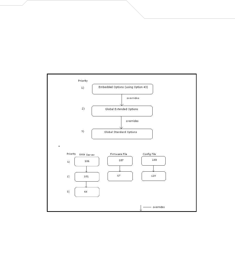
Usage Scenarios B-5
• Verify the file versions within the access point’s System Settings screen.
B.1.1.3 DHCP Priorities
The following flowchart indicates the priorities used by the access point when the DHCP server is
configured for options.
If the DHCP Server is configured for options 186 and 66 (to assign TFTP Server IP addresses) the
access point uses the IP address configured for option 186. Similarly, if the DHCP Server is configured
for options 187 and 67 (for the firmware file) the access point uses the file name configured for option
187. If the DHCP Server is configured for embedded and global options, the embedded options take
precedence.
--------------------------------------------------------------------------------------------

AP-51xx Access Point Product Reference Guide
B-6
B.1.2 Linux - BootP Server Configuration
See the following sections for information on these BootP server configurations in the Linux
environment:
•BootP Options
•BootP Priorities
B.1.2.1 BootP Options
This section contains instructions for the automatic update of the access point firmware and
configuration file using a BootP Server.
The setup example described in this section includes:
• 1 AP-5131 or AP-5181 model access point
• 1 Linux/Unix BOOTP Server
• 1 TFTP Server.
Please note the following caveats regarding this procedure before beginning:
• The LAN Port needs to be configured as a BootP client.
• No BootP support is available on the WAN Port.
• If the existing and update firmware files are the same, the firmware will not get updated.
To configure BootP options using a Linux/Unix BootP Server:
1. Set the Linux/Unix BootP Server and access point on the same Ethernet segment.
2. Configure the bootptab file (/etc/bootptab) on the Linux/Unix BootP Server in any one of the
formats that follows:
Using options 186, 187 and 188:
AP-5131:ha=00a0f88aa6d8\ < LAN MAC Address>
:sm =255.255.255.0\ <Subnet Mask>
:ip=157.235.93.128\ <IP Address>
:gw=157.235.93.2\ <gateway>
:T186=”157.235.93.250”\ <TFTP Server IP>
:T187="apfw .bin"\ <Firmware file>
:T188="cfg.txt": <Configuration file>

Usage Scenarios B-7
Using options 66, 67 and 129:
Using options sa, bf and 136:
3. Copy the firmware and configuration files to the appropriate directory on the TFTP Server.
This has to be changed to the LAN Port. Additionally, the LAN Interface needs to be
configured as a BootP Client.
4. Restart the access point.
5. While the access point boots, verify the access point:
• Obtains and applies the expected IP Address from the BootP Server.
• Downloads both the firmware and configuration files from the TFTP Server and updates
them as required. Verify the file versions within the access point System Settings
screen.
NOTE bf option prefixes a forward slash (/) to the firmware file name. This may
not be supported on Windows based TFTP Servers.
AP-5131:ha=00a0f88aa6d8\ < LAN M AC Address>
:sm =255.255.255.0\ <Subnet Mask>
:ip=157.235.93.128\ <IP Address>
:gw =157.235.93.2\ <gatew ay>
:T66=”157.235.93.250”\ <TFTP Server IP>
:T67="apfw .bin"\ <Firmware file>
:T129="cf
g
.txt": <Confi
g
uration file>
AP-5131:ha=00a0f88aa6d8\ < LAN MAC Address>
:sm=255.255.255.0\ <Subnet Mask>
:ip=157.235.93.128\ <IP Address>
:gw=157.235.93.2\ <gateway>
:sa=157.235.93.250\ <TFTP Server IP>
:bf=/tftpboot/cfg.txt\ <Configuration file>
:T136=”/tftpboot/”: <TFTP root directory>
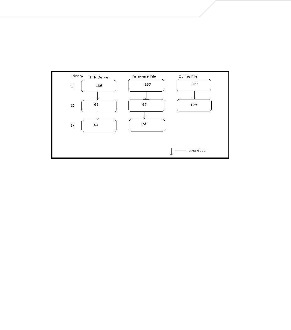
AP-51xx Access Point Product Reference Guide
B-8
B.1.2.2 BootP Priorities
The following flowchart displays the priorities used by the access point when the BootP server is
configured for multiple options:
If the BootP Server is configured for options 186 and 66 (to assign TFTP server IP addresses) the
access point uses the IP address configured for option 186. Similarly, if the BootP Server is configured
for options 188 and 129 (for the configuration file) the access point uses the file name configured for
option 188.
B.2 Configuring an IPSEC Tunnel and VPN FAQs
The access point has the capability to create a tunnel between an access point and a VPN endpoint.
The access point can also create a tunnel from one access point to another access point.
The following instruction assumes the reader is familiar with basic IPSEC and VPN terminology and
technology.
•Configuring a VPN Tunnel Between Two Access Points
•Configuring a Cisco VPN Device
•Frequently Asked VPN Questions
B.2.1 Configuring a VPN Tunnel Between Two Access Points
The access point can connect to a non-AP device supporting IPSec, such as a Cisco VPN device -
labeled as "Device #2".
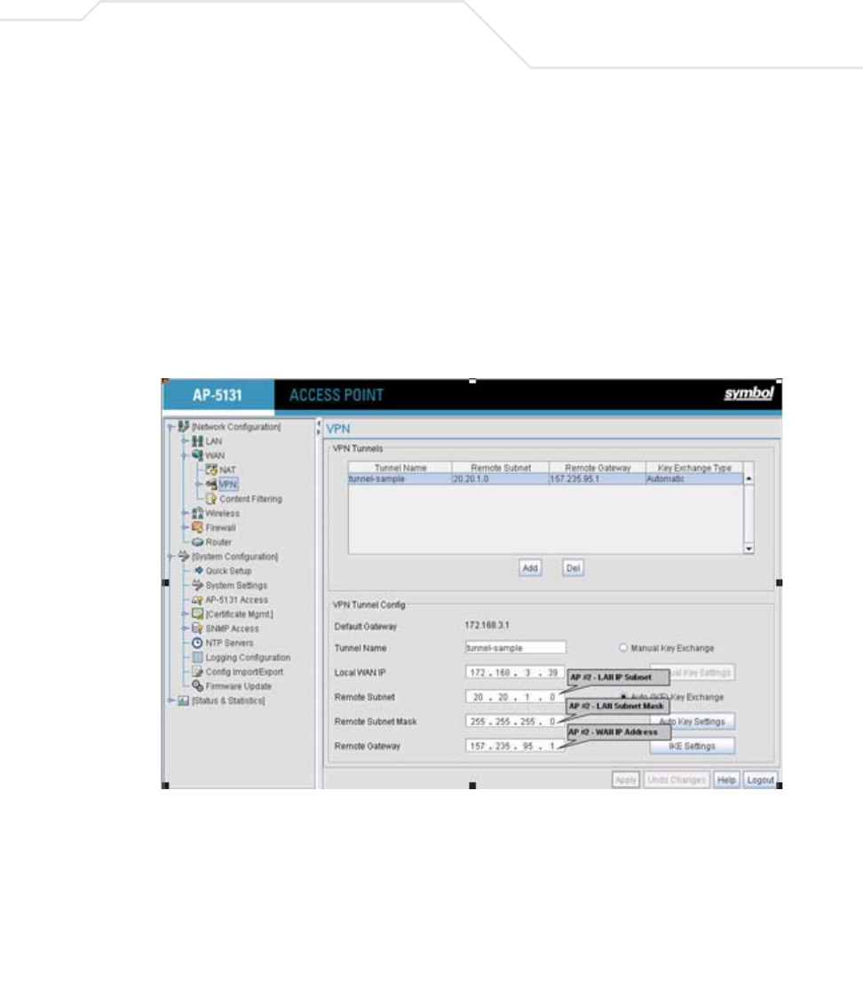
Usage Scenarios B-9
For this usage scenario, the following components are required:
• 2 AP-5131 or AP-5181 model access points
• 1 PC on each side of the access point’s LAN.
To configure a VPN tunnel between two access points:
1. Ensure the WAN ports are connected via the internet.
2. On access point #1, select WAN -> VPN from the main menu tree.
3. Click Add to add the tunnel to the list.
4. Enter a tunnel name (tunnel names do not need to match).
5. Enter the WAN port IP address of AP #1 for the Local WAN IP.
6. Within the Remote Subnet and Remote Subnet Mask fields, enter the LAN IP subnet and
mask of AP #2 /Device #2.
7. Enter the WAN port IP address of AP #2/ Device #2 for a Remote Gateway.
8. Click Apply to save the changes.
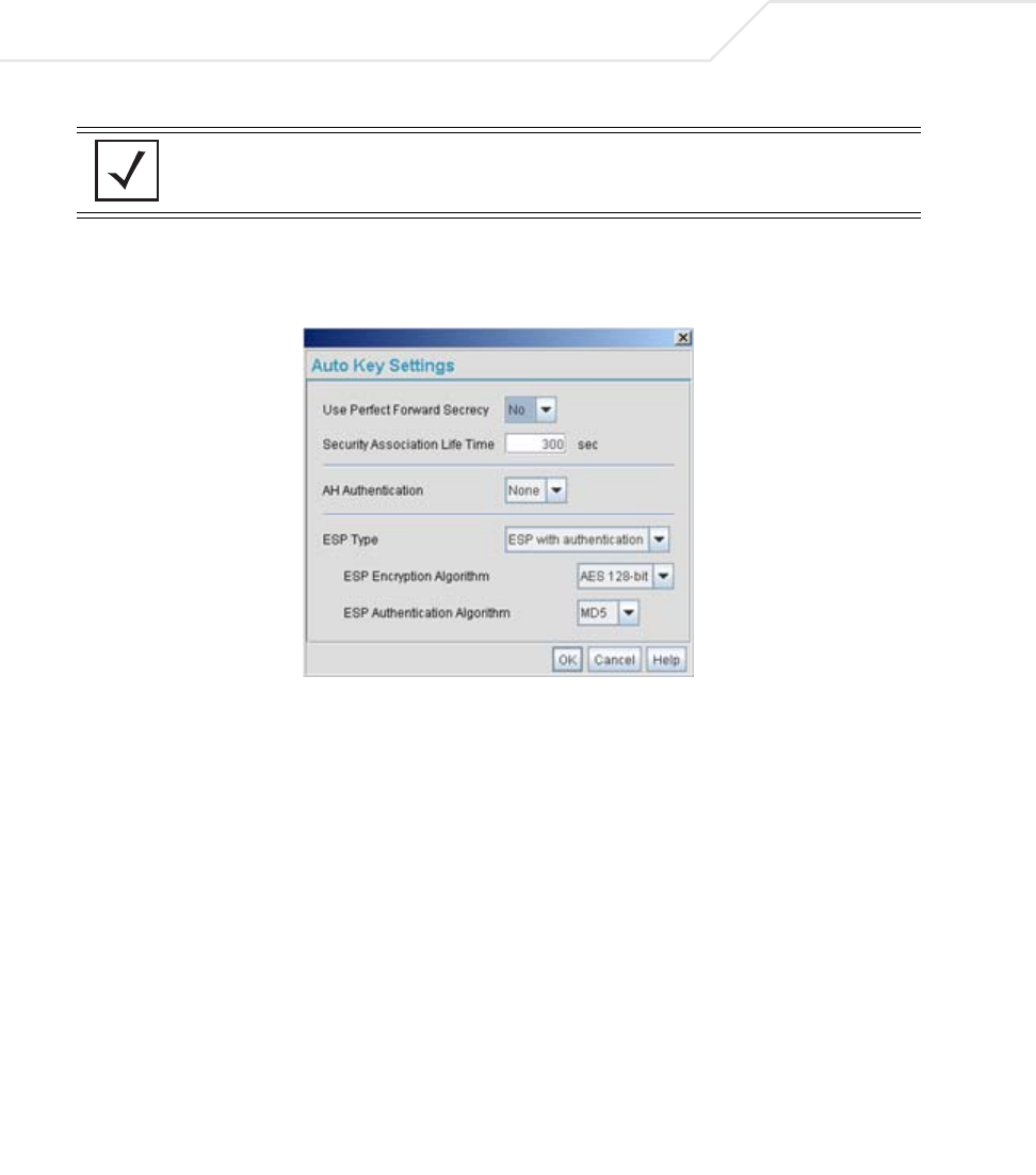
AP-51xx Access Point Product Reference Guide
B-10
9. Select the Auto (IKE) Key Exchange checkbox.
10. Select the Auto Key Settings button.
11. For the ESP Type, select ESP with Authentication and use AES 128-bit as the ESP
Encryption Algorithm. Click OK.
12. Select the IKE Settings button.
NOTE For this example, Auto IKE Key Exchange is used. Any key exchange can
be used, depending on the security needed, as long as both devices on
each end of the tunnel are configured exactly the same.
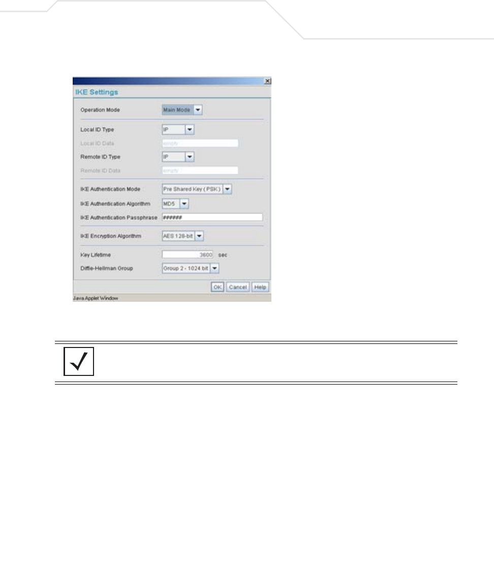
Usage Scenarios B-11
13. Select Pre Shared Key (PSK) from the IKE Authentication Mode drop-down menu.
14. Enter a Passphrase. Passphrases must match on both VPN devices.
15. Select AES 128-bit as the IKE Encryption Algorithm.
16. Select Group 2 as the Diffie -Hellman Group. Click OK. This will take you back to the VPN
screen.
17. Click Apply to make the changes
18. Check the VPN Status screen. Notice the status displays "NOT_ACTIVE". This screen
automatically refreshes to get the current status of the VPN tunnel. Once the tunnel is
active, the IKE_STATE changes from NOT_CONNECTED to SA_MATURE.
NOTE Ensure the IKE authentication Passphrase is the same as the Pre-shared
key on the Cisco PIX device.
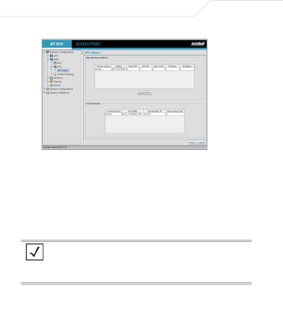
AP-51xx Access Point Product Reference Guide
B-12
19. On access point #2/ Device #2, repeat the same procedure. However, replace access point
#2 information with access point #1 information.
20. Once both tunnels are established, ping each side of the tunnel to ensure connectivity.
B.2.2 Configuring a Cisco VPN Device
This section includes general instructions for configuring a Cisco PIX Firewall 506 series device.
For the usage scenario described in this section, you will require the following:
• 1 Cisco VPN device
• 1 PC connected to the LAN side of the access pointand the Cisco PIX.
Below is how the access point VPN Status screen should look if the entire configuration is setup
correctly once the VPN tunnel is active. The status field should display "ACTIVE".
NOTE The Cisco PIX device configuration should match the access point VPN
configuration in terms of Local WAN IP (PIX WAN), Remote WAN
Gateway (access point WAN IP), Remote Subnet (access point LAN
Subnet), and the Remote Subnet Mask. The Auto Key Settings and the IKE
Settings on the Cisco PIX should match the access point Key and IKE
settings.
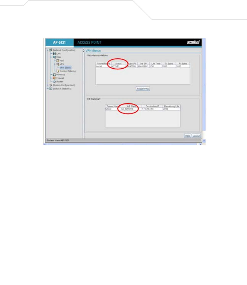
Usage Scenarios B-13
B.2.3 Frequently Asked VPN Questions
The following are common questions that arise when configuring a VPN tunnel using the access
point.
• Question 1: Does the access point IPSec tunnel support multiple subnets on the
other end of a VPN concentrator?
Yes. The access point can access multiple subnets on the other end of the VPN Concentrator
from the access point's Local LAN Subnet by:
• Creating multiple VPN Tunnels. The AP supports a maximum of 25 tunnels.
• When using the Remote Subnet IP Address with an appropriate subnet mask, the AP can
access multiple subnets on the remote end.
For example: If creating a tunnel using 192.168.0.0/16 for the Remote Subnet IP address, the
following subnets could be accessed:
192.168.1.x
192.168.2.x
192.168.3.x, etc
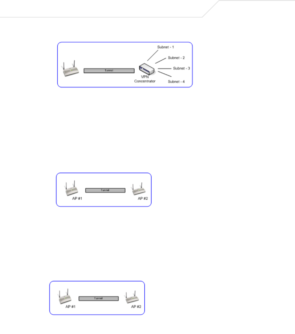
AP-51xx Access Point Product Reference Guide
B-14
•Question 2: Even if a wildcard entry of "0.0.0.0" is entered in the Remote Subnet
field in the VPN configuration page, can the AP access multiple subnets on the
other end of a VPN concentrator for the APs LAN/WAN side?
No. Using a "0.0.0.0" wildcard is an unsupported configuration. In order to access multiple
subnets, the steps in Question #1 must be followed.
• Question 3: Can the AP be accessed via its LAN interface of AP#1 from the local
subnet of AP#2 and vice versa?
Yes.
• Question 4: Will the default "Manual Key Exchange" settings work without making
any changes?
No. Changes need to be made. Enter Inbound and Outbound ESP Encryption keys on both
APs. Each one should be of 16 Hex characters (depending on the encryption or
authentication scheme used). The VPN tunnel can be established only when these
corresponding keys match. Ensure the Inbound/Outbound SPI and ESP Authentication Keys
have been properly specified.
• Question 5: Can a tunnel between an access point and a WS2000 be established?
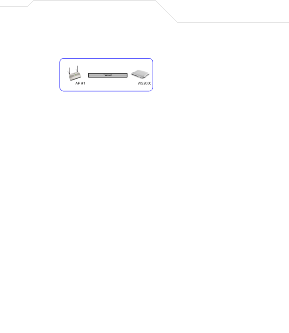
Usage Scenarios B-15
Yes.
• Question 6: Can an IPSec tunnel over a PPPoE connection be established - such as
a PPPoE enabled DSL link?
Yes. The access point supports tunneling when using a PPPoE username and password.
• Question 7: Can I setup an access point so clients can access both the WAN
normally and only use the VPN when talking to specific networks?
Yes. Only packets that match the VPN Tunnel Settings will be sent through the VPN tunnel.
All other packets will be handled by whatever firewall rules are set.
• Question 8: How do I specify which certificates to use for an IKE policy from the
access point certificate manager?
When generating a certificate to use with IKE, use one of the following fields: IP address,
Domain Name, or Email address. Also, make sure you are using NTP when attempting to
use the certificate manager. Certificates are time sensitive.
Configure the following on the IKE Settings page:
Local ID type refers to the way that IKE selects a local certificate to use.
• IP - tries the match the local WAN IP to the IP addresses specified in a local certificate.
• FQDN - tries to match the user entered local ID data string to the domain name field of
the certificate.
• UFQDN - tries to match the user entered local ID data string to the email address field
of the certificate.
Remote ID type refers to the way you identify an incoming certificate as being associated
with the remote side.
• IP - tries the match the remote gateway IP to the IP addresses specified in the received
certificate.
• FQDN - tries to match the user entered remote ID data string to the domain name field
of the received certificate.

AP-51xx Access Point Product Reference Guide
B-16
• UFQDN - tries to match the user entered remote ID data string to the email address field of
the received certificate.
• Question 9: I am using a direct cable connection between my two VPN gateways
for testing and cannot get a tunnel established, yet it works when I set them up
across another network or router. Why?
The packet processing architecture of the access point VPN solution requires the WAN
default gateway to work properly. When connecting two gateways directly, you don't need
a default gateway when the two addresses are on the same subnet. As a workaround, point
the access point's WAN default gateway to be the other VPN gateway and vice-versa.
• Question 10: I have setup my tunnel and the status still says 'Not Connected'. What
should I do now?
VPN tunnels are negotiated on an "as-needed" basis. If you have not sent any traffic
between the two subnets, the tunnel will not get established. Once a packet is sent between
the two subnets, the VPN tunnel setup occurs.

Usage Scenarios B-17
• Question 11: I still can't get my tunnel to work after attempting to initiate traffic
between the two subnets. What now?
Try the following troubleshooting tips:
• Verify you can ping each of the remote Gateway IP addresses from clients on either side.
Failed pings can indicate general network connection problems.
• Pinging the internal gateway address of the remote subnet should run the ping through
the tunnel as well. Allowing you to test, even if there are no clients on the remote end.
• Question 12: My tunnel works fine when I use the LAN-WAN Access page to
configure my firewall. Now that I use Advanced LAN Access, my VPN stops
working. What am I doing wrong?
VPN requires certain packets to be passed through the firewall. Subnet Access
automatically inserts these rules for you when you do VPN. Advanced Subnet Access
requires these rules to be in effect for each tunnel.
• An 'allow' inbound rule.
• An 'allow' outbound rule.
• For IKE, an 'allow' inbound rule.
Scr <Remote Subnet IP range>
Dst <Local Subnet IP range>
Transport ANY
Scr port 1:65535
Dst port 1:65535
Rev NAT None
Scr <Local Subnet IP range>
Dst <Remote Subnet IP range>
Transport ANY
Scr port 1:65535
Dst port 1:65535
NAT None

AP-51xx Access Point Product Reference Guide
B-18
These three rules should be configured above all other rules (default or user defined). When
Advanced LAN Access is used, certain inbound/outbound rules need to be configured to
control incoming/outgoing packet flow for IPSec to work properly (with Advanced LAN
Access). These rules should be configured first before other rules are configured.
• Question 13: Do I need to add any special routes on the access point to get my VPN
tunnel to work?
No. However, clients could need extra routing information. Clients on the local LAN side
should either use the access point as their gateway or have a route entry tell them to use
the access point as the gateway to reach the remote subnet.
B.3 Replacing an AP-4131 with an AP-5131 or AP-5181
The access point’s modified default configuration enables an access point to not only operate in a
single-cell environrment, but also function as a replacement for legacy Symbol AP-4131 model access
points. You cannot port an access point’s configuration file to an access point, but you can configure
an access point similarly and provide an improved data rate and feature set.
An AP-4131 has only one LAN port and it is defaulted to DHCP/BOOTP enabled. The access point is
optimized for single-cell deployment, so it should allow the customer to use an access point as a
”drop-in” replacement for an existing AP-4131 deployment. However, to optimally serve as a
replacement for existing AP-4131 deployments, the access point’s “out-of-box” defaults are now set
as follows:
• The access point’s LAN1 port must default to DHCP client mode
• The access point’s LAN2 port must default to DHCP server mode
• The access point’s WAN port must default to Static mode.
• The default gateway now defaults to LAN1.
Scr <Remote Subnet IP range>
Dst <WAN IP address>
Transport UDP
Scr port 1:65535
Dst port 500
Rev NAT None

Usage Scenarios B-19
• The interface parameter has been removed from the Auto Update configuration feature.
• The WAN interface now has http/telnet/https/ssh connectivity enabled by default.

AP-51xx Access Point Product Reference Guide
B-20

Customer Support
Symbol Technologies provides its customers with prompt and accurate customer support. Use the
Symbol Support Center as the primary contact for any technical problem, question or support issue
involving Symbol products.
If the Symbol Customer Support specialists cannot solve a problem, access to all technical disciplines
within Symbol becomes available for further assistance and support. Symbol Customer Support
responds to calls by email, telephone or fax within the time limits set forth in individual contractual
agreements.
When contacting Symbol Customer Support, please provide the following information:
• serial number of unit
• model number or product name
• software type and version number.

AP-51xx Access Point Product Reference Guide
C-2
North American Contacts
Inside North America:
Symbol Technologies, Inc.
One Symbol Plaza Holtsville, New York 11742-1300
Telephone: 1-631-738-2400/1-800-SCAN 234
Fax: 1-631-738-5990
Symbol Support Center (for warranty and service information):
telephone: 1-800-653-5350
fax: (631) 738-5410
Email: support@symbol.com
International Contacts
Outside North America:
Symbol Technologies
Symbol Place
Winnersh Triangle, Berkshire, RG41 5TP
United Kingdom
0800-328-2424 (Inside UK)
+44 118 945 7529 (Outside UK)

Customer Support C-3
Web Support Sites
MySymbolCare
http://www.symbol.com/services/msc/msc.html
Symbol Services Homepage
http://symbol.com/services
Manual Updates
http://symbol.com/legacy_manuals/wire/accesspoints.html
Symbol Developer Program
http://devzone.symbol.com
Additional Information
Obtain additional information by contacting Symbol at:
1-800-722-6234, inside North America
+1-516-738-5200, in/outside North America
http://www.symbol.com/

AP-51xx Access Point Product Reference Guide
C-4

Numerics
2.4 GHz antennas. . . . . . . . . . . . . . . . . . . . . . . . . . . . . . A-5
32735
Heading 2
1.1.11 Symbol NetVision Phone/Spectralink
Voice Prioritization. . . . . . . . . . . . . . . . . . . . . . . . . . . . 1-17
A
access options . . . . . . . . . . . . . . . . . . . . . . . . . . . . . . . 1-25
Access Point
CAM . . . . . . . . . . . . . . . . . . . . . . . . . . . . . . . . . . 1-17
encryption . . . . . . . . . . . . . . . . . . . . . . . . . . . . . . 1-12
PSP . . . . . . . . . . . . . . . . . . . . . . . . . . . . . . . . . . . 1-17
RSSI. . . . . . . . . . . . . . . . . . . . . . . . . . . . . . . . . . . 1-23
addresses, Symbol. . . . . . . . . . . . . . . . . . . . . . . . . . . . . .viii
administrator access . . . . . . . . . . . . . . . . . . . . . . . . . . . 4-8
antenna support. . . . . . . . . . . . . . . . . . . . . . . . . . . . . . . 1-8
antenna, 2.4 GHz . . . . . . . . . . . . . . . . . . . . . . . . . . . . . . A-5
AP-5131 access . . . . . . . . . . . . . . . . . . . . . . . . . . . . . . . 4-5
AP-5131 Features. . . . . . . . . . . . . . . . . . . . . . . . . . . . . . 1-6
AP-5131 Firmware . . . . . . . . . . . . . . . . . . . . . . . . . . . . 1-15
AP-5131 management options. . . . . . . . . . . . . . . . . . . 1-15
AP-5131 operating modes . . . . . . . . . . . . . . . . . . . . . . 1-24
AP-5131 placement . . . . . . . . . . . . . . . . . . . . . . . . . . . . 2-5
AP-5131 statistical displays. . . . . . . . . . . . . . . . . . . . . 1-17
AP-5131 version . . . . . . . . . . . . . . . . . . . . . . . . . . . . . . . 4-3
AP-5131-13040-WW . . . . . . . . . . . . . . . . . . . . . . . . . . . 2-2
AP-5131-13041-WW . . . . . . . . . . . . . . . . . . . . . . . . . . . 2-2
AP-5131-13042-WW . . . . . . . . . . . . . . . . . . . . . . . . . . . 2-2
AP-5131-13043-WW . . . . . . . . . . . . . . . . . . . . . . . . . . . 2-3
AP-5131-40020-WW . . . . . . . . . . . . . . . . . . . . . . . . . . . 2-3
AP-5131-40021-WW . . . . . . . . . . . . . . . . . . . . . . . . . . . 2-3
AP-5131-40022-WW . . . . . . . . . . . . . . . . . . . . . . . . . . . 2-3
AP-5131-40023-WW . . . . . . . . . . . . . . . . . . . . . . . . . . . 2-3
association process
beacon. . . . . . . . . . . . . . . . . . . . . . . . . . . . . . . . . 1-17
RSSI. . . . . . . . . . . . . . . . . . . . . . . . . . . . . . . . . . . 1-23
automatic firmware update . . . . . . . . . . . . . . . . . . . . . 4-43
available AP-5131 product configurations. . . . . . . . . . . 2-2
available protocols. . . . . . . . . . . . . . . . . . . . . . . . . . . . 6-30
Index

AP-5131 Access Point Product Reference Guide
IN-6
B
Bandwidth Management . . . . . . . . . . . . . . . . . . . . . . . 5-55
basic device configuration . . . . . . . . . . . . . . . . . . . . . . . 3-3
beacon. . . . . . . . . . . . . . . . . . . . . . . . . . . . . . . . . . . . . . 1-17
CAM stations . . . . . . . . . . . . . . . . . . . . . . . . . . . .1-17
PSP stations . . . . . . . . . . . . . . . . . . . . . . . . . . . . . 1-17
BSSID . . . . . . . . . . . . . . . . . . . . . . . . . . . . . . . . . . . . . . . 1-8
bullets, use of . . . . . . . . . . . . . . . . . . . . . . . . . . . . . . . . . viii
C
CA certificate . . . . . . . . . . . . . . . . . . . . . . . . . . . . . . . . . 4-8
CAM . . . . . . . . . . . . . . . . . . . . . . . . . . . . . . . . . . . . . . . 1-17
cellular coverage. . . . . . . . . . . . . . . . . . . . . . . . . . . . . . 1-20
certificate authority . . . . . . . . . . . . . . . . . . . . . . . . . . . .4-8
certificate management . . . . . . . . . . . . . . . . . . . . . . . . . 4-8
CLI, ACL commands . . . . . . . . . . . . . . . . . . . . . . . . . . . 8-80
CLI, bandwith management . . . . . . . . . . . . . . . . . . . . 8-107
CLI, common commands . . . . . . . . . . . . . . . . . . . . . . . . .8-3
CLI, connection . . . . . . . . . . . . . . . . . . . . . . . . . . . . . . . . 8-1
CLI, firewall commands . . . . . . . . . . . . . . . . . . . . . . .8-120
CLI, firmware update . . . . . . . . . . . . . . . . . . . . . . . . . 8-182
CLI, log commands . . . . . . . . . . . . . . . . . . . . . . . . . . . 8-169
CLI, network commands . . . . . . . . . . . . . . . . . . . . . . . .8-11
CLI, network LAN commands . . . . . . . . . . . . . . . . . . . . 8-12
CLI, network LAN, DHCP commands . . . . . . . . . . . . . . 8-28
CLI, network wireless commands. . . . . . . . . . . . . . . . . 8-57
CLI, NTP. . . . . . . . . . . . . . . . . . . . . . . . . . . . . . . . . . . .8-164
CLI, QoS. . . . . . . . . . . . . . . . . . . . . . . . . . . . . . . . . . . . 8-102
CLI, radio configuration. . . . . . . . . . . . . . . . . . . . . . . . .8-85
CLI, rogue-AP commands . . . . . . . . . . . . . . . . . . . . . . 8-110
CLI, router commands . . . . . . . . . . . . . . . . . . . . . . . . .8-125
CLI, security commands . . . . . . . . . . . . . . . . . . . . . . . .8-71
CLI, serial port. . . . . . . . . . . . . . . . . . . . . . . . . . . . . . . . . 8-1
CLI, SNMP access. . . . . . . . . . . . . . . . . . . . . . . . . . . . 8-153
CLI, SNMP commands . . . . . . . . . . . . . . . . . . . . . . . . 8-152
CLI, SNMP traps . . . . . . . . . . . . . . . . . . . . . . . . . . . . .8-158
CLI, statistics. . . . . . . . . . . . . . . . . . . . . . . . . . . . . . . . 8-186
CLI, system access commands . . . . . . . . . . . . . . . . . . 8-136
CLI, system commands . . . . . . . . . . . . . . . . . . . . . . . .8-131
CLI, telnet . . . . . . . . . . . . . . . . . . . . . . . . . . . . . . . . . . . . 8-2
CLI, type filter commands . . . . . . . . . . . . . . . . . . . . . . . 8-34
CLI, WAN commands . . . . . . . . . . . . . . . . . . . . . . . . . .8-39
CLI, WAN NAT commands . . . . . . . . . . . . . . . . . . . . . . 8-42
CLI, WAN VLAN Commands . . . . . . . . . . . . . . . . . . . . . 8-48
Command Line Interface (CLI)
configuration . . . . . . . . . . . . . . . . . . . . . . . . . . . .1-20
command line interface (CLI) . . . . . . . . . . . . . . . . . . . . .3-2
config file . . . . . . . . . . . . . . . . . . . . . . . . . . . . . . . . . . . .3-3
config import/export . . . . . . . . . . . . . . . . . . . . . . . . . . .4-36
configuration
CLI. . . . . . . . . . . . . . . . . . . . . . . . . . . . . . . . . . . . .1-20
configuration file import/export . . . . . . . . . . . . . . . . . .1-18
configuration options . . . . . . . . . . . . . . . . . . . . . . . . . . .3-2
configuration restoration . . . . . . . . . . . . . . . . . . . . . . .1-18
Content Filtering . . . . . . . . . . . . . . . . . . . . . . . . . . . . . .1-14
content filtering. . . . . . . . . . . . . . . . . . . . . . . . . . . . . . .6-49
conventions, notational. . . . . . . . . . . . . . . . . . . . . . . . . . viii
country codes . . . . . . . . . . . . . . . . . . . . . . . . . . . . . 4-3, A-7
customer support . . . . . . . . . . . . . . . . . . . . . . . . . . viii, B-1
D
data access, configuring . . . . . . . . . . . . . . . . . . . . . . . . .4-5
data decryption . . . . . . . . . . . . . . . . . . . . . . . . . . . . . . .1-12
data encryption . . . . . . . . . . . . . . . . . . . . . . . . . . . . . . .1-10
data security . . . . . . . . . . . . . . . . . . . . . . . . . . . . . . . . .1-10
Desk Mounting . . . . . . . . . . . . . . . . . . . . . . . . . . . . . . .2-12
device firmware . . . . . . . . . . . . . . . . . . . . . . . . . . . . . .4-40
device settings . . . . . . . . . . . . . . . . . . . . . . . . . . . . . . . .3-5
DHCP support . . . . . . . . . . . . . . . . . . . . . . . . . . . . . . . .1-19
DHCP, advanced settings . . . . . . . . . . . . . . . . . . . . . . .5-11
direct-sequence spread spectrum. . . . . . . . . . . . . . . . .1-22
Document Conventions . . . . . . . . . . . . . . . . . . . . . . . . . 1-vii
dual-radio sku . . . . . . . . . . . . . . . . . . . . . . . . . . . . . . . . .1-7
E
EAP . . . . . . . . . . . . . . . . . . . . . . . . . . . . . . . . . . . 1-10, 1-11
EAP authentication . . . . . . . . . . . . . . . . . . . . . . . . . . . .1-11
electrical characteristics. . . . . . . . . . . . . . . . . . . . . . . . A-4
event logging. . . . . . . . . . . . . . . . . . . . . . . . . . . . . . . . .1-18
F
firewall . . . . . . . . . . . . . . . . . . . . . . . . . . . . . . . . . . . . .1-14
Firewall Security . . . . . . . . . . . . . . . . . . . . . . . . . . . . . .1-14
firewall, configuring . . . . . . . . . . . . . . . . . . . . . . . . . . .6-25
firmware . . . . . . . . . . . . . . . . . . . . . . . . . . . . . . . . . . . .1-15
firmware update . . . . . . . . . . . . . . . . . . . . . . . . . . . . . .4-41
firmware, updates. . . . . . . . . . . . . . . . . . . . . . . . . . . . .4-40

IN-7
H
hardware installation. . . . . . . . . . . . . . . . . . . . . . . . . . . 2-1
I
importing certificates. . . . . . . . . . . . . . . . . . . . . . . . . . . 4-8
importing/exporting configurations . . . . . . . . . . . . . . . 4-36
installation, ceiling . . . . . . . . . . . . . . . . . . . . . . . . . . . 2-18
installation, ceiling T-Bar. . . . . . . . . . . . . . . . . . . . . . . 2-16
installation, desk mounting . . . . . . . . . . . . . . . . . . . . . 2-12
installation, wall mounting . . . . . . . . . . . . . . . . . . . . . 2-14
J
Java-Based WEB UI. . . . . . . . . . . . . . . . . . . . . . . . . . . . 3-2
K
Kerberos. . . . . . . . . . . . . . . . . . . . . . . . . . . . . . . .1-10, 1-11
authentication. . . . . . . . . . . . . . . . . . . . . . . . . . . 1-11
implementation. . . . . . . . . . . . . . . . . . . . . . . . . . 1-11
Kerberos authentication . . . . . . . . . . . . . . . . . . . . . . . 1-11
KeyGuard . . . . . . . . . . . . . . . . . . . . . . . . . . 1-10, 1-13, 6-18
L
LAN port. . . . . . . . . . . . . . . . . . . . . . . . . . . . . . . . . . . . . 1-7
LAN to WAN access . . . . . . . . . . . . . . . . . . . . . . . . . . 6-27
LAN, configuring . . . . . . . . . . . . . . . . . . . . . . . . . . . . . . 5-1
LAN, statistics . . . . . . . . . . . . . . . . . . . . . . . . . . . . . . . . 7-6
LAN, timeout . . . . . . . . . . . . . . . . . . . . . . . . . . . . . . . . . 5-2
LED indicators . . . . . . . . . . . . . . . . . . . . . . . . . . . . . . . 1-19
LEDs . . . . . . . . . . . . . . . . . . . . . . . . . . . . . . . . . . .1-19, 2-21
logging configuration . . . . . . . . . . . . . . . . . . . . . . . . . . 4-34
login screen . . . . . . . . . . . . . . . . . . . . . . . . . . . . . . .3-3, 4-1
M
MAC layer bridging . . . . . . . . . . . . . . . . . . . . . . . . . . . 1-21
management options . . . . . . . . . . . . . . . . . . . . . . . . . . 1-25
SNMP . . . . . . . . . . . . . . . . . . . . . . . . . . . . . . . . . 1-15
media types . . . . . . . . . . . . . . . . . . . . . . . . . . . . . . . . . 1-22
mesh networking
dual-radio AP-5131 . . . . . . . . . . . . . . . . . . . . . . . . 9-3
STP . . . . . . . . . . . . . . . . . . . . . . . . . . . . . . . . . . . . 9-4
topology . . . . . . . . . . . . . . . . . . . . . . . . . . . . . . . . 9-4
use case . . . . . . . . . . . . . . . . . . . . . . . . . . . . . . . 9-19
mesh overview. . . . . . . . . . . . . . . . . . . . . . . . . . . . . . . . 9-1
MIB. . . . . . . . . . . . . . . . . . . . . . . . . . . . . . . . . . . . . . . . . 3-3
ML-2499-11PNA2-01 . . . . . . . . . . . . . . . . . . . . . . . . . . . 2-7
ML-2499-BYGA2-01 . . . . . . . . . . . . . . . . . . . . . . . . . . . . 2-7
ML-2499-HPA3-01 . . . . . . . . . . . . . . . . . . . . . . . . . . . . . 2-7
ML-5299-WBPBX1-01 . . . . . . . . . . . . . . . . . . . . . . 2-7, A-6
ML-5299-WPNA1-01 . . . . . . . . . . . . . . . . . . . . . . . 2-7, A-6
monitoring statistics . . . . . . . . . . . . . . . . . . . . . . . .7-1, 9-1
mounting options . . . . . . . . . . . . . . . . . . . . . . . . . . . . . . 1-7
Mounting the AP-5131. . . . . . . . . . . . . . . . . . . . . . . . . 2-12
MU
CAM . . . . . . . . . . . . . . . . . . . . . . . . . . . . . . . . . . 1-17
data decryption . . . . . . . . . . . . . . . . . . . . . . . . . . 1-12
data encryption . . . . . . . . . . . . . . . . . . . . . . . . . . 1-10
MU association . . . . . . . . . . . . . . . . . . . . . . . . . . . . . . 1-23
MU association process. . . . . . . . . . . . . . . . . . . . . . . . 1-23
MU-MU transmission disallow . . . . . . . . . . . . . . . . . . 1-16
N
NAT, configuring . . . . . . . . . . . . . . . . . . . . . . . . . . . . . 5-19
Network Time Protocol (NTP). . . . . . . . . . . . . . . . . . . . 4-31
Notational Conventions . . . . . . . . . . . . . . . . . . . . . . . . 1-viii
notational conventions. . . . . . . . . . . . . . . . . . . . . . . . . . viii
NTP. . . . . . . . . . . . . . . . . . . . . . . . . . . . . . . . . . . . . . . . 4-31
NTP, configuring. . . . . . . . . . . . . . . . . . . . . . . . . . . . . . 4-31
O
operating modes . . . . . . . . . . . . . . . . . . . . . . . . . . . . . 1-24
P
phone numbers, Symbol. . . . . . . . . . . . . . . . . . . . . . . . . viii
physical characteristics . . . . . . . . . . . . . . . . . . . . . A-2, A-3
power injector, cabling . . . . . . . . . . . . . . . . . . . . . . . . 2-10
power injector, installation . . . . . . . . . . . . . . . . . . . . . . 2-9
power injector, LEDs . . . . . . . . . . . . . . . . . . . . . . . . . . 2-11
power options . . . . . . . . . . . . . . . . . . . . . . . . . . . . . . . . 2-8
PPP over Ethernet. . . . . . . . . . . . . . . . . . . . . . . . . . . . . 5-17
precautions. . . . . . . . . . . . . . . . . . . . . . . . . . . . . . . . . . . 2-2
product configurations . . . . . . . . . . . . . . . . . . . . . . . . . . 2-2
programmable SNMP trap . . . . . . . . . . . . . . . . . . . . . . . 1-7
PSP . . . . . . . . . . . . . . . . . . . . . . . . . . . . . . . . . . . . . . . . 1-17
PSP stations . . . . . . . . . . . . . . . . . . . . . . . . . . . . . . . . . 1-17
beacon. . . . . . . . . . . . . . . . . . . . . . . . . . . . . . . . . 1-17
MU. . . . . . . . . . . . . . . . . . . . . . . . . . . . . . . . . . . . 1-17

AP-5131 Access Point Product Reference Guide
IN-8
Q
QoS support . . . . . . . . . . . . . . . . . . . . . . . . . . . . . . . . . 1-10
Quality of Service (QoS) . . . . . . . . . . . . . . . . . . . . . . . . 1-10
R
radio options . . . . . . . . . . . . . . . . . . . . . . . . . . . . . . . . . . 1-7
radio, retry histogram . . . . . . . . . . . . . . . . . . . . . . . . . . 7-21
radio, statistics . . . . . . . . . . . . . . . . . . . . . . . . . . . . . . . 7-17
restore default configuration . . . . . . . . . . . . . . . . . . . . . 4-4
roaming across routers
TIM. . . . . . . . . . . . . . . . . . . . . . . . . . . . . . . . . . . . 1-17
rogue AP detection . . . . . . . . . . . . . . . . . . . . . . . . . . . .6-52
rogue AP detection, allowed APs . . . . . . . . . . . . . . . . . 6-55
rogue AP, details. . . . . . . . . . . . . . . . . . . . . . . . . . . . . . 6-58
Routing Information Protocol (RIP) . . . . . . . . . . . . . . . . . 1-5
S
secuirty, WPA . . . . . . . . . . . . . . . . . . . . . . . . . . . . . . . . 6-20
security . . . . . . . . . . . . . . . . . . . . . . . . . . . . . . . . . . . . . 1-12
decryption . . . . . . . . . . . . . . . . . . . . . . . . . . . . . . 1-12
security, content filtering . . . . . . . . . . . . . . . . . . . . . . .6-49
security, firewall . . . . . . . . . . . . . . . . . . . . . . . . . . . . . . 6-25
security, KeyGuard . . . . . . . . . . . . . . . . . . . . . . . . . . . . 6-18
security, rogue AP detection. . . . . . . . . . . . . . . . . . . . . 6-52
security, VPN. . . . . . . . . . . . . . . . . . . . . . . . . . . . . . . . . 6-33
security, WLAN. . . . . . . . . . . . . . . . . . . . . . . . . . . . . . . . 3-9
security, WPA2-CCMP . . . . . . . . . . . . . . . . . . . . . . . . .6-22
self certificates . . . . . . . . . . . . . . . . . . . . . . . . . . . . . . . 4-10
serial number . . . . . . . . . . . . . . . . . . . . . . . . . . . . . . . . . 4-3
service information . . . . . . . . . . . . . . . . . . . . . . . . . . . . . viii
single sku . . . . . . . . . . . . . . . . . . . . . . . . . . . . . . . . . . . . 1-7
site surveys . . . . . . . . . . . . . . . . . . . . . . . . . . . . . . . . . . .2-6
SNMP . . . . . . . . . . . . . . . . . . . . . . . . . . . . . . . . . . . . . . 1-15
SNMP Access . . . . . . . . . . . . . . . . . . . . . . . . . . . . . . . . 4-19
SNMP access control . . . . . . . . . . . . . . . . . . . . . . . . . .4-22
SNMP settings . . . . . . . . . . . . . . . . . . . . . . . . . . . . . . . 4-17
SNMP v1/v2 . . . . . . . . . . . . . . . . . . . . . . . . . . . . . . . . . 4-20
SNMP v1/v2/v3 trap support . . . . . . . . . . . . . . . . . . . . 1-15
SNMP v3 . . . . . . . . . . . . . . . . . . . . . . . . . . . . . . . . . . . . 4-20
SNMP, access control. . . . . . . . . . . . . . . . . . . . . . . . . . 4-22
SNMP, RF trap thresholds . . . . . . . . . . . . . . . . . . . . . . 4-29
SNMP, specific traps . . . . . . . . . . . . . . . . . . . . . . . . . . 4-27
SNMP, traps . . . . . . . . . . . . . . . . . . . . . . . . . . . . . . . . . 4-24
SNMP, v1/v2c . . . . . . . . . . . . . . . . . . . . . . . . . . . . . . . . 4-25
SNMP, v3 user definitions . . . . . . . . . . . . . . . . . . . . . .4-20
statistics, AP-5131 . . . . . . . . . . . . . . . . . . . . . . . . . . . .7-30
statistics, LAN. . . . . . . . . . . . . . . . . . . . . . . . . . . . . . . . .7-6
statistics, mu. . . . . . . . . . . . . . . . . . . . . . . . . . . . . . . . .7-23
statistics, radio . . . . . . . . . . . . . . . . . . . . . . . . . . . . . . .7-17
statistics, WAN. . . . . . . . . . . . . . . . . . . . . . . . . . . . . . . .7-2
statistics, WLAN . . . . . . . . . . . . . . . . . . . . . . . . . . . . . .7-11
suspended T-Bar installations . . . . . . . . . . . . . . . . . . .2-16
Symbol support center . . . . . . . . . . . . . . . . . . . . . . . . . . viii
system
information
general . . . . . . . . . . . . . . . . . . . . . . . . . . . . .4-1
System Configuration . . . . . . . . . . . . . . . . . . . . . . . . . . .4-1
system configuration. . . . . . . . . . . . . . . . . . . . . . . . . . . .4-1
system location . . . . . . . . . . . . . . . . . . . . . . . . . . . . . . . .4-3
system name . . . . . . . . . . . . . . . . . . . . . . . . . . . . . . . . . .4-3
system settings . . . . . . . . . . . . . . . . . . . . . . . . . . . . . . . .4-2
system settings, configuration . . . . . . . . . . . . . . . . . . . .4-2
system uptime. . . . . . . . . . . . . . . . . . . . . . . . . . . . . . . . .4-3
T
technical support. . . . . . . . . . . . . . . . . . . . . . . . . . . . . . . viii
testing AP-5131 connectivity . . . . . . . . . . . . . . . . . . . .3-11
testing connectivity. . . . . . . . . . . . . . . . . . . . . . . . . . . .3-11
theory of operations . . . . . . . . . . . . . . . . . . . . . . . . . . .1-19
TKIP . . . . . . . . . . . . . . . . . . . . . . . . . . . . . . . . . . . . . . . .1-13
transmit power control . . . . . . . . . . . . . . . . . . . . . . . . .1-18
type filter, configuration . . . . . . . . . . . . . . . . . . . . . . . .5-13
V
VLAN support . . . . . . . . . . . . . . . . . . . . . . . . . . . . . . . .1-14
VLAN, configuring . . . . . . . . . . . . . . . . . . . . . . . . . . . . . .5-4
VLAN, management tag . . . . . . . . . . . . . . . . . . . . . . . . .5-7
VLAN, name . . . . . . . . . . . . . . . . . . . . . . . . . . . . . . . . . .5-3
VLAN, native tag . . . . . . . . . . . . . . . . . . . . . . . . . . . . . . .5-7
Voice prioritization . . . . . . . . . . . . . . . . . . . . . . . . . . . .1-17
VPN . . . . . . . . . . . . . . . . . . . . . . . . . . . . . . . . . . . . . . . .1-14
VPN Tunnels . . . . . . . . . . . . . . . . . . . . . . . . . . . . . . . . .1-14
VPN, auto key settings . . . . . . . . . . . . . . . . . . . . 6-41, 6-42
VPN, configuring . . . . . . . . . . . . . . . . . . . . . . . . . . . . . .6-33
VPN, IKE key settings . . . . . . . . . . . . . . . . . . . . . . . . . .6-43
VPN, manual key settings . . . . . . . . . . . . . . . . . . . . . . .6-37
VPN, status . . . . . . . . . . . . . . . . . . . . . . . . . . . . . . . . . .6-47

IN-9
W
wall mounting . . . . . . . . . . . . . . . . . . . . . . . . . . . . . . . 2-14
WAN port. . . . . . . . . . . . . . . . . . . . . . . . . . . . . . . . . . . . 1-7
WAN, configuring . . . . . . . . . . . . . . . . . . . . . . . . . . . . 5-14
WAN, port forwarding . . . . . . . . . . . . . . . . . . . . . . . . . 5-21
WAN, statistics . . . . . . . . . . . . . . . . . . . . . . . . . . . . . . . 7-2
WEP . . . . . . . . . . . . . . . . . . . . . . . . . . . . . . . . . . . . . . . 1-12
WEP encryption . . . . . . . . . . . . . . . . . . . . . . . . . .1-10, 1-12
Wi-Fi Protected Access (WPA) . . . . . . . . . . . . . . . . . . 1-13
WLAN, ACL . . . . . . . . . . . . . . . . . . . . . . . . . . . . . . . . . 5-30
WLAN, creating . . . . . . . . . . . . . . . . . . . . . . . . . . . . . . 5-24
WLAN, editing . . . . . . . . . . . . . . . . . . . . . . . . . . . . . . . 5-24
WLAN, enabling. . . . . . . . . . . . . . . . . . . . . . . . . . . . . . 5-22
WLAN, security . . . . . . . . . . . . . . . . . . . . . . . . . . . . . . 5-29
WLAN, statistics . . . . . . . . . . . . . . . . . . . . . . . . . . . . . 7-11
WPA . . . . . . . . . . . . . . . . . . . . . . . . . . . . . . . . . . . . . . . 6-20
WPA2-CCMP . . . . . . . . . . . . . . . . . . . . . . . . . . . .1-13, 6-22
WPA2-CCMP (802.11i) . . . . . . . . . . . . . . . . . . . . . . . . . 1-13
WPA-CCMP (802.11i) . . . . . . . . . . . . . . . . . . . . . . . . . . 1-10
WPA-TKIP. . . . . . . . . . . . . . . . . . . . . . . . . . . . . . . . . . . 1-10
WPA, 256-bit keys . . . . . . . . . . . . . . . . . . . . . . . . . . . . 6-22

AP-5131 Access Point Product Reference Guide
IN-10

Symbol Technologies, Inc.
One Symbol Plaza
Holtsville, New York 11742-1300
http://www.symbol.com
72E-92949-01
Revision 01 - November 2006