Symbol Technologies AR400US FHSS RFID Reader User Manual AR 400 Reader User s Manual
Symbol Technologies, Inc FHSS RFID Reader AR 400 Reader User s Manual
UserManual.wiki
>
Symbol Technologies
>
AR400US User Manual
>
Revised Manual
Contents
1.
Users Manual
2.
Revised Manual
Revised Manual
Navigation menu
Upload a User Manual
Namespaces
Wiki Guide
HTML
PDF
Info
Views
User Manual
Discussion / Help
Navigation
![AR 400 Reader User’s Manual 2003-2004 Matrics, Inc. 19 Set Retry to tell the Reader how many times to repeat the read command each time a scan is to be performed, Set Air Protocol to All, Class 0, or Class 1 to tell the Reader which protocol to use to interrogate tags, and Set Tag Selection to designate which tags to read. After typing the required information, click the Add Class button. If the data is valid, the read point class is added and the Class List updated. NOTE: Your physical Reader configuration is not updated until you click Commit [refer to the “Save or Discard Changes (or Revert to Backup)” section in this manual for more information.] If not successful, the system should indicate the problem and allow you to correct it by repeating the operation. 4. To create a new read point class by copying an existing class, select the existing class’ name in the Class List, and then click the Select Class button. The values of the existing class are copied (including the name.) Change the name of the copied class, and then click Add/Modify Class. A new read point class is created. 5. To modify a read point class, select the class’ name in the Class List, and then click the Select Class button. The values of the class auto-populate the fields on the left-hand side of the Read Point Classes page.](https://usermanual.wiki/Symbol-Technologies/AR400US.Revised-Manual/User-Guide-467204-Page-23.png)
![22 AR 400 Reader User’s Manual 2003-2004 Matrics, Inc. NOTE: Your physical Reader configuration is not updated until you click Commit [refer to the “Save or Discard Changes (or Revert to Backup)” section in this manual for more information.] If not successful, the system should indicate the problem and allow you to correct it by repeating the operation. 4. To modify a read point zone, select the zone’s name in the Zone List, and then click Select Zone. The Zone Name field on the left-hand side of the Read Point Zone page auto-populates with the selected zone’s name. Change the selected zone’s name as needed, and then click Modify Zone. 5. To delete an unused read point zone, select the zone’s name in the Zone List, click Select Zone, and then click the Delete Zone button. You cannot delete the default read point zone. 6. Commit or discard your changes (refer to the “Save or Discard Changes (or Revert to Backup)” section in this manual for more information.)](https://usermanual.wiki/Symbol-Technologies/AR400US.Revised-Manual/User-Guide-467204-Page-26.png)
![26 AR 400 Reader User’s Manual 2003-2004 Matrics, Inc. 4. To add a read point to the associated Reader port, enter the following information: A unique read point Name (one that does not already exist in the system), An optional Description to help identify the read point (for example, its location), The read point Class to associate with this read point, and The read point Zone to associate with this read point. Check Disable if you want to disable this read point from add and modify operations. 5. After typing the required information, click the Add ReadPoint button. If the data is valid, the read point is added and the updated logical view of your Reader configuration displays. NOTE: Your physical Reader configuration is not updated until you click Commit [refer to the “Save or Discard Changes (or Revert to Backup)” section in this manual for more information.] If not successful, the system should indicate the problem and allow you to correct it by repeating the operation. 6. To modify a read point, select it on the Reader Configuration page, and the Reader Configuration’s Modify Read Point page displays. The fields on the Modify Read Point page auto-populate with the selected read point’s settings.](https://usermanual.wiki/Symbol-Technologies/AR400US.Revised-Manual/User-Guide-467204-Page-30.png)
![28 AR 400 Reader User’s Manual 2003-2004 Matrics, Inc. 4. Click Add ReadPoint to add a read point to the splitter. The Reader Configuration’s Add Read Point page displays. 5. To add a read point to the associated splitter, enter the following information: A unique read point Name (one that does not already exist in the system), An optional Description to help identify the read point (for example, its location), The read point Class to associate with this read point, and The read point Zone to associate with this read point. Check Disable if you want to disable this read point from add and modify operations. 6. After typing the required information, click the Add ReadPoint button. If the data is valid, the read point is added and the updated logical view of your Reader configuration displays. NOTE: Your physical Reader configuration is not updated until you click Commit [refer to the “Save or Discard Changes (or Revert to Backup)” section in this manual for more information.] If not successful, the system should indicate the problem and allow you to correct it by repeating the operation.](https://usermanual.wiki/Symbol-Technologies/AR400US.Revised-Manual/User-Guide-467204-Page-32.png)
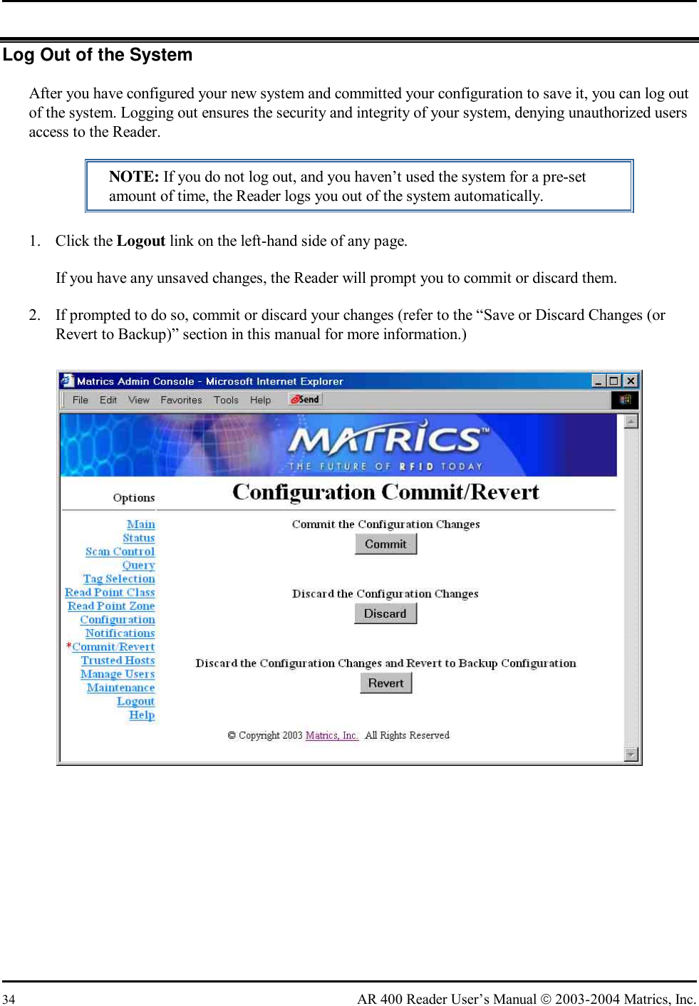
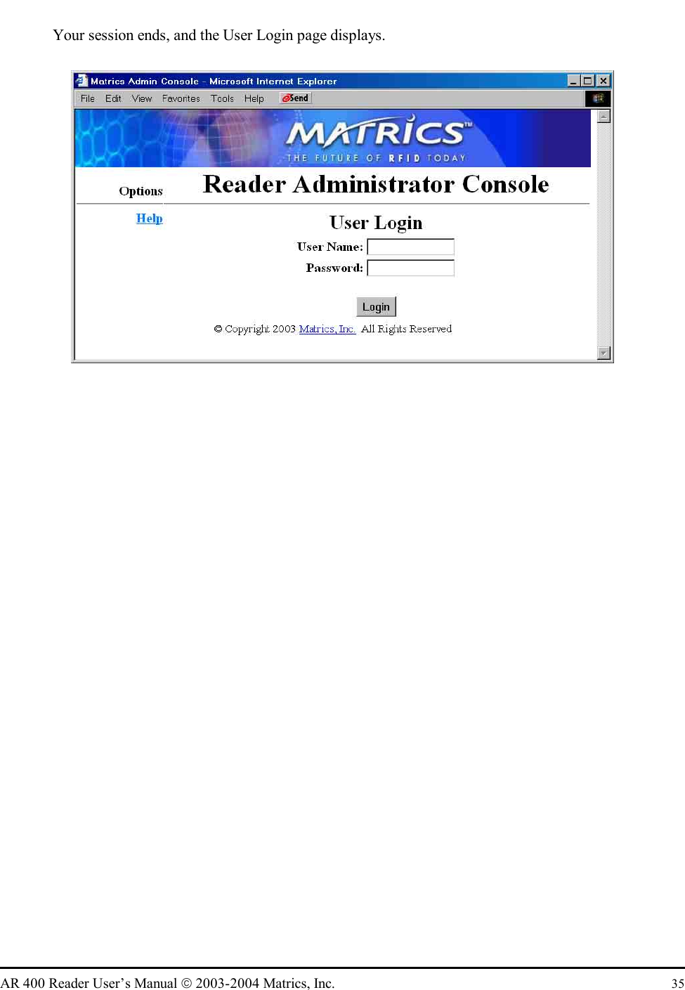
![AR 400 Reader User’s Manual 2003-2004 Matrics, Inc. 63 Log Out of the System When you are done using the Maintenance Console, you can log out of the system. Logging out ensures the security and integrity of your system, denying unauthorized users access to the Reader. NOTE: If you do not log out, and you haven’t used the system for a pre-set amount of time, the Reader logs you out of the system automatically. 1. Click the Logout link on the left-hand side of any page. If you have any unsaved changes, the Reader will prompt you to commit or discard them. 2. If prompted to do so, commit or discard your changes [refer to the “Save or Discard Changes (or Revert to Backup)” section provided previously in Section 3 of this User’s Manual for more information.] Your session ends, and the User Login page displays.](https://usermanual.wiki/Symbol-Technologies/AR400US.Revised-Manual/User-Guide-467204-Page-67.png)