Symbol Technologies AR4126 RFID SYSTEM User Manual AR400 UserManual
Symbol Technologies Inc RFID SYSTEM AR400 UserManual
UserManual.wiki
>
Symbol Technologies
>
AR4126 User Manual
USERS MANUAL
Navigation menu
Upload a User Manual
Namespaces
Wiki Guide
HTML
PDF
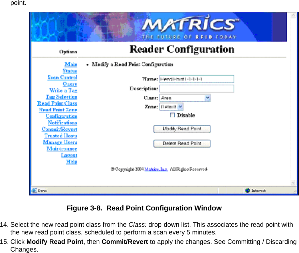
Info
Views
User Manual
Discussion / Help
Navigation


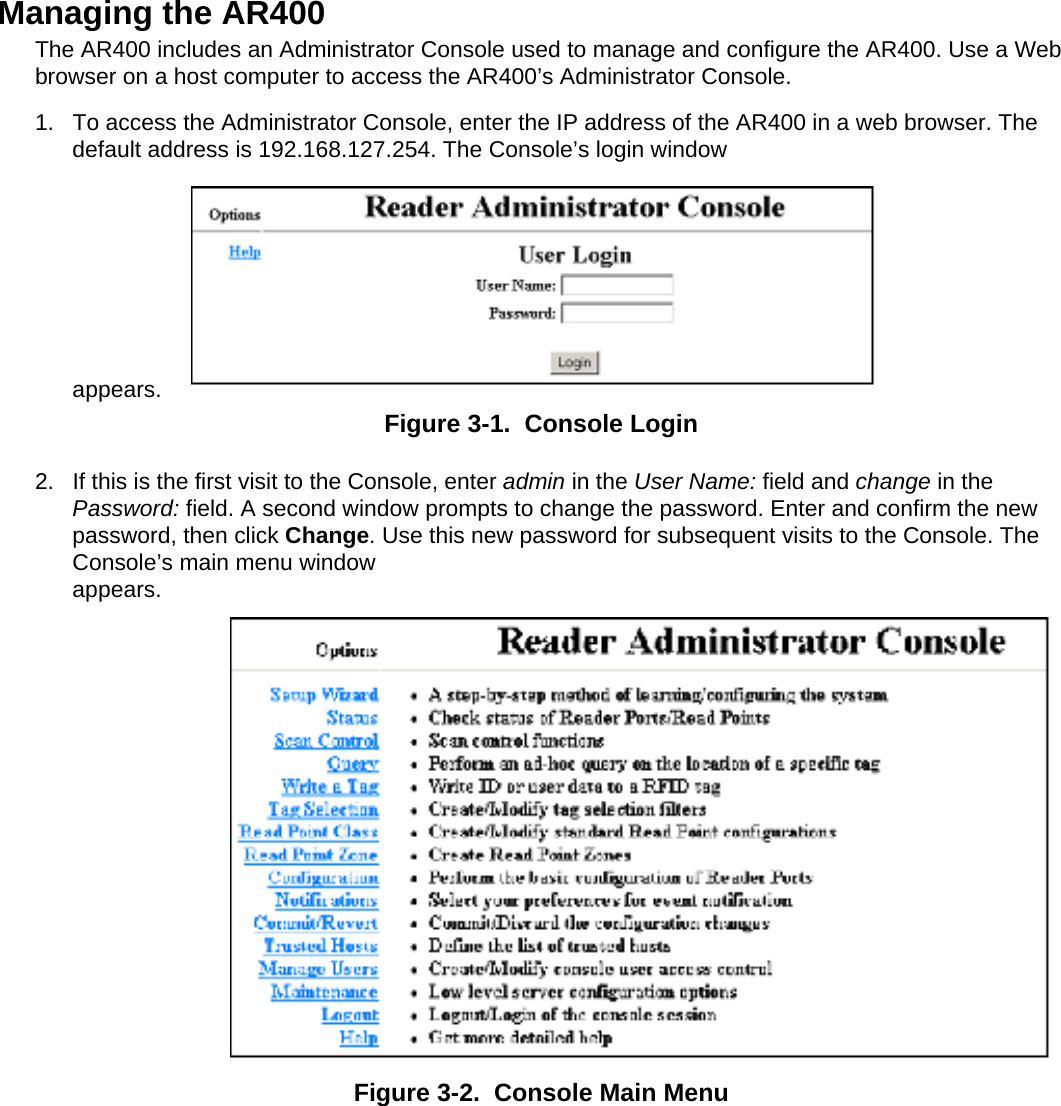
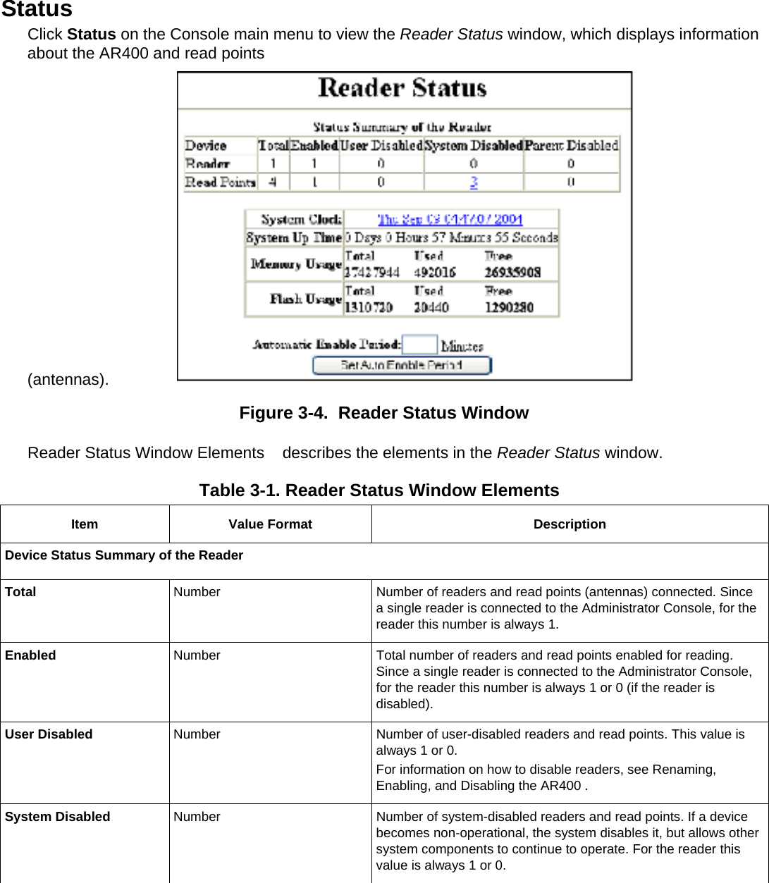
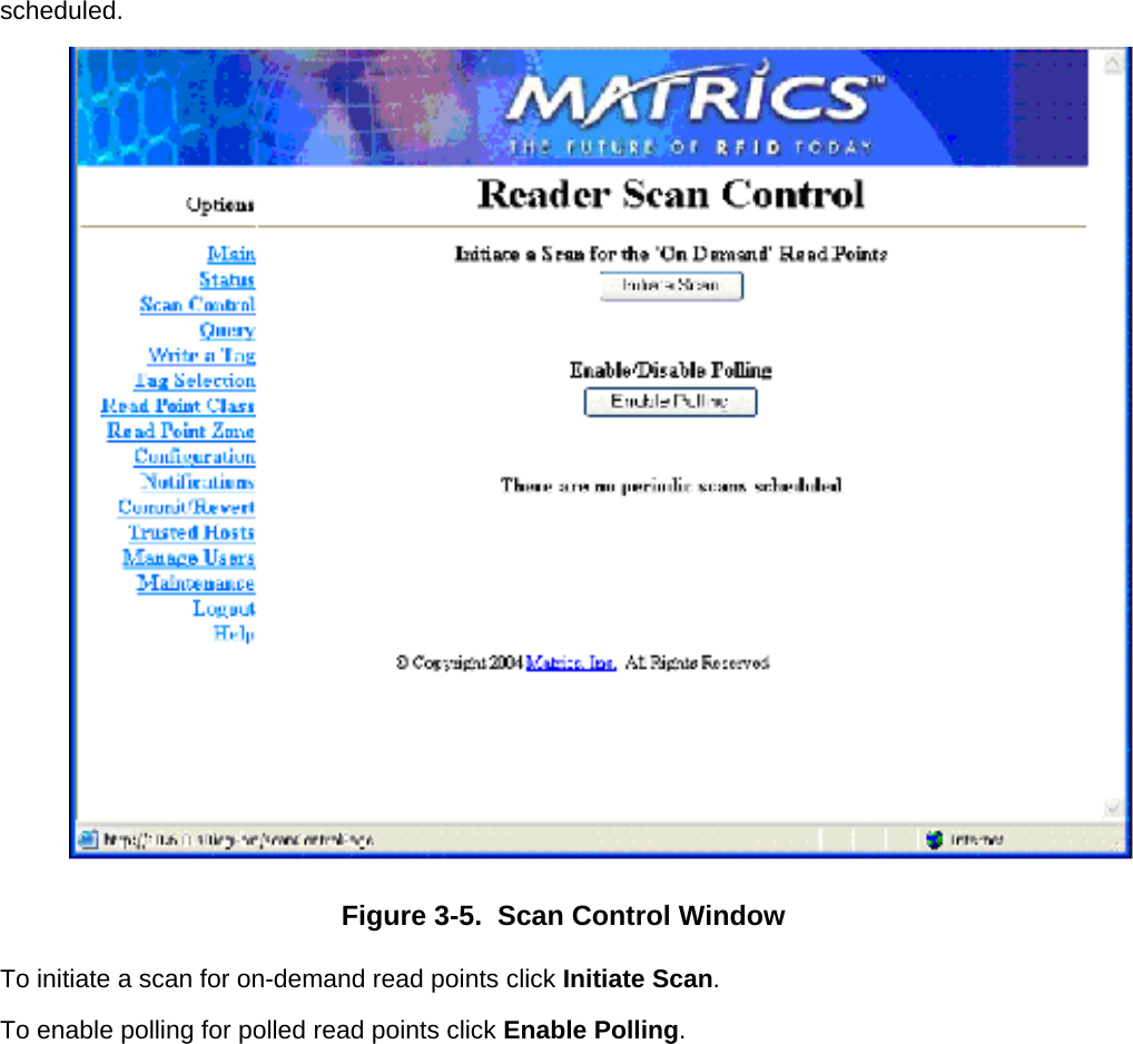
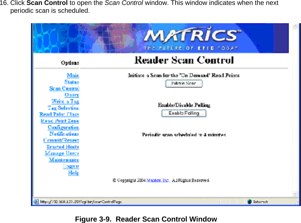
![Parent Disabled Number Devices dependent on a non-operational parent device are marked Parent Disabled. For example, when a reader is system-disabled, its read points are marked parent disabled. Reader Information System Clock [Weekday] [Month] [Day of the Month] [Hour:Minute:Second] [Year] Time of the reader system clock. Click on this to change the time of the reader system clock. System Up Time [Number of Days] [Number of Hours] [Number of Minutes] [Number of Seconds] The length of time that the reader has been running. Memory Usage Number of bytes Total amount of device memory, and amount of memory in use and available. Flash Usage Number of bytes Total amount of flash memory, and amount of memory in use and available. Automatic Enable Period Minutes After the specified number of minutes the system attempts to enable any degraded device that was system-disabled. Scan Control Click Scan Control on the Console main menu to view the Scan Control window, which allows initiating an on-demand scan and enabling / disabling polled read points. For periodic read points, the window displays when the next scan is](https://usermanual.wiki/Symbol-Technologies/AR4126/User-Guide-545395-Page-27.png)
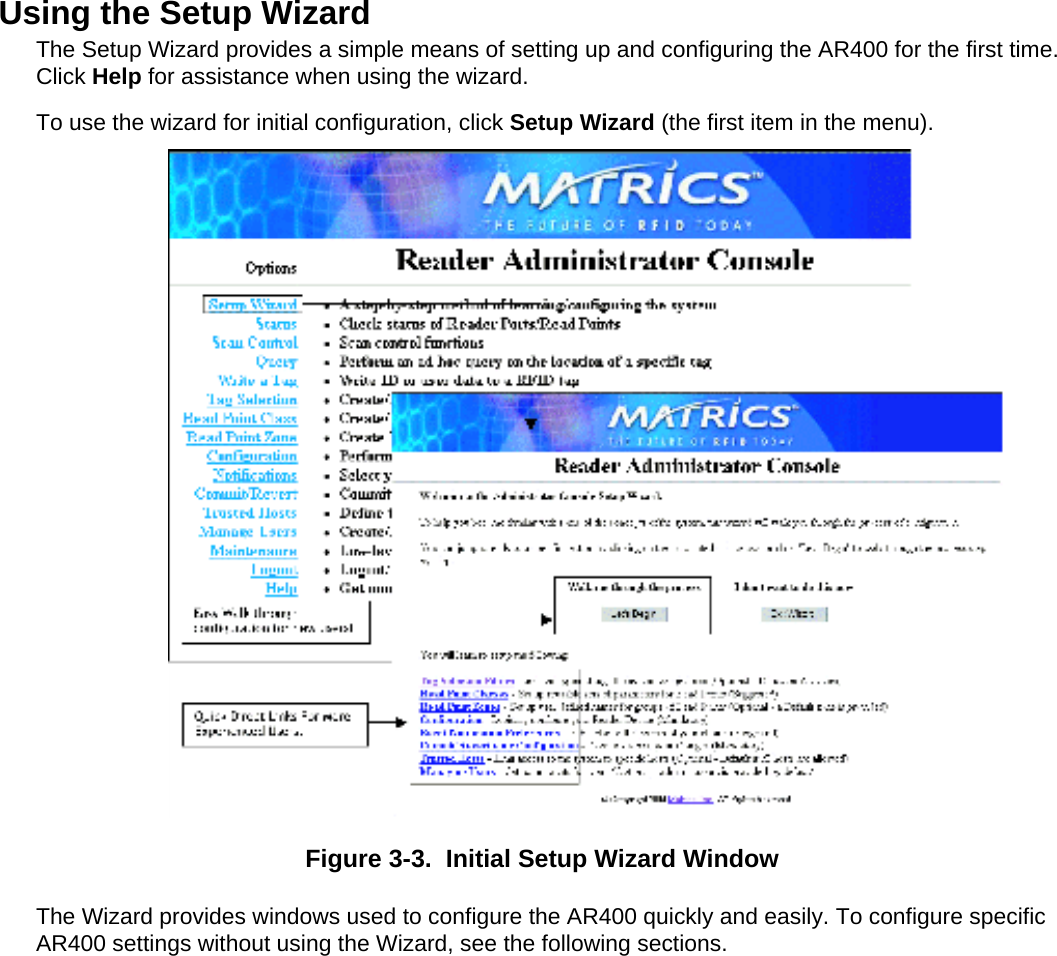
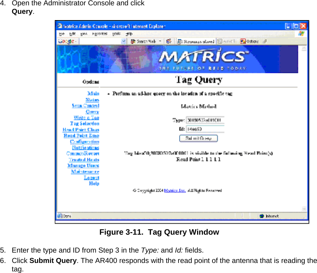
![Query Use the query feature to read tags and get their status information. The AR400 replies with one of the following tag status indications: • The tag is not known to the system. (The tag was never seen or imported.) • The tag is not visible to the system. (The tag is known to the system, but is currently not visible to any read point.) • The tag is visible at one or more read points. (A list of read points where the tag can be seen displays.) The tag ID and the type of the tag is required to query a tag. To obtain the tag ID and type of all tags the AR400 is reading: 1. Enable polling at the AR400 and configure read point classes as polled classes. 2. Open a new browser window and enter the following URL: http://[Reader IP Address] /cgi-bin/dataProxy?oper=queryTags XML containing the tag ID and type of all tags being read appears.Figure 3-10. Query Tags XML Window 3. Note the tag ID and type of the tag to query.](https://usermanual.wiki/Symbol-Technologies/AR4126/User-Guide-545395-Page-33.png)


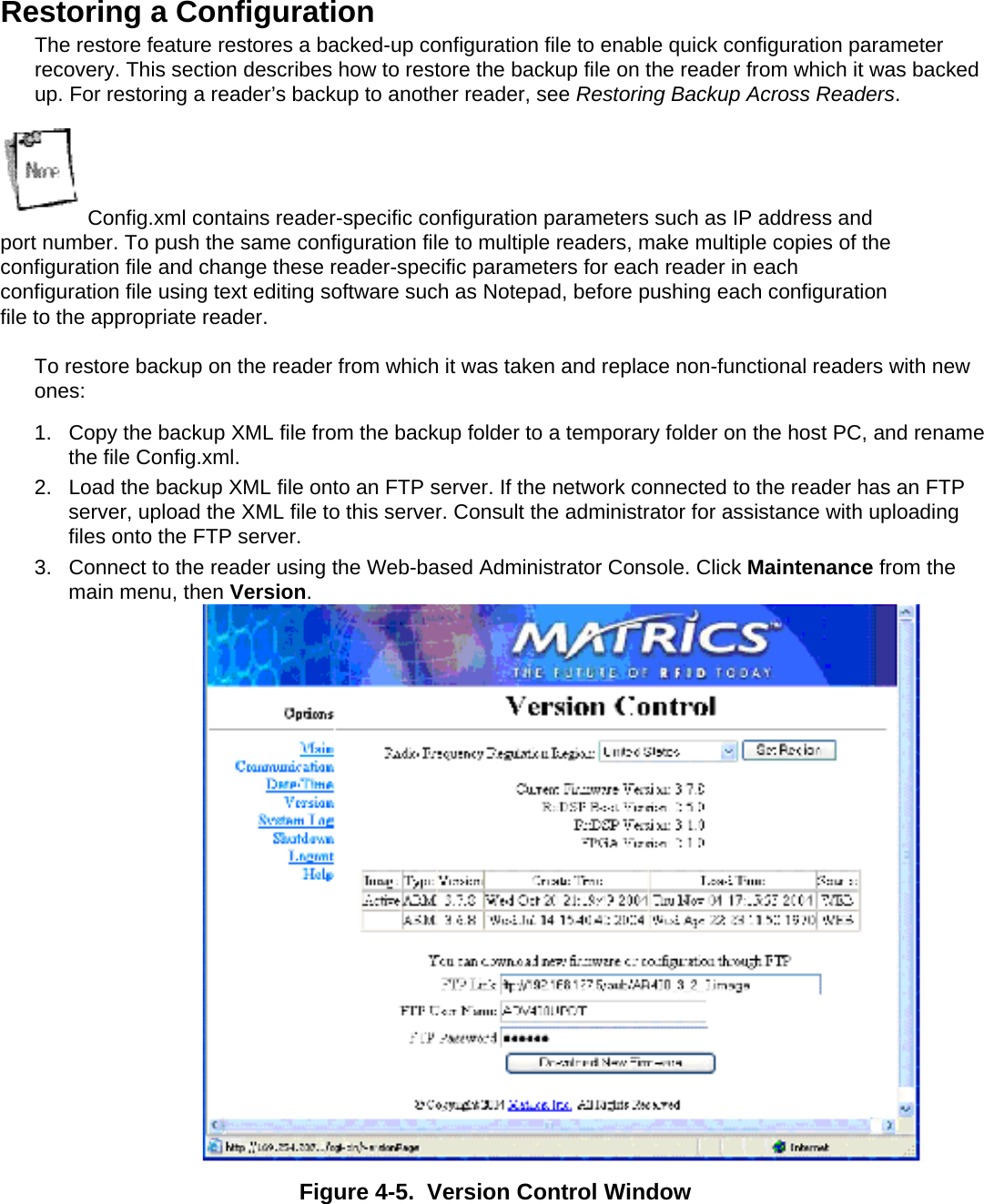
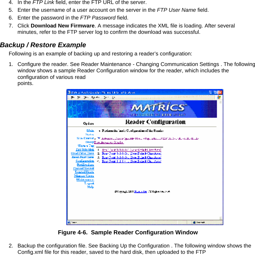
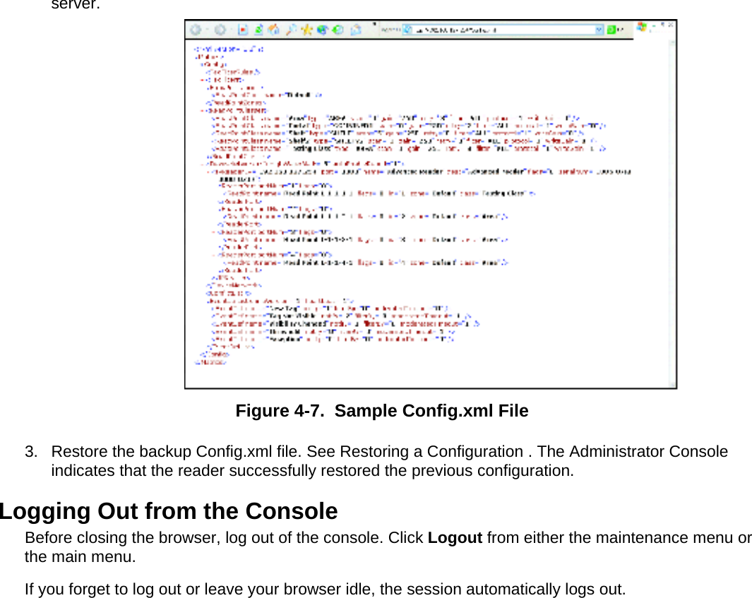
![Backing Up the Configuration The reader supports the following backup configuration functions: • Rolling back maintenance errors and restoring the reader to a particular date and time. • Pushing reader-specific changes made to the config.xml file to multiple readers, simplifying multi-reader management. • General configuration backup that can be restored when required, such as hardware replacement. To back up the reader's configuration: 1. Open the browser and enter the URL http://[Reader IP address]/Config.xml. For example, if the reader’s IP address is 123.123.123.123, enter: http://123.123.123.123/Config.xml An XML file similar to the following appears, depicting the current reader configuration.Figure 4-4. Sample Reader Configuration XML File 2. Save the XML file with a naming / date convention that facilitates recognizing the reader and the date of the backup. Most browsers allow saving XML files to the hard disk. In Internet Explorer, select File - Save As… 3. Click Save and use Windows Explorer to verify that the file is saved correctly.](https://usermanual.wiki/Symbol-Technologies/AR4126/User-Guide-545395-Page-63.png)