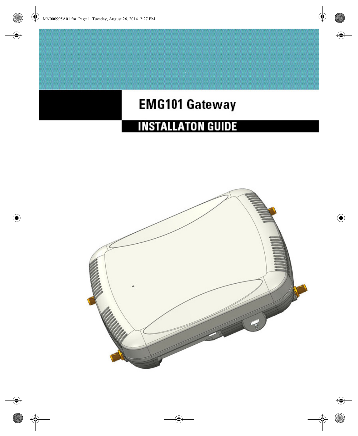
Symbol Technologies EMG101 802.15.4 Gateway User Manual EMG101 installation Guide

Symbol Technologies Inc 802.15.4 Gateway EMG101 installation Guide

User Manual.pdf

EMG101 GatewayINSTALLATION GUIDEMN000995A01.fm  Page 1  Tuesday, August 26, 2014  2:27 PM
2EMG101 GatewaySymbol® is a registered trademark, and The Enterprise Mobility Company is a trademark of Symbol Technologies, Inc. All other trademarks and service marks are proprietary to their respective owners. © 2014 Symbol Technologies, Inc. All Rights Reserved.MN000995A01.fm  Page 2  Tuesday, August 26, 2014  2:27 PM
Installation Guide 31.0 Introduction   . . . . . . . . . . . . . . . . . . . . . . . . . . . . . . . . . . . . . . . . . . . . . . . . . . . . . . 51.1 Document Conventions  . . . . . . . . . . . . . . . . . . . . . . . . . . . . . . . . . . . . . . . . . . . . 51.2 Warnings  . . . . . . . . . . . . . . . . . . . . . . . . . . . . . . . . . . . . . . . . . . . . . . . . . . . . . . .  51.3 Site Preparation  . . . . . . . . . . . . . . . . . . . . . . . . . . . . . . . . . . . . . . . . . . . . . . . . . . 61.4 Package Contents . . . . . . . . . . . . . . . . . . . . . . . . . . . . . . . . . . . . . . . . . . . . . . . . . 61.5 Features  . . . . . . . . . . . . . . . . . . . . . . . . . . . . . . . . . . . . . . . . . . . . . . . . . . . . . . . . 62.0 Hardware Installation . . . . . . . . . . . . . . . . . . . . . . . . . . . . . . . . . . . . . . . . . . . . . . 72.1 Installation Instructions  . . . . . . . . . . . . . . . . . . . . . . . . . . . . . . . . . . . . . . . . . . . .  72.2 Precautions . . . . . . . . . . . . . . . . . . . . . . . . . . . . . . . . . . . . . . . . . . . . . . . . . . . . . .  72.3 EMG101 Gateway Placement. . . . . . . . . . . . . . . . . . . . . . . . . . . . . . . . . . . . . . . .  82.3 Power Injector System . . . . . . . . . . . . . . . . . . . . . . . . . . . . . . . . . . . . . . . . . . . . .  82.5 Wall Mount Installation . . . . . . . . . . . . . . . . . . . . . . . . . . . . . . . . . . . . . . . . . . .  102.6 Suspended Ceiling T-Bar Installation . . . . . . . . . . . . . . . . . . . . . . . . . . . . . . . . .  112.7 LED Indicator. . . . . . . . . . . . . . . . . . . . . . . . . . . . . . . . . . . . . . . . . . . . . . . . . . . .  133.0 Basic Gateway Configuration . . . . . . . . . . . . . . . . . . . . . . . . . . . . . . . . . . . . . .  144.0 Specifications. . . . . . . . . . . . . . . . . . . . . . . . . . . . . . . . . . . . . . . . . . . . . . . . . . . .  154.1 Electrical Characteristics  . . . . . . . . . . . . . . . . . . . . . . . . . . . . . . . . . . . . . . . . . .  154.2 Physical Characteristics . . . . . . . . . . . . . . . . . . . . . . . . . . . . . . . . . . . . . . . . . . .  154.3 Radio Characteristics . . . . . . . . . . . . . . . . . . . . . . . . . . . . . . . . . . . . . . . . . . . . .  155.0 Regulatory Information . . . . . . . . . . . . . . . . . . . . . . . . . . . . . . . . . . . . . . . . . . . .  165.1 Regulatory Overview. . . . . . . . . . . . . . . . . . . . . . . . . . . . . . . . . . . . . . . . . . . . . .  165.2 Wireless Device Country Approvals . . . . . . . . . . . . . . . . . . . . . . . . . . . . . . . . . .  165.2.1 Frequency of Operation - FCC and IC . . . . . . . . . . . . . . . . . . . . . . . . . . . . .  165.3 Health and Safety Recommendations . . . . . . . . . . . . . . . . . . . . . . . . . . . . . . . .  175.3.1 Warnings for the use of Wireless Devices  . . . . . . . . . . . . . . . . . . . . . . . .  175.4 RF Exposure Guidelines  . . . . . . . . . . . . . . . . . . . . . . . . . . . . . . . . . . . . . . . . . . .  175.4.1 Safety Information . . . . . . . . . . . . . . . . . . . . . . . . . . . . . . . . . . . . . . . . . . .  175.5 International . . . . . . . . . . . . . . . . . . . . . . . . . . . . . . . . . . . . . . . . . . . . . . . . . . . .  175.6 Europe . . . . . . . . . . . . . . . . . . . . . . . . . . . . . . . . . . . . . . . . . . . . . . . . . . . . . . . . .  18MN000995A01.fm  Page 3  Tuesday, August 26, 2014  2:27 PM
4EMG101 Gateway5.7 US and Canada . . . . . . . . . . . . . . . . . . . . . . . . . . . . . . . . . . . . . . . . . . . . . . . . . .  185.8 Power Supply  . . . . . . . . . . . . . . . . . . . . . . . . . . . . . . . . . . . . . . . . . . . . . . . . . . .  185.9 Radio Frequency Interference Requirements - FCC . . . . . . . . . . . . . . . . . . . . . .  185.10 Radio Frequency Interference Requirements - Canada . . . . . . . . . . . . . . . . . .  195.10.1 Radio Transmitters . . . . . . . . . . . . . . . . . . . . . . . . . . . . . . . . . . . . . . . . . .  195.11 CE Marking and European Economic Area (EEA) . . . . . . . . . . . . . . . . . . . . . . .  205.12 Statement of Compliance . . . . . . . . . . . . . . . . . . . . . . . . . . . . . . . . . . . . . . . . .  205.14 Waste Electrical and Electronic Equipment (WEEE). . . . . . . . . . . . . . . . . . . . .  215.15 Turkish WEEE Statement of Compliance . . . . . . . . . . . . . . . . . . . . . . . . . . . . .  226.0 Support Information . . . . . . . . . . . . . . . . . . . . . . . . . . . . . . . . . . . . . . . . . . . . . . .  23MN000995A01.fm  Page 4  Tuesday, August 26, 2014  2:27 PM
Installation Guide 51 IntroductionEMG101 Gateways are components of Symbol Technologies Wireless Controller System. An EMG101 Gateway links to wireless 802.15.4 electronic shelf label tags. It installs in minutes anywhere a CAT-5e (or better) cable is located.The EMG101 Gateway ships with two single-band 2.4GHz 802.15.4 radios. The radios are configured for redundant operation. If the currently operating radio fails, the gateway will automatically activate the second radio.The EMG101 Gateway is approved under MODEL: EMG101.Symbol recommends the EMG101 Gateway receive power and transfer data through the same CAT-5e (or better) Ethernet cable using a Symbol Power Injector. The Power Injector ((Part No. AP-PSBIAS-2P2-AFR) is an 802.3af PoE injector. For information, see Power Injector System.A separate power supply (Part No. PWRS-147376-01R) is also available if you do not wish to use a Power Injector. This standard power supply just supplies power to the EMG101 Gateway’s power connector and does not converge power and Ethernet within a single cable connection.1.1    Document ConventionsThe following graphical alerts are used in this document to indicate notable situations:1.2    Warnings• Read all installation instructions and site survey reports, and verify correct equipment installation before connecting the EMG101 Gateway.• Remove jewelry and watches before installing this equipment. • Verify any device connected to this unit is properly wired and grounded.• Verify there is adequate ventilation around the device, and that ambient temperatures meet equipment operation specifications.NOTE Tips, hints, or special requirements that you should take note of.CAUTION Care is required. Disregarding a caution can result in data loss or equipment malfunction.WARNING! Indicates a condition or procedure that could result in personal injury or equipment damage.!MN000995A01.fm  Page 5  Tuesday, August 26, 2014  2:27 PM
6EMG101 Gateway1.3    Site PreparationTo prepare your deployment site for gateway installation:• Consult your site survey and network analysis reports to determine specific equipment placement, power drops, and so on.• Assign installation responsibility to the appropriate personnel.• Identify and document where all installed components are located• Ensure adequate, dust-free ventilation to all installed equipment• Prepare Ethernet port connections• Verify cabling is within the maximum 100 meter allowable length1.4    Package ContentsThe EMG101 Gateway ships with the following:• ESL101 Gateway• Installation Guide (This Guide)• Rubber Wall Mount Spacers (4)• Wall mount screw and anchor kit1.5    Features• One RJ-45 console connector• LED indicator• Safety wire tie point• Wall mount slots• Clips for suspended T-Bar mounting• DC power connectorAn EMG101 Gateway has one RJ-45 connector supporting an 10/100/1000 Ethernet port connection and requires 802.3af compliant power from an external source.The EMG101 Gateway contains runtime firmware which enables the unit to boot after either a power up or a watchdog reset. The runtime firmware on the gateway can be updated via the Ethernet interface.MN000995A01.fm  Page 6  Tuesday, August 26, 2014  2:27 PM
Installation Guide 72 Hardware Installation2.1    Installation InstructionsThe EMG101 Gateway can attach to a wall or mount under a suspended T-Bar. Select a mounting option based on the physical environment of the coverage area. Do not mount the EMG101 Gateway in a location not approved in a site survey.To prepare for the installation:1. Verify the contents of the box includes the intended EMG101 Gateway and accessory hardware.2. Review site survey and network analysis reports to determine the location and mounting position for the EMG101 Gateway.3. Connect a CAT-5 or better Ethernet cable to a PoE compatible device and run the cable to the installation site. Ensure there is sufficient cable slack to perform the installation steps.4. Determine whether the EMG101 Gateway is powered using a Power Injector system, combining data and power to the Gateway’s GE1/PoE port or will be powered from a conventional power adapter providing power only to the Gateway’s DC-48V connector.2.2    PrecautionsBefore installing the EMG101 Gateway:• Verify the intended deployment location is not prone to moisture or dust.• Verify the environment has a continuous temperature range between 0° C to 50° C.MN000995A01.fm  Page 7  Tuesday, August 26, 2014  2:27 PM
8EMG101 Gateway2.3    EMG101 Gateway PlacementFor optimal performance, install the EMG101 Gateway away from transformers, heavy-duty motors, fluorescent lights, microwave ovens, refrigerators and other industrial equipment. Signal loss can occur when metal, concrete, walls or floors block transmission. Install the EMG101 Gateway in an open area or add additional gateways as needed to improve coverage.Antenna coverage is analogous to lighting. Users might find an area lit from far away to be not bright enough. An area lit sharply might minimize coverage and create dark areas. Uniform antenna placement in an area (like even placement of a light bulb) provides even, efficient coverage.Place the EMG101 Gateway using the following guidelines:• Install the EMG101 Gateway at an ideal height of 10 feet from the ground.• Orient the EMG101 Gateway antennas (Part Number ML-2452-APA2-01) vertically for best reception.• Point the EMG101 Gateway antennas downward if attaching to the ceiling.To maximize the EMG101 Gateway’s radio coverage area, Symbol recommends conducting a site survey to define and document radio interference obstacles before installing the EMG101 Gateway.2.4    Power Injector SystemThe EMG101 Gateway can receive power via an Ethernet cable connected to the GE1/PoE port.When users purchase an Electronic Shelf Label (ESL) solution, they often need to place EMG101 Gateways in obscure locations. Power can be supplied from a dedicated connection or from a PoE injector. The Power Injector merges power and Ethernet into one cable, reducing the burden of installation and allowing optimal EMG101 Gateway placement in respect to the intended coverage area.The Power Injector (Part No. AP-PSBIAS-2P2-AFR) is an 802.3af PoE injector. The EMG101 Gateway can only use a Power Injector when connecting to the EMG101 Gateway’s GE1/PoE port. The Power Injector is separately ordered and not shipped with the EMG101 Gateway. A separate Power Injector is required for each EMG101 Gateway comprising the network.MN000995A01.fm  Page 8  Tuesday, August 26, 2014  2:27 PM
Installation Guide 9The Power Injector has no On/Off power switch. The Injector receives power and is ready for device connection and operation as soon as AC power is applied. Refer to the Installation Guide shipped with the Power Injector for a description of the device’s LED. The Power Injector can be installed free standing, on an even horizontal surface or wall mounted using the Power Injector’s wall mounting key holes.The following guidelines should be adhered to before cabling the Power Injector to an Ethernet source and an EMG101 Gateway:• Do not block or cover airflow to the Power Injector.• Keep the Power Injector away from excessive heat, humidity, vibration and dust.• The Power Injector isn’t a repeater, and does not amplify the Ethernet signal. For optimal performance, ensure the Power Injector is placed as close as possible to the Ethernet switch. This allows the EMG101 Gateway to be deployed away from power drops.• Ensure the cable length from the Ethernet source (host) to the Power Injector and EMG101 Gateway does not exceed 100 meters (333 ft).CAUTION To avoid problematic performance and restarts, disable PoE from a wired controller port connected to an EMG101 Gateway if mid-span power sourcing equipment (PSE) is used between the two, regardless of the manufacturer.CAUTION Ensure AC power is supplied to the Power Injector using an AC cable with an appropriate ground connection approved for the country of operation.!!MN000995A01.fm  Page 9  Tuesday, August 26, 2014  2:27 PM
10 EMG101 Gateway2.5    Wall Mount InstallationTo support wall mount installations, the EMG101 Gateway is fastened directly to a flat wall surface. The wall should be of gypsum board, plaster, wood or concrete in composition.To install the EMG101 Gateway to a wall surface:1. Orient the EMG101 Gateway by either its width or length.2. Mark the mounting surface at the target screw insertion points.3. At each point, drill a hole in the wall, insert an anchor, screw into the anchor the wall mounting screw and stop when there is 1mm between the screw head and the wall.4. If pre-drilling a hole, the recommended hole size is 2.8mm (0.11in.) if the screws are going directly into the wall and 6mm (0.23in.) if wall anchors are being used.5. If required, install and attach a security cable to the EMG101 Gateway lock port.6. Attach the antennas to their correct connectors.7. Place the large center opening of each of the mount slots over the screw heads.8. Slide the EMG101 Gateway down along the mounting surface to hang the mount slots on the screw heads.9. Cable the EMG101 Gateway using either the Power Injector solution or an approved line cord and power supply.For Symbol Power Injector installations:a. Connect an RJ-45 CAT5 Ethernet cable between the network data supply (host) and the Power Injector’s Data In connector.b. Connect an RJ-45 CAT5 Ethernet cable between the Power Injector’s Data & Power Out connector and the EMG101 Gateway.CAUTION EMG101 must only be connected to PoE networks without any connections to an outside plant power source.NOTE If not using the Power Injector to power the EMG101 Gateway, the only other approved power solution is the standard power supply (Part Number PWRS-147376-01R). The standard power supply does not converge data and power in one cable, and requires a separate data Ethernet connection in addition to a power connection. This product is intended to be supplied by a listed power adapter marked “Class 2” or “L.P.S” (or “Limited Power Source”) and rated from 48Vdc, 0.38A minimum.CAUTION An EMG101 Gateway should be wall mounted to concrete or plaster-wall-board (dry wall) only. Do not wall mount the EMG101 Gateway to combustible surfaces.!!MN000995A01.fm  Page 10  Tuesday, August 26, 2014  2:27 PM
Installation Guide 11c. Ensure the cable length from the Ethernet source (host) to the Power Injector and EMG101 Gateway does not exceed 100 meters (333 ft). The Power Injector has no On/Off power switch. The Power Injector receives power as soon as AC power is applied. For more information, see Power Injector System.For power adapter (Part Number PWRS-147376-01R) and line cord installations:a. Connect a RJ-45 CAT5e (or CAT6) Ethernet cable between the network data supply (host) and the EMG101 Gateway’s GE1/PoE.b. Verify the power adapter is correctly rated according the country of operation.c. Connect the power supply line cord to the power adapter.d. Attach the power adapter cable to the DC-48V power connector on the EMG101 Gateway.e. Attach the power supply line cord to a power supply.10. Verify the behavior of the EMG101 Gateway LED. For more information, see LED Indicator.11. The Gateway is ready to configure. For information on basic Gateway configuration, see Basic Gateway Configuration.2.6    Suspended Ceiling T-Bar InstallationA suspended ceiling mount requires holding the EMG101 Gateway up against the T-bar of a suspended ceiling grid and twisting the EMG101 Gateway chassis onto the T-bar.To install the EMG101 Gateway on a ceiling T-bar:1. If desired, install and attach a security cable to the EMG101 Gateway lock port.2. Attach the antennas to their correct connectors.3. Cable the EMG101 Gateway using either the Power Injector solution or an approved line cord and power supply.For Symbol Power Injector installations:a. Connect an RJ-45 CAT5 Ethernet cable between the network data supply (host) and the Power Injector’s Data In connector.b. Connect an RJ-45 CAT5 Ethernet cable between the Power Injector’s Data & Power Out connector and the Gateway.c. Ensure the cable length from the Ethernet source (host) to the Power Injector and Gateway does not exceed 100 meters (333 ft). The Power Injector has no On/Off power switch. The Power Injector receives power as soon as AC power is applied. For more information, see Power Injector System.CAUTION Do not connect to the power source until the cabling of the EMG101 Gateway is complete. Ensure PoE is not connected to the EMG101 Gateway’s console connector or risk rendering the console connector permanently inoperable.!MN000995A01.fm  Page 11  Tuesday, August 26, 2014  2:27 PM
12 EMG101 GatewayFor power adapter (Part Number PWRS-147376-01R) and line cord installations:a. Connect a RJ-45 CAT5e (or CAT6) Ethernet cable between the network data supply (host) and the Gateway’s GE1/PoE.b. Verify the power adapter is correctly rated according the country of operation.c. Connect the power supply line cord to the power adapter.d. Attach the power adapter cable to the DC-48V power connector on the Gateway.e. Attach the power supply line cord to a power supply.4. Verify the behavior of the Gateway LED. For more information, see Basic Gateway Configuration.5. Align the bottom of the ceiling T-bar with the back of the Gateway.6. Orient the Gateway chassis by its length and the length of the ceiling T-bar.7. Rotate the Gateway chassis 45 degrees clockwise.8. Push the back of the Gateway chassis on to the bottom of the ceiling T-bar.9. Rotate the Gateway chassis 45 degrees counter-clockwise. The clips click as they fasten to the T-bar.10. Verify the behavior of the Gateway LED. For more information, see LED Indicator.11. The Gateway is ready to configure. For information on basic Gateway device configuration, see Basic Gateway Configuration.MN000995A01.fm  Page 12  Tuesday, August 26, 2014  2:27 PM
Installation Guide 132.7    LED IndicatorThe EMG101 Gateway has a single LED on the front of the unit.When the EMG101 Gateway is not powered up, the LED will be amber. When the EMG101 Gateway is powered up and running, the LED will be green. MN000995A01.fm  Page 13  Tuesday, August 26, 2014  2:27 PM
14 EMG101 Gateway3 Basic Gateway ConfigurationTo provide the EMG101 Gateway with a basic configuration:1. Power up the Gateway.2. By default, the Gateway will obtain an IP address from the DHCP server.3. If no DHCP server is available, a Static IP address should be configured. You will need to contact Symbol technical support to obtain a valid password.4. To configure a Static IP address:a. Connect to the Gateway via the Console port.b. Login as motgw and switch to superuser (su) mode.c. Edit the interfaces file at /etc/network/interfaces to enter the IP address.5. You will also need to configure the Channel and PAN ID.To configure the Channel and PAN ID:a. Connect to the Gateway via the Console port (if the Gateway IP address needs to be configured), or via ssh (if the Gateway has already been configured).b. Login as motgw and switch to superuser (su) mode.c. Edit the coord.conf file.d. Update the COORD_PANID and COORD_CHANNEL values to be used for the Gateway deployment. Contact Symbol technical support to identify the required values for these parameters.e. Ensure that the SPI_INDEX value is set to zero or a positive value.f. Update the REGULATORY_REGION parameter to the appropriate value (example: EU1, NA1, NA2, and NA3). Contact Symbol support for the correct value for your deployment.g. Update the STORE_ID parameter with the store ID to be used for the deployment location.h. Save the updated coord.conf file.MN000995A01.fm  Page 14  Tuesday, August 26, 2014  2:27 PM
Installation Guide 154 Specifications4.1    Electrical CharacteristicsAn EMG101 Gateway has the following electrical characteristics:4.2    Physical CharacteristicsAn EMG101 Gateway has the following physical characteristics:4.3    Radio CharacteristicsAn EMG101 Gateway has the following radio characteristics: Max DC Power Consumption6W (125mA@48V) Dimensions 6.0 (Length) x 5.5 (Width) x 1.63 (Tall) - Inches152.4 (Length) x 139.7 (Width) x 41.1 (Tall) - MillimetersHousing PlasticWeight 0.60 lbs/0.272 kgOperating Temperature32°F to 122°F/0°C to 50°CStorage Temperature -40°F to 158°F/-40°C to 70°COperating Humidity 5 to 95% Relative Humidity non-condensingStorage Humidity 85% Relative Humidity non-condensingOperating Altitude(max)8,000 ft @ 28°CStorage Altitude(max)30,000 ft @ 12°CElectrostatic Discharge+/-8V Air and +/-4kV Contact @ 50% Relative HumidityOperating Channels Channels 11-25 (2405 to 2475 MHz)Max Transmit Power  10 dBmMN000995A01.fm  Page 15  Tuesday, August 26, 2014  2:27 PM
16 EMG101 Gateway5 Regulatory Information5.1    Regulatory OverviewThis device is approved under Symbol Technologies, Inc.This guide applies to Model Number EMG101.Symbol devices are designed to be compliant with rules and regulations in locations they are sold and will be labeled as required.Local language translations are available at the following website: https://portal.motorolasolutions.com/Support/US-EN/Wireless+NetworksAny changes or modifications to Symbol equipment, not expressly approved by Symbol, could void the user’s authority to operate the equipment.When Symbol devices are professionally installed, the Radio Frequency Output Power will not exceed the maximum allowable limit for the country of operation.Antennas: Use only the supplied or an approved replacement antenna. Unauthorized antennas, modifications, or attachments could cause damage and may violate regulations.Declared maximum operating temperature: 50°C.5.2    Wireless Device Country ApprovalsRegulatory markings, subject to certification, are applied to the device signifying the radio(s) is/are approved for use in the following countries: United States, Canada, and Europe.Please refer to the Declaration of Conformity (DoC) for details of other country markings. This is available at http://www.motorolasolutions.com/docNote: Europe includes, Austria, Belgium, Bulgaria, Czech Republic, Cyprus, Denmark, Estonia, Finland, France, Germany, Greece, Hungary, Iceland, Ireland, Italy, Latvia, Liechtenstein, Lithuania, Luxembourg, Malta, Netherlands, Norway, Poland, Portugal, Romania, Slovak Republic, Slovenia, Spain, Sweden, Switzerland and the United Kingdom.Operation of the device without regulatory approval is illegal.5.2.1    Frequency of Operation – FCC and IC 2.4 GHz OnlyThe available channels for 802.15.4 operation in the US are Channels 11 to 25. The range of channels is limited by firmware.MN000995A01.fm  Page 16  Tuesday, August 26, 2014  2:27 PM
Installation Guide 175.3    Health and Safety Recommendations5.3.1    Warnings for the use of Wireless DevicesPlease observe all warning notices with regard to the usage of wireless devices.PacemakersPacemaker manufacturers recommended that a minimum of 15cm (6 inches) be maintained between a handheld wireless device and a pacemaker to avoid potential interference with the pacemaker. These recommendations are consistent with independent research and recommendations by Wireless Technology Research.Persons with Pacemakers:• Should ALWAYS keep the device more than 15cm (6 inches) from their pacemaker when turned ON• Should not carry the device in a breast pocket• Should use the ear furthest from the pacemaker to minimize the potential for interference• If you have any reason to suspect that interference is taking place, turn OFF your device. Other Medical DevicesPlease consult your physician or the manufacturer of the medical device, to determine if the operation of your wireless product may interfere with the medical device.5.4    RF Exposure Guidelines5.4.1    Safety InformationReducing RF Exposure—Use ProperlyOnly operate the device in accordance with the instructions supplied.5.5    InternationalThe device complies with internationally recognized standards covering human exposure to electromagnetic fields from radio devices. For information on “International” human exposure to eletromagnic fields refer to the Symbol Declaration of Conformity (DoC) at http://www.motorolasolutions.com/doc.For further information on the safety of RF energy from wireless devices - see http://responsibility.motorolasolutions.com/index.php/downloads/Located under Wireless Communications and HealthMN000995A01.fm  Page 17  Tuesday, August 26, 2014  2:27 PM
18 EMG101 Gateway5.6    EuropeElectronic Shelf GatewayTo comply with EU RF exposure requirements, this device must be used according to installation instructions. Other operating configurations should be avoided.To satisfy EU RF exposure requirements, a transmitting device must operate with a minimum separation distance of 20 cm or more from a person's body.5.7    US and CanadaCo-located statementTo comply with FCC RF exposure compliance requirements, the antenna used for this transmitter must not be co-located or operating in conjunction with any other transmitter/antenna except those already approved in this filling.To comply with FCC/IC RF exposure requirements, antennas that are mounted externally or operating near users must operate with a minimum separation distance of 20 cm from all persons.To satisfy US and Canadian RF exposure requirements, a transmitting device must operate with a minimum separation distance of 20cm or more from a person's body.Pour satisfaire aux exigences Américaines et Canadiennes d'exposition aux radiofréquences, un dispositif de transmission doit fonctionner avec une distance de séparation minimale de 20cm ou plus de corps d'une personne.5.8    Power SupplyUse ONLY a Symbol/Motorola approved UL LISTED ITE (IEC/EN 60950-1, LPS) power supply with electrical ratings: Output 48Vdc, min 0.38A, with a maximum ambient temperature of at least 50° C. Use of alternative power supply will invalidate any approvals given to this unit and may be dangerous.This device must be powered from a 802.3af or 802.3at compliant power source which has been certified by the appropriate agencies, or by a Motorola approved UL LISTED ITE (IEC/EN 60950-1, LPS) power supply with electrical ratings: Output 48Vdc, min 0.35A, with a recommended temperature greater than 50 degrees C. Use of an alternative power supply will invalidate any approvals given to this unit and ma be dangerous.5.9    Radio Frequency Interference Requirements—FCCThis equipment has been tested and found to comply with the limits for a Class B digital device, pursuant to Part 15 of the FCC rules. These limits are designed to provide reasonable protection against harmful interference in a residential installation. This equipment generates, uses and can radiate radio frequency energy and, if not installed and used in accordance with the instructions, may cause harmful interference to radio communications. However there is no guarantee that interference will not occur in a particular installation. If this equipment does cause harmful interference to radio or television reception, which can MN000995A01.fm  Page 18  Tuesday, August 26, 2014  2:27 PM
Installation Guide 19be determined by turning the equipment off and on, the user is encouraged to try to correct the interference by one or more of the following measures:• Reorient or relocate the receiving antenna• Increase the separation between the equipment and receiver• Connect the equipment into an outlet on a circuit different from that to which the receiver is connected• Consult the dealer or an experienced radio/TV technician for helpRadio Transmitters (Part 15)This device complies with Part 15 of the FCC Rules. Operation is subject to the following two conditions: (1) this device may not cause harmful interference, and (2) this device must accept any interference received, including interference that may cause undesired operation.5.10    Radio Frequency Interference Requirements – CanadaIn accordance with the regulations of Industry Canada, this radio transmitter can operate with an antenna of a type and a maximum gain (or lower) approved for the transmitter by Industry Canada. With the aim of reducing the risk of radio interference to other users, the chosen antenna type and it gain should be selected so that the equivalent isotropically radiated power (e.i.r.p.) does not exceed the intensity necessary for the establishment of a satisfactory connection.Conformément à la réglementation d'Industrie Canada, le présent émetteur radio peut fonctionner avec une antenne d'un type et d'un gain maximal (ou inférieur) approuvé pour l'émetteur par Industrie Canada. Dans le but de réduire les risques de brouillage radioélectriqueà l'intention des autres utilisateurs, il faut choisir le type d'antenne et son gain de sorte que la puissance isotrope rayonnée équivalente (p.i.r.e.) ne dépasse pas l'intensité nécessaire àl'établissement d'une communication satisfaisante.This radio transmitter EMG101 has been approved by Industry Canada to operate with the antenna types listed below and having a maximum gain allowable and the impedance required for each type of antenna. The antenna types not included in this list, or whose gain is higher than the maximum gain indicates, are strictly prohibited for the operation of the transmitter.Dipole  3.2 dBi 50 ohmsCet émetteur EMG101 radio a été approuvé par Industrie Canada pour fonctionner avec les types d'antenne énumérés ci-dessous et ayant un gain maximal admissible et l'impédance requise pour chaque type d'antenne. Les types d'antennes ne figurent pas dans cette liste, ou dont le gain est supérieur au gain maximal indique, sont strictement interdits pour le fonctionnement de l'émetteur.5.10.1    Radio TransmittersCAN ICES-3 (B)/NMB-3(B) This device complies with Industry Canada license-exempt RSS standard(s). Operation is subject to the following two conditions: (1) this device may not cause interference, and (2) this device must accept any interference, including interference that may cause undesired operation of the device.MN000995A01.fm  Page 19  Tuesday, August 26, 2014  2:27 PM
20 EMG101 GatewayCet appareil est conforme avec Industrie Canada RSS exemptes de licence. Son fonctionnement est soumis aux deux conditions suivantes: (1) cet appareil ne peut pas provoquer d'interférences, et (2) cet appareil doit accepter toute interférence, y compris les interférences qui peuvent causer un mauvais fonctionnement de l'appareil.Label Marking: The Term "IC:" before the radio certification only signifies that Industry Canada technical specifications were met.5.11    CE Marking and European Economic Area (EEA)The use of 2.4 GHz RLAN’s, for use through the EEA, have the following restrictions:• Maximum radiated transmit power of 100 mW EIRP in the frequency range 2.400 -2.4835 GHz.5.12    Statement of ComplianceSymbol hereby declares that this device is in compliance with the essential requirements and other relevant provisions of Directive 1999/5/EC. A Declaration of Conformity (DoC) may be obtained from http://www.motorolasolutions.com/doc.MN000995A01.fm  Page 20  Tuesday, August 26, 2014  2:27 PM
Installation Guide 215.13    Waste Electrical and Electronic Equipment (WEEE)English: For EU Customers: All products at the end of their life must be returned to Symbol for recycling. For information on how to return product, please go to: http://www.motorolasolutions.com/recycling/weee.Français: Clients de l'Union Européenne: Tous les produits en fin de cycle de vie doivent être retournés à Symbol pour recyclage. Pour de plus amples informations sur le retour de produits, consultez : http://www.motorolasolutions.com/recycling/weee.Español: Para clientes en la Unión Europea: todos los productos deberán entregarse a Symbol al final de su ciclo de vida para que sean reciclados. Si desea más información sobre cómo devolver un producto, visite: http://www.motorolasolutions.com/recycling/weee.Български: За клиенти от ЕС: След края на полезния им живот всички продукти трябва да се връщат на Symbol за рециклиране. За информация относно връщането на продукти, моля отидете на адрес: http://www.motorolasolutions.com/recycling/weee.Deutsch: Für Kunden innerhalb der EU: Alle Produkte müssen am Ende ihrer Lebensdauer zum Recycling an Symbol zurückgesandt werden. Informationen zur Rücksendung von Produkten finden Sie unter http://www.motorolasolutions.com/recycling/weee.Italiano: per i clienti dell'UE: tutti i prodotti che sono giunti al termine del rispettivo ciclo di vita devono essere restituiti a Symbol al fine di consentirne il riciclaggio. Per informazioni sulle modalità di restituzione, visitare il seguente sito Web: http://www.motorolasolutions.com/recycling/weee.Português: Para clientes da UE: todos os produtos no fim de vida devem ser devolvidos à Symbol para reciclagem. Para obter informações sobre como devolver o produto, visite: http://www.motorolasolutions.com/recycling/weee.Nederlands: Voor klanten in de EU: alle producten dienen aan het einde van hun levensduur naar Symbol te worden teruggezonden voor recycling. Raadpleeg http://www.motorolasolutions.com/recycling/weee voor meer informatie over het terugzenden van producten.Polski: Klienci z obszaru Unii Europejskiej: Produkty wycofane z eksploatacji naleźy zwrócić do firmy Symbol w celu ich utylizacji. Informacje na temat zwrotu produktów znajdują się na stronie internetowej http://www.motorolasolutions.com/recycling/weee./recycling/weee.Čeština: Pro zákazníky z EU: Všechny produkty je nutné po skonèení jejich životnosti vrátit spoleènosti Symbol k recyklaci. Informace o zpùsobu vrácení produktu najdete na webové stránce: http://www.motorolasolutions.com/recycling/weee.Eesti: EL klientidele: kõik tooted tuleb nende eluea lõppedes tagastada taaskasutamise eesmärgil Symbol 'ile. Lisainformatsiooni saamiseks toote tagastamise kohta külastage palun aadressi: http://www.motorolasolutions.com/recycling/weee.Magyar: Az EU-ban vásárlóknak: Minden tönkrement terméket a Symbol vállalathoz kell eljuttatni újrahasznosítás céljából. A termék visszajuttatásának módjával kapcsolatos tudnivalókért látogasson el a http://www.motorolasolutions.com/recycling/weee weboldalra.Svenska: För kunder inom EU: Alla produkter som uppnått sin livslängd måste returneras till Symbol för återvinning. Information om hur du returnerar produkten finns på http://www.motorolasolutions.com/recycling/weee.Suomi: Asiakkaat Euroopan unionin alueella: Kaikki tuotteet on palautettava kierrätettäväksi Symbol Technologies-yhtiöön, kun tuotetta ei enää käytetä. Lisätietoja tuotteen palauttamisesta on osoitteessa http://www.motorolasolutions.com/recycling/weee.MN000995A01.fm  Page 21  Tuesday, August 26, 2014  2:27 PM
22 EMG101 GatewayDansk: Til kunder i EU: Alle produkter skal returneres til Symbol til recirkulering, når de er udtjent. Læs oplysningerne om returnering af produkter på: http://www.motorolasolutions.com/recycling/weee.Ελληνικά: Για πελάτες στην Ε.Ε.: Όλα τα προϊόντα, στο τέλος της διάρκειας ζωής τους, πρέπει να επιστρέφονται στην Symbol για ανακύκλωση. Για περισσότερες πληροφορίες σχετικά με την επιστροφή ενός προϊόντος, επισκεφθείτε τη διεύθυνση http://www.motorolasolutions.com/recycling/weee στο ∆ιαδίκτυο.Malti: Għal klijenti fl-UE: il-prodotti kollha li jkunu waslu fl-aħħar tal-ħajja ta' l-użu tagħhom, iridu jiġu rritornati għand Symbol għar-riċiklaġġ. Għal aktar tagħrif dwar kif għandek tirritorna l-prodott, jekk jogħġbok żur: http://www.motorolasolutions.com/recycling/weee.Românesc: Pentru clienţii din UE: Toate produsele, la sfârşitul duratei lor de funcţionare, trebuie returnate la Symbol pentru reciclare. Pentru informaţii despre returnarea produsului, accesaţi: http://www.motorolasolutions.com/recycling/weee.Slovenski: Za kupce v EU: vsi izdelki se morajo po poteku življenjske dobe vrniti podjetju Symbol za reciklažo. Za informacije o vračilu izdelka obiščite: http://www.motorolasolutions.com/recycling/weee.Slovenčina: Pre zákazníkov z krajín EU: Všetky výrobky musia byť po uplynutí doby ich životnosti vrátené spoločnosti Symbol na recykláciu. Bližšie informácie o vrátení výrobkov nájdete na: http://www.motorolasolutions.com/recycling/weee.Lietuvių: ES vartotojams: visi gaminiai, pasibaigus jų eksploatacijos laikui, turi būti grąžinti utilizuoti į kompaniją „Symbol“. Daugiau informacijos, kaip grąžinti gaminį, rasite: http://www.motorolasolutions.com/recycling/weee.Latviešu: ES klientiem: visi produkti pēc to kalpošanas mūža beigām ir jānogādā atpakaļ Symbol otrreizējai pārstrādei. Lai iegūtu informāciju par produktu nogādāšanu Symbol, lūdzu, skatiet: http://www.motorolasolutions.com/recycling/weee.Türkçe: AB Müşterileri için: Kullanım süresi dolan tüm ürünler geri dönüştürme için Symbol 'ya iade edilmelidir. Ürünlerin nasıl iade edileceği hakkında bilgi için lütfen şu adresi ziyaret edin: http://www.motorolasolutions.com/recycling/weee.5.14    TURKISH WEEE Statement of ComplianceEEE Yönetmeliğine UygundurMN000995A01.fm  Page 22  Tuesday, August 26, 2014  2:27 PM
Installation Guide 236 Support InformationIf you have a problem with your equipment, contact support for your region.Contact information is available at: https://portal.motorolasolutions.com/Support/US-ENWhen contacting Symbol technical support, please provide the following information:• Serial number of the unit• Model number or product name• Software type and version numberSymbol responds to calls by e-mail, telephone, or fax within the time limits set forth in support agreements. If you purchased your product from a Symbol business partner, contact that business partner for support.6.1    Customer Support Web SitesThe Symbol Support Web site, located at: https://portal.motorolasolutions.com/Support/US-EN.provides information and online assistance including developer tools, software downloads, product manuals and online repair requests.6.2    ManualsSymbol documentation is available at:https://portal.motorolasolutions.com/Support/US-EN/Wireless+Networks.6.3    General InformationObtain additional information by contacting Symbol at:Telephone (North America): 1-800-722-6234Telephone (International): +1-631-738-5200Website: http://www.motorolasolutions.comMN000995A01.fm  Page 23  Tuesday, August 26, 2014  2:27 PM
24 EMG101 GatewayMN000995A01.fm  Page 24  Tuesday, August 26, 2014  2:27 PM
Installation Guide 25MN000995A01.fm  Page 25  Tuesday, August 26, 2014  2:27 PM
26 EMG101 GatewayMN000995A01.fm  Page 26  Tuesday, August 26, 2014  2:27 PM
Installation Guide 27MN000995A01.fm  Page 27  Tuesday, August 26, 2014  2:27 PM
Symbol Technologies, IncOne Symbol PlazaHoltsville, New York 11742-1300http://www.symbol.comSymbol® is a registered trademark, and The Enterprise Mobility Company is a trademark of Symbol Technologies, Inc. All other trademarks and service marks are proprietary to their respective owners. © 2014 Symbol Technologies, Inc. All Rights Reserved.MN000995A01 Revision A August 2014MN000995A01.fm  Page 28  Tuesday, August 26, 2014  2:27 PM

Navigation menu