Symbol Technologies LA3021-100 LA3021-100 WLAN PC Card User Manual
Symbol Technologies Inc LA3021-100 WLAN PC Card Users Manual
Contents
Users Manual

Spectrum24
Wireless LAN Adapter
Models 3020 PC Card &
3025 ISA Adapter
Product Reference Guide
70-20505-01
October 1998

ii Spectrum24 Wireless LAN Adapter User Guide
Copyright
Copyright © 1998 by Symbol Technologies, Inc. All rights reserved.
No part of this publication may be modified or adapted in any way, for any purposes without permission in writing from Symbol.
The material in this manual is subject to change without notice.
Symbol reserves the right to make changes to any product to improve reliability, function, or design.
No license is granted, either expressly or by implication, estoppel, or otherwise under any Symbol Technologies, Inc.,
intellectual property rights. An implied license only exists for equipment, circuits, and subsystems contained in Symbol products.
Symbol, the Symbol logo and Spectrum24 are registered trademarks of Symbol Technologies, Inc.
Other product names mentioned in this manual may be trademarks or registered trademarks of their respective companies and
are hereby acknowledged.
Novell and LAN Workplace are registered trademarks of Novell Inc.
Patents
This product is covered by one or more of the following U.S. and foreign Patents:
U.S. Patent No.4,360,798; 4,369,361; 4,387,297; 4,460,120; 4,496,831; 4,593,186; 4,603,262; 4,607,156;
4,652,750; 4,673,805; 4,736,095; 4,758,717; 4,816,660; 4,845,350; 4,896,026; 4,897,532; 4,923,281; 4,933,538;
4,992,717; 5,015,833; 5,017,765; 5,021,641; 5,029,183; 5,047,617; 5,103,461; 5,113,445; 5,130,520 5,140,144;
5,142,550; 5,149,950; 5,157,687; 5,168,148; 5,168,149; 5,180,904; 5,229,591; 5,230,088; 5,235,167; 5,243,655;
5,247,162; 5,250,791; 5,250,792; 5,262,627; 5,262,628; 5,266,787; 5,278,398; 5,280,162; 5,280,163; 5,280,164;
5,280,498; 5,304,786; 5,304,788; 5,306,900; 5,321,246; 5,324,924; 5,337,361; 5,367,151; 5,373,148; 5,378,882;
5,396,053; 5,396,055; 5,399,846; 5,408,081; 5,410,139; 5,410,140; 5,412,198; 5,418,812; 5,420,411; 5,436,440;
5,444,231; 5,449,891; 5,449,893; 5,468,949; 5,471,042; 5,478,998; 5,479,000; 5,479,002; 5,479,441; 5,504,322;
5,519,577; 5,528,621; 5,532,469; 5,543,610; 5,545,889; 5,552,592; 5,578,810; 5,581,070; 5,589,679; 5,589,680;
5,608,202; 5,612,531; 5,619,028; 5,664,229; 5,668,803; 5,675,139; 5,693,929; 5,698,835; 5,705,800; 5,714,746;
5,723,851; 5,734,152; 5,734,153; 5,745,794; 5,754,587; 5,658,383; D305,885; D341,584; D344,501; D359,483;
D362,453; D362,435; D363,700; D363,918; D370,478; D383,124; D391,250.
Invention No. 55,358; 62,539; 69,060; 69,187 (Taiwan); No. 1,601,796; 1,907,875; 1,955,269 (Japan).
European Patent 367,299; 414,281; 367,300; 367,298; UK 2,072,832; France 81/03938; Italy 1,138,713.
Symbol Technologies, Inc.
One Symbol Plaza
Holtsville, N.Y. 11742-1300
Telephone:(800)SCAN234/(516)738-2

Spectrum24 Wireless LAN Adapter User Guide iii
Regulatory Addendum
Congratulations on your purchase of this Symbol Technologies product. It is manufactured to the highest standards to
ensure trouble-free operation and durability. In order to comply with various U.S. and International regulatory requirements, we
have included this addendum with your product. It is an all-encompassing document that applies to the complete line of
Symbol products. Therefore, many of the labels shown, and statements indigenous to other devices may not apply to your
particular product.
Radio Frequency Interference Requirements
This device has been tested and found to comply with the limits for a Class A digital device pursuant to Part 15 of the Federal
Communications Commissions Rules and Regulation. These limits are designed to provide reasonable protection against
harmful interference when the equipment is operated in a commercial environment. This equipment generates, uses, and can
radiate radio frequency energy and, if not installed and used in accordance with the instruction manual, may cause harmful
interference to radio communications. Operation of this equipment in a residential area is likely to cause harmful interference
in which case the user will be required to correct the interference at his own expense.
However, there is no guarantee that interference will not occur in a particular installation. If the equipment does cause harmful
interference to radio or television reception, which can be determined by turning the equipment off and on, the user is
encouraged to try to correct the interference by one or more of the
following measures:
•Re-orient or relocate the receiving antenna.
•Increase the separation between the equipment and receiver.
•Connect the equipment into an outlet on a circuit different from that which the receiver is connected.
•Consult the dealer or an experienced radio/TV technician for help.
Radio Frequency Interference Requirements -
Canada
This Class A digital apparatus meets the requirements of the Canadian Interference-Causing Equipment Regulations.
CE Marking and European Union Compliance
Products intended for sale within the European Union are marked with the CEMark which indicates compliance
to applicable Directives and European Normes (EN), as follows. Amendments to these Directives or ENs are
included: Normes (EN), as follows.
Applicable Directives:
•Electromagnetic Compatibility Directive 89/336/EEC
•Low Voltage Directive 73/23/EEC
Applicable Standards:
•EN 55 022 - Limits and Methods of Measurement of Radio Interference Characteristics of Information
technology Equipment
•EN 50 082-1 - Electromagnetic Compatibility - Generic Immunity Standard, Part 1: Residential, commercial,
Light Industry

iv Spectrum24 Wireless LAN Adapter User Guide
•IEC 801.2 - Electromagnetic Compatibility for Industrial Process Measurement and Control Equipment Part 2:
Electrostatic Discharge Requirements
•IEC 801.3 - Electromagnetic Compatibility for Industrial Process Measurement and Control Equipment Part 3:
Radiated Electromagnetic Field Requirements
•IEC 801.4 - Electromagnetic Compatibility for Industrial Process Measurement and Control Equipment Part 4: Electrical
Fast Transients Requirements
•EN 60 950 + Amd 1 + Amd 2 - Safety of Information Technology Equipment Including Electrical Business Equipment
•EN 60 825-1 (EN 60 825) - Safety of Devices Containing Lasers
RF Devices
Symbol’s RF products are designed to be compliant with the rules and regulations in the locations into which they are sold and
will be labeled as required. The majority of Symbol’s RF devices are type approved and do not require the user to obtain license
or authorization before using the equipment. Any changes or modifications to Symbol Technologies equipment not expressly
approved by Symbol Technologies could void the user’s authority to operate the equipment.
Telephone Devices (Modems) - United States
If this product contains an internal modem it is compliant with Part 68 of the Federal Communications Commission Rules and
Regulations and there will be a label on the product showing the FCC ID Number and the REN, Ringer Equivalence Number.
The REN is used to determine the quantity of devices which maybe connected to the telephone line. Excessive RENs on the
telephone line may result in the device not ringing in response to an incoming call. In most but not all areas, the sum of the
RENs should not exceed 5.0. To be certain of the number of devices that may be connected to the line, as determined by the
total number of RENs, contact the telephone company to determine the maximum REN for the calling area.
If the modem causes harm to the telephone network, the telephone company will notify you in advance; however, if advance
notice is not practical, you will be notified as soon as possible. Also, you will be advised of your right to file a complaint with the
FCC if you believe it is necessary.
The telephone company may make changes in its facilities, equipment, operations or procedures that could affect the operation
of the modem. If this happens the telephone company will provide advance notice so you may make any necessary
modifications to maintain uninterrupted service.
Telephone Devices (Modems) - Canada
If this product contains an internal modem it is compliant with CS-03 of Industry Canada and there will be a Canadian
certification number (CANADA: ____) on a label on the outside of the product. This certification means that the equipment
meets certain telecommunications network protective, operational and safety requirements. The Department does not
guarantee the equipment will operate to the user’s satisfaction.
Before installing this equipment, users should ensure that it is permissible to be connected to the facilities of the local
telecommunications company. The equipment must also be installed using an acceptable method of connection. In some
cases, the company’s inside wiring associated with a single-line, individual service maybe extended by means of a certified
convector assembly (telephone extension cord). The customer should be aware that compliance with the above conditions may
not prevent degradation of service in some situations.
Repairs to certified equipment should be made by an authorized Canadian maintenance facility designated by the supplier. Any
repairs or alterations made by the user to this equipment, or equipment malfunctions, may give the telecommunications
company cause to request the user to disconnect the equipment.
User should ensure for their own protection that the electrical ground connections of the power utility, telephone lines and
internal metallic water pipe system, if present, are connected together. This precaution may be particularly important in
rural areas.
CAUTION: User should not attempt to make such connections themselves, but should contact the appropriate electric inspection
authority, or electrician, as appropriate.
The Load Number (LN) assigned to each terminal device denotes the percentage of the total load to be connected to the
telephone loop which is used by the device, to prevent overloading. The termination of a loop may consist of any combination
of devices, subject only to the requirement that the total of the Load Numbers of all devices not exceed 100.

Spectrum24 Wireless LAN Adapter User Guide v
The Load Number is located on a label on the product.
Contact your local Symbol Technologies, Inc., representative for service and support;
Symbol Technologies, Inc.,
Canadian Sales and Service
2540 Matheson Boulevard East
Mississauga, Ontario
Canada L4W 4Z2
Phone - 905 629 7226
Laser Devices
Symbol products using lasers comply with US 21CFR1040.10, Subchapter J and IEC825/EN 60 825 (or IEC825-1/EN 60
825-1, depending on the date of manufacture). The laser classification is marked one of the labels on the product.
Class 1 Laser devices are not considered to be hazardous when used for their intended purpose. The following statement is
required to comply with US and international regulations:
CAUTION: Use of controls, adjustments or performance of procedures other than those specified herein may result in hazardous
visible or invisible laser light exposure.
Class 2 laser scanners use a low power, visible light diode. As with any very bright light source, such as the sun, the user should
avoid staring directly into the light beam. Momentary exposure to a Class 2 laser is not known to be harmful.
Laser information labels are found in the product Quick Reference Guide.

vi Spectrum24 Wireless LAN Adapter User Guide

Spectrum24 Wireless LAN Adapter User Guide vii
About This Document
Reference Documents
This Reference Guide refers to the following documents:
RFC’s (Request For Comments) may be found on the Web at: http://www.ctrl-
c.lin.se/ftp/DOC/RFC.
Conventions
Terminal text is depicted as shown on a 4140 terminal screen.
Keystrokes are indicated as follows:
Typeface conventions used include.
Part Number Document Title
70-20135-02 Single High Performance Antenna (ML-2499-HPA1-00/
Twin High Performance Diversity Antenna (ML-2499-DVA
1-00)
70-20136-01 Mountable F-Plane Antenna (ML-2499-DSA1-00)
70-20137-02 Universal Acess Point Wall Bracket (ML-2499-APB1-00)
ENTER identifies a key.
FUNC, CTRL, C identifies a key sequence. Press and release each key
in turn.
Press A+B means to press the indicated keys simultaneously.
Hold A+B means to hold down the indicated keys. Used in
combination with another keystroke.
<angles> indicates mandatory parameters in a given syntax.
[brackets] for command line, indicates available parameters; in
configuration files brackets act as separators for options.
Italics indicates the first time a term is used, a book title,
information to be replaced by an actual value, and
menu titles.

viii Spectrum24 Wireless LAN Adapter User Guide
This manual uses the following for certain conditions or types of information:
Indicates tips or special requirements.
Indicates conditions that can cause equipment damage or
data loss.
Indicates a condition or procedure that is potentially
dangerous. Only qualified, Symbol-trained personnel
should attempt to correct or perform.
Special Definitions:
Screen is the device on a terminal where the terminal shows data.
A display is an arrangement of data on a screen.
‘single quotes’ indicates the exact setting for a parameter.
Screen indicates monitor screen dialog. Also indicates user input.
Terminal indicates text shown on a radio terminal screen.

Spectrum24 Wireless LAN Adapter User Guide ix
Customer Support
Symbol Technologies is committed to providing its customers with World
Class Customer Service and Technical Support. The Symbol Support Center
is the single point of contact for any technical problem, question or
support issue.
The Support Center is operational 365 days a year, 24 hours a day, staffed
by full-time professional Technical Specialists.
If Symbol Technical Specialists cannot solve the problem immediately within
its tiered technical support center, access to all technical disciplines within
Symbol become available for further assistance and support. First
response/contact within 24 hours or one business day. Response by email,
fax or telephone.
North American Contacts
Inside North America, contact Symbol by:
Symbol Technologies, Inc.
One Symbol Plaza
Holtsville, New York 11742-1300
Telephone: 1-516-738-2400/1-800-SCAN 234
Fax: 1-516-738-5990
•Symbol Support Center:
– telephone: 1-800-653-5350
– fax: (516) 563-5410
– Email: support@symbol.com
– International Contacts

x Spectrum24 Wireless LAN Adapter User Guide
Outside North America, contact Symbol by:
Symbol Technologies Technical Support
12 Oaklands Park
Berkshire, RG41 2FD, United Kingdom
Tel: 011-44-118-945-7000 or 1-516-738-2400 ext. 6213
Additional Information
Obtain additional information by contacting Symbol at:
•1-800-722-6234, inside North America
•+1-516-738-5200, in/outside North America
•http://www.symbol.com/

Contents
Spectrum24 Wireless LAN Adapter Product Reference Guide xi
Chapter 1 Introduction............................................... 1
Chapter 2 Wireless LAN Adapter ............................... 3
2.1 MU Mode Operation ........................................4
2.2 MicroAP Mode Operation .................................5
2.3 1 and 2 Mbps Operation ..................................6
2.4 Mobile IP (roaming across routers) Description ..8
2.5 Power Management .........................................8
2.6 Card and Socket Services..................................9
2.7 Plug and Play ...................................................9
2.8 Spectrum24 Adapter LED Descriptions ..............9
Chapter 3 System Software Supported ..................... 11
Chapter 4 Hardware Installation.............................. 13
4.1 Preparation ....................................................13
4.2 Installing the PC Card.....................................13
4.3 End-Cap Antenna Installation .........................16
4.4 End-Cap Antenna Removal.............................16
4.5 Installing the WLAN ISA Adapter.....................18
4.5.1 External Antenna Connection ...............19
Chapter 5 Firmware Update..................................... 21
5.1 Verifying The Firmware Version.......................21
Chapter 6 Windows 95/NT Driver Installations ........ 23
6.1 Windows 95 Driver Introduction.....................23
6.2 New Features For v4.00 .................................24
6.3 Current Features in Windows 95.....................24
6.4 Windows 95 Driver/Transport Updates............24
6.5 Windows 95 Driver And Transport Uninstall
(Version 4.00 Or Earlier).......................................25
6.6 Windows 95 Driver Installation .......................26

xii Spectrum24 Wireless LAN Adapter Product Reference Guide
6.6.1 Preparation ..........................................26
6.7 Windows 95 Retail Version .............................26
6.8 Windows 95 OSR2 Version .............................27
6.9 Windows 95 Setup .........................................29
6.10 Configuration...............................................30
6.11 Windows NT 4.0/3.51 Driver Introduction.....31
6.12 New Features For v4.00 ...............................32
6.13 Current Features For NT...............................32
6.14 Current Limitations For NT............................33
6.15 Workstation/Server Primary Installation.........33
6.15.1 Preparation........................................33
6.16 Windows NT 4.0...........................................34
6.17 Windows NT 3.51.........................................36
6.18 First Time Network Installation......................38
6.19 Windows NT 4.0...........................................38
6.20 Windows NT 3.51.........................................40
6.21 Existing Network Installation.........................43
6.22 Windows NT 4.00.........................................44
6.22.1 Windows NT 3.51...............................46
6.23 Windows NT Driver Update ..........................49
6.24 Windows NT 4.0...........................................49
6.25 Windows NT 3.51.........................................50
6.25.1 Network Adapter Configuration..........50
6.26 Windows NT 4.00.........................................50
6.27 Windows NT 3.51.........................................51
Chapter 7 DOS/Windows For Workgroups Driver
Installation............................................53
7.1 Preventing Memory Range Conflicts ................53
7.2 Spectrum24 Automated Driver Installation ......54
7.3 NDIS Manual Installation................................55
7.4 Modifying Config.sys ......................................56

Spectrum24 Wireless LAN Adapter Product Reference Guide xiii
7.5 Modifying Autoexec.bat ..................................56
7.6 Modifying Protocol.ini.....................................57
7.7 ODI Manual Installation .................................57
7.8 Modifying Autoexec.bat ..................................58
7.9 Modifying Net.cfg...........................................58
7.10 Keyword usage.............................................59
7.11 Enabling Plug and Play .................................59
7.12 Enabling CardServices ..................................60
7.13 Windows for Workgroups (v3.11) ..................62
7.14 Installing The Driver .....................................62
Appendix A Windows 95 Network Configuration
Properties ............................................A 1
Appendix B Windows NT Network Configuration
Parameters .......................................... B 1
Appendix C Windows NT/95
Utilities Setup ......................................C 1
C.1 Windows NT 4.0 and Windows 95
S24INFO .....................................................C 1
C.1.1 Preparation......................................... C 1
C.1.2 Installing S24INFO.............................. C 1
C.1.3 Starting S24INFO................................ C 2
C.1.4 Uninstalling S24INFO ......................... C 2
C.2 Windows NT 3.51 S24INFO...................C 2
C.2.1 Preparation......................................... C 2
C.2.2 Installing S24INFO.............................. C 3
C.2.3 Starting S24INFO................................ C 3
C.2.4 Uninstalling S24INFO ......................... C 3
C.3 Windows NT 4.0 and Windows 95
S24UTIL.......................................................C 4
C.3.1 Preparation......................................... C 4

xiv Spectrum24 Wireless LAN Adapter Product Reference Guide
C.3.2 Installing S24UTIL ............................... C 4
C.3.3 Starting S24UTIL ................................. C 4
C.3.4 Uninstalling S24UTIL........................... C 5
C.4 Windows NT 3.51 S24UTIL ...................C 5
C.4.1 Preparation......................................... C 5
C.4.2 Installing S24UTIL ............................... C 6
C.4.3 Starting S24UTIL ................................. C 6
C.4.4 Uninstalling S24UTIL........................... C 6
C.5 Reinstalling S24UTIL or S24INFO...........C 6
C.5.1 Conversion ......................................... C 7
C.6 Windows Utilities Description.................C 7
C.7 Monitor Spectrum24 MU Mode..............C 8
C.8 Using S24INFO.....................................C 8
C.9 Statistics and Configuration Screen
Descriptions In MU Mode...........................C 10
C.10 Statistics and Configuration Screen
Descriptions In MAP Mode .........................C 20
C.11 S24INFO Troubleshooting Hints ........C 27
C.11.1 Symptom: Adapter
not communicating..................................... C 27
C.11.2 Symptom: Adapter associated
but not communicating............................... C 27
C.11.3 Symptom: Out of Memory Error....... C 28
C.12 Using S24UTIL ..................................C 28
C.13 Utility Frame .....................................C 30
Appendix D Spectrum24 DOS Keywords................. D 1
Appendix E Spectrum24 DOS Utilities......................E 1
E.1 S_WFA....................................................E 1

Spectrum24 Wireless LAN Adapter Product Reference Guide xv
E.2 S_UTIL ................................................... E 2
E.3 Examples ............................................... E 4
E.4 S_INFO.................................................. E 5
E.5 Configuration/Status.............................. E 7
E.5.1 Transmit Statistics ............................... E 10
E.5.2 AP Table (MU Mode only).................... E 11
E.5.3 Associated MU Table
(MicroAP Mode only).................................... E 11
E.5.4 Transmit And Receive Statistics Table... E 12
E.6 S_VER .................................................. E 12
E.7 S_UPDATE............................................ E 13
Appendix F WLAN Adapter Specifications ................F 1
Appendix G Roaming Across Routers/Mobile IP
Setup...................................................G 1
G.1 Roaming Across Routers And Mobile IP
Configuration ............................................. G 1
G.2 Configuring the Adapter For Mobile IP
in Windows 95............................................ G 1
G.3 Configuring the Adapter For Mobile IP
In Windows NT 4.0/3.51............................. G 2
G.4 Configuring the Adapter For Mobile IP
In DOS ....................................................... G 3
G.4.1 Preparation......................................... G 3
Appendix H Troubleshooting...................................H 1
H.1 Windows 95 Troubleshooting Tips..........H 1
H.2 Windows NT 4.0/3.51 Troubleshooting..H 2
H.2.1 Useful tools......................................... H 4

xvi Spectrum24 Wireless LAN Adapter Product Reference Guide
H.3 Windows NT ERRORS ............................H 5
Index.....................................................Index 1

Spectrum24 Wireless LAN Adapter Product Reference Guide 1
Chapter 1 Introduction
Spectrum24 is a frequency-hopping, spread spectrum
network that operates between 2.4 and 2.5 GHz.
Spectrum24 operates similarly to Ethernet networks without
a wired network infrastructure. Spread spectrum
communication provides a high-capacity network within
large or small environments. Interference reduction makes
it ideal for mobile communications and real-time data
access applications.
•Spectrum24 bridging architecture allows
communication between wired network devices and
mobile devices.
•Spectrum24 switchable data rates allow 1 Mbps
and 2 Mbps devices to communicate in the same
network environment.
•Spectrum24 supports the IEEE 802.11 specification.
This open architecture allows Spectrum 24
devices to communicate with wireless devices from
other manufacturers.
•Spectrum24 allows mobile devices to roam
throughout large facilities while remaining connected
to the LAN.
•Spectrum24 allows protocol firmware upgrades while
devices remain operational.
•Spectrum24 antenna diversity feature alternates
between antennas with the best reception, increasing
overall performance.

Introduction
2 Spectrum24 Wireless LAN Adapter Product Reference Guide

Spectrum24 Wireless LAN Adapter Product Reference Guide 3
Chapter 2 Wireless LAN Adapter
The Spectrum24 Wireless LAN (WLAN) adapter allows ISA
(Industry Standard Architecture) or PC Card equipped host
systems to configure, connect to and establish a
Spectrum24 network. The ISA adapter version of the
WLAN implements the Plug and Play standard. When
installed in a system with a Plug and Play BIOS (basic input
output system), the card requests system resources. The
system allocates an Interrupt Request (IRQ), Input-Output
(I/O) port and memory address range. Host systems
without Plug and Play BIOS acquire Plug and Play
functionality through the CSS (Card and Socket services)
utilities that normally come bundled with system software.
Features Include:
•Low power operation for battery-powered devices with
PC Card slots.
•Standard NDIS (Network Driver Interface
Specification) and ODI (Open Data-link
Interface) drivers.
•Windows 95, NT 4.0/3.51 driver support.
•Card and Socket Services support.
•Plug and Play support.
•Antenna options (molded external antenna available
for PC Card only).
•Power management (Continuously Aware Mode or
Power Save Polling mode)
Wireless LAN Adapter
4 Spectrum24 Wireless LAN Adapter Product Reference Guide
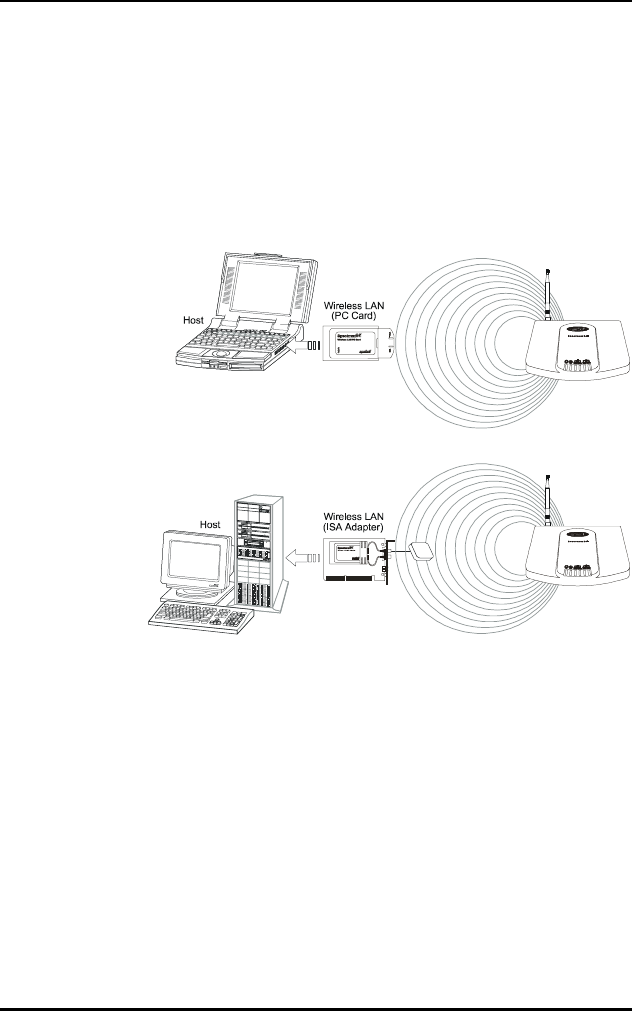
2.1 MU Mode Operation
In the Mobile Unit (MU) mode, the WLAN adapter
connects to an Access Point (AP) or another WLAN
installed system operating in MicroAP mode. The MU
mode allows the device to roam freely between AP
cells in the network. MUs appear as network nodes to
other devices.
Wireless LAN Adapter
Spectrum24 Wireless LAN Adapter Product Reference Guide 5
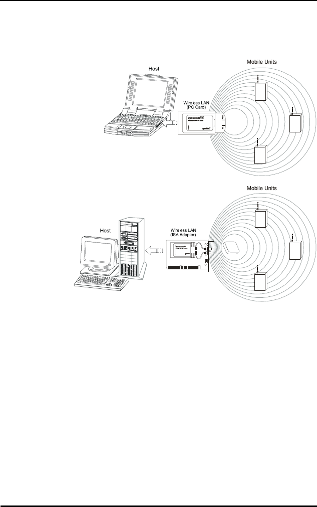
2.2 MicroAP Mode Operation
In the MicroAP mode, the WLAN adapter performs as an
Access Point. The Spectrum24 WLAN adapter installed in a
PC without another network connection, establishes a
single-cell wireless network coverage area for all 802.11
devices in MU mode. Each MicroAP needs to have a
unique ESS_ID. Cells can coexist as separate, individual
networks at the same site without interference. The
MicroAP does not roam, but it does support roaming. It
has to operate in continuous aware mode in order to
support CAM and PSP MUs. MUs can operate only within
the cell established by WLAN adapter in this mode. The
MicroAP mode supports up to 16 MUs. An Access Control
List (ACL) containing the MU MAC addresses within the

Wireless LAN Adapter
6 Spectrum24 Wireless LAN Adapter Product Reference Guide
established cell allows only the specified MUs (within the
ACL) to associate with a MicroAP. Set the MicroAP and the
MU to the appropriate data rates to communicate. Refer to
the MicroAP Rate Control Table for the rates. The table
below shows the compatible data rates. The adapter is
configured to operate in the MicroAP mode through the
Spectrum24 Network configuration dialog screen for
Windows 95 and the Spectrum24 NT Installation dialog in
Windows NT (refer to the Windows NT/95 installation
section). Configure the adapters to operate in the MicroAP
mode by setting several keywords (refer to Appendix C) in
the NDIS (protocol.ini) or ODI (net.cfg) configuration files.
Table 2-1: MicroAP Rate Control Table
2.3 1 and 2 Mbps Operation
The Spectrum24 Wireless LAN Adapter can support 1 or
2 Mbps data rates when properly configured. See table
below for configuration dependencies and refer to the
software configuration sections in this document for setup.
The adapter supports a dynamically switched 1 and 2
Mbps data rate (dynamic rate control) in a properly
configured network environment. The MU and the Access
Point need to be compatible (refer to the Spectrum24
Access Point User Guide for a detailed Access Point
Mobile Unit Micro AP (Rate Control)
Supported
Transmit
Rates
Base
Rate 1
Base
Rate 1,
Tx Rate 2
(Default)
Base
Rate 1,
Base
Rate 2
Base Rate
2
1 1 1 N/A N/A
1 & 2
(Default)
11 & 21 & 22
2 N/A N/A N/A 2

Wireless LAN Adapter
Spectrum24 Wireless LAN Adapter Product Reference Guide 7
configuration) to maintain network connectivity. The table
below identifies the supported data rates of a properly
configured MU and AP. The factors listed below can
dynamically alter the data rate.
•signal strength between the AP and the MU
•the ratio of good transmitted packets to attempted
•transmitted packets fall below a threshold
•the MU finds a higher transmit rate with another AP or
it encounters an unspecified data rate.
Table 2-2: AP Rate Control Table
Mobile Unit Access Point (Rate Set)
Supported
Transmit
Rates
1 only 1 Required,
2 Optional
(Default)
1 and 2
Required
2 Only
111N/AN/A
1 & 2 Default 1 Dynamic
Rate Control
Dynamic
Rate
Control
2
2 N/A N/A N/A 2
Wireless LAN Adapter
8 Spectrum24 Wireless LAN Adapter Product Reference Guide
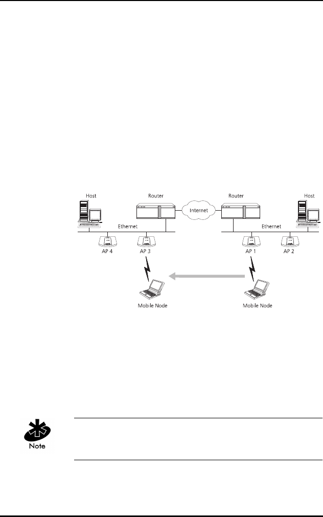
2.4 Mobile IP (roaming across routers) Description
The Spectrum24 WLAN supports Mobile IP (roaming
across routers) when properly configured as an MU and
configured to support Mobile IP (refer to appendix G
for configuration and setup). Also configure an Access
Point to properly pass through routing information. The
MU retains its IP address when configured for Mobile IP
and can:
•move from one IP subnet to another
•move from an Ethernet segment to a wireless LAN
•move from one Ethernet segment to another.
2.5 Power Management
The WLAN adapter provides two power-management
operation modes: Continuously Aware Mode (CAM)
requires the radio to remain on. Symbol does not
recommend CAM for battery powered devices.
A WLAN adapter operating in MicroAP mode functions in
CAM only. The ISA adapter functions in CAM only.

Wireless LAN Adapter
Spectrum24 Wireless LAN Adapter Product Reference Guide 9
Power Save Polling (PSP) mode allows the MU to conserve
power by suspending communication while still associated
with an AP. The AP saves data for the MU, which wakes at
given intervals to check for data. The WLAN adapter
drivers support dynamic power management, Algorithm
11 and 12 (refer to Appendix A for usage). Algorithm 11
varies the PSP parameter between 1 and 10 depending on
data traffic. Algorithm 12 switches the LAN adapter from
PSP mode to CAM, also depending on data traffic.
2.6 Card and Socket Services
The Spectrum24 WLAN adapter supports Card and Socket
services. In a DOS environment the WLAN adapter can
use Spectrum24 automatic configuration, hot insertion,
removal and power management features. Card and
Socket Service software packages providing these
features include SystemSoft, CardSoft or CardWizard
(not included).
The WLAN adapter supports Card and Socket Services
native to Microsoft Windows 95 but not in Windows NT.
2.7 Plug and Play
The Spectrum24 WLAN card Model 3020(PC Card) and
Model 3025 (ISA adapter) support Plug and Play systems.
This allows the PC to automatically recognize the WLAN
adapter, and configure the hardware interrupt, memory
and I/O addresses. This feature requires less user
interaction and minimizes hardware conflicts.
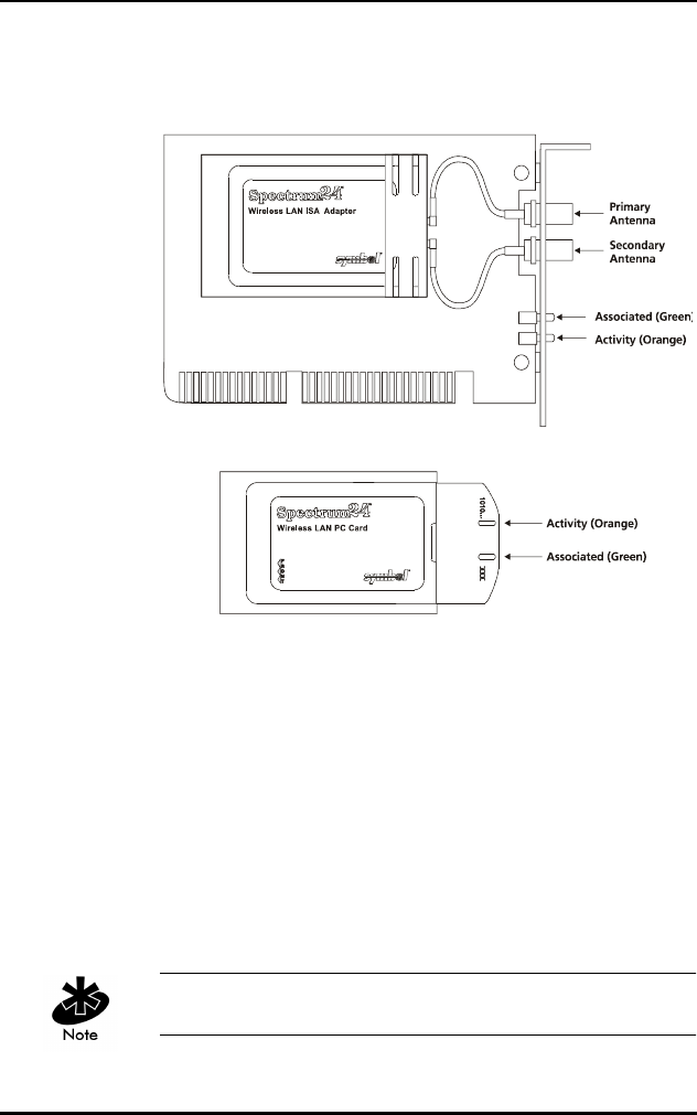
2.8 Spectrum24 Adapter LED Descriptions
Wireless LAN Adapter
10 Spectrum24 Wireless LAN Adapter Product Reference Guide
The WLAN adapter LEDs illuminate during connection
or data transfer to indicate the functional status of the
WLAN adapter.
PC Cards without end-cap antennas lack LEDs.
LEDs Mode LED Function
Associated As MicroAP The LED flashes to indicate a
powered MicroAP accepting
MUs.
As MU A solid LED indicates association
with an AP.
Activity As MicroAP A solid LED indicates data traffic
between the MicroAP and MU.
As MU A solid LED indicates
communication with the AP.

Spectrum24 Wireless LAN Adapter Product Reference Guide 11
Chapter 3 System Software
Supported
Spectrum24 WLAN adapters include drivers and
applications that support:
•Microsoft Windows 95
•Microsoft Windows NT 3.51 or 4.0
•DOS 3.3 or higher
•Microsoft Windows for Workgroups (v3.11)
•Novell Workplace v4.xx for DOS
•Novell Netware Client v2.x
•FTP PC/TCP v4.xx

System Software Supported
12 Spectrum24 Wireless LAN Adapter Product Reference Guide

Spectrum24 Wireless LAN Adapter Product Reference Guide 13
Chapter 4 Hardware Installation
Physical installation for the PC Card and ISA versions differ
for each system. Refer to the system manufacturer
documentation for specific information. Software
installation requires that the Installation and Utilities
diskette accompany the user guide.
4.1 Preparation
Before beginning the installation verify the hardware
package contains:
•Spectrum24 Wireless LAN Adapter
•plane antenna (for ISA adapter)
•end-cap antenna (for PC Card)
•installation diskette and utilities.
Verify the model indicated on the card and packaging
before use. Contact the Symbol Support Center if an item
is missing or not functioning.
4.2 Installing the PC Card
The Spectrum24 WLAN Adapter requires the following:
•a PC with a Type II PC Card slot
•a 3.5 inch floppy drive
•an available interrupt (IRQ)
•an available I/O port address
•Spectrum24 Driver installation Disk

Hardware Installation
14 Spectrum24 Wireless LAN Adapter Product Reference Guide
•an available upper memory range of 4Kb if setting up
for I/O mode
•an available upper memory range of 32Kb for setting
up memory mode
•a compatible Spectrum24 antenna
•10 to 16Kb available conventional or upper memory
space (terminate and stay resident driver only; does
not include network protocol stack).
Installation and removal methods vary for different host
devices. Refer to system documentation for information.
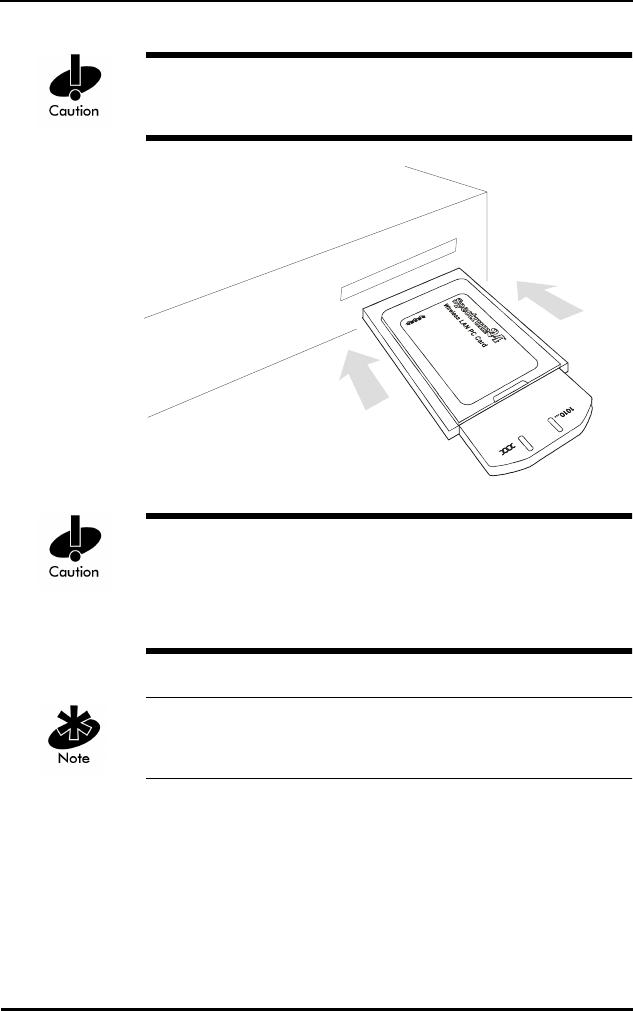
Avoid contact with liquids or abrasive materials.
1. Insert the PC Card into the PC slot. Arrows on the front
of the PC Card indicate the insertion point to the slot.
Slide it in until firmly seated.
Hardware Installation
Spectrum24 Wireless LAN Adapter Product Reference Guide 15
Align the card properly when inserting. Forcing the card
into the slot can damage the device or the card.
Keep the area around the end-cap antenna clear from
materials that could block radio transmission (i.e.
concrete, metals, and electrical systems). Inadequate
coverage can reduce network performance.
The end-cap antenna is available only for the PC
Card Model.
Hardware Installation
16 Spectrum24 Wireless LAN Adapter Product Reference Guide
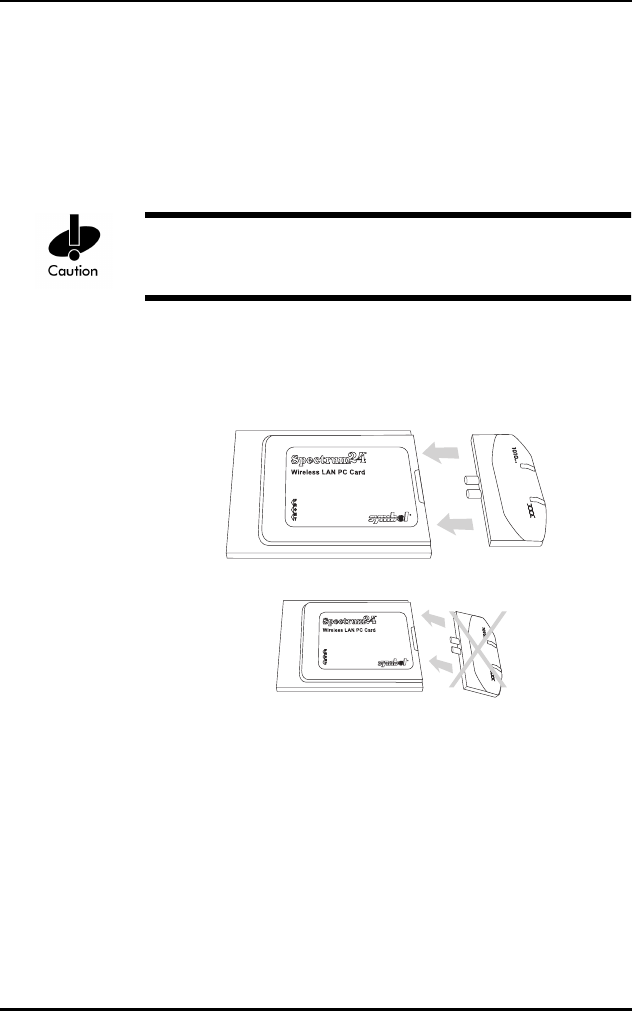
4.3 End-Cap Antenna Installation
To attach the end-cap antenna to the Spectrum24 PC
Card, grasp the PC Card at its end nearest the antenna
connector. Line up the antenna connectors with the PC
Card connectors. Keep antenna in line with the PC Card.
Tilting the antenna while trying to install or remove it can
cause the connectors to misalign and break.
Firmly press the antenna to the PC Card. A soft click
indicates the connectors have connected. Verify the PC
Card and antenna ends are flush.
4.4 End-Cap Antenna Removal
To remove the end-cap antenna, grasp the PC Card at
its end nearest the antenna connector. Grasp the antenna
at the end nearest the PC Card in the center above
the connectors.

Hardware Installation
Spectrum24 Wireless LAN Adapter Product Reference Guide 17
Do not press the buttons at the edges. They automatically
open.
Firmly pull the antenna from the PC Card. Keep the end-
cap in line with the PC Card.
Tilting the antenna while trying to install or remove it can
cause the connectors to misalign and break.
To ensure a reliable connection, attach the end-cap
antenna and PC Card connectors very securely. The
antenna connection to the card is stronger than the PC
Card connection in the host computer. Pulling the antenna
removes the PC Card from the computer without
disconnecting the antenna from the PC Card.
Flexing or tilting the antenna after attaching it to
the PC Card can break the antenna and/or the PC
Card connectors.
Hardware Installation
18 Spectrum24 Wireless LAN Adapter Product Reference Guide
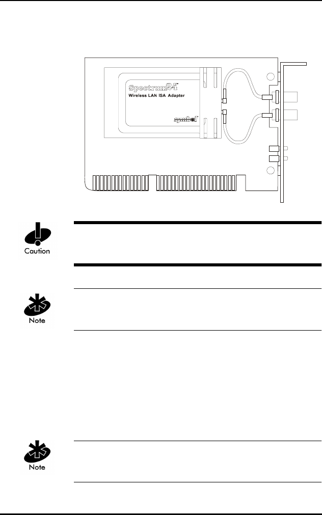
4.5 Installing the WLAN ISA Adapter
Use proper grounding for the environment when handling
computer components.
Symbol does not support this adapter yet under Windows
NT. This card runs in CAM only.
1. Power off the computer before installing the adapter.
2. If the system already has a PCMCIA adapter installed,
the WLAN adapter can function as a second
controller. Set the socket number, and the Plug and
Play option in the configuration file as required (refer
to Plug and Play section for configuration).
The WLAN adapter can exist only with systems using a
Cirrus Logic 6710 or 6720 bus interface controller.
Hardware Installation
Spectrum24 Wireless LAN Adapter Product Reference Guide 19
3. Remove the computer cover.
4. Locate an available ISA slot in the computer.
5. Remove the retaining screw and bracket for the slot.
6. Align adapter with the slot and insert firmly. Verify the
adapter seats into the slot evenly.
7. Verify that the BNC antenna connectors in the back of
the PC are exposed.
8. Secure the adapter to the chassis with a retaining screw.
9. Replace the computer cover.
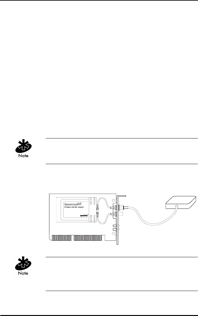
4.5.1 External Antenna Connection
The ISA version includes a plane antenna suitable for
most environments.
Install the plane antenna parallel to the ground for
optimal performance.
1. Attach antenna to the BNC antenna connector
as shown.
If using only a single antenna, attach it to the PRIMARY
antenna connector. Ensure the antenna is parallel to
the ground.

Hardware Installation
20 Spectrum24 Wireless LAN Adapter Product Reference Guide
2. Modify the DIVERSITY parameter in the appropriate
configuration file as follows
Table 4-1: DOS Configuration/Parameters For Antennae
Obtain additional or higher performance antennas from
Symbol. Contact a Symbol sales representative to order
the following models:
Configure Diversity (for dual antennae) by selecting the
Diversity check box from the Spectrum24 NT Installation
properties sheet or from the Symbol Spectrum24
Configuration properties sheet in Windows95. Refer to the
Windows 95/NT Driver Installation sections if necessary.
NDIS ODI
Single Diversity = N Diversity N
Dual Diversity = Y Diversity Y
additional plane antenna ML-2499-PSA1-00
single high-performance antenna ML-2499-HPA1-00
single rubber antenna ML-2499-APA1-00

Spectrum24 Wireless LAN Adapter Product Reference Guide 21
Chapter 5 Firmware Update
Occasionally the Spectrum24 PC Card and ISA adapter
firmware require updating for new features or performance
improvements. Firmware updates require:
•DOS (Version 3.3 or higher) bootable disk
•Spectrum24 PC Card Installation Disk.
To update the firmware:
1. Boot the machine from a DOS-bootable disk.
2. Remove the DOS-bootable disk and insert the
Spectrum24 ISA/PC Card Installation Disk 1.
3. Change to the \FIRMWARE sub-directory.
4. Enter the command: S_UPDATE (follow the instructions).
5. Remove the disk and restart the machine after
S_Update is complete.
If updating an ISA Plug and Play card, load SLAINIT.EXE
before running S_Update. Refer to the Plug and Play
section for SLAINIT.EXE installation. Symbol does not
support this Plug and Play ISA configuration yet under
Windows NT.
5.1 Verifying The Firmware Version
Load SLAINIT.EXE before installing ISA Plug and Play ISA
adapter. Refer to the Plug and Play section if necessary.
1. Boot the system to a DOS prompt.

Firmware Update
22 Spectrum24 Wireless LAN Adapter Product Reference Guide
2. Insert the Spectrum24 ISA/PC Card Installation
Disk 1.
3. From the DOS prompt change to the \FIRMWARE
sub-directory.
4. Enter the command (refer to Appendix E for more
information on S_VER use): S_VER.
5. Remove the disk and restart the machine if necessary
when S_VER is complete.

Spectrum24 Wireless LAN Adapter Product Reference Guide 23
Chapter 6 Windows 95/NT Driver
Installations
6.1 Windows 95 Driver Introduction
The Spectrum24 NDIS 3.x Driver provides access to a
Spectrum24 WLAN adapter under Windows 95. It supports
all transport protocols (i.e. NetBEUI, IPX/SPX, TCP/IP)
provided by Windows 95 on Spectrum24 PC Card, and
Plug and Play ISA adapters.
The Windows 95 support includes the Spectrum24 driver,
transport/API driver, driver extension service and the
network card installation disk. Locate the files on the
Spectrum24 ISA/PC Card Windows (32-bit) Installation
disk in \WIN95, and \WINNT\I386 sub-directories. The
distribution disk(s) contain the following files:
File Name Driver Description
SLANT.SYS Spectrum24 NDIS 3.x Driver
Version 4.x.
NETSLA.INF Spectrum24 NDIS 3.x Driver
Installation Script.
S24EVMON.EXE Spectrum24 Driver Extension Service.
S24TRANS.VXD Spectrum24 Transport/API driver
Version 4.x.
NETSLATR.INF Spectrum24 Transport/API driver
Installation Script.
INSTAL95.DOC Installation Instructions (Microsoft
Word 6.0/7.0).
INSTAL95.TXT Installation Instructions (DOS Text -
i.e. Microsoft Notepad).

Windows 95/NT Driver Installations
24 Spectrum24 Wireless LAN Adapter Product Reference Guide
6.2 New Features For v4.00
•supports IEEE 802.11 protocol
•supports 1 and 2 Mbps transfer rates
•supports Plug and Play ISA.
Refer to the Rate Control Table in the 1 and 2 Mbps
operation section of this document in order to set up the
adapter rate control.
6.3 Current Features in Windows 95
•Support for Windows95.
•Support for all Windows 95 transport protocols
(NetBEUI, IPX/SPX, TCP/IP, etc.) on both the
Spectrum24 PC Card and ISA adapter.
•Symbol supports all Spectrum24 PC Card and ISA
adapter firmware releases from Version 3.xx to
Version 4.xx.
•Update adapter firmware (under DOS) for new
features or performance improvements.
•Supports Symbol Spectrum24 (Spring) protocol.
6.4 Windows 95 Driver/Transport Updates
To update existing drivers, uninstall the previous
Spectrum24 or transport driver and reinstall
according to the Driver Installation and Transport
Installation procedures.

Windows 95/NT Driver Installations
Spectrum24 Wireless LAN Adapter Product Reference Guide 25
Symbol supports the following procedure only for driver
installations earlier than version 4.01. Using this
procedure on version 4.01 can cause unpredictable
behavior and even cause the operating system to fail. To
remove the Spectrum24 Driver and/or transport driver, run
the REMOVE.BAT file provided on the previous release
(version 4.00 or earlier) of the driver installation disk
(\WIN95\REMOVE.BAT). This removes the proper files
from the hard disk
6.5 Windows 95 Driver And Transport Uninstall
(Version 4.00 Or Earlier)
1. At the DOS prompt, enter:
REMOVE <parameter>
Where <parameter> is:
The Network Control Panel applet starts automatically,
after running the Remove.Bat file.
2. To remove the driver, select the Symbol Spectrum24
WLAN Adapter and click Remove.
3. To remove the transport, select the Symbol
Spectrum24 WLAN Transport and click Remove.
4. Click the OK button to exit and restart the system.
driver Removes the driver only.
transport Removes the transport only.
both Remove both the transport and driver.
Windows 95/NT Driver Installations
26 Spectrum24 Wireless LAN Adapter Product Reference Guide
To update the drivers, follow the Driver Installation
instructions.
6.6 Windows 95 Driver Installation
6.6.1 Preparation
Before installing a driver for Windows 95, verify or obtain
the following:
•Previous Spectrum24 Adapter and Transport have
been removed.
•PCMCIA support is enabled for non-Plug and
Play adapters
•200 KB available disk space
•Windows 95 installation media
•Spectrum24 network adapter installed
•Spectrum24 2Mb Driver and Utilities disk
•Install the Spectrum24 PC Card or ISA adapter (refer
to hardware installation for instructions on installing
the adapter).
For non Plug and Play adapters, enable Windows 95
PCMCIA support. Refer to Windows documentation for this
if necessary.
6.7 Windows 95 Retail Version
1. Install the Spectrum24 ISA adapter or the Spectrum24
PC Card.
2. Power up and boot the system.

Windows 95/NT Driver Installations
Spectrum24 Wireless LAN Adapter Product Reference Guide 27
3. When Windows 95 recognizes the Spectrum24 PC/
ISA/Plug and Play Card, the New Hardware Found
dialog box appears requesting the device driver
to install.
4. Place the Spectrum24 installation disk into the floppy
disk drive.
5. Select Driver from disk provided by hardware
manufacturer button, click the OK button.
6. When the Install From Disk dialog appears, (select the
default entry A:\) click the OK button.
7. Continue with the Windows 95 driver installation
instructions in this section.
6.8 Windows 95 OSR2 Version
1. Install the Spectrum24 ISA adapter or the Spectrum24
PC Card.
2. Power up and boot the system.
3. When Windows 95 recognizes the Spectrum24 PC/
ISA/Plug and Play Card, the Update Device Driver
Wizard dialog box appears requesting the device
driver to install. Select the Next button.
4. Place the Spectrum24 installation disk into the floppy
disk drive.
5. The Update Device Driver Wizard dialog displays
the device description. Click the Finish button
to continue.
6. When Windows displays “Windows found the
following updated driver adapter device Symbol
Spectrum24 WLAN Adapter” click the Finish button
to continue.
7. When Windows displays “please insert the disk
labeled ‘Symbol Spectrum24 ISA/PC Card Installation
Disk’” click OK.

Windows 95/NT Driver Installations
28 Spectrum24 Wireless LAN Adapter Product Reference Guide
8. When the Install From Disk dialog appears, (select the
default entry A:\) click the OK button.
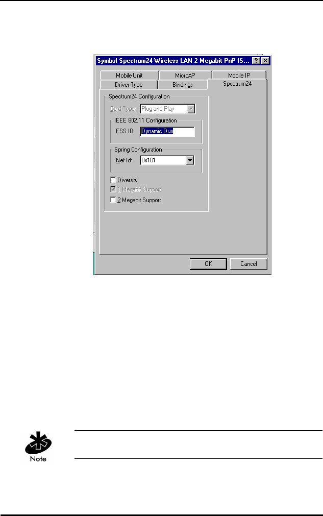
9. When the Symbol Spectrum24 Configuration dialog
box appears, select the Property Page that requires
modification. To change the adapter settings, select
the desired dialog. For the IEEE 802.11 protocol, set
the ESS ID to the desired network Access Point ESS ID.
For the Symbol Spring protocol, change the Net Id to
the desired network Access Point Net Id. When using a
WPOS/ISA adapter, change the Card Type dialog item
parameter to WPOS/ISA. This dialog item is not
available to the Plug and Play installation as shown.
Click the OK button to complete.
10. Insert the Windows 95 installation CD-ROM if
requested by Windows 95. If the Windows 95 .cab
files have been copied onto the hard disk, point the
system to the directory that contains them. When a
path has been entered to the Windows 95 installation
files, click the OK button.
11. When the System Settings Change dialog appears,
remove the Installation diskette from the floppy drive
and select the Yes button to restart the computer.
Windows 95/NT Driver Installations
Spectrum24 Wireless LAN Adapter Product Reference Guide 29
6.9 Windows 95 Setup
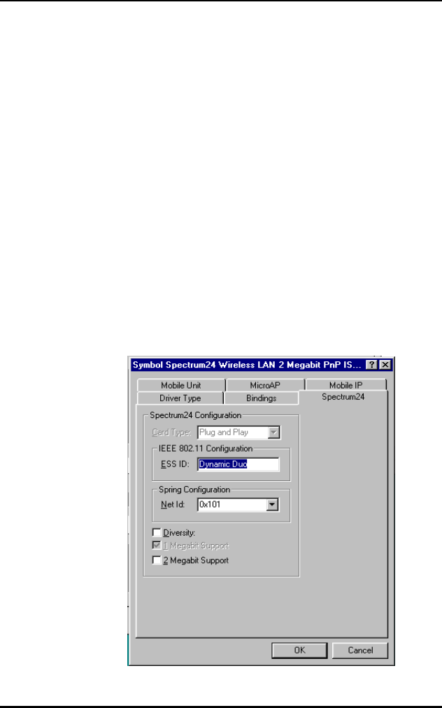
1. When the Symbol Spectrum24 Configuration dialog
box appears, select the Property Page that requires
modification. To change the adapter settings, select
the desired dialog . For the IEEE 802.11 protocol, set
the ESS ID to the desired network Access Point ESS ID.
For the Symbol Spring protocol, change the Net Id to
the desired network Access Point Net Id. When using a
WPOS/ISA adapter, change the Card Type dialog item
parameter to WPOS/ISA. This dialog item is not
available to the Plug and Play installation as shown.
Click the OK button to complete.
Select Diversity for dual antennae.
Windows 95/NT Driver Installations
30 Spectrum24 Wireless LAN Adapter Product Reference Guide
2. When the System Settings Change dialog appears,
remove the Installation diskette from the floppy drive
and select the Yes button to restart the computer.
6.10 Configuration
Modify the ESS ID or Net ID for the adapter so the network
can recognize the Mobile Unit. The default values are
“101” for the IEEE 802.11 ESS ID and 101 for the Symbol
Protocol Net ID.
To reconfigure the driver/adapter:
1. Open the Network applet from the Control Panel.
2. Select the Symbol Spectrum24 WLAN Adapter, and
select the Properties button.
3. When the Symbol Spectrum24 Configuration dialog
appears, select the appropriate tab to change the
adapter settings.

Windows 95/NT Driver Installations
Spectrum24 Wireless LAN Adapter Product Reference Guide 31
4. Select the dialog item to modify.
5. When all values have been changed, select the OK
button to save and exit or Cancel to abort and exit.
6. Restart the system for changes to take effect.
Refer to appendix A for the table containing a description
of the parameters and the range of acceptable values.
6.11 Windows NT 4.0/3.51 Driver Introduction
The Spectrum24 NDIS 3.x Driver provides access to a
Spectrum24 WLAN adapter under Windows NT 3.51/4.0
Workstation or Server. It supports all transport protocols
(i.e. NetBEUI, IPX/SPX, TCP/IP) provided by Windows
NT 3.51/4.0 on both the Spectrum24 PC Card and ISA
adapters. Install the driver during primary Windows
NT installation, or after Windows NT networking has
been installed. Locate the files for Windows NT 3.51
and Windows NT 4.0 in the Root directory and
\WINNT\I386 subdirectory. The distribution disk(s) include
the following:
File Name Driver Description
SLANT.SYS Spectrum24 NDIS 3.x Driver Version 4.x
OEMSETUP.INF Spectrum24 NDIS 3.x Driver Install
Script for Windows NT 3.51/4.0.
OEMNXP24.INF Spectrum24 NDIS 3.x Transport Install
Script for Windows NT 3.51/4.0.
S24EVMON.EXE Spectrum24 Driver Extension Service.
S24NT.DLL Spectrum24 Installation DLL Version 3.x.
S24NT.HLP Spectrum24 Installation DLL On-line
Help text file Version 3.x.

Windows 95/NT Driver Installations
32 Spectrum24 Wireless LAN Adapter Product Reference Guide
Symbol recommends updating the Spectrum24 PC/ISA
adapter to the latest firmware. Refer to the Firmware
update section for instructions.
6.12 New Features For v4.00
•supports IEEE 802.11 protocol.
•supports 1 and 2 Mbps transfer rates.
6.13 Current Features For NT
•The driver installation supports Windows NT 3.51 and
NT 4.0 Workstation and Server versions.
•Symbol supports all Windows NT transport protocols
(NetBEUI, IPX/SPX, TCP/IP, etc.) on both the
Spectrum24 PC Card and ISA adapter.
•Symbol fully supports all Spectrum24 PC Card and
ISA adapter firmware releases from Version 3.xx to
Version 4.xx are fully supported.
•Symbol fully supports all Spectrum24 diagnostic and
configuration utilities are supported. These utilities are
distributed on separate installation disks.
•Supports Symbol Spectrum24 protocol.
INSTALNT.DOC Installation instructions (Microsoft Word
6.0/7.0).
INSTALNT.TXT Installation instructions (DOS Text - i.e.
Microsoft Notepad).

Windows 95/NT Driver Installations
Spectrum24 Wireless LAN Adapter Product Reference Guide 33
6.14 Current Limitations For NT
•Perform adapter firmware update and preinstallation
PC/ISA card diagnostics (S24DIAG) under DOS. A
graphical interface version of site survey that runs on
Windows NT is available.
•Resource conflicts (i.e. Interrupt Number, I/O Base
Address, Memory Base Address) are not detected
during installation/configuration. Set up the
configuration so that it does not conflict with
other adapters.
•Installation disk does not support network card
autodetection. Requires manual installation of
the driver.
•Driver does not support Windows NT running on an
IBM notebook computer.
•Symbol does not support ISA Plug and Play.
6.15 Workstation/Server Primary Installation
6.15.1 Preparation
When installing the networking components and
Spectrum24 driver during Windows NT Workstation or
Server primary installation, verify or obtain the following:
•If using Spectrum24 ISA adapter, install prior to
enabling PCMCIA support.
•PCMCIA support is enabled (refer to Windows NT
documentation).
•Install the Spectrum24 PC Card before or after
PCMCIA support is enabled.
•400 KB of available disk space.
•The Spectrum24 Windows 95/NT Installation disk.

Windows 95/NT Driver Installations
34 Spectrum24 Wireless LAN Adapter Product Reference Guide
The driver installation disk does not include Spectrum24
utilities. S24INFO and S24UTIL are distributed separately.
6.16 Windows NT 4.0
1. Power up the system, when the Windows NT Setup
dialog appears, click the Select from list button for
Network Adapters selection.
2. Select Network Adapter dialog appears, click the
Have Disk button.
3. Insert the Spectrum24 ISA/PC Windows 95/NT
Installation diskette into the floppy drive and select the
default path to the driver files (A:) by clicking OK.
4. When the Select OEM Option dialog appears, select
the Symbol Technologies Spectrum24 Adapter and
click OK.
5. At the Windows NT Setup dialog, click Next
to continue.
6. When the Windows NT Setup dialog appears for
protocol installation, select the appropriate Network
Protocols and Network Services. Click Next, and Next
again to start the network installation.
7. Select Next to start the installed network configuration.
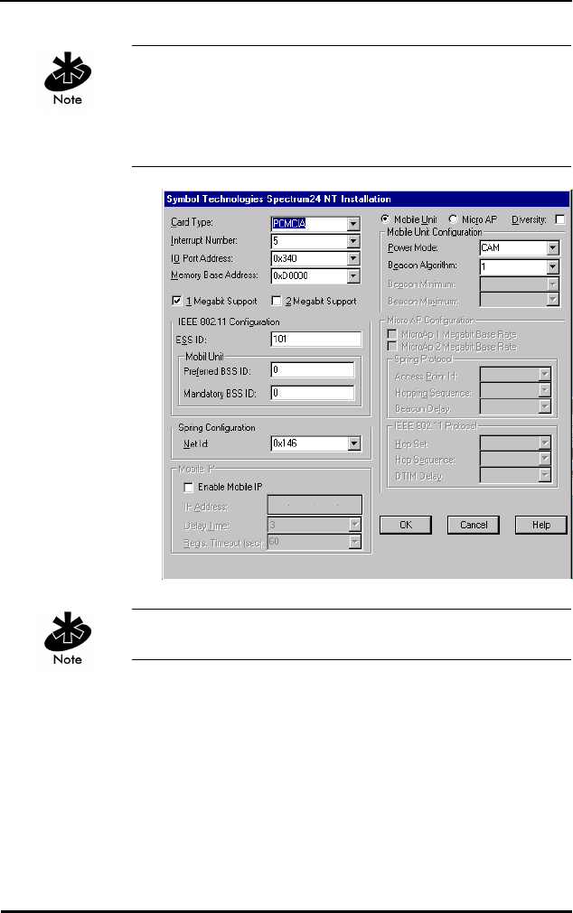
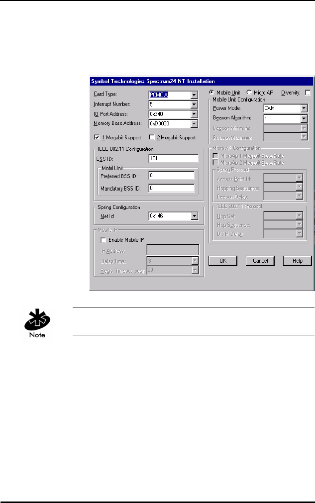
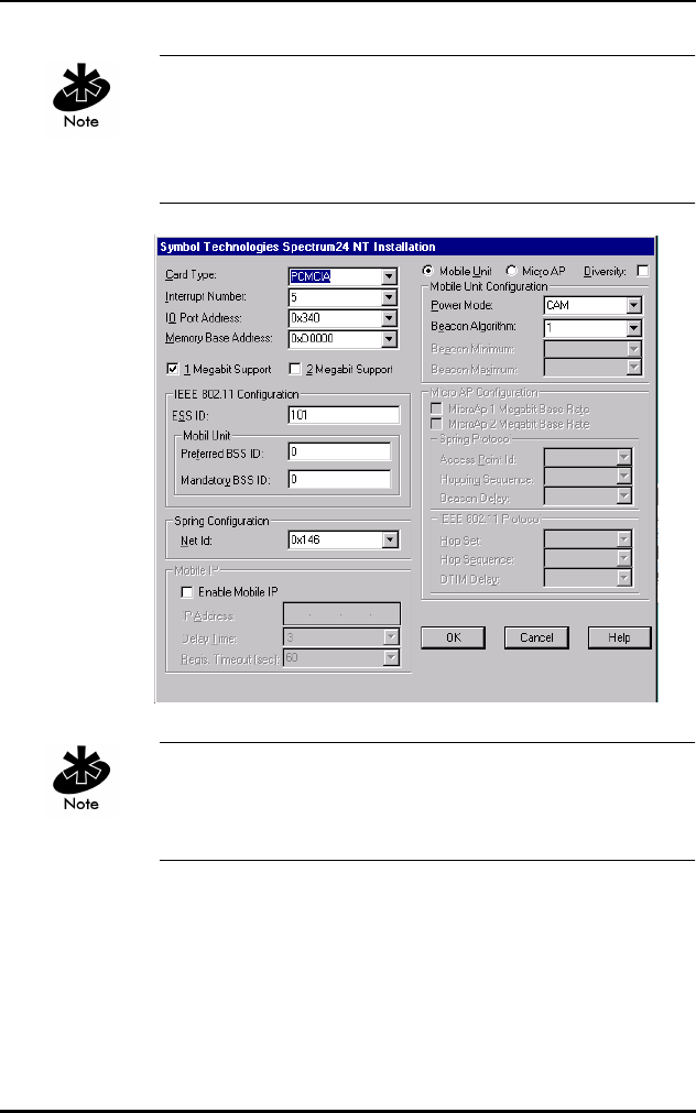
8. When the Symbol Technologies Spectrum24 NT
Installation dialog appears, set the appropriate driver/
adapter configuration parameters. For the Symbol
Spring protocol, change the Net Id to the Access Point
Net Id. For the IEEE 802.11 protocol, change the ESS
ID to the Access Point ESS ID. For the WPOS/ISA bus
card, select the WPOS/ISA Adapter Type. Click OK
when complete or Cancel to use default values.
Windows 95/NT Driver Installations
Spectrum24 Wireless LAN Adapter Product Reference Guide 35
Interrupt Number, I/0 Port Address and Memory Base
Address might need modification to fit system needs.
Check the system resources for nonconflicting settings
before proceeding with installation.
Select Diversity for dual antennae.
9. Modify any protocol specific parameters that Windows
NT requires to continue.
10. At the Windows NT Setup Wizard dialog, select Next
to continue.
11. Enter the Computer Name, Workgroup or Domain for
this computer and select Next.

Windows 95/NT Driver Installations
36 Spectrum24 Wireless LAN Adapter Product Reference Guide
12. At the Windows NT Setup Wizard dialog , select Finish
to complete the installation.
13. The Windows NT Setup Wizard continues to setup
other operating system components.
14. At the Reboot System dialog, select restart to reboot
the system.
15. Remove the Spectrum24 ISA/PC Windows 95/NT
Installation disk.
6.17 Windows NT 3.51
1. Power up the system and when the Network Adapter
Card Detection dialog appears, select Continue to
manually install the driver. Select Continue when the
secondary dialog appears.
2. Add Network Adapter dialog appears, select the drop
down the selection box, proceed to the bottom of the
list, and select <Other> Requires disk from
manufacturer from the Network Adapter Card list, and
select Continue.
3. Insert the Spectrum24 ISA/PC Windows 95/NT
Installation diskette into the floppy drive and select the
default path to the driver files (A:\) by selecting the
OK button.
4. Select OEM Option dialog appears, select Symbol
Technologies Spectrum24 Adapter and select the OK
to accept the selection.
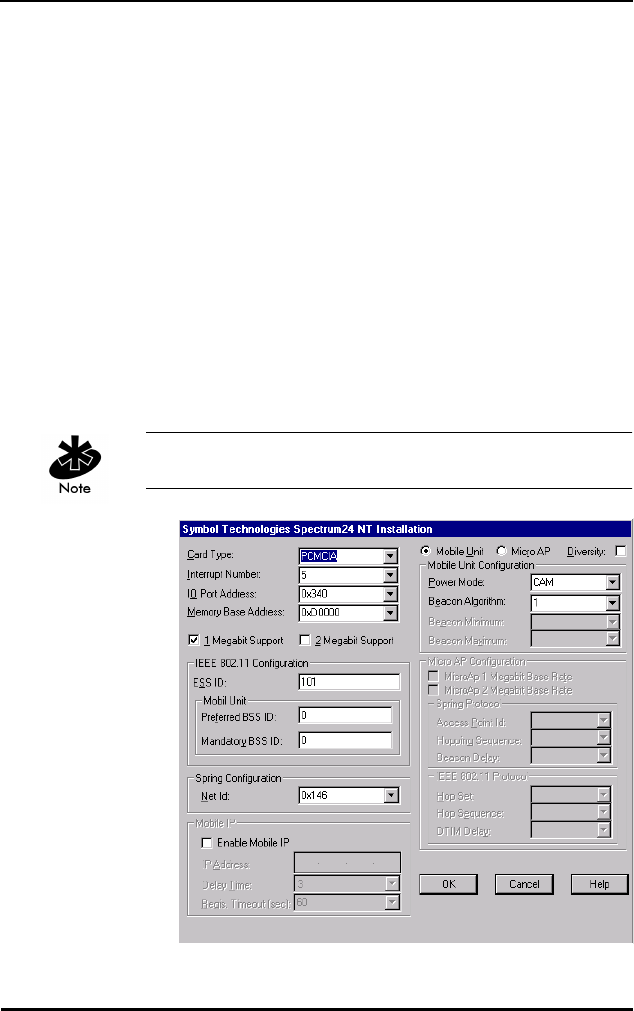
5. When the Symbol Technologies Spectrum24 NT
Installation dialog appears, set the appropriate driver/
adapter configuration parameters. For the Symbol
Spring protocol, change the Net Id to the Access Point
Net Id. For the IEEE 802.11 protocol, change the ESS
ID to the Access Point ESS ID. For the WPOS/ISA bus
card, select the WPOS/ISA Adapter Type. Click OK
when complete or Cancel to use default values.
Windows 95/NT Driver Installations
Spectrum24 Wireless LAN Adapter Product Reference Guide 37
6. Interrupt Number, I/0 Port Address and Memory Base
Address might need modification to fit the system
needs. Check the system resources for non-conflicting
settings before proceeding with installation
Select Diversity for dual antennae.
7. Modify any protocol specific parameters that Windows
NT requires to continue.
8. When the Network Settings dialog appears, select OK
to accept the changes.
9. If a warning appears that the network could not start
properly, select OK button. If a Network Malfunction
warning message dialog appears, select No. The
network starts up properly when the machine reboots.

Windows 95/NT Driver Installations
38 Spectrum24 Wireless LAN Adapter Product Reference Guide
10. Remove the Spectrum24 ISA/PC Windows 95/NT
Installation disk and follow all remaining instructions.
6.18 First Time Network Installation
If the networking components were not installed during the
primary installation process, install them using the
Network Control Panel applet. Users need Administrator
group privileges to install network components.
6.19 Windows NT 4.0
1. Boot and login to the system.
2. Open the Network applet from the Control Panel.
3. The Network Configuration dialog prompts for
Windows NT Networking installation, click on the Yes
button. Select the Wired to the network check box
when the Network Setup Wizard dialog appears and
click the Next button.
4. When the Network Setup Wizard dialog queries
for a network installation, click the Select from list…
button.
5. From the Select Network Adapter dialog, click the
Have Disk… button.
6. Insert the Spectrum24 ISA/PC Windows 95/NT
Installation into the floppy drive and select the default
path to the driver files (A:) by clicking the OK button.
7. Select the Symbol Technologies Spectrum24 WLAN
adapter and click the OK button.
8. When the Network Setup Wizard dialog returns, click
the Next button to continue.
9. The Network Setup Wizard dialog displays protocol
choices. Select all that apply, click the Next button
Windows 95/NT Driver Installations
Spectrum24 Wireless LAN Adapter Product Reference Guide 39
to continue. Click the Next button through the next two
dialogs.
10. The Network Setup Wizard displays a dialog
requesting some Windows NT files. Enter the full path
to the Windows NT distribution files (i.e. A:\ for floppy
based installation), and click the Continue button.
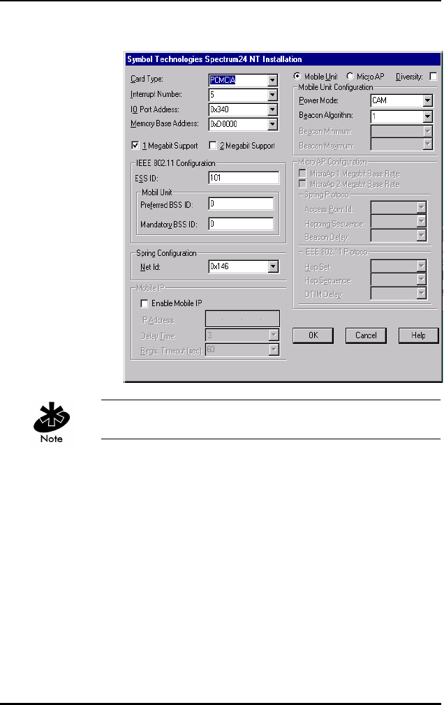
11. When the Symbol Technologies Spectrum24 NT
Installation dialog appears, set the appropriate driver/
adapter configuration parameters. For the Symbol
Spring protocol, change the Net Id to the Access Point
Net Id. For the IEEE 802.11 protocol, change the ESS
ID to the Access Point ESS ID. For the WPOS/ISA bus
card, select the WPOS/ISA Adapter Type. Click OK
when complete or Cancel to use default values.
Select Diversity for dual antennae.

Windows 95/NT Driver Installations
40 Spectrum24 Wireless LAN Adapter Product Reference Guide
Interrupt Number, I/0 Port Address and Memory Base
Address might need modification to fit the system needs.
Check the system resources for non-conflicting settings
before proceeding with installation
12. The Network Setup Wizard displays the network
binding dialog and allows the user to change the
binding to the various Windows NT services. Making
modifications to this dialog is not necessary for a
successful Spectrum24 installation. Click the Next
button to continue.
13. The Network Setup Wizard displays the Start Network
dialog. Click the Back button to return and modify
previous dialogs. Otherwise, start the network by
clicking the Next button.
14. The Network Setup Wizard displays the Network
Identification dialog. Type the Computer Name,
Workgroup or Domain for this computer and click the
Next button.
15. The Network Setup Wizard displays the final setup
dialog, click the Finish button to complete the
setup procedure.
16. The Network Settings Change dialog displays and
requests a system shutdown. Click the Yes button
to reboot.
17. Remove the Spectrum24 ISA/PC Windows 95/NT
Installation disk.
6.20 Windows NT 3.51
1. Boot and login to the system.
2. Open the Network applet from the Control Panel.

Windows 95/NT Driver Installations
Spectrum24 Wireless LAN Adapter Product Reference Guide 41
3. The Network Settings dialog prompts for Windows NT
Networking installation, click the Yes button to
continue. When prompted, enter the full path to the
Windows NT distribution files (i.e. A:\ for floppy based
installation), and click the Continue button.
4. When the Network Adapter Card Detection dialog
appears, click the Do Not Detect button to manually
install the driver. Click the Continue button when the
next dialog appears.
5. At the bottom of the Add Network Adapter list box,
click <Other> Requires disk from manufacturer from
the Network Adapter Card list and click the Continue
button. Insert the Spectrum24 ISA/PC Windows 95/NT
Installation diskette into the floppy drive and select the
default path to the driver files (A:\) by clicking the OK
button.
6. When the Select OEM Option dialog appears, select
the Symbol Technologies Spectrum24 WLAN Adapter
option. Click the OK button to continue.
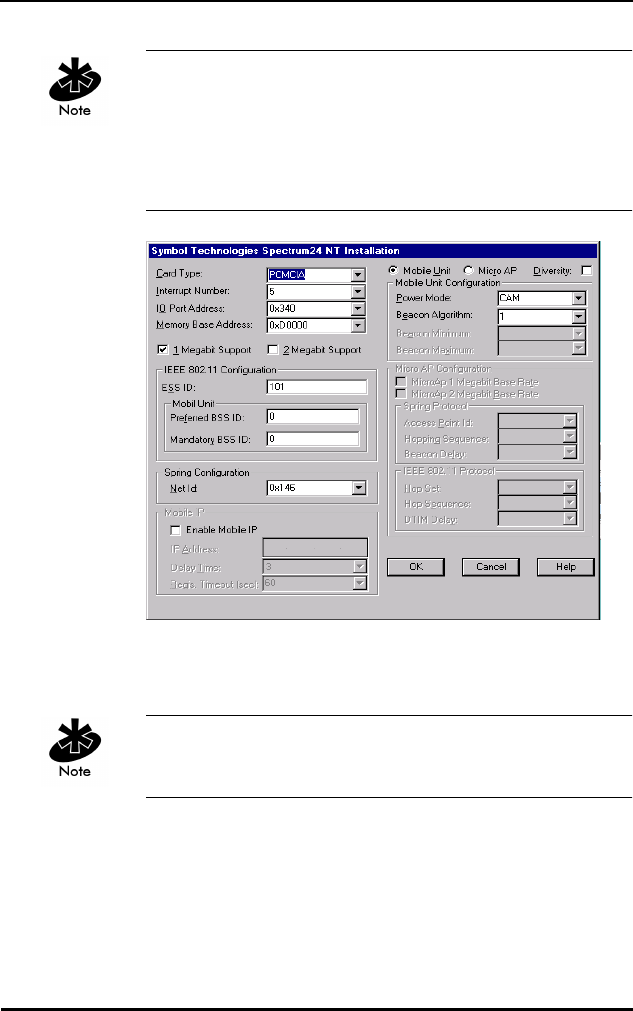
7. When the Symbol Technologies Spectrum24 NT
Installation dialog appears, set the appropriate driver/
adapter configuration parameters. For the Symbol
Spring protocol, change the Net Id to the Access Point
Net Id. For the IEEE 802.11 protocol, change the ESS
ID to the Access Point ESS ID. For the WPOS/ISA bus
card, select the WPOS/ISA Adapter Type. Click the OK
button when complete or the Cancel button to use
default values.
Interrupt Number, I/0 Port Address, and Memory Base
Address might need modification to fit the needs of the
system. Check the system resources for nonconflicting
settings before proceeding with the installation.
Windows 95/NT Driver Installations
42 Spectrum24 Wireless LAN Adapter Product Reference Guide
Select Diversity for dual antennae.
8. From the Windows NT Setup dialog, select any
applicable transport protocols. Click the Continue
button to proceed.
9. When prompted for protocol specific configuration,
click the Symbol Spectrum24 Adapter in the
appropriate dialogs.
10. Dialogs displays based on any protocol selections
made. Proceed by clicking the Continue button for
each dialog encountered.
11. After the Network Settings dialog appears, click
Bindings to view the current protocol bindings.

Windows 95/NT Driver Installations
Spectrum24 Wireless LAN Adapter Product Reference Guide 43
Use the Enable/Disable buttons to enable/disable
the appropriate bindings, click the OK button
when complete.
12. Click the OK button to exit the Network Control
Panel applet.
13. A prompt requests configuration of the bound
protocol stacks. Click the Symbol Spectrum24
WLAN Adapter from the Adapter list and enter
appropriate values.
14. If a warning appears that the network could not be
started properly, click the OK button to continue. The
network starts after reboot. If a Network Malfunction
warning message dialog appears, click the No button
to continue. The network starts properly after
rebooting the machine.
15. Remove the Spectrum24 ISA/PC Windows 95/NT
Installation disk and follow all remaining instructions
to complete the installation.
6.21 Existing Network Installation
When using a previous driver version, remove the driver
before installing the new one. Use the Network Control
Panel applet Remove function to remove the driver and
reboot the system. Follow the Driver Installation procedure
below. Install only one Spectrum24 PC Card in a single
machine. The Spectrum24 PC Card can coexist with a
second non-Spectrum24 LAN adapter. Ensure proper
protocol stack bindings (i.e. some stacks bind to
both adapters but cannot function properly).
Administrator group privileges are required to install
network components.

Windows 95/NT Driver Installations
44 Spectrum24 Wireless LAN Adapter Product Reference Guide
6.22 Windows NT 4.00
1. Boot and log into the system.
2. Open the Network applet from the Control Panel.
3. Click Adapters, and click the Add button.
4. When the Select Network Adapter dialog appears,
click the Have disk… button.
5. Insert the Spectrum24 ISA/PC Windows 95/NT
Installation diskette into the floppy drive and select
the default path to the driver files (A:) by clicking the
OK button.
6. Select the Symbol Technologies Spectrum24 WLAN
Adapter, and click the OK button to continue.
7. When the Symbol Technologies Spectrum24 NT
Installation dialog appears, set the appropriate driver/
adapter configuration parameters.
– For the Symbol Spring protocol, change the Net Id
to the Access Point Net Id.
– For the IEEE 802.11 protocol, change the ESS ID
to the Access Point ESS ID.
– For the WPOS/ISA bus card, select the WPOS/ISA
Adapter Type.
8. Click the OK button when complete or the Cancel
button to use default values.
Windows 95/NT Driver Installations
Spectrum24 Wireless LAN Adapter Product Reference Guide 45
Select Diversity for dual antennae. Interrupt Number, I/0
Port Address, and Memory Base Address might need
modification to fit the system needs. Check the system
resources for nonconflicting settings before proceeding
with installation.
9. When the Network dialog box appears, click the
Protocols tab.
Verify that Symbol Technologies Spectrum24 NDIS 3.0
Packet Driver Appears under Network Protocols.
10. Select Add.
11. When the Network Protocol list box appears, select the
desired protocol.
12. Click OK.

Windows 95/NT Driver Installations
46 Spectrum24 Wireless LAN Adapter Product Reference Guide
13. When Windows displays “Setup Needs To Copy Some
Windows NT files”. Enter the full path to the Windows
NT distribution files (i.e. A:\ for floppy based
installation), and click the Continue button.
14. Click the Bindings button to view the current protocol
stack bindings. Click the Enable/Disable buttons to
enable or disable the appropriate bindings.
15. Click the Close button to exit the Network settings.
16. If prompted to configure the bound protocol stacks
at this time, select the Symbol Spectrum24
WLAN Adapter from the Adapter list and enter
appropriate values.
17. The Network Settings Change dialog displays and
requests a system shutdown. Click the Yes button
to reboot.
18. Remove the Spectrum24 ISA/PC Windows 95/NT
Installation disk.
6.22.1 Windows NT 3.51
1. Boot and log into the system.
2. Open the Network applet from the Control Panel.
3. When the Network Settings dialog appears, click the
Add Adapter button.
4. When the Add Network Adapter dialog appears, click
<Other> Requires disk from manufacturer selection
and click the Continue button.
5. Insert the Spectrum24 ISA/PC Windows 95/NT
Installation diskette into the floppy drive and select
the default path to the driver files (A:\) by clicking the
OK button.
6. Select the Symbol Technologies Spectrum24 WLAN
Adapter and click the OK button.

Windows 95/NT Driver Installations
Spectrum24 Wireless LAN Adapter Product Reference Guide 47
7. When the Symbol Technologies Spectrum24 NT
Installation dialog appears, set the appropriate driver/
adapter configuration parameters. For the Symbol
Spring protocol, change the Net Id to the Access Point
Net Id. For the IEEE 802.11 protocol, change the ESS
ID to the Access Point ESS ID. For the WPOS/ISA bus
card, select the WPOS/ISA Adapter Type. click the OK
button when complete or the Cancel button to use
default values.
Verify in the Installed Network Software list that Symbol
Technologies Spectum24 NDIS and Spectrum24 Symbol
Technologies WLAN are present. If not restart installation
8. Click Add Software button.
9. Add Network Software dialog list appears.
10. Select the desired Network Protocol. Click Continue.
11. The Windows NT Setup dialog box requests Windows
NT distribution files. Enter the full path to the location
(i.e. E:\i386 for a CD Rom installation) of these files.
Click Continue.
Windows 95/NT Driver Installations
48 Spectrum24 Wireless LAN Adapter Product Reference Guide
Interrupt Number, I/0 Port Address, and Memory Base
Address might need modification to fit the system needs.
Check the system resources for nonconflicting settings
before proceeding with installation.
Verify that Symbol Spectrum24 WLAN Adapter is
selected before updating bindings. Select Diversity for
dual antennae.
12. Click Bindings to view the current protocol stack
bindings. Use the Enable/Disable buttons to enable or
disable the appropriate bindings (enabled bindings
have a yellow light bulb next to them).
13. Click OK to exit the Network Settings dialog.

Windows 95/NT Driver Installations
Spectrum24 Wireless LAN Adapter Product Reference Guide 49
14. If prompted to configure the bound protocol
stacks at this time, click the Symbol Spectrum24 WLAN
Adapter from the Adapter list and enter appropriate
values.
15. The Network Settings Change dialog displays and
requests a system shutdown. Click the Restart Now
to reboot.
16. Remove the Spectrum24 ISA/PC Windows 95/NT
Installation disk.
6.23 Windows NT Driver Update
Use the Update function in the Network Control Panel
applet to update the Spectrum24 files on the hard disk.
The existing driver/adapter configuration does not change.
6.24 Windows NT 4.0
1. Boot and log into the system.
2. Open the Network Control Panel applet.
3. Select the Adapters tab.
4. Select the Symbol Spectrum24 WLAN Adapter, and
click the Update button to continue.
5. Insert the Spectrum24 ISA/PC Windows 95/NT
Installation diskette into the floppy drive and select
the default path to the driver files (A:\) by clicking the
OK button.
6. When prompted, remove the installation disk.
7. Click the OK button.
8. Click the Close button to exit the Network applet.
9. Click the Yes button to restart the system.

Windows 95/NT Driver Installations
50 Spectrum24 Wireless LAN Adapter Product Reference Guide
10. Remove the Spectrum24 ISA/PC Windows 95/NT
Installation disk.
6.25 Windows NT 3.51
1. Boot and log into the system.
2. Open the Network icon from the Control Panel.
3. Select the Symbol Spectrum24 WLAN Adapter, and
click the Update button to continue.
4. Insert the Spectrum24 ISA/PC Windows 95/NT
Installation diskette into the floppy drive and select
the default path to the driver files (A:\) by clicking the
OK button.
5. When prompted, remove the installation disk.
6. Click the OK button twice to exit the Network applet.
7. Click the Restart Now button to restart the system.
8. Remove the Spectrum24 ISA/PC Windows 95/NT
Installation disk.
6.25.1 Network Adapter Configuration
Modify the Card Type and the ESS_ID or Net_ID. If there
are resource conflicts, change one or more of the
following: Interrupt Number, I/O Port Address, and
Memory Base Address. To reconfigure the driver/adapter
do the following:
6.26 Windows NT 4.00
1. Boot and log into the system.
2. Open the Network icon from the Control Panel.
3. Select the Symbol Spectrum24 WLAN Adapter, and
click the Configure button.

Windows 95/NT Driver Installations
Spectrum24 Wireless LAN Adapter Product Reference Guide 51
4. Select Adapters, select the Symbol Spectrum24 WLAN
Adapter and click the Properties button.
5. When the Symbol Technologies Spectrum24 NT
Installation dialog appears, select a field and use the
arrow buttons to display a list of valid values or use the
keyboard to enter a value.
Enter values with a leading ‘0x’ representing hex-decimal
numbers with leading ‘0x’ when using keyboard entry.
6. When all values have been changed, click the OK
button to save and exit. Click the Cancel button to
abort and exit.
6.27 Windows NT 3.51
1. Boot and log into the system.
2. Open the Network icon from the Control Panel.
3. Select the Symbol Spectrum24 WLAN Adapter, and
click the Configure button.
4. When the Symbol Technologies Spectrum24 NT
Installation dialog appears, select a field and use the
arrow buttons to display a list of valid values or use the
keyboard to enter a value.
Enter values displayed with a leading ‘0x’ representing
hex-decimal numbers with the leading ‘0x’ when using
keyboard entry.
5. When all values have been changed, click the OK
button to save and exit. Click the Cancel button to
abort and exit.

Windows 95/NT Driver Installations
52 Spectrum24 Wireless LAN Adapter Product Reference Guide
Refer to appendix B for the table containing a description
of the parameters and the range of acceptable values.

Spectrum24 Wireless LAN Adapter Product Reference Guide 53
Chapter 7 DOS/Windows For
Workgroups Driver
Installation
7.1 Preventing Memory Range Conflicts
The ISA Plug and Play WLAN card requires users to load
SLAINIT.EXE prior to loading the driver or updating the
firmware. Ensure the firmware is up to date. Refer to
firmware update section for instructions on firmware
version verification.
1. To prevent conflicts with other devices, use an
extended memory manager (i.e., EMM386, etc.).
Exclude the upper memory block where the adapter
resides. Modify the memory manager device line in
CONFIG.SYS, if the adapter has a memory location
starting at 0xD000 operating in memory mode and
EMM386 is being used.
– For memory mode operation:
[DEVICE]=[path]EMM386.EXE X=D000-D7FF
– For I/O mode operation:
[DEVICE]=[path]EMM386.EXE X=D000-D0FF
2. Modify the network configuration to include the
memory range used by the WLAN adapter.
– Exclude a 4 KB memory range for I/O Mode
operation.

DOS/Windows For Workgroups Driver Installation
54 Spectrum24 Wireless LAN Adapter Product Reference Guide
– Exclude a 32 KB memory range for memory
mode operation.
Refer to the Network Configuration for further details.
Memory manager parameter settings vary. Refer to the
memory manager software documentation
3. Reboot the system.
Refer to Vendor docmentation for setup and installation of
third-party network software and drivers.
7.2 Spectrum24 Automated Driver Installation
The installation program copies the ODI driver and
configuration files for the Novell Client to the hard
drive. The installation program can modify
AUTOEXC.BAT. The automatic installation program
assumes default settings. To control value selection,
use the manual installation option.The installation
program also includes diagnostics functions for testing
the adapter. For additional information, refer to the
README.TXT file provided on the DOS (16 bit) Drivers
and Utilities diskette.
•For ODI, select ODI Installation from the main menu.
This allows an automatic or manual driver installation
and configuration.
•For NDIS, select Driver Installation Instructions from
the main menu. For installation program overview,
select Help from the main menu and select Installation
Overview. To control value selection, use the manual
installation.

DOS/Windows For Workgroups Driver Installation
Spectrum24 Wireless LAN Adapter Product Reference Guide 55
A default installation is assumed for all driver installations.
All references made are to default directories for
all installations.
1. Power up the system to a DOS prompt.
2. Insert the Drivers and Utilities Installation Diskette into
the floppy drive.
3. Change the drive and path to the location of the
Drivers and Utilities diskette.
4. Press the Enter key.
5. Type Install.
6. Follow the instructions from the installation program.
Reboot the system when prompted.
If the automatic installation program was not used, copy
the files as needed (LSL.COM, SLAINIT.EXE,
SL8ODIPC.COM) from the Drivers and Utilities Installation
diskette to the appropriate directory on the hard disk.
7.3 NDIS Manual Installation
For NDIS, MUs require the radio device driver
SL8NDIS.EXE. A protocol manager (e.g. PROTMAN) binds
NDIS drivers to the protocol stack. A network bind (e.g.
NETBIND) program binds all the network stack
components. NDIS loads as a system block device driver
NDIS drivers install in the CONFIG.SYS.
The NDIS driver supports network configurations
compatible with the NDIS v2.01 specification NDIS
configured systems require the following:

DOS/Windows For Workgroups Driver Installation
56 Spectrum24 Wireless LAN Adapter Product Reference Guide
•SL8NDIS.EXE - The Spectrum24 radio device driver.
•PROTMAN - A protocol manager to bind NDIS drivers
to the protocol stack.
•NETBIND - a network bind program for all network
stack components.
•Other protocol drivers as required
Locate NDIS network parameters in Protocol.ini. Edit
Protocol.ini using an ASCII text editor. The following
example assumes a default installation of the third party
network software. Refer to individual vendor
documentation for setup of specific network software being
used. [PATH] refers to the location of files on the hard
drive. If the automatic installation program was not used,
copy the files as needed (PROTMAN.DOS, SL8NDIS.EXE,
NETBIND.COM) from the Drivers and Utilities Installation
diskette to the appropriate directory on the hard disk.
7.4 Modifying Config.sys
Verify the following lines in Config.sys are present:
DEVICE=[PATH]\PROTMAN.DOS /C:\
DEVICE=[PATH]\SL8NDIS.exe
•other protocol drivers as required
7.5 Modifying Autoexec.bat
In AUTOEXEC.BAT verify the following:
[PATH]\NETBIND.COM

DOS/Windows For Workgroups Driver Installation
Spectrum24 Wireless LAN Adapter Product Reference Guide 57
7.6 Modifying Protocol.ini
Modify PRTOCOL.INI to include:
[sample PROTOCOL.INI entry for SYMBOL NDIS driver]
[protman]
DriverName=SYMBOL$
[SYMBOLNET]
DRIVERNAME=SYMBOL$
IOADDRESS=0x300
INT=5
MEM=0xD000
ESS_ID=101
DIVERSITY=NO
•other Keywords as required from appendix D.
[Other protocol driver sections as required]
7.7 ODI Manual Installation
For ODI, MUs require a Multiple Link Interface Driver
(MLID) called SL8ODIPC.COM. SL8ODIPC.COM is the
radio device driver. The multiple stacks the MU uses (e.g.
TCP/IP) are known as the Multiple Protocol Interfaces
(MPI). A link support layer (LSL) program provides the link
between MLID and MPI. ODI loads as a Terminate and
Stay Resident (TSR) program. ODI program files run from
the command line or as part of a batch file.
Edit ODI binding and configuration information stored in
NET.CFG with an ASCII text editor using the appropriate
keywords found in Appendix D. The following examples
assume a default installation of third party network

DOS/Windows For Workgroups Driver Installation
58 Spectrum24 Wireless LAN Adapter Product Reference Guide
programs. [PATH] refers to the location of files on the hard
drive. If the automatic installation program was not used,
copy the files as needed (LSL.COM, SL8ODIPC.COM, )
from the Drivers and Utilities Installation diskette to the
appropriate directory on the hard disk.
7.8 Modifying Autoexec.bat
Modify AUTOEXEC.BAT to include the following:
[PATH]\LSL
[PATH]\SLAINIT (If using an ISA card)
[PATH]\SL8ODIPC
•other protocol drivers as required.
7.9 Modifying Net.cfg
With an ASCII text editor, create NET.CFG in the network
directory. Include the following statements:
LINK DRIVER SLAODI
FRAME ETHERNET_II
MODE IO
IOADDRESS 300
INTERRUPT 5
ESS_ID 101
Verify the values do not conflict with other system
interrupts, I/O and memory ranges. Refer to Appendix D
for a detailed description of DOS keyword definitions.

DOS/Windows For Workgroups Driver Installation
Spectrum24 Wireless LAN Adapter Product Reference Guide 59
7.10 Keyword usage
Certain keywords enable or disable features, modes
and usage of the Spectrum24 adapter in different
environments. Refer to Appendix D for a detailed definition
of all DOS keywords.
7.11 Enabling Plug and Play
In both cases set the driver keyword PNP to YES. Verify that
the keywords Cardservices and Socketservices are not
present or are set to NO.
For ODI, in NET.CFG enter:
PNP YES
CARDSERVICES NO
SOCKETSERVICES NO
For NDIS, in PROTOCOL.INI enter:
PNP=YES
CARDSERVICES=NO
SOCKETSERVICES=NO

DOS/Windows For Workgroups Driver Installation
60 Spectrum24 Wireless LAN Adapter Product Reference Guide
The ISA Plug and Play WLAN card requires users to load
SLAINIT.EXE prior to loading the driver or updating the
firmware. For ODI, from the command line or in a batch
file load the following:
LSL.COM
SLAINIT.EXE
SL8ODIPC.COM
•other protocol drivers as required.
For NDIS, in the config.sys file include:
[DEVICE]=[PATH]\PROTMAN.DOS
[DEVICE]=[PATH]\SLAINIT.EXE
[DEVICE]=[PATH]\SL8NDIS.EXE
•other protocol drivers as required.
7.12 Enabling CardServices
Load SLAINIT.EXE prior to loading the driver in order to use
Card and Socket Services with the PCMCIA Adapter card.
Using Card and Socket Services allows Hot Swapping the
PCMCIA Adapter card. It also provides protection against
resource conflicts.

DOS/Windows For Workgroups Driver Installation
Spectrum24 Wireless LAN Adapter Product Reference Guide 61
For ODI, from the command line or in a batch file enter:
LSL.COM
SLAINIT.EXE
SL8ODIPC.COM
•other protocol drivers as required.
For NDIS, in config.sys enter:
[DEVICE]=[PATH]\PROTMAN.DOS
[DEVICE]=[PATH]\SLAINIT.EXE
[DEVICE]=[PATH]\SL8NDIS.EXE
•other protocol drivers as required.
Ensure that the driver keywords Cardservices and
Socketservices have been set to Yes. Verify that PNP is not
present or has been set to No.
For ODI, in NET.CFG enter:
PNP NO
CARDSERVICES YES
SOCKETSERVICES YES

DOS/Windows For Workgroups Driver Installation
62 Spectrum24 Wireless LAN Adapter Product Reference Guide
For NDIS, in PROTOCOL.INI enter:
PNP=NO
CARDSERVICES=YES
SOCKETSERVICES=YES
Modify the driver keywords Memory and IOAddress if
desired. SL8INIT.EXE uses the values to request resources
from Card Services. Card Services provides values if they
are unavailable. If the SL8INIT.EXE keyword
DynamicResources is set to Yes, SL8INIT.EXE accepts these
values and passes them to the driver.
7.13 Windows for Workgroups (v3.11)
7.13.0.1 Preparation.
Before installing the driver for Windows for Workgroups,
verify or obtain the following:
• Spectrum24 network adapter installed
• WFW v3.11 installation media
• the Spectrum24 driver disk.
If a previous Spectrum24 driver was installed, remove it
before installing the new Spectrum24 driver.
7.14 Installing The Driver
1. After Windows starts, from Program Manager open the
group MAIN.

DOS/Windows For Workgroups Driver Installation
Spectrum24 Wireless LAN Adapter Product Reference Guide 63
2. Double click on the Windows setup applet.
3. Open the Options menu. Click Change Network
Settings.
4. Select WFW network or windows support for
another network.
5. Select Drivers.
6. Select Symbol Spectrum24 LAN Adapter and click
Remove.
7. Click Close, click OK.
8. Select Unlisted or Updated Network Adapter.
9. Enter the new OEMSETUP.INF file location.
10. Select the new Spectrum24 802.11 adapter from the
list. Click OK.
11. From the Network Drivers dialog box, select Setup.
12. Set the parameters in this box.
13. Select Advanced.
14. Enter the ESS_ID number (Use double-quotes when
entering the number). Click OK.
15. Click OK in the adapter settings dialog box.
16. At the Network Drivers dialog box, continue following
the WFW instructions.
17. When the prompt Files for Symbol Spectrum24 802.11
LAN Adapter are currently installed, do you want to
replace them? appears, click YES.
18. Enter the path where the new OEMSETUP.INF file
is located
19. Complete the WFW installation instructions on
the screen.
20. Remove the installation disk.
21. Restart System for changes to take effect.

DOS/Windows For Workgroups Driver Installation
64 Spectrum24 Wireless LAN Adapter Product Reference Guide
After restarting the system, the Spectrum24 802.11
adapter driver parameters remain active and present
under setup in WFW network settings. The Spring
parameters remain present under network settings in WFW.
This does not indicate any abnormalities with the new
Spectrum24 802.11 driver.

Spectrum24 Wireless LAN Adapter Product Reference Guide A 1
Appendix A Windows 95 Network
Configuration Properties
Parameters
For PSP
Description Range and
Default
Beacon
Algorithm
the algorithm used
to determine how
often the adapter
wakes up to check for
data in the associated
access point. A lower
number means that
the adapter wakes up
more frequently.
Algorithm 11 means
that the adapter
adapts to the
traffic load.
Range: 1 - 11
Default: 1
Beacon
Maximum
specifies the highest
number used (in PSP
mode only) when the
Beacon Algorithm is
set to 11.
Range: 1 - 10
Default: 10
Beacon
Minimum
specifies the lowest
number used when
the Beacon Algorithm
is set to 11.
Range: 1 - 10
Default: 1
Power Mode selects Continuously
Aware Mode (CAM)
or Power Saving
Protocol (PSP) mode.
Range: CAM, PSP
Default: CAM

Windows 95 Network Configuration Properties
A 2 Spectrum24 Wireless LAN Adapter Product Reference Guide
Parameters
For MicroAP
Description Range and
Default
MicroAP
1 Megabit
Base rate.
indicates 1 Mbps
base rate supported.
Range: No, Yes
Default: None
Hop Sequence frequency hopping
sequence selection
(MicroAP only).
Range: 1 - 79,
255 = auto-select
Default: 255 - auto-
select
Hop Set frequency hopping
set selection (MicroAP
only).
Ra ng e: 1 - 3
Default: 1
Access Point Id Access Point Id setting
(MicroAP and Symbol
protocol only).
Range: 0x0 - 0x7F,
<Auto> = auto-
select
Default: <Auto>
Beacon Delay frequency 'hops'
between broadcast
'DTIM' transmissions
(MicroAP only).
Range: 1 - 10
Default: 1
Beacon Delay frequency 'hops'
between broadcast
'beacon' transmissions
(MicroAP and Symbol
protocol only).
Range: 1 - 10
Default: 10

Windows 95 Network Configuration Properties
Spectrum24 Wireless LAN Adapter Product Reference Guide A 3
Other
Parameters
Description Range and Default
IP Address Mobile IP Home
TCP/IP Address.
Range: Any Valid IEEE
TCP/IP address.
Default: none
Delay Time Mobile IP Delay
Time.
Range: 1 - 120
Default: 60
Registration
Timeout
Mobile IP
Registration
timeout.
Range: 1 - 10
Default: 3
Mandatory
BSS ID
specifies a BSS ID
address (IEEE
address) of an
Access Point with
which this unit
associates.
Range: Any valid IEEE
address.
Default: 0 (none)
Preferred
BSS ID
specifies a BSS ID
address (IEEE
address) for an
Access Point with
which this unit
should associate.
Range: Any valid IEEE
address
Default: 0 (none)
1 Megabit
Support
indicates how
1 Mbps data rate
is supported.
Range: No, Yes
Default: Yes
2 Megabit
Support
indicates how
2 Mbps data rate
is supported.
Range: No, Yes
Default: Yes

Windows 95 Network Configuration Properties
A 4 Spectrum24 Wireless LAN Adapter Product Reference Guide
Card Type identifies the
physical form factor
and bus type for
the Spectrum24
adapter.
Range: PCMCIA,
WPOS/ISA,
Plug and Play
Default: PCMCIA
Diversity enables/disables
secondary antenna.
Range: Yes-Dual,
No-Single
Default: No
ESS ID identifies the ESS
(Extended Service
Set) ID for the
network with which
the adapter
associates.
Range: any displayable
ASCII character string
up to 32 characters
long.
Default: "101"
Hop Sequence frequency hopping
sequence selection
(MicroAP and
Symbol protocol
only).
Range: 1 - 22,
<Auto> = auto-select
Default: <Auto>
Net_ID AP or MicroAP
Network IDentifier
(Net_ID Symbol
protocol only).
Range: any string of
displayable ASCII
characters up to 32
characters long.
Default: 0x101
Mobile IP enable Mobile IP. Range: Enabled,
Disabled
Default: Disabled
Other
Parameters
Description Range and Default

Spectrum24 Wireless LAN Adapter Product Reference Guide B 1
Appendix B Windows NT Network
Configuration
Parameters
Parameters
For PSP
Description Range and
Default
Beacon
Algorithm
the algorithm used to
determine how often
the adapter wakes up
to check for data in
the associated Access
Point. A lower
number means that
the adapter wakes up
more frequently.
Algorithm 11 means
that the adapter
adapts to the traffic
load.
Range: 1 - 11
Default: 1
Beacon
Maximum
specifies the highest
number used (in PSP
mode only) when the
Beacon Algorithm is
set to 11.
Range: 1 - 10
Default: 10
Beacon
Minimum
specifies the lowest
number used when
the Beacon Algorithm
is set
to 11.
Range:1 - 10
Default: 1

Windows NT Network Configuration Parameters
B 2 Spectrum24 Wireless LAN Adapter Product Reference Guide
Power Mode selects Continuously
Aware Mode (CAM)
or Power Saving
Protocol (PSP) mode.
Range: CAM, PSP
Default: CAM
Parameters
For MicroAP
Description Range and
Default
802.11 Beacon
Delay
frequency hops
between broadcast
DTIM transmissions
(MicroAP only).
Range: 1 - 10
Default: 1
802.11 Hop
Sequence
frequency hopping
sequence selection
(MicroAP only).
Range: 1 - 79,
255 = auto-select
Default: 255 -
auto-select
802.11Hop
Set
frequency hopping
set selection
(MicroAP only).
Range: 1 - 3
Default: 1
MicroAP enables/disables
MicroAP operation
mode.
Range: Yes, No
Default: No
MicroAP AP_ID MAP MAC address. Default: <Auto>
MicroAP Beacon
Delay
frequency 'hops'
between broadcast
'beacon'
transmissions
(MicroAP and Symbol
protocol only).
Range: 1 - 10
Default: 10
MicroAP Hop
Sequence
frequency hopping
sequence selection
(MicroAP and Symbol
protocol only).
Range: 1 - 22,
<Auto> = auto-
select
Default: <Auto>

Windows NT Network Configuration Parameters
Spectrum24 Wireless LAN Adapter Product Reference Guide B 3
Parameters
for Rate
Control
Description Range And Default
1 Megabit
Support
indicates how
1 Mbps data rate
is supported.
Range: No, Yes,
Mandatory Default: Yes
2 Megabit
Support
indicates how
2 Mbps data rate
is supported.
Range: No, Yes,
Mandatory Default: Yes
Other
Parameters
Description Range And
Default
Card Type identifies the physical
form factor and bus
type for the Spectrum24
adapter.
Range: PCMCIA,
WPOS/ISA
Default: PCMCIA
Diversity enables/disables
secondary antenna.
Range: Yes-Dual,
No-Single
Default: No
ESS_ID identifies the ESS
(Extended Service Set)
ID for the network with
which the adapter
associates.
Range: any
displayable ASCII
character string up
to 32 characters
long. Default: "101"
Net_ID AP or MicroAP network
identifier (Net_ID Symbol
protocol only).
Range: any string of
displayable ASCII
characters up to 32
characters long.
Default: 0x101

Windows NT Network Configuration Parameters
B 4 Spectrum24 Wireless LAN Adapter Product Reference Guide
802.11
Mandatory
BSS ID
specifies a BSS ID (IEEE
address) for an Access
Point with which this
unit associates.
Range: Any valid
IEEE address.
Default: 0 (none)
802.11
Preferred
BSS ID
specifies a BSS ID
address (IEEE address)
for an Access Point with
which this unit associates.
Range: Any valid
IEEE address.
Default: 0 (none)

Spectrum24 Wireless LAN Adapter Product Reference Guide C 1
Appendix C Windows NT/95
Utilities Setup
C.1 Windows NT 4.0 and Windows 95 S24INFO
C.1.1 Preparation.
Before installing S24INFO on NT 4.0 or Windows 95
systems, verify or obtain the following:
•The system is running Windows NT 4.0 or
Windows 95.
•A Spectrum24 driver is installed and configured.
•A Spectrum24 transport is installed.
•A Spectrum24 card is installed.
•Ten megabytes of available disk space.
•S24INFO utility software.
Install S24INFO utility after successfully installing the
Spectrum24 adapter on the computer.
C.1.2 Installing S24INFO
1. Insert the S24INFO installation disk #1 into the
floppy drive.
2. Click the Start Button. Select Run.
3. Enter A:setup in the Run Dialog text box. Enter the
correct drive and path for location of setup program, if
location differs from the example. Click OK.
4. Continue to follow the SETUP program through the
S24INFO installation process.

Windows NT/95 Utilities Setup
C 2 Spectrum24 Wireless LAN Adapter Product Reference Guide
C.1.3 Starting S24INFO
1. Click Start.
2. Click Programs.
3. Click Symbol Technologies
4. Open S24INFO.
If a shortcut to S24INFO was placed on the desktop
during installation, double-click shortcut to start S24INFO.
C.1.4 Uninstalling S24INFO
1. Open Control Panel.
2. Open the Add/Remove Programs applet.
3. Click on item in list.
4. Continue to follow the S24INFO uninstall program.
C.2 Windows NT 3.51 S24INFO
C.2.1 Preparation.
Before installing S24INFO on NT 3.51 verify or obtain
the following:
•The system is running Windows NT 3.51.
•A Spectrum24 Driver is installed and configured.
•A Spectrum24 Transport is installed.
•A Spectrum24 card is installed.
•Ten megabytes available hard-disk space.
•S24INFO utility software.

Windows NT/95 Utilities Setup
Spectrum24 Wireless LAN Adapter Product Reference Guide C 3
Install S24INFO utility after successfully installing the
Spectrum24 adapter on the computer.
C.2.2 Installing S24INFO
1. Insert the S24INFO installation disk #1 into the
floppy drive.
2. Open Program Manager.
3. Click File from the file menu bar.
4. Click Run, enter A:setup Enter the correct drive and
path for the location of setup program, if location
differs from the example. Click OK.
5. Continue to follow the SETUP program through
the installation process (additional diskettes can
be required).
C.2.3 Starting S24INFO
1. Open the Program Manager.
2. Open the Symbol Technologies Program Group.
3. Open the S24INFO applet.
C.2.4 Uninstalling S24INFO
1. Open the Program Manager.
2. Open Symbol Technologies folder.
3. Open the Uninstall S24INFO applet and follow
through with all the uninstall procedures.

Windows NT/95 Utilities Setup
C 4 Spectrum24 Wireless LAN Adapter Product Reference Guide
C.3 Windows NT 4.0 and Windows 95 S24UTIL
C.3.1 Preparation.
Before installing S24UTIL on NT 4.0 or Windows 95
systems verify or obtain the following:
•The system is running Windows NT 4.0 or
Windows 95.
•A Spectrum24 Driver is installed and configured.
•A Spectrum24 Transport is installed.
•A Spectrum24 card is installed.
•S24UTIL Utility software.
Install S24UTIL after successfully installing the Spectrum24
adapter on the computer.
C.3.2 Installing S24UTIL
1. Insert the S24UTIL installation disk 1 into the
floppy drive.
2. Click the Start Button. Select Run.
3. Enter A:setup in the Run Dialog box. Click OK (enter
the correct drive and path for location of setup
program, if location is different than the example).
4. Continue to follow the SETUP program through the
S24UTIL installation process (additional diskettes can
be required).
C.3.3 Starting S24UTIL
1. Click Start.
2. Click Programs.
3. Click Symbol Technologies.

Windows NT/95 Utilities Setup
Spectrum24 Wireless LAN Adapter Product Reference Guide C 5
4. Open S24UTIL.
If a shortcut to S24UTIL was placed on the desktop during
installation, double-click shortcut to start S24UTIL.
C.3.4 Uninstalling S24UTIL
1. Open Control Panel.
2. Open the Add/Remove Programs applet.
3. Click on item in list.
4. Continue to follow the S24UTIL uninstall program.
5. Windows NT 3.51 S24UTIL.
C.4 Windows NT 3.51 S24UTIL
C.4.1 Preparation.
Before installing S24UTIL on NT 3.51 systems verify or
obtain the following:
•The system is running Windows NT 3.51.
•A Spectrum24 Driver is installed and configured.
•A Spectrum24 Transport is installed.
•A Spectrum24 card is installed.
•Ten megabytes available hard-disk space.
•S24 Utility software.
Install S24UTIL after the successfully installing the
Spectrum24 adapter driver and Spectrum24 transport.

Windows NT/95 Utilities Setup
C 6 Spectrum24 Wireless LAN Adapter Product Reference Guide
C.4.2 Installing S24UTIL
1. Insert the S24UTIL installation disk #1 into the
floppy drive.
2. Open Program Manager.
3. Click File from the file menu bar and click Run.
4. Enter A:setup click OK.
5. Continue to follow the SETUP program through
the installation process (additional diskettes can
be required).
C.4.3 Starting S24UTIL
1. Open the Symbol Technologies Program Group.
2. Open the S24UTIL applet.
C.4.4 Uninstalling S24UTIL
1. Open Program Manager.
2. Open Symbol Technologies folder.
3. Open the Uninstall applet and follow uninstall
procedures.
C.5 Reinstalling S24UTIL or S24INFO
Unless the driver or transport layer has been removed or
reinstalled, reconfiguring these drivers is necessary. To
install S24UTIL or S24INFO on a computer that already
has a copy running, follow the installation instructions
above. The installation program finds the installed copy
and uses its location as the default location for reinstalling.
A backup copy of previously installed files generates.

Windows NT/95 Utilities Setup
Spectrum24 Wireless LAN Adapter Product Reference Guide C 7
C.5.1 Conversion
When converting from an existing 32-bit installation to
new driver and transport versions, uninstall the old version.
Use the update option for installing the new driver, and
install the new transport.
C.6 Windows Utilities Description
The installation media contains utilities to diagnose a radio
or network problem for use in Windows NT and Windows
95. The operating environment the radio runs should not
affect radio performance, for example range, RF error
rates, roaming, etc. The 32-bit Spectrum24 utilities are:
S24UTIL and S24INFO.
•S24INFO is a status utility similar in function to the
DOS S_INFO tool. The S24INFO utility monitors a
Spectrum24 adapter and displays adapter activity.
Configure to display variables. The S24INFO utility
provides access to a Spectrum24 WLAN adapter using
a Windows NT 3.51/4.0 Workstation or Server or
Windows 95. S24INFO supports both the Spectrum24
PC Card adapter and ISA adapters in standard Mobile
Unit (MU) configurations.
•S24UTIL is a configuration utility very similar to
S_UTIL.
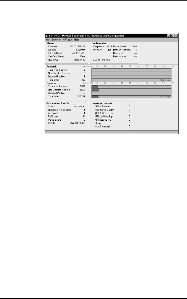
Windows NT/95 Utilities Setup
C 8 Spectrum24 Wireless LAN Adapter Product Reference Guide
C.7 Monitor Spectrum24 MU Mode
Figure 7-1: Monitor Spectrum24 Main Window (MU mode).
C.8 Using S24INFO
The S24INFO Monitor Spectrum24 MU window has four
menu bar items.
•Click File and select Exit to close S24INFO.
•Click Statistics to view additional tables on the main
window. Available tables include Transmit, Receive
and Miscellaneous.
•Click APTable. The APTable provides statistics about
individual Access Points (AP). The APTable appears
beside the Transmit and Receive table.
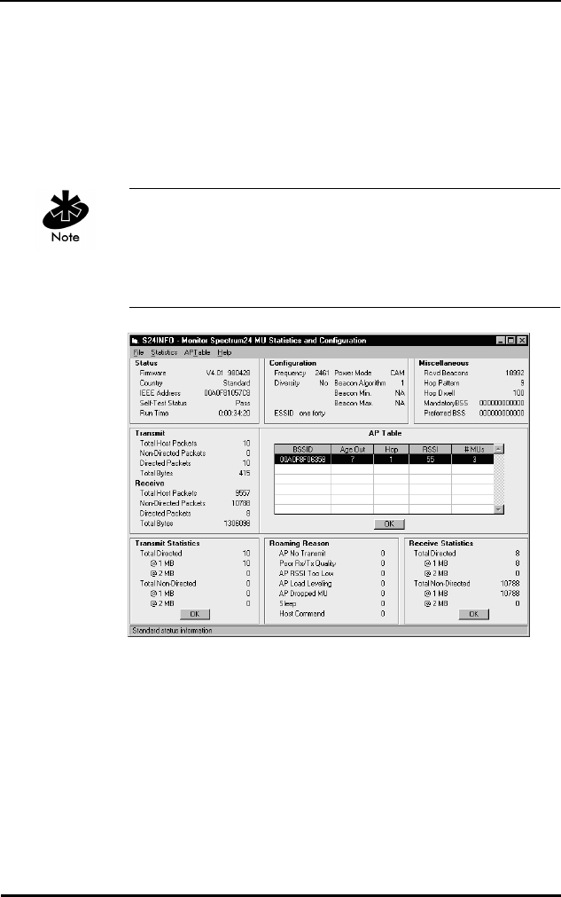
Windows NT/95 Utilities Setup
Spectrum24 Wireless LAN Adapter Product Reference Guide C 9
•The Help menu provides access to the Help contents
menu item and an About dialog that identifies the
S24INFO version plus Spectrum24 drivers recognized
in the system. Additional help appears when the cursor
passes over a component on the screen, by displaying
informative messages in the status bar.
S24INFO can run in either Monitor Spectrum24 MU mode
for a MobileUnit or Monitor Spectrum24 MAP for Micro
Access Point mode depending on the internal
configuration of the Spectrum24 adapter.
Figure 7-2: Monitor Spectrum24 Main Window with statistics.(MU
mode)
•Transmit Statistics replaces the Association Events table
located in the bottom left on the main window.
•Receive Statistics appears in the bottom right of the
window when activated.
•Miscellaneous locates in the upper right when
activated.

Windows NT/95 Utilities Setup
C 10 Spectrum24 Wireless LAN Adapter Product Reference Guide
•Click the associated OK button to close the Transmit
and Receive Statistics tables or select the checked
Transmit or Receive items from the Statistics menu to
close Transmit and Receive Statistics tables.
•Select the checked Miscellaneous line, from the
Statistics menu to close the Miscellaneous table. Refer
to Statistics and Configuration Screen descriptions In
MU Mode in this appendix for a detailed description
of these tables.
Tables Update twice per second. Graphs update once
per second.
C.9 Statistics and Configuration Screen
Descriptions In MU Mode
Status
Firmware adapter firmware version and date.
Country adapter country code. Standard
indicates the standard hop set.
This field displays Japan, Korea,
France, Spain, Israel or Belgium,
as appropriate.
IEEE Address indicates the Spectrum24 adapter
MAC address.
Self Test Status verifies that the Spectrum24 adapter
functions correctly.
Run Time elapsed time since adapter was
started. This counter rolls over at
approximately 36 hours.

Windows NT/95 Utilities Setup
Spectrum24 Wireless LAN Adapter Product Reference Guide C 11
Counters go from 0 to a maximum value, and wrap back
to zero.
Transmit
Total Host Packets the packet quantity transmitted by the
Spectrum24 adapter.
Non-Directed Packets broadcast packets transmitted to APs
without a specified recipient.
Directed Packets packets transmitted to a specified
recipient.
Total Bytes total bytes transmitted. The bar graph
reflects hundreds of bytes per second.
Receive
Total Host Packets the packet quantity received by the
Spectrum24 adapter.
Non-Directed Packetsbroadcast packets received by
the adapter.
Directed Packets packets received for a specified
address.
Total Bytes total bytes received. The bar graph
reflects hundreds of bytes per second.

Windows NT/95 Utilities Setup
C 12 Spectrum24 Wireless LAN Adapter Product Reference Guide
Counters go from 0 to a maximum value, and wrap back
to zero.
Association Events
Status indicates if the Spectrum24 adapter
is associated or unassociated with an
AP (out of range).
Number of
Associations
indicates how many times the
Spectrum24 adapter has established
or reestablished AP communication.
AP Count shows how many different APs the
Spectrum24 adapter has available
for association.
Full Scans the complete scans used to
determine communication quality.
Even when not accessed a full scan
occurs once each second.
Partial Scans the partial scans used to determine
communication quality.
AP ID the identifier assigned to the AP.
BSSID displays the Basic Service Set
IDentification number.
Configuration
Frequency displays the current Spectrum24
adapter frequency.
Diversity If a second antenna is enabled
diversity reads Yes. If not, diversity
reads No.

Windows NT/95 Utilities Setup
Spectrum24 Wireless LAN Adapter Product Reference Guide C 13
Net ID the AP network identifier. Net ID or
ESSID display depending on the
internal protocol used by the
Spectrum24 adapter.
ESSID the Extended Service Set Identifier
displays the proper ID as returned by
the Spectrum 24 adapter internal
protocol. ESSID display depends on
the internal protocol used by the
Spectrum24 adapter.
Power Mode indicates Power Save Polling (PSP).
Continuous Aware Mode (CAM)
indicates the adapter constantly
monitors activity.
Beacon Algorithm controls how often the mobile unit
awakes. Only valid when using PSP
Power Mode.
Beacon Minimum the minimum time lapse between
beacon wake ups when using
algorithm 11. The adapter uses
algorithm 12 in PSP mode. When not
using PSP Power mode with Beacon
Algorithm 11 or 12 NA displays.
Beacon Maximum the maximum time lapse between
beacon wake ups when using
algorithm 11. The adapter uses
algorithm 12 in PSP mode. When not
using PSP Power mode with Beacon
Algorithm 11 or 12 NA displays.

Windows NT/95 Utilities Setup
C 14 Spectrum24 Wireless LAN Adapter Product Reference Guide
Roaming Reason
AP No Transmit no AP transmissions received over a
specified time period.
Poor Rx/Tx Quality poor transmission quality. The
adapter uses internal diagnostics
to determine transmission quality.
It passes the rating to the S24INFO
utility.
AP RSSI Too Low the adapter Received Signal Strength
Indicator (RSSI) was weak.
AP Load Leveling the AP changed the MUs carried,
and balanced the MUs across
the network.
AP Dropped MU the AP quit serving the MU.
Power Mode Change the Mobile Unit has changed modes
(from PSP to CAM, or CAM to PSP)
and should reassociate.
Sleep the MU awakened and had to
reassociate.
Host Command the times a Host Command caused
a reassociation.

Windows NT/95 Utilities Setup
Spectrum24 Wireless LAN Adapter Product Reference Guide C 15
Counters go from 0 to a maximum value, and wrap back
to zero.
Transmit Statistics
Total Directed the information packets transmitted
to a specific recipient.
@1 MB shows transmission statistics for a
1 Mbps network.
@2 MB shows transmission statistics for a
2 Mbps network. If 2 Mbps is not
supported by or not enabled for
the adapter, NA displays in the
2 Mbps section.
Total Non-Directed the information packets transmitted
without a specified recipient.
@1 MB shows transmission statistics for a
1 Mbps network when no recipient
is specified.
@2 MB shows transmission statistics for a
2 Mbps network. If 2 Mbps is not
supported by or not enabled for
the adapter, NA displays in the
2 Mbps section.

Windows NT/95 Utilities Setup
C 16 Spectrum24 Wireless LAN Adapter Product Reference Guide
Counters go from 0 to a maximum value, and wrap back
to zero.
Receive Statistics
Total Directed the information packets sent expressly
to the adapter.
@1 MB the information packets sent expressly
to the adapter at a 1 Mbps rate.
@2 MB the information packets sent expressly
to the adapter at a 2 Mbps rate. If
2 Mbps is not supported by or is not
enabled for the adapter, NA displays
in the 2 Mbps section.
Total Non-Directed total information packets received
without a specified recipient.
@1 MB the information packets received by
the adapter at a 1 Mbps rate.
@2 MB the information packets received by
the adapter at a 2 Mbps rate. If
2 Mbps is not supported by or not
enabled for the adapter, NA displays
in the 2 Mbps section.

Windows NT/95 Utilities Setup
Spectrum24 Wireless LAN Adapter Product Reference Guide C 17
Hop Pattern, Hop Dwell, Mandatory BSS and Preferred BSS
display depending on the internal protocol used by the
Spectrum24 adapter. Counters go from 0 to a maximum
value, and wrap back to zero.
Miscellaneous
Rcvd Beacons AP beacons received by the
Spectrum24 adapter.
Hop Pattern specifies one of several frequency
sequences.
Hop Dwell specifies how long to stay on a given
frequency before switching to another
frequency.
Mandatory BSS specifies the only MAC AP address
where the MU can associate.
Preferred BSS the AP MAC address where the MU
prefers to associate. The MU
associates with another address when
it cannot locate the preferred address.

Windows NT/95 Utilities Setup
C 18 Spectrum24 Wireless LAN Adapter Product Reference Guide
The AP Table displays information about APs accessible to
the adapter. If the adapter associates with an AP in the AP
table, the appropriate adapter line highlights. Net ID and
AP ID display depending on the internal protocol used by
the Spectrum24 adapter.
AP Table
IEEE Address Or
BSSID
the AP MAC address.
Age Out sets to maximum value on signal
receipt. The adapter sends an
acknowledgment signal. If
verification does not return before the
value counts down to zero, the AP
deletes from the table.
Net ID the Network IDentification assigned
to the AP.
AP ID provides the AP IDentifier assigned to
the AP.
Hop the hop sequence the AP uses.
RSSI the Received Signal Strength
Indicator signal quality evaluation
comes from the adapter.
# MUs MUs associated with the AP.
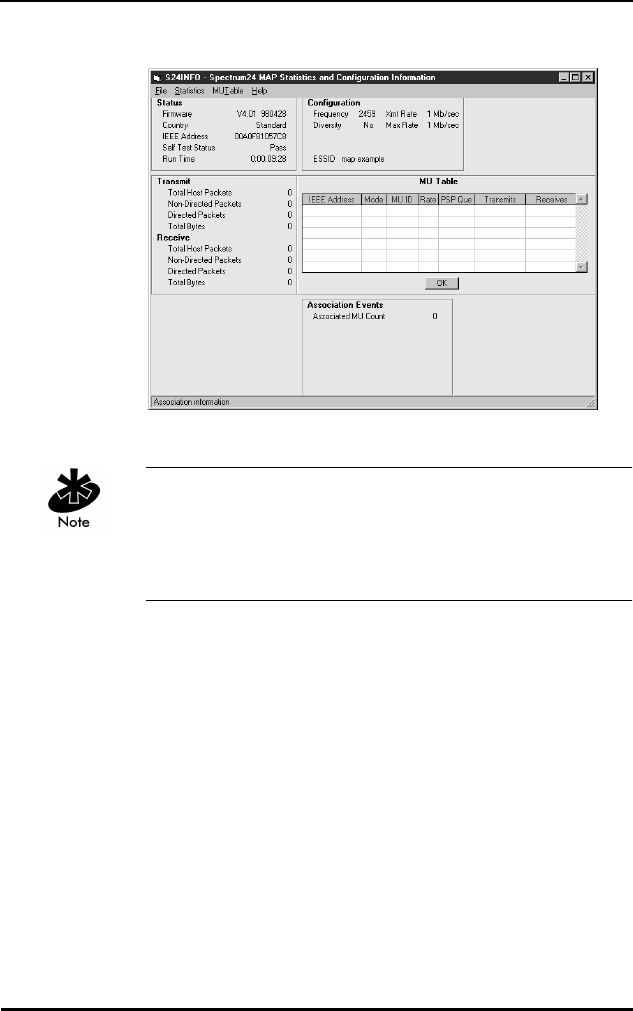
Windows NT/95 Utilities Setup
Spectrum24 Wireless LAN Adapter Product Reference Guide C 19
Figure 7-3: Monitor Spectrum24 Main Window (MAP mode).
S24INFO can run in either Monitor Spectrum24 MU mode
for a Mobile Unit or Monitor Spectrum24 MAP for Micro
Access Point mode depending on the internal
configuration of the Spectrum24 adapter.
The S24INFO Monitor Spectrum24 MAP window has four
menu bar items.
•Click File and select Exit to close S24INFO.
•Click Statistics to view additional tables. Available
tables include Transmit, Receive, and Miscellaneous.
•Click MU Table. The MU Table provides statistics
about individual Mobile Units (MU). The MU Table
appears beside the Transmit and Receive tables.
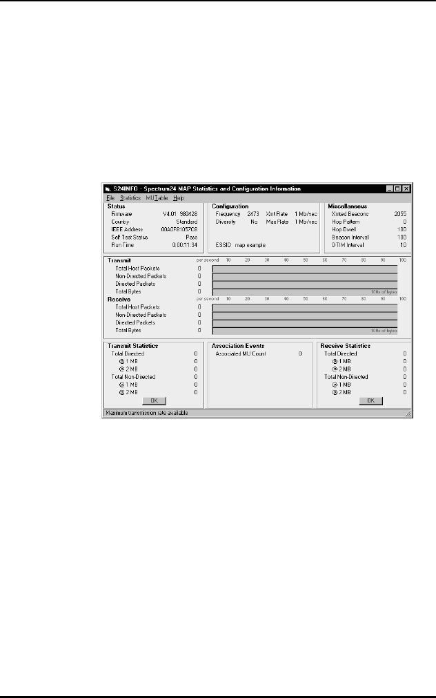
Windows NT/95 Utilities Setup
C 20 Spectrum24 Wireless LAN Adapter Product Reference Guide
•The Help menu provides access to the Help contents
menu item and an About dialog that identifies the
version of S24INFO plus Spectrum24 drivers
recognized in the system. Additional help appears
when the cursor passes over a component on the
screen, by displaying informative messages in the
status bar.
Figure 7-4: Monitor Spectrum24 Main Window with statistics
(MAP mode).
C.10 Statistics and Configuration Screen
Descriptions In MAP Mode
Status
Firmware adapter firmware version and date.
Country adapter country code. Standard indicates
the standard hop set. This field displays
Japan, Korea, France, Spain, Israel, or
Belgium, as appropriate.

Windows NT/95 Utilities Setup
Spectrum24 Wireless LAN Adapter Product Reference Guide C 21
IEEE Address indicates the Spectrum24 adapter MAC
address.
Self Test Status verifies that the Spectrum24 adapter is
functioning correctly.
Run Time elapsed time since adapter was started.
This counter rolls over at approximately
36 hours.
Transmit
Total Host
Packets
the packet quantity transmitted by the
Spectrum24 adapter.
Non-Directed
Packets
broadcast transmitted to APs without a
specified recipient.
Directed Packets packets transmitted to a specified
recipient.
Total Bytes total bytes transmitted. The bar graph
reflects hundreds of bytes per second.
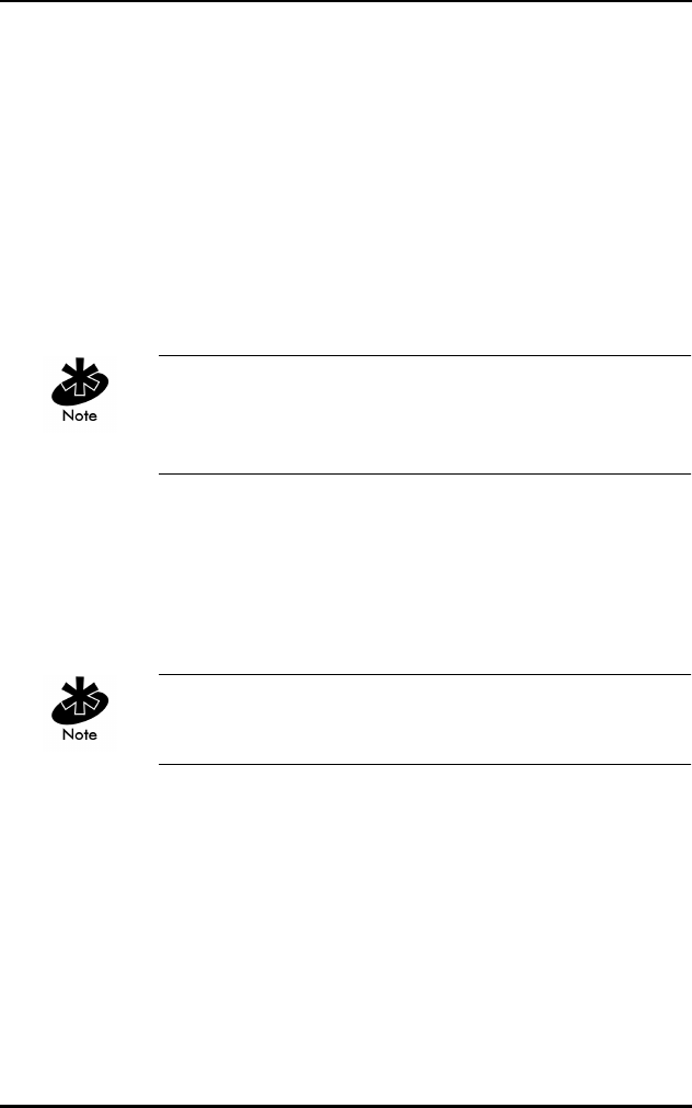
Windows NT/95 Utilities Setup
C 22 Spectrum24 Wireless LAN Adapter Product Reference Guide
Counters go from 0 to a maximum value, and wrap back
to zero. The associated bar graph shows activity over the
last second.
Counters go from 0 to a maximum value, and wrap back
to zero.
Receive
Total Host
Packets
the packet quantity received by the
Spectrum24 adapter.
Non-Directed
Packets
broadcast packets received by the
adapter.
Directed Packets packets received for a specified address.
Total Bytes total bytes received. The bar graph reflects
hundreds of byte per second.
Association Events
Associated MU Count the Mobile Units (MUs) associated
with this MAP.

Windows NT/95 Utilities Setup
Spectrum24 Wireless LAN Adapter Product Reference Guide C 23
Configuration
Frequency displays the current Spectrum24
adapter frequency.
Diversity If a second antenna is enabled
Diversity reads Yes. If not, Diversity
reads No.
Net ID the AP Network Identifier. Net ID and
ESSID display depending on the
internal protocol used by the
Spectrum24 adapter.
ESSID The Extended Service Set IDentifier
displays the proper ID as returned by
the Spectrum 24 adapter internal
protocol. ESSID displays depending
on the internal protocol used by the
Spectrum24 adapter.
Power Mode PSP indicates Power Save Polling.
Continuous Aware Mode (CAM)
indicates the adapter constantly
monitors activity.
Xmt Rate current transmission rate.
Max Rate maximum transmission rate
available.

Windows NT/95 Utilities Setup
C 24 Spectrum24 Wireless LAN Adapter Product Reference Guide
Counters go from 0 to a maximum value, and wrap back
to zero.
Transmit Statistics
Total Directed the information packets transmitted
to a specific recipient.
@1 MB shows transmission statistics for a
1 Mbps network.
@2 MB shows transmission statistics for a
2 Mbps network. If 2 Mbps is not
supported by or is not enabled for
the adapter, NA displays in the
2 Mbps section.
Total Non-Directed the information packets transmitted
without a specified recipient.
@1 MB shows transmission statistics for a
1 Mbps network when no recipient
is specified.
@2 MB shows transmission statistics for a
2 Mbps network. If 2 Mbps is not
supported by or is not enabled for
the adapter, NA displays in the
2 Mbps section.

Windows NT/95 Utilities Setup
Spectrum24 Wireless LAN Adapter Product Reference Guide C 25
Counters go from 0 to a maximum value, and wrap back
to zero.
Receive Statistics
Total Directed the information packets sent expressly
to the adapter.
@1 MB the information packets sent expressly
to the adapter at a 1 Mbps rate.
@2 MB the information packets sent expressly
to the adapter at a 2 Mbps rate. If
2 Mbps is not supported by or is not
enabled for the adapter, NA displays
in the 2 Mbps section.
Total Non-Directed total information packets received
without a specified recipient.
@1 MB the information packets received by
the adapter at a 1 Mbps rate.
@2 MB the information packets received
by the adapter at a 2 Mbps rate. If
2 Mbps is not supported by or is not
enabled for the adapter, NA displays
in the 2 Mbps section.

Windows NT/95 Utilities Setup
C 26 Spectrum24 Wireless LAN Adapter Product Reference Guide
Counters go from 0 to a maximum value, and wrap back
to zero. Hop Pattern, Hop Dwell, Beacon Interval, and
DTIM Interval display depending on the internal protocol
used by the Spectrum24 adapter.
Miscellaneous Statistics
Rcvd Beacons AP beacons received by the
Spectrum24 adapter.
Hop Pattern specifies one of several frequency
sequences.
Hop Dwell specifies how long to stay on a given
frequency before switching to another
frequency.
Beacon Interval the time between beacon packets.
DTIM the frequency of DTIM packets as a
multiple of beacon packets.
MU Table
IEEE Address the MU MAC address.
Mode the operating power mode of the
Mobile Unit.
PSP MU ID or
MU ID
the assigned identification number for
the Mobile Unit when in PSP mode.
PSP or PSP Que The transmit buffers pending Mbps. The
queue for this MU when in PSP mode.
Rate The transmit rate available for this MU.
Transmits The messages sent by the MU.
Receives The messages received by the MU.

Windows NT/95 Utilities Setup
Spectrum24 Wireless LAN Adapter Product Reference Guide C 27
MU Table displays information about MUs associated with
the adapter.
PSP MU ID, MU ID, PSP, PSP Que, and Rate display
depending on the internal protocol used by the
Spectrum24 adapter.
C.11 S24INFO Troubleshooting Hints
C.11.1 Symptom: Adapter not communicating
The Spectrum24 PCMCIA or ISA adapter does not
communicate. Check the following:
•Ensure the PCMCIA adapter seats firmly in the
PCMCIA slot.
•Ensure the ISA adapter seats firmly in the ISA slot.
•Verify the installation of the Spectrum24 Adapter
and Driver.
•Ensure the Spectrum24 Adapter is selected.
•Check the NET_ID or ESS_ID of the adapter to verify
the correct setting.
•If running TCP/IP protocol, use a valid IP Address.
•Verify TCP/IP protocol is bound to the adapter.
•In Windows 95, check device manager for IO Address
and IRQ conflicts.
•In Windows NT, select a different interrupt.
C.11.2 Symptom: Adapter associated but not
communicating
The Spectrum24 adapter attaches to the AP, but does not
communicate. Check the following:

Windows NT/95 Utilities Setup
C 28 Spectrum24 Wireless LAN Adapter Product Reference Guide
•In Windows 95, check device manager for IO Address
and IRQ conflicts.
•In Windows NT, select a different interrupt.
C.11.3 Symptom: Out of Memory Error
S24INFO or S24UTIL do not run or produce Out of
Memory Errors. Verify the following:
•Ensure the Transport is installed and bound to the
Spectrum24 adapter.
C.12 Using S24UTIL
S24UTIL allows the user to get information from the
Spectrum24 adapter, and temporarily change some
settings in the Spectrum24 Driver.
S24UTIL main menu contains two items.
•Click File and select Exit to close S24UTIL or click Exit.
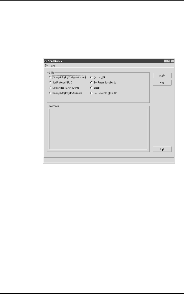
Windows NT/95 Utilities Setup
Spectrum24 Wireless LAN Adapter Product Reference Guide C 29
•The Help menu provides access to the Help contents
and About dialog that identifies the version of S24UTIL
plus Spectrum24 Drivers recognized in the system.
Additional help appears when the cursor passes over
a component on the screen by displaying informative
messages in the status bar.
Figure 7-5: S24UTIL Main Window
•The S24UTIL window consists of two frames.
•The top frame contains option buttons. Select the
appropriate button for the desired utility.
•Clicking Apply executes the utility selected and
displays relevant information in the Feedback frame.

Windows NT/95 Utilities Setup
C 30 Spectrum24 Wireless LAN Adapter Product Reference Guide
C.13 Utility Frame
The Display Adapter Configuration Info option button
displays basic configuration information about the
Spectrum24 WLAN Adapter. The table below lists the
information displayed after clicking the Apply button.
Adapter Association indicates if the adapter is associated
or not associated.
IRQ shows the IRQ used by the adapter.
I/O Address displays the Spectrum24 I/O
address.
Memory Address displays the Spectrum24 adapter
base memory address.
Net ID the hexadecimal address of the
network where the adapter
associated. The decimal value
appears in parenthesis. This
parameter displays only if the
Spectrum24 adapter is using the
Spring Protocol.
ESSID the Extended Service Set Identifier.
This parameter displays only if the
Spectrum24 adapter is using the
802.11 protocol. The symbols > and
< delimit the ESSID.
Firmware displays the version and date of the
Spectrum24 adapter firmware.
Driver Version displays the version of the
Spectrum24 adapter driver installed
in the system.

Windows NT/95 Utilities Setup
Spectrum24 Wireless LAN Adapter Product Reference Guide C 31
Click the Set Preferred AP_ID (Spring Protocol) Option
button to set the Preferred AP_ID for the adapter. When
selected a Roaming Type radio button group appears
under the Help button.
Click the Set Preferred BSSID (802.11 Protocol) option
button to set the adapter Preferred BSSID. When selected,
a Preferred BSSID dialog box and Mandatory BSSID dialog
box appear under the Help button.
Country Code adapter country code. Standard
indicates the standard hop set.
This field displays Japan, Korea,
France, Spain, Israel or Belgium
as appropriate.
IEEE Address indicates the Spectrum24 adapter
IEEE MAC address.
Roaming Types
Normal the Feedback frame acknowledges
the roaming setting.
Preferred asks for the hexadecimal ID of the
desired AP association. See a
network administrator for information
about AP ID.
Exclusive asks for the hexadecimal ID of the
desired AP association. Association
limits to the specified AP. See the
network administrator for information
about AP ID.

Windows NT/95 Utilities Setup
C 32 Spectrum24 Wireless LAN Adapter Product Reference Guide
Enter the IEEE MAC address for the Preferred and
Mandatory Access Points. Entering zeros tells the
Spectrum24 Adapter it is OK to associate with any
Access Point.
The Display Net_ID/AP_ID Info (Spring Protocol) option
button displays information about AP association status
and Net_ID. The following information displays for
Net_ID/AP_ID Info:
The Display ESSID/BSSID Info (802.11 Protocol) option
button displays information about AP association status
and ESSID. The following information displays for ESSID/
BSSID Info:
Adapter Association indicates if the adapter is associated
or not associated.
Net ID the hexadecimal address of the
network where the adapter
associated. The decimal address
displays in parenthesis.
AP ID the hexadecimal address of the AP
where the adapter associated. The
decimal address displays in
parenthesis.
Preferred AP ID the desired AP ID if set, otherwise 0.
AP IEEE Address indicates the AP IEEE MAC address.
ESSID The Extended Server Set IDentifier (up
to 32 characters).
BSSID the IEEE MAC address of the AP
where the adapter is associated.
Preferred BSSID the desired BSSID if set, otherwise 00
00 00 00 00 00.

Windows NT/95 Utilities Setup
Spectrum24 Wireless LAN Adapter Product Reference Guide C 33
The Display Adapter Info/Statistics displays statistical
information kept by the adapter. Click Apply to display the
following information:
Mandatory BSSID the mandatory BSSID if set, otherwise
00 00 00 00 00 00.
Adapter Association indicates if the adapter is associated
or not associated.
Power Mode designates whether Spectrum24
is operating in CAM (Continuous
Aware Mode) or PSP (Power Saving
Poll) mode.
Beacon Algorithm the PSP mode Beacon Algorithm
determines how often the adapter
wakes up to check for data. Setting
this to 1 wakes more often. Setting
this to 10 wakes less often.
Transmitter Status (Tx) the transmitter is either Enabled
or Disabled.
Net ID the hexadecimal address of the
network where the adapter
associated. The decimal address
displays in parenthesis. This
parameter displays only when using
Spring Protocol.
AP ID the hexadecimal address of the AP
where the adapter associated. The
decimal address displays in
parenthesis. This parameter displays
only when using Spring Protocol.

Windows NT/95 Utilities Setup
C 34 Spectrum24 Wireless LAN Adapter Product Reference Guide
Click the Set Net_ID (Spring Protocol) option button to
enter a new Net_ID for the Spectrum24 adapter in the
dialog box provided. Valid Net_IDs range from 0 to 255
decimal (0 to FF hex). Click Apply to set the Net_ID. The
feedback should be as follows:
ESSID the Extended Service Set Identifier.
Up to 32 characters. This parameter
displays only when using 802.11
protocol.
BSSID the IEEE MAC address of the AP
where the adapter is associated. This
parameter displays only when using
802.11 protocol.
Association ID displays the AP ID where the
Spectrum24 adapter associated.
Radio shows the radio version the
Spectrum24 adapter uses. Version 1
notes as X, version 2 through 4 note
as A.
AP Count the APs listed in the Spectrum24
AP table.
Full Scans full scans performed by the
Spectrum24 adapter.
Partial Scans partial scans performed by the
Spectrum24 adapter.
Request Accepted verifies the computer received the
new ID.
The Net ID has been
set to xxx (xxx).
states the present Net ID setting.

Windows NT/95 Utilities Setup
Spectrum24 Wireless LAN Adapter Product Reference Guide C 35
Click the Set ESSID (802.11 Protocol) option button to
enter a New ESSID for the Spectrum24 adapter in the
dialog box provided. Valid ESSIDs can be any character,
and can be up to 32 characters long. Click Apply to set the
ESSID. The feedback should be as follows:
Click the Set Power Save Mode option button to change
the adapter power parameters. A Power Mode option
button group appears below the Help button. Select the
appropriate power mode parameter. Allows entering the
Beacon Algorithm, Min and Max values for PSP timers in
the dialog boxs provided.
Request Accepted verifies the computer received the
new ID.
The ESSID has been
set to >xxx<.
states the present ESSID setting.
PSP Power Save Polling mode-This setting
allows the adapter to sleep between
checking for network activity. A
sleeping adapter saves power. Also
allows entering the Beacon
Algorithm, Min and Max values for
PSP timers.
CAM Continuous Aware Mode-This setting
tells the adapter to continually check
for network activity. This mode uses
the most power.

Windows NT/95 Utilities Setup
C 36 Spectrum24 Wireless LAN Adapter Product Reference Guide
Symbol Technologies recommends PSP mode for battery
powered devices. PSP Mode coupled with Beacon
Algorithm 11, Min 1, Max 10 are good power saving
parameter settings.
Click Apply, the feedback frame displays:
Request accepted.
The following change is now in effect:
Power Save Mode: Continuously Aware Mode
or
Power Save Mode: Power Saving Polling Mode
Beacon Algorithm: 11
Beacon Minimum: 1
Beacon Maximum: 10
The Sleep option button puts the adapter in to sleep mode.
Resume awakens the adapter. Click Apply to set the
adapter sleep state.
The Set Device to MicroAP / MU radio button sets the
Spectrum24 adapter into either MicroAP mode where it
acts as a Micro Access Point, or into MU mode where it
acts as a Mobile Unit. The Net ID or ESSID can be altered
prior to clicking the Apply button.

Spectrum24 Wireless LAN Adapter Product Reference Guide D 1
Appendix D Spectrum24 DOS
Keywords
Keywords For
Power Saving Mode
Description
Beacon_Alg selects the beacon algorithm (1-12)
for every nth beacon. Beacons
broadcast every 100 ms, 1 selects 10
polls per second. Selecting 1
provides the best performance while
10 provides the highest power
saving. Selecting 11 selects a
dynamic algorithm that varies from
the Beacon_Maximum to the
Beacon_Minimum. Algorithm 11 uses
Beacon_Minimum with network traffic
for the unit and extends to
Beacon_Maximum without traffic.
Selecting 12 selects an algorithm
where the WLAN adapter switches
from PSP-11 to CAM automatically
depending on data traffic (PSP only).
Also recognizes Beacon_Algorithm
for backward compatibility.
Beacon_Minimum programs the minimum beacon
interval for the dynamic algorithms.
Default is 1. (PSP, Algorithm
11/12 only)
Beacon_Maximum programs the maximum beacon
interval for the dynamic algorithms.
Default is 10. (PSP, Algorithm
11/12 only)

Spectrum24 DOS Keywords
D 2 Spectrum24 Wireless LAN Adapter Product Reference Guide
Powermgmt sets power management option. The
default is 'No' for CAM. 'Yes' sets the
card to PSP mode.
Keywords For
MicroAP Mode
Only
Description
MicroAP enables Micro AP operation when
set to ‘Yes’. If enabled, the
PowerMgmt keyword is ignored and
the meaning of the Tx_Rate and
Ess_ID keywords change.
MicroAP_Hop_Set specifies the Hop Set used by the
Micro AP.
MicroAP_Hop_Seq specifies the Hop Sequence used by
the Micro AP.
MicroAP_BDelay specifies the delay for broadcast
packets being transmitted from
the MAP.
Base_Rate (MAP Only) set to 1 or 2 to require
associating MUs to operate at 1
Mbps or 2 Mbps. This keyword can
be used multiple time to require
multiple data rates. If the MU is not
capable of the required data rate(s),
it cannot associate with this MAP.
Keywords For
Power Saving Mode
Description

Spectrum24 DOS Keywords
Spectrum24 Wireless LAN Adapter Product Reference Guide D 3
Keywords for
CSS and Plug
and Play Clients
Description
Cardservices enables card services installation if no
parameter is present or if the parameter
is Yes. Requires I/O mode ‘No’
disables. Plug and Play keyword cannot
be present or set to No.
Socketservices enables socket services installation if no
parameter or if the parameter is ‘Yes’
(requires I/O mode). 'No' disables PNP
keyword cannot be present or set
to ‘No’.
PNP sets the driver to require the presence of
slainit.exe. Default is ‘No’ if slainit.exe
is not loaded, preventing the driver
from loading. This keyword forces
Mode to IO and ignores the Interrupt,
IOAddress and Memory keywords.
Keywords In
MicroAP Or
MU Mode
Description
Interrupt designates the port hardware interrupt
(3 to 15). Default is 5. In protocol.ini
the keyword Int is supported.
IOAddress I/O address (0x240 to 0x380) for
the adapter. Default is 0x300. Also
recognizes IOADDRESS for backward
compatibility. This is a hex number.

Spectrum24 DOS Keywords
D 4 Spectrum24 Wireless LAN Adapter Product Reference Guide
Memory resource memory location (0xC000 to
0xE800). Default is 0xD000. Memory
mode uses the 32Kb block; I/O Mode
uses the 4Kb block. Verify the
designated memory block is reserved
using an extended memory manager
(e.g. EMM386.EXE with the 'x= option
for DOS). In protocol.ini, the keyword
Mem is also supported. This is a
hex number.
Tx_Rate set to 1 or 2 to enable operation at
1 Mbps or 2 Mbps. Use this keyword
multiple time to enable multiple data
rates. If the Adapter is not capable of
the requested data rate, the entry is
ignored. If this keyword is not entered,
the Adapter operates at all data rates it
can. If the Adapter is setup to be a MAP,
this entry means that the associating
MUs can optionally use this data rate.
Mode Add Mode to the file to set I/O mode. If
Mode is not in file, the PCMCIA
interface is set to memory mode
(default). I/O mode requires 16 bytes of
I/O space, 4Kb of attribute memory.
Memory mode requires 16 bytes of I/O
space, 32Kb of memory (4Kb attribute
or 32Kb common memory). In memory
mode the attribute and common
memory start at the same segment
address. Only 8-bit I/O is supported.
Keywords In
MicroAP Or
MU Mode
Description

Spectrum24 DOS Keywords
Spectrum24 Wireless LAN Adapter Product Reference Guide D 5
ESS_ID sets the ESS_ID. Default is "101". The
ESS_ID is a 32-character, case sensitive
string. In net.cfg, quotes are not
required unless spaces are needed in
the ESS_ID. In protocol.ini quotes are
required. Symbol recommends using
quotes.
The ESS_ID string "BRDCST" is reserved
and places the Adapter into the
broadcast ESS_ID mode. In this mode
the Adapter adopts the ESS_ID of the
first AP that it finds, and continues to
roam with that ESS_ID until rebooted.
If in the MAP mode, this value is used as
the ESS_ID of the MAP. Symbol supports
the following alternate keywords for
backward compatibility: DOMAIN,
RF_NETWORK_ID, NET_ID.
PCMCIA_IO sets alternate PCMCIA controller I/O
address. The default is 3E0. Other
possibilities are 3000 and FCFC.
This is a hex number.
Unittype for ISA adapter, set to 2000. Not
applicable for PC Card or the ISA
Plug and Play adapter.
Keywords In
MicroAP Or
MU Mode
Description

Spectrum24 DOS Keywords
D 6 Spectrum24 Wireless LAN Adapter Product Reference Guide
Neither file is case sensitive. Use of case is by preference.
The only exception is the ESS_ID argument, which is
case sensitive.
Keyword Format In
PROTOCOL.INI
Description
KEYWORD=YES in protocol.ini all arguments to a
keyword require an '=' between the
keyword and the argument.
KEYWORD=0x3E0 in protocol.ini prefix all hex numbers
with an ‘0x’.
Keyword Format In
NET.CF
Description
KEYWORD YES in net.cfg only a space is required.
KEYWORD 3E0 in net.cfg this is not required,
but a hex number has to be used
where expected and a decimal point
used elsewhere.

Spectrum24 Wireless LAN Adapter Product Reference Guide E 1
Appendix E Spectrum24 DOS Utilities
The flash utility programs included on the diskette are
compatible with PCs using an Intel/Cirrus (PCIC)
compatible PCMCIA interface. S_WFA, S_INFO and do
not require a specific PCMCIA interface.
For information on the 32-bit Windows utilities, refer to
32-Bit Spectrum24 Utilities in Appendix C. Load Slainit.exe
before running utilities. ISA Plug and Play adapter requires
Slainit.exe loaded to function.
E.1 S_WFA
This utility functions in MU mode only. In some situations,
the S_WFA utility provides a short waiting period after
running the driver and before attaching to the network.
The utility waits for the MU to associate with an AP
before continuing.
At the DOS prompt, enter:
s_wfa
The system displays:
S_WFA Version 4.xx
SLAAPI found at 096E
Waiting for MU Association
Type any key to abort..
Firmware: V4.xx Date: xxxxxx
Country: Standard
ESS_ID: S24NET
MAC Adrs: 00 A0 F8 21 56 3D
Searching. Adapter is associated:
Mode: CAM
Scans: 0
AP IEEE: 00 A0 F8 3D 21 56

Spectrum24 DOS Utilities
E 2 Spectrum24 Wireless LAN Adapter Product Reference Guide
E.2 S_UTIL
S_UTIL is a DOS-utility program that can configure the
adapter and obtain statistics. S_UTIL runs only after the
driver has been installed.
The program provides a list of available commands in the
absence of a command line parameter. Each command
requires a one-letter code to display current configuration
parameters or statistics. Some commands allow optional
parameters to change driver/firmware settings only for the
current session.
At the DOS prompt, enter:
s_util <func> [parms]:
where func and parms:
Adisplays LAN adapter configuration
including interrupt, I/O address,
memory address, ESS_ID, firmware
version, IEEE table number (country
code) and IEEE MAC address.
Bdisplays the BSS_IDs of the
associated AP, preferred AP and
mandatory AP.
B [hh hh hh hh hh hh] sets the preferred AP BSS_ID for the
adapter to associate. The BSS_ID
represents the AP MAC address.
Csets the unit to CAM. The P
parameter sets it to PSP. (MU
mode only).
E <ESS_ID String> sets the 32-character ESS_ID for
the adapter.

Spectrum24 DOS Utilities
Spectrum24 Wireless LAN Adapter Product Reference Guide E 3
I <all> displays association status, power
mode, beacon algorithm and
transmit status. This also displays
the ESS_ID, station ID and radio
type. The last line shows the APs
in the AP table and the number
of scans. The all option displays
additional transmit and receive
statistics. S_INFO also provides
this information.
J [hh hh hh hh hh hh] sets the mandatory AP BSS_ID
for the adapter to associate.
The BSS_ID represents the AP
MAC address.
L <value> get/set options that apply only to
Symbol radio terminals. The value
40 selects no power down in
Symbol terminals, and the value 20
automatically powers down the
terminals in a cradle.
O <option> sets the firmware option for
the adapter.
Psets the unit to PSP mode. The C
parameter sets it to CAM. (MU
mode only)
T <u> [v] [w] get/set beacon parameters. The u
parameter indicates the algorithm.
The v parameter indicates the
minimum beacon interval. The w
parameter indicates the maximum
beacon interval. (MU mode only)

Spectrum24 DOS Utilities
E 4 Spectrum24 Wireless LAN Adapter Product Reference Guide
E.3 Examples
With no parameters, S_UTIL displays:
Spectrum24 API Utility V1.06a
Usage: S_UTIL <function code> [<optional parameters>,,,]
Function codes and [optional] parameters:
A - Display Adapter Configuration info
B - Display ESS_ID/BSS_ID info
B <BSS_ID> - Set Preferred BSS_ID. B X to clear
C - Set Continuous Power Mode (CAM)
E <ESS_ID String> - Set ESS_ID
I - Display Adapter Info/Statistics
J <BSS_ID> - Set Mandatory BSS_ID. J X to clear
L - Get/Set SYMBOL_OPTIONS (L <value> to set)
O <option> - Set Firmware Option
P - Set Power Save Mode (PSP)
T - Display Beacon/PSP Parameters
T [<Algorithm> [<min> [<max>]]] - Set Beacon parameters
The following apply to the MicroAP -
W - Display Access Control List (ACL)
X <IEEE address> - Add ACL Entry
Y <IEEE address> - Delete ACL Entry
Z - Clear ACL
For example, to view current adapter parameters from the
DOS prompt, enter:
s_util A
Used In MicroAP Only
Wdisplays the MicroAP ACL.
X<hh hh hh hh hh hh> adds a MAC address to the ACL.
The ACL allows a maximum of
16 entries. Duplicate ACL entries
are not detected.
Y<hh hh hh hh hh hh> removes a MAC address from
the ACL.
Zclears the ACL of all entries.

Spectrum24 DOS Utilities
Spectrum24 Wireless LAN Adapter Product Reference Guide E 5
To set the ESS_ID to Department 1, from the DOS
prompt, enter:
s_util E “Department 1”
To set the beacon algorithm to 11 with a minimum of 2
and a maximum of 10, from the DOS prompt, enter:
s_util T 11 2 10
The '2' and the '10' are optional.
To change the power mode to PSP, from the DOS prompt,
enter:
s_util P
E.4 S_INFO
S_INFO provides a dynamic, full screen display of selected
firmware statistics and configuration variables. It obtains
the data through the driver extension get_adapterinfo and
get_statistics functions, and it periodically refreshes the
display with updated information. This utility can identify if
the MU communicates properly.
At the DOS prompt, enter:
s_info

Spectrum24 DOS Utilities
E 6 Spectrum24 Wireless LAN Adapter Product Reference Guide
In MicroAP mode, the system displays:
***********SPECTRUM24 ADAPTER STATISTICS - MAP ********** V4.25 09/16/98 ***
Address 00A0F8-161CA8| Fw Ver V4.28 | Tx Rate 1 Mb/Sec | Freq 2461
Country STD | Selftest PASS | Max Rate 1 Mb/Sec | Ass'd MUs 1
SSID s24net | Diversity OFF | Hop Pattern 0 | Bcn Interval 100
RunTime 00:00:00:00 | | Hop Dwell 100 | DTIM Interval 5
********** TX Statistics ************************* RX Statistics *************
Tx Host 1 B/Sec 0 | Rx Host 2 B/Sec 0
Tx NDir 3 Tx Bcn 960 | Rx NDir 0
Tx Dir 0 | Rx Dir 2
****************************** Associated MUs ******************************* #
Mode Adrs ID Rat Fifo TxDir RxDir
1 CAM 10461C 1 1 0 0 3
2 CAM 105623 2 2 0 0 2
3
4
5
6
7
8
9
10
11
12
F10|q = exit program

Spectrum24 DOS Utilities
Spectrum24 Wireless LAN Adapter Product Reference Guide E 7
In MU Mode, the system displays:
*********** SPECTRUM24 ADAPTER STATISTICS - MU ********** V4.25 09/16/98 ***
Address 00A0F8-161CA8| Fw Ver V4.28 | Tx Rate 1 Mb/Sec | Freq 2421
Country STD | Selftest PASS | Max Rate 1 Mb/Sec | Status ASSOC'D
SSID s24net| Diversity OFF | Hop Pattern 27 | Station ID 1
RunTime 00:00:00:54 | | Hop Dwell 100 | Power Mode CAM
*********** TX Statistics ************************* RX Statistics************ Tx
Host 163 B/Sec 0 | Rx Host 168 B/Sec 0
Tx NDir 2 | Rx NDir 12 Rx Bcn 517
Tx Dir 161 | Rx Dir 162
********************************* AP Table *********************************** #
St AG BSSID RS #MU Hp | # St AG BSSID RS #MU Hp
1*CE 0F 73DA7F 65 1 27 |11
2 |12
3 |13
4 |14
5 |15
6 |16
7 |17
8 |18
9 |19
10 |20
F10|q = exit program
To return to DOS, press ESC or ENTER.
The display includes configuration and status information,
transmit statistics, receive statistics, roaming statistics,
optional additional statistics and the known AP table.
E.5 Configuration/Status
S_INFO displays the standard information about the
MicroAP or MU. A brief description of the display
content follows.

Spectrum24 DOS Utilities
E 8 Spectrum24 Wireless LAN Adapter Product Reference Guide
Address device MAC address.
Country the adapter country code. STD
indicates the standard hop set for the
adapter. In certain countries, this
field displays Japan, Korea, France,
Spain, Mexico, Belgium or Israel, as
appropriate.
SS ID the ESS_ID.
Runtime the elapsed time since the adapter
initialized.
Fw Ver the adapter firmware version
and date.
Selftest indicates adapter self-tests. A
resulting PASS indicates no problem
no problems were found. The
positional bits below indicate each
failed test.
Bit (hex) Corresponding test.
001 code checksum
002 received first-in-first-out (Rx
FIFO)
004 transmitted first-in-first-out
(Tx FIFO)
008 received direct memory
access (Rx DMA)
010 transmitted direct memory
access (Tx DMA)
020 radio configuration
040 radio loopback
080 real-time clock
100 CPU clock

Spectrum24 DOS Utilities
Spectrum24 Wireless LAN Adapter Product Reference Guide E 9
200 host interface
400 radio interface
800 random access memory
(RAM)
Diversity indicates YES for diversity enabled or
NO for single antenna selected.
Tx Rate displays the transmission data rate
used by the adapter in Mbps.
Max Rate displays the maximum transmit rate
available for use by the adapter
in Mbps.
Hop Pattern each hop set has a selection of hop
patterns available. The field displays
the hop pattern used by the AP that
associates with the MU.
Hop Dwell displays the time between hops in
K-µs units.
Freq displays the current communication
frequency for the adapter.
Status
(MU mode only)
displays the status for the MU.
Station ID
(MU mode only)
indicates the station ID number
assigned to the MU during its
last association.
Power Mode
(MU mode only)
displays CAM or PSP
Ass'd MUs
(MicroAP mode only)
displays the total associated MUs.
Bcn Interval
(MicroAP mode only)
displays the time between beacon
packets in 100 K-µs units.

Spectrum24 DOS Utilities
E 10 Spectrum24 Wireless LAN Adapter Product Reference Guide
E.5.1 Transmit Statistics
Transmit statistics indicate activity over the last second. This
display is useful if background operations such as pings
occur. Locate counters on the left side of the display.
E.5.1.1 Receive Statistics
Receive statistics indicate activity over the last second. This
display is useful if background operations such as Pings
occur. Locate counters on the right side of the display.
DTIM Interval
(MicroAP mode only)
displays the frequency of DTIM
packets as a multiple of beacon
packets. This indicates how many
beacons equal one DTIM cycle.
Tx Host the packets passed to the driver.
An interrupt conflict in the driver
installation can occur when these
fields equal 0 (zero).
Tx NDir the Nondirected packets transmitted.
Tx Dir the Directed packets transmitted.
B/Sec approximates the bytes per
second sent.
Tx Bcn
(MicroAP mode only)
the total beacons transmitted.
Rx Host the packets passed from the driver.
If these fields equal 0 (zero), an
interrupt conflict in the driver
installation can occur.
Rx NDir the Nondirected packets received.
Rx Dir the Directed packets received.
B/Sec approximates the bytes per second
received.

Spectrum24 DOS Utilities
Spectrum24 Wireless LAN Adapter Product Reference Guide E 11
E.5.2 AP Table (MU Mode only)
The lower section is the AP table. The AP table contains the
AP status, BSS_ID, hop sequence, RSSI and MU load
information for all known APs.
Press PgUp and PgDn to display the second block of APs.
E.5.3 Associated MU Table (MicroAP Mode only)
The lower section is the associated MU table. The table
contains the MU status, the ID assigned by the MicroAP,
and transmit and receive statistics.
Rx Bcn
(MU mode only)
the total beacons received.
St the status byte. Sign bit indicates MU association
with the AP.
AG the AP table entry age-out counter. An age-out
counter of 0 through 8 maintains each AP table
entry. Value 8 indicates an AP acknowledgment
of an MU scan. A decreased value indicates
non-acknowledgment. The MU removes an AP
entry from the table when the age-out counter
value decrements to 0.
BSS_ID the last 3 hexadecimal fields of the AP MAC
address.
RS the AP RSSI value as measured by the MU.
#MU the MUs associated with the AP. The load
information helps the MU determine when to
roam. The number is always 0 (zero) if the MU
associates with a MicroAP.
Hp the hop sequence used by the AP.
Mode displays the MU power-operating mode.
Adrs the MU MAC address.

Spectrum24 DOS Utilities
E 12 Spectrum24 Wireless LAN Adapter Product Reference Guide
Press PgUp and PgDn to display the second block of MUs.
E.5.4 Transmit And Receive Statistics Table
The transmit and receive statistics and graphs indicate
activity over the last second. Use this display if background
operations such as Pings occur. Counters locate on the left
side of the display. The horizontal bar graph shows activity
over the last second.
E.6 S_VER
S_VER displays the version/date of the installed firmware. It
also displays the Diversity mode status.
At the DOS prompt, enter:
s_ver
ID the station ID assigned by the AP at association.
Rat displays the current transmit rate available for
the MU in Mbps.
FIFO the transmits buffers pending for this MU.
TxDir the fragments transmitted to this MU.
RxDir the fragments received to this MU.
Tx_Host and
Rx_Host
the packets passed to and from the driver.
If these fields register 0 (zero), an interrupt
conflict in the driver installation can exist.
NDir_U and
Dir_U
the Nondirected and Directed packets.
Byte/sec approximates the bytes per second sent
and received.

Spectrum24 DOS Utilities
Spectrum24 Wireless LAN Adapter Product Reference Guide E 13
The system displays:
Spectrum24 LAN Adapter Version Display Utility, V4.xx
(C) Copyright 1996 Symbol Technologies, All Rights Reserved.
Card in slot 1
FIRMWARE: IEEE Addr: hh hh hh hh hh hh
Ver: V4.xx
Date: xxxxxx
Country: United States (1)
Diversity: ON
If using s_ver to display the CIS parameters, at the DOS
prompt, enter:
s_ver -x
The system displays:
Spectrum24 LAN Adapter Version Display Utility, V4.xx
(C) Copyright 1996 Symbol Technologies, All Rights Reserved.
Card in slot 1
FIRMWARE: IEEE Addr: hh hh hh hh hh hh
Ver: V4.xx
Date: xxxxxx
Country: United States (1)
Diversity: ON
CIS: Ver: Vx.xx
Serial: 00032123
Mfg Date: 00080896
Dest Code: FW: USA
Mfg Info: TSW:none
Power: 500
CkSum: CAE3
E.7 S_UPDATE
S_UPDATE updates the flash image with a new firmware
file. The standard firmware file is SLA_FW.BIN. This
program does not change the IEEE address or the country
code. Locate S_UPDATE and the latest firmware file
in the FIRMWARE directory on the Installation and
Utilities diskette.

Spectrum24 DOS Utilities
E 14 Spectrum24 Wireless LAN Adapter Product Reference Guide
Do not run S_UPDATE after driver installation. Uninstall
and reinstall the driver. The ISA Plug and Play WLAN card
requires users to load SLAINIT.EXE prior to loading the
driver or updating the firmware.
S_UPDATE requires an Intel compatible PCMCIA controller
(Intel, Vadem, Cirrus or Ricoh), or card and socket services
and SLAINIT. If using EMM386, reserve the memory
location at D000-D0FF (X=D000-D0FF).
To update the adapter firmware:
At the DOS prompt, enter:
s_update
The system displays:
Spectrum24 LAN Adapter FLASH Update Utility, Vx.xx
Reading the firmware binary file (SLA_FW.BIN)...
Press any key to continue, CTRL-C to abort
Press any key. The system displays:
FIRMWARE: IEEE Addr: 00 A0 F8 00 04 D2
Ver: 'V2.00'
Date: '960320'
(AMD) Erasing flash... Operation successful
Programming Flash... ................................
When the program completes, it displays:
Programming operation successful
Update Operation completed
To display other program options for S_UPDATE, enter:
s_update -?

Spectrum24 Wireless LAN Adapter Product Reference Guide F 1
Appendix F WLAN Adapter
Specifications
PC Card
Physical
Dimensions
(less antenna)
3.3 inches x 2.1 in. x 0.2inches (85 mm x
54 mm x 5 mm)
Weight
(with antenna)
1.6 oz (45.36 g)
Operating
temperature 32 to 130 °F (0 to 54 °C)
Humidity 95% 95% maximum non condensing
Cargo/Packaged 6ft(1.8m) drop 5hz vibration Mil-Std 810E
Altitude 15,000 ft. (4.6 km) - Storage 8,000 ft.
(2.4 km)- Operating
Vibration 2 G peak, sine; 0.02 G peak random
(5Hz - 2000Hz)
Shock 40 G, 11mS, half sine
ESD meets CE-Mark
PCMCIA
Compliance
Type II, Version x.xx, Card and Socket
services x.xx
ISA Adapter Physical
Dimensions 6.2 in. x 4.2 in. (16 cm x 11 cm)
Weight 4.3 oz. (122 g)
Operating
Temperature 32 to 100 °F (0 to 40 °C)
Storage
Temperature -15 to 140 °F (-40 to 60 °C)

WLAN Adapter Specifications
F 2 Spectrum24 Wireless LAN Adapter Product Reference Guide
Humidity 95% max. non-condensing
Cargo/Packaged 6 ft. drop; 5 Hz vibration Mil-Std 810E
Altitude 15,000 ft. - Storage, 8,000 ft. -
Operating
Vibration 2 G peak, sine; 0.02 G peak random
(5Hz - 2000Hz)
Shock 40 G, 11 mS, half sine
ESD meets CE-Mark
ISA Adapter Physical
Radio
Frequency Range country dependent. Typically 2402 MHz
to 2480 MHz
Frequency
Hopping
hops
79 in US, Canada and Europe
35 in france and Israel
27 in Spain
23 in Japan and Korea
20 in belgium
27 in Mexico
Hop Rate 10 hops/sec
Hop Sequences 66
Radio Data Rate 2 Mbps per channel
Radio Power
Output
500 or 100 mW versions
Power
Management
receive @ 5V
500mW=300mA

WLAN Adapter Specifications
Spectrum24 Wireless LAN Adapter Product Reference Guide F 3
100mW=300mW
transmit @ 5V
500mW=650mA
100mW=400mA
Range open environment over 1000 ft. (300 m).
Typical office/retail environment over 180
and within 250 ft. (56 to 76 m
TX Max. Radiated
EIRP
US: FCC part 15.247
Europe: ETS 300 320
Japan: RCR STD-33
Modulation Binary GFSK
TX Out-of-Band
Emissions
US: FCC part 15.247, 15.205, 15.209
Europe: ETS 300 320
Japan: RCR STD-33
Radio

WLAN Adapter Specifications
F 4 Spectrum24 Wireless LAN Adapter Product Reference Guide

Spectrum24 Wireless LAN Adapter Product Reference Guide G 1
Appendix G Roaming Across Routers/
Mobile IP Setup
G.1 Roaming Across Routers And Mobile IP
Configuration
The Spectrum24 WLAN supports Mobile IP (roaming
across routers) when APs on the network are properly
configured.
Refer to the Spectrum24 Access Point Model AP3020 User
Documentation for details on the Access Point (AP) Mobile
IP support of MUs.
G.2 Configuring the Adapter For Mobile IP in
Windows 95
1. Open the Network applet from the Control Panel.
2. Select the Symbol Spectrum24 WLAN Adapter, and
select the Properties button.
Roaming Across Routers/Mobile IP Setup
G 2 Spectrum24 Wireless LAN Adapter Product Reference Guide
3. When the Symbol Spectrum24 Configuration dialog
appears, select the appropriate tab for Mobile IP.
4. When all values have been changed in the Mobile IP
properties dialog, select the OK button to save and
exit or Cancel to abort and exit.
5. Restart the system for changes to take effect.
Refer to appendix A for the table containing a description
of the parameters and the acceptable values.
G.3 Configuring the Adapter For Mobile IP In
Windows NT 4.0/3.51
1. Open the Network applet from the Control Panel.
2. Select the Symbol Spectrum24 WLAN Adapter and
click the Configure button.
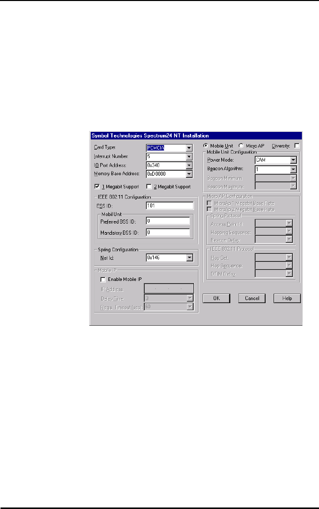
Roaming Across Routers/Mobile IP Setup
Spectrum24 Wireless LAN Adapter Product Reference Guide G 3
3. Select Adapters, select the Symbol Spectrum24 WLAN
Adapter and click the Properties button.
4. When the Symbol Technologies Spectrum24 NT
Installation dialog appears, Select Enable Mobile IP.
Configure all values in the Mobile IP frame. When all
values have been changed click the OK button to save
and exit, click the Cancel button to abort and exit.
G.4 Configuring the Adapter For Mobile IP In DOS
G.4.1 Preparation
Before beginning Mobile IP set up verify or obtain the
following:
•Spectrum24 installation disk
•an ASCII text editor
•home network IP address, home agent IP address,
subnet mask

Roaming Across Routers/Mobile IP Setup
G 4 Spectrum24 Wireless LAN Adapter Product Reference Guide
Copy files MIP.CFG and SLAMIP.COM from the installation
disk to the driver directory. The file MIP.CFG contains
configuration parameters for the Spectrum24 roaming
across routers support. Edit the file before executing
SLAMIP.COM.
The home_address, ha_address, and subnet_mask are
required. The reg_interval is optional. If omitted, the
default value is 60. The maximum value is 1800. An
example of a MIP.CFG file without user configurable
parameters follows:
For ODI, from the command line or in a batch file load the
drivers in the following order:
MIP.CFG example Usage
home_address = xxx.xxx.xxx.xxx MU’s IP address
ha_address = xxx.xxx.xxx.xxx Default home agent's IP address,
used if powered up at a foreign
network
subnet_mask = .xxx.xxx.xxx.xxx
reg_interval = xxxx Registration time between
renewals time is in seconds

Roaming Across Routers/Mobile IP Setup
Spectrum24 Wireless LAN Adapter Product Reference Guide G 5
If the automatic installation program was not used, copy
the files as needed (LSL.COM, SL8ODIPC.COM) from the
Drivers and Utilities Installation diskette to the appropriate
driver directory on the hard disk.
LSL.COM
SL8ODIPC.COM
SLAMIP.COM
Refer to the Spectrum24 Access Point Model AP3020 User
Documentation for details on the Access Point (AP) Mobile
IP support of MUs.

Roaming Across Routers/Mobile IP Setup
G 6 Spectrum24 Wireless LAN Adapter Product Reference Guide

Spectrum24 Wireless LAN Adapter Product Reference Guide H 1
Appendix H Troubleshooting
H.1 Windows 95 Troubleshooting Tips
Use the tools provided by Windows 95, the Spectrum24
DOS/Windows utilities, and LAN analyzers (i.e.
FTP Software LANWATCH, Novell LAN analyzer) to
diagnose problems. Some common problems exhibited
when the Spectrum24 adapter has not been properly
installed include:
•Windows 95 does not recognize the Spectrum24 PC/
ISA card when installed.
– Verify that Windows 95 PCMCIA support
is installed.
– The computer might not have Plug and Play BIOS
or a Spectrum24 ISA adapter in use. The
Spectrum24 ISA adapter is not a Plug and
Play device, it requires manual loading of the
PCMCIA support. Double click on the PC Card
(PCMCIA) applet in the Control Panel to install
PCMCIA support.
•The driver fails to load.
– A resource conflict could exists. Use the Device
Manager to help resolve resource conflicts.
Select the System applet from the Control Panel.
Select the Device Manager tab.
•The workstation cannot attach to the Spectrum24
network.
– Verify that the adapter ESS ID or Net ID settings
match the ESS ID or Net ID of the Access Point.
Refer to the Configuration section of this
document for details.

Troubleshooting
H 2 Spectrum24 Wireless LAN Adapter Product Reference Guide
– Verify that the adapter Data Rate is configured
properly for the AP (refer to the AP Rate Control
Table in this document).
•A degraded performance from the Spectrum24 card.
– Verify a secure connection to Antenna 1 on the PC
Card or Primary Antenna on the WPOS adapter.
– Verify two antennas remain attached to the PC or
ISA adapter if Diversity is selected.
•Network drive mappings disappear when the laptop
suspends or the adapter is removed then reinserted.
Windows 95 does not restore Netware network drive
mappings under these conditions.
– Log out and log in again, or restart the machine
to restore the connections.
•Non-functioning WPOS/ISA adapter LEDs.
–Verify the Card Type parameter is set to
WPOS/ISA.
– Verify that the adapter ESS ID or Net ID setting
matches the ESS ID or Net ID of the Access Point.
H.2 Windows NT 4.0/3.51 Troubleshooting
Make use of the tools provided by Windows NT, the
Spectrum24 DOS/Windows utilities, and LAN analyzers
(i.e. FTP Software LANWATCH, Novell LAN analyzer) to
diagnose problems.
•A resource conflict (usually IRQ or I/O base address)
caused the driver not to load.
–Check SLANT entries in the System Log for hints
on where to look for the conflicts (Windows
NT 3.51).

Troubleshooting
Spectrum24 Wireless LAN Adapter Product Reference Guide H 3
•Check Service Monitor entries in the System Log
for hints on where to look for the conflicts (Windows
NT 4.0).
–Use the Windows NT Diagnostics program to
locate a free resource (Windows NT 4.0). Use the
Network Control Panel applet Configure option to
modify the appropriate key value.
Resource conflicts can exist without an entry in the event
log, when another adapter failed to register its resources.
When no event log entries appear and the Net_ID is
set appropriately, attempt different settings with the
Memory Base Address, Interrupt Number, and IO Port
Address parameters.
•No resource conflicts were detected, but the system
will not attach to the network.
– When using the Symbol protocol, verify the
Net_ID of the Spectrum24 card matches the
Net_ID of the Access Point. Use the Network
Control Panel applet Configure option to modify
the Net_ID setting.
– When using the IEEE 802.11 protocol, verify the
ESS_ID of the Spectrum24 card matches the
ESS_ID of the Access Point. Use the Network
Control Panel applet Configure option to modify
the ESS_ID setting.
– When using the IEEE 802.11 protocol, verify the
Mandatory BSS_ID setting of the Spectrum24 card
is set to 0 or matches the BSS_ID of the Access
Point. Use the Network Control Panel applet
Configure option to modify the Mandatory BSS_ID
setting.

Troubleshooting
H 4 Spectrum24 Wireless LAN Adapter Product Reference Guide
– Verify that the adapter Data Rate is configured
properly for the AP (refer to the AP Rate Control
Table in this document).
•A degraded performance from the Spectrum24 card.
– Verify a secure connection to Antenna 1 on
the PC Card or Primary Antenna on the WPOS
adapter.
– Verify two antennas remain attached to the
PC Card or the ISA adapter when Diversity is
selected.
•Non-functioning WPOS/ISA adapter LEDs.
– Verify that the WPOS/ISA adapter type is selected
in the Card Type field.
– Verify that the adapter ESS ID or Net ID setting
matches the ESS ID or Net ID of the Access Point.
H.2.1 Useful tools
Windows NT Provides other tools for analyzing the network
installation and performance. These include:
PCMCIA.CPL A Control Panel utility that comes with
Windows NT 4.0 or the Windows NT 3.51
Resource Kit. This utility shows information
about the installed PCMCIA card (or WPOS
adapter). If the card is installed, but does
not show in the display it is probably bad.
Performance
Monitor
A Windows NT 3.51 utility (Administrative
Tools group). Configure this utility to
monitor and display protocol activity to/
from the workstation. Various counters
reflect current activity levels, maintained by
the driver and protocol stacks. Refer to the
Windows NT 3.51/4.0 Workstation/Server
documentation for details.

Troubleshooting
Spectrum24 Wireless LAN Adapter Product Reference Guide H 5
H.3 Windows NT ERRORS
Errors during driver loading appear in the System Log.
Use the Event Viewer program from the Administrative
Tools group to view the System Log. For Windows NT 3.51,
find the entries where the Source field indicates the SLANT
driver. In Windows NT 4.0 find SLANT or Service Monitor
entries. If the driver fails to load one of the following
messages will appear in the System Log.
SLANTn is the driver name, where n indicates the nth
network driver installed.
SLANTn: Could not allocate the resources necessary for operation.
•The driver could not allocate enough memory for
internal data.
SLANTn: Has determined that the adapter is not functioning properly.
•The driver could not initialize the Spectrum24 PC Card
or ISA adapter. Possible problems include:
– The Spectrum24 PC Card or ISA adapter firmware
may have been corrupted. Use the DOS-based
firmware update utilities to re-install the firmware
(under DOS).
– The Spectrum24 PC Card or ISA adapter might
have a hardware problem.
– The PCMCIA controller or host bus adapter is
having a problem. Use an alternate PCMCIA
socket or ISA bus slot.
– Windows NT 3.51 may not support the PCMCIA
controller in the machine.
SLANTn: Could not find an adapter.

Troubleshooting
H 6 Spectrum24 Wireless LAN Adapter Product Reference Guide
•The driver could not locate a Spectrum24 PC Card in
any PCMCIA socket or a Spectrum24 ISA adapter in
any ISA bus slot.
– Verify that the Spectrum24 PC Card or ISA
adapter is firmly seated in a PCMCIA socket or
ISA bus slot.
SLANTn: Could not connect to the interrupt number supplied.
•The driver could not claim the configured interrupt.
– The configured interrupt number could be in
use by another adapter. Choose a different
interrupt number.
SLANTn: Does not support the configuration supplied.
•An invalid driver configuration parameter was
specified.
– Use the Configure function of the Network Control
Panel applet to view the driver configuration.
Make sure values appear in each data entry field
(MicroAP parameters will only appear if the
MicroAP check box has been selected). If a value
is missing, key in or use the associated list box to
select an appropriate value.
SLANTn: A required parameter is missing from the Registry.
•A required configuration parameter was not found in
the system registry.
– Use the Configure function of the Network Control
Panel applet to view the driver configuration.
Make sure values appear in each data entry field
(MicroAP parameters will only appear if the
MicroAP check box has been selected). If a value
is missing, key in or use the associated list box to
select an appropriate value.

Spectrum24 Wireless LAN Adapter Product Reference Guide Index - 1
Numerics
1 and 2 Mbps
Configuration 6
A
ACL (Access Control List) 5
Antenna
Diversity 39
DOS Configuration 20
End-Cap Installation 16
End-Cap Removal 16
Installation 13
Options 3
Diversity 20
End-Cap 16
External 19
Plane 19
Parameters 20
AP (Access Point) 4
Rate Control 6
Roaming 8
B
BIOS (Basic Input Output System) 3
C
CAM (Continuously Aware Mode)
Power Management 3, 8
CardServices
Enabling 60
Configuration
1 and 2 Mbps 6
Mobile IP 8
Rate Control 6
Roaming 8
CSS (Card and Socket Services)
Plug and Play 3
Wireless LAN 9
Customer Support
Additional Information x
International Contacts ix
North American Contacts ix
D
Data Rates
MicroAP 6
DOS (Disk Operating System)
Conflicts 53
Driver Installation 53
Memory Manager 53
Driver Installation
Introduction 23
Driver Update
Windows NT 3.51 49
Windows NT 4.0 49
Dynamic Rate Control 6
E
ESS_ID (Extended Service Set
Identification) 5
External Antenna
Installation 19
F
Firmware
ISA 21
PC Card 21
Update 21
Index

Index - 2 Spectrum24 Wireless LAN Adapter Product Reference Guide
Version 21
Frequency-Hopping 1
H
Hardware
Installation 13
I
I/O (Input/Output) 3
Installation
Antenna 13
End-Cap Antenna 16
External Antenna 19
Hardware 13
ISA Adapter 13, 18
PC Card 13
Utilities 13
Windows 95 Driver 23, 26
Windows NT Driver 31
IRQ (Interrupt Request) 3
ISA (Industry Standard Architecture)
Adapter
Firmware 21
Installation 13, 18
Plug and Play
SLAINIT.EXE 21
Wireless LAN 3, 18
ISA Adapter
Plug and Play 3
M
MAC (Media Access Control)
Address 5
Mbps (Megabits per second) 6
MicroAP
Data Rates 6
ESS_ID 5
Operation 5
Rate Control 6
Rate Control Table 6
Mobile IP (Internet Protocol)
Configuration 8
Roaming 8
Modifying
Config.sys 56
Net.cfg 58
Protocol.ini 57
MU (Mobile Unit)
Operation 4
Rate Control 6
Roaming 8
N
NDIS (Network Driver Interface
Specification) 3
Automated Installation 54
Keywords 6
Manual Installation 55
Modifying Autoexec. bat 56
Net ID (Net Identification) 28
Network Adapter
Configuration
Windows NT 3.51 49, 50
Windows NT 4.0 49, 50
Network Installation
Windows NT 3.51 43
Windows NT 4.0 43
O
ODI (Open Data-Link Interface) 3
Installation 54
Keywords 6
Manual Installation 57
Modifying Autoexec. bat 58

Spectrum24 Wireless LAN Adapter Product Reference Guide Index - 3
P
PC Card
Alignment 14
Antenna Installation 16
Antenna Removal 16
Firmware 21
Installation 13
Plug and Play 3
Wireless LAN 3
PCMCIA (Personal Computer
Memory Card International
Association) 18
Plug and Play 9
BIOS 3
CSS 3
Enabling 59
ISA Adapter 3
PC Card 3
Power Management
CAM 3, 8
PSP 3, 8
Wireless LAN 9
PSP (Power Save Polling)
Power Management 3, 8
R
Rate Control 6
AP 6
Configuration 6
MicroAP 6
MU 6
Roaming
AP 8
Configuration 8
Mobile IP 8
MU 8
S
Spectrum24
802.11 1
Bridging Architecture 1
DOS
Driver Installation 54
Firmware 21
Introduction 1
LED Functions 9
Roaming 1
Switchable Data Rates 1
Spread Spectrum 1
Spring Protocol
Net ID 28
Supported System Software 11
U
Utilities
Installation 13
W
Windows 95
Driver
Configuration 30
Features 24
Installation 23
Setup 29
Transport Updates 24
Uninstall 25
Driver Installation 26
802.11 Protocol 28, 29
OSR2 Version 27
Retail Version 26
Spring Protocol 28, 29
Non-Plug and Play 26
Windows for Workgroups (v3.11)
Driver Installation 62

Index - 4 Spectrum24 Wireless LAN Adapter Product Reference Guide
Windows NT
Driver Features 32
Driver Installation 31
Limitations 33
Windows NT 3.51
Server Installation 36, 40
Workstation Installation 36, 40
Windows NT 4.0
Server Installation 33, 38
Workstation Installation 33, 38
Wireless LAN (Local Area Network)
Adapter 4
CSS 9
ISA Adapter 3, 18
PC Card 3
Power Management 9
Wireless LAN ISA Adapter
Model 3025 9
Wireless LAN PC Card
Model 3020 9
WPOS (Wireless Point of Sale) 28