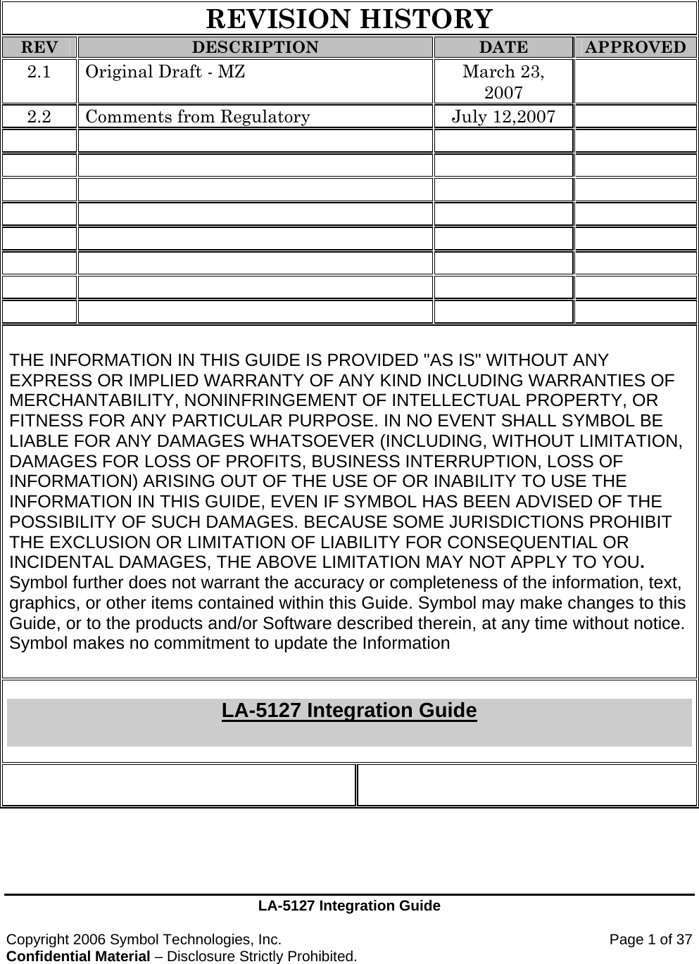
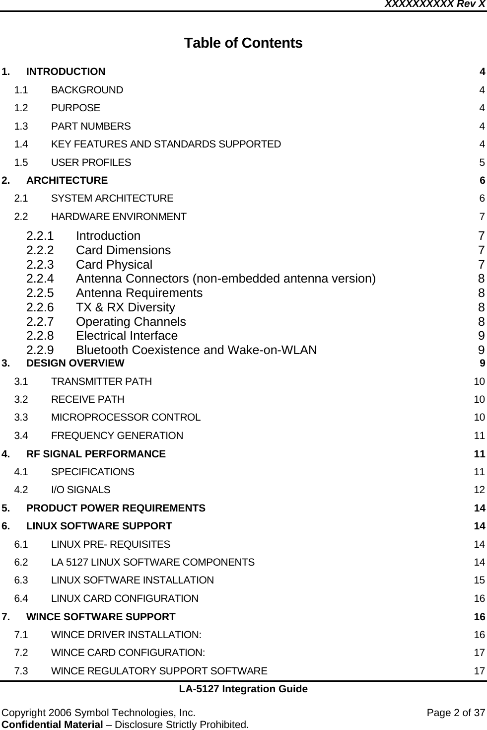
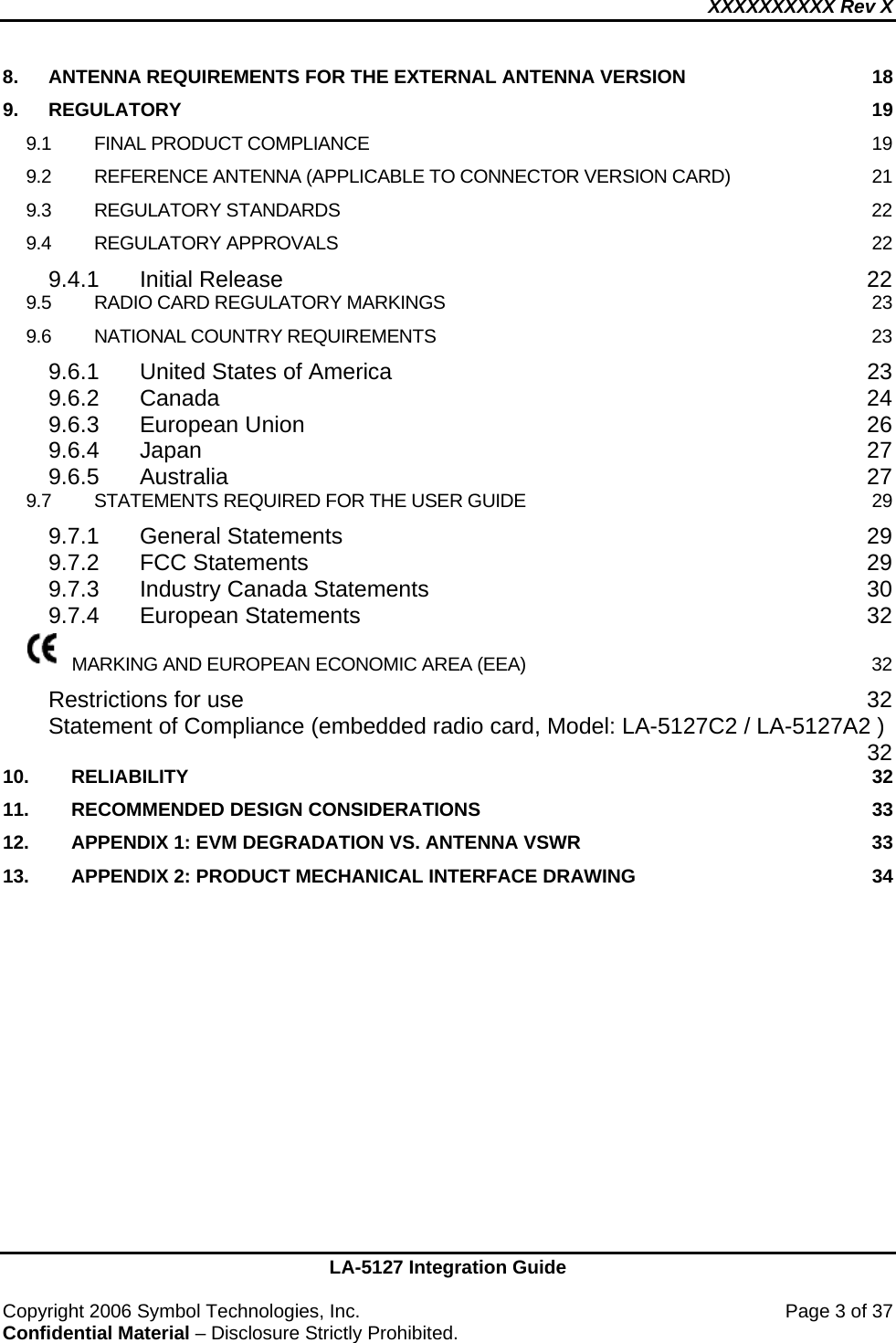
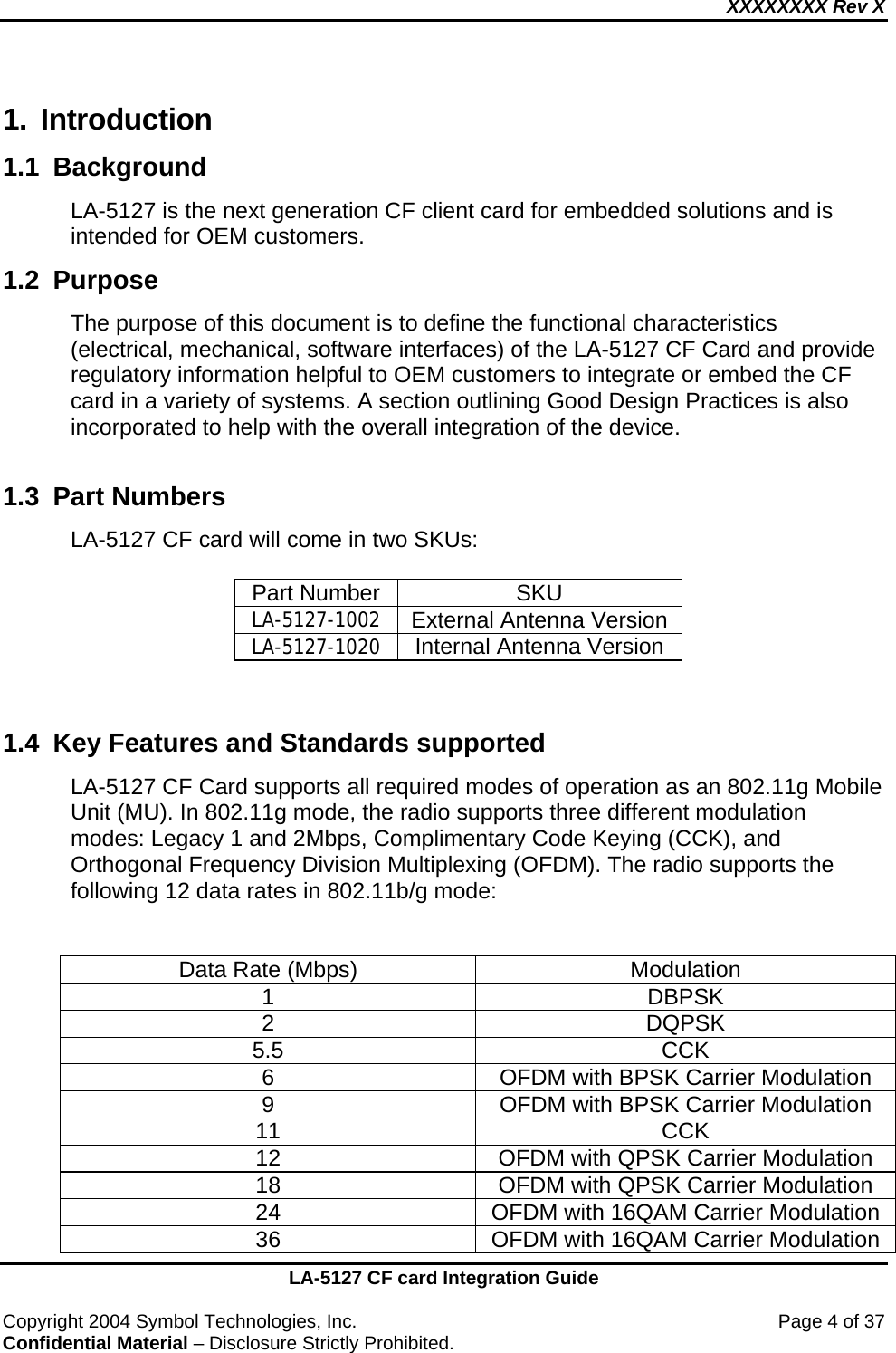
Symbol Technologies LA5127A2 802.11b/g Compact Flash Radio Card User Manual LA 5127 Integration Guide

Symbol Technologies Inc 802.11b/g Compact Flash Radio Card LA 5127 Integration Guide

User manual revised

LA-5127 Integration Guide  Copyright 2006 Symbol Technologies, Inc.    Page 1 of 37 Confidential Material – Disclosure Strictly Prohibited.   REVISION HISTORY REV DESCRIPTION DATE APPROVED 2.1  Original Draft - MZ  March 23, 2007  2.2  Comments from Regulatory  July 12,2007                                                   THE INFORMATION IN THIS GUIDE IS PROVIDED "AS IS" WITHOUT ANY EXPRESS OR IMPLIED WARRANTY OF ANY KIND INCLUDING WARRANTIES OF MERCHANTABILITY, NONINFRINGEMENT OF INTELLECTUAL PROPERTY, OR FITNESS FOR ANY PARTICULAR PURPOSE. IN NO EVENT SHALL SYMBOL BE LIABLE FOR ANY DAMAGES WHATSOEVER (INCLUDING, WITHOUT LIMITATION, DAMAGES FOR LOSS OF PROFITS, BUSINESS INTERRUPTION, LOSS OF INFORMATION) ARISING OUT OF THE USE OF OR INABILITY TO USE THE INFORMATION IN THIS GUIDE, EVEN IF SYMBOL HAS BEEN ADVISED OF THE POSSIBILITY OF SUCH DAMAGES. BECAUSE SOME JURISDICTIONS PROHIBIT THE EXCLUSION OR LIMITATION OF LIABILITY FOR CONSEQUENTIAL OR INCIDENTAL DAMAGES, THE ABOVE LIMITATION MAY NOT APPLY TO YOU. Symbol further does not warrant the accuracy or completeness of the information, text, graphics, or other items contained within this Guide. Symbol may make changes to this Guide, or to the products and/or Software described therein, at any time without notice. Symbol makes no commitment to update the Information   LA-5127 Integration Guide
XXXXXXXXXX Rev X    LA-5127 Integration Guide  Copyright 2006 Symbol Technologies, Inc.    Page 2 of 37 Confidential Material – Disclosure Strictly Prohibited.  Table of Contents  1. INTRODUCTION  4 1.1 BACKGROUND  4 1.2 PURPOSE  4 1.3 PART NUMBERS  4 1.4 KEY FEATURES AND STANDARDS SUPPORTED  4 1.5 USER PROFILES  5 2. ARCHITECTURE  6 2.1 SYSTEM ARCHITECTURE  6 2.2 HARDWARE ENVIRONMENT  7 2.2.1 Introduction 7 2.2.2 Card Dimensions  7 2.2.3 Card Physical  7 2.2.4 Antenna Connectors (non-embedded antenna version)  8 2.2.5 Antenna Requirements  8 2.2.6 TX & RX Diversity  8 2.2.7 Operating Channels  8 2.2.8 Electrical Interface  9 2.2.9 Bluetooth Coexistence and Wake-on-WLAN  9 3. DESIGN OVERVIEW  9 3.1 TRANSMITTER PATH  10 3.2 RECEIVE PATH  10 3.3 MICROPROCESSOR CONTROL  10 3.4 FREQUENCY GENERATION  11 4. RF SIGNAL PERFORMANCE  11 4.1 SPECIFICATIONS  11 4.2 I/O SIGNALS  12 5. PRODUCT POWER REQUIREMENTS  14 6. LINUX SOFTWARE SUPPORT  14 6.1 LINUX PRE- REQUISITES  14 6.2 LA 5127 LINUX SOFTWARE COMPONENTS  14 6.3 LINUX SOFTWARE INSTALLATION  15 6.4 LINUX CARD CONFIGURATION  16 7. WINCE SOFTWARE SUPPORT  16 7.1 WINCE DRIVER INSTALLATION:  16 7.2 WINCE CARD CONFIGURATION:  17 7.3 WINCE REGULATORY SUPPORT SOFTWARE  17
XXXXXXXXXX Rev X    LA-5127 Integration Guide  Copyright 2006 Symbol Technologies, Inc.    Page 3 of 37 Confidential Material – Disclosure Strictly Prohibited.  8. ANTENNA REQUIREMENTS FOR THE EXTERNAL ANTENNA VERSION  18 9. REGULATORY  19 9.1 FINAL PRODUCT COMPLIANCE  19 9.2 REFERENCE ANTENNA (APPLICABLE TO CONNECTOR VERSION CARD)  21 9.3 REGULATORY STANDARDS  22 9.4 REGULATORY APPROVALS  22 9.4.1 Initial Release  22 9.5 RADIO CARD REGULATORY MARKINGS  23 9.6 NATIONAL COUNTRY REQUIREMENTS  23 9.6.1 United States of America  23 9.6.2 Canada 24 9.6.3 European Union  26 9.6.4 Japan 27 9.6.5 Australia 27 9.7 STATEMENTS REQUIRED FOR THE USER GUIDE  29 9.7.1 General Statements  29 9.7.2 FCC Statements  29 9.7.3 Industry Canada Statements  30 9.7.4 European Statements  32 MARKING AND EUROPEAN ECONOMIC AREA (EEA)  32 Restrictions for use  32 Statement of Compliance (embedded radio card, Model: LA-5127C2 / LA-5127A2 ) 32 10. RELIABILITY  32 11. RECOMMENDED DESIGN CONSIDERATIONS  33 12. APPENDIX 1: EVM DEGRADATION VS. ANTENNA VSWR  33 13. APPENDIX 2: PRODUCT MECHANICAL INTERFACE DRAWING  34
XXXXXXXX Rev X    LA-5127 CF card Integration Guide  Copyright 2004 Symbol Technologies, Inc.    Page 4 of 37 Confidential Material – Disclosure Strictly Prohibited. 1. Introduction 1.1 Background  LA-5127 is the next generation CF client card for embedded solutions and is intended for OEM customers. 1.2 Purpose  The purpose of this document is to define the functional characteristics (electrical, mechanical, software interfaces) of the LA-5127 CF Card and provide regulatory information helpful to OEM customers to integrate or embed the CF card in a variety of systems. A section outlining Good Design Practices is also incorporated to help with the overall integration of the device.  1.3  Part Numbers  LA-5127 CF card will come in two SKUs:  Part Number  SKU LA-5127-1002 External Antenna Version LA-5127-1020  Internal Antenna Version   1.4  Key Features and Standards supported LA-5127 CF Card supports all required modes of operation as an 802.11g Mobile Unit (MU). In 802.11g mode, the radio supports three different modulation modes: Legacy 1 and 2Mbps, Complimentary Code Keying (CCK), and Orthogonal Frequency Division Multiplexing (OFDM). The radio supports the following 12 data rates in 802.11b/g mode:   Data Rate (Mbps)  Modulation 1 DBPSK 2 DQPSK 5.5 CCK 6  OFDM with BPSK Carrier Modulation 9  OFDM with BPSK Carrier Modulation 11 CCK 12  OFDM with QPSK Carrier Modulation 18  OFDM with QPSK Carrier Modulation 24  OFDM with 16QAM Carrier Modulation 36  OFDM with 16QAM Carrier Modulation
XXXXXXXX Rev X    LA-5127 CF card Integration Guide  Copyright 2004 Symbol Technologies, Inc.    Page 5 of 37 Confidential Material – Disclosure Strictly Prohibited. 48  OFDM with 64QAM Carrier Modulation 54  OFDM with 64QAM Carrier Modulation   LA-5127 CF Card supports station operation in Continuous Aware Mode (CAM) and Fast Power-Save and Max Power-Save modes.  Other features and standards supported:  • 802.11b/g • 802.11d •  Robust roaming and dynamic rate switching •  Range up to 300 ft./91m in standard office environments •  Data security using WEP data encryption and Wireless Protected Access (WPA) and 802.11i (WPA2) with advance encryption standard (AES) • Advance authentication using 802.1x •  Advanced Power Management for very low power consumption •  16 bit host interface using CF mode (16-bit PC-Card® Interface) •  Driver/Firmware supports Linux 2.4 and Windows CE Embedded 5.0 1.5  User Profiles  • The LA-5127 product is optimized for embedded, mobile enterprise and industrial applications where security, feature and technical service are required.  • Mobile workers in healthcare, education, retail, manufacturing, hospitality and other industries with 802.11b, and 802.11g wireless LAN access.  • Corporate Symbol device users with Wi-Fi wireless LAN access at the office, or with a subscription to a public wireless LAN.
XXXXXXXX Rev X    LA-5127 CF card Integration Guide  Copyright 2004 Symbol Technologies, Inc.    Page 6 of 37 Confidential Material – Disclosure Strictly Prohibited. 2. Architecture  2.1 System Architecture Figure 1 depicts the top-level architecture of the LA-5127 CF card.                            Figure 1   As shown, LA-5127 CF card consists of all of the integrated circuits necessary to provide WLAN transceiver functionality for 2.4GHz band. The Wireless LAN integrated Media Access Controller with Baseband processor directly interfaces with the Dual Band Direct Conversion transceiver. With the addition of RF Front-end Module (FEM), LA-5127 CF card incorporates the WLAN chip set solution compliant with 802.11b/g standards.  The 40MHz crystal controlled clock provides the necessary clocks for both the PLL and the baseband & MAC chip. The SDRAM provides additional memory to support SHoC (Self Hosted Client) operation. Not shown in the figure are the necessary voltage regulators that provide various supply voltages for the chips. The regulators require 3.3V input supply.  The EEPROM is used to hold radio information including radio calibration information done at the automatic manufacturing test step.      2.4GHz Transceiver  CF Host I/F RF FEM  Baseband & MAC 40Mhz Clock EEPROM SDRAM  32.768Khz Clock To Antenna (Antenna Version) To RF Connectors (Connector Version)
XXXXXXXX Rev X    LA-5127 CF card Integration Guide  Copyright 2004 Symbol Technologies, Inc.    Page 7 of 37 Confidential Material – Disclosure Strictly Prohibited.  2.2 Hardware Environment 2.2.1 Introduction   LA-5127 CF card can be used in handheld mobile devices to provide wireless network access. LA-5127 communicates using Radio Frequencies (RF) between two or more users or between a user and the wired network. The module implements the IEEE802.11g physical (RF) specification. The chipset used provides for modulation, demodulation, spreading and despreading of the RF signals. 2.2.2 Card Dimensions  LA-5127 is a modified type I CFA card. See Appendix 2 for Mechanical Interface Drawing.  2.2.3 Card Physical 2.2.3.1 Operational Environment (Note: The product is not required to be powered during test activities. Only parameters marked by an * shall be powered during testing. Testing per Symbol Qualification Test Standard SS-03800-74.)  •  0 to +55 degrees C max operating* (card installed environment) •  95% RH non-condensing* •  Altitude to withstand 8,000 ft @ 28 degrees Celsius* •  Vibration to withstand .02g2/Hz, random, sine, 20-2k Hz •  Bench drop 36 inches to concrete @ -20, 23, 50 degrees Celsius  •  Mechanical shock to withstand 50 G peak, 11 ms, half sine •  Card bend to withstand 4.4lbs, 1 min, per PCMCIA STD 3.6.2.14 •  Card torque to withstand 11 in.-lbs., per PCMCIA STD 3.6.2.16 •  No water/rain/insect resistance (Damp cloth cleaning OK) •  No chemical resistance (Light cleaning solutions OK) •  Loose cargo/packaged to withstand 6 foot drop •  ESD to withstand  1.5KV contact per PCMCIA/CF Specification
XXXXXXXX Rev X    LA-5127 CF card Integration Guide  Copyright 2004 Symbol Technologies, Inc.    Page 8 of 37 Confidential Material – Disclosure Strictly Prohibited. 2.2.3.2 Storage Environment •  -20 to +65 degrees C temperature range •  95% RH non-condensing humidity •  Altitude to withstand 15,000 ft 2.2.4  Antenna Connectors (non-embedded antenna version)  LA-5127-1002 CF card (External Antenna Version) supports 2 RF connectors (Hirose U.FL-R-SMT, or equivalent). The antennas can be attached to the card through the connectors.  There are two connectors on the LA-5127-1002 unit.  Note on sharing antennas: Antenna sharing with other radio modules is not supported on LA-5127 with other radio modules. 2.2.5 Antenna Requirements  For detailed antenna requirements please refer to section 8.1.3.  Regulatory Note: Many country regulations require special testing and reporting of antenna performance or of the system with the antenna attached. Please check the appropriate regulatory authority or contact Symbol for more information.   2.2.6  TX & RX Diversity  TX & RX Diversity is only supported on the connector version of the LA-5127 (LA-5127-1002). 2.2.7 Operating Channels  Channel Number  Channel Frequency (MHz) Countries 1  2412  USA, Canada, EU, Japan 2  2417  USA, Canada, EU, Japan 3  2422  USA, Canada, EU, Japan 4  2427  USA, Canada, EU, Japan 5  2432  USA, Canada, EU, Japan 6  2437  USA, Canada, EU, Japan 7  2442  USA, Canada, EU, Japan 8  2447  USA, Canada, EU, Japan 9  2452  USA, Canada, EU, Japan 10  2457  USA, Canada, EU, Japan
XXXXXXXX Rev X    LA-5127 CF card Integration Guide  Copyright 2004 Symbol Technologies, Inc.    Page 9 of 37 Confidential Material – Disclosure Strictly Prohibited. 11  2462  USA, Canada, EU, Japan 12 2467  EU, Japan 13 2472  EU, Japan 14 2484  Japan  Table 1. IEEE 802.11g Channels  2.2.8 Electrical Interface  The electrical interface for LA-5127 is PC16. The chipset used supports this interface; therefore no external component is required. The host must support the PC16 interface as well.  The card uses only the 16-bit interface.  2.2.9 Bluetooth Coexistence and Wake-on-WLAN    LA-5127 hardware is being designed to support these features for future software implementation. AT THIS TIME THESE FEATURES ARE NOT SUPPORTED BY THE SOFTWARE.  Three GPIO pins have been assigned to support the BT Coexistence. The following is the assignment to support the BT Coexistence with Broadcom’s BCM2045 BT module:  GPIO 2-3: BT0 (Tx Config) (Connected to pin A10 on CF interface) GPIO 2-4: BT1 (Status) (Connected to pin CSEL on CF interface)  GPIO 2-5: BT2 (RF Active) (Connected to pin SPKR on CF interface)  The following GPIO signal is also available for Wake-on-WLAN functionality:  GPIO 2-11:  WOL (Connected to STSCHG on CF interface)   3. Design Overview  The chipset used implements a dual band direct conversion transceiver supporting 2.4GHz band. The chipset uses “Zero Intermediate Frequency (ZIF) architecture for the radio. The architecture contains low-noise amplifiers, quad up/down converters, frequency synthesizers, low-pass filters, baseband AGC receiver amplifiers, transmit/receive switches, and transmitter power amplifiers.
XXXXXXXX Rev X    LA-5127 CF card Integration Guide  Copyright 2004 Symbol Technologies, Inc.    Page 10 of 37 Confidential Material – Disclosure Strictly Prohibited.  The 802.11 WLAN MAC protocol is implemented in firmware supporting BSS and IBSS operation. Low-level protocol functions such as request to send (RTS)/clear to send (CTS) generation and acknowledgement, fragmentation and de-fragmentation, and automatic beacon monitoring are handled without host intervention. 3.1  Transmitter Path   After the Medium Access Controller (MAC) receives the data from the host computer through CF interface, the MAC appends a preamble and header and sends the data to the Base-Band Processor (BBP).   The radio supports the legacy and CCK data rates in 2.4GHz and the OFDM data modulation modes for 2.4GHz band.  The CCK mode transmitter is a Direct Sequence Spread Spectrum (DSSS) PSK modulator when in CCK mode supporting 5.5Mbps and 11Mbps. It also supports DBPSK for 1Mbps and DQPSK for 2Mbps. The preamble is always transmitted as the DBPSK waveform and the header can be configured as DBPSK or DQPSK while the data packets can be DBPSK, DQPSK, or CCK.  The OFDM transmitter supports BPSK, QPSK, 16QAM or 64QAM modulation. The OFDM transmitter operates in 2.4GHz band providing 6, 9, 12, 18, 24, 36, 48, and 54Mbps data rates. The OFDM signal is fed to a pair of Digital to Analog Converters (DACs) to produce the In Phase (I) and the Quadrature (Q) signals. The TX signals are then amplified by the PA and routed through the diplexer to the dual band antenna for transmission.   3.2 Receive Path   The received signal from the antenna is fed to the diplexer, which separates the signal path for the low band (2.4GHz) and the high band (5.2GHz). The signal is then fed to a filter/balun in the low band and to a balun in the high band path. The signal then goes to the transceiver chip for direct down conversion for both low and high bands. The design contains LNAs, Quad Up/Down Converters, Synthesizers, Low-Pass Filters, and Baseband AGC Receiver Amplifiers.   3.3  Microprocessor Control
XXXXXXXX Rev X    LA-5127 CF card Integration Guide  Copyright 2004 Symbol Technologies, Inc.    Page 11 of 37 Confidential Material – Disclosure Strictly Prohibited. The baseband and MAC chip contains an ARM946E processor core and the SRAM required for implementing the Media Access Control (MAC) functionality. The embedded firmware runs the 802.11 MAC layer control. The MAC control sends and receives packets and transfers data to and from the CF interface to the host computer of the handheld device.  3.4 Frequency Generation  The MAC & Baseband chip has the voltage-controlled oscillator (VCO) required for the design. The VCO operates in one of the two ranges: 9648 to 9936MHz (4X channel frequency for low-band) or 9900 to 11,800MHz (2X channel frequency for high band). The Synthesizer circuit uses the 40MHz crystal oscillator to phase lock the VCO to produce accurate channel frequency for the radio. The frequency range in the low-band is covered in two MHz steps (1MHz at the channel frequency) and in the high-band the LO frequency is covered in five MHz steps (2.5MHz at the channel frequency).  4. RF Signal Performance  4.1 Specifications  Unless otherwise stated the following specifications hold over 0C to +55C, and 3.3V +/- 5%. This environment is defined as the specific temperature envelope containing the LA-5127 radio product. If embedded within a host product, this envelope is the internal ambient temperature of the host under the hosts operating conditions.    Description  Typ  Max  Unit       Comments Functional Continuous Transmit Current (OFDM 54Mbps)  481 580 mA  Continuous Transmit Current (CCK/DS 11Mbps)  501 600 mA  Continuous Receive Current (OFDM 54Mbps)  281 340 mA  Continuous Receive Current (CCK/DS 11Mbps)  281 340 mA  Continuous Ping (10,000 size) TX 54Mbps  328 390 mA  Continuous Ping (10,000 size) RX 54Mbps  304 370 mA  Max in-rush current  165  200  mA   Supply Voltage  3.13 3.47 Volts
XXXXXXXX Rev X    LA-5127 CF card Integration Guide  Copyright 2004 Symbol Technologies, Inc.    Page 12 of 37 Confidential Material – Disclosure Strictly Prohibited. Receiver (“Legacy” 802.11b mode): Sensitivity, 11 Mbps  -79  -10 Sensitivity, 5.5 Mbps  -82  -10 Sensitivity, 2 Mbps  -83  -10 Sensitivity, 1 Mbps   -86  -10 dBm  8% PER 1024 Octets 0C to 55C Transmitter (“Legacy” 802.11b mode): Power Level,  0C to +55C   12 16 dBm RF Power will have the appropriate back-off to meet the regulatory requirements at the band edges. Receiver (802.11g OFDM mode): Sensitivity, 54 Mbps  -65  -15 Sensitivity, 48 Mbps  -66  -15 Sensitivity, 36 Mbps  -70  -15 Sensitivity, 24 Mbps   -74  -15 Sensitivity, 18 Mbps  -77  -15 Sensitivity, 12 Mbps  -79  -15 Sensitivity, 9 Mbps  -81  -15 Sensitivity, 6 Mbps   -82  -15 dBm  10% PER for 1000 bytes 0C to +55C Transmitter (802.11g OFDM mode): Power Level, 54Mbps  10  12 Power Level, 48Mbps  10  12 Power Level, 36Mbps  11  13 Power Level, 24Mbps  11  13 Power Level, 18Mbps  12  15 Power Level, 12Mbps  12  15 Power Level, 9Mbps  13  16 Power Level, 6Mbps  13  16 dBm Power output measured at relative constellation error specifications. IEEE 802.11g, 17.3.9.6.3 0C to +55C  RF Power will have the appropriate back-off to meet the regulatory requirements at the band edges.    4.2  I/O Signals  The following table describes the I/O signals for I/O mode operation:  Pin #  Signal Name  Pin Type 1 GND DC In 2 D03 I/O 3 D04 I/O 4 D05 I/O 5 D06 I/O 6 D07 I/O 7 CE1J I 8 A10 I 9 OEJ I 10 A09  I 11 A08  I 12 A07  I
XXXXXXXX Rev X    LA-5127 CF card Integration Guide  Copyright 2004 Symbol Technologies, Inc.    Page 13 of 37 Confidential Material – Disclosure Strictly Prohibited. 13 VCC DC In 14 A06  I 15 A05  I 16 A04  I 17 A03  I 18 A02  I 19 A01  I 20 A00  I 21 D00 I/O 22 D01 I/O 23 D02 I/O 24 WP / IOIS16J O 25 CD2J  O 26 CD1J  O 27 D11 I/O 28 D12 I/O 29 D13 I/O\ 30 D14 I/O 31 D15 I/O 32 CE2J  I 33 VS1J  O 34 IORDJ  I 35 IOWRJ  I 36 WEJ  I 37  RDYJ / BSYJ / IREQJ  Out 38 VCC DC In 39 CSELJ  I 40 VS2J  O 41 RESET  I 42 WAITJ  O 43 INPACKJ  O 44 REGJ  I 45 SPKRJ I/O 46 STSCHGJ I/O 47 D08 I/O 48 D09 I/O 49 D10 I/O 50 GND DC In   Please refer to the Mechanical Drawing section (Appendix 2) for Pin orientation.
XXXXXXXX Rev X    LA-5127 CF card Integration Guide  Copyright 2004 Symbol Technologies, Inc.    Page 14 of 37 Confidential Material – Disclosure Strictly Prohibited. 5. Product Power Requirements Depends on operating mode, network/traffic load and platform implementation. The following table lists the typical current consumption under the specified usage model:  Usage Model  Current Consumption (mA) (5sec average) Power Save Idle   17  CAM mode (20% TX duty cycle)  298 CAM mode (20% RX duty cycle)  296  6. Linux Software Support  6.1 Linux Pre- Requisites The following are the pre-requisites needed to bring up the LA 5127 CF adapter under Linux environment:  1.  PCMCIA enabled in the kernel 2.  Linux kernel 2.4.22 or later 3.  Netlink enabled in the kernel if WPA supplicant is to be used 4.  Compiler and make utilities to build the driver, wireless tools, WPA supplicant and OpenSSL sources  6.2  LA 5127 Linux Software Components  1.  Driver sources The drivers will be supported on Red Hat 9 distribution of Linux based on 2.4 kernels. Sources for the driver will be provided. 2.  Firmware Binary Firmware binary which has the complete 802.11 MAC implementation for LA 5127 adapter. 3.  Sample applications - getoid, setoid These are used for configuration and monitoring the adapter. These applications invoke the APIs (OIDs) to set or get information from the adapter. Refer to the API  Reference Guide document for further information. 4.  OpenSSL sources
XXXXXXXX Rev X    LA-5127 CF card Integration Guide  Copyright 2004 Symbol Technologies, Inc.    Page 15 of 37 Confidential Material – Disclosure Strictly Prohibited. OpenSSL sources in tar.gz  format. OpenSSL is a cryptography toolkit implementing the Secure Sockets Layer (SSL v2/v3) and Transport Layer Security (TLS v1) network protocols and related cryptography standards required by them. 5.  Wireless Tools sources These are a set of tools that controls the LA-5127 adapter using   Wireless Extensions API. 6.  WPA Supplicant sources WPA supplicant is the IEEE 802.1X / WPA component that is used in the client stations. It implements key negotiation with a WPA Authenticator and it controls the IEEE 802.11 authentication / association of the wireless LAN driver.  This supplicant sources will also include a LA 5127 “WPA driver”, so that the WPA supplicant can work seamlessly with the LA 5127 adapter. 7. Documents • LA 5127 User Guide This document provides information needed to install and configure the software for LA 5127 adapter • LA 5127 API Reference Guide This document provides information to invoke the APIs (OIDs) to get or set information on the LA 5127 adapter • LA 5127 Host Interface Guide This document gives the details on how the host interfaces with LA 5127 adapter • LA 5127 Integration Guide    6.3 Linux Software Installation  A tar.gz package will contain the driver sources for LA 5127 adapter for Linux Red Hat 9 distribution. The driver shall be compiled from the release package and installed (see README file).  The LA5127 User Guide gives detailed instructions on the installation of :  • Driver  • PCMCIA • Hotplug  •  WPA Supplicant  • Wireless Tools • OpenSSL •  Linux kernel 2.4.31
XXXXXXXX Rev X    LA-5127 CF card Integration Guide  Copyright 2004 Symbol Technologies, Inc.    Page 16 of 37 Confidential Material – Disclosure Strictly Prohibited.  6.4  Linux Card Configuration LA 5127 adapter supports Wireless Extensions API  in Linux. The OEMs can use the standard Wireless Extensions API to configure LA 5127 adapter                       OR Use the driver APIs to configure the card through application sample getoid / setoid programs. LA 5127 API Reference Guide gives detailed description of APIs.  Refer to the LA 5127 User Guide, for configuring the card, and it involves :  •  Configuring card services • Configuring hotplug •  Configuring WPA supplicant •  Configuring card/driver using Wireless Tools •  Configuring card/driver using getoid / setoid OR API’s  7. WinCE Software Support Driver support for the 5127 radio is available for Windows CE Embedded 5.0.  The supplied driver has been compliled for and ARMV4I processor.   If the OEM wishes to have drivers for specific operating systems not currently supported, Symbol provides custom software development services. A development and support contract needs to be worked through in conjunction with the local OEM account manager. The OEM can leverage Symbol’s extensive expertise in Wireless LAN development and maximize benefits.   7.1  WinCE Driver Installation: The 5127 NDIS miniport driver are released as a set of platform flash images.  The OS platform is the delivery mechanism therefore an isolated install of the software is not required.
XXXXXXXX Rev X    LA-5127 CF card Integration Guide  Copyright 2004 Symbol Technologies, Inc.    Page 17 of 37 Confidential Material – Disclosure Strictly Prohibited. 7.2  WinCE Card Configuration: Device configuration is made using a built-in Microsoft OS WLAN configuration service (i.e. a utility) commonly known as Wireless Zero Configuration (WCZ).  WZC allows a wireless device to connect to an existing wireless network, change wireless network connection settings, configure a new wireless network connection, and specify preferred wireless networks.  WZC will also notify the user when new wireless networks are available.  Once a desired wireless network is selected, WZC will automatically configure the wireless card to match the setting of the network and will attempt a network connection. 7.3  WinCE Regulatory Support Software The WinCE™ 5.0 regulatory support consists of the functionality of the cTxRx (Continuous Transmit and Receive) application that runs on Full Windows.  The CEcTxRx communicates with the Symbol transport driver that in turn communicates with the Conexant’s Manufacturing and Test Upper MAC (MTUM) driver to give the application control of the Photon hardware.  The CEcTxRx application provides configuration file based control that sets up the radio to produce continuous transmission of random patterns, continuous transmission of single tone (CW), continuous transmission of predefined packets with a settable interval between the packets, and continuous reception of 802.11 type packets.    Regulatory testing can also be achieved using a remote application for platforms that have small or no displays.  This is done using a RAPI connection over the USB.  It allows a remote application running on a Windows computer to control the radio in the same way as the CEcTxRx application.
XXXXXXXX Rev X    LA-5127 CF card Integration Guide  Copyright 2004 Symbol Technologies, Inc.    Page 18 of 37 Confidential Material – Disclosure Strictly Prohibited.  8. Antenna requirements for the external antenna version The following table summarizes the guidelines for the Antenna design:     Comments Frequency Bands     2.4 GHz to 2.5 GHz Required for 802.11g support Nominal Impedance  50 ohms  VSWR  Less than 2.0:1 Across bands Gain (Peak)   2.1dBi   Includes coax cable/connector RF losses  Vertical component or Horizontal
XXXXXXXX Rev X    LA-5127 CF card Integration Guide  Copyright 2004 Symbol Technologies, Inc.    Page 19 of 37 Confidential Material – Disclosure Strictly Prohibited. 9. Regulatory Legal Disclaimer: This Guide may contain information on regulatory matters.  The information should be used with the understanding that Symbol is not engaged in rendering any legal, regulatory or other professional opinion.  Each country has specific laws and regulations governing the use of radio communications.  Please consult the official code for each country of interest.  Symbol does not warrant the accuracy of the information contained herein and accepts no liability or responsibility for any use or misuse of the information  Symbol’s wireless network devices are designed to be compliant with rules and regulations in locations they are sold.   Any changes or modifications to Symbol Technologies equipment, not expressly approved by Symbol Technologies, could void the user’s authority to operate the equipment.   The OEM integrator must NOT provide information in the user guide of the end product regarding how to install or remove this RF module.   9.1  Final Product Compliance The model numbers used for Regulatory Approvals are: LA-5127C2 (connector version)  LA-5127A2 (antenna version)  The LA-5127 has been regulatory approved for OEM integrations which meet the following conditions:  1.  The radio integration is embedded 2.  The antenna must be installed such that 20 cm is maintained between the antenna and users 3.  The ‘Type’ and ‘Gain’ of the antenna selected for the integration of the external antenna must meet the requirements as detailed in section 9.2.  Used outside of these conditions will trigger re-approval.  Symbol advises the use of an accredited test laboratory for advice. Be prepared, the certification process for your product may take from a few weeks to several months.
XXXXXXXX Rev X    LA-5127 CF card Integration Guide  Copyright 2004 Symbol Technologies, Inc.    Page 20 of 37 Confidential Material – Disclosure Strictly Prohibited. AS THE INTEGRATOR, YOU ARE RESPONSIBLE TO DETERMINE WHAT ADDITIONAL SPECIFIC REGULATORY REQUIREMENTS ARE REQUIRED OF THE COUNTRY IN WHICH YOUR PRODUCT WILL BE MARKETED.  FINAL PRODUCT MAY REQUIRE NON-RADIO FREQUENCY APPROVALS SUCH AS PRODUCT SAFETY, EMC, AND SAR.
XXXXXXXX Rev X    LA-5127 CF card Integration Guide  Copyright 2004 Symbol Technologies, Inc.    Page 21 of 37 Confidential Material – Disclosure Strictly Prohibited.  9.2 Reference Antenna (applicable to connector version card) A reference antenna has been used during the approval process for the connector version radio card.    Specific details of the reference antenna used for testing is detailed in the table below.  Important Note: Use of an antenna which is the same ‘type’ (eg. Dipole) and has a gain equal to or less that the reference antenna can be used without recertification.  Note: The Adapter cable must be considered as it is part of the system gain.  Use of an alternative antenna, different ‘type’ or same ‘type’ but higher gain will invalidate the country approvals.   Under this instant the OEM integrator is responsible for re-evaluating the end product and obtaining separate approvals.    Antenna Type: Dipole    Antenna Characteristics:       Antenna gain and Cable loss:                                                             gain(dBi)   Cable loss(dB) Net gain(dB) ML-2452-APA2-01@2.4GHz   3 0.9 2.1
XXXXXXXX Rev X    LA-5127 CF card Integration Guide  Copyright 2004 Symbol Technologies, Inc.    Page 22 of 37 Confidential Material – Disclosure Strictly Prohibited.  9.3 Regulatory Standards LA-5127 has been approved to comply with the standards listed below   Electrical Safety:  Certified to UL / cUL 60950-1, IEC / EN60950-1 RF  USA: FCC Part 15.247 Canada: RSS-210 EU: EN 300 328-1 Japan: ARIB STD-T33, ARIB STD-T66  Australia: AS/NZS 4268  EMI/EMS:   North America: FCC Part 15 Canada: ICES 003 Class B  EU: EN55022 Class B, EN 301 489-1, EN 310 489-17,  EN 60601-1-2 Australia: AS/NZS CISPRA 22  RF Exposure (applicable to Integrated antenna version only) USA: FCC Part 2, FCC OET Bulletin 65 Supplement C  Canada: RSS-102 EU: EN 50392 Australia: AS/NZ 2772.1, ARPANSA   9.4 Regulatory Approvals The LA-5127 will be approved in the countries identified in the tables below.    9.4.1 Initial Release  LA-5127 European Union (EU) countries (including EEA countries) Directive 1999/5/EC of the European Parliament and of the council of 9 March 1999 on radio equipment and telecommunications terminal equipment and the mutual recognition of their conformity. (also referred to as the R&TTE Directive 1999/5/EC)  USA – North America  Federal Communications Commission (FCC), US Equipment Authorization Canada  Industry Canada (IC) Japan  Telecom Engineering Center (TELEC) Ordinance of Technical regulations Conformity Certification, Articles 1 & 2. Australia  Australian Communications Authority,  Class License For countries outside USA, Canada,  European Economic Area, Japan or Australia consult your local Symbol representative
XXXXXXXX Rev X    LA-5127 CF card Integration Guide  Copyright 2004 Symbol Technologies, Inc.    Page 23 of 37 Confidential Material – Disclosure Strictly Prohibited.    9.5  Radio Card Regulatory Markings Regulatory markings are applied to the device signifying the radio (s) is approved for use in the following countries:  United States, Canada, Australia, Japan and Europe. 1  Please refer to the Symbol Declaration of Conformity (DoC) for details of other country markings. This is available at http://www2.symbol.com/doc/.  Note1:  Europe includes Austria, Belgium, Bulgaria, Czech Republic, Cyprus, Denmark, Estonia, Finland, France, Germany, Greece, Hungary, Iceland, Ireland, Italy, Latvia, Liechtenstein, Lithuania, Luxembourg, Malta, Netherlands, Norway, Poland, Portugal, Romania, Slovak Republic, Slovenia, Spain, Sweden, Switzerland and the United Kingdom.    9.6 National Country Requirements  NOTE: The sections below assume that the conditions detailed in section 9.1 are met.  9.6.1  United States of America  The radio card is already approved under the requirements of the FCC.  End-product requirements with this module installed should include: • FCC Part 15 (emissions class B)  Final product markings must include:   Integral Antenna External Antenna  Contains an approved Radio Module Model: LA-5127A2 FCC ID: H9PLA5127A2  Contains an approved Radio Module Model: LA-5127C2 FCC ID: H9PLA5127C2
XXXXXXXX Rev X    LA-5127 CF card Integration Guide  Copyright 2004 Symbol Technologies, Inc.    Page 24 of 37 Confidential Material – Disclosure Strictly Prohibited.     Important Notes  1. Co-location The FCC approval EXCLUDES co-location with any other transmitter.    If the LA5127 is co-located with another transmitter (eg, Bluetooth Module), the OEM is integrator is responsible for re-evaluating the end product and obtaining a separate FCC authorization.    Symbol recommends the use of an accredited Laboratory to carry out the necessary tasks.  2. Portable Use The FCC approval of the module covers ‘mobile’ use.     If the final product used in a manner where the antenna is closer than 20cm from the user (portable use), the OEM is integrator is responsible for re-evaluating the end product and obtaining a separate FCC authorization.   Symbol recommends the use of an accredited Laboratory to carry out the necessary tasks.  3. Channels For use in the USA the OEM must limit the available channels from 1 to 11       9.6.2 Canada  The radio part is already approved under the requirements of Industry Canada.  End-product requirements with this module installed should include: • Canadian Interference-Causing Equipment Regulations (ICES-003).  If the final product used in a manner where the antenna is closer than 20cm from the user (portable use), the OEM is integrator is responsible for re-evaluating the end product and obtaining a separate IC approval.
XXXXXXXX Rev X    LA-5127 CF card Integration Guide  Copyright 2004 Symbol Technologies, Inc.    Page 25 of 37 Confidential Material – Disclosure Strictly Prohibited.  Symbol recommends the use of an accredited Laboratory to carry out the necessary tasks.
XXXXXXXX Rev X    LA-5127 CF card Integration Guide  Copyright 2004 Symbol Technologies, Inc.    Page 26 of 37 Confidential Material – Disclosure Strictly Prohibited. Final product markings must include:   Integral Antenna External Antenna  Contains an approved Radio Module Model: LA-5127A2 IC: 1549D-LA5127A2   Contains an approved Radio Module Model: LA-5127C2 IC: 1549D-LA5127C2   9.6.3 European Union  The radio part is already approved under the R&TTE Directive 99/5/EC.  The final product must comply with all applicable European Directives such as EMC and Product Safety.     Care should be taken as a product might fall under the scope of other directives or standards depending on the type of product e.g. Medical Directive, Potentially Explosive Atmospheres etc.  End-product requirements with this module installed should include: • EMC Tests (the applicable standard depends upon the intended operational environment) • Electrical Safety Tests   EC Directives require integrators document their compliance activities in a Technical Construction File (TCF).    Symbol will supply a copy of the following items covering the LA5127 Radio Card:  • Notified Body Opinion (used to demonstrate compliance under the R&TTE Directive for Radio, EMC and Product Health and Safety) •  EU Declaration of Conformity    Important Note:  The OEM will be required to issue a ‘Declaration of Conformity’ to cover the final product.  Final product markings must include:  Integral Antenna External Antenna
XXXXXXXX Rev X    LA-5127 CF card Integration Guide  Copyright 2004 Symbol Technologies, Inc.    Page 27 of 37 Confidential Material – Disclosure Strictly Prohibited.  Contains an approved Radio Module Model: LA-5127A2     Contains an approved Radio Module Model: LA-5127C2      9.6.4 Japan  The radio part is already approved under the requirements of TELEC.  End-product requirements with this module installed may include: • VCCI listing  Final product markings must include:    Translation This product contains an approved radio module  9.6.5 Australia  A ‘compliance folder’ for the radio card is held by Symbol Technologies pty, Australia who is registered with the ACA.  The Symbol Manufacturer number is  N410.  The final product must comply with the ACA’s C-Tick compliance arrangements. Compliance is demonstrated by the maintenance of a ‘compliance folder’ in Australia.  The host product must be tested for EMC; the applicable standard depends upon the intended operational environment.   End-product requirements required with this module installed may include: • AS/NZS CISPR 22.
XXXXXXXX Rev X    LA-5127 CF card Integration Guide  Copyright 2004 Symbol Technologies, Inc.    Page 28 of 37 Confidential Material – Disclosure Strictly Prohibited.  ACA requires integrators document their compliance activities in a compliance folder. The integrators folder shall include:  • A statement ‘This product contains an approved RLAN Card,  • Model: LA-5127C2 / LA-5127A2, Manufacturers code ‘N410’. • Symbol’s Australian Declaration of Conformity for the radio card.    Integrator to issue a ‘Declaration of Conformity’ to cover EMC for their final product (Symbol will issue a Declaration of Conformity for the Radio Module, which should be included in the compliance folder)  Product marking must be in accordance with the C-tick arrangements as any other non-radio device.
XXXXXXXX Rev X    LA-5127 CF card Integration Guide  Copyright 2004 Symbol Technologies, Inc.    Page 29 of 37 Confidential Material – Disclosure Strictly Prohibited.  9.7  Statements required for the User Guide  The following statements are required in the final product user guide.  Many on the statements are dependent on the application of the final product.  Symbol recommends that the OEM seeks the advice from an accredited test laboratory.  9.7.1 General Statements  Any changes or modifications not expressly approved by <OEM> , could void the user’s authority to operate the equipment.   9.7.2 FCC Statements  Co-located statement  To comply with FCC RF exposure compliance requirement, the antenna used for this transmitter must not be co-located or operating in conjunction with any other transmitter/antenna except those already approved in this filling.  Handheld Devices  To comply with FCC RF exposure requirements, this device must be operated in the hand with a minimum separation distance of 20 cm or more from a person’s body. Other operating configurations should be avoided.  Remote and Standalone Antenna Configurations  To comply with FCC RF exposure requirements, antennas that are mounted externally at remote locations or operating near users at stand-alone desktop of similar configurations must operate with a minimum separation distance of 20 cm from all persons.    Radio Frequency Interference Requirements – FCC
XXXXXXXX Rev X    LA-5127 CF card Integration Guide  Copyright 2004 Symbol Technologies, Inc.    Page 30 of 37 Confidential Material – Disclosure Strictly Prohibited.   Note: This equipment has been tested and found to comply with the limits for a Class B digital device, pursuant to Part 15 of the FCC rules. These limits are designed to provide reasonable protection against harmful interference in a residential installation. This equipment generates, uses and can radiate radio frequency energy and, if not installed and used in accordance with the instructions, may cause harmful interference to radio communications. However there is no guarantee that interference will not occur in a particular installation. If this equipment does cause harmful interference to radio or television reception, which can be determined by turning the equipment off and on, the user is encouraged to try to correct the interference by one or more of the following measures:  •  Reorient or relocate the receiving antenna •  Increase the separation between the equipment and receiver •  Connect the equipment into an outlet on a circuit different from that to which the receiver is connected •  Consult the dealer or an experienced radio/TV technician for help.  Radio Transmitters (Part 15) This device complies with Part 15 of the FCC Rules. Operation is subject to the following two conditions: (1) this device may not cause harmful interference, and (2) this device must accept any interference received, including interference that may cause undesired operation.   2.4GHz band operation The available channels for 802.11 b/g operation in the US are Channels 1 to 11. The range of channels is limited by firmware.    9.7.3  Industry Canada Statements  Radio Frequency Interference Requirements  This Class B digital apparatus complies with Canadian ICES-003. Cet appareil numérique de la classe B est conforme à la norme NMB-003 du Canada.   Radio Transmitters
XXXXXXXX Rev X    LA-5127 CF card Integration Guide  Copyright 2004 Symbol Technologies, Inc.    Page 31 of 37 Confidential Material – Disclosure Strictly Prohibited.     This device complies with RSS 210 of Industry & Science Canada.  Operation is subject to the  following two conditions: (1) this device may not cause harmful interference and (2) this device  must accept any interference received, including interference that may cause undesired operation.  Label Marking: The Term "IC:" before the radio certification only signifies that Industry Canada technical specifications were met.   IC Radiation Exposure Statement (only applicable of mobile use only)   This equipment complies with IC radiation exposure limits set forth for an uncontrolled environment. This equipment should be installed and operated with minimum distance 20cm between the radiator & your body.
XXXXXXXX Rev X    LA-5127 CF card Integration Guide  Copyright 2004 Symbol Technologies, Inc.    Page 32 of 37 Confidential Material – Disclosure Strictly Prohibited. Antenna (only if the antenna is detachable & selectable by the user)  To reduce potential radio interference to other users, the antenna type and its gain should be so chosen that the equivalent isotropically radiated power (EIRP) is not more than that permitted for successful communication".  This radio  module has been designed to operate with an antenna having a maximum gain of 3 dBi. (when using an adaptor cable  with cable loss of 0.9dB or more)   Antenna having a higher gain is strictly prohibited per regulations of Industry Canada. The required antenna impedance is 50 ohms.    9.7.4 European Statements  Marking and European Economic Area (EEA) Restrictions for use  The use of 2.4GHz RLAN’s, for use through the EEA, have the following restrictions:  •  Maximum radiated transmit power of 100 mW EIRP in the frequency range 2.400 -2.4835 GHz •  France, outside usage is restricted to 2.4 – 2.454 GHz.  •  Italy requires a user license for outside usage.  Statement of Compliance (embedded radio card, Model: LA-5127C2 / LA-5127A2 )  Symbol Technologies, Inc., hereby, declares that this device is in compliance with the essential requirements and other relevant provisions of Directive 1999/5/EC.  A Declaration of Conformity may be obtained from http://www2.symbol.com/doc/  10. Reliability The MTBF (Mean Time Between Failure in hours) and FIT (Failure In Time) per one billion hours are shown below:
XXXXXXXX Rev X    LA-5127 CF card Integration Guide  Copyright 2004 Symbol Technologies, Inc.    Page 33 of 37 Confidential Material – Disclosure Strictly Prohibited. MTBF (Min)  FITs (Max)  Product Duty Cycle 25,000 40,000  100% 50,000 20,000  50% 125,000 8,000  20%  The above is for Temp = 40°C and 50% electrical stress. 11. Recommended Design Considerations The following items are recommended for design consideration and integration of the LA-5127:  1.  Design and place the antenna (in the external antenna version) to minimize the coupling back to the radio. 2.  Locate the antenna to maintain the VSWR during normal use. 3.  Consider human usage factors in placing the antenna/device in the product. 4.  Ensure power supply requirements are met and pay special attention to turn-on/turn-off transients. 5. Assure that requirements are met as battery discharges. 6.   Assure that radio is not subjected to temperatures exceeding its specifications. 7.   Radio temperature specification is based on free air – must be de-rated based on internal temperature rise. 8.  Assure that shock, vibration, etc. specifications are not exceeded as mounted. 9.  Assure that the mechanical design does not put pressure on the module when mounted. 10. Ensure all operating and environmental conditions are met by design such that the LA5127 is operating within the envelope of its operating environment as specified in paragraph 2.2.3.1 herein. 11. The radiated EVM of the LA-5127 is dependent upon the coaxial cable type, coaxial cable length, and the antenna VSWR.  Even though an antenna may meet the 2:1 VSWR specification, care must be taken to select a coaxial cable type and length so that the desired radiated EVM limits are met.  Often, the length can be adjusted to optimize the radiated EVM, with changes as small as .25 inch having measurable effects. 12.  Appendix 1: EVM Degradation vs. Antenna VSWR TBD.
XXXXXXXX Rev X    LA-5127 CF card Integration Guide  Copyright 2004 Symbol Technologies, Inc.    Page 34 of 37 Confidential Material – Disclosure Strictly Prohibited. 13.  Appendix 2: Product Mechanical Interface Drawing  The following drawings show the Product physical size and shape, LED indicator and connector locations and pin assignments. Red arrow shows the primary antenna connector.
XXXXXXXX Rev X    LA-5127 CF card Integration Guide  Copyright 2004 Symbol Technologies, Inc.    Page 35 of 37 Confidential Material – Disclosure Strictly Prohibited.
XXXXXXXX Rev X    LA-5127 CF card Integration Guide  Copyright 2004 Symbol Technologies, Inc.    Page 36 of 37 Confidential Material – Disclosure Strictly Prohibited.
XXXXXXXX Rev X    LA-5127 CF card Integration Guide  Copyright 2004 Symbol Technologies, Inc.    Page 37 of 37 Confidential Material – Disclosure Strictly Prohibited.

Navigation menu