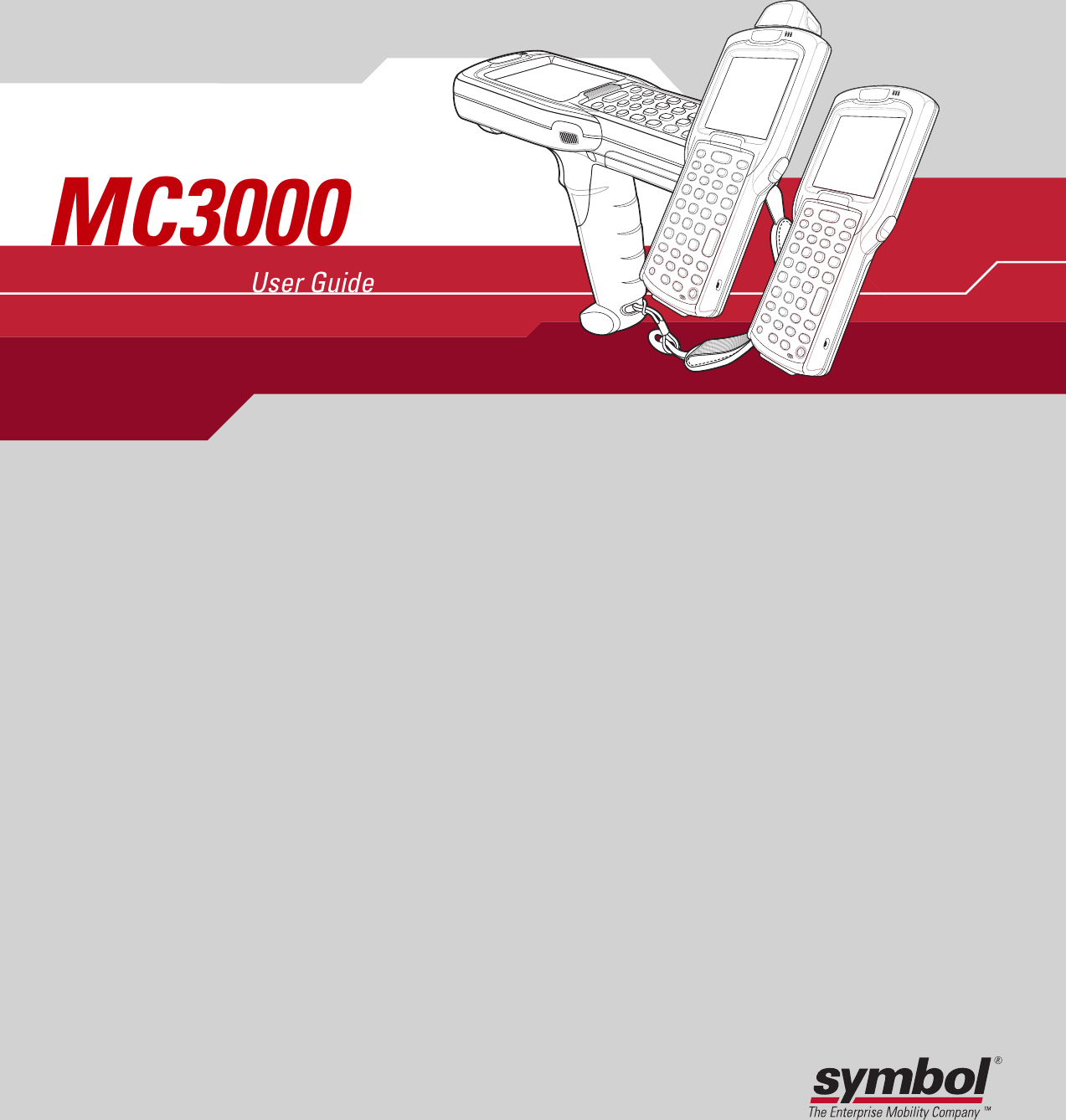
Symbol Technologies MC3090BT Handheld Wireless terminal User Manual MC3000 User Guide
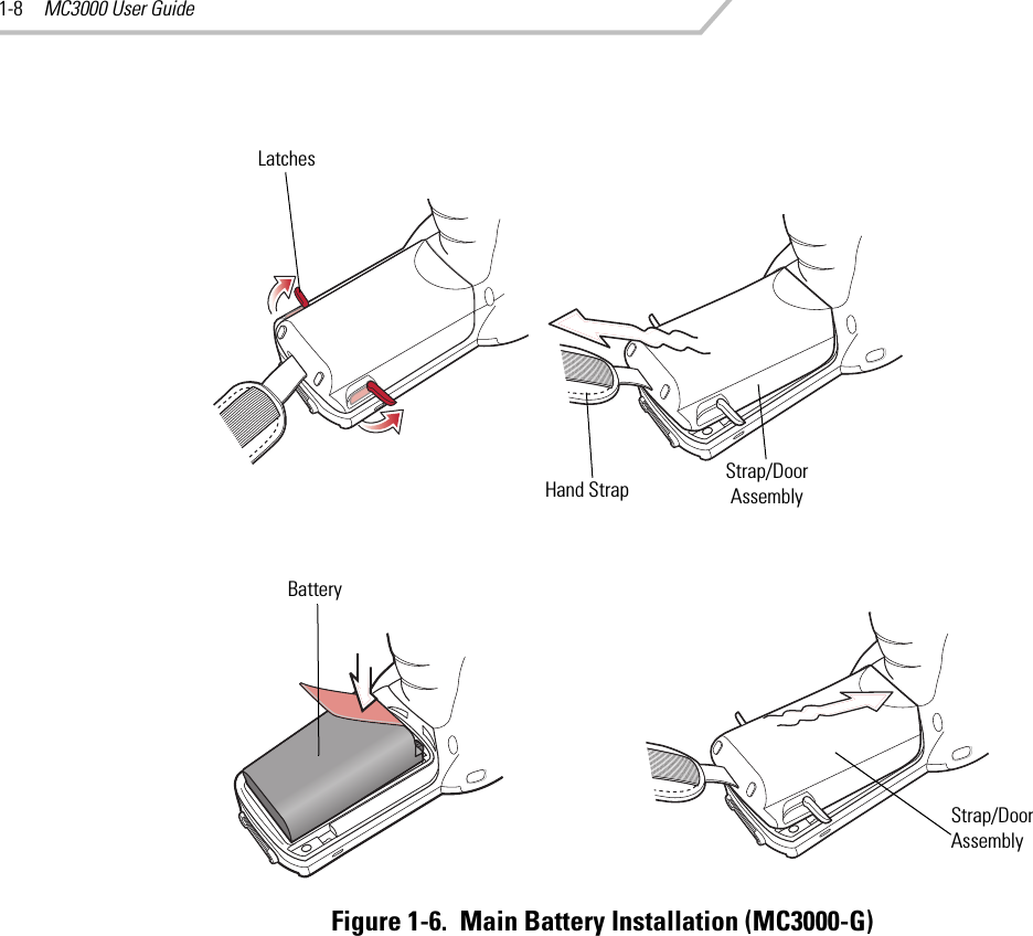
Symbol Technologies Inc Handheld Wireless terminal MC3000 User Guide
UserManual.wiki
>
Symbol Technologies
>
MC3090BT User Manual
>
Users Manual Part 1
Contents
1.
Users Manual Part 1
2.
Users Manual Part 2
3.
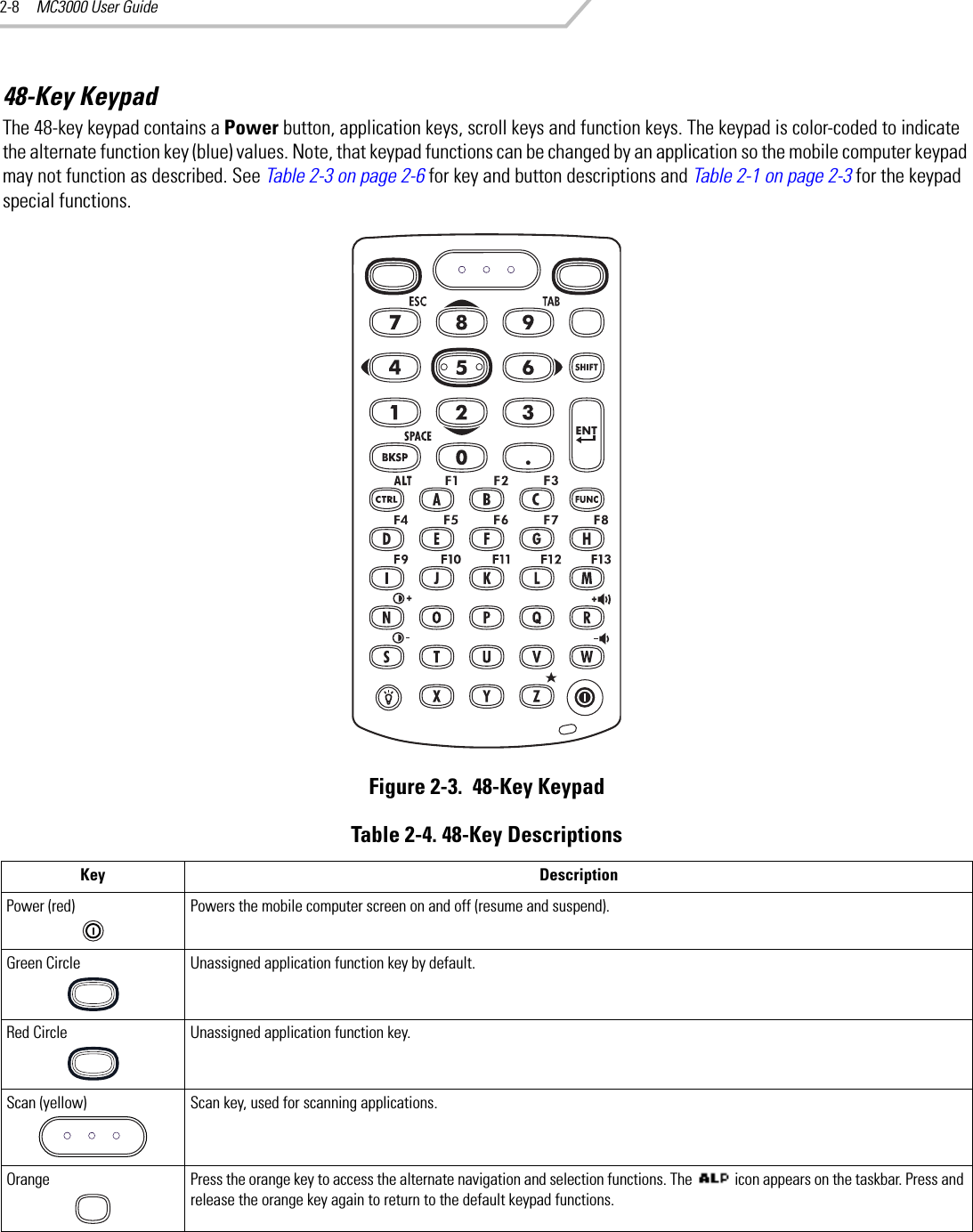
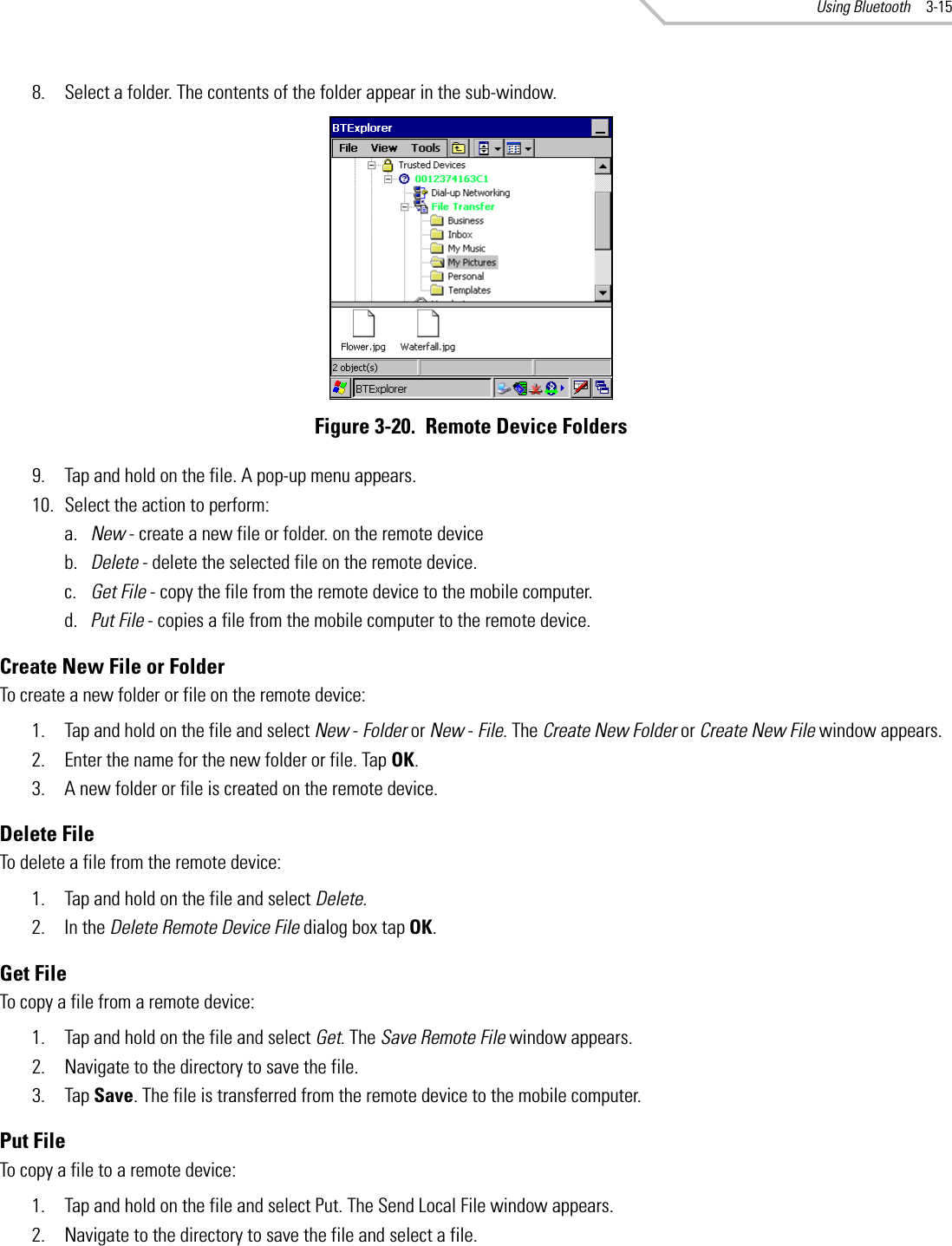
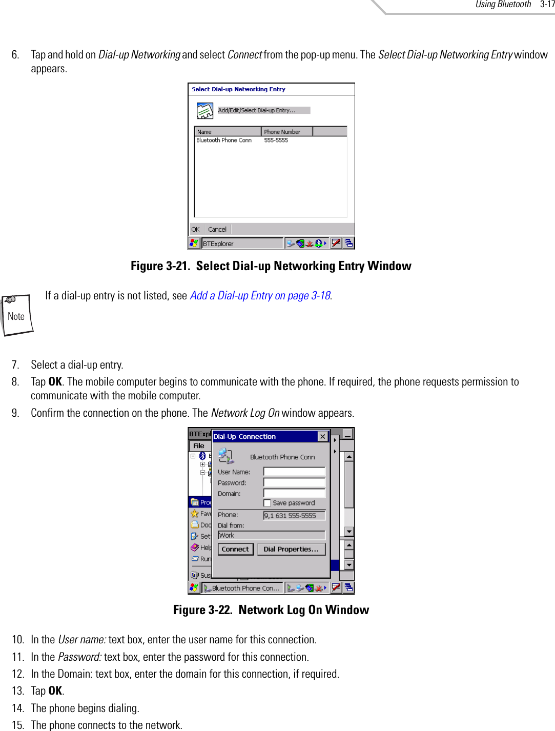
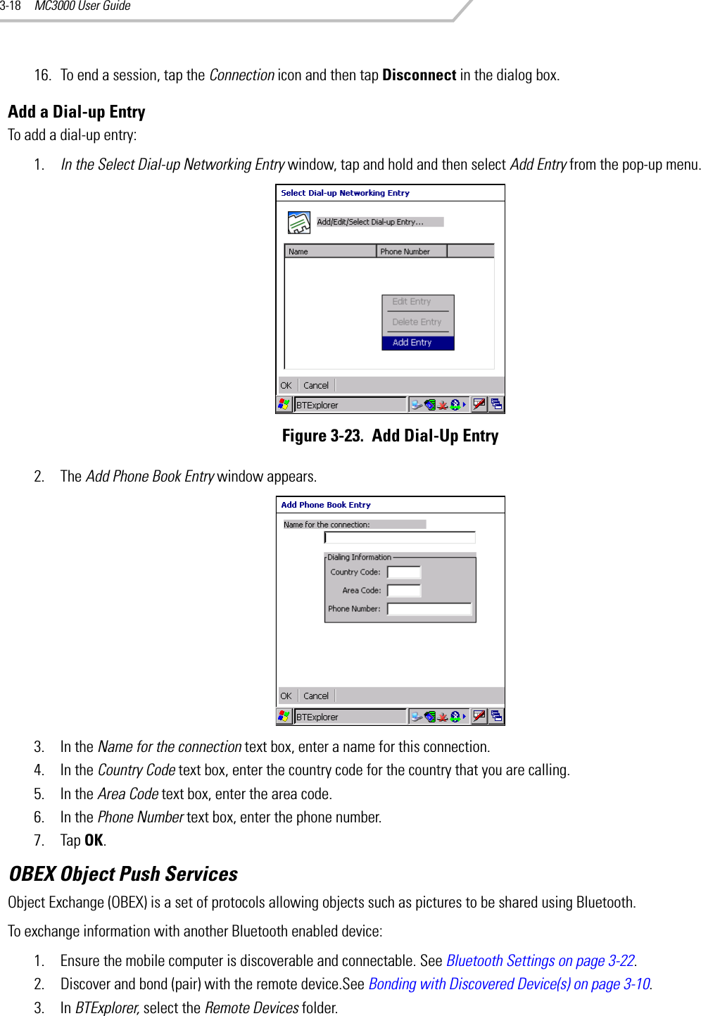
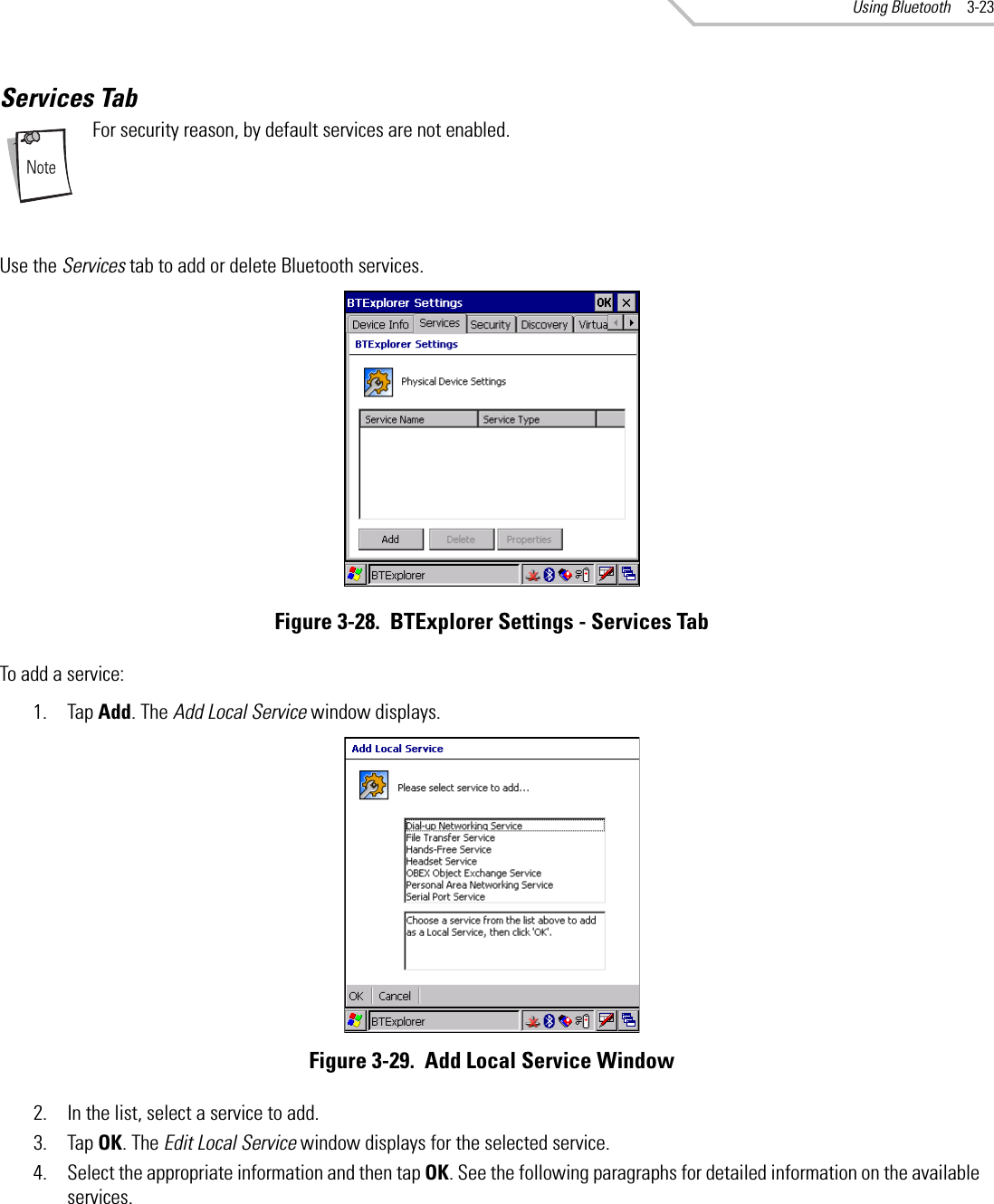
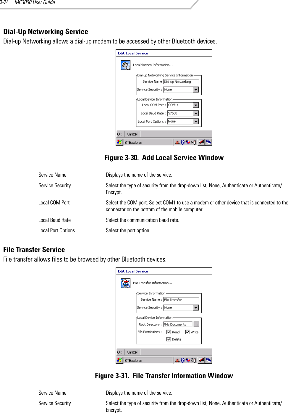
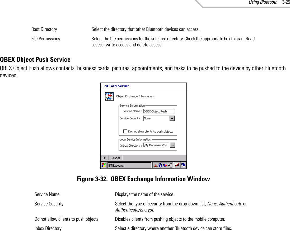
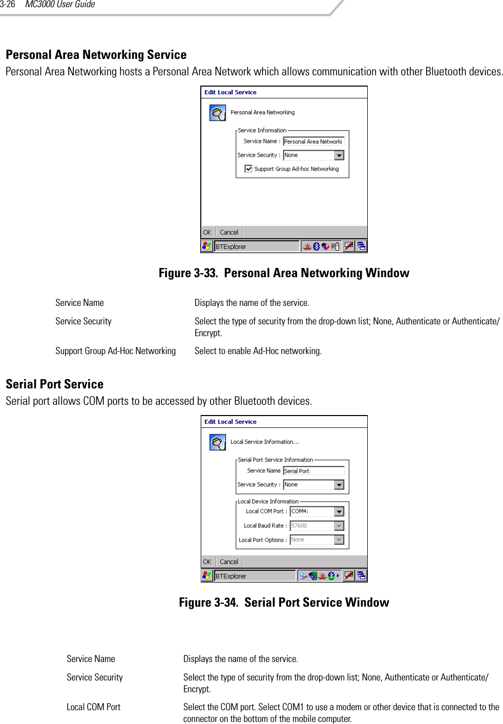
Users Manual
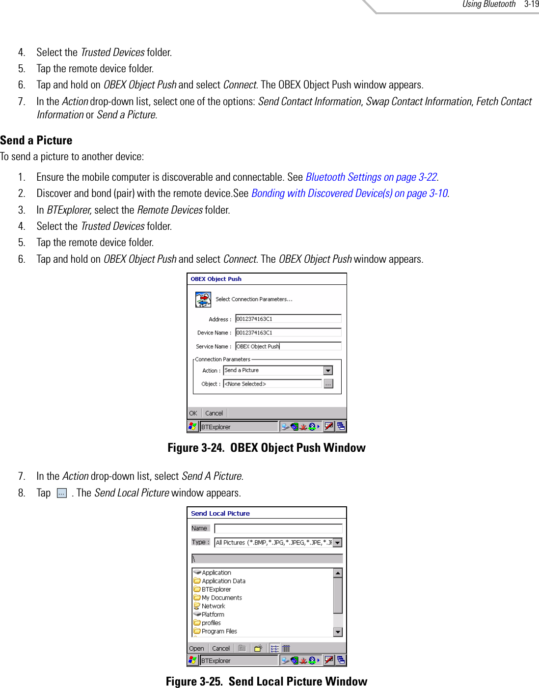
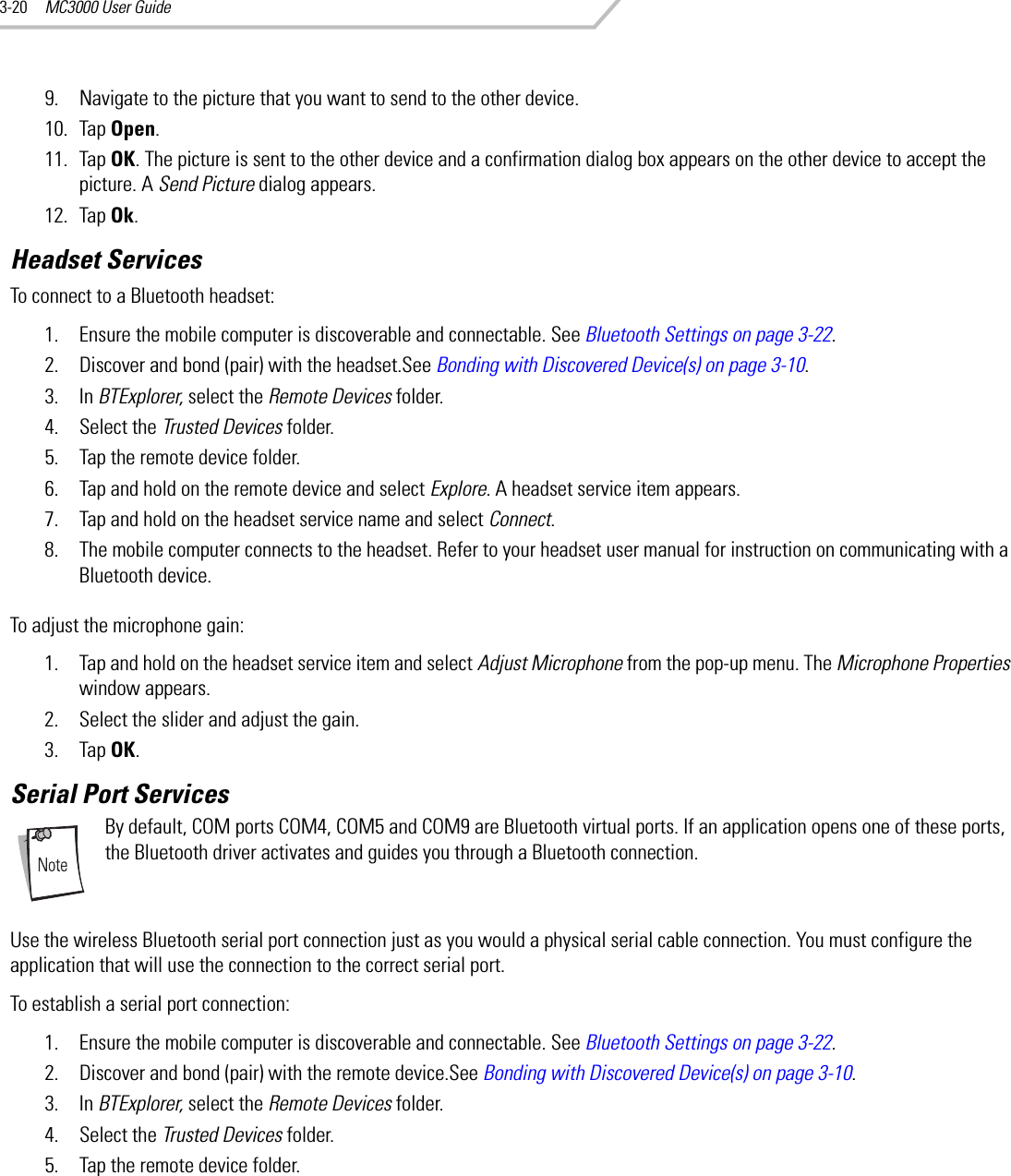
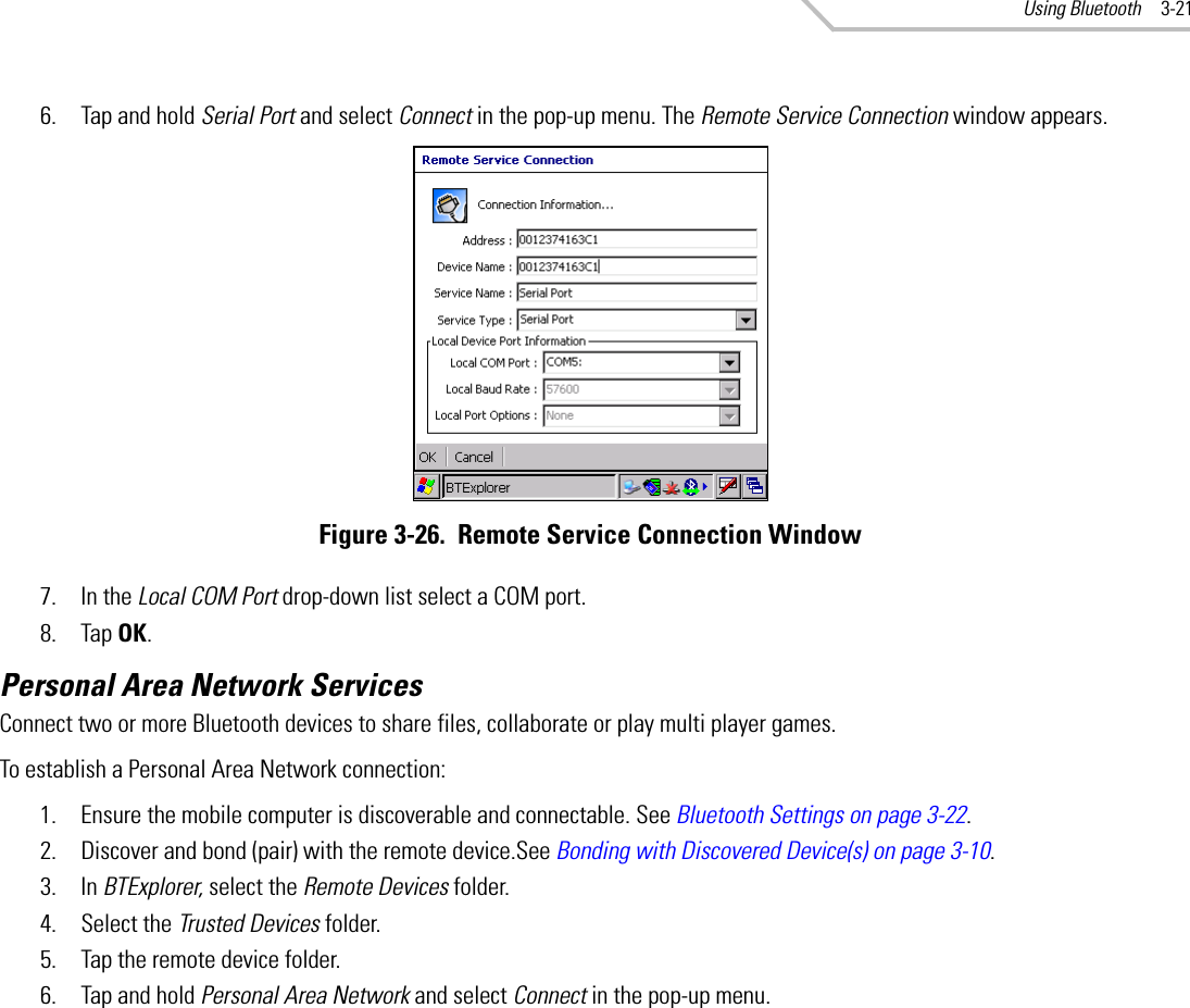
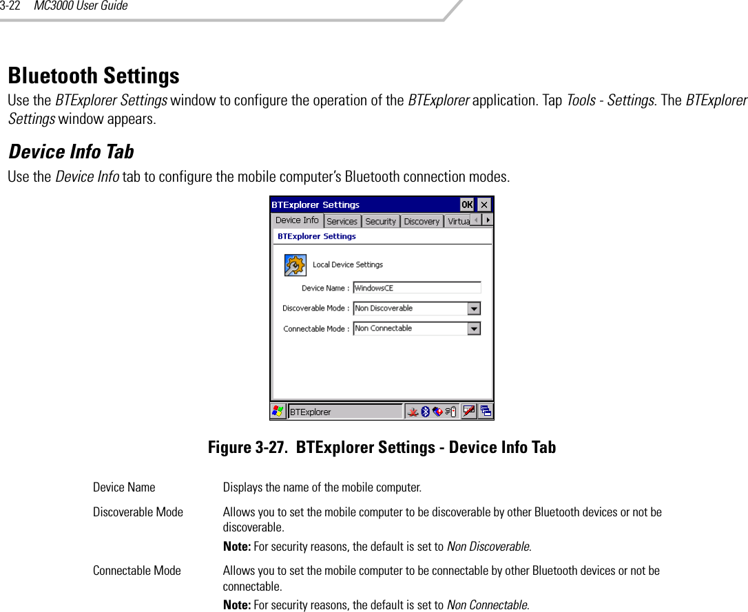
Users Manual Part 1
Navigation menu
Upload a User Manual
Namespaces
Wiki Guide
HTML
PDF
Info
Views
User Manual
Discussion / Help
Navigation