Symbol Technologies MC3090BT Handheld Wireless terminal User Manual MC3000 User Guide
Symbol Technologies Inc Handheld Wireless terminal MC3000 User Guide
Contents
- 1. Users Manual Part 1
- 2. Users Manual Part 2
- 3. Users Manual
Users Manual Part 2

Accessories
Chapter Contents
Introduction . . . . . . . . . . . . . . . . . . . . . . . . . . . . . . . . . . . . . . . . . . . . . . . . . . . . . . . . . . . . . . . . . . . . . . . . . . . . .4-3
Cradles . . . . . . . . . . . . . . . . . . . . . . . . . . . . . . . . . . . . . . . . . . . . . . . . . . . . . . . . . . . . . . . . . . . . . . . . . . . . .4-3
Spare Battery Chargers . . . . . . . . . . . . . . . . . . . . . . . . . . . . . . . . . . . . . . . . . . . . . . . . . . . . . . . . . . . . . . . .4-3
Cables. . . . . . . . . . . . . . . . . . . . . . . . . . . . . . . . . . . . . . . . . . . . . . . . . . . . . . . . . . . . . . . . . . . . . . . . . . . . . .4-3
SD Card. . . . . . . . . . . . . . . . . . . . . . . . . . . . . . . . . . . . . . . . . . . . . . . . . . . . . . . . . . . . . . . . . . . . . . . . . . . . .4-3
Plastic Holster . . . . . . . . . . . . . . . . . . . . . . . . . . . . . . . . . . . . . . . . . . . . . . . . . . . . . . . . . . . . . . . . . . . . . . .4-3
Fabric Holster . . . . . . . . . . . . . . . . . . . . . . . . . . . . . . . . . . . . . . . . . . . . . . . . . . . . . . . . . . . . . . . . . . . . . . . .4-3
Single Slot Serial/USB Cradle . . . . . . . . . . . . . . . . . . . . . . . . . . . . . . . . . . . . . . . . . . . . . . . . . . . . . . . . . . . . . . .4-4
Battery Charging. . . . . . . . . . . . . . . . . . . . . . . . . . . . . . . . . . . . . . . . . . . . . . . . . . . . . . . . . . . . . . . . . . . . . .4-4
Four Slot Cradles . . . . . . . . . . . . . . . . . . . . . . . . . . . . . . . . . . . . . . . . . . . . . . . . . . . . . . . . . . . . . . . . . . . . . . . . .4-6
Battery Charging. . . . . . . . . . . . . . . . . . . . . . . . . . . . . . . . . . . . . . . . . . . . . . . . . . . . . . . . . . . . . . . . . . . . . .4-6
LED Charge Indications . . . . . . . . . . . . . . . . . . . . . . . . . . . . . . . . . . . . . . . . . . . . . . . . . . . . . . . . . . . . . . . .4-7
Power LED . . . . . . . . . . . . . . . . . . . . . . . . . . . . . . . . . . . . . . . . . . . . . . . . . . . . . . . . . . . . . . . . . . . . . . . . . .4-7
Speed LED . . . . . . . . . . . . . . . . . . . . . . . . . . . . . . . . . . . . . . . . . . . . . . . . . . . . . . . . . . . . . . . . . . . . . . . . . .4-7
Link LED . . . . . . . . . . . . . . . . . . . . . . . . . . . . . . . . . . . . . . . . . . . . . . . . . . . . . . . . . . . . . . . . . . . . . . . . . . . .4-7
Four Slot Spare Battery Charger . . . . . . . . . . . . . . . . . . . . . . . . . . . . . . . . . . . . . . . . . . . . . . . . . . . . . . . . . . . . .4-8
Spare Battery Charging . . . . . . . . . . . . . . . . . . . . . . . . . . . . . . . . . . . . . . . . . . . . . . . . . . . . . . . . . . . . . . . .4-8
LED Charge Indications . . . . . . . . . . . . . . . . . . . . . . . . . . . . . . . . . . . . . . . . . . . . . . . . . . . . . . . . . . . . . . . .4-8
Cables. . . . . . . . . . . . . . . . . . . . . . . . . . . . . . . . . . . . . . . . . . . . . . . . . . . . . . . . . . . . . . . . . . . . . . . . . . . . . . . . . .4-9
Battery Charging and Operating Power . . . . . . . . . . . . . . . . . . . . . . . . . . . . . . . . . . . . . . . . . . . . . . . . . . .4-10
LED Charge Indications . . . . . . . . . . . . . . . . . . . . . . . . . . . . . . . . . . . . . . . . . . . . . . . . . . . . . . . . . . . . . . .4-10
Universal Battery Charger (UBC) Adapter . . . . . . . . . . . . . . . . . . . . . . . . . . . . . . . . . . . . . . . . . . . . . . . . . . . . .4-11
Spare Battery Charging . . . . . . . . . . . . . . . . . . . . . . . . . . . . . . . . . . . . . . . . . . . . . . . . . . . . . . . . . . . . . . .4-11
UBC Adapter LED Charge Indications . . . . . . . . . . . . . . . . . . . . . . . . . . . . . . . . . . . . . . . . . . . . . . . . . . . .4-12
Secure Device Card . . . . . . . . . . . . . . . . . . . . . . . . . . . . . . . . . . . . . . . . . . . . . . . . . . . . . . . . . . . . . . . . . . . . . .4-13

MC3000 User Guide4-2
Plastic Holster. . . . . . . . . . . . . . . . . . . . . . . . . . . . . . . . . . . . . . . . . . . . . . . . . . . . . . . . . . . . . . . . . . . . . . . . . . .4-14
Fabric Holster . . . . . . . . . . . . . . . . . . . . . . . . . . . . . . . . . . . . . . . . . . . . . . . . . . . . . . . . . . . . . . . . . . . . . . . . . . .4-16
Belt Clip . . . . . . . . . . . . . . . . . . . . . . . . . . . . . . . . . . . . . . . . . . . . . . . . . . . . . . . . . . . . . . . . . . . . . . .4-16
Shoulder Strap . . . . . . . . . . . . . . . . . . . . . . . . . . . . . . . . . . . . . . . . . . . . . . . . . . . . . . . . . . . . . . . . . .4-17

Accessories 4-3
Introduction
The MC3000 accessories provide a variety of product support capabilities. Accessories include cradles, cables, spare battery chargers
and SD cards.
Cradles
• The Single Slot Serial/USB cradle charges the mobile computer main battery and/or a spare battery. It also synchronizes the
mobile computer with a host computer through either a serial or a USB connection.
• The Four Slot Charge Only cradle charges up to four mobile computers.
• The Four Slot Ethernet cradle charges up to four mobile computers and provides Ethernet communication.
Spare Battery Chargers
• Four Slot Spare Battery Charger charges up to four MC3000 spare batteries.
• UBC Adapter adapts the UBC2000 for use with the MC3000 batteries.
The accessory power supply regulatory compliance statements are provided in Table C-1 on page C-3.
Cables
The cables snap on to the mobile computer and are used to connect external devices to the mobile computer.
• USB client charge cable
• RS232 Charge cable
• O’Neil printer cable
• Zebra printer cable
• Monarch printer cable.
SD Card
The SD card provides additional storage capacity for the mobile computer.
Plastic Holster
The Plastic Holster provides a clip on holder for the mobile computer.
Fabric Holster
The Fabric Holster provides a clip on holder for the mobile computer.
MC3000 User Guide4-4
Single Slot Serial/USB Cradle
The Single Slot Serial/USB cradle:
• Provides 5.4VDC power for operating the mobile computer, charging the battery and charging a spare battery.
• Provides a serial port and a USB port for data communication between the mobile computer and a host computer or other
serial devices (e.g., a printer).
• Synchronizes information between the mobile computer and a host computer. With customized or third party software, it can
also synchronize the mobile computer with corporate databases.
• Provides serial connection through the serial pass-through port for communication with a serial device, such as a host
computer. For communication setup procedures, refer to the MC3000 Integrator Guide.
• Provides USB connection through the USB pass-through port for communication with a USB device, such as a host computer.
For communication setup procedures, refer to the MC3000 Integrator Guide.
Use only a Symbol approved power supply output rated 12 VDC and minimum 3.3 A. Use of an alternative
power supply will void the product warranty and may cause product damage. See Appendix C, Regulatory for
the power supply regulatory compliance statement.
Battery Charging
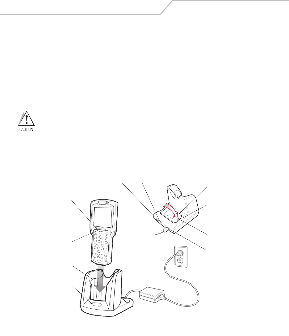
The Single Slot Serial/USB cradle can charge the mobile computer main battery and a spare battery simultaneously.
To charge the mobile computer:
1. Slide the mobile computer into the mobile computer slot. The mobile computer amber Charge LED Indicator, indicates the
mobile computer battery charging status. The Standard Battery charges in less than four hours and the Extended Life Battery
charges in less than six hours. See Table 4-1 for charging status indications.
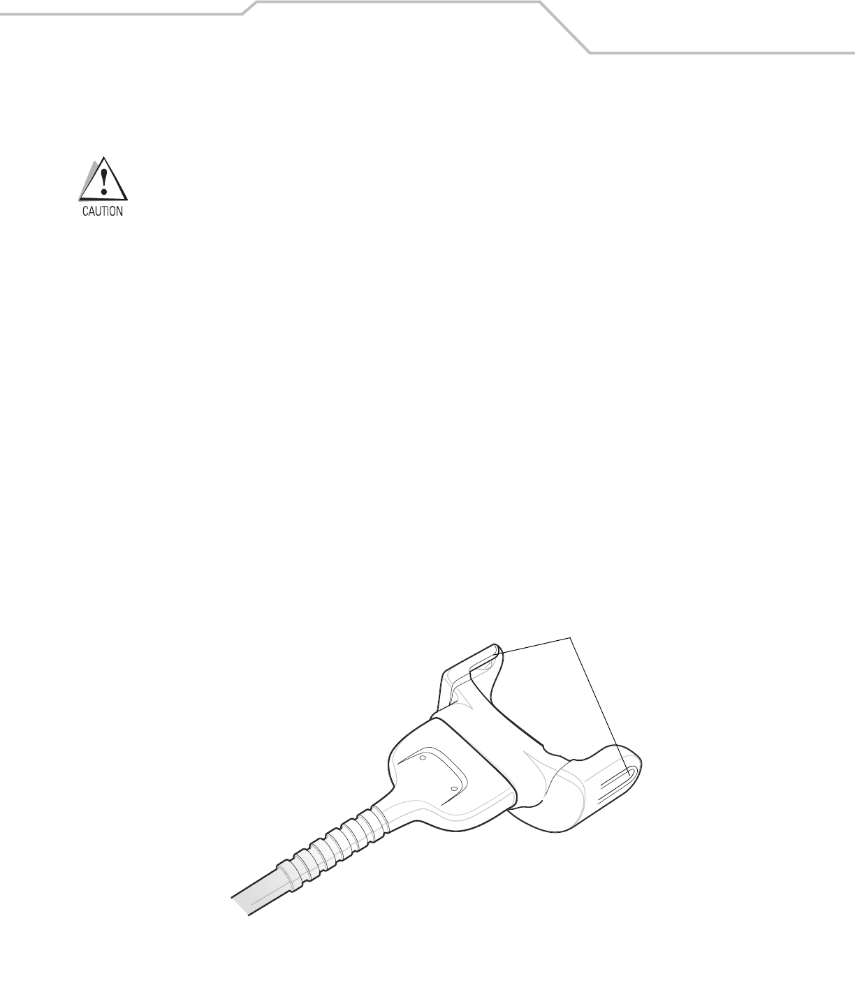
Figure 4-1. Single Slot Serial/USB Cradle
2. When charging is complete, remove the mobile computer from the mobile computer slot.
Indicator
LED Bar
Mobile
Computer Slot
Spare
Battery
Spare
Battery
Charging
LED
Power Port
Serial Port
USB Port
Spare
Battery
Charging
Slot
Battery
Clip
Charge LED
Indicator
(amber)
Accessories 4-5
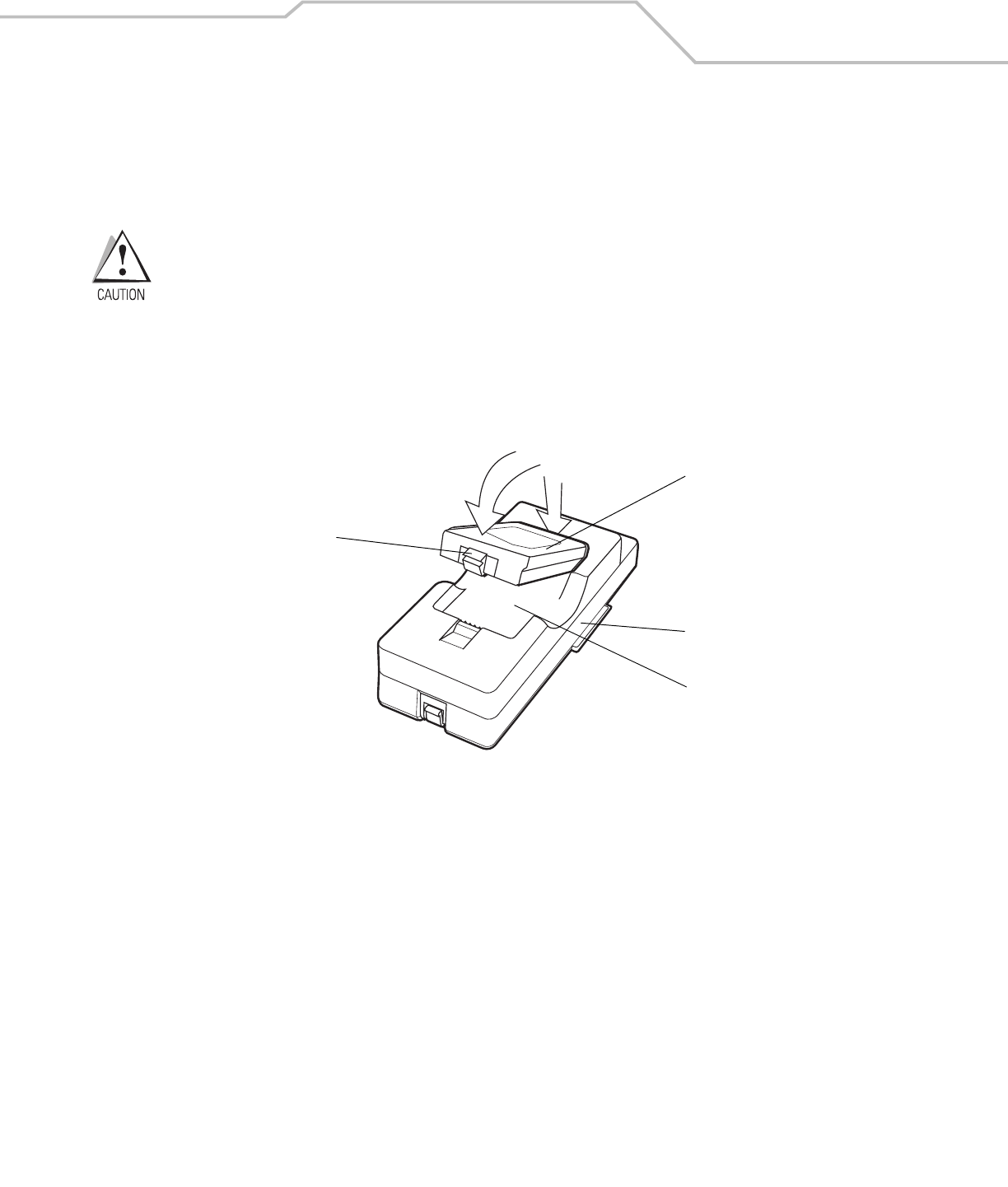
To charge the spare battery:
1. Insert the spare battery into the spare battery charging slot, bottom first, and pivot the top of the battery down onto the
contact pins.
2. Gently press down on the battery to ensure proper contact.
3. The Spare Battery Charging LED (see Figure 4-1 on page 4-4) indicates the spare battery charging status. The
Standard Battery charges in less than four hours and the Extended Life Battery charges in less than six hours. See
Table 4-1 for charging status indications.
4. When charging is complete, press the battery clip and lift the battery out of the slot.
LED Charge Indications
The Single Slot Serial/USB cradle uses the mobile computer amber Charge LED Indicator to indicate the battery charging status and
the Spare Battery Charging LED to indicate spare battery charging status. See Table 4-1 for charging status indications.
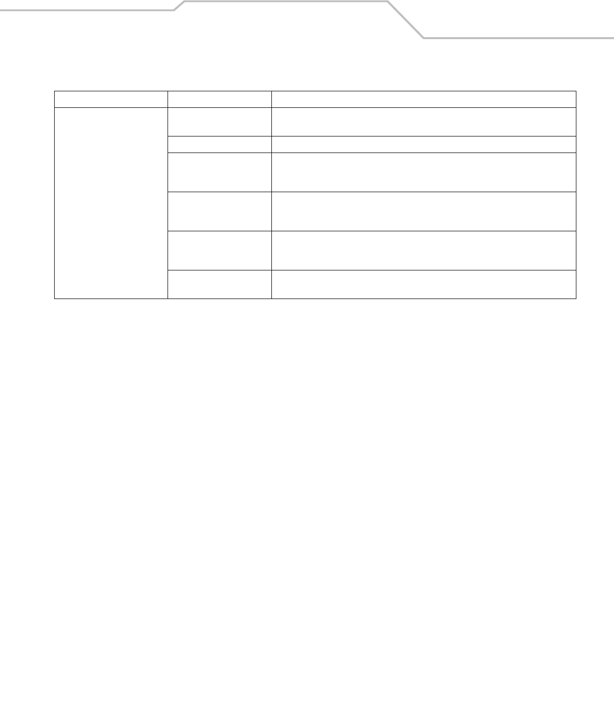
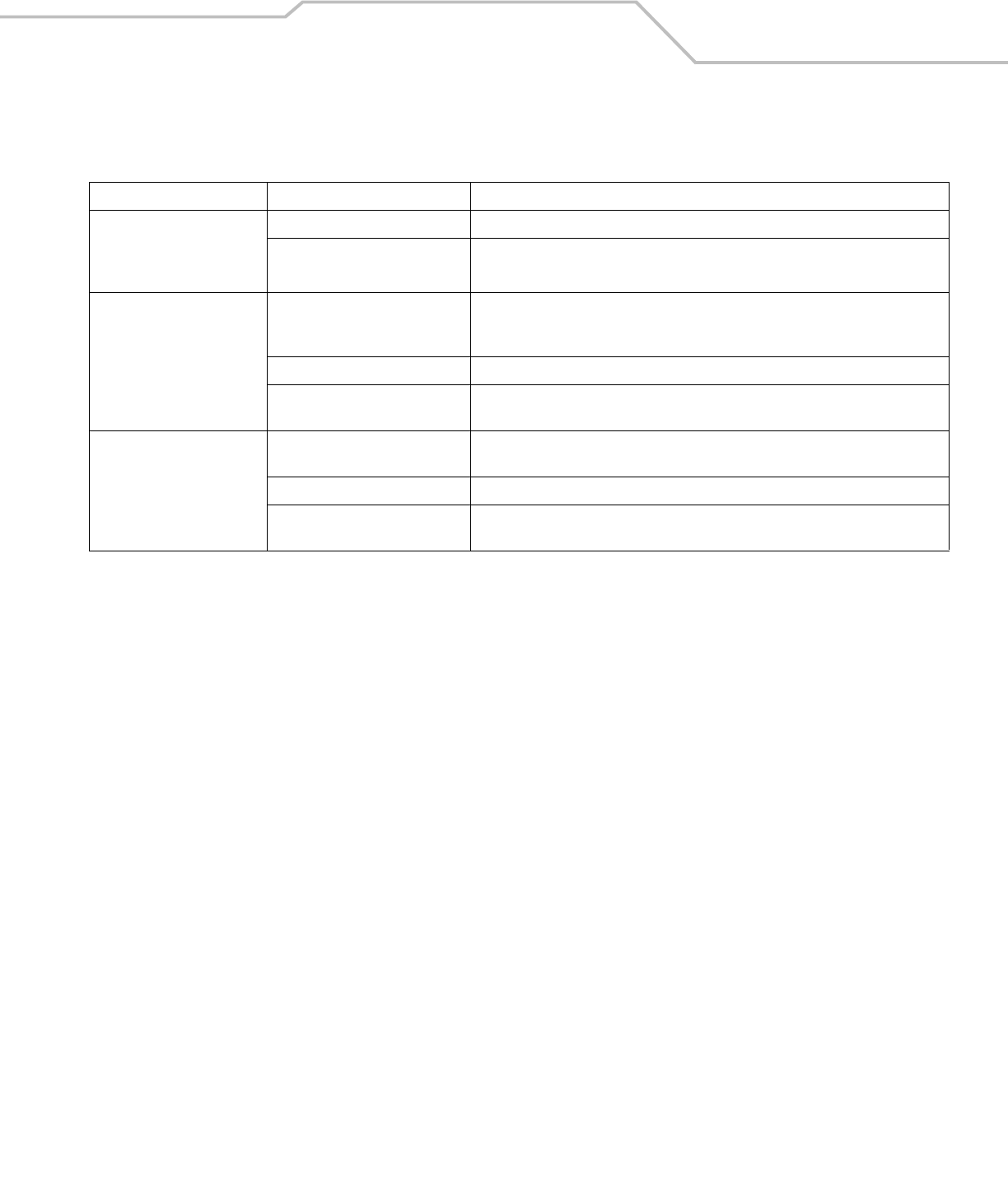
Table 4-1. LED Charging Status Indicators
LED Indication
Mobile Computer Charging (LED on mobile computer)
Off Mobile computer not placed correctly in the cradle; cable not connected correctly; charger is not powered.
Fast Blinking Amber Error in charging; check placement of mobile computer.
Slow Blinking Amber Mobile computer is charging.
Solid Amber Charging complete.
Note: When the battery is initially inserted in the mobile computer, the amber LED flashes once if the battery
power is low or the battery is not fully inserted.
Spare Battery Charging (LED on cradle)
Off No spare battery in slot; spare battery not placed correctly; cradle is not powered.
Fast Blinking Amber Error in charging; check placement of spare battery.
Slow Blinking Amber Spare battery is charging.
Solid Amber Charging complete.
MC3000 User Guide4-6
Four Slot Cradles
There are two four slot cradles, Four Slot Charge Only cradle and Four Slot Ethernet cradle. The Four Slot Ethernet cradle provides
Ethernet communications. Both four slot cradles:
• Provide 5.4 VDC power for operating the mobile computer and charging the battery.
• Simultaneously charges up to four mobile computers.
Use only a Symbol approved power supply output rated 12 VDC and minimum 9 A. Use of an alternative power
supply will void the product warranty and may cause product damage. See Appendix C, Regulatory for the
power supply regulatory compliance statement.
Battery Charging
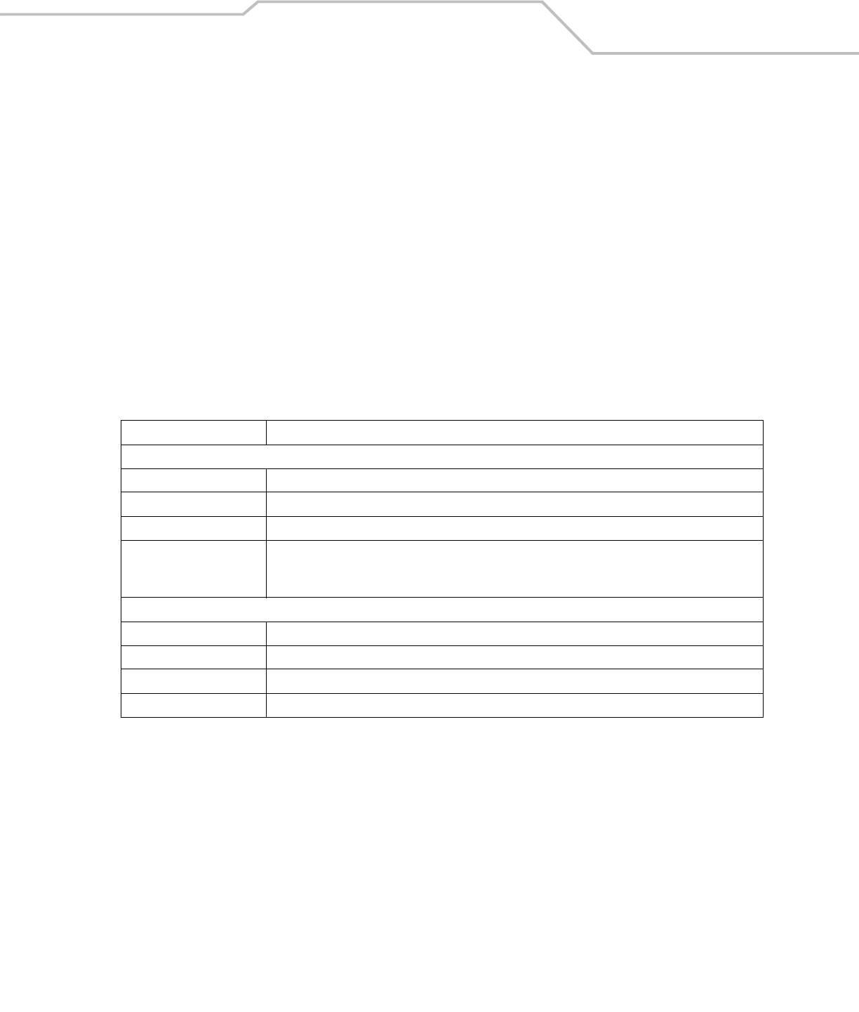
The four slot cradle can charge up to four mobile computers simultaneously. To charge the mobile computer:
1. Slide the mobile computer into the mobile computer slot.
Figure 4-2. Four Slot Cradles
2. The mobile computer amber Charge LED Indicator, indicates the mobile computer battery charging status. The Standard
Battery usually charges in less than four hours and the Extended Life Battery usually charges in less than six hours. See Table
4-1 for charging status indications.
3. When charging is complete, remove the mobile computer from the cradle.
Scan/Charge Indicator LED Bar
Mobile Computer Slot
Charge LED Indicator (amber)
Speed LED (Ethernet Cradle Only)
Link LED (Ethernet Cradle Only)
Power LED (Charge Only Cradle)

Accessories 4-7
LED Charge Indications
The Four Slot cradles use the mobile computer amber Charge LED Indicator to indicate the battery charging status. See Table
4-1 on page 4-5 for charging status indications.
Power LED
The green Power LED (only on the Four Slot Charge Only cradle) lights to indicate that the Four Slot Charge Only cradle is connected
to a power source.
Speed LED
The green Speed LED (only on the Four Slot Ethernet cradle) lights to indicate that the transfer rate is 100 Mbps. When it is not lit it
indicates that the transfer rate is 10 Mbps.
Link LED
The yellow Link LED (only on the Four Slot Ethernet cradle) blinks to indicate activity, or stays lit to indicate that a link is established.
When it is not lit, it indicates that there is no link.
MC3000 User Guide4-8
Four Slot Spare Battery Charger
The Four Slot Spare Battery Charger simultaneously charges up to four spare batteries.
Use only a Symbol approved power supply output rated 12 VDC and minimum 3.3 A. Use of an alternative
power supply will void the product warranty and may cause product damage. See Appendix C, Regulatory for
the power supply regulatory compliance statement.
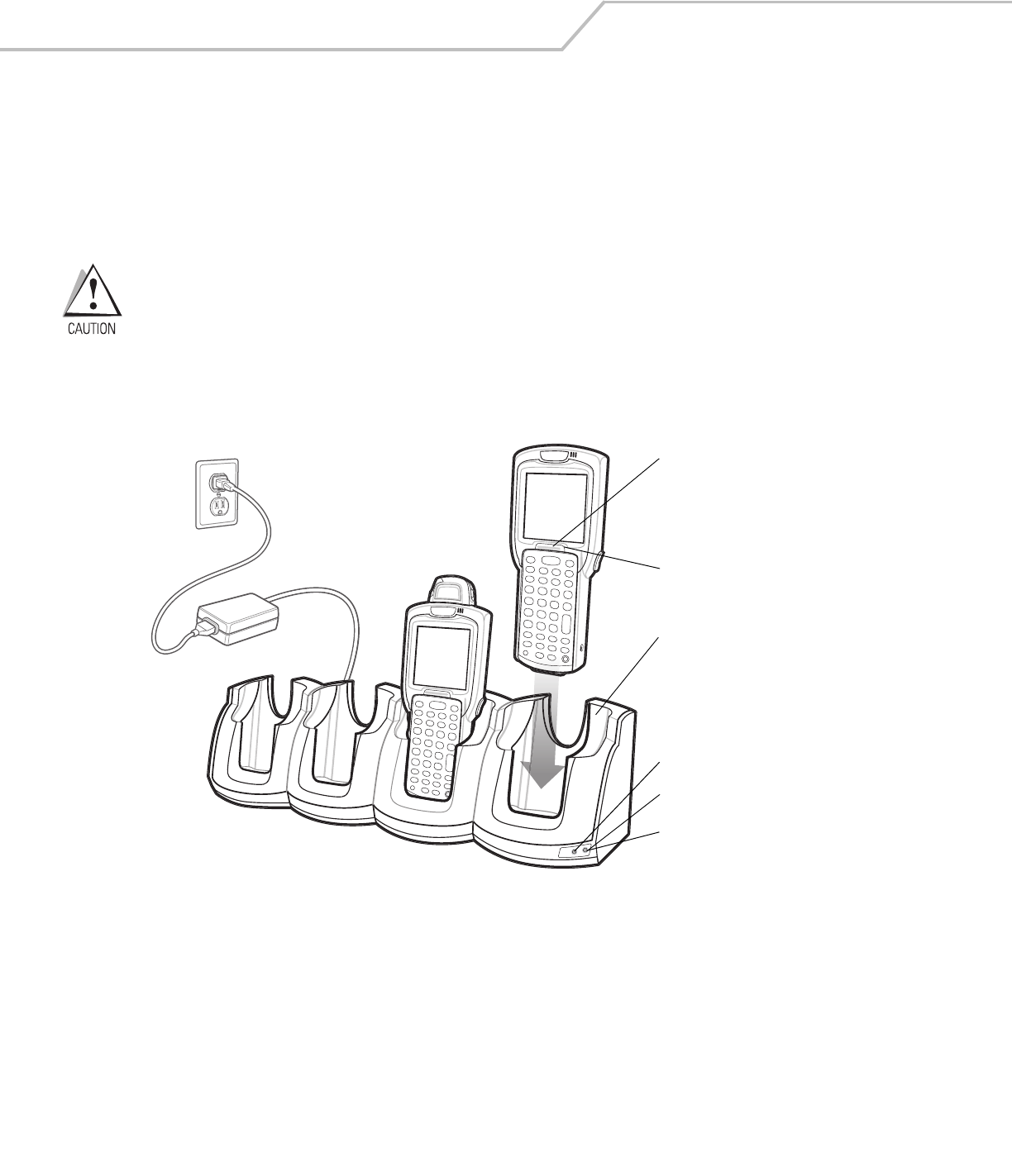
Spare Battery Charging
To charge up to four MC3000 spare batteries:
1. Insert the spare battery into the spare battery charging slot, bottom first.
2. Pivot the top of the battery down onto the contact pins.
Figure 4-3. Four Slot Spare Battery Charger
3. Gently press down on the battery to ensure proper contact. The Standard Battery usually charges in less than four hours and
the Extended Life Battery usually charges in less than six hours. See Table 4-1 on page 4-5 for charging status indications.
4. When charging is complete, press the battery clip and lift battery out of the slot.
LED Charge Indications
The Spare Battery Charging LEDs indicate the spare battery charging status. The Spare Battery Charging LEDs are arranged in the
same pattern as the spare battery charging slots so that the charging status of each battery can be identified. See Table 4-1 on page
4-5 for charging status indications.
Power Supply
Spare
Batteries
Spare
Battery
Charging
Slot
Spare Battery
Charging LEDs (4)
Battery
Clip
1
2
Accessories 4-9
Cables
The cables are available with a variety of connection capabilities.
Use only a Symbol approved power supply output rated 5.4 VDC and minimum 3 A. Use of an alternative power
supply will void the product warranty and may cause product damage. See Appendix C, Regulatory for the
power supply regulatory compliance statement.
MC3000 Communication/Charge cables:
• Provide the mobile computer with operating and charging power when used with the Symbol approved power supply.
• Synchronize information between the mobile computer and a host computer. With customized or third party software, it can
also synchronize the mobile computer with corporate databases.
• Provide serial connection through the serial pass-through port for communication with a serial device, such as a host
computer. For communication setup procedures, refer to the MC3000 Integrator Guide.
• Provide USB connection through the USB pass-through port for communication with a USB device, such as a host computer.
For communication setup procedures, refer to the MC3000 Integrator Guide.
The following MC3000 Communication/Charge cables are available:
• Serial (RS232) Charge cable (9-pin D female with power input receptacle)
• USB Client Charge cable (standard-A connector and a barrel receptacle for power).
Dedicated Printer cables, provide communication with a dedicated printer.
The following printer cables are available directly from the printer manufacturer:
• O’Neil printer cable
• Zebra printer cable
• Monarch printer cable.
Figure 4-4. Cables
Snaps

MC3000 User Guide4-10
Battery Charging and Operating Power
The MC3000 Communication/Charge cables can charge the mobile computer battery and supply operating power.
To charge the mobile computer battery:
1. Connect the MC3000 Communication/Charge cable power input connector to the Symbol approved power source.
2. Slide the bottom of the mobile computer into the MC3000 connector end of the MC3000 Communication/Charge cable and
gently press in until the snaps latch into the mobile computer.
3. The mobile computer amber Charge LED Indicator indicates the mobile computer battery charging status. The Standard
Battery usually charges in less than four hours and the Extended Life Battery usually charges in less than six hours. See,
Table 4-1 on page 4-5 for charging status indications.
4. When charging is complete, remove the cable by gently pulling the mobile computer and the cable apart until the snaps
release the mobile computer.
LED Charge Indications
The MC3000 Communication/Charge cables use the amber Charge LED Indicator to indicate the MC3000 battery charging status. See,
Table 4-1 on page 4-5 for charging status indications.
Accessories 4-11
Universal Battery Charger (UBC) Adapter
The UBC Adapter can be used with a power supply as a standalone spare battery charger or it can be used with the four station
UBC2000 to simultaneously charge up to four spare batteries. For additional information on the UBC 2000, refer to the UBC 2000 Quick
Reference Guide p/n 70-33188-xx.
Use only a Symbol approved power supply output rated 15 VDC and minimum 1.5 A. Use of an alternative
power supply will void the product warranty and may cause product damage. See Appendix C, Regulatory for
the power supply regulatory compliance statement.
Spare Battery Charging
To charge spare batteries:
1. Insert the spare battery into the spare battery charging slot, bottom first.
2. Pivot the top of the battery down onto the contact pins.
Figure 4-5. UBC Adapter Battery Insertion
3. Gently press down on the battery to ensure proper contact. The Standard Battery usually charges in less than four hours and
the Extended Life Battery usually charges in less than six hours. See, Table 4-2 on page 4-12 for charging status indications.
4. When charging is complete, press the battery clip and lift the battery out of the slot.
UBC Adapter
Battery
Battery Clip
Spare Battery
Charging Slot
2
1
MC3000 User Guide4-12
UBC Adapter LED Charge Indications
The UBC Adapter charging LEDs indicate the battery charging status. The Standard Battery usually charges in less than four hours
and the Extended Life Battery usually charges in less than six hours.
Figure 4-6. UBC Adapter LEDs
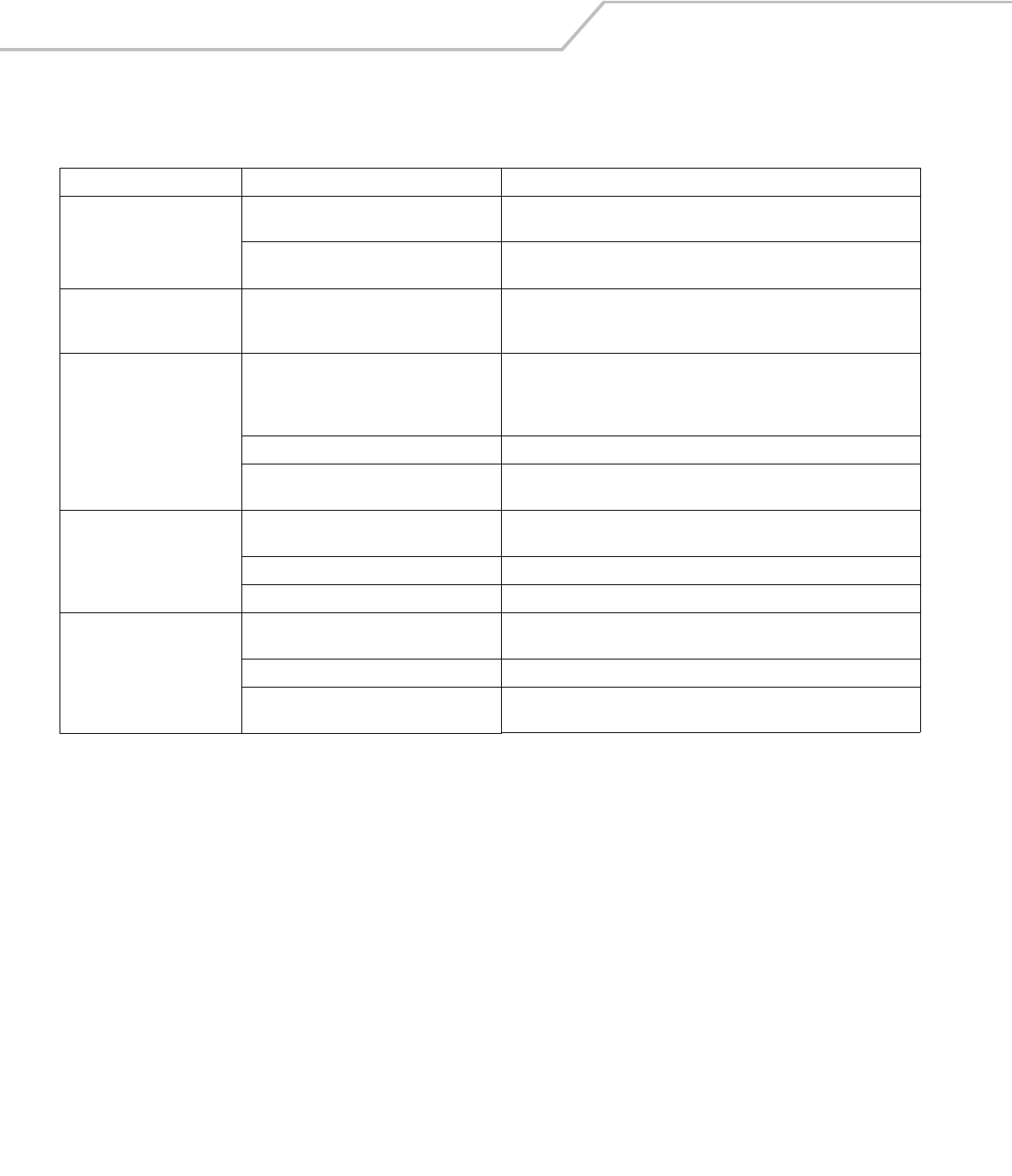
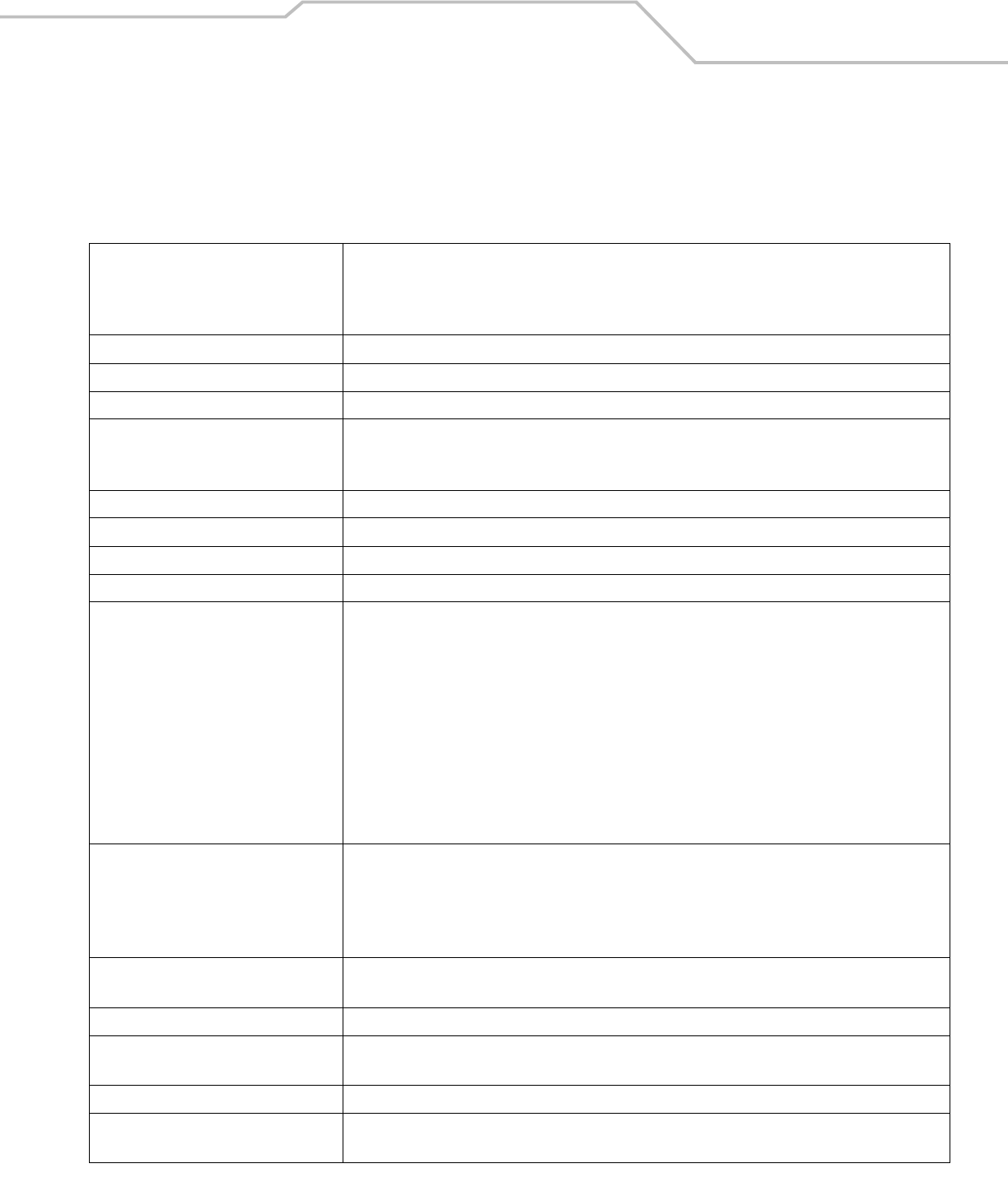
Table 4-2. UBC Adapter Charge LED Status Indications
LED Indication Description
POWER Green Power is connected to the UBC Adapter.
READY or Green Charging complete.
STANDBY or Flashing-
Yellow
The battery was deeply discharged and is being trickle charged to bring the voltage up to the
operating level. After operating level voltage is achieved, the battery charges normally.
FAULT Yellow Charging error, check placement of mobile computer/spare battery.
CHARGING Yellow Normal charge.
POWER
READY or STANDBY or FAULT
CHARGING
(Green) (Flashing Yellow) (Solid Yellow)
(Solid Yellow)
Accessories 4-13
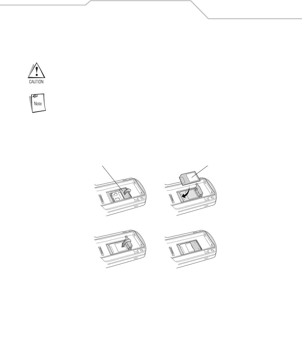
Secure Device Card
The Secure Device (SD) card provides secondary non-volatile storage (the flash memory is slower than RAM). The SD card holder is
located under the battery.
Follow proper Electro-Static Discharge (ESD) precautions to avoid damaging the SD card. Proper ESD
precautions include, but are not limited to, working on an ESD mat and ensuring that the operator is properly
grounded.
Do not use the SD card slot for any other accessories.
Select SD cards with environmental and/or the write cycle performance specifications that meet or exceed
the application requirements.
To insert the SD card:
1. Remove the battery (see Main Battery Removal on page 1-12).
2. Lift the SD card retaining door.
3. Position the SD card, with the contacts down, into the SD card slot. The SD card corner notch fits into the slot only one way.
4. Close SD card retaining door.
Figure 4-7. Inserting the SD Card
5. Replace the battery (see Install Main Battery on page 1-6).
SD Card Retaining Door SD Card
MC3000 User Guide4-14
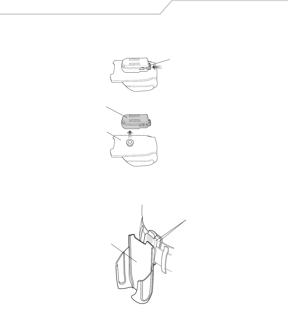
Plastic Holster
The Plastic Holster provides a holder for the mobile computer. It consists of a mobile computer holder and a detachable belt clip. Press
the release button to remove the detachable belt clip.
Figure 4-8. Plastic Holster
Pinch the clip release and attach the Plastic Holster to a belt or waist band.
Figure 4-9. Attaching the Plastic Holster
The Plastic Holster holds the mobile computer on a belt or waist band.
Detachable Belt Clip
Release Button
Mobile Computer Holder
Clip Release
Mobile Computer Holder
Accessories 4-15
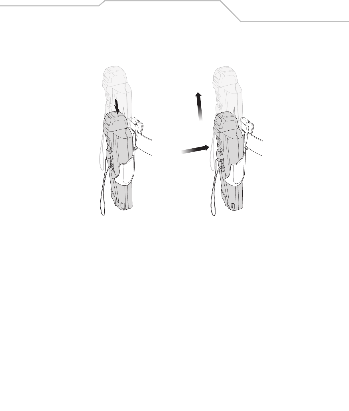
To insert the mobile computer, slide the mobile computer into the Plastic Holster with the screen facing the user.
To remove the mobile computer, press and lift to remove the mobile computer.
Figure 4-10. Insert and Remove the Mobile Computer
Insert Mobile Computer Remove Mobile Computer
MC3000 User Guide4-16
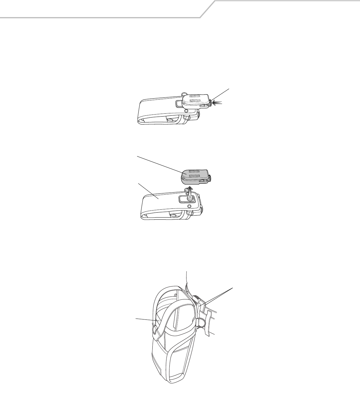
Fabric Holster
The Fabric Holster provides a soft holder for the mobile computer. It consists of a fabric mobile computer holder, a detachable shoulder
strap and a detachable belt clip. Press the release button to remove the detachable belt clip. See Figure 4-11 to remove the detachable
clip see Figure 4-12 on page 4-16 to attach the Fabric Holster to a belt and see Figure 4-13 on page 4-17 to attach the Fabric Holster
to a shoulder strap. See The Plastic Holster holds the mobile computer on a belt or waist band. on page 4-14 for instructions on
inserting and removing the mobile computer.
Figure 4-11. Fabric Holster Detachable Belt Clip
Belt Clip
Pinch the clip release and attach the Fabric Holster to a belt or waist band.
Figure 4-12. Attaching the Fabric Holster To a Belt
Detachable Belt Clip
Release Button
Mobile Computer Holder
Clip Release
Mobile Computer Holder
Accessories 4-17
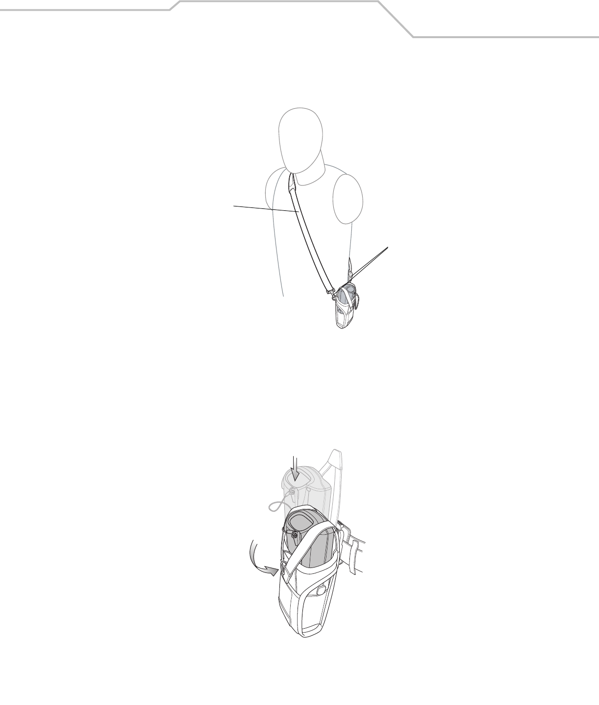
Shoulder Strap
Remove the detachable belt clip (see Figure 4-11 on page 4-16) and attach the shoulder strap.
Figure 4-13. Attach the Fabric Holster To the Shoulder Strap
The Fabric Holster holds the mobile computer on a belt or waist band.
1. To insert the mobile computer, slide the mobile computer into the Fabric Holster with the screen facing the user.
2. Pull restraining strap over mobile computer and secure in the clip.
3. To remove the mobile computer, pull down on restraining strap to release from clip and lift retaining strap clear.
4. Lift mobile computer out of Fabric Holster.
Figure 4-14. Insert and Remove the Mobile Computer
Clip Release
Shoulder Strap

MC3000 User Guide4-18

Maintenance & Troubleshooting
Introduction . . . . . . . . . . . . . . . . . . . . . . . . . . . . . . . . . . . . . . . . . . . . . . . . . . . . . . . . . . . . . . . . . . . . . . . . . . . . 5- 3
Maintaining the Mobile Computer. . . . . . . . . . . . . . . . . . . . . . . . . . . . . . . . . . . . . . . . . . . . . . . . . . . . . . . . . . . .5-3
Troubleshooting . . . . . . . . . . . . . . . . . . . . . . . . . . . . . . . . . . . . . . . . . . . . . . . . . . . . . . . . . . . . . . . . . . . . . . . . . .5-4
Mobile Computer . . . . . . . . . . . . . . . . . . . . . . . . . . . . . . . . . . . . . . . . . . . . . . . . . . . . . . . . . . . . . . . . . . . . .5-4
Single Slot Serial/USB Cradle . . . . . . . . . . . . . . . . . . . . . . . . . . . . . . . . . . . . . . . . . . . . . . . . . . . . . . . . . . .5-6
Four Slot Charge Only Cradle. . . . . . . . . . . . . . . . . . . . . . . . . . . . . . . . . . . . . . . . . . . . . . . . . . . . . . . . . . . .5-7
Four Slot Ethernet Cradle. . . . . . . . . . . . . . . . . . . . . . . . . . . . . . . . . . . . . . . . . . . . . . . . . . . . . . . . . . . . . . .5-7
Four Slot Spare Battery Charger . . . . . . . . . . . . . . . . . . . . . . . . . . . . . . . . . . . . . . . . . . . . . . . . . . . . . . . . .5-8
UBC Adapter. . . . . . . . . . . . . . . . . . . . . . . . . . . . . . . . . . . . . . . . . . . . . . . . . . . . . . . . . . . . . . . . . . . . . . . . .5-8
Cables. . . . . . . . . . . . . . . . . . . . . . . . . . . . . . . . . . . . . . . . . . . . . . . . . . . . . . . . . . . . . . . . . . . . . . . . . . . . . .5-9

MC3000 User Guide5-2

Maintenance & Troubleshooting 5-3
Introduction
This chapter includes instructions on cleaning and storing the mobile computer, and provides troubleshooting solutions for potential
problems during mobile computer operation.
Maintaining the Mobile Computer
For trouble-free service, observe the following tips when using the mobile computer:
• Do not scratch the screen of the mobile computer. When working with the mobile computer, use the supplied stylus or
plastic-tipped pens intended for use with a touch-sensitive screen. Never use an actual pen or pencil or other sharp object
on the surface of the mobile computer screen.
• Although the mobile computer is water and dust resistant, do not expose it to rain or moisture for an extended period of
time. In general, treat the mobile computer as a pocket calculator or other small electronic instrument.
• The touch-sensitive screen of the mobile computer is glass. Do not to drop the mobile computer or subject it to strong impact.
• Protect the mobile computer from temperature extremes. Do not leave it on the dashboard of a car on a hot day, and keep it
away from heat sources.
• Do not store or use the mobile computer in any location that is extremely dusty, damp, or wet.
• Use a soft lens cloth to clean the mobile computer. If the surface of the mobile computer screen becomes soiled, clean it
with a soft cloth moistened with a diluted window-cleaning solution.

MC3000 User Guide5-4
Troubleshooting
Mobile Computer
Table 5-1. Troubleshooting the Mobile Computer
Problem Cause Solution
Mobile computer does not turn
on.
Main battery not charged. Charge or replace the main battery.
Main battery not installed
properly.
Ensure the battery is installed properly. See Install Main Battery on page 1-6.
System crash. Perform a warm boot. If the mobile computer still does not turn on, perform a cold boot. For
more information see, Resetting the Mobile Computer on page 2-23.
Battery did not charge. Battery failed. Replace battery. If the mobile computer still does not operate, try a warm boot, then a cold
boot. For more information see, Resetting the Mobile Computer on page 2-23.
Mobile computer removed
from cradle while battery was
charging.
Insert mobile computer in cradle and begin charging. The Standard Battery requires up to four
hours to recharge fully and the Extended Life Battery requires up to six hours to recharge fully.
Extreme battery temperature. Battery does not charge if ambient temperature is below 32°F (0°C) or above 104°F (40°C).
Cannot see characters on screen. Mobile computer not powered
on.
Press the Power button.
During data communication, no
data was transmitted, or
transmitted data was
incomplete.
Mobile computer removed
from cradle or unplugged from
host computer during
communication.
Replace the mobile computer in the cradle, or reattach the cable and re-transmit.
Incorrect cable configuration. See the system administrator or refer to the MC3000 Integrator Guide.
Communication software was
incorrectly installed or
configured.
See the system administrator or refer to the MC3000 Integrator Guide.
Mobile computer does not emit
sound.
Volume setting is low or
turned off.
Mobile computer may be a beeper only configuration or incorrect setting is programmed into
device.
Mobile computer turns itself off. Mobile computer is inactive. The mobile computer turns off after a period of inactivity. This period can be set from one to
five minutes, in one-minute intervals.
Battery is depleted. Recharge or replace the battery.
Battery is not inserted
properly.
Insert the battery properly. For more information see, Install Main Battery on page 1-6.
Tapping the window buttons or
icons does not activate the
corresponding feature.
Touch screen not calibrated
correctly.
Re-calibrate the screen.
From the mobile computer, Demo window double-tap the Ctl Panel icon and double-tap on
Touch Calibrate. Follow the screen prompts.
The system crashed. Warm boot the system. To perform a warm boot, see Resetting the Mobile Computer on page
2-23.
A message appears stating that
the mobile computer memory is
full.
Too many files stored on the
mobile computer.
Delete unused memos and records. If necessary, save these records on the host computer.
Too many applications
installed on the mobile
computer.
Remove unused installed applications from the mobile computer to recover memory.
Maintenance & Troubleshooting 5-5
The mobile computer does not
accept scan input.
Scanning application is not
loaded.
Verify that the mobile computer is loaded with a scanning application. See the system
administrator.
Unreadable bar code. Ensure the symbol is not defaced.
Distance between scan
window and bar code is
incorrect.
Ensure the mobile computer is within proper scanning range.
Mobile computer is not
programmed for the bar code
type.
Ensure the mobile computer is programmed to accept the type of bar code scanned.
Mobile computer is not
programmed to generate a
beep.
If a beep on a good decode is expected and a beep is not heard, check that the application is
set to generate a beep on good decode.
Battery is low. Check the battery level. When the battery is low, the mobile computer automatically goes
into suspend mode.
Table 5-1. Troubleshooting the Mobile Computer (Continued)
Problem Cause Solution
MC3000 User Guide5-6
Single Slot Serial/USB Cradle
Table 5-2. Troubleshooting the Single Slot Serial/USB Cradle
Symptom Possible Cause Solution
Mobile computer amber Charge
LED Indicator does not light
when mobile computer inserted.
Cradle is not receiving power. Ensure the power cable is connected securely to both the cradle and to AC
power.
Mobile computer is not correctly seated. Remove and re-insert the mobile computer into the cradle, ensuring it is
correctly seated.
Spare Battery Charging LED
does not light when spare
battery is inserted.
Spare battery is not correctly seated. Remove and re-insert the spare battery into the charging slot, ensuring it is
correctly seated.
Mobile computer battery is not
charging.
Mobile computer was removed from cradle or
cradle was unplugged from AC power too soon.
Ensure cradle is receiving power. Ensure the mobile computer is seated
correctly. If the mobile computer battery is fully depleted, it can take up to
four hours to fully recharge a Standard Battery and it can take up to six hours
to fully recharge an Extended Life Battery.
Battery is faulty. Verify that other batteries charge properly. If so, replace the faulty battery.
The mobile computer is not fully seated in the
cradle.
Remove and re-insert the mobile computer into the cradle, ensuring it is
correctly seated.
Spare battery is not charging. Battery not fully seated in charging slot. Remove and re-insert the spare battery into the cradle, ensuring it is correctly
seated.
Battery inserted incorrectly. Ensure the contacts are facing down and toward the back of the cradle.
Battery is faulty. Verify that other batteries charge properly. If so, replace the faulty battery.
During data communication, no
data was transmitted, or
transmitted data was
incomplete.
Mobile computer removed from cradle during
communication.
Replace mobile computer in cradle and retransmit.
Incorrect cable configuration. See the system administrator or refer to the MC3000 Integrator Guide.
Communication software is not installed or
configured properly.
See the system administrator or refer to the MC3000 Integrator Guide.
Maintenance & Troubleshooting 5-7
Four Slot Charge Only Cradle
Four Slot Ethernet Cradle
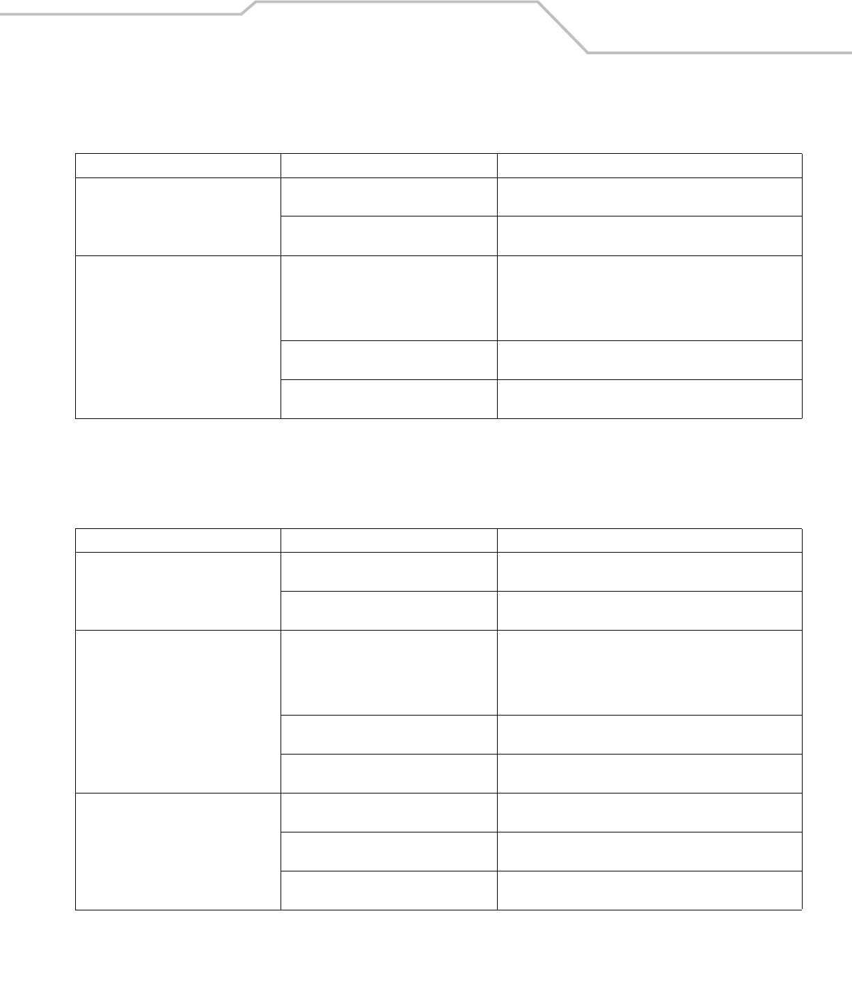
Table 5-3. Troubleshooting the Four Slot Charge Only Cradle
Problem Cause Solution
Mobile computer amber Charge LED
Indicator does not light when mobile
computer inserted.
Cradle is not receiving power. Ensure the power cable is connected securely to both the cradle
and to AC power.
Mobile computer is not correctly seated. Remove and re-insert the mobile computer into the cradle,
ensuring it is correctly seated.
Mobile computer battery is not charging. Mobile computer was removed from cradle or
cradle was unplugged from AC power too
soon.
Ensure cradle is receiving power. Ensure the mobile computer is
seated correctly. If the mobile computer battery is fully depleted, it
can take up to four hours to fully recharge a Standard Battery and
it can take up to six hours to fully recharge an Extended Life
Battery.
Battery is faulty. Verify that other batteries charge properly. If so, replace the faulty
battery.
The mobile computer is not fully seated in the
cradle.
Remove and re-insert the mobile computer into the cradle,
ensuring it is correctly seated.
Table 5-4. Troubleshooting the Four Slot Ethernet Cradle
Problem Cause Solution
Mobile computer amber Charge LED
Indicator does not light when mobile
computer inserted.
Cradle is not receiving power. Ensure the power cable is connected securely to both the cradle
and to AC power.
Mobile computer is not correctly seated. Remove and re-insert the mobile computer into the cradle,
ensuring it is correctly seated.
Mobile computer battery is not charging. Mobile computer was removed from cradle or
cradle was unplugged from AC power too
soon.
Ensure cradle is receiving power. Ensure the mobile computer is
seated correctly. If the mobile computer battery is fully depleted, it
can take up to four hours to fully recharge a Standard Battery and
it can take up to six hours to fully recharge an Extended Life
Battery.
Battery is faulty. Verify that other batteries charge properly. If so, replace the faulty
battery.
The mobile computer is not fully seated in the
cradle.
Remove and re-insert the mobile computer into the cradle,
ensuring it is correctly seated.
During data communication, no data was
transmitted, or transmitted data was
incomplete.
Mobile computer removed from cradle during
communication.
Replace mobile computer in cradle and retransmit.
Incorrect cable configuration. See the system administrator or refer to the MC3000 Integrator
Guide.
Ethernet connection error. Link LED is not lit
(see Link LED on page 4-7).
See the system administrator. Probable Ethernet connection error.
MC3000 User Guide5-8
Four Slot Spare Battery Charger
UBC Adapter
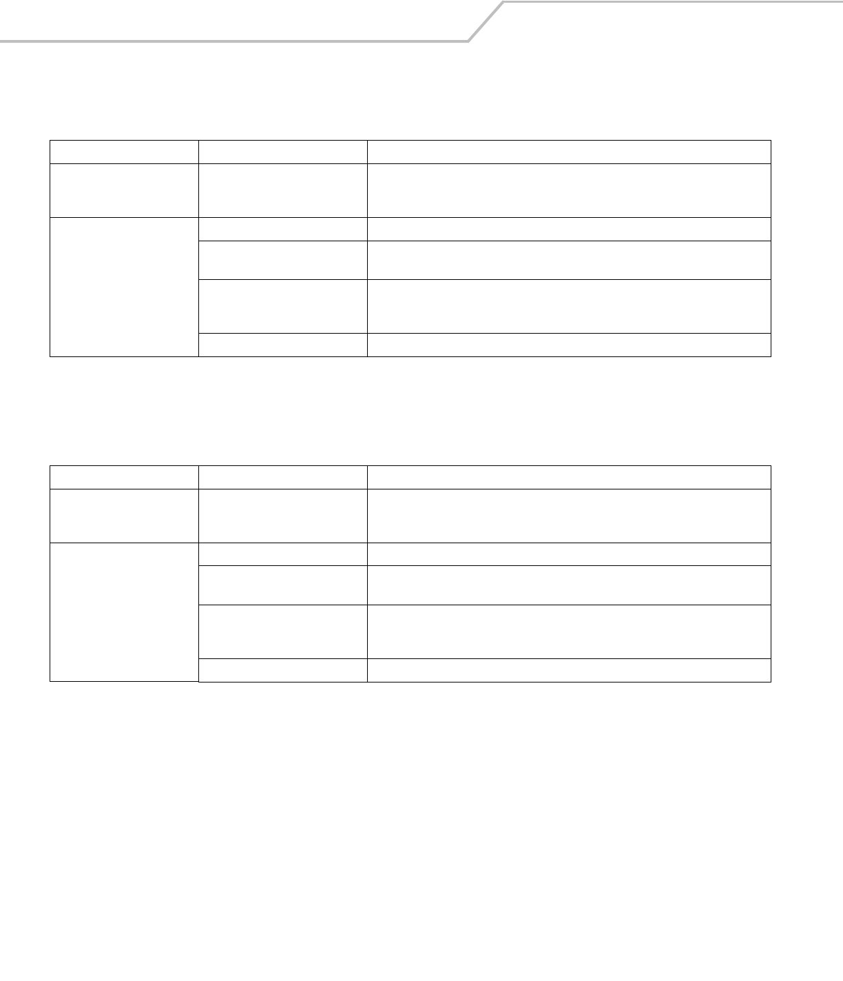
Table 5-5. Troubleshooting the Four Slot Spare Battery Charger
Symptom Possible Cause Solution
Spare Battery Charging LED
does not light when spare
battery is inserted.
Spare battery is not correctly
seated.
Remove and re-insert the spare battery into the charging slot, ensuring it is correctly
seated.
Spare battery is not charging. Charger is not receiving power. Ensure the power cable is connected securely to both the charger and to AC power.
Spare battery is not correctly
seated.
Remove and re-insert the battery into the charger, ensuring it is correctly seated.
Spare battery was removed from
charger or charger was unplugged
from AC power too soon.
Ensure charger is receiving power. Ensure the spare battery is seated correctly. If a battery
is fully depleted, it can take up to four hours to fully recharge a Standard Battery and it
can take up to six hours to fully recharge an Extended Life Battery.
Spare battery is faulty. Verify that other batteries charge properly. If so, replace the faulty battery.
Table 5-6. Troubleshooting the UBC Adapter
Symptom Possible Cause Solution
Battery Charging LED does not
light when spare battery is
inserted.
Spare battery is not correctly
seated.
Remove and re-insert the spare battery into the charging slot, ensuring it is correctly
seated.
Battery not charging. Charger is not receiving power. Ensure the power cable is connected securely to both the charger and to AC power.
Spare battery is not correctly
seated.
Remove and re-insert the spare battery into the charger, ensuring it is correctly seated.
Spare battery was removed from
charger or charger was unplugged
from AC power too soon.
Ensure charger is receiving power. Ensure the spare battery is seated correctly. If a battery
is fully depleted, it can take up to four hours to fully recharge a Standard Battery and it
can take up to six hours to fully recharge an Extended Life Battery.
Spare battery is faulty. Verify that other batteries charge properly. If so, replace the faulty battery.
Maintenance & Troubleshooting 5-9
Cables
Table 5-7. Troubleshooting the Cables
Symptom Possible Cause Solution
Mobile computer amber Charge
LED Indicator does not light
when mobile computer
attached.
Cable is not receiving power. Ensure the power cable is connected securely to both the cable and to AC power.
Mobile computer is not seated
correctly in the cable.
Remove and re-attach the mobile computer to the MC3000 connector, ensuring it is
correctly seated.
Mobile computer battery is not
charging.
Mobile computer was detached from
cable or cable was unplugged from
AC power too soon.
Ensure cable is receiving power. Ensure the mobile computer is seated correctly. If the
mobile computer battery is fully depleted, it can take up to four hours to fully recharge a
Standard Battery and it can take up to six hours to fully recharge an Extended Life Battery.
Battery is faulty. Verify that other batteries charge properly. If so, replace the faulty battery.
The mobile computer is not fully
seated in the cable.
Remove and re-attach the mobile computer to the cable, ensuring it is correctly seated.
During data communication, no
data was transmitted, or
transmitted data was
incomplete.
Cable removed from mobile
computer during communication.
Reattach cable to mobile computer and retransmit.
Incorrect cable configuration. See the system administrator or refer to the MC3000 Integrator Guide.
Communication software is not
installed or configured properly.
See the system administrator or refer to the MC3000 Integrator Guide.

MC3000 User Guide5-10

Technical Specifications
Appendix Contents
Mobile Computer And Accessory Technical Specifications . . . . . . . . . . . . . . . . . . . . . . . . . . . . . . . . . . . . . . . A-3

MC3000 Integrator GuideA-2
Technical Specifications A-3
Mobile Computer And Accessory Technical Specifications
Table A-1 summarizes the mobile computer technical specifications and intended operating environments.
Table A-2 summarizes the accessory technical specifications and the intended operating environments.
Table A-1. Mobile Computer Technical Specifications
Operating Temperature Color
14° to 122°F (-10° to +50°C)
Monochrome
-4° to 122°F (-20° to +50°C)
Storage Temperature -22° to 158°F (-30° to 70°C)
Battery Charging Temperature 32° to 104° F (0° to +40° C) ambient temperature
Humidity 5% to 95% non-condensing
Electrostatic Discharge (ESD) +/-15 kV air discharge
+/- 8 kV direct discharge
+/- 8 kV indirect discharge
Drop to Concrete 4 feet (1.2 meters)
Sealing IP54 category 2
Drop Multiple 4-foot (1.2 m) drops to concrete across operating temperature
Tumble 500 one half meter tumbles at room temperature (1000 drops)
Dimensions MC3000-K:
7.43 in L x 3.18 in W x 1.76 in D
(188.7 mm L x 80.8 mm W x 44.6 mm D)
MC3000-R:
8.33 in L x 3.18 in W x 1.57 in D
(211.6 mm L x 80.8 mm W x 39.9 mm D)
MC3000-G:
7.60 in L x 3.18 in W x 6.54 in D
(193 mm L x 80.8 mm W x 166 mm H)
Weights MC3000-R (with standard battery)* - 12.9 oz (366 g)
MC3000-K (with extended battery)* - 14.6 oz (414 g)
MC3000-G (with extended battery)* - 18.6 oz (527 g)
*For WLAN mobile computers add approximately 0.5 oz (14 g).
Display Transflective color TFT-LCD, 65K colors, 324 x 324
Monochrome FSTN, 16 shades, 320 x 320
Touch Panel Glass, analog resistive touch
Main Battery Standard: Rechargeable Lithium-Polymer 2600 mAh minimum (3.7V)
Extended Life: Rechargeable Lithium-Ion 4400 mAh minimum (3.7V)
Backup Battery Ni-MH battery (rechargeable), 20mAh (3.6V) 3 cells
Operating Platform Microsoft® Windows CE .NET 5.0 Professional
Microsoft® Windows CE .NET 5.0 Core
MC3000 Integrator GuideA-4
Processor/Memory Intel® XScale™ PXA270 312MHz with 32MB RAM/64MB Flash or
Intel® XScale™ PXA270 520MHz with 64MB RAM/64MB Flash
Interface RS232, 115.2 kbps max, and USB
WLAN Symbol Spectrum 24, 802.11abg
Keypad Options 28-Key, 38-Key and 48-Key
Data Capture:
Code 39, code 128, code 93, codabar, code 11, discrete 2 of 5, EAN-3, EAN-13, EAN-128, interleaved 2 of 5, UPCA,
UPCE and UPC/EAN supplements.
1-D Decode Capability*
Imaging Decode Capability* Code 39, code 128, code 93, codabar, code 11, discrete 2 of 5, EAN-3, EAN-13, EAN-128, interleaved 2 of 5, TLC39
(telecommunications, UPCA, UPCE, UPC/EAN supplements composite code (retail), coupon code (retail), macro
PDF-417, (macro) micro PDF-417 (T&L), micro PDF-417 (telecommunications), MSI Plessey, PDF-417 (automotive),
RSS expanded, RSS limited and RSS-14Maxi Code (UPS), Data matrix (electronics industry, US Planet (USPS), UK
4-state, Australian 4-state, Canadian 4-state, Japanese 4-state, Dutch Kix
*Go to http://software.symbol.com/ for a list of the latest supported symbologies.
SD cards Select SD cards with environmental and/or the write cycle performance specifications that meet or exceed the
application requirements.
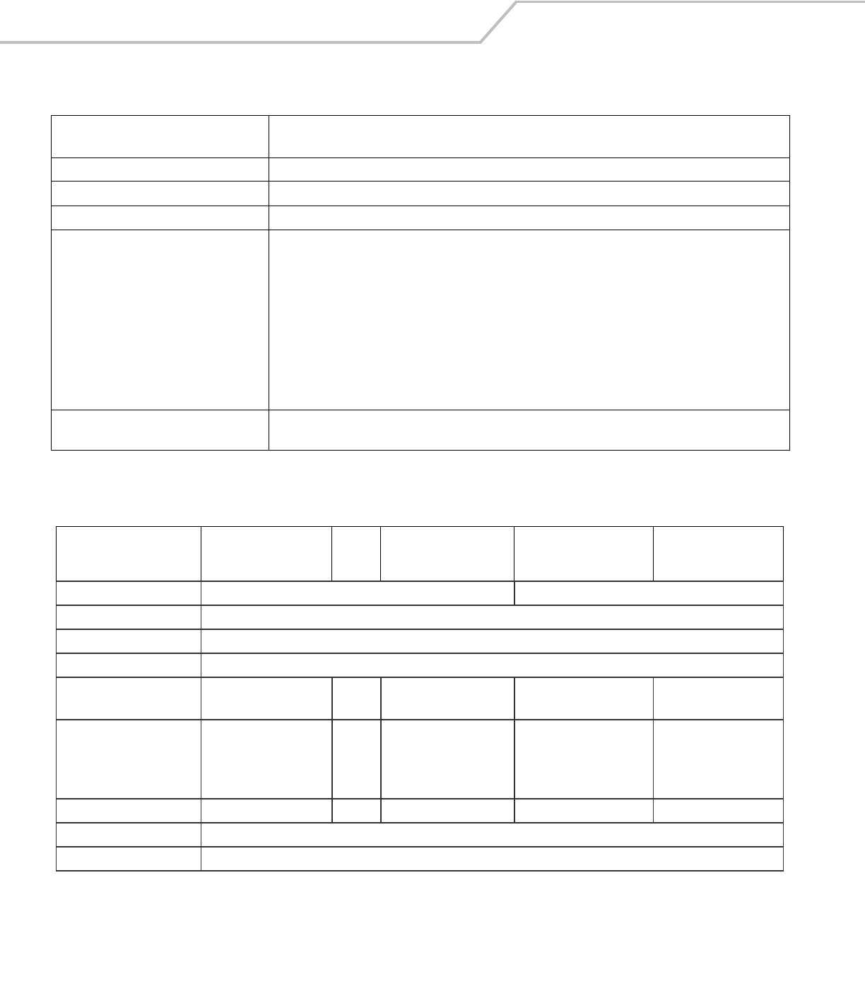
Table A-2. Accessory Specifications
Single Slot Serial/USB
Cradle Cables
Four Slot Charge Only
and Four Slot Ethernet
Cradles
Four Slot Spare Battery
Charger
Universal Battery
Charger (UBC) Adapter
Operating Temperature 32° to 122°F (0° to +50°C) 32° to 104°F (0° to +40°C)
Storage Temperature -40° to 158°F (-40° to 70°C)
Battery Charging Temperature 32° to 104° F (0° to +40° C) ambient temperature
Humidity 5% to 95% non-condensing
Size (L x D x H) 4.4 in x 5.7 in x 4.7 in
(11.2 cm x 14.5 cm x 12 cm)
6 feet
(1.83 m)
18 in x 4 in x 5 in
(45.7 cm x 10.1 cm x 12 cm)
8.25 in x 6.0 in x 1.7 in (20.96
cm x 15.24 cm x 4.32 cm)
2.5 in x 6.1 in x 1.5 in
(6.4 cm x 15.5 cm x 3.8 cm)
Weight 0.60 lbs (0.27 kg) N/A Charge only:
2.25 lbs (1.02 kg)
Ethernet:
2.38 lbs (1.08 kg)
13.6 oz (386 g) 0.25 lbs (0.11 kg)
Power 12V, 3.3 A 5.4V, 3 A 12V, 9 A 12V, 3.3 A 15V, 1.5 A
Drop 30 inches (76.2 centimeter) to vinyl covered concrete
Electrostatic Discharge (ESD) +/-15 kV air discharge, +/- 8 kV direct discharge, +/- 8 kV indirect discharge
Table A-1. Mobile Computer Technical Specifications (Continued)

Keypad Functions/Special Characters
Appendix Contents
Introduction . . . . . . . . . . . . . . . . . . . . . . . . . . . . . . . . . . . . . . . . . . . . . . . . . . . . . . . . . . . . . . . . . . . . . . . . . . . . .B-3
Keypads . . . . . . . . . . . . . . . . . . . . . . . . . . . . . . . . . . . . . . . . . . . . . . . . . . . . . . . . . . . . . . . . . . . . . . . . . . . . . . . .B-3

MC3000 User GuideB-2
Keypad Functions/Special Characters B-3
Introduction
This appendix contains the keypad functions/special characters for the 38-Key keypad. Each function/special character is included in
the table along with how the function/special character is generated.
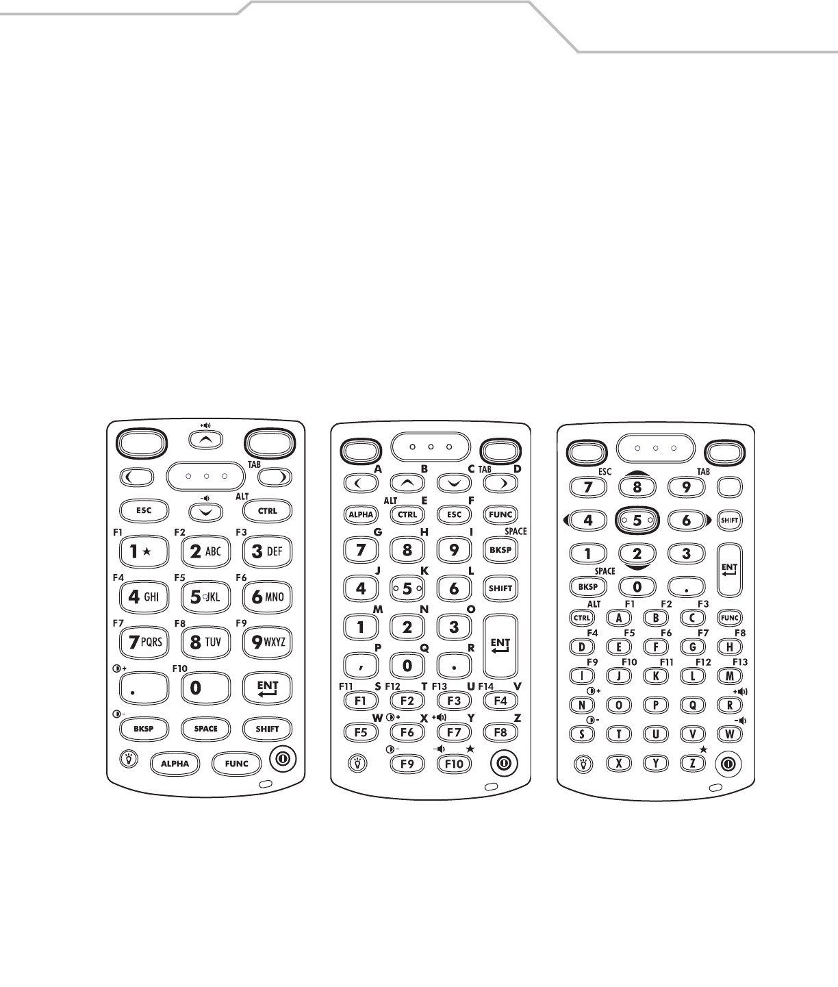
Keypads
The mobile computer is available with one of three keypads:
• 28-key keypad
• 38-key keypad
• 48-key keypad.
The keypads can be selected as necessary to support specialized applications. The keypads contain a Power button, application keys,
scroll keys and function keys. The keypad is color-coded to indicate the alternate function key (blue) values and the alternate ALPHA
key (orange) values. See Table B-1 for the special character generation. Characters can also be generated using the keyboard input
panel. For more information see, Entering Information Using the Keyboard Input Panel on page 2-16.
Figure 2-1. Keypads
28-Key Keypad 48-Key Keypad
38-Key Keypad

MC3000 User GuideB-4
Table B-1. Special Character Generation Map
Special Character
28-Key Keypad Key Sequence, Special
Character Generation
38-Key Keypad Key Sequence, Special
Character Generation
48-Key Keypad Key Sequence, Special
Character Generation
[ Use the Keyboard Input Panel* FUNC + 4 FUNC + T
] Use the Keyboard Input Panel* FUNC + 5 FUNC + U
/ Use the Keyboard Input Panel* FUNC + 9 FUNC + Q
\ Use the Keyboard Input Panel* FUNC + 3 Use the Keyboard Input Panel*
= Use the Keyboard Input Panel* FUNC + 8 FUNC + P
; Use the Keyboard Input Panel* FUNC + 6 FUNC + V
- Use the Keyboard Input Panel* FUNC + 7 FUNC + O
` Use the Keyboard Input Panel* FUNC + 2 FUNC + Y
“ Use the Keyboard Input Panel* SHIFT + FUNC + 1 Use the Keyboard Input Panel*
! SHIFT + 1 SHIFT + 1 SHIFT + 1
@ SHIFT + 2 SHIFT + 2 SHIFT + 2
# SHIFT + 3 SHIFT + 3 SHIFT + 3
$ SHIFT + 4 SHIFT + 4 SHIFT + 4
% SHIFT + 5 SHIFT + 5 SHIFT + 5
^ SHIFT + 6 SHIFT + 6 SHIFT + 6
& SHIFT + 7 SHIFT + 7 SHIFT + 7
* SHIFT + 8 SHIFT + 8 SHIFT + 8
( SHIFT + 9 SHIFT + 9 or FUNC + SHIFT + 9 SHIFT + 9
) SHIFT + 0 SHIFT + 0 or FUNC + SHIFT + 0 SHIFT + 0
‘ Use the Keyboard Input Panel* FUNC + 1 FUNC + X
“ Use the Keyboard Input Panel* Use the Keyboard Input Panel* Use the Keyboard Input Panel*
+ Use the Keyboard Input Panel* SHIFT + FUNC + 8 Use the Keyboard Input Panel*
: Use the Keyboard Input Panel* SHIFT + FUNC + 6 Use the Keyboard Input Panel*
< Use the Keyboard Input Panel* FUNC + SHIFT + ,Use the Keyboard Input Panel*
> Use the Keyboard Input Panel* FUNC + SHIFT + .SHIFT + .
? Use the Keyboard Input Panel* SHIFT + FUNC + 9 Use the Keyboard Input Panel*
_ Use the Keyboard Input Panel* SHIFT + FUNC + 7 Use the Keyboard Input Panel*
{ Use the Keyboard Input Panel* SHIFT + FUNC + 4 Use the Keyboard Input Panel*
} Use the Keyboard Input Panel* SHIFT + FUNC + 5 Use the Keyboard Input Panel*
~ Use the Keyboard Input Panel* SHIFT + FUNC + 2 Use the Keyboard Input Panel*
| N/A SHIFT + FUNC + 3 N/A
* See Entering Information Using the Keyboard Input Panel on page 2-16.

Regulatory
Appendix Contents
Introduction . . . . . . . . . . . . . . . . . . . . . . . . . . . . . . . . . . . . . . . . . . . . . . . . . . . . . . . . . . . . . . . . . . . . . . . . . . . . .B-3
Accessory Power Supply Regulatory Compliance . . . . . . . . . . . . . . . . . . . . . . . . . . . . . . . . . . . . . . . . . . . . . . . .B-3

MC3000 User GuideC-2
Regulatory C-3
Introduction
This appendix contains the accessory power supply regulatory compliance statements.
Accessory Power Supply Regulatory Compliance
Table C-1. Accessory Power Supplies, Regulatory Compliance Statements
Accessory Power Supplies Regulatory Compliance Statements
Single Slot Serial/USB Cradle Power Supply Use only a Symbol-approved power supply output rated 12 VDC and minimum 3.3 A. The power supply is
certified to EN60950 with SELV outputs. Use of alternative power supply will invalidate any approval given to
this device and may be dangerous.
Hinweis: Benutzen Sie nur eine von Symbol Technologies genehmigte Stromversorgung mit einer
Ausgangsleistung von 12 V (Gleichstrom) und mindestens 3.3 A. Die Stromversorgung ist nach EN60950 für die
Verwendung in SELV-Stromkreisen zertifiziert. Bei Verwendung eines anderen Netzteils werden alle für das
Gerät gewährten Genehmigungen außer Kraft gesetzt, und der Betrieb kann gefährlich sein.
Four Slot Spare Battery Charger Power Supply
Four Slot Charge Only Cradle Power Supply Use only a Symbol-approved power supply output rated 12 VDC and minimum 9 A. The power supply is certified
to EN60950 with SELV outputs. Use of alternative power supply will invalidate any approval given to this device
and may be dangerous.
Hinweis: Benutzen Sie nur eine von Symbol Technologies genehmigte Stromversorgung mit einer
Ausgangsleistung von 12 V (Gleichstrom) und mindestens 9 A. Die Stromversorgung ist nach EN60950 für die
Verwendung in SELV-Stromkreisen zertifiziert. Bei Verwendung eines anderen Netzteils werden alle für das
Gerät gewährten Genehmigungen außer Kraft gesetzt, und der Betrieb kann gefährlich sein.
Four Slot Ethernet Cradle Power Supply
Universal Battery Charger (UBC) Adapter
Power Supply
Use only a Symbol-approved power supply output rated 15 VDC and minimum 1.5 A. The power supply is
certified to EN60950 with SELV outputs. Use of alternative power supply will invalidate any approval given to
this device and may be dangerous.
Hinweis: Benutzen Sie nur eine von Symbol Technologies genehmigte Stromversorgung mit einer
Ausgangsleistung von 15 V (Gleichstrom) und mindestens 1.5 A. Die Stromversorgung ist nach EN60950 für die
Verwendung in SELV-Stromkreisen zertifiziert. Bei Verwendung eines anderen Netzteils werden alle für das
Gerät gewährten Genehmigungen außer Kraft gesetzt, und der Betrieb kann gefährlich sein.
Charging Cables Power Supply Use only a Symbol-approved power supply output rated 5.4 VDC and minimum 3 A. The power supply is certified
to EN60950 with SELV outputs. Use of alternative power supply will invalidate any approval given to this device
and may be dangerous.
Hinweis: Benutzen Sie nur eine von Symbol Technologies genehmigte Stromversorgung mit einer
Ausgangsleistung von 5.4 V (Gleichstrom) und mindestens 3 A. Die Stromversorgung ist nach EN60950 für die
Verwendung in SELV-Stromkreisen zertifiziert. Bei Verwendung eines anderen Netzteils werden alle für das
Gerät gewährten Genehmigungen außer Kraft gesetzt, und der Betrieb kann gefährlich sein.

MC3000 User GuideC-4

Glossary
802.11/802.11abg A radio protocol that may be used by the Symbol radio card.
Access Point Access Point (AP) refers to Symbol’s Ethernet Access Point.
It is a piece of communications equipment that manages
communications between the host computer system and
one or more wireless terminals. An AP connects to a wired
Ethernet LAN and acts as a bridge between the Ethernet
wired network and IEEE 802.11 interoperable radio-
equipped mobile units, such as a mobile computer. The AP
allows a mobile user to roam freely through a facility while
maintaining a seamless connection to the wired network.
AirBEAM® Manager AirBEAM® Manager is a comprehensive wireless network
management system that provides essential functions that
are required to configure, monitor, upgrade and
troubleshoot the wireless network and its components
(including networked mobile computers). Some features
include event notification, access point configuration,
diagnostics, statistical reports, auto-discovery, wireless
proxy agents and monitoring of access points and mobile
units.

MC3000 User GuideGL-2
AirBEAM® Smart Client AirBEAM® Smart Client is part of Symbol’s AirBEAM®
suite, which also includes AirBEAM® Safe and AirBEAM®
Manager. The AirBEAM® Smart Client system uses the
network accessible host server to store software files that
are to be downloaded to the mobile computers. The
AirBEAM® Smart Client provides the mobile computers
with the “smarts” to request software from the host. It
allows them to request, download and install software, as
well as to upload files and status data. The AirBEAM®
Smart Client uses the industry standard FTP or TFTP file
transfer protocols to check the host system for updates, and
if necessary, to transfer updated software. Most often,
AirBEAM® Smart Client is used with wireless networks,
but any TCP/IP connection can be used. For more
information, refer to the AirBEAM® Smart Windows® CE
Client Product Reference Guide (p/n 72-63060-xx).
AP See Access Point.
Aperture The opening in an optical system defined by a lens or baffle
that establishes the field of view.
ASCII American Standard Code for Information Interchange. A 7
bit-plus-parity code representing 128 letters, numerals,
punctuation marks and control characters. It is a standard
data transmission code in the U.S.
Autodiscrimination The ability of an interface controller to determine the code
type of a scanned bar code. After this determination is
made, the information content is decoded.
Bar The dark element in a printed bar code symbol.
Bar Code A pattern of variable-width bars and spaces which
represents numeric or alphanumeric data in machine-
readable form. The general format of a bar code symbol
consists of a leading margin, start character, data or
message character, check character (if any), stop character,
and trailing margin. Within this framework, each
recognizable symbology uses its own unique format. See
Symbology.
Bar Code Density The number of characters represented per unit of
measurement (e.g., characters per inch).
Bar Height The dimension of a bar measured perpendicular to the bar
width.
Bar Width Thickness of a bar measured from the edge closest to the
symbol start character to the trailing edge of the same bar.
Bit Binary digit. One bit is the basic unit of binary information.
Generally, eight consecutive bits compose one byte of data.
The pattern of 0 and 1 values within the byte determines its
meaning.
Bits per Second (bps) Bits transmitted or received.
Bit Binary digit. One bit is the basic unit of binary information.
Generally, eight consecutive bits compose one byte of data.
The pattern of 0 and 1 values within the byte determines its
meaning.
bps See Bits Per Second.

Glossary GL-3
Byte On an addressable boundary, eight adjacent binary digits (0
and 1) combined in a pattern to represent a specific
character or numeric value. Bits are numbered from the
right, 0 through 7, with bit 0 the low-order bit. One byte in
memory is used to store one ASCII character.
boot or boot-up The process a computer goes through when it starts. During
boot-up, the computer can run self-diagnostic tests and
configure hardware and software.
CDRH Center for Devices and Radiological Health. A federal
agency responsible for regulating laser product safety. This
agency specifies various laser operation classes based on
power output during operation.
CDRH Class 1 This is the lowest power CDRH laser classification. This
class is considered intrinsically safe, even if all laser output
were directed into the eye's pupil. There are no special
operating procedures for this class.
CDRH Class 2 No additional software mechanisms are needed to conform
to this limit. Laser operation in this class poses no danger
for unintentional direct human exposure.
Character A pattern of bars and spaces which either directly
represents data or indicates a control function, such as a
number, letter, punctuation mark, or communications
control contained in a message.
Character Set Those characters available for encoding in a particular bar
code symbology.
Check Digit A digit used to verify a correct symbol decode. The scanner
inserts the decoded data into an arithmetic formula and
checks that the resulting number matches the encoded
check digit. Check digits are required for UPC but are
optional for other symbologies. Using check digits
decreases the chance of substitution errors when a symbol
is decoded.
Codabar A discrete self-checking code with a character set
consisting of digits 0 to 9 and six additional characters: ( -
$ : / , +).
Code 128 A high density symbology which allows the controller to
encode all 128 ASCII characters without adding extra
symbol elements.
Code 3 of 9 (Code 39) A versatile and widely used alphanumeric bar code
symbology with a set of 43 character types, including all
uppercase letters, numerals from 0 to 9 and 7 special
characters (- . / + % $ and space). The code name is derived
from the fact that 3 of 9 elements representing a character
are wide, while the remaining 6 are narrow.
Code 93 An industrial symbology compatible with Code 39 but
offering a full character ASCII set and a higher coding
density than Code 39.
Code Length Number of data characters in a bar code between the start
and stop characters, not including those characters.
Cold Boot A cold boot restarts the mobile computer and erases all
user stored records and entries.

MC3000 User GuideGL-4
COM port Communication port; ports are identified by number, e.g.,
COM1, COM2.
Continuous Code A bar code or symbol in which all spaces within the symbol
are parts of characters. There are no intercharacter gaps in
a continuous code. The absence of gaps allows for greater
information density.
Cradle A cradle is used for charging the terminal battery and for
communicating with a host computer, and provides a
storage place for the terminal when not in use.
Dead Zone An area within a scanner's field of view, in which specular
reflection may prevent a successful decode.
Decode To recognize a bar code symbology (e.g., UPC/EAN) and
then analyze the content of the specific bar code scanned.
Decode Algorithm A decoding scheme that converts pulse widths into data
representation of the letters or numbers encoded within a
bar code symbol.
Decryption Decryption is the decoding and unscrambling of received
encrypted data. Also see, Encryption and Key.
Depth of Field The range between minimum and maximum distances at
which a scanner can read a symbol with a certain minimum
element width.
Discrete Code A bar code or symbol in which the spaces between
characters (intercharacter gaps) are not part of the code.
Discrete 2 of 5 A binary bar code symbology representing each character
by a group of five bars, two of which are wide. The location
of wide bars in the group determines which character is
encoded; spaces are insignificant. Only numeric characters
(0 to 9) and START/STOP characters may be encoded.
EAN European Article Number. This European/International
version of the UPC provides its own coding format and
symbology standards. Element dimensions are specified
metrically. EAN is used primarily in retail.
Element Generic term for a bar or space.
Encoded Area Total linear dimension occupied by all characters of a code
pattern, including start/stop characters and data.
ESD Electro-Static Discharge
ESN Electronic Serial Number. The unique hardware number
associated with a cellular device, which is transmitted to
the system when the device communicates with the
cellular system.
Ethernet Ethernet communication port. Allows a wired interface to a
radio network.
Flash Memory Flash memory is nonvolatile, semi-permanent storage that
can be electronically erased in the circuit and
reprogrammed. Mobile computers may use Flash memory
to store the operating system (ROM-DOS), the terminal
emulators, and the Citrix ICA Client for DOS.
FTP See File Transfer Protocol.

Glossary GL-5
Flash Memory Flash memory is responsible for storing the system
firmware and is non-volatile. If the system power is
interrupted the data is not be lost.
Gateway Address An IP address for a network gateway or router. A mobile
computer may be part of a subnet as specified by its IP
address and Netmask. It can send packets directly to any
node on the same subnet. If the destination node is on a
different subnet, then the terminal sends the packet to the
gateway first. The gateway determines how to route the
packet to the destination subnet. This field is an option
used by networks that require gateways.
Hard Reset See Cold Boot.
Hz Hertz; A unit of frequency equal to one cycle per second.
Host Computer A computer that serves other terminals in a network,
providing such services as computation, database access,
supervisory programs and network control.
IDE Intelligent drive electronics. Refers to the solid-state hard
drive type.
IEC International Electrotechnical Commission. This
international agency regulates laser safety by specifying
various laser operation classes based on power output
during operation.
IEC (825) Class 1 This is the lowest power IEC laser classification.
Conformity is ensured through a software restriction of 120
seconds of laser operation within any 1000 second window
and an automatic laser shutdown if the scanner's
oscillating mirror fails.
Interleaved 2 of 5 A binary bar code symbology representing character pairs
in groups of five bars and five interleaved spaces.
Interleaving provides for greater information density. The
location of wide elements (bar/spaces) within each
group determines which characters are encoded. This
continuous code type uses no intercharacter spaces. Only
numeric (0 to 9) and START/STOP characters may be
encoded.
imaging scanning Mobile computers with an integrated imager use digital
camera technology to take a digital picture of a bar code,
store the resulting image in memory and execute state-of-
the-art software decoding algorithms to extract the data
from the image.
Intercharacter Gap The space between two adjacent bar code characters in a
discrete code.
Interleaved Bar Code A bar code in which characters are paired together, using
bars to represent the first character and the intervening
spaces to represent the second.

MC3000 User GuideGL-6
Interleaved 2 of 5 A binary bar code symbology representing character pairs
in groups of five bars and five interleaved spaces.
Interleaving provides for greater information density. The
location of wide elements (bar/spaces) within each group
determines which characters are encoded. This continuous
code type uses no intercharacter spaces. Only numeric (0 to
9) and START/STOP characters may be encoded.
Internet Protocol Address See IP.
IP Internet Protocol. The IP part of the TCP/IP communications
protocol. IP implements the network layer (layer 3) of the
protocol, which contains a network address and is used to
route a message to a different network or subnetwork. IP
accepts “packets” from the layer 4 transport protocol (TCP
or UDP), adds its own header to it and delivers a
“datagram” to the layer 2 data link protocol. It may also
break the packet into fragments to support the maximum
transmission unit (MTU) of the network.
IP Address (Internet Protocol address) The address of a computer
attached to an IP network. Every client and server station
must have a unique IP address. A 32-bit address used by a
computer on a IP network. Client workstations have either
a permanent address or one that is dynamically assigned to
them each session. IP addresses are written as four sets of
numbers separated by periods; for example, 204.171.64.2.
LAN Local area network. A radio network that supports data
communication within a local area, such as within a
warehouse of building.
laser scanner A type of bar code reader that uses a beam of laser light.
LASER Light Amplification by Stimulated Emission of
Radiation.The laser is an intense light source. Light from a
laser is all the same frequency, unlike the output of an
incandescent bulb. Laser light is typically coherent and has
a high energy density.
Laser Diode A gallium-arsenide semiconductor type of laser connected
to a power source to generate a laser beam. This laser type
is a compact source of coherent light.
LED Indicator A semiconductor diode (LED - Light Emitting Diode) used as
an indicator, often in digital displays. The semiconductor
uses applied voltage to produce light of a certain frequency
determined by the semiconductor's particular chemical
composition.
Light Emitting Diode See LED.
MC Mobile Computer.
MIL 1 mil = 1 thousandth of an inch.
MIN Mobile Identification Number. The unique account number
associated with a cellular device. It is broadcast by the
cellular device when accessing the cellular system.
Misread (Misdecode) A condition which occurs when the data output of a reader
or interface controller does not agree with the data
encoded within a bar code symbol.

Glossary GL-7
Mobile Computer In this text, mobile computer refers to the Symbol portable
computer. It can be set up to run as a stand-alone device,
or it can be set up to communicate with a network, using
wireless radio technology.
Nominal The exact (or ideal) intended value for a specified
parameter. Tolerances are specified as positive and
negative deviations from this value.
Nominal Size Standard size for a bar code symbol. Most UPC/EAN codes
are used over a range of magnifications (e.g., from 0.80 to
2.00 of nominal).
NVM Non-Volatile Memory.
Parameter A variable that can have different values assigned to it.
PDT Portable Data Terminal.
Percent Decode The average probability that a single scan of a bar code
would result in a successful decode. In a well-designed bar
code scanning system, that probability should approach
near 100%.
Quiet Zone A clear space, containing no dark marks, which precedes
the start character of a bar code symbol and follows the
stop character.
RAM Random Access Memory. Data in RAM can be accessed in
random order, and quickly written and read.
Reflectance Amount of light returned from an illuminated surface.
Resolution The narrowest element dimension which is distinguished
by a particular reading device or printed with a particular
device or method.
RF Radio Frequency.
ROM Read-Only Memory. Data stored in ROM cannot be changed
or removed.
ROM-DOS The name of the licensed Disk Operating System loaded
into the terminal’s flash file system.
Router A device that connects networks and supports the required
protocols for packet filtering. Routers are typically used to
extend the range of cabling and to organize the topology of
a network into subnets. See Subnet.
RS232 An Electronic Industries Association (EIA) standard that
defines the connector, connector pins, and signals used to
transfer data serially from one device to another.
Scan Area Area intended to contain a symbol.
Scanner An electronic device used to scan bar code symbols and
produce a digitized pattern that corresponds to the bars and
spaces of the symbol. Its three main components are:
1. Light source (laser or photoelectric cell) - illuminates a
bar code.
2. Photodetector - registers the difference in reflected light
(more light reflected from spaces).
3. Signal conditioning circuit - transforms optical detector
output into a digitized bar pattern.

MC3000 User GuideGL-8
Scanning Mode The scanner is energized, programmed and ready to read a
bar code.
Scanning Sequence A method of programming or configuring parameters for a
bar code reading system by scanning bar code menus.
SDK Software Development Kit
Self-Checking Code A symbology that uses a checking algorithm to detect
encoding errors within the characters of a bar code symbol.
Shared Key Shared Key authentication is an algorithm where both the
AP and the MU share an authentication key.
SID System Identification code. An identifier issued by the FCC
for each market. It is also broadcast by the cellular carriers
to allow cellular devices to distinguish between the home
and roaming service.
SMDK Symbol Mobility Developer’s Kit.
Soft Reset See Warm Boot.
Space The lighter element of a bar code formed by the background
between bars.
Specular Reflection The mirror-like direct reflection of light from a surface,
which can cause difficulty decoding a bar code.
Spring Radio Protocol A radio protocol that may be used by the Symbol radio
card. Symbol Radio cards that use the Spring protocol also
have an Net ID.
Start/Stop Character A pattern of bars and spaces that provides the scanner with
start and stop reading instructions and scanning direction.
The start and stop characters are normally to the left and
right margins of a horizontal code.
STEP Symbol Terminal Enabler Program.
Subnet A subset of nodes on a network that are serviced by the
same router. See Router.
Subnet Mask A 32-bit number used to separate the network and host
sections of an IP address. A custom subnet mask subdivides
an IP network into smaller subsections. The mask is a
binary pattern that is matched up with the IP address to turn
part of the host ID address field into a field for subnets.
Default is often 255.255.255.0.
Substrate A foundation material on which a substance or image is
placed.
SVTP Symbol Virtual Terminal Program.
Symbol A scannable unit that encodes data within the conventions
of a certain symbology, usually including start/stop
characters, quiet zones, data characters and check
characters.
Symbol Aspect Ratio The ratio of symbol height to symbol width.
Symbol Height The distance between the outside edges of the quiet zones
of the first row and the last row.

Glossary GL-9
Symbol Length Length of symbol measured from the beginning of the quiet
zone (margin) adjacent to the start character to the end of
the quiet zone (margin) adjacent to a stop character.
Symbology The structural rules and conventions for representing data
within a particular bar code type (e.g. UPC/EAN, Code 39,
PDF417, etc.).
Tolerance Allowable deviation from the nominal bar or space width.
UPC Universal Product Code. A relatively complex numeric
symbology. Each character consists of two bars and two
spaces, each of which is any of four widths. The standard
symbology for retail food packages in the United States.
Visible Laser Diode (VLD) A solid state device which produces visible laser light.
WAN Wide-Area Network. A radio network that supports data
communication beyond a local area. That is, information
can be sent across a city, state, or even nationwide.
Warm Boot A warm boot restarts the mobile computer by closing all
running programs. All data that is not saved to flash
memory is lost.
Wireless Local Area Network (WLAN) See LAN.
Wireless Wide Area Network (WWAN) See WAN.
WNMP (Wireless Network Management Protocol) This is Symbol’s
proprietary MAC layer protocol used for inter access point
communication and other MAC layer communication.

MC3000 User GuideGL-10

Numerics
28-key keypad . . . . . . . . . . . . . . . . . . . . . . . . . . 2-4, B-3
38-key keypad . . . . . . . . . . . . . . . . . . . . . . . . . . 2-6, B-3
48-key keypad . . . . . . . . . . . . . . . . . . . . . . . . . . 2-8, B-3
802.11 . . . . . . . . . . . . . . . . . . . . . . . . . . . . . . . . . . . A-4
A
accessories . . . . . . . . . . . . . . . . . . . . . . . . . . . . . . . .1-3
cables . . . . . . . . . . . . . . . . . . . . . . . . . . . . . . . .4-9
four slot charge only cradle . . . . . . . . . . . 4-3, 4-6
LED indicators . . . . . . . . . . . . . . . . . . . . .4-7
four slot cradles
battery charging . . . . . . . . . . . . . . . . . . . .4-6
four slot spare battery charger . . . . . . . . . . . . .4-3
battery charging . . . . . . . . . . . . . . . . . . . .4-8
LED indicators . . . . . . . . . . . . . . . . . . . . .4-8
MC3000 communication/charge cables
battery charging . . . . . . . . . . . . . . . . . . .4-10
LED indicators . . . . . . . . . . . . . . . . . . . .4-10
plastic holster . . . . . . . . . . . . . . . . . . . . 4-14, 4-16
SD card . . . . . . . . . . . . . . . . . . . . . . . . . . . . . .4-13
single slot serial/USB cradle . . . . . . . . . . 4-3, 4-4
battery charging . . . . . . . . . . . . . . . . . . . .4-4
LED indicators . . . . . . . . . . . . . . . . . . . . .4-5
stylus . . . . . . . . . . . . . . . . . . . . . . . . . . . . . . . . .1-3
UBC adapter . . . . . . . . . . . . . . . . . . . . . . . . . . .4-3
battery charging . . . . . . . . . . . . . . . . . . .4-11
LED indicators . . . . . . . . . . . . . . . . . . . .4-12
active and indicate programs . . . . . . . . . . . . . . . . .2-11
active tasks . . . . . . . . . . . . . . . . . . . . . . . . . . . . . . .2-14
ActiveSync . . . . . . . . . . . . . . . . . . . . . . . . . . . . . . . . . xv
Adaptive Frequency Hopping . . . . . . . . . . . . . . . . . . 3-3
AFH . . . . . . . . . . . . . . . . . . . . . . . . . . . . . . . . . . . . . . 3-3
aiming options
aiming pattern . . . . . . . . . . . . . . . . . . . . . . . . 2-19
attaching strap/door assembly . . . . . . . . . . .1-14, 1-15
B
backup battery specification . . . . . . . . . . . . . . . . . . A-3
battery
charging . . . . . . . . . . . . . . . . . . . . . . . . . . . . . . 1-9
temperature range . . . . . . . . . . . . . A-3, A-4
install . . . . . . . . . . . . . . . . . . . . . . . . . . . . . . . . 1-6
removal . . . . . . . . . . . . . . . . . . . . . . . . . . . . . 1-12
specification . . . . . . . . . . . . . . . . . . . . . . . . . . A-3
status . . . . . . . . . . . . . . . . . . . . . . . . . . . . . . . 2-11
battery charge status . . . . . . . . . . . . . . . . . . . . . . . 2-11
battery chargers
four slot spare battery charger
battery charging . . . . . . . . . . . . . . . . . . . 4-8
LED indicators . . . . . . . . . . . . . . . . . . . . 4-8
MC3000 communication/charge cables
battery charging . . . . . . . . . . . . . . . . . . 4-10
LED indicators . . . . . . . . . . . . . . . . . . . 4-10
UBC adapter
battery charging . . . . . . . . . . . . . . . . . . 4-11
LED indicators . . . . . . . . . . . . . . . . . . . 4-12
battery charging . . . . . . . . . . . . . . . . . . . . . . . . . . . . 1-9
backup battery . . . . . . . . . . . . . . . . . . . . . . . . . 1-9
four slot cradles . . . . . . . . . . . . . . . . . . . . . . . 4-6
four slot spare battery charger . . . . . . . . . . . . 4-8
Index

MC3000 User GuideIN-2
main battery . . . . . . . . . . . . . . . . . . . . . . . . . . .1-9
MC3000 communication/charge cables . . . . .4-10
battery charging . . . . . . . . . . . . . . . . . . .4-10
temperature range . . . . . . . . . . . . . . . . . . . . . .1-9
UBC adapter . . . . . . . . . . . . . . . . . . . . . . . . . .4-11
battery status . . . . . . . . . . . . . . . . . . . . . . . . . . . . . .2-11
beeper . . . . . . . . . . . . . . . . . . . . . . . . . . . . . . . . . . . .1-4
beeper volume . . . . . . . . . . . . . . . . . . . . . . . . . . . . . .2-3
Bluetooth . . . . . . . . . . . . . . . . . . . . . . . . . . . . . . . . . .3-3
ActiveSync . . . . . . . . . . . . . . . . . . . . . . . . . . . .3-7
bonding . . . . . . . . . . . . . . . . . . . . . . . . . . . . . .3-10
deleting bonded device . . . . . . . . . . . . . . . . . .3-12
dial-up networking services . . . . . . . . . . . . . .3-16
disable . . . . . . . . . . . . . . . . . . . . . . . . . . . . . . . .3-4
discovering devices . . . . . . . . . . . . . . . . . . . . . .3-8
discovering services . . . . . . . . . . . . . . . . . . . .3-13
enable . . . . . . . . . . . . . . . . . . . . . . . . . . . . . . . .3-5
file transfer services . . . . . . . . . . . . . . . . . . . .3-14
OBEX object push services . . . . . . . . . . . . . . .3-18
personal area network services . . . . . . . . . . .3-21
renaming bonded device . . . . . . . . . . . . . . . . .3-11
turning off . . . . . . . . . . . . . . . . . . . . . . . . . . . . .3-4
turning on . . . . . . . . . . . . . . . . . . . . . . . . . . . . .3-5
wizard mode . . . . . . . . . . . . . . . . . . . . . . . . . . .3-5
bluetooth
adaptive frequency hopping . . . . . . . . . . . . . . .3-3
icon . . . . . . . . . . . . . . . . . . . . . . . . . . . . 2-11, 2-12
Bluetooth security . . . . . . . . . . . . . . . . . . . . . . . . . . .3-3
bonding, Bluetooth . . . . . . . . . . . . . . . . . . . . . . . . . .3-10
boot
cold . . . . . . . . . . . . . . . . . . . . . . . . . . . . . . . . . .3-5
warm . . . . . . . . . . . . . . . . . . . . . . . . . . . . . . . . .3-5
bullets . . . . . . . . . . . . . . . . . . . . . . . . . . . . . . . . . . . . xv
C
cables . . . . . . . . . . . . . . . . . . . . . . . . . . . . . . . . . . . . .4-3
calibration screen . . . . . . . . . . . . . . . . . . . . . . . . . .1-11
characters, special . . . . . . . . . . . . . . . . . . . . . . . . . . B-4
charge battery . . . . . . . . . . . . . . . . . . . . . . . . . . . . . .1-9
charge LED indicator . . . . . . . . . . . . . . . . . . . . .1-4, 1-6
charging
spare batteries . . . . . . . . . . . . . . . . . . . . . . . .1-10
temperature range . . . . . . . . . . . . . . . . . A-3, A-4
charging battery . . . . . . . . . . . . . . . . . . . . . . . . . . . . .1-9
charging, temperature range . . . . . . . . . . . . . . . . . . .1-9
cleaning . . . . . . . . . . . . . . . . . . . . . . . . . . . . . . . . . . .5-3
clock, display . . . . . . . . . . . . . . . . . . . . . . . . . . . . . .2-14
cold boot . . . . . . . . . . . . . . . . . . . . . . . . . . . . . 2-23, 3-5
communication status . . . . . . . . . . . . . . . . . . . . . . .2-11
contrast settings . . . . . . . . . . . . . . . . . . . . . . . . . . . .2-3
conventions
notational . . . . . . . . . . . . . . . . . . . . . . . . . . . . . xv
cradles
four slot charge only cradle . . . . . . . . . . . 4-3, 4-6
LED indicators . . . . . . . . . . . . . . . . . . . . .4-7
four slot cradles
battery charging . . . . . . . . . . . . . . . . . . . .4-6
single slot serial/USB cradle . . . . . . . . . . . . . .4-3
battery charging . . . . . . . . . . . . . . . . . . . 4-4
LED indicators . . . . . . . . . . . . . . . . . . . . . 4-5
troubleshooting . . . . . . . . . . . . . . . . . . . . . . . . 5-8
D
data backup . . . . . . . . . . . . . . . . . . . . . . . . . . . . . . . 1-9
data capture specifications . . . . . . . . . . . . . . . . . . . A-4
DCP . . . . . . . . . . . . . . . . . . . . . . . . . . . . . . . . . . . xv, 1-3
decode ranges . . . . . . . . . . . . . . . . . . . . . . . .2-17, 2-20
deleting Bluetooth bond . . . . . . . . . . . . . . . . . . . . . 3-12
demo window . . . . . . . . . . . . . . . . . . . . 1-11, 1-12, 2-10
desktop window . . . . . . . . . . . . . . . . . . . . . . . . . . . 2-10
device configuration package . . . . . . . . . . . . . . . . . . 1-3
Device Configuration Package, see DCP
dimensions . . . . . . . . . . . . . . . . . . . . . . . . . . . . . . . . A-3
directory structure . . . . . . . . . . . . . . . . . . . . . . . . . 2-24
display clock . . . . . . . . . . . . . . . . . . . . . . . . . . . . . . 2-14
display contrast . . . . . . . . . . . . . . . . . . . . . . . . . . . . 2-3
display specification . . . . . . . . . . . . . . . . . . . . . . . . . A-3
documentation updates . . . . . . . . . . . . . . . . . . . . . . . xv
documents . . . . . . . . . . . . . . . . . . . . . . . . . . . . . . . 2-12
E
electro-static discharge
end task . . . . . . . . . . . . . . . . . . . . . . . . . . . . . . . . . 2-14
entering data with scanner . . . . . . . . . . . . . . . . . . 2-16
entering information . . . . . . . . . . . . . . . . . . . . . . . . 2-15
scanning . . . . . . . . . . . . . . . . . . . . . . . . . . . . . 2-16
ESD . . . . . . . . . . . . . . . . . . . . . . . . . . . . . . . . . 4-13, A-3
F
fabric holster . . . . . . . . . . . . . . . . . . . . . . . . . . .1-3, 4-16
favorites . . . . . . . . . . . . . . . . . . . . . . . . . . . . . . . . . 2-12
file folders . . . . . . . . . . . . . . . . . . . . . . . . . . . . . . . . 2-24
file system directory structure . . . . . . . . . . . . . . . . 2-24
four slot charge only cradle . . . . . . . . . . . . 1-3, 4-3, 4-6
LED indicators . . . . . . . . . . . . . . . . . . . . . . . . . 4-7
four slot cradles . . . . . . . . . . . . . . . . . . . . . . . . . . . . 1-9
battery charging . . . . . . . . . . . . . . . . . . . . . . . . 4-6
four slot Ethernet cradle . . . . . . . . . . . . . . . . . . . . . . 1-3
four slot spare battery charger . . . . . . . . . 1-3, 1-9, 1-10
battery charging . . . . . . . . . . . . . . . . . . . . . . . . 4-8
LED indicators . . . . . . . . . . . . . . . . . . . . . . . . . 4-8
troubleshooting . . . . . . . . . . . . . . . . . . . . . . . . 5-8
frequency-hopping spread spectrum . . . . . . . . . . . . 3-3
function status . . . . . . . . . . . . . . . . . . . . . . . . . . . . 2-11
H
hard reset . . . . . . . . . . . . . . . . . . . . . . . . . . . . .2-23, 3-5
headset jack . . . . . . . . . . . . . . . . . . . . . . . . . . . . . . . 1-5
help . . . . . . . . . . . . . . . . . . . . . . . . . . . . . . . . . . . . . 2-12
holster, fabric . . . . . . . . . . . . . . . . . . . . . . . . . .1-3, 4-16
holster, plastic . . . . . . . . . . . . . . . . . . . . . . . . .1-3, 4-14
humidity . . . . . . . . . . . . . . . . . . . . . . . . . . . . . . . . . . A-3

Index IN-3
I
icons
bluetooth . . . . . . . . . . . . . . . . . . . . . . . 2-11, 2-12
Imager
image capture . . . . . . . . . . . . . . . . . . . . . . . . 2-19
imager . . . . . . . . . . . . . . . . . . . . . . . . . . . . . . . . . . . 2-19
aiming . . . . . . . . . . . . . . . . . . . . . . . . . . . . . . 2-19
decode mode . . . . . . . . . . . . . . . . . . . . . . . . . 2-19
function . . . . . . . . . . . . . . . . . . . . . . . . . . . . . 2-19
operational modes . . . . . . . . . . . . . . . . . . . . . 2-19
imager decode ranges . . . . . . . . . . . . . . . . . . . . . . 2-22
imager scanning . . . . . . . . . . . . . . . . . . . . . . . . . . . 2-19
indicator LED bar . . . . . . . . . . . . . . . . . . . . .1-4, 1-6, 4-4
Industry Scientific and Medical . . . . . . . . . . . . . . . . 3-3
information, service . . . . . . . . . . . . . . . . . . . . . . . . . xvi
internet
wireless connection . . . . . . . . . . . . . . . . . . . . 2-25
internet connection . . . . . . . . . . . . . . . . . . . . . . . . . 2-25
K
keypad
28-key . . . . . . . . . . . . . . . . . . . . . . . . .2-3, 2-4, B-3
38-key . . . . . . . . . . . . . . . . . . . . . . . . .2-3, 2-6, B-3
48-key . . . . . . . . . . . . . . . . . . . . . . . . .2-3, 2-8, B-3
keypad configurations . . . . . . . . . . . . . . . . . . . . . . . . 2-3
keypad functions . . . . . . . . . . . . . . . . . . . . . . . . . . . . B-3
keypad special functions . . . . . . . . . . . . . . . . . . . . . 2-3
L
laser decode ranges . . . . . . . . . . . . . . . . . . . . . . . . 2-18
laser scanning . . . . . . . . . . . . . . . . . . . . . . . . . . . . . 2-16
M
main battery . . . . . . . . . . . . . . . . . . . . . . . . . . . . . . . 1-9
charging . . . . . . . . . . . . . . . . . . . . . . . . . . . . . . 1-6
temperature range . . . . . . . . . . . . . A-3, A-4
inserting . . . . . . . . . . . . . . . . . . . . . . . . . . . . . . 1-6
main battery removal . . . . . . . . . . . . . . . . . . . . . . . 1-12
maintenance . . . . . . . . . . . . . . . . . . . . . . . . . . . . . . . 5-3
MC3000 communication/charge cables . . . . . . . . . . 4-9
battery charging . . . . . . . . . . . . . . . . . . . . . . . 4-10
LED indicators . . . . . . . . . . . . . . . . . . . . . . . . 4-10
MC3000-K parts . . . . . . . . . . . . . . . . . . . . . . . . 1-4, 1-5
MC3000-R parts . . . . . . . . . . . . . . . . . . . . . . . . 1-4, 1-5
microphone . . . . . . . . . . . . . . . . . . . . . . . . . . . . . . . . 1-4
mobile computer
cold boot . . . . . . . . . . . . . . . . . . . . . . . . . . . . 2-23
hard reset . . . . . . . . . . . . . . . . . . . . . . . . . . . . 2-23
power on . . . . . . . . . . . . . . . . . . . . . . . . . . . . . 2-3
reset . . . . . . . . . . . . . . . . . . . . . . . . . . . . . . . . 2-23
scanning . . . . . . . . . . . . . . . . . . . . . . . . . . . . . 2-16
soft reset . . . . . . . . . . . . . . . . . . . . . . . . . . . . 2-23
warm boot . . . . . . . . . . . . . . . . . . . . . . . . . . . 2-23
Monarch printer cable . . . . . . . . . . . . . . . . . . . 1-3, 4-9
N
navigating software . . . . . . . . . . . . . . . . . . . . . . . . . .2-3
O
operating
environment . . . . . . . . . . . . . . . . . . . . . . . . . . A-3
platforms . . . . . . . . . . . . . . . . . . . . . . . . . . . . . A-3
temperature . . . . . . . . . . . . . . . . . . . . . . . . . . A-3
OS . . . . . . . . . . . . . . . . . . . . . . . . . . . . . . . . . . . . . . A-3
O’Neil printer cable . . . . . . . . . . . . . . . . . . . . . . 1-3, 4-9
P
pair with a remote device . . . . . . . . . . . . . . . . . . . . .3-7
parts . . . . . . . . . . . . . . . . . . . . . . . . . . . . . . 1-4, 1-5, 1-6
PDF417
slab raster option . . . . . . . . . . . . . . . . . . . . . .2-19
smart raster . . . . . . . . . . . . . . . . . . . . . . . . . .2-19
plastic holster . . . . . . . . . . . . . . . . . . . . . . . . . 1-3, 4-14
platform SDK . . . . . . . . . . . . . . . . . . . . . . . . . . . . . . . .xv
power button . . . . . . . . . . . . . . . . . . . . . . . . . . . . . . .2-3
power supply . . . . . . . . . . . . . . . . . . . . . . . . . . . . . . .1-3
power supply regulatory compliance . . . . . . . . . . . .B-3
processor/memory specifications . . . . . . . . . . . . . . A-4
program menu . . . . . . . . . . . . . . . . . . . . . . . . . . . . .2-13
properties . . . . . . . . . . . . . . . . . . . . . . . . . . . . . . . . .2-14
R
radio module specifications . . . . . . . . . . . . . . . . . . A-4
receiver . . . . . . . . . . . . . . . . . . . . . . . . . . . . . . . . . . .1-4
receiver volume . . . . . . . . . . . . . . . . . . . . . . . . . . . . .2-3
regulatory compliance, power supply . . . . . . . . . . . .B-3
remove battery . . . . . . . . . . . . . . . . . . . . . . . . . . . . .1-12
remove the Strap/Door Assembly . . . . . . . . . 1-14, 1-15
renaming Bluetooth bond . . . . . . . . . . . . . . . . . . . .3-11
replace the strap/door assembly . . . . . . . . . . 1-14, 1-15
reset
hard . . . . . . . . . . . . . . . . . . . . . . . . . . . . . . . . . .3-5
soft . . . . . . . . . . . . . . . . . . . . . . . . . . . . . . . . . .3-5
resetting . . . . . . . . . . . . . . . . . . . . . . . . . . . . . . . . . .2-23
resume . . . . . . . . . . . . . . . . . . . . . . . . . . . . . . . . . . . .3-5
rotating scan head . . . . . . . . . . . . . . . . . . . . . . . . . . .1-4
rotating scan turret . . . . . . . . . . . . . . . . . . . . . . . . . .1-5
RS232 charge cable . . . . . . . . . . . . . . . . . . 1-3, 1-9, 4-9
run . . . . . . . . . . . . . . . . . . . . . . . . . . . . . . . . . . . . . .2-12
S
scan . . . . . . . . . . . . . . . . . . . . . . . . . . . . . . . . . . . . .2-16
scan buttons . . . . . . . . . . . . . . . . . . . . . . . . . . . 1-4, 1-6
scan LED indicators . . . . . . . . . . . . . . . . . 1-4, 1-6, 2-17
scan status . . . . . . . . . . . . . . . . . . . . . . . . . . . . . . . .2-17
scan window . . . . . . . . . . . . . . . . . . . . . . . . . . . . . . .1-5
scanning . . . . . . . . . . . . . . . . . . . . . . . . . . . . . . . . . .2-16
adjusting the distance . . . . . . . . . . . . . . . . . .2-16
angle . . . . . . . . . . . . . . . . . . . . . . . . . . . . . . . .2-17
indicator . . . . . . . . . . . . . . . . . . . . . . . . . . . . .2-17
LED indicators . . . . . . . . . . . . . . . . . . . . . . . . .2-17

MC3000 User GuideIN-4
range . . . . . . . . . . . . . . . . . . . . . . . . . . . . . . . .2-17
scanning considerations . . . . . . . . . . . . . . . . . . . . .2-17
screen
calibration . . . . . . . . . . . . . . . . . . . . . . . . . . . .1-11
contrast . . . . . . . . . . . . . . . . . . . . . . . . . . . . . . .2-3
specifications . . . . . . . . . . . . . . . . . . . . . . . . . A-3
SD card . . . . . . . . . . . . . . . . . . . . . . . . . . . . . . . . . . .4-13
installation . . . . . . . . . . . . . . . . . . . . . . . . . . .4-13
specifications . . . . . . . . . . . . . . . . . . . . . . . . . A-4
sealing specification . . . . . . . . . . . . . . . . . . . . . . . . A-3
secure device card . . . . . . . . . . . . . . . . . . . . . . . . . .4-13
serial charge cable . . . . . . . . . . . . . . . . . . . . . . . 1-9, 4-9
series 3000 demo window . . . . . . . . . . . . . . . . . . . .2-10
service . . . . . . . . . . . . . . . . . . . . . . . . . . . . . . . . . . . .5-3
service information . . . . . . . . . . . . . . . . . . . . . . . . . . xvi
settings . . . . . . . . . . . . . . . . . . . . . . . . . . . . . . . . . .2-12
shoulder strap . . . . . . . . . . . . . . . . . . . . . . . . 4-16, 4-17
show clock . . . . . . . . . . . . . . . . . . . . . . . . . . . . . . . .2-14
single slot cradle RS232 cable . . . . . . . . . . . . . . . . .1-3
single slot cradle USB cable . . . . . . . . . . . . . . . . . . .1-3
single slot serial/USB cradle . . . 1-3, 1-9, 1-10, 4-3, 4-4
battery charging . . . . . . . . . . . . . . . . . . . . . . . .4-4
LED indicators . . . . . . . . . . . . . . . . . . . . . . . . . .4-5
soft reset . . . . . . . . . . . . . . . . . . . . . . . . . . . . . 2-23, 3-5
spare battery
charging . . . . . . . . . . . . . . . . . . . . . . . . . . . . .1-10
special characters . . . . . . . . . . . . . . . . . . . . . . . . . . B-4
special functions, keypad . . . . . . . . . . . . . . . . . . . . .2-3
specifications . . . . . . . . . . . . . . . . . . . . . . . . . . . . . . A-1
start menu . . . . . . . . . . . . . . . . . . . . . . . . . . . . . . . .2-12
starting the mobile computer . . . . . . . . . . . . . 1-6, 1-11
startup . . . . . . . . . . . . . . . . . . . . . . . . . . . . . . . . . . . .1-6
status icon . . . . . . . . . . . . . . . . . . . . . . . . . . . . . . . .2-11
StoneStreet One . . . . . . . . . . . . . . . . . . . . . . . . . . . .3-3
storage temperature . . . . . . . . . . . . . . . . . . . . . . . . A-3
storing . . . . . . . . . . . . . . . . . . . . . . . . . . . . . . . . . . . .5-3
strap/door assembly . . . . . . . . . . . . . . . . . . . . . . . . .1-5
attaching . . . . . . . . . . . . . . . . . . . . . . . . 1-14, 1-15
strap/door assembly removal . . . . . . . . . . . . 1-14, 1-15
stylus . . . . . . . . . . . . . . . . . . . . . . . . . . . . 1-3, 1-5, 1-10
stylus holder . . . . . . . . . . . . . . . . . . . . . . . . . . . . . . . .1-5
suspend . . . . . . . . . . . . . . . . 1-12, 1-14, 1-15, 2-13, 3-5
Symbol Mobility Developer Kit . . . . . . . . . . . . . . . . .1-3
Symbol Mobility Developer Kit for .NET, see SMDK
Symbol support center . . . . . . . . . . . . . . . . . . . . . . . . xvi
T
task manager . . . . . . . . . . . . . . . . . . . . . . . . . . . . . .2-14
taskbar . . . . . . . . . . . . . . . . . . . . . . . . . . . . . . . . . . .2-11
technical specifications . . . . . . . . . . . . . . . . . . . . . . A-3
temperature
battery charging . . . . . . . . . . . . . . . . . . . A-3, A-4
operating . . . . . . . . . . . . . . . . . . . . . . . . . . . . . A-3
storage . . . . . . . . . . . . . . . . . . . . . . . . . . . . . . A-3
troubleshooting . . . . . . . . . . . . . . . . . . . . . . . . . . . . .5-4
cables . . . . . . . . . . . . . . . . . . . . . . . . . . . . . . . .5-9
four slot charge only cradle . . . . . . . . . . . . . . .5-7
four slot spare battery charger . . . . . . . . . . . . .5-8
mobile computer . . . . . . . . . . . . . . . . . . . . . . . 5-4
single slot serial/USB cradle . . . . . . . . . . . . . . 5-6
UBC adapter . . . . . . . . . . . . . . . . . . . . . . . . . . . 5-8
U
UBC adapter . . . . . . . . . . . . . . . . . . . 1-3, 1-9, 1-10, 4-3
battery charging . . . . . . . . . . . . . . . . . . . . . . . 4-11
LED indicators . . . . . . . . . . . . . . . . . . . . . . . . 4-12
UBC adapter
LED indicators . . . . . . . . . . . . . . . . . . . . 4-12
UBC adapter LED charge indications . . . . . . . . . . . 4-12
universal battery charger adapter . . . . . . . . . . .1-3, 1-9
unpacking . . . . . . . . . . . . . . . . . . . . . . . . . . . . . . . . . 1-2
updates, documentation . . . . . . . . . . . . . . . . . . . . . . . xv
USB client charge cable . . . . . . . . . . . . . . . 1-3, 1-9, 4-9
using stylus . . . . . . . . . . . . . . . . . . . . . . . . . . . . . . . 1-10
V
volume . . . . . . . . . . . . . . . . . . . . . . . . . . . . . . . . . . . 2-3
W
wakeup condition settings . . . . . . . . . . . . . . . . . . . 1-12
wakeup conditions . . . . . . . . . . . . . . . . . . . . . . . . . 2-24
warm boot . . . . . . . . . . . . . . . . . . . . . . . . . . . . .2-23, 3-5
weight . . . . . . . . . . . . . . . . . . . . . . . . . . . . . . . . . . . . A-3
Windows CE .NET 5.0 Core . . . . . . . . . . . . . .2-10, 2-13
Windows CE .NET 5.0 Professional . . . . . . . .2-10, 2-13
wireless
internet . . . . . . . . . . . . . . . . . . . . . . . . . . . . . 2-25
wireless application . . . . . . . . . . . . . . . . . . . . . . . . 2-25
wireless applications . . . . . . . . . . . . . . . . . . . . . . . 2-25
WLAN . . . . . . . . . . . . . . . . . . . . . . . . . . . . . . . . . . . . A-4
Z
Zebra printer cable . . . . . . . . . . . . . . . . . . . . . . .1-3, 4-9

Thank you for your input—We value your comments.
Tell Us What You Think...
We’d like to know what you think about this Manual. Please take a moment to fill out this questionnaire and fax this form
to: (631) 738-3318, or mail to:
Symbol Technologies, Inc.
One Symbol Plaza M/S B-4
Holtsville, NY 11742-1300
Attention: Technical Publications Manager
IMPORTANT: If you need product support, please call the appropriate customer support number provided. Unfortunately,
we cannot provide customer support at the fax number above.
Manual Title:________________________________________________________________________
(please include revision level)
How familiar were you with this product before using this manual?
Did this manual meet your needs? If not, please explain.
__________________________________________________________________________________
__________________________________________________________________________________
What topics need to be added to the index, if applicable?
__________________________________________________________________________________
__________________________________________________________________________________
What topics do you feel need to be better discussed? Please be specific.
__________________________________________________________________________________
__________________________________________________________________________________
What can we do to further improve our manuals?
__________________________________________________________________________________
__________________________________________________________________________________
Very familiar Slightly familiar Not at all familiar


72E-68899-02
Revision A - October 2005
Symbol Technologies, Inc.
One Symbol Plaza
Holtsville, New York 11742-1300
http://www.symbol.com