Symbol Technologies MC5574 EDA (Enterprise Digital Assistant) User Manual MC55 User Guide draft
Symbol Technologies Inc EDA (Enterprise Digital Assistant) MC55 User Guide draft
Contents
- 1. User Manual
- 2. UserMan1 update
- 3. UserMan2 update
- 4. UserMan3 update
- 5. UserMan4 update
UserMan4 update

Chapter 6 Accessories
Introduction
MC55 accessories, listed below, provide a variety of product support capabilities.
•
Four Slot Charge Only Cradle - Charges up to four MC55 devices.
•
Single Slot USB/Serial Cradle - Charges the MC55 main battery and a spare battery. Synchronizes the MC55
with a host computer through a USB or serial connection.
•
Vehicle Cradle - Provides secure mounting of the MC55 in a vehicle. Charges the MC55 and a spare battery.
•
Vehicle Holder -
•
Four Slot Battery Charger - Charges standard and high capacity batteries.
•
Auto Charge Cable - Plugs into a vehicle cigarette lighter to charge the MC55 while on the road.
•
Printer Cables - Connects the MC55 to a printer.
•
USB Cable - Provides USB communication from cradle with a host computer.
•
USB Charging Cable - Provides power to the MC55 and USB communication with a host computer.
•
Belt Mounted Rigid Holster - Holds the MC55 when not in use.
•
MSR - Snaps on to the MC55 and adds magstripe read capabilities.
Single Slot USB/Serial Cradle
This section describes how to use a Single Slot USB/Serial cradle with the MC55. For USB communication setup
procedures refer to the MC55 Integrator Guide.
The Single Slot USB/Serial Cradle:
•
Provides 5.4 VDC power for operating the MC55.
•
Synchronizes information between the MC55 and a host computer. Refer to the MC55 Integrator Guide for
information on setting up a partnership between the MC55 and a host computer.
•
Charges the MC55’s battery.
DRAFT
6 - 2 MC55 User Guide
•
Charges a spare battery.
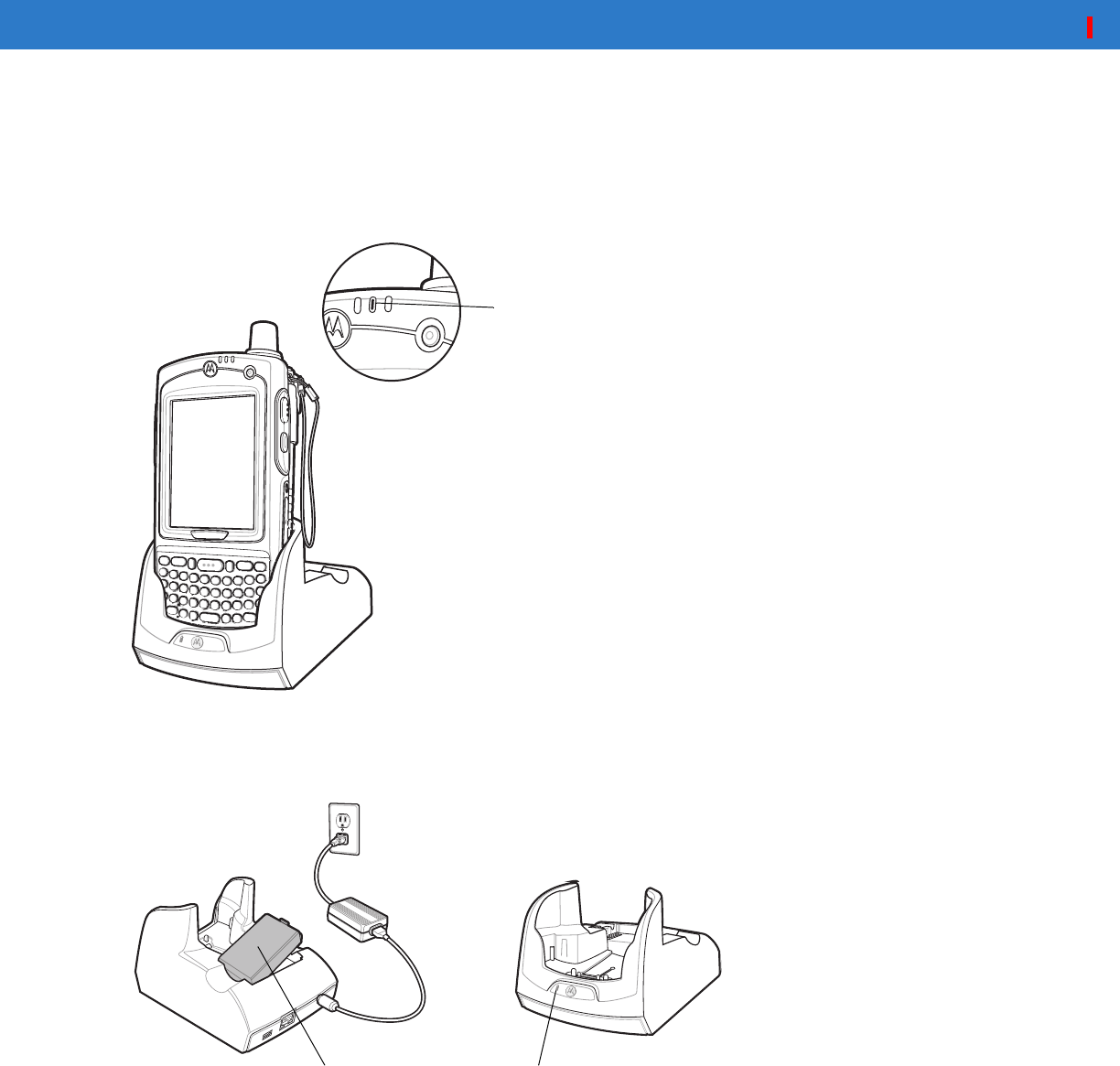
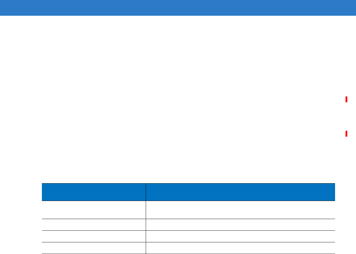
Charging the MC55 Battery
Connect the cradle to power. Insert the MC55 into the slot to begin charging.
Figure 6-1
MC55 Battery Charging
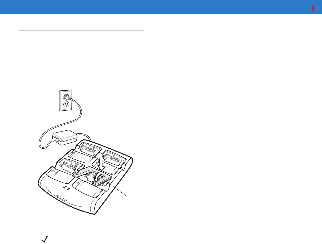
Charging the Spare Battery
Figure 6-2
Spare Battery Charging
Battery Charging Indicators
The Single Slot USB/Serial Cradle charges the MC55’s main battery and a spare battery simultaneously.
The MC55’s charge LED indicates the status of the battery charging in the MC55. See Table 1-2 on page 1-8 for
charging status indications.
Charging/Battery Status
LED
Spare Battery Spare Battery
Charging LED
DRAFT

Accessories 6 - 3
The spare battery charging LED on the cradle indicates the status of the spare battery charging in the cradle. See
Table 6-1 for charging status indications.
The 2200 mAh battery fully charges in less than five hours and the 3300 mAh battery fully charges in less than
seven hours.
Charging Temperature
Charge batteries in temperatures from 0°C to 40°C (32°F to 104°F). Charging is intelligently controlled by the
MC55.
To accomplish this, for small periods of time, the MC55 or accessory alternately enables and disables battery
charging to keep the battery at acceptable temperatures. The MC55 or accessory indicates when charging is
disabled due to abnormal temperatures via its LED. See Table 1-2 on page 1-8 and Table 6-1.
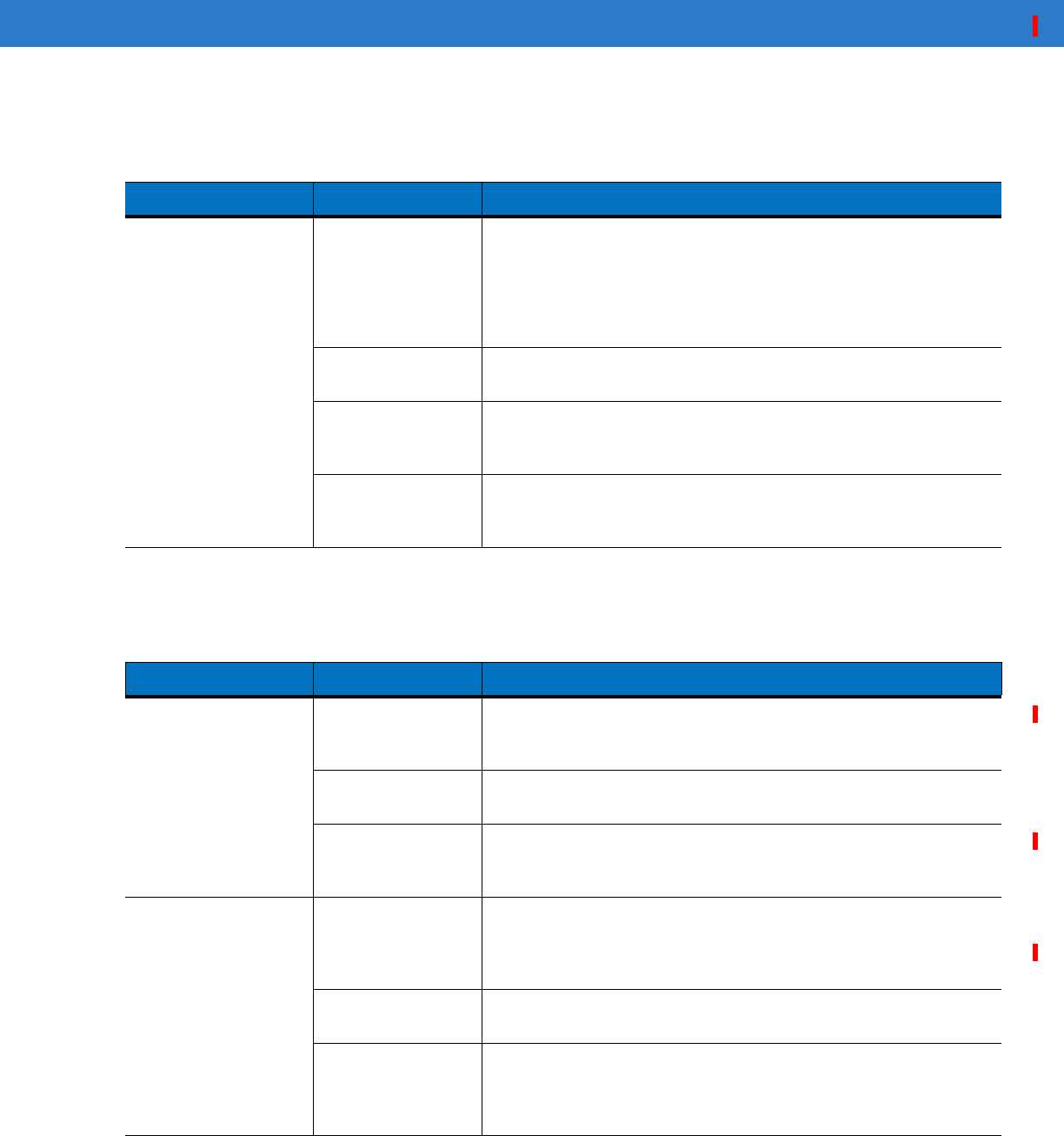
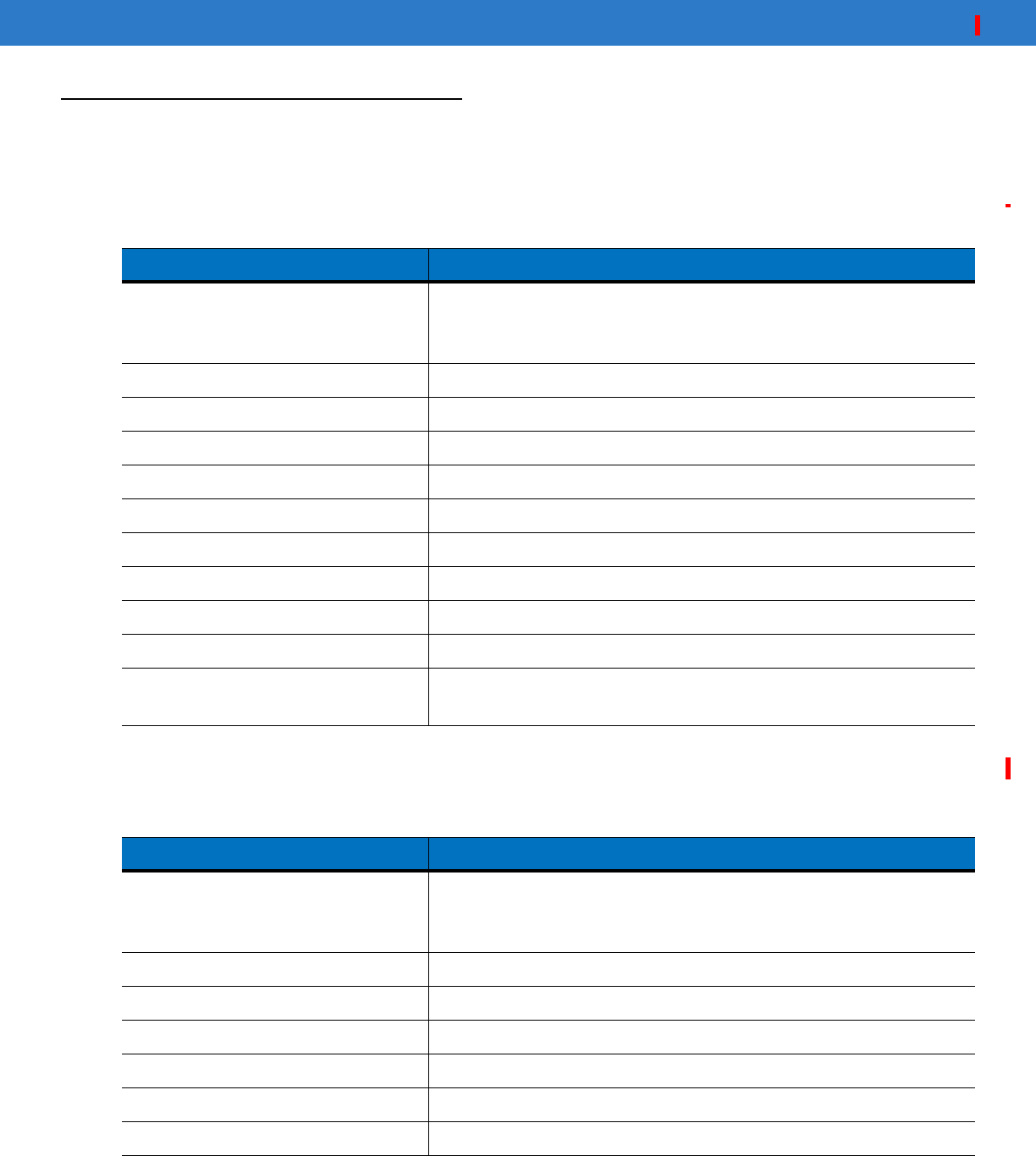
Table 6-1
Spare Battery LED Charging Indicators
Spare Battery LED
(on cradle) Indication
Off Battery is not charging; battery is not inserted correctly in the cradle;
cradle is not powered
Slow Blinking Amber Spare battery is charging.
Solid Amber Charging complete.
Fast Blinking Amber Charging error.
DRAFT
6 - 4 MC55 User Guide
22003300Four Slot Charge Only Cradle
This section describes how to set up and use a Four Slot Charge Only cradle with the MC55.
The Four Slot Charge Only cradle:
•
Provides 5.4 VDC power for operating the MC55.
•
Simultaneously charges up to four MC55 devices.
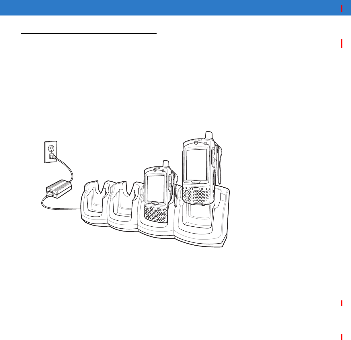
Charging
Insert the MC55 into a slot to begin charging.
Figure 6-3
MC55 Battery Charging
Battery Charging Indicators
The MC55’s charge LED shows the status of the battery charging in the MC55. See Table 1-2 on page 1-8 for
charging status indications.
The 2200 mAh battery fully charges in less than five hours and the 3300 mAh battery fully charges in less than
seven hours.
Charging Temperature
Charge batteries in temperatures from 0°C to 40°C (32°F to 104°F). Charging is intelligently controlled by the
MC55.
To accomplish this, for small periods of time, the MC55 or accessory alternately enables and disables battery
charging to keep the battery at acceptable temperatures. The MC55 or accessory indicates when charging is
disabled due to abnormal temperatures via its LED. See Table 1-2 on page 1-8.
DRAFT
Accessories 6 - 5
VCD5000 Vehicle Cradle
This section describes how to use a VCD5000 vehicle cradle with the MC55. For cradle installation and
communication setup procedures refer to the MC55 Integrator Guide.
Once installed in a vehicle, the cradle:
•
holds the MC55 securely in place
•
provides power for operating the MC55
•
re-charges the battery in the MC55
•
re-charges a spare battery.
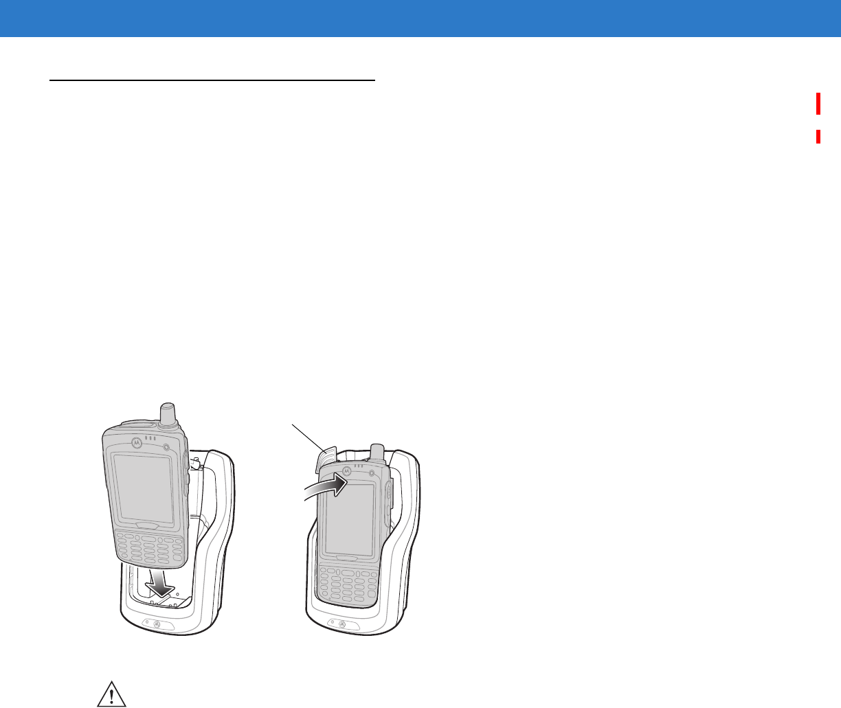
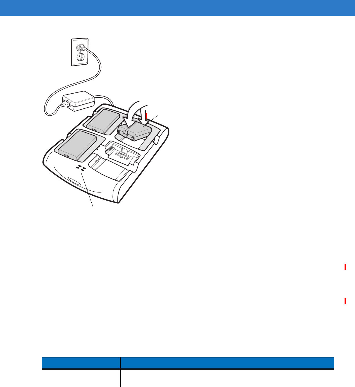
Charging the MC55 Battery
Insert the MC55 into the vehicle cradle to begin charging. A click indicates that the MC55 button release locking
mechanism is enabled and the MC55 is locked in place.
Figure 6-4
MC55 Battery Charging
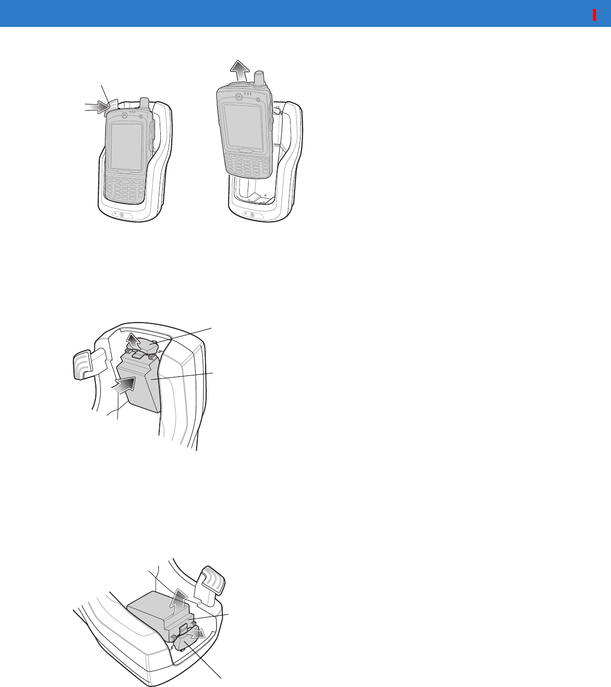
Removing the MC55
To remove the MC55, hold back the release lever on the cradle and pull the MC55 up and out of the cradle.
Release Lever
CAUTION Ensure the MC55 is fully inserted in the cradle. Lack of proper insertion may result in property damage
or personal injury. Motorola is not responsible for any loss resulting from the use of the products while
driving.
DRAFT
6 - 6 MC55 User Guide
Figure 6-5
Removing the MC55
Charging the Spare Battery
Insert a spare battery to begin charging:
1. Lift the battery release lever.
Figure 6-6
Inserting the Spare Battery
2. Insert the spare battery in the spare battery charging slot in the cradle with the charging contacts facing up and
to the rear of the cradle.
3. Release the battery release lever. The battery release lever locks the spare battery into place.
To remove a spare battery, hold back the battery release lever and lift the battery from the spare battery slot.
Figure 6-7
Removing the Spare Battery
Release Lever
Battery
Battery Release Lever
Battery Release Lever
Battery
DRAFT
Accessories 6 - 7
Battery Charging Indicators
The Vehicle Cradle charges the MC55’s main battery and a spare battery simultaneously.
The MC55’s charge LED indicates the status of the battery charging in the MC55. See Table 1-2 on page 1-8 for
charging status indications.
The spare battery charging LED on the cradle indicates the status of the spare battery charging in the cradle. See
Table 6-2 for charging status indications.
The 2200 mAh battery fully charges in less than five hours and the 3300 mAh battery fully charges in less than
seven hours.
Charging Temperature
Charge batteries in temperatures from 0°C to 40°C (32°F to 104°F). Charging is intelligently controlled by the
MC55.
To accomplish this, for small periods of time, the MC55 or accessory alternately enables and disables battery
charging to keep the battery at acceptable temperatures. The MC55 or accessory indicates when charging is
disabled due to abnormal temperatures via its LED. See Table 1-2 on page 1-8 and Table 6-2.
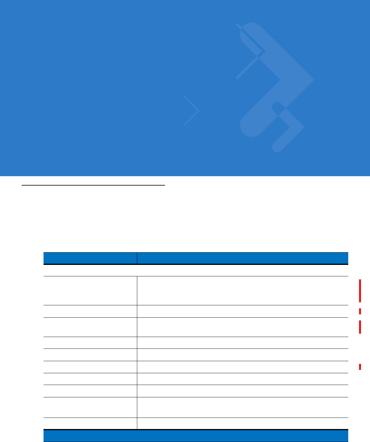
Table 6-2
Vehicle Cradle Spare Battery LED Charging Indicators
Spare Battery LED
(on cradle) Indication
Off Battery is not charging; battery is not inserted correctly in the cradle;
cradle is not powered
Slow Blinking Amber Spare battery is charging.
Solid Amber Charging complete.
Fast Blinking Amber Charging error.
DRAFT
6 - 8 MC55 User Guide
Four Slot Battery Charger
This section describes how to use the Four Slot Battery Charger to charge up to four MC55 batteries.
MC55 Battery Shim Installation
Before charging a battery, snap the MC55 shim into the battery slot as shown in Figure 6-9.
Figure 6-8
MC55 Battery Shim Installation
Battery Charging
1. Connect the charger to a power source.
2. Insert the battery into a battery charging well and gently press down on the battery to ensure proper contact.
Shim
NOTE To purchase additional shims, contact your local account manager or Motorola, Inc. Part number:
KT-76490-01R.
DRAFT
Accessories 6 - 9
Figure 6-9
Four Slot Battery Charger
Battery Charging Indicators
The charger has an amber LED for each battery charging well. See Table 6-3 for charging status indications. The
2200 mAh battery fully charges in less than five hours and the 3300 mAh battery fully charges in less than seven
hours.
Charging Temperature
Charge batteries in temperatures from 0°C to 40°C (32°F to 104°F). Charging is intelligently controlled by the
MC55.
To accomplish this, for small periods of time, the charger alternately enables and disables battery charging to keep
the battery at acceptable temperatures. The charger indicates when charging is disabled due to abnormal
temperatures via its LED. See Table 6-3.
Battery Charging
LEDs (4)
Battery
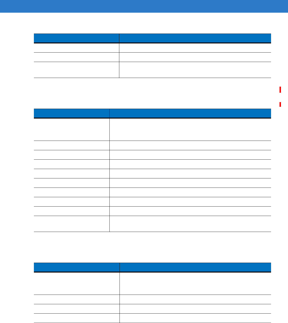
Table 6-3
Battery LED Charging Indicators
LED Indication
Off No battery in slot; battery is not charging; battery is not inserted correctly in the
charger; charger is not powered.
DRAFT

6 - 10 MC55 User Guide
Slow Blinking Amber Battery is charging.
Solid Amber Charging complete.
Fast Blinking Amber Charging error.
Table 6-3
Battery LED Charging Indicators (Continued)
LED Indication
DRAFT
Accessories 6 - 11
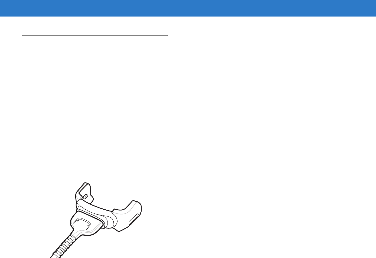
Magnetic Stripe Reader (MSR)
This section describes how to set up and use the snap-on MSR with the MC55. The MSR snaps on to the bottom
of the MC55 and removes easily when not in use.
When attached to the MC55, the MSR allows the MC55 to capture data from magnetic stripe cards. To download
MSR data capture software, visit the Support Central web site.
Attaching and Removing the MSR
To attach, slide the MSR onto the bottom of the MC55 and secure by snapping the arms into the MC55 housing.
Figure 6-10
MSR Installation
To remove the MSR open the arms and pull the MSR from the MC55.
Using the MSR
Install an MSR enabled application onto the MC55.
To use the MSR:
1. Attach the MSR to the MC55.
2. Power on the MC55.
3. Launch the MSR application.
4. Swipe the magnetic stripe card through the MSR, with the magnetic stripe on the card facing down. Swipe the
card in either direction, from left to right or from right to left. For best results, gently press down on the card
while swiping to ensure contact with the bottom of the reader.
NOTE When attaching a cable with a cup connector through the MSR to charge the device, you cannot swipe
cards.
DRAFT
6 - 12 MC55 User Guide
Figure 6-11
Magnetic Stripe Card Swiping
5. The application indicates if the data has been read correctly.
DRAFT
Accessories 6 - 13
Cables
This section describes how to set up and use the cables. The cables are available with a variety of connection
capabilities.
The following communication/charge cables are available:
•
Serial (RS232) Charge cable (9-pin D female with power input receptacle)
•
USB Client Charge cable (standard-A connector and a barrel receptacle for power)
•
Auto charge cable
•
DEX cable
•
Modem inverter cable.
The following printer cables are available directly from the printer manufacturer:
•
O’Neil Printer cable
•
Zebra Printer cable.
Figure 6-12
Cables
Communication/charge cables:
•
Provide the MC55 with operating and charging power when used with the Motorola approved power supply.
•
Synchronize information between the MC55 and a host computer. With customized or third party software, it
can also synchronize the MC55 with corporate databases.
•
Provide serial connection through the serial pass-through port for communication with a serial device, such
as a host computer. For communication setup procedures, refer to the MC55 Integrator Guide.
•
Provide USB connection through the USB pass-through port for communication with a USB device, such as
a host computer. For communication setup procedures, refer to the MC55 Integrator Guide.
Dedicated printer cables provide communication with a printer.
Battery Charging and Operating Power
The communication/charge cables can charge the MC55 battery and supply operating power.
To charge the MC55 battery:
1. Connect the communication/charge cable power input connector to the Motorola approved power source.
DRAFT

6 - 14 MC55 User Guide
2. Slide the bottom of the MC55 into the connector end of the communication/charge cable and gently press in
until it latches into the MC55. The MC55 amber Charge LED indicates the MC55 battery charging status. The
2200 mAh standard battery charges in less than five hours and the 3300 mAh standard battery charges in less
than seven hours. See Table 1-2 on page 1-8 for charging status indications.
3. When charging is complete, remove the cable by gently pulling the MC55 and the cable apart.
LED Charge Indications
The amber Charge LED on the MC55 indicates battery charging status. See Table 1-2 on page 1-8 for charging
status indications.
Charging Temperature
Charge batteries in temperatures from 0°C to 40°C (32°F to 104°F). Charging is intelligently controlled by the
MC55.
To accomplish this, for small periods of time, the MC55 or accessory alternately enables and disables battery
charging to keep the battery at acceptable temperatures. The MC55 or accessory indicates when charging is
disabled due to abnormal temperatures via its LED. See Table 1-2 on page 1-8.
DRAFT
Accessories 6 - 15
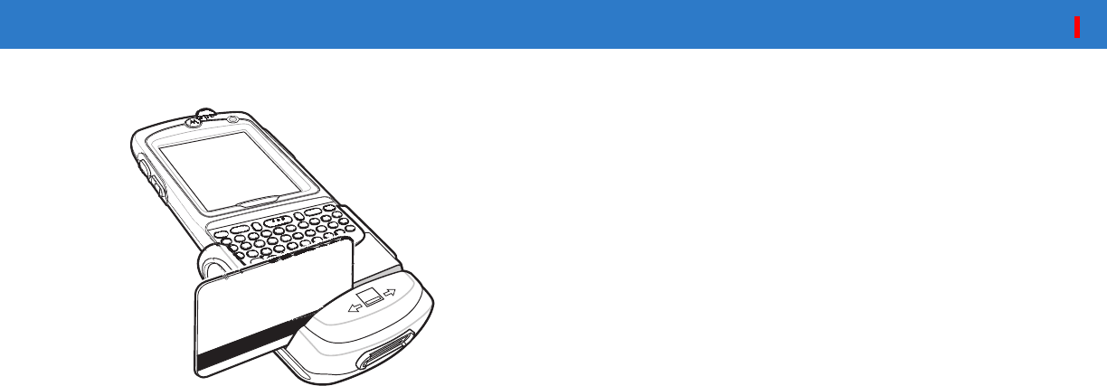
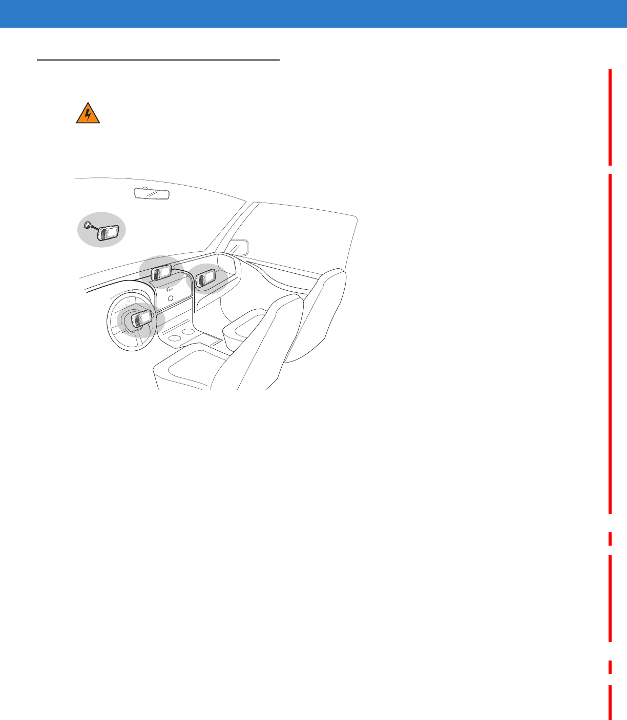
Vehicle Holder
Installation Reminders
Figure 6-13
Vechile Holder Mounting
•
Do not mount the vehicle holder where it will obscure the driver’s view of the road.
•
Do not mount the vehicle holder near the driver seat air bag deployment area.
•
Do not place the MC55 on top of the dashboard or anywhere without securing it in the vehicle holder.
•
Do not mount the vehicle holder near the passenger seat air bag deployment area.
•
Install the vehicle holder on the surface of your vehicle that is reasonably flat and free of dirt and oil.
Device Mounting Precautions
•
Some countries prohibit the mounting of any electronic device in any location on the vehicle dashboard. Be
sure to check your local laws acceptable mounting areas before installing the vehicle holder.
•
The heating and cooling cycle of a vehicle’s interior will in some cases loosen the adhesion of the suction
cup. Check the vacuum seal of the vehicle mount kit for adequate adhesion each time you use the unit, and
reinstall if necessary.
•
If the vehicle holder has problems staying on, clean the plastic suction cup with alcohol, then reinstall.
Installation
Install the vehicle mount on the surface of your vehicle that is reasonably flat and free of dirt and oil. Clean the
mounting surface with a glass cleaner and a clean cotton cloth. Install the vehicle mount on the windshield or other
flat car surface.
WARNING!Some countries prohibit the mounting of any electronic device in any location on the vehicle
dashboard. Be sure to check your local laws acceptable mounting areas before installing the
auto mounting kit.
DRAFT
6 - 16 MC55 User Guide
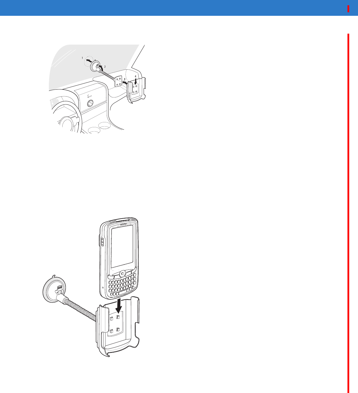
1. Fix the suction cup mount to the selected area with the suction lever facing up.
Figure 6-14
Assembly Vehicle Holder
2. Flip the lever down to create a vacuum between the suction cup and the mounting surface.
3. Make sure that the suction bond is strong enough before proceeding to the next step.
4. Insert the vehicle holder’s cradle plate to the holes on the back of the cradle.
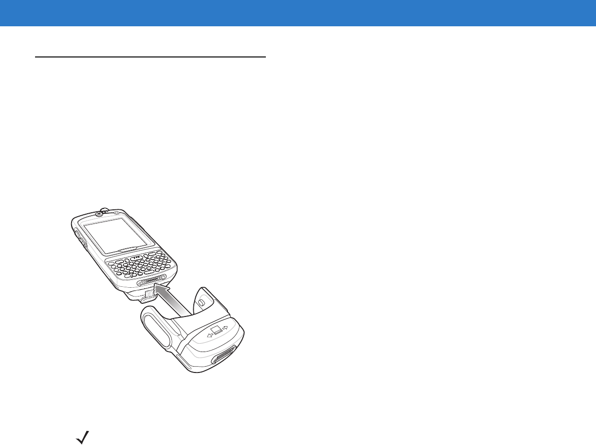
5. Move the car cradle until both parts are engaged.
6. Slide the MC55 into the cradle.
Figure 6-15
Insert MC55 into Vehicle Holder
7. Connect the auto charger cable to the MC55 and connect the other end to the cigarette lighter socket.
The LED indicator on the right side of the touch screen lights up orange during charging.
DRAFT

Accessories 6 - 17
DRAFT

6 - 18 MC55 User Guide
DRAFT

Chapter 7 Maintenance & Troubleshooting
Introduction
This chapter includes instructions on cleaning and storing the MC55, and provides troubleshooting solutions for
potential problems during MC55 operation.
Maintaining the MC55
For trouble-free service, observe the following tips when using the MC55:
•
Do not scratch the screen of the MC55. When working with the MC55, use the supplied stylus or
plastic-tipped pens intended for use with a touch-sensitive screen. Never use an actual pen or pencil or other
sharp object on the surface of the MC55 screen.
Motorola recommends using a screen protector, p/n KT-67525-01R.
•
The touch-sensitive screen of the MC55 is glass. Do not to drop the MC55 or subject it to strong impact.
•
Protect the MC55 from temperature extremes. Do not leave it on the dashboard of a car on a hot day, and
keep it away from heat sources.
•
Do not store or use the MC55 in any location that is dusty, damp, or wet.
•
Use a soft lens cloth to clean the MC55. If the surface of the MC55 screen becomes soiled, clean it with a soft
cloth moistened with a diluted window-cleaning solution.
•
Periodically replace the rechargeable battery to ensure maximum battery life and product performance.
Battery life depends on individual usage patterns.
DRAFT

7 - 2 MC55 User Guide
•
A screen protector is applied to the MC55. Motorola recommends using this to minimize wear and tear.
Screen protectors enhance the usability and durability of touch screen displays. Benefits include:
•Protection from scratches and gouges
•Durable writing and touch surface with tactile feel
•Abrasion and chemical resistance
•Glare reduction
•Keeping the device’s screen looking new
•Quick and easy installation.
Battery Safety Guidelines
•
The area in which the units are charged should be clear of debris and combustible materials or chemicals.
Particular care should be taken where the device is charged in a non commercial environment.
•
Follow battery usage, storage, and charging guidelines found in the user's guide.
•
Improper battery use may result in a fire, explosion, or other hazard.
•
To charge the mobile device battery, the battery and charger temperatures must be between +32 ºF and
+104 ºF (0 ºC and +40 ºC)
•
Do not use incompatible batteries and chargers. Use of an incompatible battery or charger may present a risk
of fire, explosion, leakage, or other hazard. If you have any questions about the compatibility of a battery or a
charger, contact Motorola Enterprise Mobility support.
•
For devices that utilize a USB port as a charging source, the device shall only be connected to products that
bear the USB-IF logo or have completed the USB-IF compliance program.
•
To enable authentication of an approved battery, as required by IEEE1725 clause 10.2.1, all batteries will
carry a Motorola hologram. Do not fit any battery without checking it has the Motorola authentication
hologram.
•
Do not disassemble or open, crush, bend or deform, puncture, or shred.
•
Severe impact from dropping any battery-operated device on a hard surface could cause the battery to
overheat.
•
Do not short circuit a battery or allow metallic or conductive objects to contact the battery terminals.
•
Do not modify or remanufacture, attempt to insert foreign objects into the battery, immerse or expose to water
or other liquids, or expose to fire, explosion, or other hazard.
•
Do not leave or store the equipment in or near areas that might get very hot, such as in a parked vehicle or
near a radiator or other heat source. Do not place battery into a microwave oven or dryer.
•
Battery usage by children should be supervised.
•
Please follow local regulations to promptly dispose of used re-chargeable batteries.
•
Do not dispose of batteries in fire.
•
Seek medical advice immediately if a battery has been swallowed.
•
In the event of a battery leak, do not allow the liquid to come in contact with the skin or eyes. If contact has
been made, wash the affected area with large amounts of water and seek medical advice.
•
If you suspect damage to your equipment or battery, contact Motorola Enterprise Mobility support to arrange
for inspection.
DRAFT

Maintenance & Troubleshooting 7 - 3
Cleaning
Materials Required
•
Alcohol wipes
•
Lens tissue
•
Cotton tipped applicators
•
Isopropyl alcohol
•
Can of compressed air with a tube.
Cleaning the MC55
Housing
Using the alcohol wipes, wipe the housing including keys and in-between keys.
Display
The display can be wiped down with the alcohol wipes, but care should be taken not to allow any pooling of liquid
around the edges of the display. Immediately dried the display with a soft, non-abrasive cloth to prevent streaking.
Scanner Exit Window
Wipe the scanner exit window periodically with a lens tissue or other material suitable for cleaning optical material
such as eyeglasses.
Connector
1. Remove the main battery from mobile computer. See Replacing the Main Battery on page 1-12.
2. Close battery door.
3. Dip the cotton portion of the cotton tipped applicator in isopropyl alcohol.
4. Rub the cotton portion of the cotton tipped applicator back-and-forth across the connector on the bottom of the
MC55. Do not leave any cotton residue on the connector.
5. Repeat at least three times.
6. Use the cotton tipped applicator dipped in alcohol to remove any grease and dirt near the connector area.
7. Use a dry cotton tipped applicator and repeat steps 4 through 6.
CAUTION Always wear eye protection.
Read warning label on compressed air and alcohol product before using.
If you have to use any other solution for medical reasons please contact Motorola for more information.
WARNING!Avoid exposing this product to contact with hot oil or other flammable liquids. If such exposure
occurs, unplug the device and clean the product immediately in accordance with these guidelines.
DRAFT
7 - 4 MC55 User Guide
8. Spray compressed air on the connector area by pointing the tube/nozzle about ½ inch away from the surface.
CAUTION: Do not point nozzle at yourself and others, ensure the nozzle or tube is away from your face.
9. Inspect the area for any grease or dirt, repeat if required.
Cleaning Cradle Connectors
To clean the connectors on a cradle:
1. Remove the DC power cable from the cradle.
2. Dip the cotton portion of the cotton tipped applicator in isopropyl alcohol.
3. Rub the cotton portion of the cotton tipped applicator along the pins of the connector. Slowly move the
applicator back-and-forth from one side of the connector to the other. Do not let any cotton residue on the
connector.
4. All sides of the connector should also be rubbed with the cotton tipped applicator.
5. Spray compressed air in the connector area by pointing the tube/nozzle about ½ inch away from the surface.
CAUTION: do not point nozzle at yourself and others, ensure the nozzle or tube is pointed away from your
face.
6. Ensure that there is no lint left by the cotton tipped applicator, remove lint if found.
7. If grease and other dirt can be found on other areas of the cradle, use lint free cloth and alcohol to remove.
8. Allow at least 10 to 30 minutes (depending on ambient temperature and humidity) for the alcohol to air dry
before applying power to cradle.
If the temperature is low and humidity is high, longer drying time is required. Warm temperature and dry
humidity requires less drying time.
Cleaning Frequency
The cleaning frequency is up to the customer’s discretion due to the varied environments in which the mobile
devices are used. They may be cleaned as frequently as required. However when used in dirty environments it
may be advisable to periodically clean the scanner exit window to ensure optimum scanning performance.
Troubleshooting
MC55
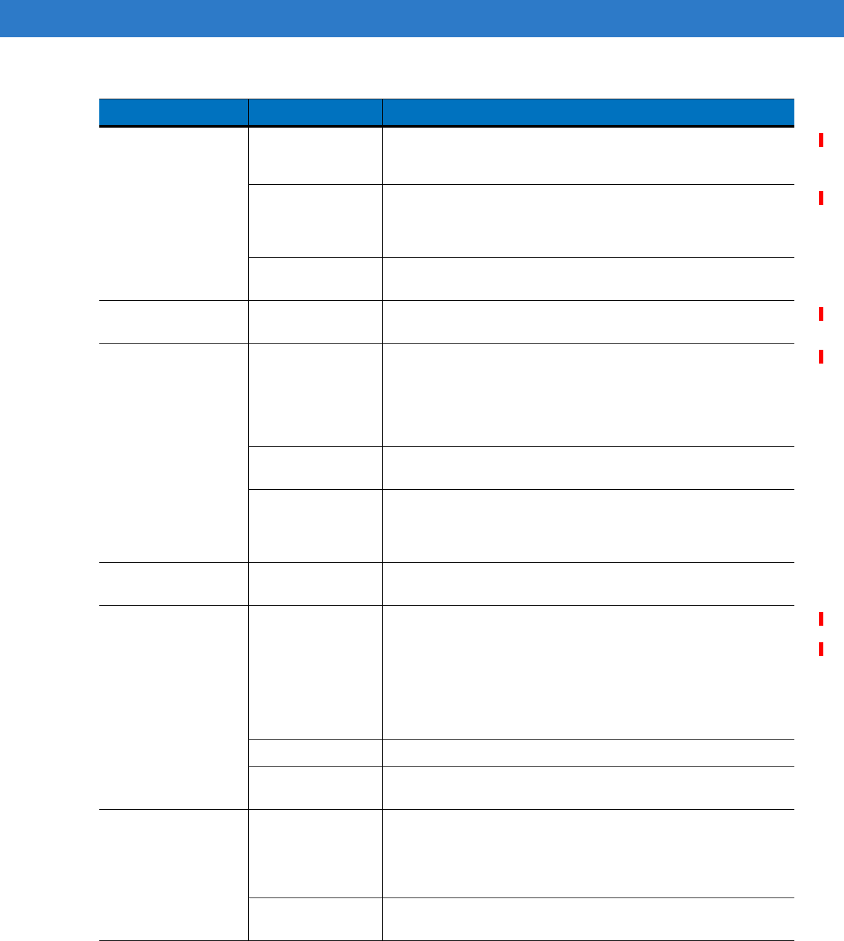
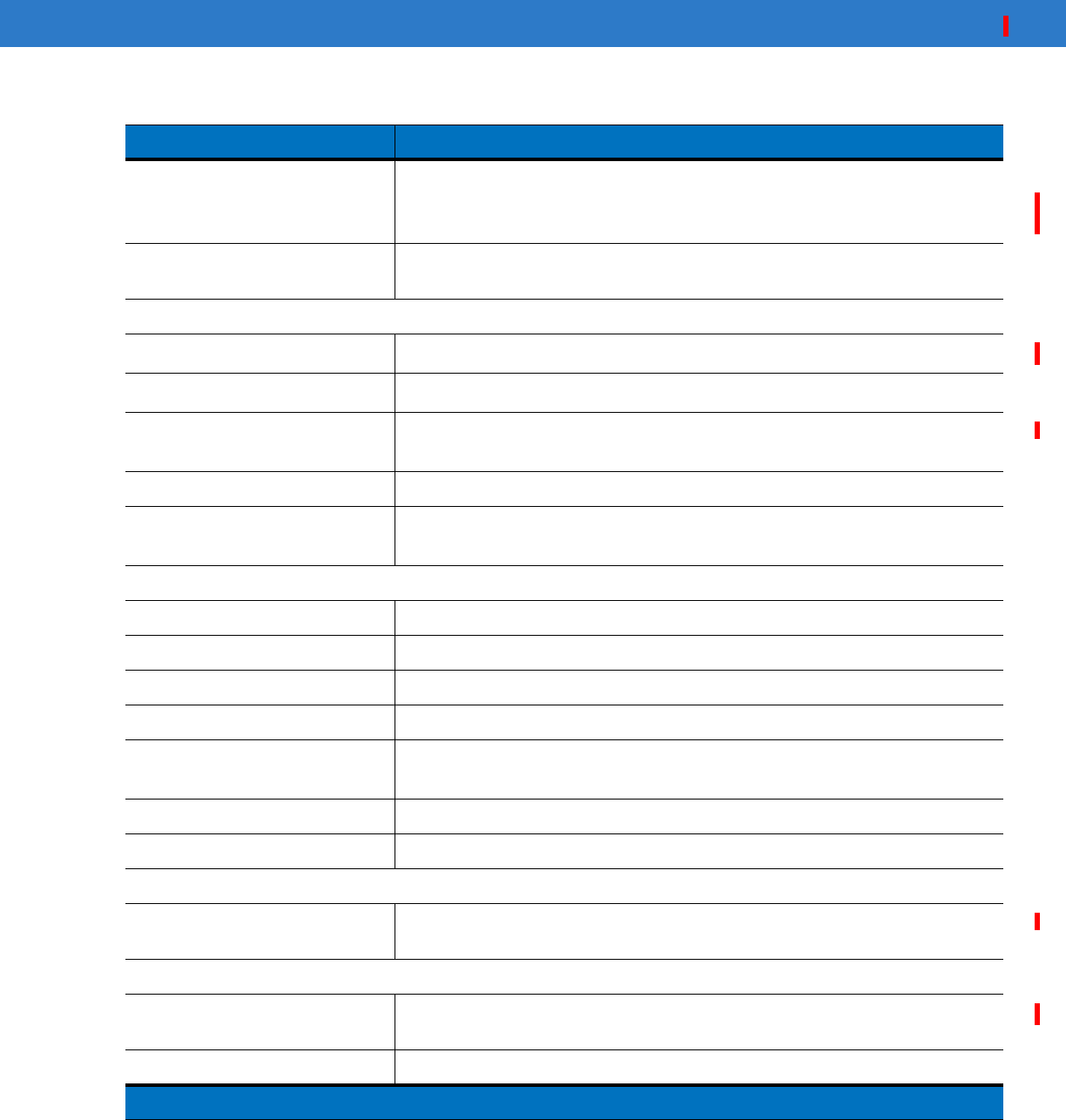
Table 7-1
Troubleshooting the MC55
Problem Cause Solution
MC55 does not turn
on. Lithium-ion battery
not charged. Charge or replace the lithium-ion battery in the MC55.
Lithium-ion battery
not installed
properly.
Install the battery properly. See Installing the Main Battery on page
1-6.
System crash. Perform a warm boot. If the MC55 still does not turn on, perform a
cold boot. See Resetting the MC55 on page 2-13.
DRAFT
Maintenance & Troubleshooting 7 - 5
Rechargeable
lithium-ion battery did
not charge.
Battery failed. Replace battery. If the MC55 still does not operate, perform a
warm boot, then a cold boot. See Resetting the MC55 on page
2-13.
MC55 removed
from cradle while
battery was
charging.
Insert MC55 in cradle. The 3600 mAh battery fully charges in less
than six hours.
Extreme battery
temperature. Battery does not charge if ambient temperature is below 0°C
(32°F) or above 40°C (104°F).
Cannot see
characters on display. MC55 not powered
on. Press the Power button.
During data
communication, no
data transmitted, or
transmitted data was
incomplete.
MC55 removed
from cradle or
disconnected from
host computer
during
communication.
Replace the MC55 in the cradle, or reattach the communication
cable and re-transmit.
Incorrect cable
configuration. See the system administrator.
Communication
software was
incorrectly installed
or configured.
Perform setup. Refer to the MC55 Integrator Guide for details.
No sound. Volume setting is
low or turned off. Adjust the volume. See Adjusting Volume on page 2-9.
MC55 shuts off. MC55 is inactive. The MC55 turns off after a period of inactivity. If the MC55 is
running on battery power, set this period from 1 to 5 minutes, in
one-minute intervals. If the MC55 is running on external power, set
this period to 1, 2, 5, 10, 15, or 30 minutes.
Check the Power window by selecting Start > Settings > System
tab and tapping the Power icon. Select the Advanced tab and
change the setting for a longer delay before the automatic shutoff
feature activates.
Battery is depleted. Replace the battery.
Battery is not
inserted properly. Insert the battery properly. See Installing the Main Battery on page
1-6.
Tapping the window
buttons or icons does
not activate the
corresponding
feature.
Screen is not
calibrated correctly. Re-calibrate the screen. See Calibrating the Screen on page 1-9.
The system is not
responding. Warm boot the system. See Resetting the MC55 on page 2-13.
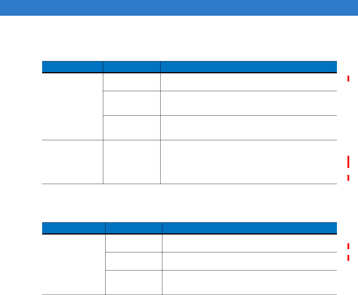
Table 7-1
Troubleshooting the MC55 (Continued)
Problem Cause Solution
DRAFT

7 - 6 MC55 User Guide
A message appears
stating that the MC55
memory is full.
Too many files
stored on the
MC55.
Delete unused memos and records. If necessary, save these
records on the host computer (or use an SD card for additional
memory).
Too many
applications
installed on the
MC55.
Remove user-installed applications on the MC55 to recover
memory. Select Start > Settings > System tab and tap the Remove
Programs icon. Select the unused program and tap Remove.
MC55 keeps powering
down to protect
memory contents.
The MC55’s battery
is low. Recharge the battery.
The internal
Bluetooth radio is
powered on for a
long time.
Because this mode requires battery power, power it off when not
needed. Using the SetDeviceState() API (refer to the SMDK Help
File), set the Bluetooth to D4 power state.
The MC55 does not
accept scan input. Scanning
application is not
loaded.
Load a scanning application on the MC55. See the system
administrator.
Unreadable bar
code. Ensure the symbol is not defaced.
Distance between
exit window and bar
code is incorrect.
Place the MC55 within proper scanning range.
MC55 is not
programmed for the
bar code.
Program the MC55 to accept the type of bar code being scanned.
MC55 is not
programmed to
generate a beep.
If the MC55 does not beep on a good decode, set the application
to generate a beep on good decode.
Battery is low. If the scanner stops emitting a laser beam upon a trigger press,
check the battery level. When the battery is low, the scanner shuts
off before the MC55 low battery condition notification.
Note: If the scanner is still not reading symbols, contact the
distributor or Motorola.
Table 7-1
Troubleshooting the MC55 (Continued)
Problem Cause Solution
DRAFT
Maintenance & Troubleshooting 7 - 7
Bluetooth Connection
Single Slot USB/Serial Cradle
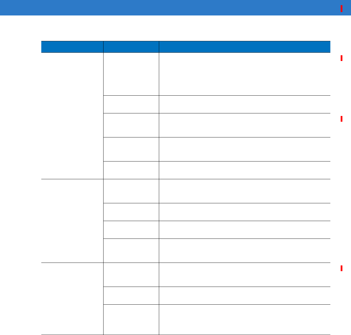
Table 7-2
Troubleshooting Bluetooth Connection
Problem Cause Solution
MC55 cannot find
any Bluetooth
devices nearby.
Too far from other
Bluetooth devices. Move closer to the other Bluetooth device(s), within a range of 10
meters.
The Bluetooth
device(s) nearby
are not turned on.
Turn on the Bluetooth device(s) to find.
The Bluetooth
device(s) are not in
discoverable mode.
Set the Bluetooth device(s) to discoverable mode. If needed, refer
to the device’s user documentation for help.
When trying to
connect a Bluetooth
phone and MC55, the
phone thinks a
previously paired
MC55 is used.
The phone
remembers the
name and address
of the MC55 it last
paired with via the
Bluetooth radio.
Manually delete the pairing device and name from the phone. Refer
to the phone’s user documentation for instructions.
Table 7-3
Troubleshooting the Single Slot USB/Serial Cradle
Symptom Possible Cause Action
LEDs do not light
when MC55 or spare
battery is inserted.
Cradle is not
receiving power. Ensure the power cable is connected securely to both the cradle
and to AC power.
MC55 is not seated
firmly in the cradle. Remove and re-insert the MC55 into the cradle, ensuring it is firmly
seated.
Spare battery is not
seated firmly in the
cradle.
Remove and re-insert the spare battery into the charging slot,
ensuring it is firmly seated.
DRAFT
7 - 8 MC55 User Guide
MC55 battery is not
charging. MC55 was
removed from
cradle or cradle
was unplugged
from AC power too
soon.
Ensure cradle is receiving power. Ensure MC55 is seated
correctly. Confirm main battery is charging under Start > Settings
> System > Power. The 3600 mAh battery fully charges in less than
six hours.
Battery is faulty. Verify that other batteries charge properly. If so, replace the faulty
battery.
The MC55 is not
fully seated in the
cradle.
Remove and re-insert the MC55 into the cradle, ensuring it is firmly
seated.
Ambient
temperature of the
cradle is too warm.
Move the cradle to an area where the ambient temperature is
between 0°C (32°F) and 35°C (95°F).
Extreme battery
temperature. Battery does not charge if ambient temperature is below 0°C
(32°F) or above 40°C (104°F).
Spare battery is not
charging. Battery not fully
seated in charging
slot.
Remove and re-insert the spare battery in the cradle, ensuring it is
firmly seated.
Battery inserted
incorrectly. Re-insert the battery so the charging contacts on the battery align
with the contacts on the cradle.
Battery is faulty. Verify that other batteries charge properly. If so, replace the faulty
battery.
Ambient
temperature of the
cradle is too warm.
Move the cradle to an area where the ambient temperature is
between 0°C (32°F) and 35°C (95°F).
During data
communication, no
data transmits, or
transmitted data was
incomplete.
MC55 removed
from cradle during
communications.
Replace MC55 in cradle and retransmit.
Incorrect cable
configuration. See the system administrator.
Communication
software is not
installed or
configured properly.
Perform setup as described in the MC55 Integrator Guide.
Table 7-3
Troubleshooting the Single Slot USB/Serial Cradle (Continued)
Symptom Possible Cause Action
DRAFT

Maintenance & Troubleshooting 7 - 9
Vehicle Cradle
Table 7-4
Troubleshooting the Vehicle Cradle
Symptom Possible Cause Action
MC55 battery
charging LED does
not light up.
Cradle is not
receiving power. Ensure the power input cable is securely connected to the cradle’s
power port.
MC55 battery is not
recharging. MC55 was
removed from the
cradle too soon.
Replace the MC55 in the cradle. The 3600 mAh battery fully
charges in less than six hours.
Battery is faulty. Replace the battery.
MC55 is not placed
correctly in the
cradle.
Remove the MC55 from the cradle, and re-insert correctly. If the
battery still does not charge, contact customer support.
The MC55 battery charging LED slowly blinks amber when the
MC55 is correctly inserted and charging.
Ambient
temperature of the
cradle is too warm.
Move to an area where the ambient temperature is between 0oC
and 35oC.
No data transmitted,
or transmitted data
was incomplete.
MC55 removed
from cradle during
communication.
Replace MC55 in cradle and retransmit.
No null modem
cable was used. Some external devices require a null modem cable. Retransmit
using a null modem cable.
Incorrect cable
configuration. See the system administrator.
Cable missing or
disconnected. Re-connect cable.
DRAFT
7 - 10 MC55 User Guide
Four Slot Battery Charger
r
Cables
Table 7-5
Troubleshooting The Four Slot Battery Charger
Symptom Possible Cause Action
Battery not charging. Battery was
removed from the
charger or charger
was unplugged
from AC power too
soon.
Re-insert the battery in the charger or re-connect the charger’s
power supply. The 3600 mAh battery fully charges in less than six
hours.
Battery is faulty. Verify that other batteries charge properly. If so, replace the faulty
battery.
Battery contacts not
connected to
charger.
Verify that the battery is seated in the battery well correctly with the
contacts facing down.
Ambient
temperature of the
cradle is too warm.
Move the cradle to an area where the ambient temperature is
between 0oC and 35oC.
Table 7-6
Troubleshooting the Cables
Symptom Possible Cause Action
MC55 battery is not
charging. MC55 was
disconnected from
AC power too soon.
Connect the power cable correctly. Confirm main battery is
charging under Start > Settings > System > Power. The 3600 mAh
battery fully charges in less than six hours.
Battery is faulty. Verify that other batteries charge properly. If so, replace the faulty
battery.
The MC55 is not
fully attached to
power.
Detach and re-attach the power cable to the MC55, ensuring it is
firmly connected.
During data
communication, no
data transmits, or
transmitted data was
incomplete.
Cable was
disconnected from
MC55 during
communications.
Re-attach the cable and retransmit.
Incorrect cable
configuration. See the system administrator.
Communication
software is not
installed or
configured properly.
Perform setup as described in the MC55 Integrator Guide.
DRAFT

Maintenance & Troubleshooting 7 - 11
Magnetic Stripe Reader
Table 7-7
Troubleshooting the Magnetic Stripe Reader
Symptom Possible Cause Action
MSR cannot read
card. MSR removed from
MC55 during card
swipe.
Reattach MSR to MC55 and reswipe the card.
Faulty magnetic
stripe on card. See the system administrator.
MSR application is
not installed or
configured properly.
Ensure the MSR application is installed on the MC55.
Ensure the MSR application is configured correctly.
MC55 battery is not
charging. MC55 was
removed from MSR
or MSR was
unplugged from AC
power too soon.
Ensure MSR is receiving power. Ensure MC55 is attached
correctly. Confirm main battery is charging under Start > Settings
> System > Power. The 3600 mAh battery fully charges in less than
six hours.
Battery is faulty. Verify that other batteries charge properly. If so, replace the faulty
battery.
The MC55 is not
fully attached to the
MSR.
Detach and re-attach the MSR to the MC55, ensuring it is firmly
connected.
During data
communication, no
data transmits, or
transmitted data was
incomplete.
MC55 detached
from MSR during
communications.
Reattach MC55 to MSR and retransmit.
Incorrect cable
configuration. See the system administrator.
Communication
software is not
installed or
configured properly.
Perform setup as described in the MC55 Integrator Guide.
DRAFT

7 - 12 MC55 User Guide
DRAFT
Appendix A Technical Specifications
MC55 Technical Specifications
The following tables summarize the EDA’s intended operating environment and technical hardware specifications.
MC55 EDA
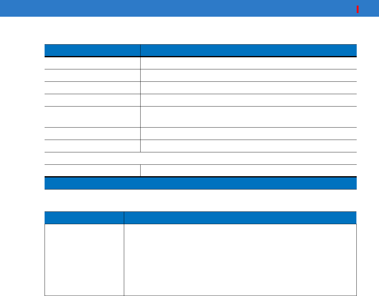
Table A-1
MC55 EDA Technical Specifications
Item Description
Physical Characteristics
Dimensions Length: TBS
Width: TBS
Depth: TBS
Weight (inc. standard battery) TBS
Display Transflective color 3.5” QVGA with backlight, TFT-LCD, 65K colors,
240 W x 320 L
Touch Panel Glass analog resistive touch
Backlight LED backlight
Main Battery Rechargeable Lithium Ion 3.7V, 2400 mAh Smart Battery
Backup Battery NiMH battery (rechargeable) 15 mAh 2.4V (not user-accessible)
Expansion Slot User accessible microSD slot (with secure cover).
Network Connections Ethernet (via cradle)
High-speed USB, host or client, Bluetooth
Notification Vibrator and audible alert
Note 1: Total output power can be either USB or serial or a combination of both that cannot exceed 200 mA.
DRAFT
A - 2 MC55 User Guide
Keypad Options 26 key numeric
44 key QWERTY, 44 key AZERTY, 44 key QWERTZ
PIM
Audio Speaker, receiver, microphone, headset jack, software support for full duplex
record and playback (stereo)
Performance Characteristics
CPU Intel
®
XScale™ Bulverde PXA270 processor at 520 MHz
Operating System Microsoft
®
Windows Mobile™ 6
Memory 64 MB RAM/128 MB FLASH
128MB RAM/256MB FLASH
Interface/Communications RS-232, USB 1.1
Output Power (Note 1) USB: 5 VDC @ 200 mA max.
Serial: 5 VDC @ 200 mA max.
User Environment
Operating Temperature -10°C to 50°C (14°F to 122°F)
Storage Temperature -20°C to 70°C (-4°F to 158°F)
Charging Temperature 32°F to 104°F / 0° C to 40° C
Humidity 95% non-condensing
Drop Specification 4 ft. drop to concrete, 6 drops per 6 sides over operating temperature range.
5 ft. drop to concrete, 2 drops per 6 sides at ambient temperature 23°C (73°F).
Electrostatic Discharge (ESD) +/-15kVdc air discharge, +/-8kVdc direct discharge, +/-8kVdc indirect discharge
Sealing IP54
Wireless WAN Data and Voice Communications
Wireless Wide Area Network
(WWAN) radios
MC5504 and MC5574:
GSM: HSDPA (850, 900, 1800 and 1900 MHz)
Wireless LAN Data and Voice Communications
Wireless Local Area Network
(WLAN) radio Tri-mode IEEE
®
802.11b/g
Data Rates Supported 1, 2, 5.5, 6, 9, 11, 12, 18, 24, 36, 48, and 54 Mbps
Table A-1
MC55 EDA Technical Specifications (Continued)
Item Description
Note 1: Total output power can be either USB or serial or a combination of both that cannot exceed 200 mA.
DRAFT

Using the Interfaces A - 3
Operating Channels Chan 8-169 (5040 – 5845 MHz) (4920 – 4980 MHz) Japan only
Chan 1-13 (2412-2472 MHz) Chan 14 (2484 MHz) Japan only
Actual operating frequencies depend on regulatory rules and certification
agency
Security WPA2, WPA, WEP (40 or 128 bit), TKIP, TLS, TTLS (MS-CHAP), TTLS
(MS-CHAP v2), TTLS (CHAP), TTLS-MD5, TTLS-PAP, PEAP-TLS, PEAP
(MS-CHAP v2), AES, LEAP
Spreading Technique Direct Sequence Spread Spectrum (DSSS) and Orthogonal Frequency Division
Multiplexing (OFDM)
Antenna Internal for WLAN, Bluetooth and GPS, WWAN
Voice Communication Integrated Voice-over-IP ready (P2P, PBX, PTT), Wi-Fi™-certified, IEEE 802.11
b/g direct sequence wireless LAN
Wireless PAN Data and Voice Communications
Bluetooth Class II, v 2.0 EDR; on-board chip antenna.
Data Capture Specifications
Options 2D imager, 1D linear, color camera
Linear 1D Scanner (SE950) Specifications
Optical Resolution 0.005 in. minimum element width
Roll +/- 30° from vertical
Pitch Angle +/- 65° from normal
Skew Tolerance +/- 60° from normal
Ambient Light Sunlight: 8,000 ft. candles (86,112 Lux)
Artificial Light: 450 ft. candles (4,844 Lux)
Shock 2,000 +/- 5% G
Scan Rate 50 (+/- 6) scans/sec (bidirectional)
Scan Angle 46.5° (typical)
Laser Power 1.0 mW nominal
2D Imager Engine (SE4400) Specifications
Field of View Horizontal - 32.2°
Vertical - 24.5°
Optical Resolution 640 H x 480 V pixels (gray scale)
Roll 360°
Table A-1
MC55 EDA Technical Specifications (Continued)
Item Description
Note 1: Total output power can be either USB or serial or a combination of both that cannot exceed 200 mA.
DRAFT
A - 4 MC55 User Guide
Pitch Angle +/- 60° from normal
Skew Tolerance +/- 50° from normal
Ambient Light Total darkness to 9,000 ft. candles (96,900 Lux)
Shock 2,000 +/- 5% G
Focal Distance from Front of
Engine Near: 5 inches
Far: 9 inches
Aiming Element (VLD) 650 nm +/- 5 nm
Illumination Element (LED) 635 nm +/- 20 nm
Camera Specifications
Resolution 2 Mega pixel with auto focus and flash
Table A-2
Data Capture Options
Item Description
Laser Decode Capability Code 39 Code 128 Code 93
Codabar Code 11 Discrete 2 of 5
Interleaved 2 of 5 EAN-8 EAN-13
MSI UPCA UPCE
UPC/EAN supplementals Coupon Code Trioptic 39
Webcode Chinese 2 of 5 GS1 DataBar
GS1 DataBar Truncated GS1 DataBar Limited GS1 DataBar Stacked
GS1 DataBar Expanded GS1 DataBar Expanded Stacked
GS1 DataBar Stacked Omni
Table A-1
MC55 EDA Technical Specifications (Continued)
Item Description
Note 1: Total output power can be either USB or serial or a combination of both that cannot exceed 200 mA.
DRAFT

Using the Interfaces A - 5
Imaging Decode Capability Code 39 Code 128 Code 93
Codabar Code 11 Interleaved 2 of 5
Discrete 2 of 5 MSI EAN-8
EAN-13 UPCA UPCE
UPC/EAN supplementals Coupon Code Trioptic 39
Webcode TLC39 Composite AB
Composite C Micro PDF-417 PDF-417
Macro PDF-417 (Macro) Micro PDF-417 QR Code
Data Matrix Maxi Code US Postnet*
US Planet UK 4-state Australian 4-state
Canadian 4-state Japanese 4-state Dutch Kix
Chinese 2 of 5 USPS 4-state (US4CB) Aztec
microQR GS1 DataBar
GS1 DataBar Truncated GS1 DataBar Limited GS1 DataBar Stacked
GS1 DataBar Expanded GS1 DataBar Expanded Stacked
GS1 DataBar Stacked Omni
Camera Decode Capability Code 39 Code 128 Code 93
Codabar Code 11 Interleaved 2 of 5
Discrete 2 of 5 MSI EAN-8
EAN-13 UPCA UPCE
UPC/EAN supplementals Coupon Code Trioptic 39
Webcode TLC39 Composite AB
Composite C Micro PDF-417 PDF-417
Macro PDF-417 (Macro) Micro PDF-417 QR Code
Data Matrix Maxi Code US Postnet*
US Planet UK 4-state Australian 4-state
Canadian 4-state Japanese 4-state Dutch Kix
GS1 DataBar
GS1 DataBar Truncated GS1 DataBar Limited GS1 DataBar Stacked
GS1 DataBar Expanded GS1 DataBar Expanded Stacked
GS1 DataBar Stacked Omni
Table A-2
Data Capture Options (Continued)
Item Description
DRAFT
A - 6 MC55 User Guide
MC55 Accessory Specifications
Single Slot USB/Serial Cradle
Four Slot Charge Only Cradle
Table A-3
Single Slot USB/Serial Cradle Technical Specifications
Feature Description
Dimensions Length: 10.92 cm (4.3 in.)
Width: 5.84 cm (2.3 in.)
Height: 8.13 cm (3.2 in.)
Weight 196 g (6.9 oz)
Input Power 12 VDC
Power Consumption 30 watts
Interface USB, Serial
Operating Temperature 0°C to 50°C (32°F to 122°F)
Storage Temperature -40°C to 70°C (-40°F to 158°F)
Charging Temperature 0°C to 40°C (32°F to 104°F)
Humidity 5% to 95% non-condensing
Drop 76.2 cm (30.0 in.) drops to vinyl tiled concrete at room temperature
Electrostatic Discharge (ESD) +/- 15 kV air
+/- 8 kV contact
Table A-4
Four Slot Charge Only Cradle Technical Specifications
Feature Description
Dimensions Length: 46.36 cm (18.25 in.)
Width: 11.13 cm (4.38 in.)
Height: 13.72 cm (5.40 in.)
Weight 1079 g (2.38 lb)
Input Power 12 VDC
Power Consumption 100 watts
Operating Temperature 0°C to 50°C (32°F to 122°F)
Storage Temperature -40°C to 70°C (-40°F to 158°F)
Charging Temperature 0°C to 40°C (32°F to 104°F)
DRAFT
Using the Interfaces A - 7
Four Slot Battery Charger
Magnetic Stripe Reader
Humidity 5% to 95% non-condensing
Drop 76.2 cm (30.0 in.) drops to vinyl tiled concrete at room temperature
Electrostatic Discharge (ESD) +/- 15 kV air
+/- 8 kV contact
Table A-4
Four Slot Charge Only Cradle Technical Specifications (Continued)
Feature Description
Table A-5
Four Slot Battery Charger Technical Specifications
Feature Description
Dimensions Length: 20.96 cm (8.25 in.)
Width: 15.24 cm (6.0 in.)
Height: 4.32 cm (1.7 in.)
Weight 386 g (13.6 oz)
Input Power 12 VDC
Power Consumption 30 watts
Operating Temperature 0°C to 50°C (32°F to 122°F)
Storage Temperature -40°C to 70°C (-40°F to 158°F)
Charging Temperature 0°C to 40°C (32°F to 104°F)
Humidity 5% to 95% non-condensing
Drop 76.2 cm (30.0 in.) drops to vinyl tiled concrete at room temperature
Electrostatic Discharge (ESD) +/- 15 kV air
+/- 8 kV contact
Table A-6
Magnetic Stripe Reader (MSR) Technical Specifications
Feature Description
Dimensions Length: 7.87 cm (3.1 in.)
Width: 8.38 cm (3.3 in.)
Height: 3.56 cm (1.4 in.)
Weight 48 g (1.7 oz)
Interface Serial with baud rate up to 19,200
Format ANSI, ISO, AAMVA, CA DMV, user-configurable generic format
DRAFT
A - 8 MC55 User Guide
Swipe Speed 5 to 50 in. (127 to 1270 mm) /sec, bi-directional
Decoders Generic, Raw Data
Mode Buffered, unbuffered
Track Reading Capabilities Tracks 1 and 3: 210 bpi
Track 2: 75 and 210 bpi, autodetect
Operating Temperature 0°C to 50°C (32°F to 122°F)
Storage Temperature -40°C to 70°C (-40°F to 158°F)
Humidity 5% to 95% non-condensing
Drop 1.22 m (4 ft.) drops to concrete
Electrostatic Discharge (ESD) +/- 15 kV air
+/- 8 kV contact
Table A-6
Magnetic Stripe Reader (MSR) Technical Specifications (Continued)
Feature Description
DRAFT

Appendix A Voice Quality Manager
Introduction
The Voice Quality Manager (VQM) is a software package that resides on the MC55. VQM enables a set of features
for Voice over WiFi (VoWiFi) calls, and a sub-set of those features for cellular line (GSM or CDMA) calls. The VQM
user interface is designed to be intuitive and easy to use, so complex tasks such as enabling the Acoustic Echo
Canceller (AEC) while a call is in progress are done with very little or no user intervention.
Features
The VQM software:
•
Improves the voice transmission quality without using additional battery power.
•
Turns on the AEC for VoWiFi calls automatically, without user intervention.
•
Prioritizes the outgoing audio IP packets.
•
Provides user-selectable audio modes (speakerphone and handset) with a single tap of the VQM icon. A
VQM icon in the title bar of the device indicates the audio mode currently in use.
•
NDIS 5.1 compliant.
Enabling VQM
To enable VQM:
1. Tap Start > Programs > File Explorer.
2. Navigate to the Windows folder.
3. Locate the file VQMAudioNotify.
4. Tap the filename to enable VQM.
DRAFT
A - 2 MC55 User Guide
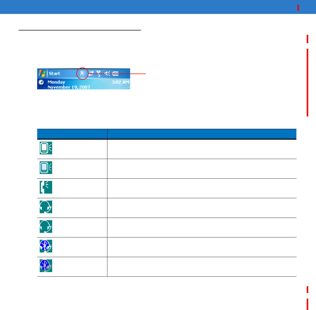
Audio Modes
The MC55 can be in any one of the seven different audio modes. The mode is visually indicated by the VQM icon
on the title bar.
Figure A-1
VQM Icon in Title Bar
The VQM icon indicates that the device is in speakerphone mode without Acoustic Echo Cancellation (indicated by
the gray VQM icon). The audio modes and their corresponding VQM title bar icons are:
Changing Audio Modes
Depending upon the audio mode being used, the mode can be changed by tapping the VQM icon in the title bar.
The audio mode can only be changed while the user is on a call.
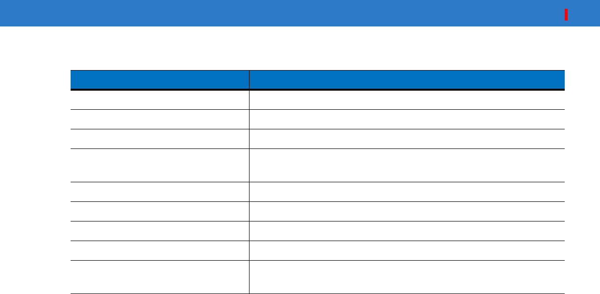
Table A-1
VQM Icons
Icon Description
Speakerphone with Acoustic Echo Cancellation.
Speakerphone without Acoustic Echo Cancellation.
Handset with Acoustic Echo Cancellation (device is in handset mode only while on
a call).
Headset while on a call (Acoustic Echo Cancellation is not enabled for wired or
Bluetooth headsets).
Headset while not on a call.
Bluetooth headset while on a call (Acoustic Echo Cancellation is not enabled for
wired or Bluetooth headsets). White icon.
Bluetooth headset while not on a call. Gray icon.
VQM icon
DRAFT
Using the Interfaces A - 3
The table below lists the current audio mode and the subsequent audio mode after tapping the VQM icon.
If the audio mode is set to speakerphone and the user taps the VQM icon, the audio mode changes to handset.
If the user is using a Bluetooth headset, tapping the VQM icon un-pairs the Bluetooth headset from the device
causing the audio to be routed to the default mode. In VQM 2.5, there is no way to go back to the Bluetooth
headset using the VQM icon if it is un-paired The only way to reconnect the Bluetooth headset to the device is by
using the BTExplorer application.
If the user taps the VQM icon when a wired headset is connected to the mobile device, the audio mode does not
change. The audio continues to get routed to the wired headset.
If the user taps the VQM icon while not on a call there is not change to the audio mode.
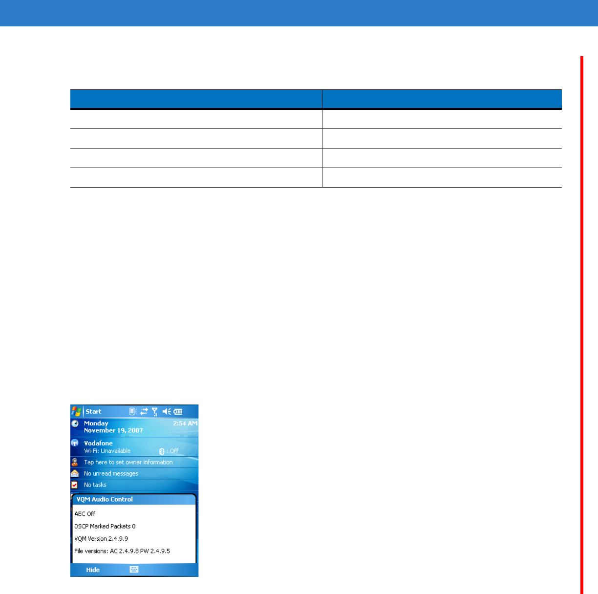
Tap and hold the VQM icon in the title bar to display a notification dialog box that contains:
•
AEC: The Acoustic Echo Canceller status
•
DSCP Marked Packets: The number of outbound voice packets that have been recognized and marked as
high priority by VQM.
•
VQM Version: The VQM version number.
Figure A-2
VQM Audio Control Dialog Box
Table A-2
Changing Audio Modes
Audio Mode before Tapping VQM Icon Audio Mode after Tapping VQM Icon
Speakerphone Handset
Handset Speakerphone
Wired headset Wired headset
Bluetooth headset Speakerphone
DRAFT

A - 4 MC55 User Guide
Voice Packet Prioritization
IP soft phones transmit voice packets in the same manner as any other application that sends data over the
network. On a network with different types of traffic, voice packets are given the same priority as any other traffic,
and therefore may be subject to delays.
WiFi Multi-media (WMM) is a solution to this problem. WMM is a specification that supports prioritizing traffic, and
“higher-priority” packets can be given preferential treatment.
To make use of WMM, the devices that generate traffic must mark their packets as high or normal priority in a field
in the IP packet called Differentiated Services Code-Point (DSCP). The wireless infrastructure, which must be
configured to support WMM, gives a higher priority to packets that have been marked as high priority through
DSCP marking by the devices that generate traffic.
VQM detects if there is an ongoing Voice over WiFi (VoWiFi) call, and if so, marks outgoing voice packets (Only
outgoing voice packets can be marked. The incoming voice packets have already been through the network, so it
makes no sense to mark them.) as high-priority using DSCP. This enables WMM-compatible wireless infrastructure
to treat the voice packets preferentially. This results in fewer delays for voice packets, which in turn improves the
call quality.
Acoustic Echo Cancellation
Acoustic Echo occurs during a voice call when the audio from the earpiece enters the microphone of the same
device. This results in the person at the other end hearing back a delayed version of his/her own voice (“Echo”).
Needless to say, “Echo” is not desirable, and needs to be suppressed. This is the functionality performed by the
Acoustic Echo Canceller (AEC). There are two approaches to suppressing the Echo:
•
Turn the Acoustic Echo Canceller (AEC) on permanently. This approach is not very efficient because the
device consumes more power when the AEC is on.
•
Turn the Acoustic Echo Canceller (AEC) on only when there is an ongoing call.
VQM follows the second of the two approaches mentioned above.
VQM automatically turns on the Acoustic Echo Canceller (AEC) when the mobile device is in a VoWiFi call. When
the call is terminated, VQM turns the AEC off. Note that the AEC is turned on for speakerphone and handset
modes and does not get turned on for wired headset and Bluetooth headset modes. The AEC is not required for
wired headset because the audio volume is quite low (because of the proximity of the earpiece to the ear), and
therefore it is very unlikely for the audio from the earpiece to go in to the mouthpiece. Bluetooth headsets typically
have an Echo Canceller built in. Turning the AEC on only while on a call saves battery power, compared to leaving
the AEC turned on permanently.
The AEC is not turned on for Cellular calls because the WWAN phone application has a built-in echo canceller.
Limitations
•
There is no VPN support in VQM.
•
Only the Avaya softphone is supported.
Disabling VQM
To disable VQM perform a warm boot.
DRAFT

Glossary
A
API. An interface by means of which one software component communicates with or controls another. Usually used to refer
to services provided by one software component to another, usually via software interrupts or function calls
Aperture. The opening in an optical system defined by a lens or baffle that establishes the field of view.
Application Programming Interface. See API.
ANSI Terminal. A display terminal that follows commands in the ANSI standard terminal language. For example, it uses
escape sequences to control the cursor, clear the screen and set colors. Communications programs support the ANSI
terminal mode and often default to this terminal emulation for dial-up connections to online services.
ASCII. American Standard Code for Information Interchange. A 7 bit-plus-parity code representing 128 letters, numerals,
punctuation marks and control characters. It is a standard data transmission code in the U.S.
Autodiscrimination. The ability of an interface controller to determine the code type of a scanned bar code. After this
determination is made, the information content is decoded.
B
Bar. The dark element in a printed bar code symbol.
Bar Code. A pattern of variable-width bars and spaces which represents numeric or alphanumeric data in machine-readable
form. The general format of a bar code symbol consists of a leading margin, start character, data or message character,
check character (if any), stop character, and trailing margin. Within this framework, each recognizable symbology uses
its own unique format. See Symbology.
Bar Code Density. The number of characters represented per unit of measurement (e.g., characters per inch).
Bar Height. The dimension of a bar measured perpendicular to the bar width.
DRAFT

Glossary - 2 MC55 User Guide
Bar Width. Thickness of a bar measured from the edge closest to the symbol start character to the trailing edge of the same
bar.
BIOS. Basic Input Output System. A collection of ROM-based code with a standard API used to interface with standard PC
hardware.
Bit. Binary digit. One bit is the basic unit of binary information. Generally, eight consecutive bits compose one byte of data.
The pattern of 0 and 1 values within the byte determines its meaning.
Bits per Second (bps). Bits transmitted or received.
BOOTP. A protocol for remote booting of diskless devices. Assigns an IP address to a machine and may specify a boot file.
The client sends a bootp request as a broadcast to the bootp server port (67) and the bootp server responds using the
bootp client port (68). The bootp server must have a table of all devices, associated MAC addresses and IP addresses.
boot or boot-up
The process a computer goes through when it starts. During boot-up, the computer can run self-diagnostic tests and
configure hardware and software.
bps. See Bits Per Second.
Byte. On an addressable boundary, eight adjacent binary digits (0 and 1) combined in a pattern to represent a specific
character or numeric value. Bits are numbered from the right, 0 through 7, with bit 0 the low-order bit. One byte in
memory is used to store one ASCII character.
C
CDMA. Code Division Multiple Access (CDMA) is a form of multiplexing and a method of multiple access that does not
divide up the channel by time (as in TDMA), or frequency (as in FDMA), but instead encodes data with a special code
associated with each channel and uses the constructive interference properties of the special codes to perform the
multiplexing.
CDRH. Center for Devices and Radiological Health. A federal agency responsible for regulating laser product safety. This
agency specifies various laser operation classes based on power output during operation.
CDRH Class 1. This is the lowest power CDRH laser classification. This class is considered intrinsically safe, even if all laser
output were directed into the eye's pupil. There are no special operating procedures for this class.
CDRH Class 2. No additional software mechanisms are needed to conform to this limit. Laser operation in this class poses
no danger for unintentional direct human exposure.
Character. A pattern of bars and spaces which either directly represents data or indicates a control function, such as a
number, letter, punctuation mark, or communications control contained in a message.
Character Set. Those characters available for encoding in a particular bar code symbology.
Check Digit. A digit used to verify a correct symbol decode. The scanner inserts the decoded data into an arithmetic formula
and checks that the resulting number matches the encoded check digit. Check digits are required for UPC but are
optional for other symbologies. Using check digits decreases the chance of substitution errors when a symbol is
decoded.
DRAFT

Glossary - 3
Codabar. A discrete self-checking code with a character set consisting of digits 0 to 9 and six additional characters: (“-”, “$”,
“:”, “/”, “,” and “+”).
Code 128. A high density symbology which allows the controller to encode all 128 ASCII characters without adding extra
symbol elements.
Code 3 of 9 (Code 39). A versatile and widely used alphanumeric bar code symbology with a set of 43 character types,
including all uppercase letters, numerals from 0 to 9 and 7 special characters (“-”, “.”, “/”, “+”, “%”, “$” and space). The
code name is derived from the fact that 3 of 9 elements representing a character are wide, while the remaining 6 are
narrow.
Code 93. An industrial symbology compatible with Code 39 but offering a full character ASCII set and a higher coding
density than Code 39.
Code Length. Number of data characters in a bar code between the start and stop characters, not including those
characters.
Cold Boot. A cold boot restarts the mobile computer and erases all user stored records and entries.
COM port. Communication port; ports are identified by number, e.g., COM1, COM2.
Continuous Code. A bar code or symbol in which all spaces within the symbol are parts of characters. There are no
intercharacter gaps in a continuous code. The absence of gaps allows for greater information density.
Cradle. A cradle is used for charging the terminal battery and for communicating with a host computer, and provides a
storage place for the terminal when not in use.
D
Data Communications Equipment (DCE). A device (such as a modem) which is designed to attach directly to a DTE (Data
Terminal Equipment) device.
DCE. See Data Communications Equipment.
DCP. See Device Configuration Package.
Dead Zone. An area within a scanner's field of view, in which specular reflection may prevent a successful decode.
Decode. To recognize a bar code symbology (e.g., UPC/EAN) and then analyze the content of the specific bar code
scanned.
Decode Algorithm. A decoding scheme that converts pulse widths into data representation of the letters or numbers
encoded within a bar code symbol.
Decryption. Decryption is the decoding and unscrambling of received encrypted data. Also see, Encryption and Key.
Depth of Field. The range between minimum and maximum distances at which a scanner can read a symbol with a certain
minimum element width.
DRAFT

Glossary - 4 MC55 User Guide
Device Configuration Package. The Symbol Device Configuration Package provides the Product Reference Guide (PRG),
flash partitions, Terminal Configuration Manager (TCM) and the associated TCM scripts. With this package hex images
that represent flash partitions can be created and downloaded to the mobile computer.
Discrete Code. A bar code or symbol in which the spaces between characters (intercharacter gaps) are not part of the code.
Discrete 2 of 5. A binary bar code symbology representing each character by a group of five bars, two of which are wide.
The location of wide bars in the group determines which character is encoded; spaces are insignificant. Only numeric
characters (0 to 9) and START/STOP characters may be encoded.
DRAM. Dynamic random access memory.
DTE. See Data Terminal Equipment.
E
EAN. European Article Number. This European/International version of the UPC provides its own coding format and
symbology standards. Element dimensions are specified metrically. EAN is used primarily in retail.
Element. Generic term for a bar or space.
Encoded Area. Total linear dimension occupied by all characters of a code pattern, including start/stop characters and data.
ENQ (RS-232). ENQ software handshaking is also supported for the data sent to the host.
ESD. Electro-Static Discharge
EvDO, 1xEV-DO. A wireless radio broadband data standard adopted by many CDMA mobile phone service providers. It is
standardized by 3GPP2, as part of the CDMA2000 family of standards.
F
File Transfer Protocol (FTP). A TCP/IP application protocol governing file transfer via network or telephone lines. See
TCP/IP.
Flash Disk. An additional megabyte of non-volatile memory for storing application and configuration files.
Flash Memory
Flash memory is nonvolatile, semi-permanent storage that can be electronically erased in the circuit and reprogrammed.
Series 9000 mobile computers use Flash memory to store the operating system (ROM-DOS), the terminal emulators,
and the Citrix ICA Client for DOS.
FTP
See File Transfer Protocol.
DRAFT

Glossary - 5
H
Hard Reset. See Cold Boot.
Hz. Hertz; A unit of frequency equal to one cycle per second.
Host Computer. A computer that serves other terminals in a network, providing such services as computation, database
access, supervisory programs and network control.
I
IDE. Intelligent drive electronics. Refers to the solid-state hard drive type.
IEC. International Electrotechnical Commission. This international agency regulates laser safety by specifying various laser
operation classes based on power output during operation.
IEC (825) Class 1. This is the lowest power IEC laser classification. Conformity is ensured through a software restriction of
120 seconds of laser operation within any 1000 second window and an automatic laser shutdown if the scanner's
oscillating mirror fails.
IEEE Address
See MAC Address.
Input/Output Ports. I/O ports are primarily dedicated to passing information into or out of the terminal’s memory. Series
9000 mobile computers include Serial and USB ports.
Interleaved 2 of 5. A binary bar code symbology representing character pairs in groups of five bars and five interleaved
spaces. Interleaving provides for greater information density. The location of wide elements (bar/spaces) within each
group determines which characters are encoded. This continuous code type uses no intercharacter spaces. Only
numeric (0 to 9) and START/STOP characters may be encoded.
Intercharacter Gap. The space between two adjacent bar code characters in a discrete code.
Interleaved Bar Code. A bar code in which characters are paired together, using bars to represent the first character and
the intervening spaces to represent the second.
Internet Protocol Address. See IP.
IOCTL. Input/Output Control.
I/O Ports. interface The connection between two devices, defined by common physical characteristics, signal
characteristics, and signal meanings. Types of interfaces include RS-232 and PCMCIA.
IP. Internet Protocol. The IP part of the TCP/IP communications protocol. IP implements the network layer (layer 3) of the
protocol, which contains a network address and is used to route a message to a different network or subnetwork. IP
accepts “packets” from the layer 4 transport protocol (TCP or UDP), adds its own header to it and delivers a “datagram”
to the layer 2 data link protocol. It may also break the packet into fragments to support the maximum transmission unit
(MTU) of the network.
DRAFT

Glossary - 6 MC55 User Guide
IP Address. (Internet Protocol address) The address of a computer attached to an IP network. Every client and server
station must have a unique IP address. A 32-bit address used by a computer on a IP network. Client workstations have
either a permanent address or one that is dynamically assigned to them each session. IP addresses are written as four
sets of numbers separated by periods; for example, 204.171.64.2.
IPX/SPX. Internet Package Exchange/Sequential Packet Exchange. A communications protocol for Novell. IPX is Novell’s
Layer 3 protocol, similar to XNS and IP, and used in NetWare networks. SPX is Novell's version of the Xerox SPP
protocol.
IS-95. Interim Standard 95. The EIA/TIA standard that governs the operation of CDMA cellular service. Versions include
IS-95A and IS-95B. See CDMA.
K
Key. A key is the specific code used by the algorithm to encrypt or decrypt the data. Also see, Encryption and Decrypting.
L
LASER. Light Amplification by Stimulated Emission of Radiation.The laser is an intense light source. Light from a laser is
all the same frequency, unlike the output of an incandescent bulb. Laser light is typically coherent and has a high energy
density.
Laser Diode. A gallium-arsenide semiconductor type of laser connected to a power source to generate a laser beam. This
laser type is a compact source of coherent light.
laser scanner. A type of bar code reader that uses a beam of laser light.
LCD. See Liquid Crystal Display.
LED Indicator. A semiconductor diode (LED - Light Emitting Diode) used as an indicator, often in digital displays. The
semiconductor uses applied voltage to produce light of a certain frequency determined by the semiconductor's particular
chemical composition.
Light Emitting Diode. See LED.
Liquid Crystal Display (LCD). A display that uses liquid crystal sealed between two glass plates. The crystals are excited
by precise electrical charges, causing them to reflect light outside according to their bias. They use little electricity and
react relatively quickly. They require external light to reflect their information to the user.
M
MC. Mobile Computer.
MDN. Mobile Directory Number. The directory listing telephone number that is dialed (generally using POTS) to reach a
mobile unit. The MDN is usually associated with a MIN in a cellular telephone -- in the US and Canada, the MDN and
DRAFT

Glossary - 7
MIN are the same value for voice cellular users. International roaming considerations often result in the MDN being
different from the MIN.
MIL. 1 mil = 1 thousandth of an inch.
MIN. Mobile Identification Number. The unique account number associated with a cellular device. It is broadcast by the
cellular device when accessing the cellular system.
Misread (Misdecode). A condition which occurs when the data output of a reader or interface controller does not agree with
the data encoded within a bar code symbol.
Mobile Computer. In this text, mobile computer refers to the MC55. It can be set up to run as a stand-alone device, or it can
be set up to communicate with a network, using wireless radio technology.
N
Nominal. The exact (or ideal) intended value for a specified parameter. Tolerances are specified as positive and negative
deviations from this value.
Nominal Size. Standard size for a bar code symbol. Most UPC/EAN codes are used over a range of magnifications (e.g.,
from 0.80 to 2.00 of nominal).
NVM. Non-Volatile Memory.
O
ODI. See Open Data-Link Interface.
Open Data-Link Interface (ODI). Novell’s driver specification for an interface between network hardware and higher-level
protocols. It supports multiple protocols on a single NIC (Network Interface Controller). It is capable of understanding
and translating any network information or request sent by any other ODI-compatible protocol into something a NetWare
client can understand and process.
Open System Authentication. Open System authentication is a null authentication algorithm.
P
PAN . Personal area network. Using Bluetooth wireless technology, PANs enable devices to communicate wirelessly.
Generally, a wireless PAN consists of a dynamic group of less than 255 devices that communicate within about a 33-foot
range. Only devices within this limited area typically participate in the network.
Parameter
A variable that can have different values assigned to it.
DRAFT

Glossary - 8 MC55 User Guide
PC Card. A plug-in expansion card for laptop computers and other devices, also called a PCMCIA card. PC Cards are
85.6mm long x 54 mm wide, and have a 68 pin connector. There are several different kinds:
Type I; 3.3 mm high; use - RAM or Flash RAM
Type II; 5 mm high; use - modems, LAN adaptors
Type III; 10.5 high; use - Hard Disks
PCMCIA. Personal Computer Memory Card Interface Association. See PC Card.
Percent Decode. The average probability that a single scan of a bar code would result in a successful decode. In a
well-designed bar code scanning system, that probability should approach near 100%.
PING. (Packet Internet Groper) An Internet utility used to determine whether a particular IP address is online. It is used to
test and debug a network by sending out a packet and waiting for a response.
Print Contrast Signal (PCS). Measurement of the contrast (brightness difference) between the bars and spaces of a
symbol. A minimum PCS value is needed for a bar code symbol to be scannable. PCS = (RL - RD) / RL, where RL is
the reflectance factor of the background and RD the reflectance factor of the dark bars.
Programming Mode. The state in which a scanner is configured for parameter values. See Scanning Mode.
Q
Quiet Zone. A clear space, containing no dark marks, which precedes the start character of a bar code symbol and follows
the stop character.
QWERTY. A standard keyboard commonly used on North American and some European PC keyboards. “QWERTY” refers
to the arrangement of keys on the left side of the third row of keys.
R
RAM. Random Access Memory. Data in RAM can be accessed in random order, and quickly written and read.
Reflectance. Amount of light returned from an illuminated surface.
Resolution. The narrowest element dimension which is distinguished by a particular reading device or printed with a
particular device or method.
RF. Radio Frequency.
ROM. Read-Only Memory. Data stored in ROM cannot be changed or removed.
Router. A device that connects networks and supports the required protocols for packet filtering. Routers are typically used
to extend the range of cabling and to organize the topology of a network into subnets. See Subnet.
DRAFT

Glossary - 9
RS-232. An Electronic Industries Association (EIA) standard that defines the connector, connector pins, and signals used to
transfer data serially from one device to another.
S
Scan Area. Area intended to contain a symbol.
Scanner. An electronic device used to scan bar code symbols and produce a digitized pattern that corresponds to the bars
and spaces of the symbol. Its three main components are: 1) Light source (laser or photoelectric cell) - illuminates a bar
code,; 2) Photodetector - registers the difference in reflected light (more light reflected from spaces); 3) Signal
conditioning circuit - transforms optical detector output into a digitized bar pattern.
Scanning Mode. The scanner is energized, programmed and ready to read a bar code.
Scanning Sequence. A method of programming or configuring parameters for a bar code reading system by scanning bar
code menus.
SDK. Software Development Kit
Self-Checking Code. A symbology that uses a checking algorithm to detect encoding errors within the characters of a bar
code symbol.
Shared Key. Shared Key authentication is an algorithm where both the AP and the MU share an authentication key.
SHIP. Symbol Host Interface Program.
SID. System Identification code. An identifier issued by the FCC for each market. It is also broadcast by the cellular carriers
to allow cellular devices to distinguish between the home and roaming service.
SMDK. Symbol Mobility Developer’s Kit.
Soft Reset. See Warm Boot.
Space. The lighter element of a bar code formed by the background between bars.
Specular Reflection. The mirror-like direct reflection of light from a surface, which can cause difficulty decoding a bar code.
Start/Stop Character. A pattern of bars and spaces that provides the scanner with start and stop reading instructions and
scanning direction. The start and stop characters are normally to the left and right margins of a horizontal code.
STEP. Symbol Terminal Enabler Program.
Subnet. A subset of nodes on a network that are serviced by the same router. See Router.
Subnet Mask. A 32-bit number used to separate the network and host sections of an IP address. A custom subnet mask
subdivides an IP network into smaller subsections. The mask is a binary pattern that is matched up with the IP address
to turn part of the host ID address field into a field for subnets. Default is often 255.255.255.0.
Substrate. A foundation material on which a substance or image is placed.
SVTP. Symbol Virtual Terminal Program.
DRAFT

Glossary - 10 MC55 User Guide
Symbol. A scannable unit that encodes data within the conventions of a certain symbology, usually including start/stop
characters, quiet zones, data characters and check characters.
Symbol Aspect Ratio. The ratio of symbol height to symbol width.
Symbol Height. The distance between the outside edges of the quiet zones of the first row and the last row.
Symbol Length. Length of symbol measured from the beginning of the quiet zone (margin) adjacent to the start character
to the end of the quiet zone (margin) adjacent to a stop character.
Symbology. The structural rules and conventions for representing data within a particular bar code type (e.g. UPC/EAN,
Code 39, PDF417, etc.).
T
TCP/IP. (Transmission Control Protocol/Internet Protocol) A communications protocol used to internetwork dissimilar
systems. This standard is the protocol of the Internet and has become the global standard for communications. TCP
provides transport functions, which ensures that the total amount of bytes sent is received correctly at the other end.
UDP is an alternate transport that does not guarantee delivery. It is widely used for real-time voice and video
transmissions where erroneous packets are not retransmitted. IP provides the routing mechanism. TCP/IP is a routable
protocol, which means that all messages contain not only the address of the destination station, but the address of a
destination network. This allows TCP/IP messages to be sent to multiple networks within an organization or around the
world, hence its use in the worldwide Internet. Every client and server in a TCP/IP network requires an IP address, which
is either permanently assigned or dynamically assigned at startup.
Telnet. A terminal emulation protocol commonly used on the Internet and TCP/IP-based networks. It allows a user at a
terminal or computer to log onto a remote device and run a program.
Terminal. See Mobile Computer.
Terminal Emulation. A “terminal emulation” emulates a character-based mainframe session on a remote non-mainframe
terminal, including all display features, commands and function keys. The VC5000 Series supports Terminal Emulations
in 3270, 5250 and VT220.
Terminate and Stay Resident (TSR). A program under DOS that ends its foreground execution to remain resident in
memory to service hardware/software interrupts, providing background operation. It remains in memory and may
provide services on behalf of other DOS programs.
TFTP. (Trivial File Transfer Protocol) A version of the TCP/IP FTP (File Transfer Protocol) protocol that has no directory or
password capability. It is the protocol used for upgrading firmware, downloading software and remote booting of diskless
devices.
Tolerance. Allowable deviation from the nominal bar or space width.
Transmission Control Protocol/Internet Protocol. See TCP/IP.
Trivial File Transfer Protocol. See TFTP.
TSR. See Terminate and Stay Resident.
DRAFT

Glossary - 11
U
UDP. User Datagram Protocol. A protocol within the IP protocol suite that is used in place of TCP when a reliable delivery
is not required. For example, UDP is used for real-time audio and video traffic where lost packets are simply ignored,
because there is no time to retransmit. If UDP is used and a reliable delivery is required, packet sequence checking and
error notification must be written into the applications.
UPC. Universal Product Code. A relatively complex numeric symbology. Each character consists of two bars and two
spaces, each of which is any of four widths. The standard symbology for retail food packages in the United States.
V
Visible Laser Diode (VLD). A solid state device which produces visible laser light.
W
Warm Boot. A warm boot restarts the mobile computer by closing all running programs. All data that is not saved to flash
memory is lost.
DRAFT

Glossary - 12 MC55 User Guide
DRAFT

Index
Numerics
1-D bar codes . . . . . . . . . . . . . . . . . . . . . . . . . . . . . 2-32
2-D bar codes . . . . . . . . . . . . . . . . . . . . . . . . . . . . . 2-32
A
accessories . . . . . . . . . . . . . . . . . . . . . . . . . . . . . . . . 1-4
auto charge cable . . . . . . . . . . . . . . . . . . . . . . . . 1-4
cables . . . . . . . . . . . . . . . . . . . . . . . . . . . . .1-4, 6-14
communication/charge cables
battery charging 6-14
LED indicators 6-15
DEX cable . . . . . . . . . . . . . . . . . . . . . . . . . . . . . . 1-4
EMDK . . . . . . . . . . . . . . . . . . . . . . . . . . . . . . . . . 1-5
four slot charge only cradle . . . . . . . . . . . . . . . . . 6-5
four slot Ethernet cradle . . . . . . . . . . . . 1-4, 6-1, 6-4
four slot spare battery charger . . . . . . . 1-4, 6-1, 6-9
headset . . . . . . . . . . . . . . . . . . . . . . . . 1-4, 6-1, 6-13
holster . . . . . . . . . . . . . . . . . . . . . . . . . . . . . . . . . 1-4
magnetic stripe reader . . . . . . . . . . . 1-4, 6-12, 6-13
MMC . . . . . . . . . . . . . . . . . . . . . . . . . . . . . .1-10, 6-2
modem cable . . . . . . . . . . . . . . . . . . . . . . . . . . . 1-4
modem inverter cable . . . . . . . . . . . . . . . . . . . . . 1-4
MSR . . . . . . . . . . . . . . . . . . . . . . . . . . . . . .1-4, 6-12
installation 6-12
magnetic stripe reading 6-12
O’Neil printer cable . . . . . . . . . . . . . . . . . . . . . . . 1-4
rigid holster . . . . . . . . . . . . . . . . . . . . . . . . . . . . . 6-1
SD card . . . . . . . . . . . . . . . . . . . . . . . . . . . . . . . . 6-2
SIM card . . . . . . . . . . . . . . . . . . . . . . . . . . . . . . . 1-5
single slot USB serial cradle . . . . . . . . . . . . .6-1, 6-2
spare battery . . . . . . . . . . . . . . . . . . . . . . . . . . . . 1-4
specifications . . . . . . . . . . . . . . . . . . . . . . . . . . . A-6
stylus . . . . . . . . . . . . . . . . . . . . . . . . . . . . . . . . . . 1-5
USB charger cable . . . . . . . . . . . . . . . . . . . . . . . 1-4
USB cradle . . . . . . . . . . . . . . . . . . . . . . . . . . . . . 1-4
vehicle cradle . . . . . . . . . . . . . . . . . . . . 1-4, 6-1, 6-6
wall mounting kit, cradle . . . . . . . . . . . . . . . . . . . 1-5
Zebra printer cable . . . . . . . . . . . . . . . . . . . . . . . 1-4
zebra printer cable . . . . . . . . . . . . . . . . . . . . . . . 1-4
Acoustic Echo Cancellation . . . . . . . . . . . . . . . . . . . . A-2
action button . . . . . . . . . . . . . . . . . . . . . . . . . . . . . . 2-30
ActiveSync
icon . . . . . . . . . . . . . . . . . . . . . . . . . . . . . . . . . . . 2-3
adaptive frequency hopping . . . . . . . . . . . . . . . . . . . 4-1
adjusting handstrap . . . . . . . . . . . . . . . . . . . . . . . . . 1-10
adjusting volume . . . . . . . . . . . . . . . . . . . . . . . . . . . . 2-9
AFH . . . . . . . . . . . . . . . . . . . . . . . . . . . . . . . . . . . . . . 4-1
Alpha-numeric keypad . . . . . . . . . . . . . . . . . . . . . . 2-18
alpha-numeric keypad
key descriptions . . . . . . . . . . . . . . . . . . . . . . . . 2-20
answering a call . . . . . . . . . . . . . . . . . . . . . . . . . . . . 5-7
auto charge cable . . . . . . . . . . . . . . . . . . . . . . . 1-4, 6-14
AZERTY . . . . . . . . . . . . . . . . . . . . . . . . . . . . . . . . . 2-18
B
backup battery
charging . . . . . . . . . . . . . . . . . . . . . . . . . . . . . . . 1-7
bar codes
one dimensional . . . . . . . . . . . . . . . . . . . . . . . . 2-32
two dimensional . . . . . . . . . . . . . . . . . . . . . . . . 2-32
battery
charging . . . . . . . . . . . . . 1-7, 6-2, 6-4, 6-5, 6-6, 6-9
check status . . . . . . . . . . . . . . . . . . . . . . . . . . . . 1-9
installing . . . . . . . . . . . . . . . . . . . . . . . . . . . . . . . 1-6
removing . . . . . . . . . . . . . . . . . . . . . . . . . . . . . . 1-12
battery chargers
communication/charge cables . . . . . . . . . . . . . 6-14
LED indicators 6-15
four slot . . . . . . . . . . . . . . . . . . . . . . . . . . . . . . . . 6-9
battery charging . . . . . . . . . . . . . . . . . . . . . . . . . . . . 1-7
communication/charge cables . . . . . . . . . . . . . 6-14
DRAFT

Index - 2 MC55 User Guide
using four slot Ethernet cradle . . . . . . . . . . .6-4, 6-5
using four slot spare battery charger . . . . . . . . . 6-9
using single slot USB serial cradle . . . . . . . . . . . 6-2
using vehicle cradle . . . . . . . . . . . . . . . . . . . . . . 6-6
battery icon . . . . . . . . . . . . . . . . . . . . . . . . . . . . .2-3, 2-9
bluetooth
adaptive frequency hopping . . . . . . . . . . . . . . . . 4-1
bonding . . . . . . . . . . . . . . . . . . . . . . . . . . . . . . . 4-17
deleting bonded device . . . . . . . . . . . . . . . . . . . 4-19
discovering devices . . . . . . . . . . . . . . . . . . . . . . . 4-6
icon . . . . . . . . . . . . . . . . . . . . . . . . . . . . . . . . . . . 2-3
security . . . . . . . . . . . . . . . . . . . . . . . . . . . . . . . . 4-2
turning off . . . . . . . . . . . . . . . . . . . . . . . . . . . . . . 4-3
turning on . . . . . . . . . . . . . . . . . . . . . . . . . . . . . . 4-3
bonding, bluetooth . . . . . . . . . . . . . . . . . . . . . . . . . . 4-17
bootcold . . . . . . . . . . . . . . . . . . . . . . . . . . . . . . .2-13, 4-4
warm . . . . . . . . . . . . . . . . . . . . . . . . . . . . . .2-13, 4-4
bullets . . . . . . . . . . . . . . . . . . . . . . . . . . . . . . . . . . . . . 11
buttons
action . . . . . . . . . . . . . . . . . . . . . . . . . . . . . . . . 2-30
function . . . . . . . . . . . . . . . . . . . . . . . . . . . . . . . 2-30
power . . . . . . . . . . . . . . . . . . . . . . . . 1-9, 2-13, 2-30
scan . . . . . . . . . . . . . . . . . . . . . . . . . . . . . . . . . 2-30
up and down . . . . . . . . . . . . . . . . . . . . . . . . . . . 2-30
C
cables . . . . . . . . . . . . . . . . . . . . . . . . . . . . . . . .1-4, 6-14
auto charge cable . . . . . . . . . . . . . . . . . . . . . . . . 1-4
connecting . . . . . . . . . . . . . . . . . . . . . . . . . . . . . 6-14
DEX cable . . . . . . . . . . . . . . . . . . . . . . . . . . . . . . 1-4
modem . . . . . . . . . . . . . . . . . . . . . . . . . . . . . . . . 1-4
USB charger . . . . . . . . . . . . . . . . . . . . . . . . . . . . 1-4
calibrating the screen . . . . . . . . . . . . . . . . . . . . . . . . 1-9
call history . . . . . . . . . . . . . . . . . . . . . . . . . . . . .5-9, 5-14
charging
spare batteries . . . . . . . . . . . . . . . 1-8, 6-3, 6-7, 6-9
using four slot Ethernet cradle . . . . . . . . . . .6-4, 6-5
using four slot spare battery charger . . . . . . . . . 6-9
using single slot USB serial cradle . . . . . . . . . . . 6-2
using vehicle cradle . . . . . . . . . . . . . . . . . . . . . . 6-6
charging indicators . . . . . . . . . . . . . . . . . . . . .2-12, 6-15
four slot Ethernet cradle . . . . . . . . . . . . . . . .6-4, 6-5
four slot spare battery charger . . . . . . . . . . . . . 6-10
single slot USB serial cradle . . . . . . . . . . . . . . . . 6-3
vehicle cradle . . . . . . . . . . . . . . . . . . . . . . . . . . . 6-8
charging temperature . . . . . . . . . . . . . . . . . . . . .1-8, 6-3
cleaning . . . . . . . . . . . . . . . . . . . . . . . . . . . . . . . . . . . 7-1
cold boot . . . . . . . . . . . . . . . . . . . . . . . . . . . . . .2-13, 4-4
command bar . . . . . . . . . . . . . . . . . . . . . . . . . . . . . . . 2-3
icons . . . . . . . . . . . . . . . . . . . . . . . . . . . . . . . . . . 2-3
communication . . . . . . . . . . . . . . . . . . . . . . . . . . . . 6-14
communication/charge cables . . . . . . . . . . . . . . . . . 6-14
battery charging . . . . . . . . . . . . . . . . . . . . . . . . . 6-14
LED indicators . . . . . . . . . . . . . . . . . . . . . . . . . . 6-15
conference call . . . . . . . . . . . . . . . . . . . . . . . . . . . . . 5-19
configuration . . . . . . . . . . . . . . . . . . . . . . . . . . . . . 8, 1-5
connectivity icon . . . . . . . . . . . . . . . . . . . . . . . . . . . . . 2-2
contacts application . . . . . . . . . . . . . . . . . . . . . . . . . . 5-5
conventions
notational . . . . . . . . . . . . . . . . . . . . . . . . . . . . . . . .11
cradles
four slot charge only cradle . . . . . . . . . . . . . . . . . 6-5
four slot Ethernet . . . . . . . . . . . . . . 1-4, 6-1, 6-4, 6-5
four slot spare battery charger . . . . . . . . . . 6-1, 6-9
single slot USB serial . . . . . . . . . . . . . . . . . 6-1, 6-2
vehicle . . . . . . . . . . . . . . . . . . . . . . . . . . 1-4, 6-1, 6-6
D
data capture . . . . . . . . . . . . . . . . . . . . . . . . . . . . . . . . . .8
imager operational modes
decode mode 2-32
image capture mode 2-32
pick list mode 2-32
imaging . . . . . . . . . . . . . . . . . . . . . . . . . . . . . . . 2-32
linear scanning . . . . . . . . . . . . . . . . . . . . . . . . . 2-32
one dimensional bar codes . . . . . . . . . . . . . . . . 2-32
scan angle . . . . . . . . . . . . . . . . . . . . . . . . . . . . . 2-33
scan button . . . . . . . . . . . . . . . . . . . . . . . . . . . . 2-30
scan range . . . . . . . . . . . . . . . . . . . . . . . . . . . . . 2-33
scanning . . . . . . . . . . . . . . . . . . . . . 2-33, 2-34, 2-35
two dimensional bar codes . . . . . . . . . . . . . . . . 2-32
deleting bluetooth bond . . . . . . . . . . . . . . . . . . . . . . 4-19
DEX cable . . . . . . . . . . . . . . . . . . . . . . . . . . . . 1-4, 6-14
display . . . . . . . . . . . . . . . . . . . . . . . . . . . . . . . . . . . . . .8
E
enterprise mobility developer kit . . . . . . . . . . . . . . . . 1-5
ESD . . . . . . . . . . . . . . . . . . . . . . . . . . . . . . . . . . . . . 1-10
Ethernet cradle . . . . . . . . . . . . . . . . . . . . . . 1-4, 6-1, 6-4
F
flash card . . . . . . . . . . . . . . . . . . . . . . . . . . . . . . . . . 6-13
four slot charge only cradle . . . . . . . . . . . . . . . . . . . . 6-5
four slot Ethernet cradle . . . . . . . . . . . . . . . . . . . . . . . 6-4
charging . . . . . . . . . . . . . . . . . . . . . . . . . . . . 6-4, 6-5
charging indicators . . . . . . . . . . . . . . . . . . . 6-4, 6-5
four slot spare battery charger . . . . . . . . . . . 1-4, 6-1, 6-9
charging . . . . . . . . . . . . . . . . . . . . . . . . . . . . . . . . 6-9
charging indicators . . . . . . . . . . . . . . . . . . . . . . 6-10
setup . . . . . . . . . . . . . . . . . . . . . . . . . . . . . . . . . . 6-9
shim installation . . . . . . . . . . . . . . . . . . . . . . . . . . 6-9
function buttons . . . . . . . . . . . . . . . . . . . . . . . . . . . . 2-30
DRAFT

Index - 3
H
handset . . . . . . . . . . . . . . . . . . . . . . . . . . . . . . . . . . . A-2
handstrap
adjusting . . . . . . . . . . . . . . . . . . . . . . . . . . . . . . 1-10
hard reset . . . . . . . . . . . . . . . . . . . . . . . . . . . . .2-13, 4-4
headset . . . . . . . . . . . . . . . . . . . . 1-4, 5-3, 5-4, 6-1, 6-13
holster . . . . . . . . . . . . . . . . . . . . . . . . . . . . . . . . . . . . 1-4
I
icons
ActiveSync . . . . . . . . . . . . . . . . . . . . . . . . . . . . . 2-3
battery . . . . . . . . . . . . . . . . . . . . . . . . . . . . . .2-3, 2-9
bluetooth . . . . . . . . . . . . . . . . . . . . . . . . . . . . . . . 2-3
connectivity . . . . . . . . . . . . . . . . . . . . . . . . . . . . . 2-2
phone . . . . . . . . . . . . . . . . . . . . . . . . . . . . . . . . . 2-2
speaker . . . . . . . . . . . . . . . . . . . . . . . . . . . . .2-3, 2-9
status . . . . . . . . . . . . . . . . . . . . . . . . . . . . . . . . . 2-2
task tray . . . . . . . . . . . . . . . . . . . . . . . . . . . . . . . 2-3
time and appointment . . . . . . . . . . . . . . . . . . . . . 2-3
voice mail . . . . . . . . . . . . . . . . . . . . . . . . . . . . . . 2-2
wireless status . . . . . . . . . . . . . . . . . . . . . . . . . . 2-3
imager. See data capture, imaging, imagersample
imaging . . . . . . . . . . . . . . . . . . . . . . . . . . . . . .2-32, 2-33
information, service . . . . . . . . . . . . . . . . . . . . . . . . . . . 12
installing battery . . . . . . . . . . . . . . . . . . . . . . . . . . . . . 1-6
K
key descriptions
alpha-numeric keypad . . . . . . . . . . . . . . . . . . . . 2-20
numeric keypad . . . . . . . . . . . . . . . . . . . . .2-16, 2-26
keypads . . . . . . . . . . . . . . . . . . . . . . . . . . . . . . . . . . . . . 8
input modes . . . . . . . . . 2-18, 2-21, 2-23, 2-24, 2-28
key descriptions . . . . . . . . . . . . . . . 2-16, 2-20, 2-26
numeric . . . . . . . . . . . . . . . . . . . . . . . . . . .2-15, 2-25
phone . . . . . . . . . . . . . . . . . . . . . . . . . . . . . . . . . 5-1
QWERTY . . . . . . . . . . . . . . . . . . . . . . . . . . . . . 2-18
special character key . . . . . . . . . . . . . . . . . . . . 2-28
types . . . . . . . . . . . . . . . . . . . . . . . . . . . . . . . . . 2-15
L
laser scanning
See data capture . . . . . . . . . . . . . . . . . . . . . . . . 2-32
LEDs . . . . . . . . . . . . . . . . . . . . . . . . . . . . . . . . . . . . 2-12
battery status . . . . . . . . . . . . . . . . . . . . . . . . . . 2-12
charging . . . . . . .2-12, 6-3, 6-4, 6-5, 6-8, 6-10, 6-15
radio status . . . . . . . . . . . . . . . . . . . . . . . . . . . . 2-12
scan and decode . . . . . . . . . . 2-12, 2-34, 2-35, 2-36
lithium-ion battery . . . . . . . . . . . . . . . . . . . . . . . . . . . 1-2
locking EDA . . . . . . . . . . . . . . . . . . . . . . . . . . . . . . . 2-14
M
magnetic stripe reader . . . . . . . . . . . . . . . 1-4, 6-12, 6-13
installation . . . . . . . . . . . . . . . . . . . . . . . . . . . . . 6-12
magnetic stripe reading . . . . . . . . . . . . . . . . . . . 6-12
main battery
charging . . . . . . . . . . . . . . . . . . . . . . . . . . . . 1-5, 1-7
installing . . . . . . . . . . . . . . . . . . . . . . . . . . . . . . . 1-5
maintenance . . . . . . . . . . . . . . . . . . . . . . . . . . . . . . . 7-1
memory . . . . . . . . . . . . . . . . . . . . . . . . . . . . . . . . . . . . .8
MMC . . . . . . . . . . . . . . . . . . . . . . . . . . . . 1-10, 6-2, 6-13
modem cable . . . . . . . . . . . . . . . . . . . . . . . . . . 1-4, 6-14
MSR . . . . . . . . . . . . . . . . . . . . . . . . . . . . . 1-4, 6-12, 6-13
installation . . . . . . . . . . . . . . . . . . . . . . . . . . . . . 6-12
magnetic stripe reading . . . . . . . . . . . . . . . . . . . 6-12
multi media card . . . . . . . . . . . . . . . . . . . . . . . . 1-10, 6-2
muting a call . . . . . . . . . . . . . . . . . . . . . . . . . . . . . . . . 5-8
N
navigation bar
icons . . . . . . . . . . . . . . . . . . . . . . . . . . . . . . . . . . 2-2
notational conventions . . . . . . . . . . . . . . . . . . . . . . . . .11
notes application . . . . . . . . . . . . . . . . . . . . . . . . . . . . 5-9
numeric keypad . . . . . . . . . . . . . . . . . . . . . . . 2-15, 2-25
input modes . . . . . . . . . . . . . . . . . . . . . . . 2-18, 2-28
key descriptions . . . . . . . . . . . . . . . . . . . . 2-16, 2-26
O
O’Neil printer cable . . . . . . . . . . . . . . . . . . . . . . . . . 6-14
operating environment . . . . . . . . . . . . . . . . . . . . . . . . A-1
operating system . . . . . . . . . . . . . . . . . . . . . . . . . . . . . .8
P
phone
answering a call . . . . . . . . . . . . . . . . . . . . . . . . . . 5-7
call history . . . . . . . . . . . . . . . . . . . . . . . . . . . . . 5-14
call swapping . . . . . . . . . . . . . . . . . . . . . . . . . . . 5-18
conference call . . . . . . . . . . . . . . . . . . . . . . . . . 5-19
contacts . . . . . . . . . . . . . . . . . . . . . . . . . . . . . . . . 5-5
keypad . . . . . . . . . . . . . . . . . . . . . . . . . . . . . . . . . 5-1
muting a call . . . . . . . . . . . . . . . . . . . . . . . . . . . . 5-8
speed dial
adding entry 5-10
calling 5-6
deleting entry 5-13
editing entry 5-12
taking notes . . . . . . . . . . . . . . . . . . . . . . . . . . . . . 5-9
text messaging . . . . . . . . . . . . . . . . . . . . . . . . . 5-20
three-way call . . . . . . . . . . . . . . . . . . . . . . . . . . 5-19
using keypad . . . . . . . . . . . . . . . . . . . . . . . . . . . . 5-5
DRAFT

Index - 4 MC55 User Guide
phone icon . . . . . . . . . . . . . . . . . . . . . . . . . . . . . . . . . 2-2
power button . . . . . . . . . . . . . . . . . . . . . . 1-9, 2-13, 2-30
Q
QWERTY keypad
input modes . . . . . . . . . . . . . . . . . . 2-21, 2-23, 2-24
QWERTZ . . . . . . . . . . . . . . . . . . . . . . . . . . . . . . . . . 2-18
R
radios . . . . . . . . . . . . . . . . . . . . . . . . . . . . . . . . . . . . . . . 8
removing main battery . . . . . . . . . . . . . . . . . . . . . . . 1-12
reset . . . . . . . . . . . . . . . . . . . . . . . . . . . . . . . . . . . . . 2-13
hard . . . . . . . . . . . . . . . . . . . . . . . . . . . . . . .2-13, 4-4
soft . . . . . . . . . . . . . . . . . . . . . . . . . . . . . . .2-13, 4-4
resume . . . . . . . . . . . . . . . . . . . . . . . . . . . . . . . . . . . . 4-4
rigid holster . . . . . . . . . . . . . . . . . . . . . . . . . . . . .1-4, 6-1
RS232 charge cable . . . . . . . . . . . . . . . . . . . . . . . . 6-14
S
scan button . . . . . . . . . . . . . . . . . . . . . . . . . . . . . . . 2-30
scanning
button . . . . . . . . . . . . . . . . . . . . . . . . . . . . . . . . 2-30
imaging . . . . . . . . . . . . . . . . . . . . . . . . . . . . . . . 2-32
See data capture . . . . . . . . . . . . . . . . . . . . . . . . 2-32
screen
calibration . . . . . . . . . . . . . . . . . . . . . . . . . . . . . . 1-9
SD . . . . . . . . . . . . . . . . . . . . . . . . . . . . . . . . . . . . . . . 6-2
SDK
See EMDK . . . . . . . . . . . . . . . . . . . . . . . . . . . . . 1-5
secure digital card . . . . . . . . . . . . . . . . . . . . . . . . . . . 6-2
security
bluetooth . . . . . . . . . . . . . . . . . . . . . . . . . . . . . . . 4-2
serial charge cable . . . . . . . . . . . . . . . . . . . . . . . . . 6-14
service information . . . . . . . . . . . . . . . . . . . . . . . . . . . 12
shim installation . . . . . . . . . . . . . . . . . . . . . . . . . . . . . 6-9
SIM card
accessories . . . . . . . . . . . . . . . . . . . . . . . . . . . . . 1-5
install . . . . . . . . . . . . . . . . . . . . . . . . . . . . . . . . . . 1-5
single slot USB serial cradle . . . . . . . . . . . . . . . . . . . 6-2
charging . . . . . . . . . . . . . . . . . . . . . . . . . . . . . . . 6-2
charging indicators . . . . . . . . . . . . . . . . . . . . . . . 6-3
soft reset . . . . . . . . . . . . . . . . . . . . . . . . . . . . . .2-13, 4-4
spare battery . . . . . . . . . . . . . . . . . . . . . . . . . . . . . . . 1-4
charging . . . . . . . . . . . . . . . . . . . . 1-8, 6-3, 6-7, 6-9
spare battery charger . . . . . . . . . . . . . . . . . . . . . . . . 6-1
charging . . . . . . . . . . . . . . . . . . . . . . . . . . . . . . . 6-9
charging indicators . . . . . . . . . . . . . . . . . . . . . . 6-10
setup . . . . . . . . . . . . . . . . . . . . . . . . . . . . . . . . . . 6-9
speaker icon . . . . . . . . . . . . . . . . . . . . . . . . . . . .2-3, 2-9
special character key . . . . . . . . . . . . . . . . . . . . . . . . 2-28
speed dial . . . . . . . . . . . . . . . . . . . . . . . . . . . . .5-6, 5-10
starting the EDA . . . . . . . . . . . . . . . . . . . . . . . . . 1-5, 1-9
status icon . . . . . . . . . . . . . . . . . . . . . . . . . . . . . . . . . 2-2
battery . . . . . . . . . . . . . . . . . . . . . . . . . . . . . 2-3, 2-9
connectivity . . . . . . . . . . . . . . . . . . . . . . . . . . . . . 2-2
phone . . . . . . . . . . . . . . . . . . . . . . . . . . . . . . . . . 2-2
speaker . . . . . . . . . . . . . . . . . . . . . . . . . . . . 2-3, 2-9
time and appointment . . . . . . . . . . . . . . . . . . . . . 2-3
voice mail . . . . . . . . . . . . . . . . . . . . . . . . . . . . . . 2-2
strap . . . . . . . . . . . . . . . . . . . . . . . . . . . . . . . . . . . . . . 1-2
stylus . . . . . . . . . . . . . . . . . . . . . . . . . . . . . 1-3, 1-5, 2-30
subscriber identification module . . . . . . . . . . . . . . . . . 1-5
suspend . . . . . . . . . . . . . . . . . . . . . . . . . . 1-12, 2-30, 4-4
T
task tray icons . . . . . . . . . . . . . . . . . . . . . . . . . . . . . . 2-3
technical specifications . . . . . . . . . . . . . . . . . . . . . . . A-1
accessories . . . . . . . . . . . . . . . . . . . . . . . . . . . . . A-6
temperature . . . . . . . . . . . . . . . . . . . . . . . . . . . . . . . . A-2
charging . . . . . . . . . . . . . . . . . . . . . . . . . . . . 1-8, 6-3
three-way call . . . . . . . . . . . . . . . . . . . . . . . . . . . . . . 5-19
time and appointment icon . . . . . . . . . . . . . . . . . . . . . 2-3
Today screen . . . . . . . . . . . . . . . . . . . . . . . . . . . . . . . 2-1
troubleshooting . . . . . . . . . . . . . . . . . . . . . . . . . . . . . 7-4
U
unpacking . . . . . . . . . . . . . . . . . . . . . . . . . . . . . . . . . 1-2
up and down button . . . . . . . . . . . . . . . . . . . . . . . . . 2-30
USB charger . . . . . . . . . . . . . . . . . . . . . . . . . . . . . . . 1-4
USB client charge cable . . . . . . . . . . . . . . . . . . . . . . 6-14
USB cradle . . . . . . . . . . . . . . . . . . . . . . . . . . . . . . . . . 1-4
using stylus . . . . . . . . . . . . . . . . . . . . . . . . . . . . . . . 2-30
using wired headset . . . . . . . . . . . . . . . . . . . . . . 5-3, 5-4
V
vehicle cradle . . . . . . . . . . . . . . . . . . . . . . . . 1-4, 6-1, 6-6
charging indicators . . . . . . . . . . . . . . . . . . . . . . . 6-8
voice mail icon . . . . . . . . . . . . . . . . . . . . . . . . . . . . . . 2-2
Voice Quality Manager . . . . . . . . . . . . . . . . . . . . . . . . A-1
VQM . . . . . . . . . . . . . . . . . . . . . . . . . . . . . . . . . . . . . . A-1
disabling . . . . . . . . . . . . . . . . . . . . . . . . . . . . . . . A-4
enabling . . . . . . . . . . . . . . . . . . . . . . . . . . . . . . . . A-1
W
wakeup conditions . . . . . . . . . . . . . . . . . . . . . . . . . . 2-13
waking EDA . . . . . . . . . . . . . . . . . . . . . . . . . . . . . . . 2-13
wall mounting kit, cradle . . . . . . . . . . . . . . . . . . . . . . . 1-5
warm boot . . . . . . . . . . . . . . . . . . . . . . . . . . . . 2-13, 4-4
wired headset . . . . . . . . . . . . . . . . . . . . . . . . . . 5-3, 5-4
Wireless . . . . . . . . . . . . . . . . . . . . . . . . . . . . . . 1-14, 5-2
Wireless Manager . . . . . . . . . . . . . . . . . . . . . . 1-14, 5-2
DRAFT

Index - 5
wireless status . . . . . . . . . . . . . . . . . . . . . . . . . . . . . . 2-3
WLAN 802.11a/b/g . . . . . . . . . . . . . . . . . . . . . . . . . . . . 8
WPAN Bluetooth . . . . . . . . . . . . . . . . . . . . . . . . . . . . . . 8
Z
Zebra printer cable . . . . . . . . . . . . . . . . . . . . . . . . . 6-14
DRAFT

Index - 6 MC55 User Guide
DRAFT
DRAFT

72E-108859-01 Revision 061008 - June 2008
Motorola, Inc.
One Motorola Plaza
Holtsville, New York 11742, USA
1-800-927-9626
http://www.motorola.com
MOTOROLA and the Stylized M Logo and Symbol and the Symbol logo are registered in the U.S. Patent and Trademark Office.
All other product or service names are the property of their registered owners.
© Motorola, Inc. 2008
DRAFT