Symbol Technologies MC5574 EDA (Enterprise Digital Assistant) User Manual MC55 User Guide draft
Symbol Technologies Inc EDA (Enterprise Digital Assistant) MC55 User Guide draft
Contents
- 1. User Manual
- 2. UserMan1 update
- 3. UserMan2 update
- 4. UserMan3 update
- 5. UserMan4 update
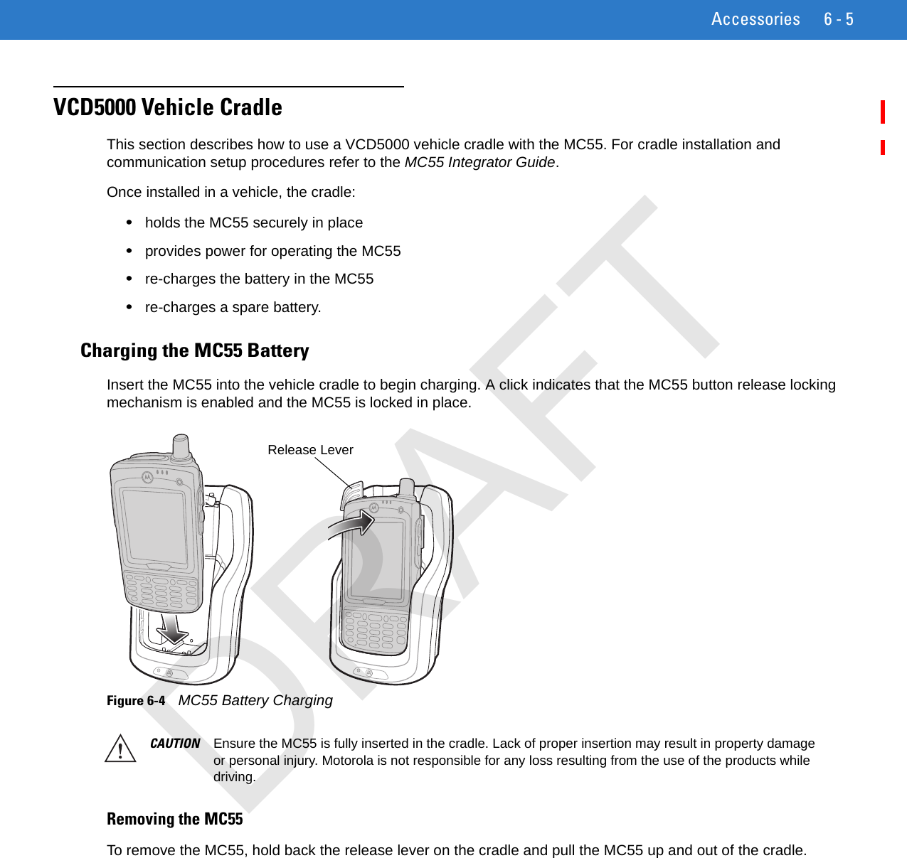
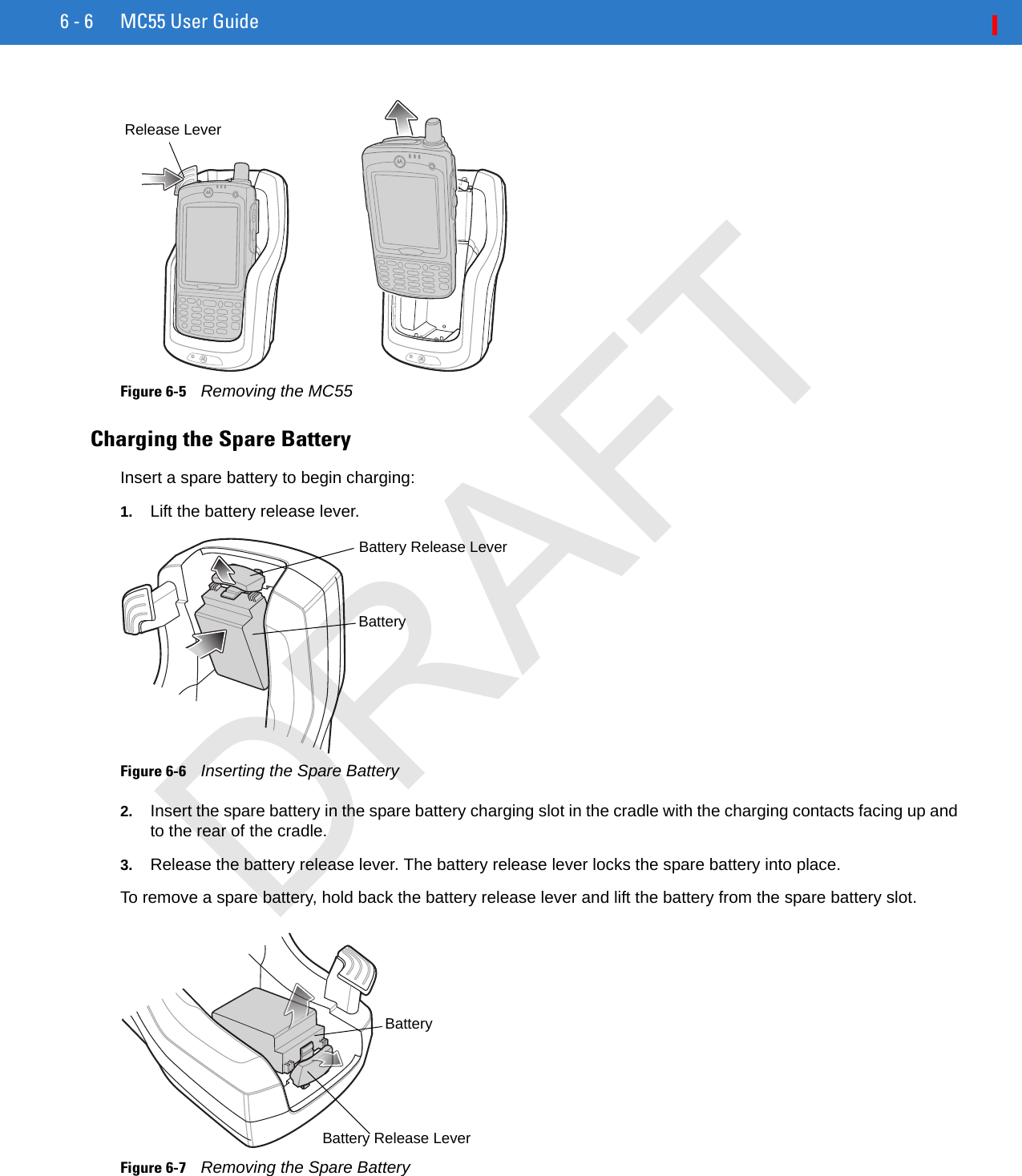
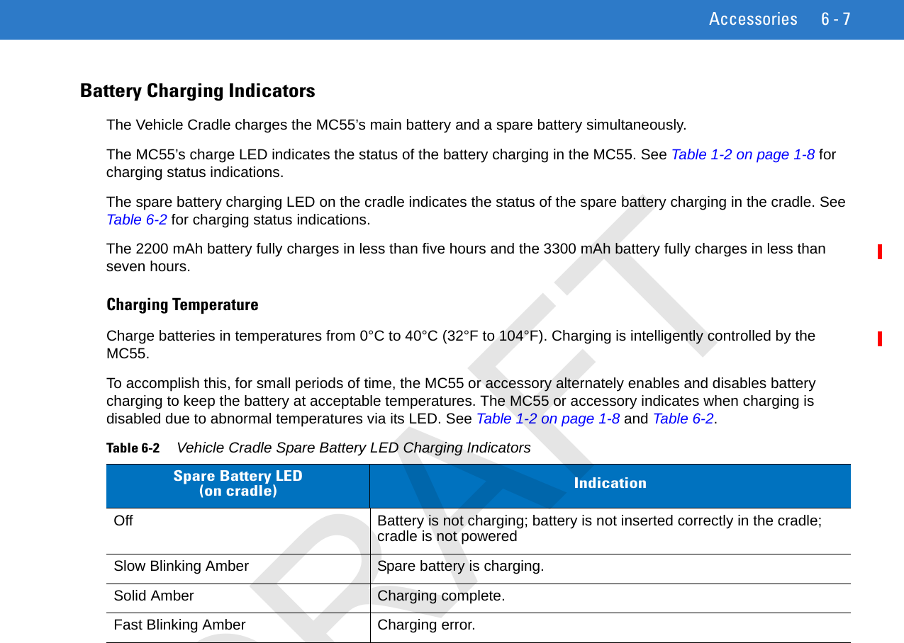
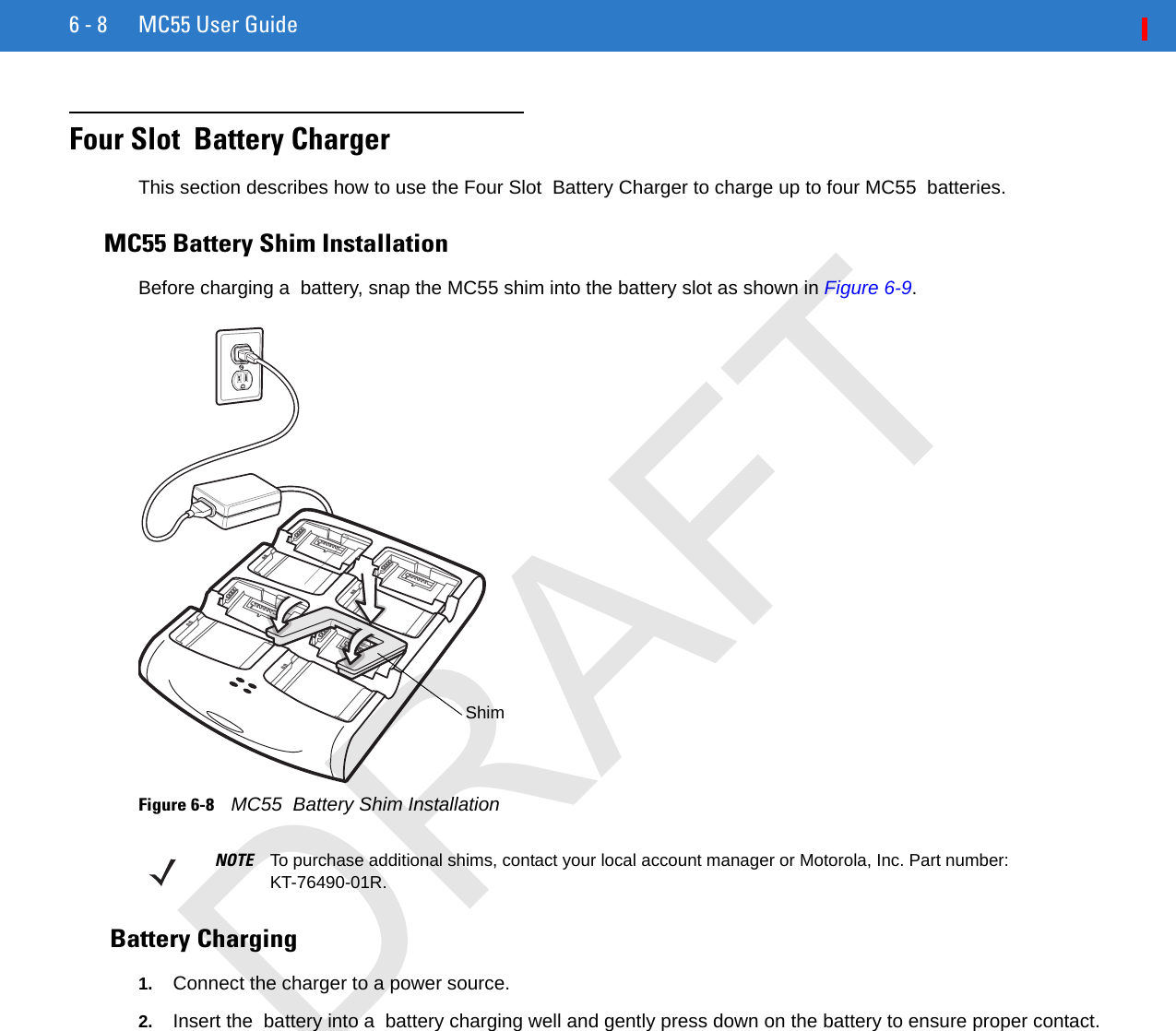
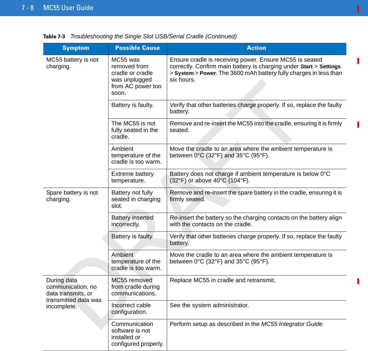
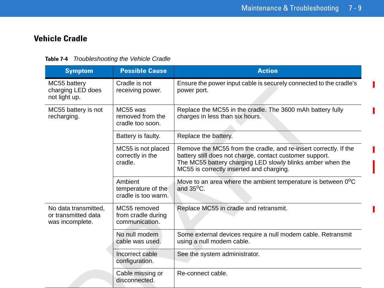
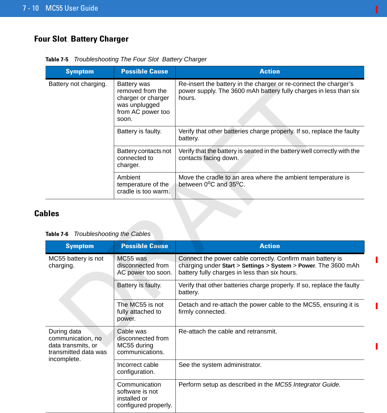
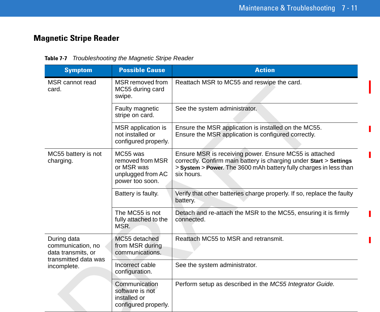
UserMan4 update