Symbol Technologies MC75A6 EDA (Enterprise Digital Assistant) User Manual MC75A User Guide
Symbol Technologies Inc EDA (Enterprise Digital Assistant) MC75A User Guide
Contents
User manual 5

Technical Specifications A - 3
Wireless WAN Data and Voice Communications
Wireless Wide Area Network
(WWAN) radios
MC75A6:
GSM: HSDPA (850, 900, 1800, 1900 and 2100 MHz)
MC75A8:
CDMA: EVDO Rev A (800 and 1900 MHz)
GPS Integrated Assisted-GPS (A-GPS), autonomous GPS
Wireless LAN Data and Voice Communications
Wireless Local Area Network
(WLAN) radio Tri-mode IEEE
®
802.11a/b/g
Data Rates Supported 1, 2, 5.5, 6, 9, 11, 12, 18, 24, 36, 48, and 54 Mbps
Operating Channels Chan 8-169 (5040 – 5845 MHz)
Chan 1-13 (2412-2472 MHz) Chan 14 (2484 MHz) Japan only
Actual operating frequencies depend on regulatory rules and certification
agency
Security WPA2, WPA, WEP (40 or 128 bit), TKIP, TLS, TTLS (MS-CHAP), TTLS
(MS-CHAP v2), TTLS (CHAP), TTLS-MD5, TTLS-PAP, PEAP-TLS, PEAP
(MS-CHAP v2), AES, LEAP
Spreading Technique Direct Sequence Spread Spectrum (DSSS) and Orthogonal Frequency Division
Multiplexing (OFDM)
Antenna Internal for WLAN and Bluetooth
Voice Communication Integrated Voice-over-IP ready (P2P, PBX, PTT), Wi-Fi™-certified, IEEE
802.11a/b/g direct sequence wireless LAN
Wireless PAN Data and Voice Communications
Bluetooth Class II, v 2.1 with EDR; on-board chip antenna.
Data Capture Specifications
Options 2D imager, 1D linear, color camera
Linear 1D Scanner (SE950) Specifications
Optical Resolution 0.005 in. minimum element width
Roll +/- 30° from vertical
Pitch Angle +/- 65° from normal
Skew Tolerance +/- 60° from normal
Ambient Light Sunlight: 8,000 ft. candles (86,112 Lux)
Artificial Light: 450 ft. candles (4,844 Lux)
Shock 2,000 +/- 5% G
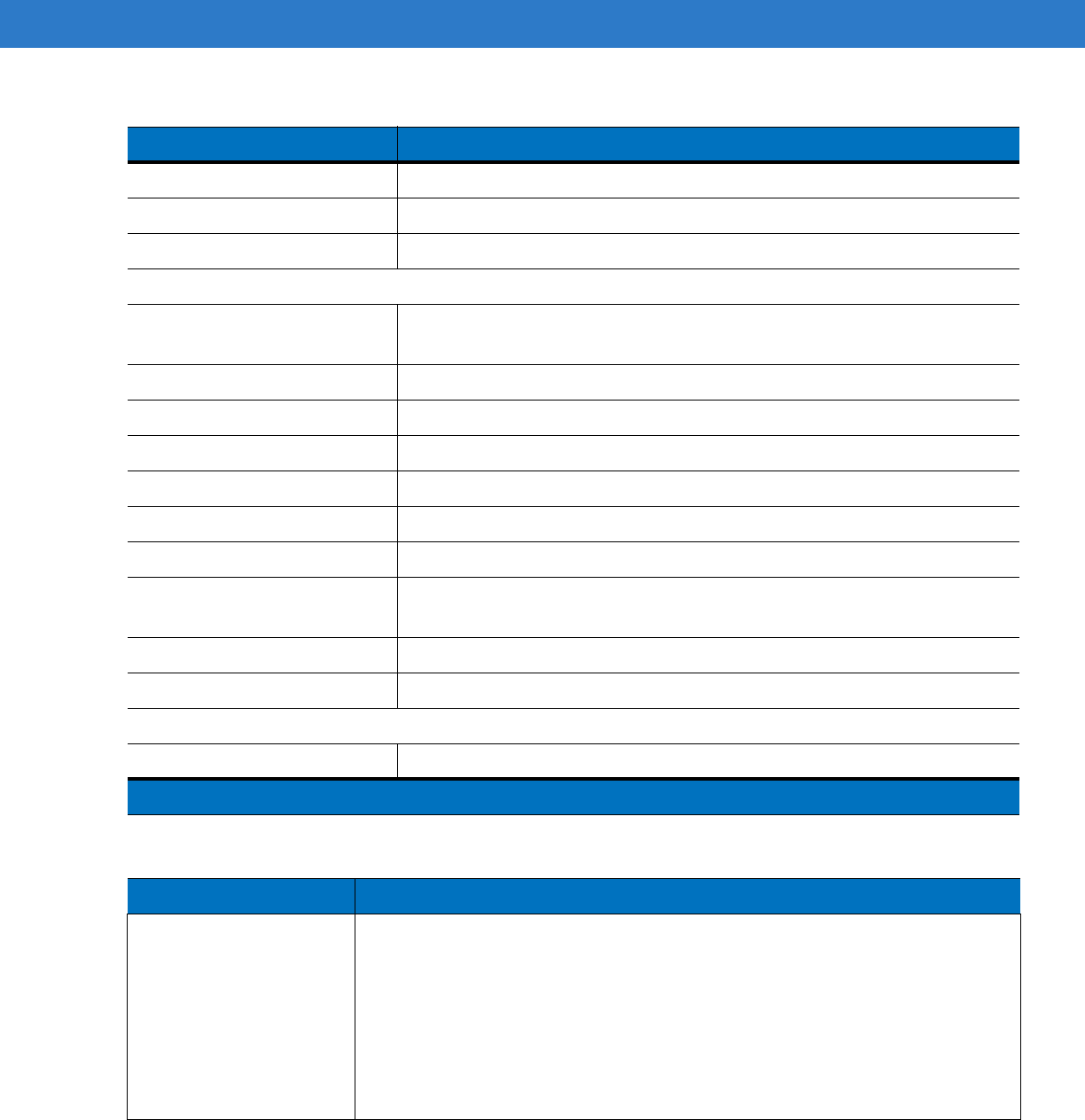
Table A-1
MC75A Technical Specifications (Continued)
Item Description
Note 1: Total output power can be either USB or serial or a combination of both that cannot exceed 200 mA.
DRAFT
A - 4 MC75A Enterprise Digital Assistant User Guide
Scan Rate 50 (+/- 6) scans/sec (bidirectional)
Scan Angle 46.5° (typical)
Laser Power 1.0 mW nominal
2D Imager Engine (SE4500) Specifications
Field of View Horizontal - 40°
Vertical - 25°
Optical Resolution 752X 480 V pixels (gray scale)
Roll 360°
Pitch Angle +/- 60° from normal
Skew Tolerance +/- 60° from normal
Ambient Light 9,000 ft. candles (96,900 Lux)
Shock 2,000 +/- 5% G
Focal Distance from Front of
Engine Near: 5 inches
Far: 9 inches
Aiming Element (VLD) 655 nm +/- 10 nm
Illumination Element (LED) 625 nm +/- 5 nm
Camera Specifications
Resolution 2 Mega pixel with auto focus and flash
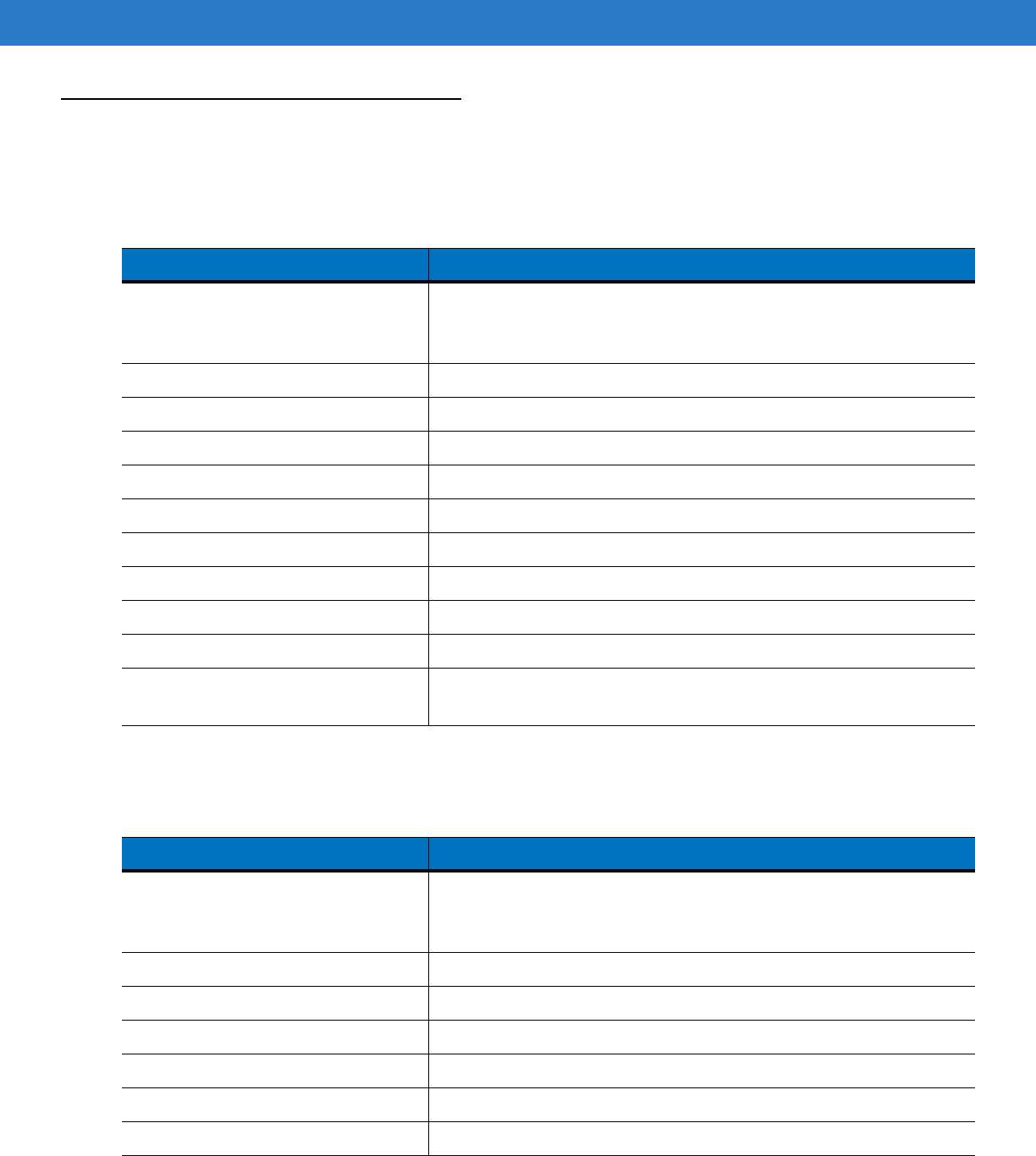
Table A-2
Data Capture Options
Item Description
Laser Decode Capability Code 39 Code 128 Code 93
Codabar Code 11 Discrete 2 of 5
Interleaved 2 of 5 EAN-8 EAN-13
MSI UPCA UPCE
UPC/EAN supplementals Coupon Code Trioptic 39
Webcode Chinese 2 of 5 GS1 DataBar
GS1 DataBar Truncated GS1 DataBar Limited GS1 DataBar Stacked
GS1 DataBar Expanded GS1 DataBar Expanded Stacked
GS1 DataBar Stacked Omni
Table A-1
MC75A Technical Specifications (Continued)
Item Description
Note 1: Total output power can be either USB or serial or a combination of both that cannot exceed 200 mA.
DRAFT

Technical Specifications A - 5
Imaging Decode Capability Code 39 Code 128 Code 93
Codabar Code 11 Interleaved 2 of 5
Discrete 2 of 5 MSI EAN-8
EAN-13 UPCA UPCE
UPC/EAN supplementals Coupon Code Trioptic 39
Webcode TLC39 Composite AB
Composite C Micro PDF-417 PDF-417
Macro PDF-417 (Macro) Micro PDF-417 QR Code
Data Matrix Maxi Code US Postnet*
US Planet UK 4-state Australian 4-state
Canadian 4-state Japanese 4-state Dutch Kix
Chinese 2 of 5 USPS 4-state (US4CB) Aztec
microQR GS1 DataBar GS1 DataBar Truncated
GS1 DataBar Limited GS1 DataBar Stacked GS1 DataBar Expanded
GS1 DataBar Expanded Stacked GS1 DataBar Stacked Omni
Camera Decode Capability Code 39 Code 128 Code 93
Codabar Code 11 Interleaved 2 of 5
Discrete 2 of 5 MSI EAN-8
EAN-13 UPCA UPCE
UPC/EAN supplementals Coupon Code Trioptic 39
Webcode TLC39 Composite AB
Composite C Micro PDF-417 PDF-417
Macro PDF-417 (Macro) Micro PDF-417 QR Code
Data Matrix Maxi Code US Postnet*
US Planet UK 4-state Australian 4-state
Canadian 4-state Japanese 4-state Dutch Kix
GS1 DataBar GS1 DataBar Truncated GS1 DataBar Limited
GS1 DataBar Stacked GS1 DataBar Expanded GS1 DataBar
Expanded Stacked GS1 DataBar Stacked Omni
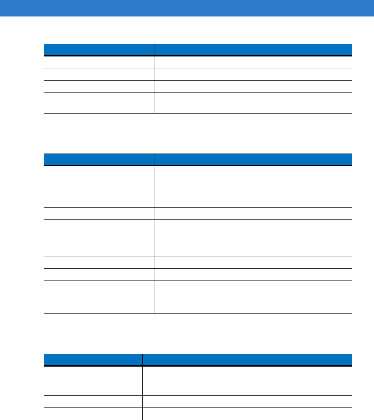
Table A-2
Data Capture Options (Continued)
Item Description
DRAFT
A - 6 MC75A Enterprise Digital Assistant User Guide
MC75A Accessory Specifications
Single Slot USB/Serial Cradle
Four Slot Ethernet Cradle
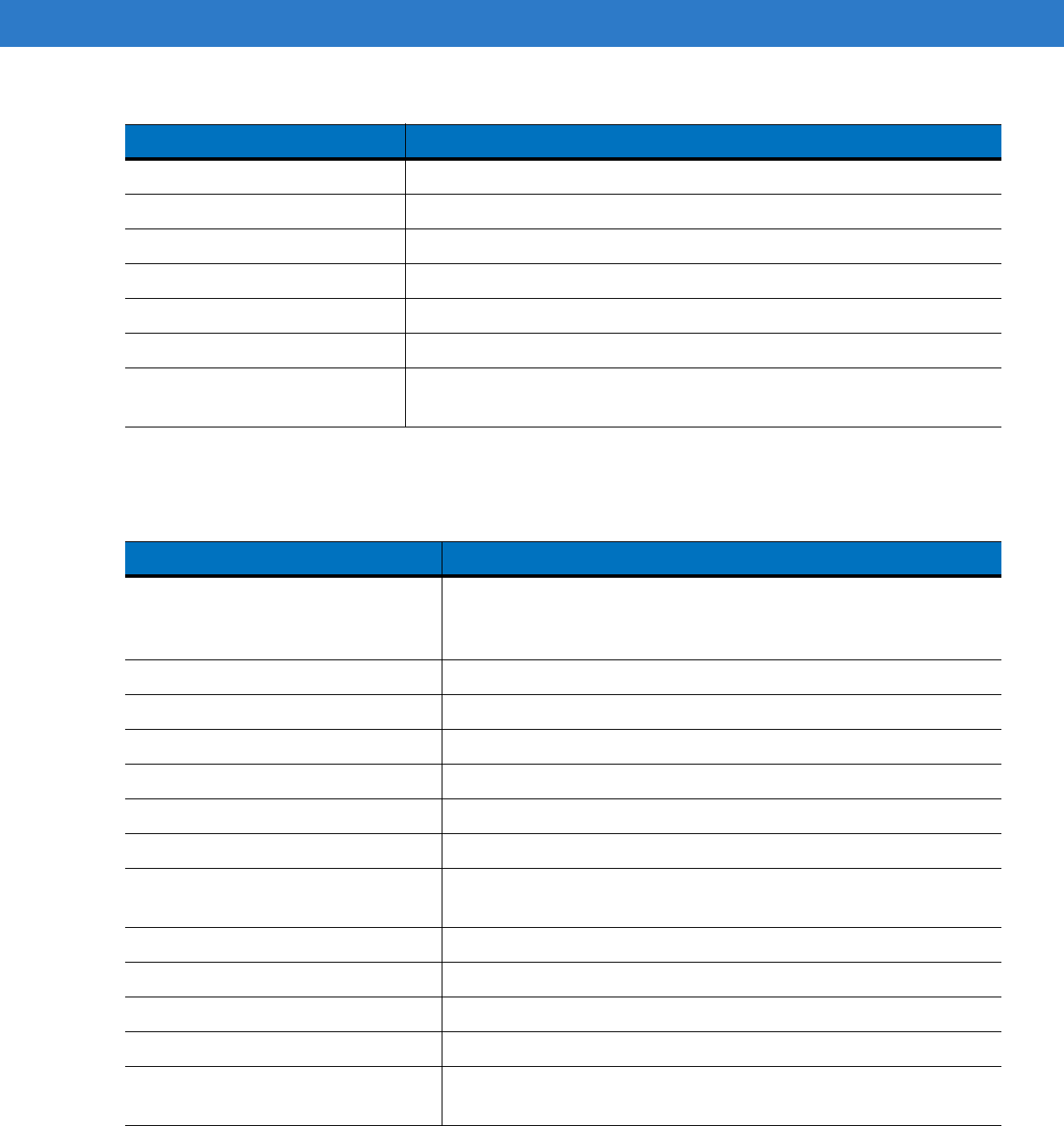
Table A-3
Single Slot USB/Serial Cradle Technical Specifications
Feature Description
Dimensions Length: 14.54 cm (5.72 in.)
Width: 11.05 cm (4.35 in.)
Height: 9.10 cm (3.58 in.)
Weight 196 g (6.9 oz)
Input Power 12 VDC
Power Consumption 30 watts
Interface USB, Serial
Operating Temperature 0°C to 50°C (32°F to 122°F)
Storage Temperature -40°C to 70°C (-40°F to 158°F)
Charging Temperature 0°C to 40°C (32°F to 104°F)
Humidity 5% to 95% non-condensing
Drop 76.2 cm (30.0 in.) drops to vinyl tiled concrete at room temperature
Electrostatic Discharge (ESD) +/- 15 kV air
+/- 8 kV contact
Table A-4
Four Slot Ethernet Cradle Technical Specifications
Feature Description
Dimensions Length: 46.80 cm (18.42 in.)
Width: 10.90 cm (4.29 in.)
Height: 13.70 cm (5.39 in.)
Weight 1079 g (2.38 lb)
Input Power 12 VDC
Power Consumption 100 watts
Interface Ethernet
Operating Temperature 0°C to 50°C (32°F to 122°F)
Storage Temperature -40°C to 70°C (-40°F to 158°F)
DRAFT
Technical Specifications A - 7
Four Slot Charge Only Cradle
Four Slot Battery Charger
Charging Temperature 0°C to 40°C (32°F to 104°F)
Humidity 5% to 95% non-condensing
Drop 76.2 cm (30.0 in.) drops to vinyl tiled concrete at room temperature
Electrostatic Discharge (ESD) +/- 15 kV air
+/- 8 kV contact
Table A-4
Four Slot Ethernet Cradle Technical Specifications (Continued)
Feature Description
Table A-5
Four Slot Charge Only Cradle Technical Specifications
Feature Description
Dimensions Length: 46.80 cm (18.42 in.)
Width: 10.90 cm (4.29 in.)
Height: 13.70 cm (5.39 in.)
Weight 1079 g (2.38 lb)
Input Power 12 VDC
Power Consumption 100 watts
Operating Temperature 0°C to 50°C (32°F to 122°F)
Storage Temperature -40°C to 70°C (-40°F to 158°F)
Charging Temperature 0°C to 40°C (32°F to 104°F)
Humidity 5% to 95% non-condensing
Drop 76.2 cm (30.0 in.) drops to vinyl tiled concrete at room temperature
Electrostatic Discharge (ESD) +/- 15 kV air
+/- 8 kV contact
Table A-6
Four Slot Battery Charger Technical Specifications
Feature Description
Dimensions Length: 21.0 cm (8.27 in.)
Width: 15.50 cm (6.10 in.)
Height: 3.47 cm (1.37 in.)
Weight 386 g (13.6 oz)
Input Power 12 VDC
DRAFT
A - 8 MC75A Enterprise Digital Assistant User Guide
Magnetic Stripe Reader
Power Consumption 30 watts
Operating Temperature 0°C to 50°C (32°F to 122°F)
Storage Temperature -40°C to 70°C (-40°F to 158°F)
Charging Temperature 0°C to 40°C (32°F to 104°F)
Humidity 5% to 95% non-condensing
Drop 76.2 cm (30.0 in.) drops to vinyl tiled concrete at room temperature
Electrostatic Discharge (ESD) +/- 15 kV air
+/- 8 kV contact
Table A-6
Four Slot Battery Charger Technical Specifications (Continued)
Feature Description
Table A-7
Magnetic Stripe Reader (MSR) Technical Specifications
Feature Description
Dimensions Length: 7.87 cm (3.1 in.)
Width: 8.38 cm (3.3 in.)
Height: 3.56 cm (1.4 in.)
Weight 48 g (1.7 oz)
Interface Serial with baud rate up to 19,200
Format ANSI, ISO, AAMVA, CA DMV, user-configurable generic format
Swipe Speed 5 to 50 in. (127 to 1270 mm) /sec, bi-directional
Decoders Generic, Raw Data
Mode Buffered, unbuffered
Track Reading Capabilities Tracks 1 and 3: 210 bpi
Track 2: 75 and 210 bpi, autodetect
Operating Temperature 0°C to 50°C (32°F to 122°F)
Storage Temperature -40°C to 70°C (-40°F to 158°F)
Humidity 5% to 95% non-condensing
Drop 1.22 m (4 ft.) drops to concrete
Electrostatic Discharge (ESD) +/- 15 kV air
+/- 8 kV contact
DRAFT
Appendix B Keypads
Introduction
The MC75A offers five types of keypad configurations: Numeric, DSD, QWERTY, AZERTY and QWERTZ.
Numeric Keypad Configuration
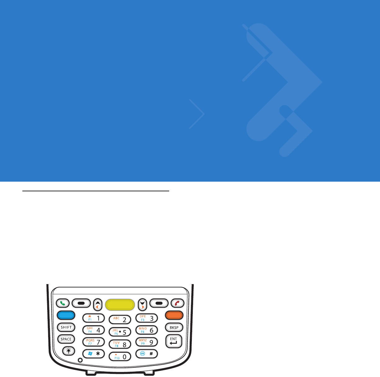
The numeric keypad contains application keys, scroll keys, and function keys. The keypad is color-coded to
indicate the alternate function key (blue) values. Note that an application can change keypad functions so the
MC75A’s keypad may not function exactly as described. See Table B-1 for key and button descriptions and Table
B-2 on page B-4 for the keypad’s special functions.
Figure B-1
MC75A Numeric Keypad
F2
DRAFT
B - 2 MC75A Enterprise Digital Assistant User Guide
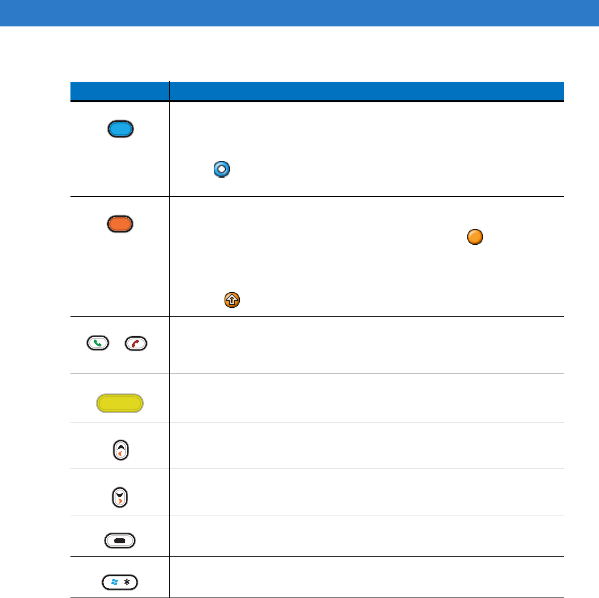
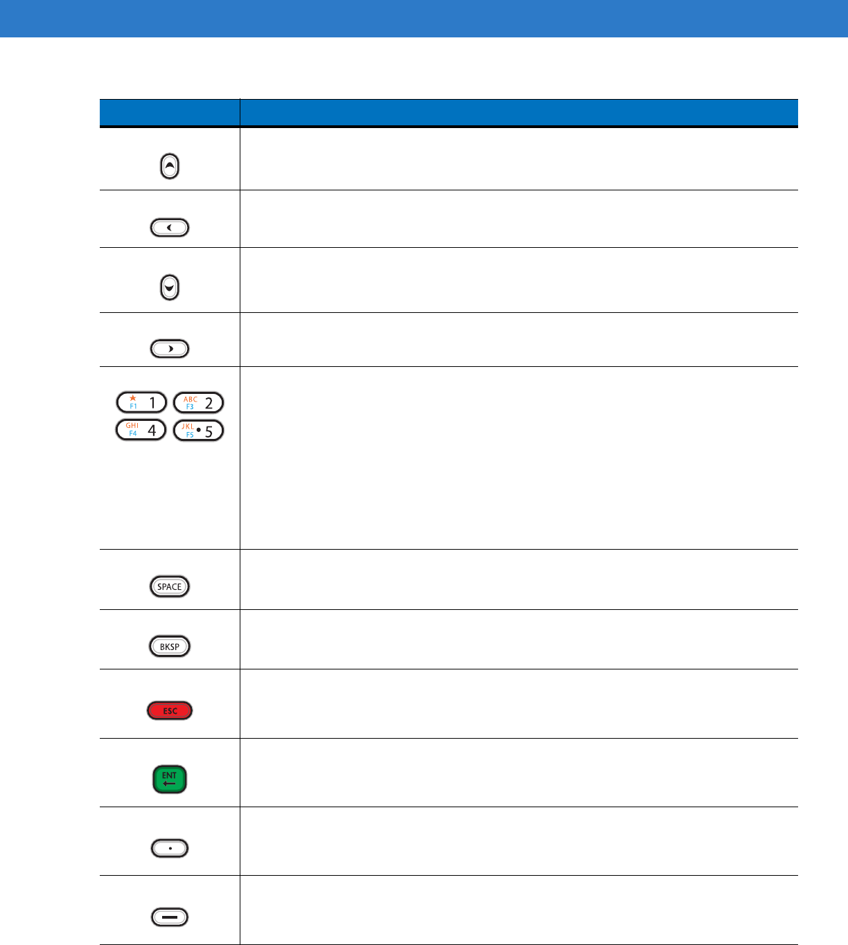
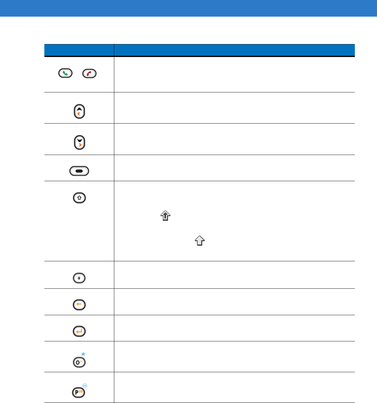
Table B-1
MC75A Numeric Keypad Descriptions
Key Description
Blue Key (left)
Use this key to launch applications or access items (shown on the keypad in blue).
Press the Blue key once to activate this mode, followed by another key.
A single press displays the following icon at the bottom of the screen, until a second key is
pressed:
Orange Key
Use this key to access the secondary layer of characters and actions (shown on the keypad
in orange). Press the Orange key once to lock the keypad into Alpha state.
A single press displays the following icon at the bottom of the screen:
Press the Orange key a second time to return to the normal state.
Press the Orange key, then the Shift key to add a temporary shift (that applies only to the
next key pressed) to the orange lock state. This displays the following icon at the bottom of
the screen:
Talk/End
Talk (Green Phone): press to display the phone keypad window or to dial a phone number
(from the phone keypad window).
End (Red Phone): press when the phone keypad window displays to stop dialing or end a
call.
Scan (yellow)
Activates the scanner/imager in a scan enabled application.
Scroll Up and Down
Moves up one item.
Moves left one item when pressed with the Orange key.
Scroll Left and Right
Moves down one item.
Moves right one item when pressed with the Orange key.
Soft Keys
Accesses the command or menu above it on the screen.
Star
Produces an asterisk in default state.
Press and release the blue key, then press the Star key to open the Start menu.
DRAFT
Keypads B - 3
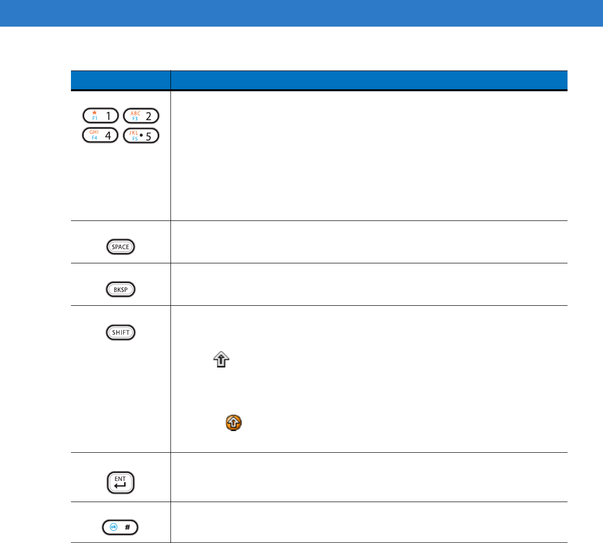
Alphanumeric
In default state, produces the numeric value on the key.
In Alpha state, produces the lower case alphabetic characters on the key. Each key press
produces the next alphabetic character in sequence. For example, press and release the
Orange key and then press the ‘4’ key once to produce the letter ‘g’; press and release the
Orange key and then press the ‘4’ key three times to produce the letter ‘i’.
Press the SHIFT key in Alpha state to produce the upper case alphabetic characters on the
key. For example, press and release the Orange key, press and release the SHIFT key, and
then press the ‘4’ key once to produce the letter ‘G’; press and release the Orange key,
press and release the SHIFT key and then press the ‘4’ key three times to produce the letter
‘I’.
SPACE
Produces a space.
BACKSPACE
Produces a backspace.
SHIFT
Press and release the SHIFT key to activate the keypad alternate SHIFT functions.
A single press displays the following icon at the bottom of the screen, until a second key is
pressed:
Press the Orange key, then the Shift key to add a temporary shift (that applies only to the
next key pressed) to the orange lock state. This displays the following icon at the bottom of
the screen:
ENT (Enter)
Executes a selected item or function.
Pound
Produces a pound/number sign.
Press and release the blue key, then press the Pound key to produce an OK.
Table B-1
MC75A Numeric Keypad Descriptions (Continued)
Key Description
DRAFT

B - 4 MC75A Enterprise Digital Assistant User Guide
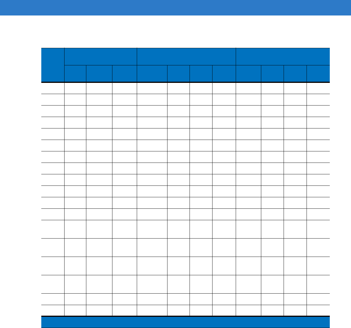
Table B-2
Numeric Keypad Input Modes
Key
Numeric Mode Orange Key
(Alpha Lowercase Mode)
Orange + Shift Keys
(Alpha Uppercase Mode)
Blue+
Key
SHIFT
+ Key
1st
Press
2nd
Press
3rd
Press
4th
Press
1st
Press
2nd
Press
3rd
Press
4th
Press
11F1! * *** * ***
22F2@a bc A BC
33F3# d ef D EF
44F4$ g hi G HI
55F5%j kl J KL
66F6^ m no MNO
77F7& p qr sP QRS
88F8* t uv T UV
99F9( w xyzWXYZ
00F10) . >
Up Up Up Hilight
Up Left Left
Down Down Down Hilight
Down Right Right
Enter Action Action Action Action Action
Note: An application can change the key functions. The keypad may not function exactly as described.
DRAFT
Keypads B - 5
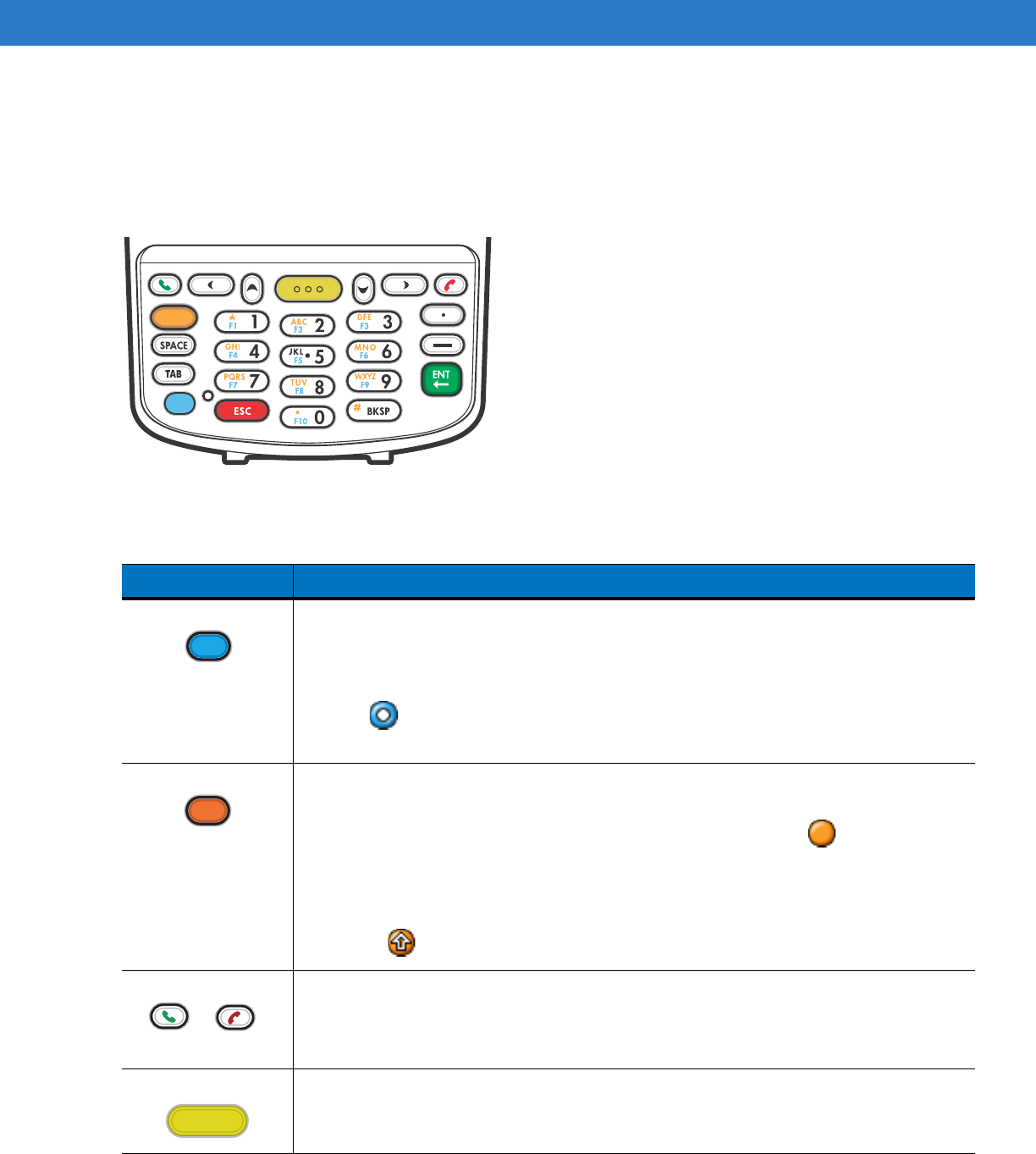
DSD Keypad Configuration
The DSD keypad contains application keys, scroll keys, and function keys. The keypad is color-coded to indicate
the alternate function key (blue) values. Note that an application can change keypad functions so the MC75A’s
keypad may not function exactly as described. See Table B-3 for key and button descriptions and Table B-4 on
page B-7 for the keypad’s special functions.
Figure B-2
MC75A DSD Keypad
Table B-3
MC75A DSD Keypad Descriptions
Key Description
Blue Key (left)
Use this key to launch applications or access items (shown on the keypad in blue).
Press the Blue key once to activate this mode, followed by another key.
A single press displays the following icon at the bottom of the screen, until a second key is
pressed:
Orange Key
Use this key to access the secondary layer of characters and actions (shown on the keypad
in orange). Press the Orange key once to lock the keypad into Alpha state.
A single press displays the following icon at the bottom of the screen:
Press the Orange key a second time to return to the normal state.
Press the Orange key, then the Shift key to add a temporary shift (that applies only to the
next key pressed) to the orange lock state. This displays the following icon at the bottom of
the screen:
Talk/End
Talk (Green Phone): press to display the phone keypad window or to dial a phone number
(from the phone keypad window).
End (Red Phone): press when the phone keypad window displays to stop dialing or end a
call.
Scan (yellow)
Activates the scanner/imager in a scan enabled application.
DRAFT
B - 6 MC75A Enterprise Digital Assistant User Guide
Scroll Up
Moves up one item.
Scroll Left
Moves left one item.
Scroll Down
Moves down one item.
Scroll Right
Moves right one item.
Alphanumeric
In default state, produces the numeric value on the key.
In Alpha state, produces the lower case alphabetic characters on the key. Each key press
produces the next alphabetic character in sequence. For example, press and release the
Orange key and then press the ‘4’ key once to produce the letter ‘g’; press and release the
Orange key and then press the ‘4’ key three times to produce the letter ‘i’.
Press the SHIFT key in Alpha state to produce the upper case alphabetic characters on the
key. For example, press and release the Orange key, press and release the SHIFT key, and
then press the ‘4’ key once to produce the letter ‘G’; press and release the Orange key,
press and release the SHIFT key and then press the ‘4’ key three times to produce the letter
‘I’.
SPACE
Produces a space.
BACKSPACE
Produces a backspace.
ESC
Cancels an operation or action.
ENT (Enter)
Executes a selected item or function.
Period
Produces a period character.
Dash
Produces a dash character.
Table B-3
MC75A DSD Keypad Descriptions (Continued)
Key Description
DRAFT
Keypads B - 7
Table B-4
DSD Keypad Input Modes
Key
Numeric Mode Orange Key
(Alpha Lowercase Mode)
Orange + Shift Keys
(Alpha Uppercase Mode)
Blue+
Key
SHIFT
+ Key
1st
Press
2nd
Press
3rd
Press
4th
Press
1st
Press
2nd
Press
3rd
Press
4th
Press
11F1! * *** * ***
22F2@a bc A BC
33F3# d ef D EF
44F4$ g hi G HI
55F5%j kl J KL
66F6^ m no MNO
77F7& p qr sP QRS
88F8* t uv T UV
99F9( w xyzWXYZ
00F10) . >
... .
--- -
Up Up Up Hilight
Up
Down Down Down Hilight
Down
Left Left Left Hilight
Left
Right Right Right Hilight
Right
Enter Action Action Action Action Action
ESC ESC ESC ESC ESC ESC
Note: An application can change the key functions. The keypad may not function exactly as described.
DRAFT
B - 8 MC75A Enterprise Digital Assistant User Guide
Alpha-numeric Keypad Configurations
The three types of alpha-numeric keypads produce the 26-character alphabet (A-Z, both lowercase and
uppercase), numbers (0-9), and assorted characters. The keypad is color-coded to indicate which modifier key to
press to produce a particular character or action. The keypad default is alphabetic, producing lowercase letters.
See Table B-5 for key and button descriptions and Table B-6 on page B-11 for the keypad’s special functions.
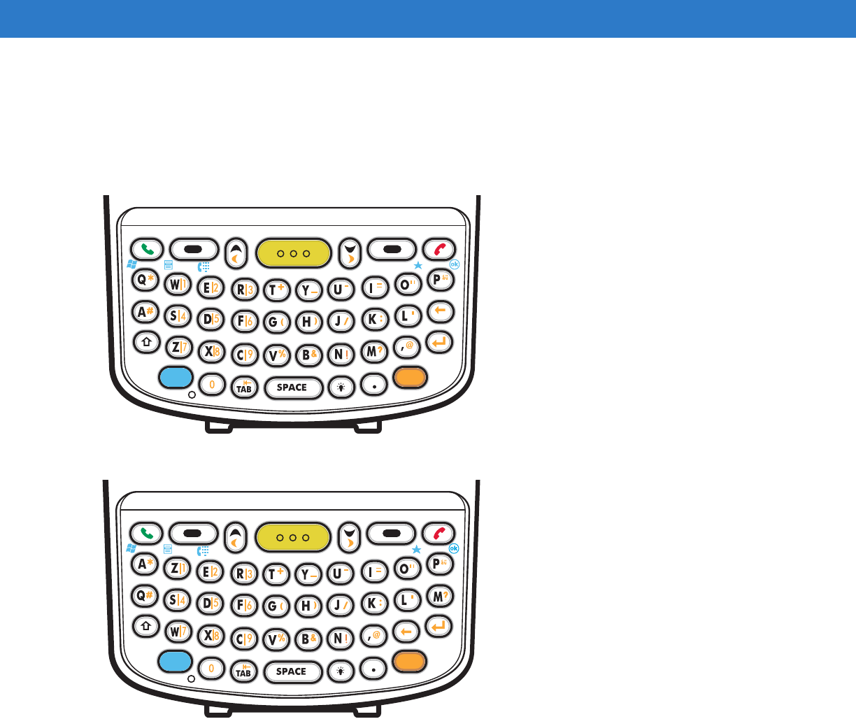
Figure B-3
QWERTY Keypad Configuration
Figure B-4
AZERTY Keypad Configuration
DRAFT
Keypads B - 9
Figure B-5
QWERTZ Keypad Configuration
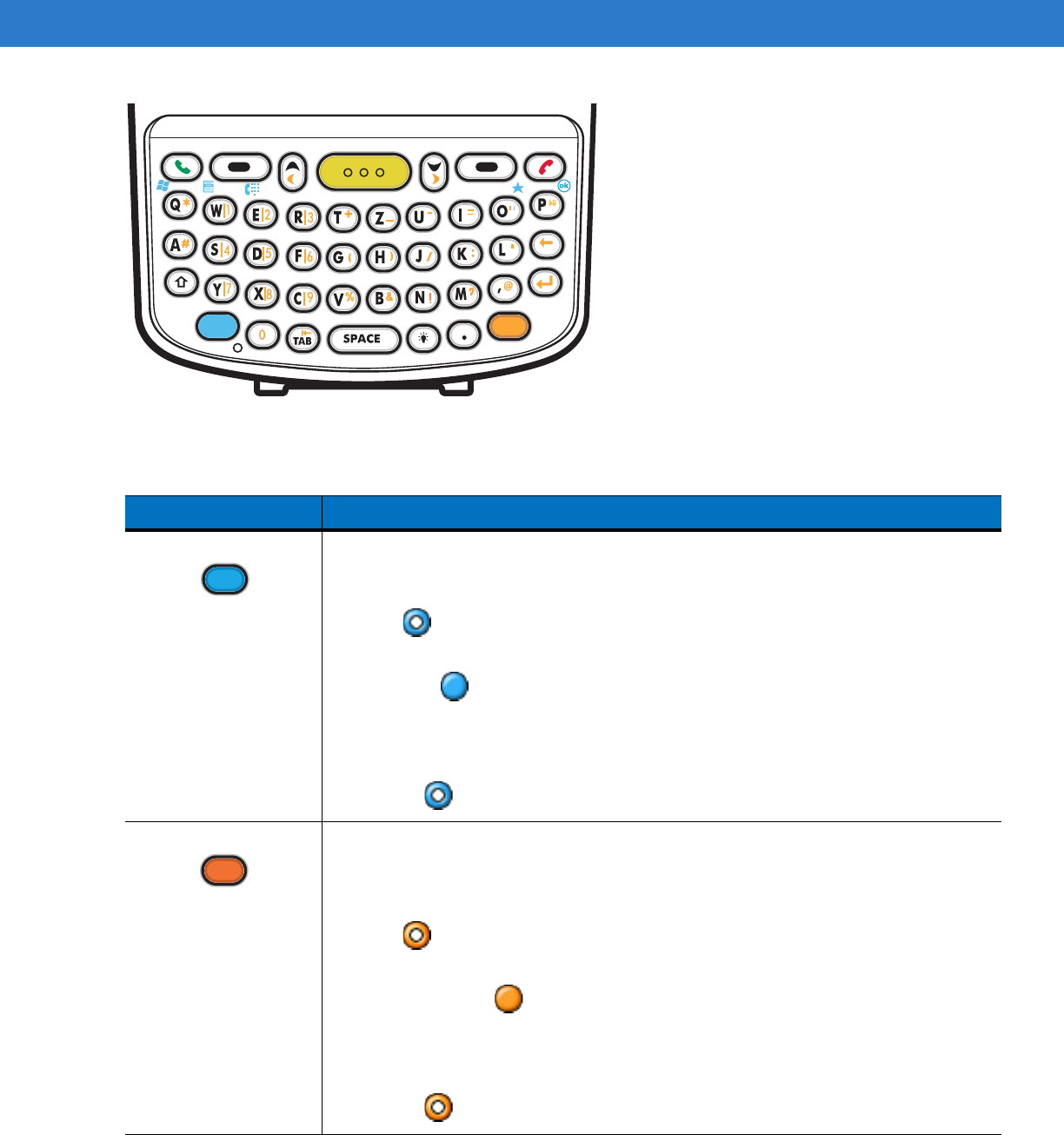
Table B-5
Alpha-numeric Keypad Descriptions
Key Action
Blue Key Launches applications (shown on the keypad in blue).
Press the Blue key once to activate this mode temporarily, followed by another key. This
displays the following icon at the bottom of the screen, until a second key is
pressed:
Press the Blue key twice to lock this mode. This displays the following icon at the bottom
of the screen:
Press the Blue key a third time to unlock.
Press and hold the Blue key while selecting a sequence of keys to activate this mode
temporarily. This displays the following icon at the bottom of the screen as long as the key
is pressed:
Orange Key Accesses the secondary layer of characters and actions (shown on the keypad in
orange).
Press the Orange key once to activate this mode temporarily, followed by another key.
This displays the following icon at the bottom of the screen, until a second key is
pressed:
Press the Orange key twice to lock this mode. This displays the following icon at the
bottom of the screen:
Press the Orange key a third time to unlock.
Press and hold the Orange key while selecting a sequence of keys to activate this mode
temporarily. This displays the following icon at the bottom of the screen as long as the key
is pressed:
DRAFT
B - 10 MC75A Enterprise Digital Assistant User Guide
Talk/End Talk (Green Phone): press to display the phone keypad window or to dial a phone number
(from the phone keypad window).
End (Red Phone): press when the phone keypad window displays to stop dialing or end a
call.
Scroll Up and Left Moves up one item.
Moves left one item when pressed with the Orange key.
Scroll Down and Right Moves down one item.
Moves right one item when pressed with the Orange key.
Soft Keys
Accesses the command or menu above it on the screen.
Shift
Changes the state of the alpha characters from lowercase to uppercase.
•
Press the Shift key to activate this mode temporarily, followed by another key.
This displays the following icon at the bottom of the screen, until a second key is
pressed:
•
Press the Shift key twice to lock this mode. This displays the following icon at the
bottom of the screen:
•
Press the Shift key a third time to unlock.
Backlight Turns the display backlight on and off.
Backspace Produces a backspace.
Enter Executes a selected item or function.
Star Use this key in conjunction with the Blue key to produces an asterisk.
OK Use this key in conjunction with the Blue key as an OK or close button. This function is
user programmable.
Table B-5
Alpha-numeric Keypad Descriptions (Continued)
Key Action
DRAFT
Keypads B - 11
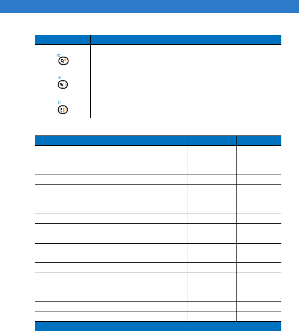
Start Menu Use this key in conjunction with the Blue key to instantly display the Start menu from any
application without tapping the screen. This function is user programmable.
Menu Use this key in conjunction with the Blue key to instantly display the context menu from
any application without tapping the screen. This function is user programmable.
Phonepad
Use this key in conjunction with the Blue key to display the Phonepad application
without tapping the screen. This function is user programmable.
Table B-6
QWERTY Keypad Input Modes
Key Normal Shift + Key Orange + Key Blue + Key
Q q Q * Start Menu
W w W 1 Menu
E e E 2 Phone
Rr R 3
Tt T +
Yy Y _
Uu U -
Ii I =
Oo O “ *
Pp P áü OK
Aa A #
Ss S 4
Dd D 5
Ff F 6
Gg G (
Hh H )
Jj J /
Kk K :
Note: An application can change the key functions. The keypad may not function exactly as described.
Table B-5
Alpha-numeric Keypad Descriptions (Continued)
Key Action
DRAFT

B - 12 MC75A Enterprise Digital Assistant User Guide
Ll L ‘
Backspace Backspace
Shift Shift
Zz Z 7
Xx X 8
Cc C 9
Vv V %
Bb B &
Nn N !
Mm M ?
,, <@
ENTER Enter
00 0 0 0
TAB Tab Tab Back tab Tab
SPACE Space Space Space Space
Backlight Backlight Backlight Backlight Backlight
Star * * * *
.. >. .
Table B-7
AZERTY Keypad Input Modes
Key Normal Shift + Key Orange + Key Blue + Key
A a A * Start Menu
Z z Z 1 Menu
E e E 2 Phone
Rr R 3
Tt T +
Yy Y _
Uu U -
Note: An application can change the key functions. The keypad may not function exactly as described.
Table B-6
QWERTY Keypad Input Modes (Continued)
Key Normal Shift + Key Orange + Key Blue + Key
Note: An application can change the key functions. The keypad may not function exactly as described.
DRAFT

Keypads B - 13
Ii I =
Oo O “ *
Pp P áü OK
Qq Q #
Ss S 4
Dd D 5
Ff F 6
Gg G (
Hh H )
Jj J /
Kk K :
Ll L ‘
Mm M ?
Shift Shift
Ww W 7
Xx X 8
Cc C 9
Vv V %
Bb B &
Nn N !
,, <@
Backspace backspace
Enter Enter
00 0 0 0
TAB Tab Tab Back tab Tab
SPACE Space Space Space Space
Backlight Backlight Backlight Backlight Backlight
.. >. .
Table B-7
AZERTY Keypad Input Modes (Continued)
Key Normal Shift + Key Orange + Key Blue + Key
Note: An application can change the key functions. The keypad may not function exactly as described.
DRAFT

B - 14 MC75A Enterprise Digital Assistant User Guide
Table B-8
QWERTZ Keypad Input Modes
Key Normal Shift + Key Orange + Key Blue + Key
Q q Q * Start Menu
W w W 1 Menu
E e E 2 Phone
Rr R 3
Tt T +
Zz Z _
Uu U -
Ii I =
Oo O “ *
Pp P áü OK
Aa A #
Ss S 4
Dd D 5
Ff F 6
Gg G (
Hh H )
Jj J /
Kk K :
Ll L ‘
Backspace Backspace
Shift Shift
Yy Y 7
Xx X 8
Cc C 9
Vv V %
Bb B &
Nn N !
Mm M ?
Note: An application can change the key functions. The keypad may not function exactly as described.
DRAFT
Keypads B - 15
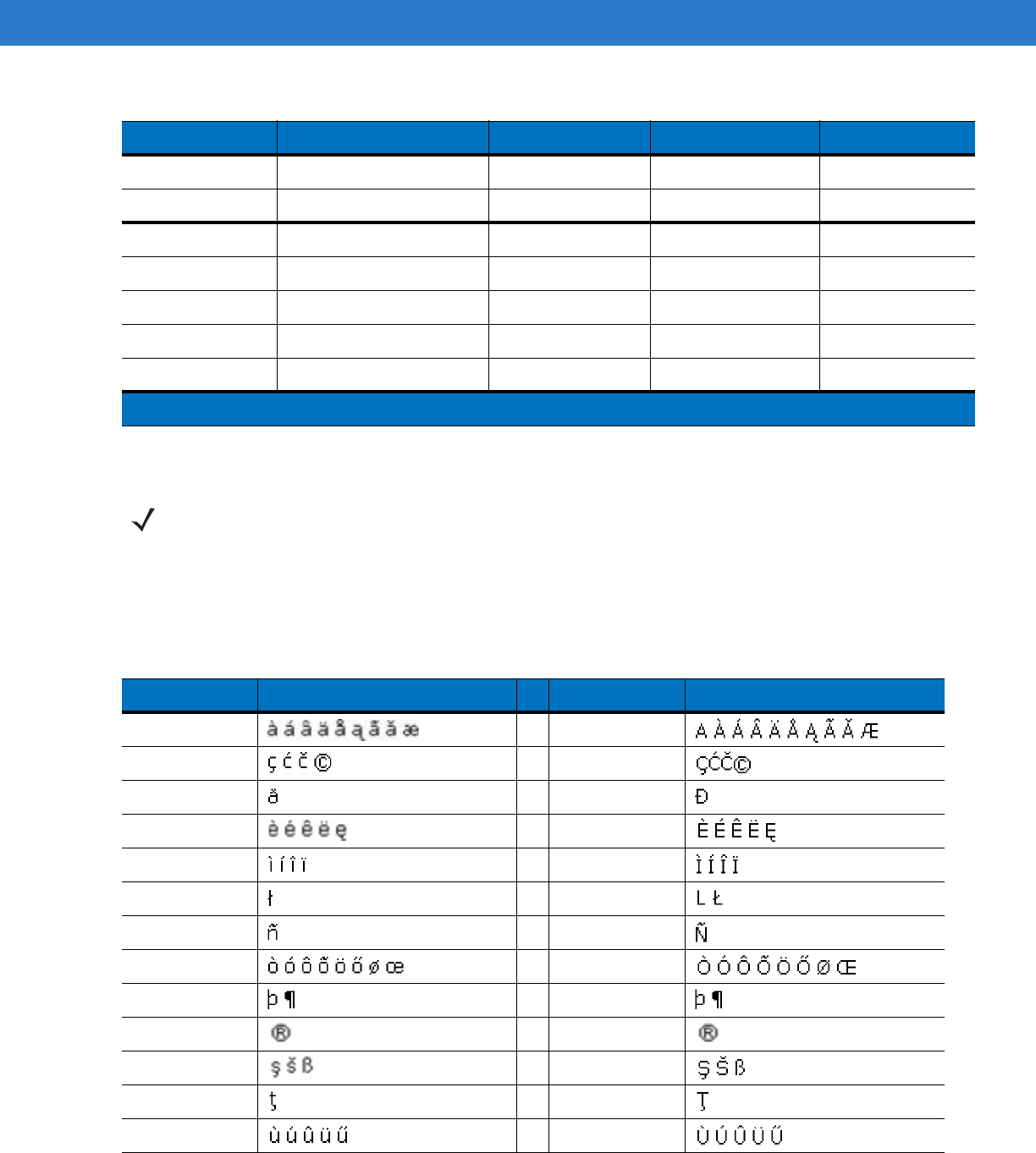
Special Character Key
To add special characters using the MC75A áü key, type the related character first, then press the Orange twice
followed by the áü (P) key. Continue pressing the áü key until the special character displays. To modify an existing
character, move the cursor to the right of the character then press the Orange key twice and then press the áü key
until the special character replaces the original character. Table B-9 lists the special characters you can generate.
,, <@
ENTER Enter
00 0 0 0
TAB Tab Tab Back tab Tab
SPACE Space Space Space Space
Backlight Backlight Backlight Backlight Backlight
.. >. .
Table B-8
QWERTZ Keypad Input Modes (Continued)
Key Normal Shift + Key Orange + Key Blue + Key
Note: An application can change the key functions. The keypad may not function exactly as described.
NOTE Special characters are only available on the alpha-numeric keypad configurations.
Table B-9
Special Characters
Key Special Characters Key Special Characters
aA
cC
dD
eE
iI
lL
nN
oO
pP
rR
sS
tT
uU
DRAFT
B - 16 MC75A Enterprise Digital Assistant User Guide
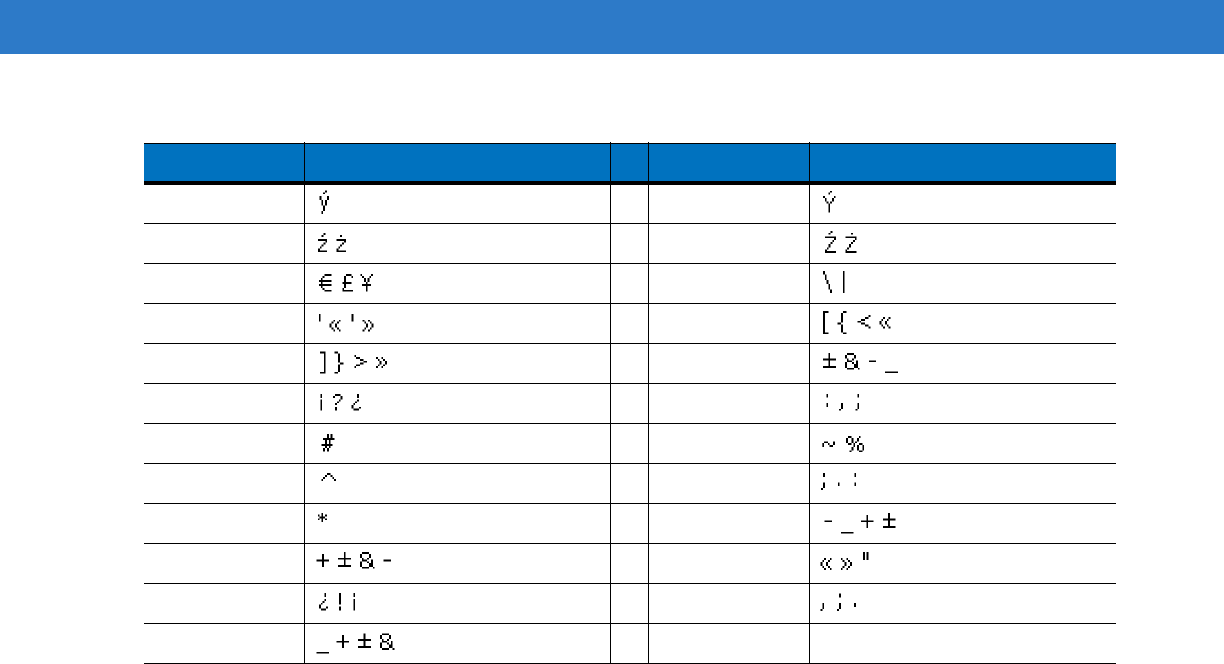
yY
zZ
$/
“(
)+
!.
*@
%,
#&
_‘
?:
-
Table B-9
Special Characters (Continued)
Key Special Characters Key Special Characters
DRAFT

Appendix C Voice Quality Manager
Introduction
The Voice Quality Manager (VQM) is a software package that resides on the MC75A. VQM enables a set of
features for Voice over WiFi (VoWiFi) calls, and a sub-set of those features for cellular line (GSM or CDMA) calls.
The VQM user interface is designed to be intuitive and easy to use, so complex tasks such as enabling the
Acoustic Echo Canceller (AEC) while a call is in progress are done with very little or no user intervention.
Features
The VQM software:
•
Improves the voice transmission quality without using additional battery power.
•
Turns on the AEC for VoWiFi calls automatically, without user intervention.
•
Prioritizes the outgoing audio IP packets.
•
Provides user-selectable audio modes (speakerphone and handset) with a single tap of the VQM icon. A
VQM icon in the title bar of the device indicates the audio mode currently in use.
•
NDIS 5.1 compliant.
Enabling VQM
To enable VQM:
1. Tap Start > Programs > File Explorer.
2. Navigate to the Windows folder.
3. Locate the file VQMAudioNotify.
4. Tap the filename to enable VQM.
DRAFT
C - 2 MC75A Enterprise Digital Assistant User Guide
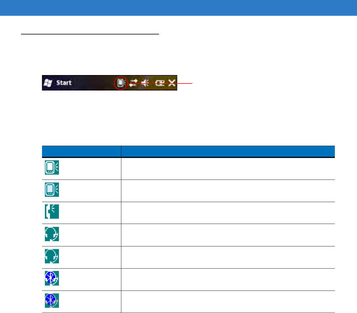
Audio Modes
The MC75A can be in any one of the seven different audio modes. The mode is visually indicated by the VQM icon
on the title bar.
Figure C-1
VQM Icon in Title Bar
The VQM icon indicates that the device is in speakerphone mode without Acoustic Echo Cancellation (indicated by
the gray VQM icon). The audio modes and their corresponding VQM title bar icons are:
Changing Audio Modes
Depending upon the audio mode being used, the mode can be changed by tapping the VQM icon in the title bar.
The audio mode can only be changed while the user is on a call.
Table C-1
VQM Icons
Icon Description
Speakerphone with Acoustic Echo Cancellation.
Speakerphone without Acoustic Echo Cancellation.
Handset with Acoustic Echo Cancellation (device is in handset mode only while on
a call).
Headset while on a call (Acoustic Echo Cancellation is not enabled for wired or
Bluetooth headsets).
Headset while not on a call.
Bluetooth headset while on a call (Acoustic Echo Cancellation is not enabled for
wired or Bluetooth headsets). White icon.
Bluetooth headset while not on a call. Gray icon.
VQM icon
DRAFT
Voice Quality Manager C - 3
The table below lists the current audio mode and the subsequent audio mode after tapping the VQM icon.
If the audio mode is set to speakerphone and the user taps the VQM icon, the audio mode changes to handset.
If the user is using a Bluetooth headset, tapping the VQM icon un-pairs the Bluetooth headset from the device
causing the audio to be routed to the default mode. In VQM 2.5, there is no way to go back to the Bluetooth
headset using the VQM icon if it is un-paired The only way to reconnect the Bluetooth headset to the device is by
using the BTExplorer application.
If the user taps the VQM icon when a wired headset is connected to the mobile device, the audio mode does not
change. The audio continues to get routed to the wired headset.
If the user taps the VQM icon while not on a call there is not change to the audio mode.
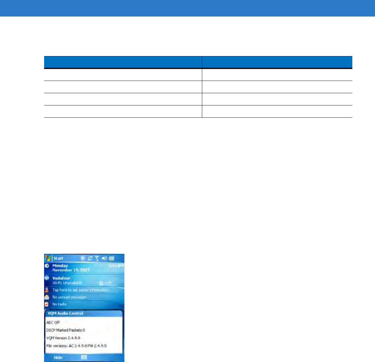
Tap and hold the VQM icon in the title bar to display a notification dialog box that contains:
•
AEC: The Acoustic Echo Canceller status
•
DSCP Marked Packets: The number of outbound voice packets that have been recognized and marked as
high priority by VQM.
•
VQM Version: The VQM version number.
Figure C-2
VQM Audio Control Dialog Box
Table C-2
Changing Audio Modes
Audio Mode before Tapping VQM Icon Audio Mode after Tapping VQM Icon
Speakerphone Handset
Handset Speakerphone
Wired headset Wired headset
Bluetooth headset Speakerphone
DRAFT

C - 4 MC75A Enterprise Digital Assistant User Guide
Voice Packet Prioritization
IP soft phones transmit voice packets in the same manner as any other application that sends data over the
network. On a network with different types of traffic, voice packets are given the same priority as any other traffic,
and therefore may be subject to delays.
WiFi Multi-media (WMM) is a solution to this problem. WMM is a specification that supports prioritizing traffic, and
“higher-priority” packets can be given preferential treatment.
To make use of WMM, the devices that generate traffic must mark their packets as high or normal priority in a field
in the IP packet called Differentiated Services Code-Point (DSCP). The wireless infrastructure, which must be
configured to support WMM, gives a higher priority to packets that have been marked as high priority through
DSCP marking by the devices that generate traffic.
VQM detects if there is an ongoing Voice over WiFi (VoWiFi) call, and if so, marks outgoing voice packets (Only
outgoing voice packets can be marked. The incoming voice packets have already been through the network, so it
makes no sense to mark them.) as high-priority using DSCP. This enables WMM-compatible wireless infrastructure
to treat the voice packets preferentially. This results in fewer delays for voice packets, which in turn improves the
call quality.
Acoustic Echo Cancellation
Acoustic Echo occurs during a voice call when the audio from the earpiece enters the microphone of the same
device. This results in the person at the other end hearing back a delayed version of his/her own voice (“Echo”).
Needless to say, “Echo” is not desirable, and needs to be suppressed. This is the functionality performed by the
Acoustic Echo Canceller (AEC). There are two approaches to suppressing the Echo:
•
Turn the Acoustic Echo Canceller (AEC) on permanently. This approach is not very efficient because the
device consumes more power when the AEC is on.
•
Turn the Acoustic Echo Canceller (AEC) on only when there is an ongoing call.
VQM follows the second of the two approaches mentioned above.
VQM automatically turns on the Acoustic Echo Canceller (AEC) when the mobile device is in a VoWiFi call. When
the call is terminated, VQM turns the AEC off. Note that the AEC is turned on for speakerphone and handset
modes and does not get turned on for wired headset and Bluetooth headset modes. The AEC is not required for
wired headset because the audio volume is quite low (because of the proximity of the earpiece to the ear), and
therefore it is very unlikely for the audio from the earpiece to go in to the mouthpiece. Bluetooth headsets typically
have an Echo Canceller built in. Turning the AEC on only while on a call saves battery power, compared to leaving
the AEC turned on permanently.
The AEC is not turned on for Cellular calls because the WWAN phone application has a built-in echo canceller.
Limitations
•
There is no VPN support in VQM.
•
Only the Avaya softphone is supported.
Disabling VQM
To disable VQM perform a warm boot.
DRAFT

Glossary
A
API. An interface by means of which one software component communicates with or controls another. Usually used to refer
to services provided by one software component to another, usually via software interrupts or function calls
Aperture. The opening in an optical system defined by a lens or baffle that establishes the field of view.
Application Programming Interface. See API.
ANSI Terminal. A display terminal that follows commands in the ANSI standard terminal language. For example, it uses
escape sequences to control the cursor, clear the screen and set colors. Communications programs support the ANSI
terminal mode and often default to this terminal emulation for dial-up connections to online services.
ASCII. American Standard Code for Information Interchange. A 7 bit-plus-parity code representing 128 letters, numerals,
punctuation marks and control characters. It is a standard data transmission code in the U.S.
Autodiscrimination. The ability of an interface controller to determine the code type of a scanned bar code. After this
determination is made, the information content is decoded.
B
Bar. The dark element in a printed bar code symbol.
Bar Code. A pattern of variable-width bars and spaces which represents numeric or alphanumeric data in machine-readable
form. The general format of a bar code symbol consists of a leading margin, start character, data or message character,
check character (if any), stop character, and trailing margin. Within this framework, each recognizable symbology uses
its own unique format. See Symbology.
Bar Code Density. The number of characters represented per unit of measurement (e.g., characters per inch).
Bar Height. The dimension of a bar measured perpendicular to the bar width.
DRAFT

Glossary - 2 MC75A Enterprise Digital Assistant User Guide
Bar Width. Thickness of a bar measured from the edge closest to the symbol start character to the trailing edge of the same
bar.
BIOS. Basic Input Output System. A collection of ROM-based code with a standard API used to interface with standard PC
hardware.
Bit. Binary digit. One bit is the basic unit of binary information. Generally, eight consecutive bits compose one byte of data.
The pattern of 0 and 1 values within the byte determines its meaning.
Bits per Second (bps). Bits transmitted or received.
BOOTP. A protocol for remote booting of diskless devices. Assigns an IP address to a machine and may specify a boot file.
The client sends a bootp request as a broadcast to the bootp server port (67) and the bootp server responds using the
bootp client port (68). The bootp server must have a table of all devices, associated MAC addresses and IP addresses.
boot or boot-up
The process a computer goes through when it starts. During boot-up, the computer can run self-diagnostic tests and
configure hardware and software.
bps. See Bits Per Second.
Byte. On an addressable boundary, eight adjacent binary digits (0 and 1) combined in a pattern to represent a specific
character or numeric value. Bits are numbered from the right, 0 through 7, with bit 0 the low-order bit. One byte in
memory is used to store one ASCII character.
C
CDMA. Code Division Multiple Access (CDMA) is a form of multiplexing and a method of multiple access that does not
divide up the channel by time (as in TDMA), or frequency (as in FDMA), but instead encodes data with a special code
associated with each channel and uses the constructive interference properties of the special codes to perform the
multiplexing.
CDRH. Center for Devices and Radiological Health. A federal agency responsible for regulating laser product safety. This
agency specifies various laser operation classes based on power output during operation.
CDRH Class 1. This is the lowest power CDRH laser classification. This class is considered intrinsically safe, even if all laser
output were directed into the eye's pupil. There are no special operating procedures for this class.
CDRH Class 2. No additional software mechanisms are needed to conform to this limit. Laser operation in this class poses
no danger for unintentional direct human exposure.
Character. A pattern of bars and spaces which either directly represents data or indicates a control function, such as a
number, letter, punctuation mark, or communications control contained in a message.
Character Set. Those characters available for encoding in a particular bar code symbology.
Check Digit. A digit used to verify a correct symbol decode. The scanner inserts the decoded data into an arithmetic formula
and checks that the resulting number matches the encoded check digit. Check digits are required for UPC but are
optional for other symbologies. Using check digits decreases the chance of substitution errors when a symbol is
decoded.
DRAFT

Glossary - 3
Codabar. A discrete self-checking code with a character set consisting of digits 0 to 9 and six additional characters: (“-”, “$”,
“:”, “/”, “,” and “+”).
Code 128. A high density symbology which allows the controller to encode all 128 ASCII characters without adding extra
symbol elements.
Code 3 of 9 (Code 39). A versatile and widely used alphanumeric bar code symbology with a set of 43 character types,
including all uppercase letters, numerals from 0 to 9 and 7 special characters (“-”, “.”, “/”, “+”, “%”, “$” and space). The
code name is derived from the fact that 3 of 9 elements representing a character are wide, while the remaining 6 are
narrow.
Code 93. An industrial symbology compatible with Code 39 but offering a full character ASCII set and a higher coding
density than Code 39.
Code Length. Number of data characters in a bar code between the start and stop characters, not including those
characters.
Cold Boot. A cold boot restarts the mobile computer and erases all user stored records and entries.
COM port. Communication port; ports are identified by number, e.g., COM1, COM2.
Continuous Code. A bar code or symbol in which all spaces within the symbol are parts of characters. There are no
intercharacter gaps in a continuous code. The absence of gaps allows for greater information density.
Cradle. A cradle is used for charging the terminal battery and for communicating with a host computer, and provides a
storage place for the terminal when not in use.
D
Data Communications Equipment (DCE). A device (such as a modem) which is designed to attach directly to a DTE (Data
Terminal Equipment) device.
DCE. See Data Communications Equipment.
DCP. See Device Configuration Package.
Dead Zone. An area within a scanner's field of view, in which specular reflection may prevent a successful decode.
Decode. To recognize a bar code symbology (e.g., UPC/EAN) and then analyze the content of the specific bar code
scanned.
Decode Algorithm. A decoding scheme that converts pulse widths into data representation of the letters or numbers
encoded within a bar code symbol.
Decryption. Decryption is the decoding and unscrambling of received encrypted data. Also see, Encryption and Key.
Depth of Field. The range between minimum and maximum distances at which a scanner can read a symbol with a certain
minimum element width.
DRAFT

Glossary - 4 MC75A Enterprise Digital Assistant User Guide
Device Configuration Package. The Symbol Device Configuration Package provides the Product Reference Guide (PRG),
flash partitions, Terminal Configuration Manager (TCM) and the associated TCM scripts. With this package hex images
that represent flash partitions can be created and downloaded to the mobile computer.
Discrete Code. A bar code or symbol in which the spaces between characters (intercharacter gaps) are not part of the code.
Discrete 2 of 5. A binary bar code symbology representing each character by a group of five bars, two of which are wide.
The location of wide bars in the group determines which character is encoded; spaces are insignificant. Only numeric
characters (0 to 9) and START/STOP characters may be encoded.
DRAM. Dynamic random access memory.
DTE. See Data Terminal Equipment.
E
EAN. European Article Number. This European/International version of the UPC provides its own coding format and
symbology standards. Element dimensions are specified metrically. EAN is used primarily in retail.
Element. Generic term for a bar or space.
Encoded Area. Total linear dimension occupied by all characters of a code pattern, including start/stop characters and data.
ENQ (RS-232). ENQ software handshaking is also supported for the data sent to the host.
ESD. Electro-Static Discharge
EvDO, 1xEV-DO. A wireless radio broadband data standard adopted by many CDMA mobile phone service providers. It is
standardized by 3GPP2, as part of the CDMA2000 family of standards.
F
File Transfer Protocol (FTP). A TCP/IP application protocol governing file transfer via network or telephone lines. See
TCP/IP.
Flash Disk. An additional megabyte of non-volatile memory for storing application and configuration files.
Flash Memory. Flash memory is nonvolatile, semi-permanent storage that can be electronically erased in the circuit and
reprogrammed. Series 9000 mobile computers use Flash memory to store the operating system (ROM-DOS), the
terminal emulators, and the Citrix ICA Client for DOS.
FTP. See File Transfer Protocol.
H
Hard Reset. See Cold Boot.
DRAFT

Glossary - 5
Hz. Hertz; A unit of frequency equal to one cycle per second.
Host Computer. A computer that serves other terminals in a network, providing such services as computation, database
access, supervisory programs and network control.
High-Speed Downlink Packet Access (HSDPA). A 3G (third generation) mobile telephony communications protocol in the
High-Speed Packet Access (HSPA) family, which allows networks based on Universal Mobile Telecommunications
System (UMTS) to have higher data transfer speeds and capacity.
I
IDE. Intelligent drive electronics. Refers to the solid-state hard drive type.
IEC. International Electrotechnical Commission. This international agency regulates laser safety by specifying various laser
operation classes based on power output during operation.
IEC (825) Class 1. This is the lowest power IEC laser classification. Conformity is ensured through a software restriction of
120 seconds of laser operation within any 1000 second window and an automatic laser shutdown if the scanner's
oscillating mirror fails.
IEEE Address. See MAC Address.
Input/Output Ports. I/O ports are primarily dedicated to passing information into or out of the terminal’s memory. Series
9000 mobile computers include Serial and USB ports.
Interleaved 2 of 5. A binary bar code symbology representing character pairs in groups of five bars and five interleaved
spaces. Interleaving provides for greater information density. The location of wide elements (bar/spaces) within each
group determines which characters are encoded. This continuous code type uses no intercharacter spaces. Only
numeric (0 to 9) and START/STOP characters may be encoded.
Intercharacter Gap. The space between two adjacent bar code characters in a discrete code.
Interleaved Bar Code. A bar code in which characters are paired together, using bars to represent the first character and
the intervening spaces to represent the second.
Internet Protocol Address. See IP.
IOCTL. Input/Output Control.
I/O Ports. interface The connection between two devices, defined by common physical characteristics, signal
characteristics, and signal meanings. Types of interfaces include RS-232 and PCMCIA.
IP. Internet Protocol. The IP part of the TCP/IP communications protocol. IP implements the network layer (layer 3) of the
protocol, which contains a network address and is used to route a message to a different network or subnetwork. IP
accepts “packets” from the layer 4 transport protocol (TCP or UDP), adds its own header to it and delivers a “datagram”
to the layer 2 data link protocol. It may also break the packet into fragments to support the maximum transmission unit
(MTU) of the network.
IP Address. (Internet Protocol address) The address of a computer attached to an IP network. Every client and server
station must have a unique IP address. A 32-bit address used by a computer on a IP network. Client workstations have
DRAFT

Glossary - 6 MC75A Enterprise Digital Assistant User Guide
either a permanent address or one that is dynamically assigned to them each session. IP addresses are written as four
sets of numbers separated by periods; for example, 204.171.64.2.
IPX/SPX. Internet Package Exchange/Sequential Packet Exchange. A communications protocol for Novell. IPX is Novell’s
Layer 3 protocol, similar to XNS and IP, and used in NetWare networks. SPX is Novell's version of the Xerox SPP
protocol.
IS-95. Interim Standard 95. The EIA/TIA standard that governs the operation of CDMA cellular service. Versions include
IS-95A and IS-95B. See CDMA.
K
Key. A key is the specific code used by the algorithm to encrypt or decrypt the data. Also see, Encryption and Decrypting.
L
LASER. Light Amplification by Stimulated Emission of Radiation.The laser is an intense light source. Light from a laser is
all the same frequency, unlike the output of an incandescent bulb. Laser light is typically coherent and has a high energy
density.
Laser Diode. A gallium-arsenide semiconductor type of laser connected to a power source to generate a laser beam. This
laser type is a compact source of coherent light.
laser scanner. A type of bar code reader that uses a beam of laser light.
LCD. See Liquid Crystal Display.
LED Indicator. A semiconductor diode (LED - Light Emitting Diode) used as an indicator, often in digital displays. The
semiconductor uses applied voltage to produce light of a certain frequency determined by the semiconductor's particular
chemical composition.
Light Emitting Diode. See LED.
Liquid Crystal Display (LCD). A display that uses liquid crystal sealed between two glass plates. The crystals are excited
by precise electrical charges, causing them to reflect light outside according to their bias. They use little electricity and
react relatively quickly. They require external light to reflect their information to the user.
M
MC. Mobile Computer.
MDN. Mobile Directory Number. The directory listing telephone number that is dialed (generally using POTS) to reach a
mobile unit. The MDN is usually associated with a MIN in a cellular telephone -- in the US and Canada, the MDN and
MIN are the same value for voice cellular users. International roaming considerations often result in the MDN being
different from the MIN.
DRAFT

Glossary - 7
MIL. 1 mil = 1 thousandth of an inch.
MIN. Mobile Identification Number. The unique account number associated with a cellular device. It is broadcast by the
cellular device when accessing the cellular system.
Misread (Misdecode). A condition which occurs when the data output of a reader or interface controller does not agree with
the data encoded within a bar code symbol.
Mobile Computer. In this text, mobile computer refers to the MC75A. It can be set up to run as a stand-alone device, or it
can be set up to communicate with a network, using wireless radio technology.
N
Nominal. The exact (or ideal) intended value for a specified parameter. Tolerances are specified as positive and negative
deviations from this value.
Nominal Size. Standard size for a bar code symbol. Most UPC/EAN codes are used over a range of magnifications (e.g.,
from 0.80 to 2.00 of nominal).
NVM. Non-Volatile Memory.
O
ODI. See Open Data-Link Interface.
Open Data-Link Interface (ODI). Novell’s driver specification for an interface between network hardware and higher-level
protocols. It supports multiple protocols on a single NIC (Network Interface Controller). It is capable of understanding
and translating any network information or request sent by any other ODI-compatible protocol into something a NetWare
client can understand and process.
Open System Authentication. Open System authentication is a null authentication algorithm.
P
PAN . Personal area network. Using Bluetooth wireless technology, PANs enable devices to communicate wirelessly.
Generally, a wireless PAN consists of a dynamic group of less than 255 devices that communicate within about a 33-foot
range. Only devices within this limited area typically participate in the network.
Parameter
A variable that can have different values assigned to it.
PC Card. A plug-in expansion card for laptop computers and other devices, also called a PCMCIA card. PC Cards are
85.6mm long x 54 mm wide, and have a 68 pin connector. There are several different kinds:
Type I; 3.3 mm high; use - RAM or Flash RAM
DRAFT

Glossary - 8 MC75A Enterprise Digital Assistant User Guide
Type II; 5 mm high; use - modems, LAN adaptors
Type III; 10.5 high; use - Hard Disks
PCMCIA. Personal Computer Memory Card Interface Association. See PC Card.
Percent Decode. The average probability that a single scan of a bar code would result in a successful decode. In a
well-designed bar code scanning system, that probability should approach near 100%.
PING. (Packet Internet Groper) An Internet utility used to determine whether a particular IP address is online. It is used to
test and debug a network by sending out a packet and waiting for a response.
Print Contrast Signal (PCS). Measurement of the contrast (brightness difference) between the bars and spaces of a
symbol. A minimum PCS value is needed for a bar code symbol to be scannable. PCS = (RL - RD) / RL, where RL is
the reflectance factor of the background and RD the reflectance factor of the dark bars.
Programming Mode. The state in which a scanner is configured for parameter values. See Scanning Mode.
Q
Quiet Zone. A clear space, containing no dark marks, which precedes the start character of a bar code symbol and follows
the stop character.
QWERTY. A standard keyboard commonly used on North American and some European PC keyboards. “QWERTY” refers
to the arrangement of keys on the left side of the third row of keys.
R
RAM. Random Access Memory. Data in RAM can be accessed in random order, and quickly written and read.
Reflectance. Amount of light returned from an illuminated surface.
Resolution. The narrowest element dimension which is distinguished by a particular reading device or printed with a
particular device or method.
RF. Radio Frequency.
ROM. Read-Only Memory. Data stored in ROM cannot be changed or removed.
Router. A device that connects networks and supports the required protocols for packet filtering. Routers are typically used
to extend the range of cabling and to organize the topology of a network into subnets. See Subnet.
RS-232. An Electronic Industries Association (EIA) standard that defines the connector, connector pins, and signals used to
transfer data serially from one device to another.
DRAFT

Glossary - 9
S
Scan Area. Area intended to contain a symbol.
Scanner. An electronic device used to scan bar code symbols and produce a digitized pattern that corresponds to the bars
and spaces of the symbol. Its three main components are: 1) Light source (laser or photoelectric cell) - illuminates a bar
code,; 2) Photodetector - registers the difference in reflected light (more light reflected from spaces); 3) Signal
conditioning circuit - transforms optical detector output into a digitized bar pattern.
Scanning Mode. The scanner is energized, programmed and ready to read a bar code.
Scanning Sequence. A method of programming or configuring parameters for a bar code reading system by scanning bar
code menus.
SDK. Software Development Kit
Self-Checking Code. A symbology that uses a checking algorithm to detect encoding errors within the characters of a bar
code symbol.
Shared Key. Shared Key authentication is an algorithm where both the AP and the MU share an authentication key.
SHIP. Symbol Host Interface Program.
SID. System Identification code. An identifier issued by the FCC for each market. It is also broadcast by the cellular carriers
to allow cellular devices to distinguish between the home and roaming service.
SMDK. Symbol Mobility Developer’s Kit.
Soft Reset. See Warm Boot.
Space. The lighter element of a bar code formed by the background between bars.
Specular Reflection. The mirror-like direct reflection of light from a surface, which can cause difficulty decoding a bar code.
Start/Stop Character. A pattern of bars and spaces that provides the scanner with start and stop reading instructions and
scanning direction. The start and stop characters are normally to the left and right margins of a horizontal code.
STEP. Symbol Terminal Enabler Program.
Subnet. A subset of nodes on a network that are serviced by the same router. See Router.
Subnet Mask. A 32-bit number used to separate the network and host sections of an IP address. A custom subnet mask
subdivides an IP network into smaller subsections. The mask is a binary pattern that is matched up with the IP address
to turn part of the host ID address field into a field for subnets. Default is often 255.255.255.0.
Substrate. A foundation material on which a substance or image is placed.
SVTP. Symbol Virtual Terminal Program.
Symbol. A scannable unit that encodes data within the conventions of a certain symbology, usually including start/stop
characters, quiet zones, data characters and check characters.
Symbol Aspect Ratio. The ratio of symbol height to symbol width.
DRAFT

Glossary - 10 MC75A Enterprise Digital Assistant User Guide
Symbol Height. The distance between the outside edges of the quiet zones of the first row and the last row.
Symbol Length. Length of symbol measured from the beginning of the quiet zone (margin) adjacent to the start character
to the end of the quiet zone (margin) adjacent to a stop character.
Symbology. The structural rules and conventions for representing data within a particular bar code type (e.g. UPC/EAN,
Code 39, PDF417, etc.).
T
TCP/IP. (Transmission Control Protocol/Internet Protocol) A communications protocol used to internetwork dissimilar
systems. This standard is the protocol of the Internet and has become the global standard for communications. TCP
provides transport functions, which ensures that the total amount of bytes sent is received correctly at the other end.
UDP is an alternate transport that does not guarantee delivery. It is widely used for real-time voice and video
transmissions where erroneous packets are not retransmitted. IP provides the routing mechanism. TCP/IP is a routable
protocol, which means that all messages contain not only the address of the destination station, but the address of a
destination network. This allows TCP/IP messages to be sent to multiple networks within an organization or around the
world, hence its use in the worldwide Internet. Every client and server in a TCP/IP network requires an IP address, which
is either permanently assigned or dynamically assigned at startup.
Telnet. A terminal emulation protocol commonly used on the Internet and TCP/IP-based networks. It allows a user at a
terminal or computer to log onto a remote device and run a program.
Terminal. See Mobile Computer.
Terminal Emulation. A “terminal emulation” emulates a character-based mainframe session on a remote non-mainframe
terminal, including all display features, commands and function keys. The VC5000 Series supports Terminal Emulations
in 3270, 5250 and VT220.
Terminate and Stay Resident (TSR). A program under DOS that ends its foreground execution to remain resident in
memory to service hardware/software interrupts, providing background operation. It remains in memory and may
provide services on behalf of other DOS programs.
TFTP. (Trivial File Transfer Protocol) A version of the TCP/IP FTP (File Transfer Protocol) protocol that has no directory or
password capability. It is the protocol used for upgrading firmware, downloading software and remote booting of diskless
devices.
Tolerance. Allowable deviation from the nominal bar or space width.
Transmission Control Protocol/Internet Protocol. See TCP/IP.
Trivial File Transfer Protocol. See TFTP.
TSR. See Terminate and Stay Resident.
DRAFT

Glossary - 11
U
UDP. User Datagram Protocol. A protocol within the IP protocol suite that is used in place of TCP when a reliable delivery
is not required. For example, UDP is used for real-time audio and video traffic where lost packets are simply ignored,
because there is no time to retransmit. If UDP is used and a reliable delivery is required, packet sequence checking and
error notification must be written into the applications.
UPC. Universal Product Code. A relatively complex numeric symbology. Each character consists of two bars and two
spaces, each of which is any of four widths. The standard symbology for retail food packages in the United States.
V
Visible Laser Diode (VLD). A solid state device which produces visible laser light.
W
Warm Boot. A warm boot restarts the mobile computer by closing all running programs. All data that is not saved to flash
memory is lost.
DRAFT

Glossary - 12 MC75A Enterprise Digital Assistant User Guide
DRAFT

Index
Numerics
1-D bar codes . . . . . . . . . . . . . . . . . . . . . . . . . . . . . . 3-1
2-D bar codes . . . . . . . . . . . . . . . . . . . . . . . . . . . . . . 3-2
A
accessories
auto charge cable . . . . . . . . . . . . . . . . . . . . . . . . 7-1
cables . . . . . . . . . . . . . . . . . . . . . . . . . . . . .7-2, 7-27
charge cable . . . . . . . . . . . . . . . . . . . . . . . . . . . . 7-1
communication/charge cables
battery charging . . . . . . . . . . . . . . . . . . . . . 7-27
LED indicators . . . . . . . . . . . . . . . . . . . . . . 7-28
DEX cable . . . . . . . . . . . . . . . . . . . . . . . . . . .7-1, 7-2
EMDK . . . . . . . . . . . . . . . . . . . . . . . . . . . . . . . . . 7-2
four slot battery charger . . . . . . . . . . . . . . .7-1, 7-12
four slot charge only cradle . . . . . . . . . . . . . . . . . 7-7
four slot Ethernet cradle . . . . . . . . . . . . 7-1, 7-2, 7-5
headset . . . . . . . . . . . . . . . . . . . . . . . . . . . .7-2, 7-26
holster . . . . . . . . . . . . . . . . . . . . . . . . . . . . . . . . . 7-2
magnetic stripe reader . . . . . . . . . . . 7-2, 7-14, 7-26
microSD card . . . . . . . . . . . . . . . . . . . . . . . . . . . 1-8
modem cable . . . . . . . . . . . . . . . . . . . . . . . . . . . 7-2
modem dongle . . . . . . . . . . . . . . . . . . . . . . . . . . 7-2
modem inverter cable . . . . . . . . . . . . . . . . . . . . . 7-2
MSR . . . . . . . . . . . . . . . . . . . . . . . . . . . . . .7-2, 7-14
installation . . . . . . . . . . . . . . . . . . . . . . . . . . 7-14
magnetic stripe reading . . . . . . . . . . . . . . . 7-14
O’Neil printer cable . . . . . . . . . . . . . . . . . . . . . . . 7-2
serial charge cable . . . . . . . . . . . . . . . . . . . . . . . 7-1
SIM card . . . . . . . . . . . . . . . . . . . . . . . . . . . . . . . 1-3
single slot USB cradle . . . . . . . . . . . . . . . . . . . . . 7-1
single slot USB serial cradle . . . . . . . . . . . . . . . . 7-2
spare battery . . . . . . . . . . . . . . . . . . . . . . . . . . . . 7-2
specifications . . . . . . . . . . . . . . . . . . . . . . . . . . . A-6
stylus . . . . . . . . . . . . . . . . . . . . . . . . . . . . . . . . . . 7-2
USB charge cable . . . . . . . . . . . . . . . . . . . . . . . . 7-1
USB charger cable . . . . . . . . . . . . . . . . . . . . . . . 7-2
vehicle cradle . . . . . . . . . . . . . . . . . . . . . . . . 7-1, 7-9
wall mounting kit, cradle . . . . . . . . . . . . . . . . . . . 7-2
Zebra printer cable . . . . . . . . . . . . . . . . . . . . . . . 7-2
zebra printer cable . . . . . . . . . . . . . . . . . . . . . . . 7-2
Acoustic Echo Cancellation . . . . . . . . . . . . . . . . . . . . C-2
action button . . . . . . . . . . . . . . . . . . . . . . . . . . . . . . 2-21
ActiveSync . . . . . . . . . . . . . . . . . . . . . . . . . . . . . . . . 2-8
icon . . . . . . . . . . . . . . . . . . . . . . . . . . . . . . . . . . . 2-6
adaptive frequency hopping . . . . . . . . . . . . . . . . . . . 6-1
adjusting handstrap . . . . . . . . . . . . . . . . . . . . . . . . . . 1-9
adjusting volume . . . . . . . . . . . . . . . . . . . . . . . . . . . 2-12
AFH . . . . . . . . . . . . . . . . . . . . . . . . . . . . . . . . . . . . . . 6-1
AirBEAM . . . . . . . . . . . . . . . . . . . . . . . . . . . . . . . . . . 2-8
alpha-numeric keypad . . . . . . . . . . . . . . . . . . . . . . . . B-8
key descriptions . . . . . . . . . . . . . . . . . . . . . . . . . B-9
answering a call . . . . . . . . . . . . . . . . . . . . . . . . . . . . 4-7
assisted GPS . . . . . . . . . . . . . . . . . . . . . . . . . . . . . . 5-2
auto charge cable . . . . . . . . . . . . . . . . . . . . . . . 7-1, 7-27
AZERTY . . . . . . . . . . . . . . . . . . . . . . . . . . . . . . . . . . B-8
B
backup battery
charging . . . . . . . . . . . . . . . . . . . . . . . . . . . . . . . 1-5
bar codes
one dimensional . . . . . . . . . . . . . . . . . . . . . . . . . 3-1
two dimensional . . . . . . . . . . . . . . . . . . . . . . . . . 3-2
battery
charging . . . . . . . . . . . . 1-5, 7-3, 7-5, 7-7, 7-9, 7-12
check status . . . . . . . . . . . . . . . . . . . . . . . . . . . . 1-8
installing . . . . . . . . . . . . . . . . . . . . . . . . . . . . . . . 1-4
removing . . . . . . . . . . . . . . . . . . . . . . . . . . . . . . . 1-9
battery charger
charging . . . . . . . . . . . . . . . . . . . . . . . . . . . . . . 7-12
charging indicators . . . . . . . . . . . . . . . . . . . . . . 7-13
DRAFT

Index - 2 MC75A Enterprise Digital Assistant User Guide
battery chargers
communication/charge cables . . . . . . . . . . . . . 7-27
LED indicators . . . . . . . . . . . . . . . . . . . . . . 7-28
four slot . . . . . . . . . . . . . . . . . . . . . . . . . . . . . . . 7-12
battery charging . . . . . . . . . . . . . . . . . . . . . . . . . . . . . 1-5
communication/charge cables . . . . . . . . . . . . . 7-27
using four slot battery charger . . . . . . . . . . . . . 7-12
using four slot Ethernet cradle . . . . . . . . . . .7-5, 7-7
using single slot USB serial cradle . . . . . . . . . . . 7-3
using vehicle cradle . . . . . . . . . . . . . . . . . . . . . . 7-9
battery icon . . . . . . . . . . . . . . . . . . . . . . . . . . . .2-3, 2-13
battery reserve options . . . . . . . . . . . . . . . . . . . . . . 2-13
blue key . . . . . . . . . . . . . . . . . . . . . . . . . . . B-2, B-5, B-9
Bluetooth . . . . . . . . . . . . . . . . . . . . . . . . . . . . . . . . . . 6-1
adaptive frequency hopping . . . . . . . . . . . . . . . . 6-1
bonding . . . . . . . . . . . . . . . . . . . . . . . . . . . . . . . 6-32
deleting bonded device . . . . . . . . . . . . . . . . . . . 6-33
icon . . . . . . . . . . . . . . . . . . . . . . . . . . . . . . . . . . . 2-6
security . . . . . . . . . . . . . . . . . . . . . . . . . . . . . . . . 6-2
turning off . . . . . . . . . . . . . . . . . . . . . . . . . .6-5, 6-16
turning on . . . . . . . . . . . . . . . . . . . . . . . . . .6-4, 6-16
bluetooth
discovering devices . . . . . . . . . . . . . . . . . . .6-5, 6-17
icon . . . . . . . . . . . . . . . . . . . . . . . . . . . . . . . . . . . 2-6
turning on and off . . . . . . . . . . . . . . . . . . . .6-4, 6-16
Bluetooth headset . . . . . . . . . . . . . . . . . . . . . . . . . . . 4-4
bonding
Bluetooth . . . . . . . . . . . . . . . . . . . . . . . . . . . . . . 6-32
bootcold . . . . . . . . . . . . . . . . . . . . . . . . . . . . . . .2-17, 6-3
warm . . . . . . . . . . . . . . . . . . . . . . . . . . . . . .2-17, 6-4
BTExplorer . . . . . . . . . . . . . . . . . . . . . . . . . . . . . . . . . 2-9
bullets . . . . . . . . . . . . . . . . . . . . . . . . . . . . . . . . . . . . xvii
buttons
action . . . . . . . . . . . . . . . . . . . . . . . . . . . . . . . . 2-21
function . . . . . . . . . . . . . . . . . . . . . . . . . . . . . . . 2-20
power . . . . . . . . . . . . . . . . . . . . . . . . 1-7, 2-17, 2-21
scan . . . . . . . . . . . . . . . . . . . . . . . . . . . . . . . . . 2-21
up and down . . . . . . . . . . . . . . . . . . . . . . . . . . . 2-21
C
cables . . . . . . . . . . . . . . . . . . . . . . . . . . . . . . . .7-2, 7-27
auto charge cable . . . . . . . . . . . . . . . . . . . . . . . . 7-1
charge only . . . . . . . . . . . . . . . . . . . . . . . . . . . . . 7-1
connecting . . . . . . . . . . . . . . . . . . . . . . . . . . . . . 7-27
DEX cable . . . . . . . . . . . . . . . . . . . . . . . . . . .7-1, 7-2
modem . . . . . . . . . . . . . . . . . . . . . . . . . . . . . . . . 7-2
modem dongle . . . . . . . . . . . . . . . . . . . . . . . . . . 7-2
modem inverter . . . . . . . . . . . . . . . . . . . . . . . . . . 7-2
serial charge . . . . . . . . . . . . . . . . . . . . . . . . . . . . 7-1
USB charge . . . . . . . . . . . . . . . . . . . . . . . . . . . . . 7-1
USB charger . . . . . . . . . . . . . . . . . . . . . . . . . . . . 7-2
calculator . . . . . . . . . . . . . . . . . . . . . . . . . . . . . . . . . . 2-8
calendar . . . . . . . . . . . . . . . . . . . . . . . . . . . . . . . . . . . 2-7
calibrating the screen . . . . . . . . . . . . . . . . . . . . . . . . . 1-7
call history . . . . . . . . . . . . . . . . . . . . . . . . . . . 4-10, 4-14
camera . . . . . . . . . . . . . . . . . . . . . . . . . . . . . . . . . . . . xiv
charge only cable . . . . . . . . . . . . . . . . . . . . . . . . . . . . 7-1
charging . . . . . . . . . . . . . . . . . . . . . . . . . . . . . . . . . . 2-15
spare batteries . . . . . . . . . . . . . . 1-7, 7-3, 7-10, 7-12
using four slot battery charger . . . . . . . . . . . . . . 7-12
using four slot Ethernet cradle . . . . . . . . . . . 7-5, 7-7
using single slot USB serial cradle . . . . . . . . . . . 7-3
using vehicle cradle . . . . . . . . . . . . . . . . . . . . . . . 7-9
charging indicators . . . . . . . . . . . . . . . . . . . . . . . . . . 7-28
four slot battery charger . . . . . . . . . . . . . . . . . . 7-13
four slot Ethernet cradle . . . . . . . . . . . . . . . 7-5, 7-7
single slot USB serial cradle . . . . . . . . . . . . . . . . 7-4
vehicle cradle . . . . . . . . . . . . . . . . . . . . . . . . . . 7-11
charging temperature . . . . . . . . . . . . . . . . . . . . . 1-7, 7-4
cleaning . . . . . . . . . . . . . . . . . . . . . . . . . . . . . . . . . . . 8-1
clock & alarms . . . . . . . . . . . . . . . . . . . . . . . . . . . . . 2-10
cold boot . . . . . . . . . . . . . . . . . . . . . . . . . . . . . 2-17, 6-3
command bar
icons . . . . . . . . . . . . . . . . . . . . . . . . . . . . . . . . . . 2-6
communication . . . . . . . . . . . . . . . . . . . . . . . . . . . . . 7-27
communication/charge cables . . . . . . . . . . . . . . . . . 7-27
battery charging . . . . . . . . . . . . . . . . . . . . . . . . . 7-27
LED indicators . . . . . . . . . . . . . . . . . . . . . . . . . . 7-28
conference call . . . . . . . . . . . . . . . . . . . . . . . . 4-19, 4-21
configuration . . . . . . . . . . . . . . . . . . . . . . . . . . . . xiv, 1-3
Contacts . . . . . . . . . . . . . . . . . . . . . . . . . . . . . . . . . . . 2-7
contacts . . . . . . . . . . . . . . . . . . . . . . . . . . . . . . . . . . . 2-7
contacts application . . . . . . . . . . . . . . . . . . . . . . . . . . 4-5
conventions
notational . . . . . . . . . . . . . . . . . . . . . . . . . . . . . . . xvii
cradles
four slot battery charger . . . . . . . . . . . . . . . . . . 7-12
four slot charge only cradle . . . . . . . . . . . . . . . . . 7-7
four slot Ethernet . . . . . . . . . . . . . . 7-1, 7-2, 7-5, 7-7
single slot USB serial . . . . . . . . . . . . . . . . . . . . . 7-2
vehicle . . . . . . . . . . . . . . . . . . . . . . . . . . . . . 7-1, 7-9
D
data capture . . . . . . . . . . . . . . . . . . . . . . . . . . . . . . . . xiv
imager operational modes
decode mode . . . . . . . . . . . . . . . . . . . . . . . . 3-3
image capture mode . . . . . . . . . . . . . . . . . . . 3-3
pick list mode . . . . . . . . . . . . . . . . . . . . . . . . 3-3
imaging . . . . . . . . . . . . . . . . . . . . . . . . . . . . . . . . 3-2
linear scanning . . . . . . . . . . . . . . . . . . . . . . . . . . 3-1
one dimensional bar codes . . . . . . . . . . . . . . . . . 3-1
scan angle . . . . . . . . . . . . . . . . . . . . . . . . . . . . . . 3-1
scan button . . . . . . . . . . . . . . . . . . . . . . . . . . . . 2-21
scan range . . . . . . . . . . . . . . . . . . . . . . . . . . . . . . 3-1
scanning . . . . . . . . . . . . . . . . . . . . . . . . 3-2, 3-3, 3-4
DRAFT

Index - 3
two dimensional bar codes . . . . . . . . . . . . . . . . . 3-2
deleting Bluetooth bond . . . . . . . . . . . . . . . . . . . . . . 6-33
DEX cable . . . . . . . . . . . . . . . . . . . . . . . . . 7-1, 7-2, 7-27
display . . . . . . . . . . . . . . . . . . . . . . . . . . . . . . . . . . . . .xiv
DSD keypad . . . . . . . . . . . . . . . . . . . . . . . . . . . . . . . B-5
key descriptions . . . . . . . . . . . . . . . . . . . . . . . . . B-5
dual line SIM . . . . . . . . . . . . . . . . . . . . . . . . . . . . . . 4-24
E
emergency calls . . . . . . . . . . . . . . . . . . . . . . . . .2-20, 4-7
end key . . . . . . . . . . . . . . . . . . . . . . . . . . B-2, B-5, B-10
entering data . . . . . . . . . . . . . . . . . . . . . . . . . . . . . . 2-22
enterprise mobility developer kit . . . . . . . . . . . . . . . . 7-2
ESD . . . . . . . . . . . . . . . . . . . . . . . . . . . . . . . . . . . . . . 1-8
Ethernet cradle . . . . . . . . . . . . . . . . . . . . . . 7-1, 7-2, 7-5
EVDO . . . . . . . . . . . . . . . . . . . . . . . . . . . . . . . . . . . . .xiv
Evolution Data-Optimized . . . . . . . . . . . . . . . . . . . . . 4-1
F
fabric holster . . . . . . . . . . . . . . . . . . . . . . . . . . . . . . . 7-2
file explorer . . . . . . . . . . . . . . . . . . . . . . . . . . . . . . . . 2-8
flash card . . . . . . . . . . . . . . . . . . . . . . . . . . . . . . . . . 7-26
four slot battery charger . . . . . . . . . . . . . . . . . . .7-1, 7-12
charging . . . . . . . . . . . . . . . . . . . . . . . . . . . . . . 7-12
charging indicators . . . . . . . . . . . . . . . . . . . . . . 7-13
four slot charge only cradle . . . . . . . . . . . . . . . . . . . . 7-7
four slot Ethernet cradle . . . . . . . . . . . . . . . . . . . . . . 7-5
charging . . . . . . . . . . . . . . . . . . . . . . . . . . . .7-5, 7-7
charging indicators . . . . . . . . . . . . . . . . . . . .7-5, 7-7
four slot spare battery charger
setup . . . . . . . . . . . . . . . . . . . . . . . . . . . . . . . . . 7-12
shim installation . . . . . . . . . . . . . . . . . . . . . . . . 7-12
function buttons . . . . . . . . . . . . . . . . . . . . . . . . . . . . 2-20
G
global positioning system . . . . . . . . . . . . . . . . . . . . . 5-1
GPS . . . . . . . . . . . . . . . . . . . . . . . . . . . . . . . . . . . . . . 5-1
H
handset . . . . . . . . . . . . . . . . . . . . . . . . . . . . . . . . . . . C-2
handset mode . . . . . . . . . . . . . . . . . . . . . . . . . . . . . . 4-3
handstrap
adjusting . . . . . . . . . . . . . . . . . . . . . . . . . . . . . . . 1-9
hard reset . . . . . . . . . . . . . . . . . . . . . . . . . . . . .2-17, 6-3
headset . . . . . . . . . . . . . . . . . . . . . . . 4-3, 4-4, 7-2, 7-26
headset mode . . . . . . . . . . . . . . . . . . . . . . . . . . . . . . 4-3
High-Speed Downlink Packet Access . . . . . . . . . . . . 4-1
holster . . . . . . . . . . . . . . . . . . . . . . . . . . . . . . . . . . . . 7-2
I
icons
ActiveSync . . . . . . . . . . . . . . . . . . . . . . . . . . . . . . 2-6
battery . . . . . . . . . . . . . . . . . . . . . . . . . . . . 2-3, 2-13
Bluetooth . . . . . . . . . . . . . . . . . . . . . . . . . . . . . . . 2-6
bluetooth . . . . . . . . . . . . . . . . . . . . . . . . . . . . . . . 2-6
speaker . . . . . . . . . . . . . . . . . . . . . . . . . . . . . . . 2-12
status . . . . . . . . . . . . . . . . . . . . . . . . . . . . . . . . . . 2-2
task tray . . . . . . . . . . . . . . . . . . . . . . . . . . . . . . . . 2-6
wireless status . . . . . . . . . . . . . . . . . . . . . . . . . . . 2-6
imager. See data capture, imaging, imagersample
imaging . . . . . . . . . . . . . . . . . . . . . . . . . . . . . . . . . . . 3-2
indicators . . . . . . . . . . . . . . . . . . . . . . . . . . . . . . . . . 2-15
radio status . . . . . . . . . . . . . . . . . . . . . . . . . . . . 2-15
information, service . . . . . . . . . . . . . . . . . . . . . . . . . .xviii
installing battery . . . . . . . . . . . . . . . . . . . . . . . . . . . . . 1-4
Internet Explorer Mobile . . . . . . . . . . . . . . . . . . . . . . . 2-7
internet sharing . . . . . . . . . . . . . . . . . . . . . . . . . . . . . 2-8
IrDA . . . . . . . . . . . . . . . . . . . . . . . . . . . . . . . . . . . . . 2-10
K
key descriptions
alpha-numeric keypad . . . . . . . . . . . . . . . . . . . . . B-9
DSD keypad . . . . . . . . . . . . . . . . . . . . . . . . . . . . B-5
numeric keypad . . . . . . . . . . . . . . . . . . . . . . . . . . B-2
keypads . . . . . . . . . . . . . . . . . . . . . . . . . . . . . . . . . . . xiv
DSD . . . . . . . . . . . . . . . . . . . . . . . . . . . . . . . . . . . B-5
input modes . . . . . . . . . . .B-4, B-7, B-11, B-12, B-14
key descriptions . . . . . . . . . . . . . . . . . . B-2, B-5, B-9
numeric . . . . . . . . . . . . . . . . . . . . . . . . . . . . . . . . B-1
phone . . . . . . . . . . . . . . . . . . . . . . . . . . . . . . . . . 4-1
QWERTY . . . . . . . . . . . . . . . . . . . . . . . . . . . . . . . B-8
special character key . . . . . . . . . . . . . . . . . . . . . B-15
types . . . . . . . . . . . . . . . . . . . . . . . . . . . . . . . . . . B-1
L
laser scanning
See data capture . . . . . . . . . . . . . . . . . . . . . . . . . 3-1
LEDs
battery status . . . . . . . . . . . . . . . . . . . . . . . . . . . 2-16
charging . . . . . . 2-16, 7-4, 7-5, 7-7, 7-11, 7-13, 7-28
indicators . . . . . . . . . . . . . . . . . . . . . . . . . . . . . . 2-15
scan and decode . . . . . . . . . .2-16, 3-2, 3-3, 3-4, 3-5
lithium-ion battery . . . . . . . . . . . . . . . . . . . . . . . . . . . . 1-2
locking MC75AX . . . . . . . . . . . . . . . . . . . . . . . . . . . 2-18
M
magnetic stripe reader . . . . . . . . . . . . . . . 7-2, 7-14, 7-26
installation . . . . . . . . . . . . . . . . . . . . . . . . . . . . . 7-14
magnetic stripe reading . . . . . . . . . . . . . . . . . . . 7-14
DRAFT

Index - 4 MC75A Enterprise Digital Assistant User Guide
main battery
charging . . . . . . . . . . . . . . . . . . . . . . . . . . . .1-2, 1-5
installing . . . . . . . . . . . . . . . . . . . . . . . . . . . . . . . 1-2
maintenance . . . . . . . . . . . . . . . . . . . . . . . . . . . . . . . 8-1
Media Player . . . . . . . . . . . . . . . . . . . . . . . . . . . . . . . 2-7
memory . . . . . . . . . . . . . . . . . . . . . . . . . . . . . . . . . . . .xiv
memory card . . . . . . . . . . . . . . . . . . . . . . . . . . . . . . . 1-8
messaging . . . . . . . . . . . . . . . . . . . . . . . . . . . . . . . . . 2-7
mircoSD . . . . . . . . . . . . . . . . . . . . . . . . . . . . . . . . . . . 1-8
MMC . . . . . . . . . . . . . . . . . . . . . . . . . . . . . . . . . . . . 7-26
modem cable . . . . . . . . . . . . . . . . . . . . . . . . . . .7-2, 7-27
modem inverter cable . . . . . . . . . . . . . . . . . . . . . . . . 7-2
MSP Agent . . . . . . . . . . . . . . . . . . . . . . . . . . . . . . . . 2-9
MSR . . . . . . . . . . . . . . . . . . . . . . . . . . . . . 7-2, 7-14, 7-26
installation . . . . . . . . . . . . . . . . . . . . . . . . . . . . . 7-14
magnetic stripe reading . . . . . . . . . . . . . . . . . . . 7-14
muting a call . . . . . . . . . . . . . . . . . . . . . . . . . . . . . . . 4-9
N
navigation bar
icons . . . . . . . . . . . . . . . . . . . . . . . . . . . . . . . . . . 2-2
notational conventions . . . . . . . . . . . . . . . . . . . . . . . . xvii
notes . . . . . . . . . . . . . . . . . . . . . . . . . . . . . . . . . . . . . 2-8
notes application . . . . . . . . . . . . . . . . . . . . . . . . . . . 4-10
numeric keypad . . . . . . . . . . . . . . . . . . . . . . . . . . . . . B-1
input modes . . . . . . . . . . . . . . . . . . . . . . . . B-4, B-7
key descriptions . . . . . . . . . . . . . . . . . . . . . . . . . B-2
O
O’Neil printer cable . . . . . . . . . . . . . . . . . . . . . . . . . 7-27
operating environment . . . . . . . . . . . . . . . . . . . . . . . . A-1
operating system . . . . . . . . . . . . . . . . . . . . . . . . . . . . .xiv
orange key . . . . . . . . . . . . . . . . . . . . . . . . . B-2, B-5, B-9
P
passwords . . . . . . . . . . . . . . . . . . . . . . . . . . . . . . . . 2-19
hint . . . . . . . . . . . . . . . . . . . . . . . . . . . . . . . . . . 2-20
phone . . . . . . . . . . . . . . . . . . . . . . . . . . . . . . . . . . . . . 2-7
answering a call . . . . . . . . . . . . . . . . . . . . . . . . . 4-7
call history . . . . . . . . . . . . . . . . . . . . . . . . . . . . . 4-14
call swapping . . . . . . . . . . . . . . . . . . . . . .4-17, 4-18
conference call . . . . . . . . . . . . . . . . . . . . .4-19, 4-21
contacts . . . . . . . . . . . . . . . . . . . . . . . . . . . . . . . . 4-5
keypad . . . . . . . . . . . . . . . . . . . . . . . . . . . . . . . . 4-1
muting a call . . . . . . . . . . . . . . . . . . . . . . . . . . . . 4-9
speed dial
adding entry . . . . . . . . . . . . . . . . . . . . . . . . 4-11
calling . . . . . . . . . . . . . . . . . . . . . . . . . . . . . . 4-6
deleting entry . . . . . . . . . . . . . . . . . . . . . . . 4-13
editing entry . . . . . . . . . . . . . . . . . . . . . . . . 4-13
taking notes . . . . . . . . . . . . . . . . . . . . . . . . . . . . 4-10
text messaging . . . . . . . . . . . . . . . . . . . . . . . . . 4-21
three-way call . . . . . . . . . . . . . . . . . . . . . 4-19, 4-21
turning on and off . . . . . . . . . . . . . . . . . . . . . . . . 4-2
using keypad . . . . . . . . . . . . . . . . . . . . . . . . . . . . 4-5
pictures . . . . . . . . . . . . . . . . . . . . . . . . . . . . . . . . . . . 2-7
power button . . . . . . . . . . . . . . . . . . . . . . 1-7, 2-17, 2-21
Q
QWERTY keypad
input modes . . . . . . . . . . . . . . . . . . B-11, B-12, B-14
QWERTZ . . . . . . . . . . . . . . . . . . . . . . . . . . . . . . . . . . B-8
R
radios . . . . . . . . . . . . . . . . . . . . . . . . . . . . . . . . . . . . . xiv
rapid deployment . . . . . . . . . . . . . . . . . . . . . . . . . . . . 2-9
removing main battery . . . . . . . . . . . . . . . . . . . . . . . . 1-9
reset . . . . . . . . . . . . . . . . . . . . . . . . . . . . . . . . . . . . . 2-17
hard . . . . . . . . . . . . . . . . . . . . . . . . . . . . . . 2-17, 6-3
soft . . . . . . . . . . . . . . . . . . . . . . . . . . . . . . . 2-17, 6-4
resume . . . . . . . . . . . . . . . . . . . . . . . . . . . . . . . . . . . . 6-4
rigid holster . . . . . . . . . . . . . . . . . . . . . . . . . . . . . . . . 7-2
RS232 charge cable . . . . . . . . . . . . . . . . . . . . . . . . 7-27
S
scan button . . . . . . . . . . . . . . . . . . . . . . . . . . . . . . . 2-21
scan key . . . . . . . . . . . . . . . . . . . . . . . . . . . . . . . B-2, B-5
scan/decode . . . . . . . . . . . . . . . . . . . . . . . . . . . . . . 2-15
scanning
button . . . . . . . . . . . . . . . . . . . . . . . . . . . . . . . . 2-21
imaging . . . . . . . . . . . . . . . . . . . . . . . . . . . . . . . . 3-2
See data capture . . . . . . . . . . . . . . . . . . . . . . . . . 3-1
screen
calibration . . . . . . . . . . . . . . . . . . . . . . . . . . . . . . 1-7
screen protector . . . . . . . . . . . . . . . . . . . . . . . . . . . . . 8-2
SDK
See EMDK . . . . . . . . . . . . . . . . . . . . . . . . . . . . . . 7-2
security
Bluetooth . . . . . . . . . . . . . . . . . . . . . . . . . . . . . . . 6-2
serial charge cable . . . . . . . . . . . . . . . . . . . . . . 7-1, 7-27
service information . . . . . . . . . . . . . . . . . . . . . . . . . . .xviii
settings . . . . . . . . . . . . . . . . . . . . . . . . . . . . . . . . . . 2-10
about . . . . . . . . . . . . . . . . . . . . . . . . . . . . . . . . . 2-11
backlight . . . . . . . . . . . . . . . . . . . . . . . . . . . . . . 2-11
beam . . . . . . . . . . . . . . . . . . . . . . . . . . . . . . . . . 2-10
buttons . . . . . . . . . . . . . . . . . . . . . . . . . . . . . . . . 2-11
certificates . . . . . . . . . . . . . . . . . . . . . . . . . . . . . 2-11
connections . . . . . . . . . . . . . . . . . . . . . . . . . . . . 2-10
customer feedback . . . . . . . . . . . . . . . . . . . . . . 2-11
encryption . . . . . . . . . . . . . . . . . . . . . . . . . . . . . 2-11
error reporting . . . . . . . . . . . . . . . . . . . . . . . . . . 2-11
input . . . . . . . . . . . . . . . . . . . . . . . . . . . . . . . . . . 2-11
DRAFT

Index - 5
keylight . . . . . . . . . . . . . . . . . . . . . . . . . . . . . . . 2-12
lock . . . . . . . . . . . . . . . . . . . . . . . . . . . . . . . . . . 2-10
memory . . . . . . . . . . . . . . . . . . . . . . . . . . . . . . . 2-12
owner information . . . . . . . . . . . . . . . . . . . . . . . 2-11
power . . . . . . . . . . . . . . . . . . . . . . . . . . . . . . . . 2-10
regional settings . . . . . . . . . . . . . . . . . . . . . . . . 2-12
remove programs . . . . . . . . . . . . . . . . . . . . . . . 2-12
screen . . . . . . . . . . . . . . . . . . . . . . . . . . . . . . . . 2-12
sounds & notifications . . . . . . . . . . . . . . . . . . . . 2-10
system info . . . . . . . . . . . . . . . . . . . . . . . . . . . . 2-12
USB to PC . . . . . . . . . . . . . . . . . . . . . . . . . . . . . 2-11
Wi-Fi . . . . . . . . . . . . . . . . . . . . . . . . . . . . . . . . . 2-11
wireless manager . . . . . . . . . . . . . . . . . . . . . . . 2-11
shim installation . . . . . . . . . . . . . . . . . . . . . . . . . . . . 7-12
SIM card
accessories . . . . . . . . . . . . . . . . . . . . . . . . . . . . . 1-3
install . . . . . . . . . . . . . . . . . . . . . . . . . . . . . . . . . . 1-3
SIM Toolkit . . . . . . . . . . . . . . . . . . . . . . . . . . . . . . . . . 2-9
single slot USB cradle . . . . . . . . . . . . . . . . . . . . . . . . 7-1
single slot USB serial cradle . . . . . . . . . . . . . . . . . . . 7-2
charging . . . . . . . . . . . . . . . . . . . . . . . . . . . . . . . 7-3
charging indicators . . . . . . . . . . . . . . . . . . . . . . . 7-4
SiRF III . . . . . . . . . . . . . . . . . . . . . . . . . . . . . . . . . . . . 5-1
smart dialing . . . . . . . . . . . . . . . . . . . . . . . . . . . . . . . 4-8
soft reset . . . . . . . . . . . . . . . . . . . . . . . . . . . . . .2-17, 6-4
spare battery . . . . . . . . . . . . . . . . . . . . . . . . . . . . . . . 7-2
charging . . . . . . . . . . . . . . . . . . 1-7, 7-3, 7-10, 7-12
spare battery charger
setup . . . . . . . . . . . . . . . . . . . . . . . . . . . . . . . . . 7-12
speaker icon . . . . . . . . . . . . . . . . . . . . . . . . . . . . . . 2-12
speaker mode . . . . . . . . . . . . . . . . . . . . . . . . . . . . . . 4-3
special character key . . . . . . . . . . . . . . . . . . . . . . . . B-15
speed dial . . . . . . . . . . . . . . . . . . . . . . . . . . . . .4-6, 4-11
starting the EDA . . . . . . . . . . . . . . . . . . . . . . . . .1-3, 1-7
status icon . . . . . . . . . . . . . . . . . . . . . . . . . . . . . . . . . 2-2
battery . . . . . . . . . . . . . . . . . . . . . . . . . . . . .2-3, 2-13
speaker . . . . . . . . . . . . . . . . . . . . . . . . . . . . . . . 2-12
strap . . . . . . . . . . . . . . . . . . . . . . . . . . . . . . . . . . . . . . 1-2
stylus . . . . . . . . . . . . . . . . . . . . . . . . . . . . . 1-2, 2-21, 7-2
subscriber identification module . . . . . . . . . . . . . . . . 1-3
suspend . . . . . . . . . . . . . . . . . . . . . . . . . . . . . . .2-21, 6-4
synchronize with PC
using Bluetooth . . . . . . . . . . . . . . . . . . . . . . . . . 6-12
T
talk key . . . . . . . . . . . . . . . . . . . . . . . . . . B-2, B-5, B-10
task tray icons . . . . . . . . . . . . . . . . . . . . . . . . . . . . . . 2-6
tasks . . . . . . . . . . . . . . . . . . . . . . . . . . . . . . . . . . . . . 2-8
technical specifications . . . . . . . . . . . . . . . . . . . . . . . A-1
accessories . . . . . . . . . . . . . . . . . . . . . . . . . . . . . A-6
temperature . . . . . . . . . . . . . . . . . . . . . . . . . . . . . . . . A-2
charging . . . . . . . . . . . . . . . . . . . . . . . . . . . .1-7, 7-4
temperature notification . . . . . . . . . . . . . . . . . . . . . . 2-14
three-way call . . . . . . . . . . . . . . . . . . . . . . . . . 4-19, 4-21
Time To First Fix . . . . . . . . . . . . . . . . . . . . . . . . . . . . 5-2
Today screen . . . . . . . . . . . . . . . . . . . . . . . . . . . . . . . 2-1
troubleshooting . . . . . . . . . . . . . . . . . . . . . . . . . . . . . 8-5
U
unpacking . . . . . . . . . . . . . . . . . . . . . . . . . . . . . . . . . 1-2
up and down button . . . . . . . . . . . . . . . . . . . . . . . . . 2-21
USB charge cable . . . . . . . . . . . . . . . . . . . . . . . . . . . 7-1
USB charger . . . . . . . . . . . . . . . . . . . . . . . . . . . . . . . 7-2
USB client charge cable . . . . . . . . . . . . . . . . . . . . . . 7-27
using Bluetooth headset . . . . . . . . . . . . . . . . . . . . . . 4-4
using stylus . . . . . . . . . . . . . . . . . . . . . . . . . . . . . . . 2-21
using wired headset . . . . . . . . . . . . . . . . . . . . . . . . . . 4-3
V
vehicle cradle . . . . . . . . . . . . . . . . . . . . . . . . . . . 7-1, 7-9
charging indicators . . . . . . . . . . . . . . . . . . . . . . 7-11
videos . . . . . . . . . . . . . . . . . . . . . . . . . . . . . . . . . . . . 2-7
Voice Quality Manager . . . . . . . . . . . . . . . . . . . . . . . . C-1
VQM . . . . . . . . . . . . . . . . . . . . . . . . . . . . . . . . . . . . . . C-1
disabling . . . . . . . . . . . . . . . . . . . . . . . . . . . . . . . C-4
enabling . . . . . . . . . . . . . . . . . . . . . . . . . . . . . . . . C-1
W
wakeup conditions . . . . . . . . . . . . . . . . . . . . . . . . . . 2-18
waking EDA . . . . . . . . . . . . . . . . . . . . . . . . . . . . . . . 2-18
wall mounting kit, cradle . . . . . . . . . . . . . . . . . . . . . . . 7-2
warm boot . . . . . . . . . . . . . . . . . . . . . . . . . . . . 2-17, 6-4
Windows Live . . . . . . . . . . . . . . . . . . . . . . . . . . . . . . . 2-8
Windows Live Messenger . . . . . . . . . . . . . . . . . . . . . 2-7
wired headset . . . . . . . . . . . . . . . . . . . . . . . . . . . . . . 4-3
Wireless . . . . . . . . . . . . . . . . . . . . . . . . . . . . . . 1-12, 4-2
Wireless Manager . . . . . . . . . . . . . . . . . . . . . . 1-12, 4-2
wireless manager . . . . . . . . . . . . . . . . . . . . . . . . . . . 2-11
wireless status . . . . . . . . . . . . . . . . . . . . . . . . . . . . . . 2-6
WLAN 802.11a/b/g . . . . . . . . . . . . . . . . . . . . . . . . . . xiv
WPAN Bluetooth . . . . . . . . . . . . . . . . . . . . . . . . . . . . xiv
Z
Zebra printer cable . . . . . . . . . . . . . . . . . . . . . . . . . . 7-27
DRAFT

Index - 6 MC75A Enterprise Digital Assistant User Guide
DRAFT
DRAFT

72E-133503-01 Revision 1 - January 2010
Motorola, Inc.
One Motorola Plaza
Holtsville, New York 11742, USA
1-800-927-9626
http://www.motorola.com/enterprisemobility
MOTOROLA and the Stylized M Logo and Symbol and the Symbol logo are registered in the U.S. Patent and Trademark Office.
All other product or service names are the property of their registered owners.
© Motorola, Inc. 2010
DRAFT