Symbol Technologies MC75A6 EDA (Enterprise Digital Assistant) User Manual MC75A User Guide
Symbol Technologies Inc EDA (Enterprise Digital Assistant) MC75A User Guide
Contents
user manual 4
Accessories 7 - 5
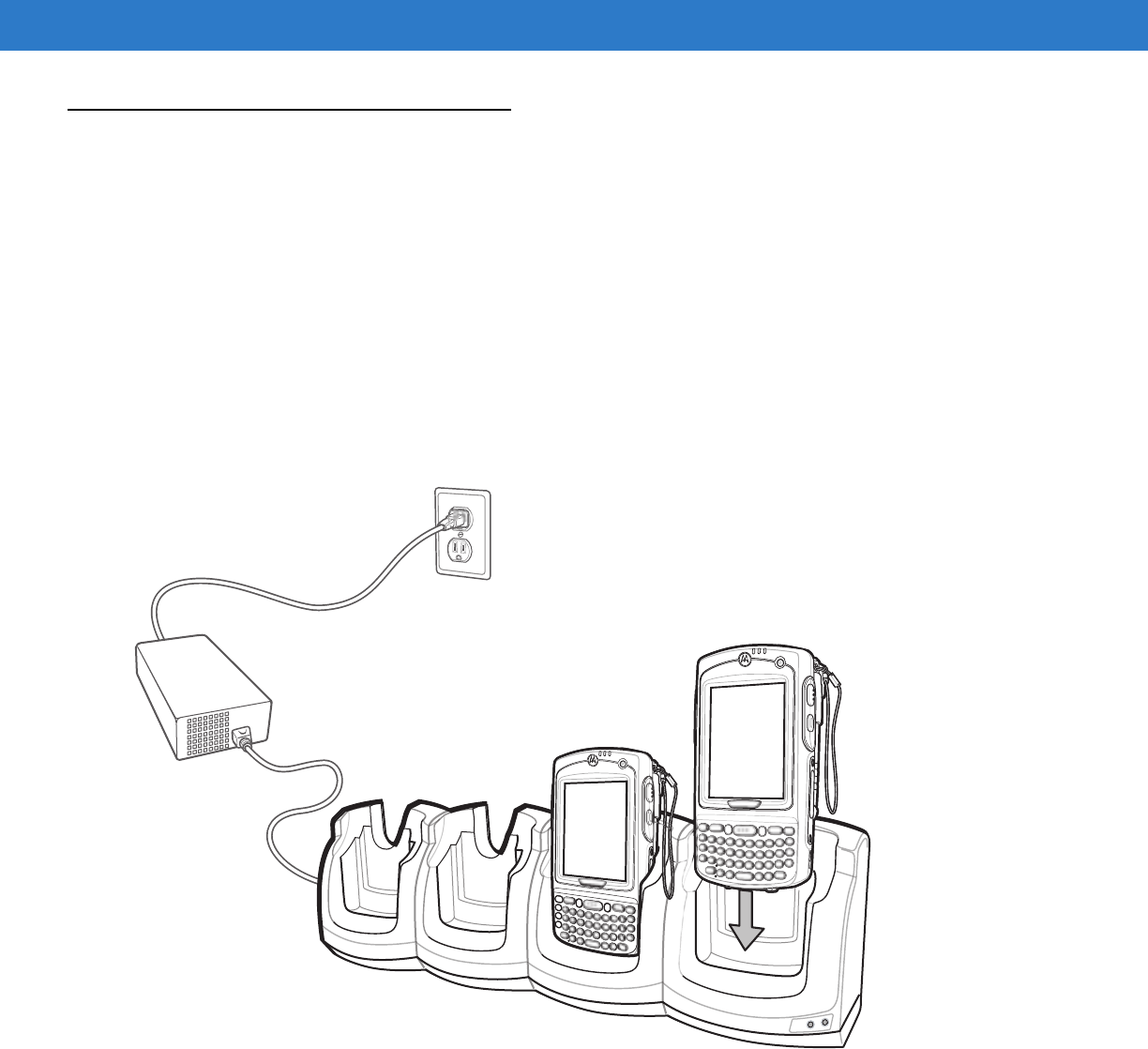
Four Slot Ethernet Cradle
This section describes how to set up and use a Four Slot Ethernet cradle with the MC75A. For cradle
communication setup procedures refer to the MC75A Integrator Guide.
The Four Slot Ethernet cradle:
•
Provides 5.4 VDC power for operating the MC75A.
•
Connects the MC75A (up to four) to an Ethernet network.
•
Simultaneously charges up to four MC75A devices.
Charging
Insert the MC75A into a slot to begin charging.
Figure 7-3
MC75A Battery Charging
Battery Charging Indicators
The MC75A’s charge LED shows the status of the battery charging in the MC75A. See Table 1-2 on page 1-7 for
charging status indications.
The 3600 mAh battery fully charges in less than five hours and the 4800 mAh battery fully charges in less than
seven hours.
DRAFT

7 - 6 MC75A Enterprise Digital Assistant User Guide
Charging Temperature
Charge batteries in temperatures from 0°C to 40°C (32°F to 104°F). Charging is intelligently controlled by the
MC75A.
To accomplish this, for small periods of time, the MC75A or accessory alternately enables and disables battery
charging to keep the battery at acceptable temperatures. The MC75A or accessory indicates when charging is
disabled due to abnormal temperatures via its LED. See Table 1-2 on page 1-7.
DRAFT
Accessories 7 - 7
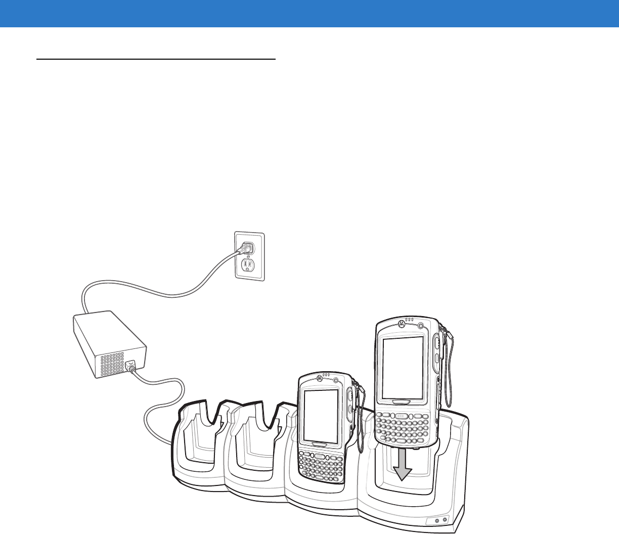
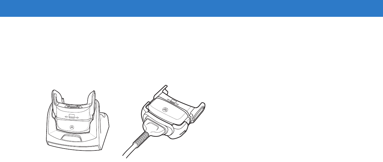
Four Slot Charge Only Cradle
This section describes how to set up and use a Four Slot Charge Only cradle with the MC75A.
The Four Slot Charge Only cradle:
•
Provides 5.4 VDC power for operating the MC75A.
•
Simultaneously charges up to four MC75A devices.
Charging
Insert the MC75A into a slot to begin charging.
Figure 7-4
MC75A Battery Charging
Battery Charging Indicators
The MC75A’s charge LED shows the status of the battery charging in the MC75A. See Table 1-2 on page 1-7 for
charging status indications.
The 3600 mAh battery fully charges in less than five hours and the 4800 mAh battery fully charges in less than
seven hours.
Charging Temperature
Charge batteries in temperatures from 0°C to 40°C (32°F to 104°F). Charging is intelligently controlled by the
MC75A.
DRAFT

7 - 8 MC75A Enterprise Digital Assistant User Guide
To accomplish this, for small periods of time, the MC75A or accessory alternately enables and disables battery
charging to keep the battery at acceptable temperatures. The MC75A or accessory indicates when charging is
disabled due to abnormal temperatures via its LED. See Table 1-2 on page 1-7.
DRAFT
Accessories 7 - 9
VCD7X00 Vehicle Cradle
This section describes how to use a VCD7X00 vehicle cradle with the MC75A. For cradle installation and
communication setup procedures refer to the MC75A Integrator Guide.
Once installed in a vehicle, the cradle:
•
holds the MC75A securely in place
•
provides power for operating the MC75A
•
provides a serial port for data communication between an MC75A and an external device (e.g., a printer)
•
re-charges the battery in the MC75A
•
re-charges a 3600 mAh or 4800 mAh spare battery.
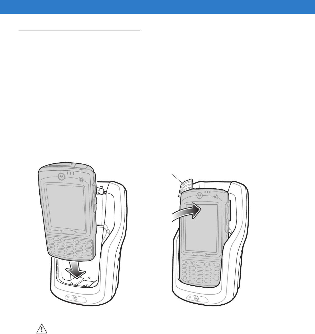
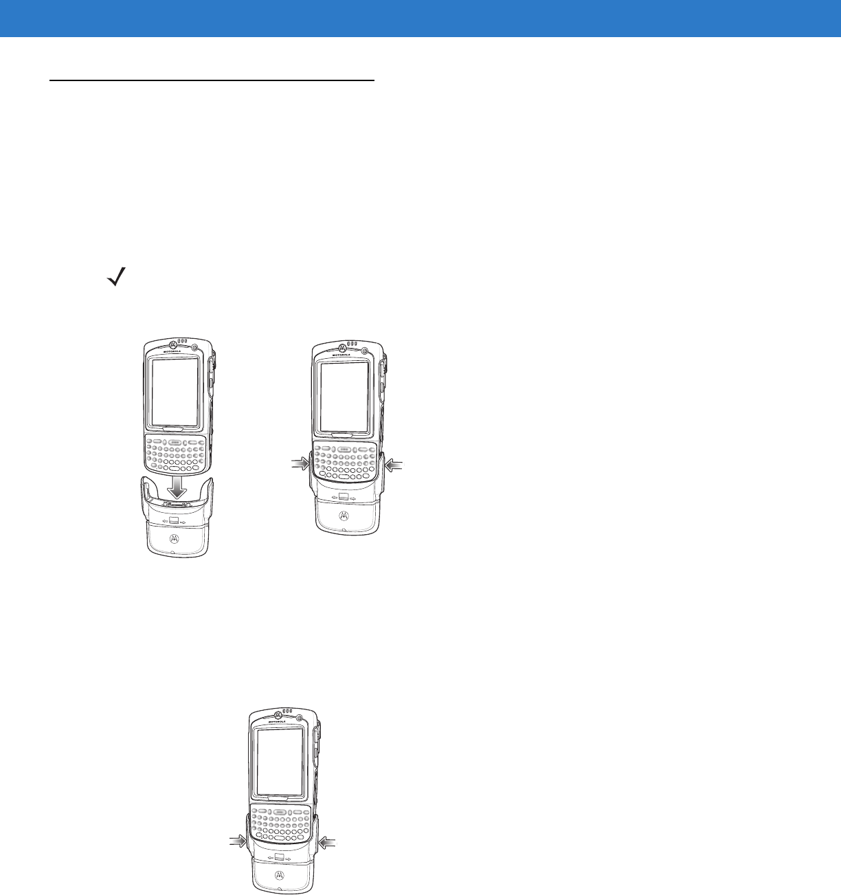
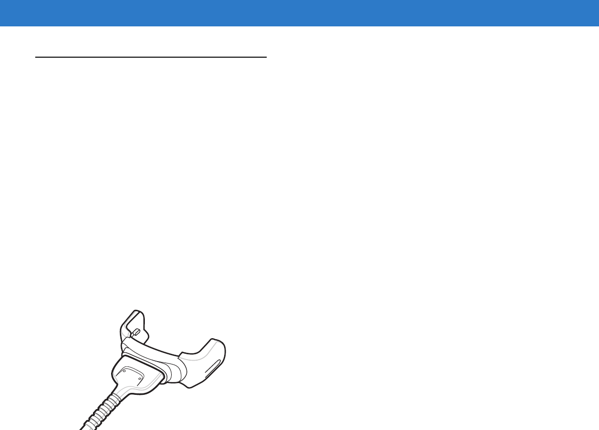
Charging the MC75A Battery
Insert the MC75A into the vehicle cradle to begin charging. A click indicates that the MC75A button release locking
mechanism is enabled and the MC75A is locked in place.
Figure 7-5
MC75A Battery Charging
Release Lever
CAUTION Ensure the MC75A is fully inserted in the cradle. Lack of proper insertion may result in property damage
or personal injury. Motorola is not responsible for any loss resulting from the use of the products while
driving.
DRAFT
7 - 10 MC75A Enterprise Digital Assistant User Guide
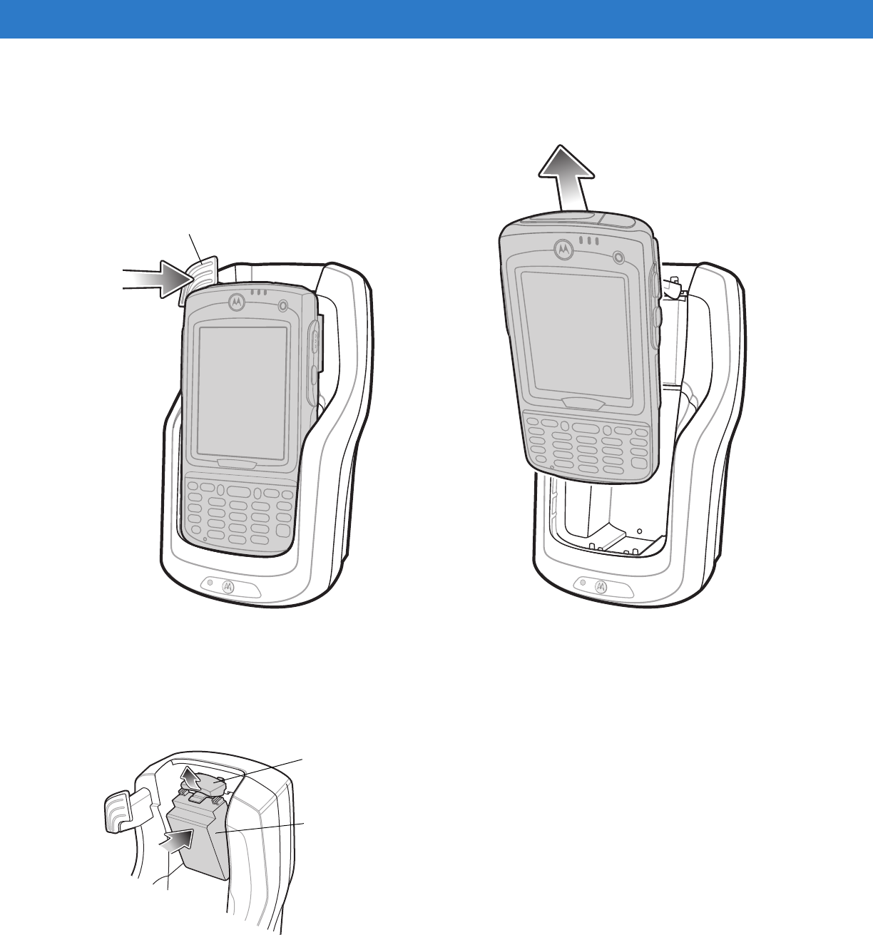
Removing the MC75A
To remove the MC75A, hold back the release lever on the cradle and pull the MC75A up and out of the cradle.
Figure 7-6
Removing the MC75A
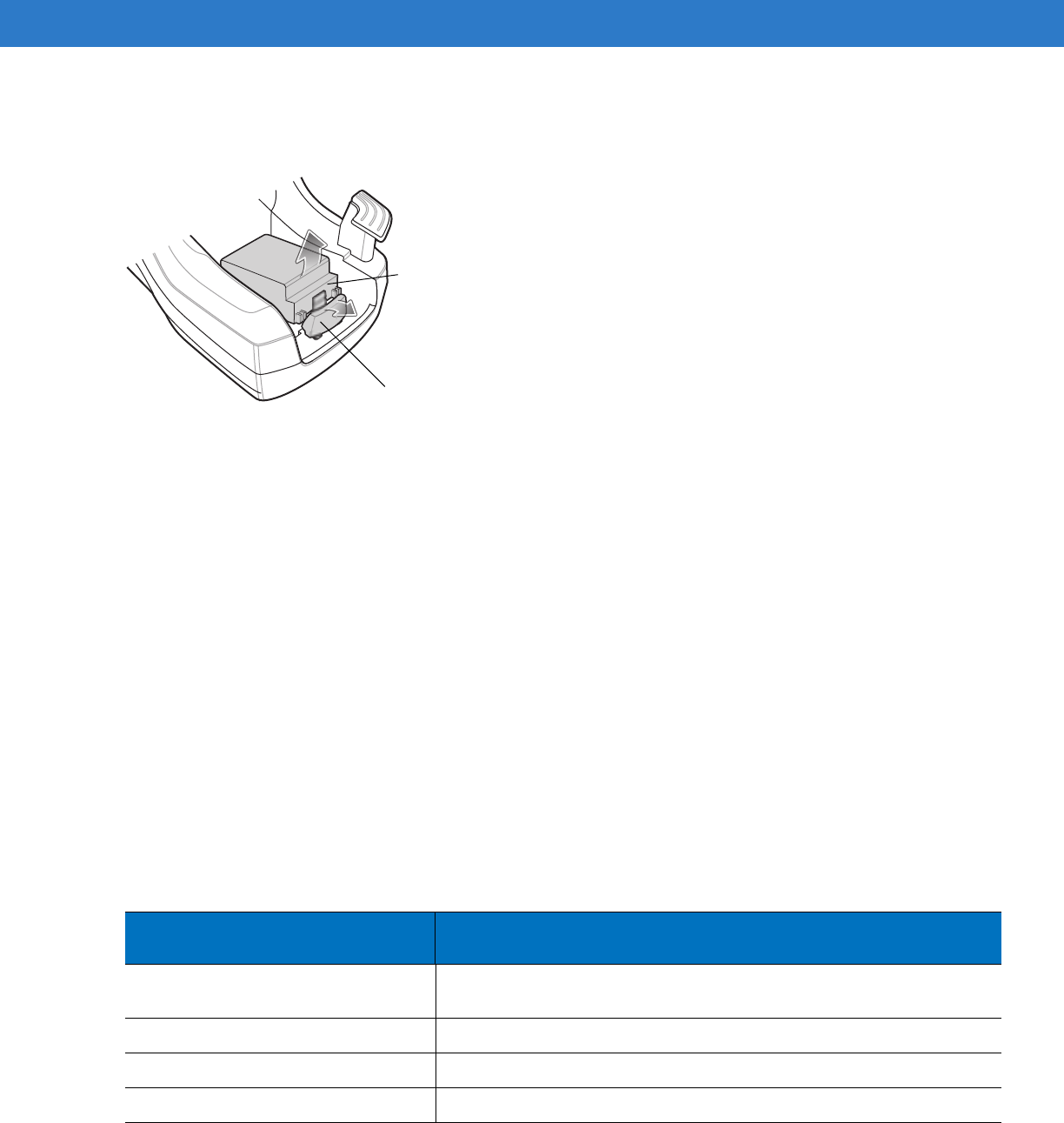
Charging the Spare Battery
Insert a spare battery to begin charging:
1. Lift the battery release lever.
Figure 7-7
Inserting the Spare Battery
2. Insert the spare battery in the spare battery charging slot in the cradle with the charging contacts facing up and
to the rear of the cradle.
Release Lever
Battery
Battery Release Lever
DRAFT
Accessories 7 - 11
3. Release the battery release lever. The battery release lever locks the spare battery into place.
To remove a spare battery, hold back the battery release lever and lift the battery from the spare battery slot.
Figure 7-8
Removing the Spare Battery
Battery Charging Indicators
The Vehicle Cradle charges the MC75A’s main battery and a spare battery simultaneously.
The MC75A’s charge LED indicates the status of the battery charging in the MC75A. See Table 1-2 on page 1-7 for
charging status indications.
The spare battery charging LED on the cradle indicates the status of the spare battery charging in the cradle. See
Table 7-3 for charging status indications.
The 3600 mAh battery fully charges in less than five hours and the 4800 mAh battery fully charges in less than
seven hours.
Charging Temperature
Charge batteries in temperatures from 0°C to 40°C (32°F to 104°F). Charging is intelligently controlled by the
MC75A.
To accomplish this, for small periods of time, the MC75A or accessory alternately enables and disables battery
charging to keep the battery at acceptable temperatures. The MC75A or accessory indicates when charging is
disabled due to abnormal temperatures via its LED. See Table 1-2 on page 1-7 and Table 7-3.
Battery Release Lever
Battery
Table 7-3
Vehicle Cradle Spare Battery LED Charging Indicators
Spare Battery LED
(on cradle) Indication
Off Battery is not charging; battery is not inserted correctly in the cradle;
cradle is not powered
Slow Blinking Amber Spare battery is charging.
Solid Amber Charging complete.
Fast Blinking Amber Charging error.
DRAFT
7 - 12 MC75A Enterprise Digital Assistant User Guide
Four Slot Battery Charger
This section describes how to use the Four Slot Battery Charger to charge up to four MC75A batteries.
MC75A Battery Shim Installation
Before charging a spare battery, snap the MC75A shim into the battery slot as shown in Figure 7-9.
Figure 7-9
MC75A Battery Shim Installation
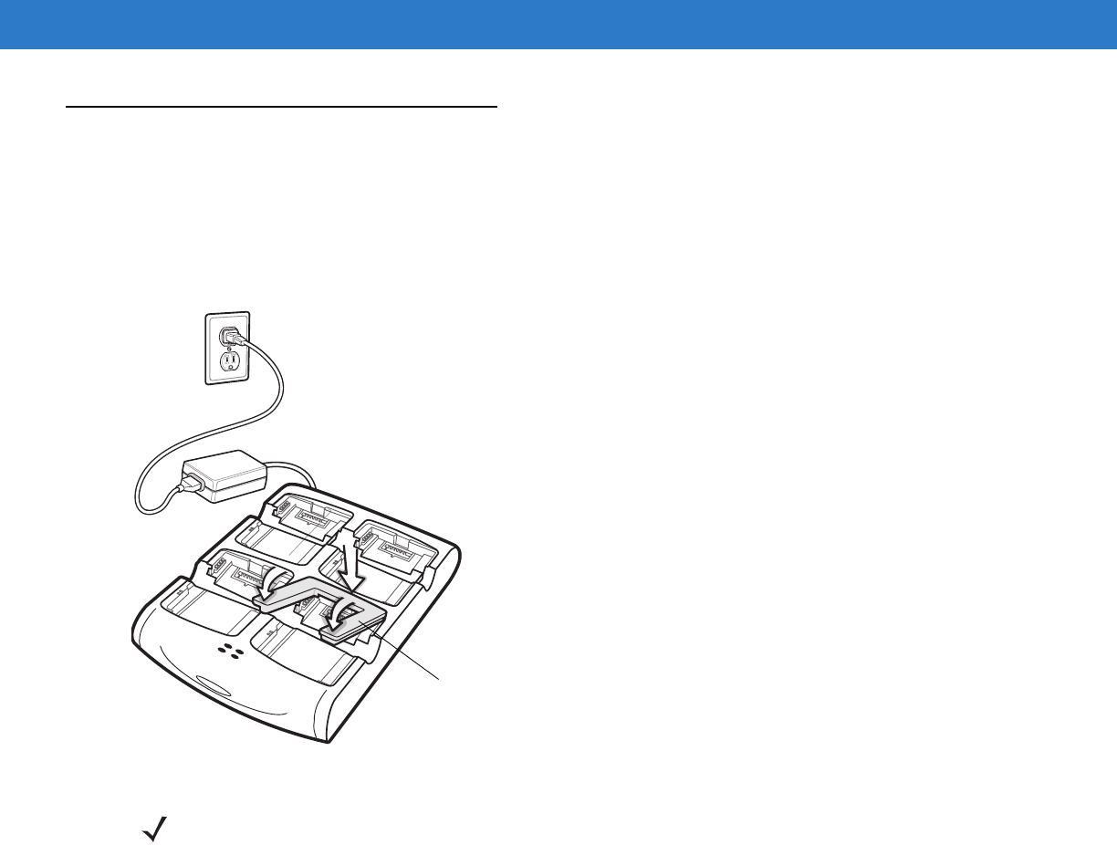
Spare Battery Charging
1. Connect the charger to a power source.
2. Insert the spare battery into a spare battery charging well and gently press down on the battery to ensure
proper contact.
Shim
NOTE To purchase additional shims, contact your local account manager or Motorola, Inc. Part number:
KT-76490-01R.
DRAFT
Accessories 7 - 13
Figure 7-10
Four Slot Battery Charger
Battery Charging Indicators
The charger has an amber LED for each battery charging well. See Table 7-4 for charging status indications. The
3600 mAh battery fully charges in less than five hours and the 4800 mAh battery fully charges in less than seven
hours.
Charging Temperature
Charge batteries in temperatures from 0°C to 40°C (32°F to 104°F). Charging is intelligently controlled by the
MC75A.
To accomplish this, for small periods of time, the charger alternately enables and disables battery charging to keep
the battery at acceptable temperatures. The charger indicates when charging is disabled due to abnormal
temperatures via its LED. See Table 7-4.
Spare Battery
Charging LEDs (4)
Spare Battery
Table 7-4
Spare Battery LED Charging Indicators
LED Indication
Off No spare battery in slot; battery is not charging; battery is not inserted correctly in
the charger; charger is not powered.
Slow Blinking Amber Spare battery is charging.
Solid Amber Charging complete.
Fast Blinking Amber Charging error.
DRAFT
7 - 14 MC75A Enterprise Digital Assistant User Guide
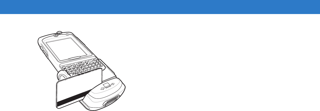
Magnetic Stripe Reader (MSR)
This section describes how to set up and use the snap-on MSR with the MC75A. The MSR snaps on to the bottom
of the MC75A and removes easily when not in use.
When attached to the MC75A, the MSR allows the MC75A to capture data from magnetic stripe cards. To
download MSR data capture software, visit the Motorola web site at http://www.symbol.com/support.
With the MSR attach, the MC75A can still be charged by placing the MC75A with MSR into a cradle or connecting
to a charging cable.
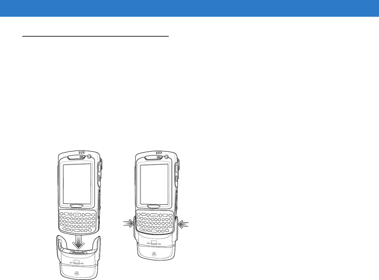
Attaching and Removing the MSR
To attach, slide the MSR onto the bottom of the MC75A and secure by snapping the arms into the MC75A housing.
Figure 7-11
MSR Installation
To remove the MSR open the arms and pull the MSR from the MC75A.
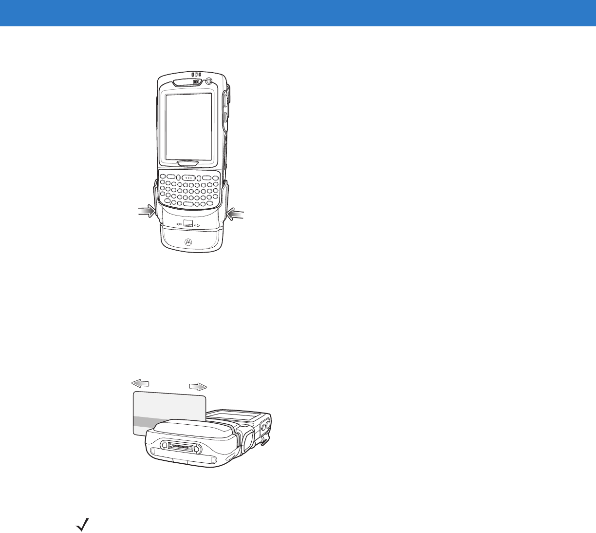
Using the MSR
Install an MSR enabled application onto the MC75A.
To use the MSR:
1. Attach the MSR to the MC75A.
2. Power on the MC75A.
3. Launch the MSR application.
4. Swipe the magnetic stripe card through the MSR, with the magnetic stripe on the card facing down. Swipe the
card in either direction, from left to right or from right to left. For best results, gently press down on the card
while swiping to ensure contact with the bottom of the reader.
NOTE When attaching a cable with a cup connector through the MSR to charge the device, you cannot swipe
cards.
DRAFT
Accessories 7 - 15
Figure 7-12
Magnetic Stripe Card Swiping
5. The application indicates if the data has been read correctly.
DRAFT
7 - 16 MC75A Enterprise Digital Assistant User Guide
Debit Card Reader
The DCR7X00-100R Debit Card Reader (DCR) snaps onto the bottom of the MC70/MC75A mobile computer to
allow easy data capture with the swipe of a magnetic stripe card and personal identification number (PIN) entry
using a numeric keypad. This guide describes how to install and use the DCR.
Getting Started
When using the DCR for the first time, charge the DCR in a cradle for a minimum of three hours.
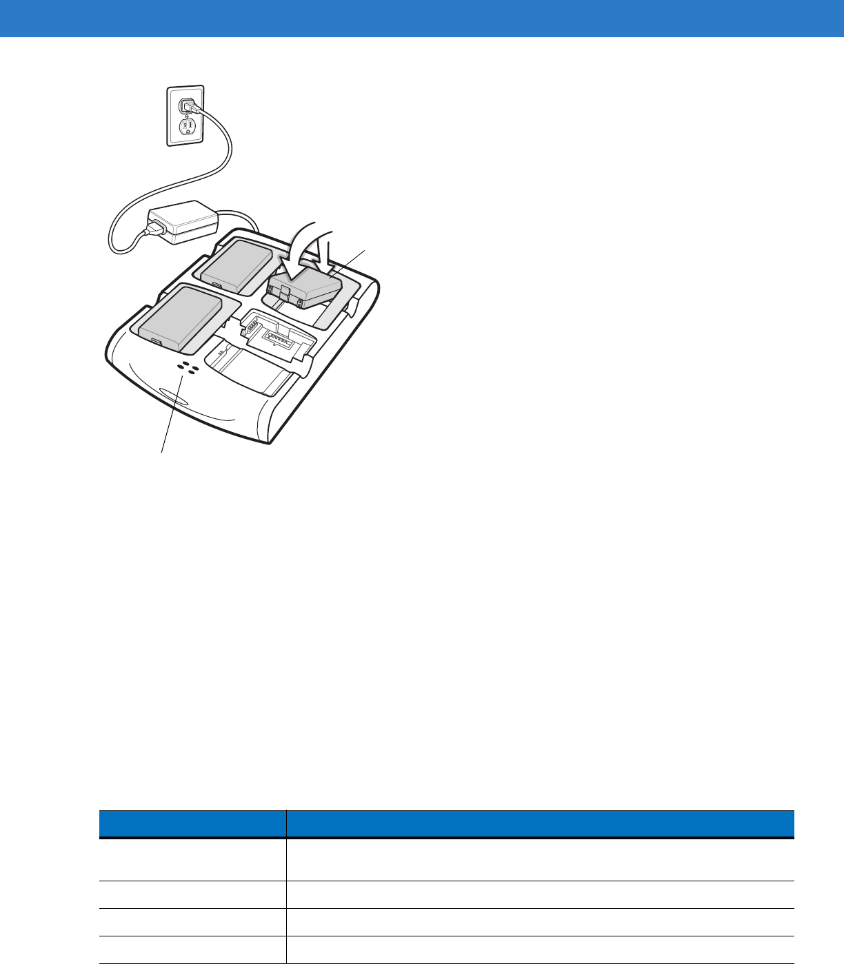
Installation
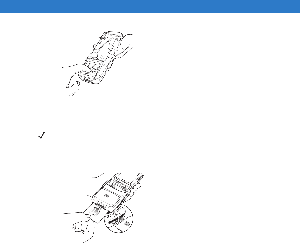
1. Align the DCR with the bottom of the MC75A and push up until the locking tabs snap into place.
Figure 7-13
DCR Installation
2. Pull on the DCR to ensure it is securely connected to the MC75A.
Removal
To remove the DCR from the MC75A, push in the bottom of the two locking tabs and pull the DCR from the MC75A.
DRAFT
Accessories 7 - 17
Figure 7-14
DCR Removal
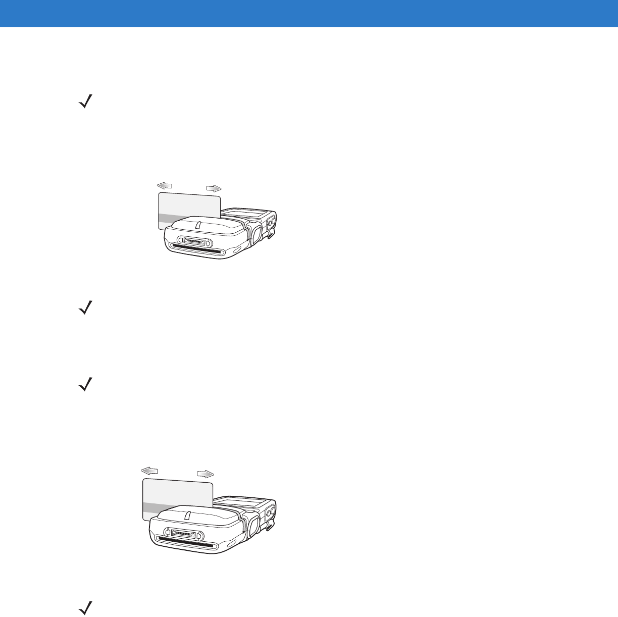
Credit Card Transactions
Launch a transaction application on the MC75A. In the application, select Credit Card transaction.
Swipe the credit card through the magnetic stripe reader (MSR) slot, orienting the magnetic stripe as shown. Data
encoded on the credit card is captured and, depending on the application, may display in an application data field.
Figure 7-15
Swipe Card
Debit Card Transactions
Launch a transaction application on the MC75A. In the application, select Debit Card transaction.
Swipe the debit card through the MSR slot, orienting the magnetic stripe as shown. Data encoded on the debit card
is captured and, depending on the application, may display in an application data field.
NOTE Swipe the card in either direction, from left to right, or right to left. For best results, gently press down on the
card while swiping to ensure contact with the bottom of the slot.
DRAFT
7 - 18 MC75A Enterprise Digital Assistant User Guide
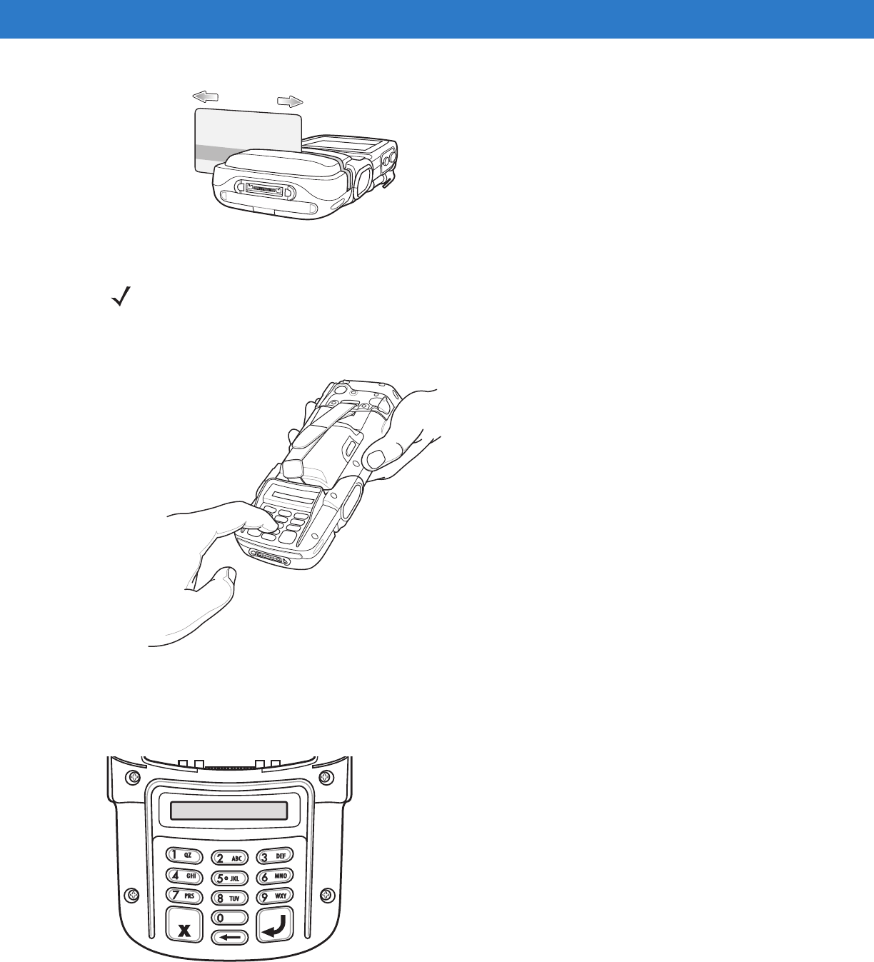
Figure 7-16
Swipe Card
Turn the MC75A over and present the DCR keypad to the customer. The customer enters their PIN following the
instructions on the DCR display.
Figure 7-17
Enter PIN on DCR
Keypad
The back of the DCR contains a display and a numeric keypad for entering data.
Figure 7-18
DCR Keypad
NOTE Swipe the card in either direction, from left to right, or right to left. For best results, gently press down on the
card while swiping to ensure contact with the bottom of the slot.
DRAFT
Accessories 7 - 19
Display Messages
The follow messages may appear on the DCR display:
ENTER PIN - A PIN is required to complete the transaction.
PIN ERR - The entered PIN is not between 4 and 12 characters.
CANCELED - The transaction was cancelled by the user.
COMPLETE - The transaction was completed.
KEYCLEAR - The DCR was tampered with or the battery completely discharged. The DCR must have the key
re-injected. See your system administrator.
BATT OK - Battery is significantly charged.
BATT LOW - Battery charge is low. Re-charge as soon as possible.
STAND BY - DCR is performing a firmware check. This occurs if it has been powered off for more than 24 hours.
Check the DCR Battery Level
When the DCR is not used for extended periods of time or in storage it must be charged periodically to maintain the
battery charge. Motorola recommends charging the DCR once every three months.
If the DCR battery fully discharges the debit function will be inoperable but the MSR will still function for credit card
transactions. Return the DCR for service.
To check the battery level:
1. Remove the DCR from the MC75A.
2. Press and hold the 5 key until the battery status displays on the DCR display.
•
BATT OK - Battery is significantly charged
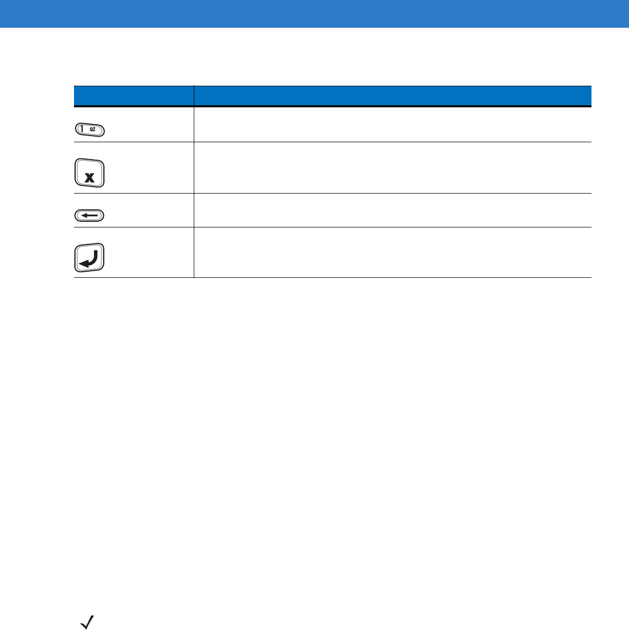
Table 7-5
Keypad Key Descriptions
Key Description
Numeric Used to enter PIN.
Cancel Cancels the current transaction.
Clear Clears the entered data.
Enter Submits the entered data.
NOTE While the DCR is being used in normal operation (application is accessing the DCR port), the DCR charges
from the MC75A.
DRAFT
7 - 20 MC75A Enterprise Digital Assistant User Guide
•
BATT LOW - Battery charge is low.
If BATT LOW displays, charge the DCR for approximately three hours.
To charge the DCR, place it in a cradle or connect it to a charging cable. The DCR also charges when connected to
the MC75A and the transaction application is running.
Figure 7-19
Charging the DCR
DRAFT
Accessories 7 - 21
Snap-on Mobile Payment Module with Chip and PIN
The DCR7X00-200R Snap-on Mobile Payment Module with Chip and PIN smart card reader snaps onto the
bottom of the MC75A mobile computer to allow easy data capture with magnetic stripe cards, EMV compliant Chip
and PIN cards and personal identification number (PIN) entry using a numeric keypad. This guide describes how to
install and use the module.
Installation
1. Align the module with the bottom of the MC75A and push up until the locking tabs snap into place.
Figure 7-20
Attach Module to MC75A
2. Pull on the module to ensure it is securely connected to the MC75A.
Removal
To remove the module from the MC75A, push in the bottom of the two locking tabs and pull the module from the
MC75A.
Figure 7-21
Press Latches In to Lock
NOTE The module only functions when attached to the MC70/MC75.
DRAFT
7 - 22 MC75A Enterprise Digital Assistant User Guide
Credit Card Transactions
Launch a transaction application on the MC75A. In the application, select Credit Card transaction.
Swipe the credit card through the magnetic stripe reader (MSR) slot, orienting the magnetic stripe as shown. Data
encoded on the credit card is captured and, depending on the application, may display in an application data field.
Figure 7-22
Swipe Card
Debit Card Transactions
Launch a transaction application on the MC75A. In the application, select Debit Card transaction.
Swipe the debit card through the MSR slot, orienting the magnetic stripe as shown. Data encoded on the debit card
is captured and, depending on the application, may display in an application data field.
Figure 7-23
Swipe Card
Turn the MC75A over and present the keypad to the customer. The customer enters their PIN following the instructions on the display.
NOTE Credit Card transactions will function without an encryption key injected but will not function if a tamper event
occurs.
NOTE Swipe the card in either direction, from left to right, or right to left. For best results, gently press down on the
card while swiping to ensure contact with the bottom of the slot.
NOTE Debit Card transactions will only function with an encryption key injected. It will not function if a tamper event
occurs.
NOTE Swipe the card in either direction, from left to right, or right to left. For best results, gently press down on the card while
swiping to ensure contact with the bottom of the slot.
DRAFT
Accessories 7 - 23
Figure 7-24
Enter PIN
Chip and PIN Transactions
Launch a transaction application on the MC75A. In the application, select Chip and PIN transaction.
Customer inserts the Chip and Pin card into the slot, orienting the card with the contacts facing down and toward
the DCR keypad.
Figure 7-25
Insert Card
Customer turns the MC75A over, and enters their PIN following the instructions on the display.
Customer removes the card when transaction is complete.
Keypad
The back of the module contains a display and a numeric keypad for entering data.
NOTE Chip and PIN transactions will function without an encryption key injected but will not function if a tamper event
occurs.
DRAFT
7 - 24 MC75A Enterprise Digital Assistant User Guide
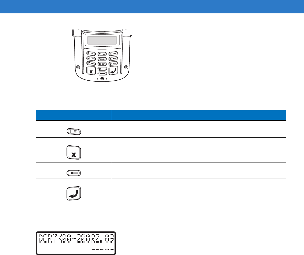
Figure 7-26
Keypad
Display Messages
After connecting the module to the MC70/MC75 and an application opens the COM port, the following displays:
.
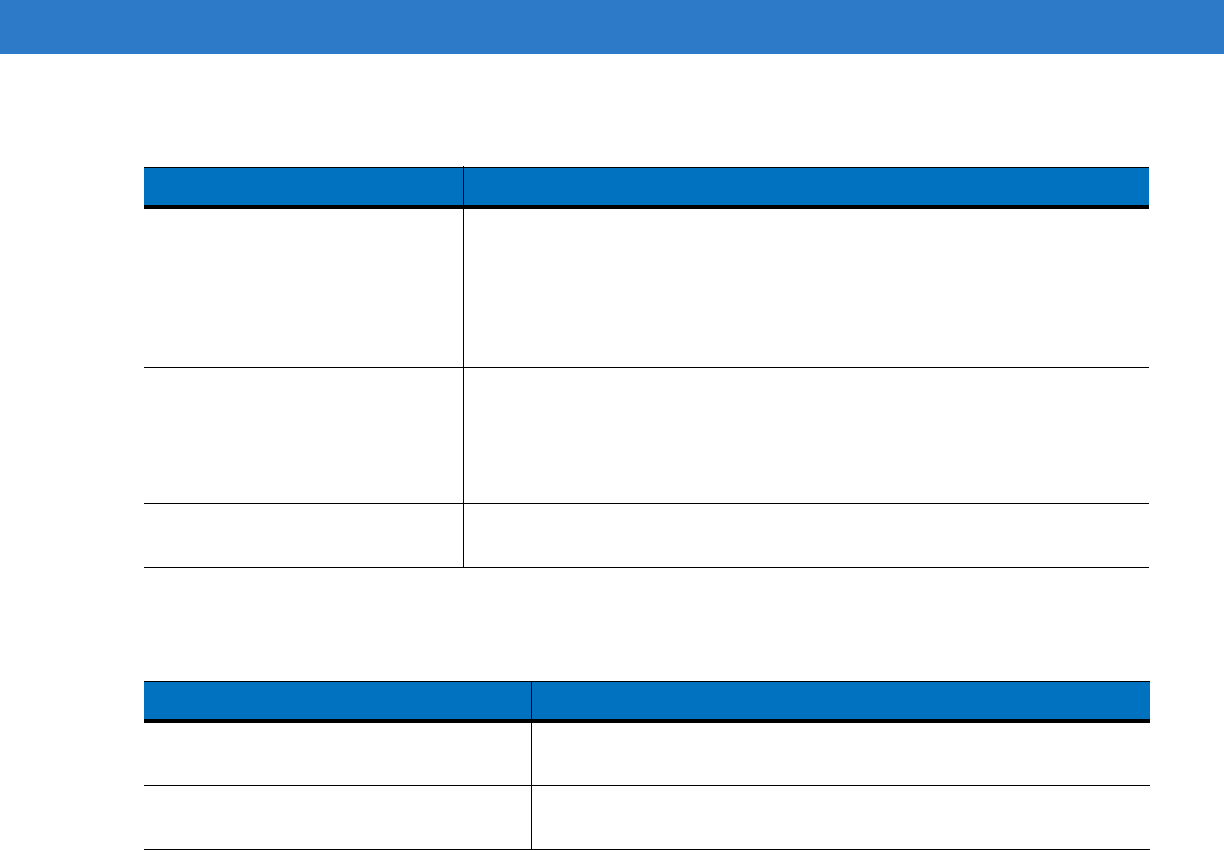
Figure 7-27
Display
Line 1 indicates the model number and the firmware version. The firmware version displays after the model
number. In this example the firmware version is 0.09.
Line 2 indicates the keyload code. Each characters of the keyload code represents a different key type.
Table 7-6
Keypad Button Descriptions
Key Description
Numeric Used to enter PIN.
Cancel (Red) Cancels the current transaction.
Clear (Yellow) Clears the entered data.
Enter (Green) Submits the entered data.
DRAFT
Accessories 7 - 25
The follow messages may appear on the display:
Table 7-7
Keyload Codes
Display Operating Status
D - - - -
D M M - -
D - - M M
- M M - -
- - - M M
- - - - -
Normal
d - - - -
d m m - -
d - - m m
- m m - -
- - - m m
Return to key injection facility.
* * * * *
Blank display
Return to Motorola for service.
Table 7-8
Display Messages
Message Description
Line 1:
Line 2: Enter PIN Instructs the user to enter their PIN.
Line 1: PIN
Line 2: ENT to Accept Displays “*” as PIN is entered and instructs the user to press enter key
when done.
DRAFT
7 - 26 MC75A Enterprise Digital Assistant User Guide
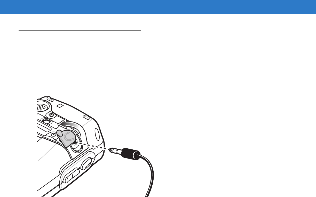
Headset
Use the headset to communicate via Voice-Over-IP (VOIP) or for audio playback and telephony applications. To
connect the headset, remove the plug from the headset jack at the top of the MC75A and insert the headset
connector. Contact a Motorola representative for compatible headsets.
For best performance, Motorola recommends a 2.5mm jack headset, p/n 50-11300-050R.
Figure 7-28
Headset Connection
DRAFT
Accessories 7 - 27
Cables
This section describes how to set up and use the cables. The cables are available with a variety of connection
capabilities.
The following communication/charge cables are available:
•
Serial (RS232) Charge cable (9-pin D female with power input receptacle)
•
USB Client Charge cable (standard-A connector and a barrel receptacle for power)
•
Auto charge cable
•
DEX cable
•
Modem inverter cable
•
Charge only cable.
The following printer cables are available directly from Motorola:
•
O’Neil Printer cable
•
Zebra Printer cable.
Figure 7-29
Cables
Communication/charge cables:
•
Provide the MC75A with operating and charging power when used with the Motorola approved power supply.
•
Synchronize information between the MC75A and a host computer. With customized or third party software,
it can also synchronize the MC75A with corporate databases.
•
Provide serial connection through the serial pass-through port for communication with a serial device, such
as a host computer. For communication setup procedures, refer to the MC75A Integrator Guide.
•
Provide USB connection through the USB pass-through port for communication with a USB device, such as
a host computer. For communication setup procedures, refer to the MC75A Integrator Guide.
Dedicated printer cables provide communication with a printer.
Battery Charging and Operating Power
The communication/charge cables can charge the MC75A battery and supply operating power.
To charge the MC75A battery:
1. Connect the communication/charge cable power input connector to the Motorola approved power source.
DRAFT

7 - 28 MC75A Enterprise Digital Assistant User Guide
2. Slide the bottom of the MC75A into the connector end of the communication/charge cable and gently press in
until it latches into the MC75A. The MC75A amber Charge LED indicates the MC75A battery charging status.
The 3600 mAh standard battery charges in less than five hours and the 4800 mAh standard battery charges in
less than seven hours. See Table 1-2 on page 1-7 for charging status indications.
3. When charging is complete, remove the cable by gently pulling the MC75A and the cable apart.
LED Charge Indications
The amber Charge LED on the MC75A indicates battery charging status. See Table 1-2 on page 1-7 for charging
status indications.
Charging Temperature
Charge batteries in temperatures from 0°C to 40°C (32°F to 104°F). Charging is intelligently controlled by the
MC75A.
To accomplish this, for small periods of time, the MC75A or accessory alternately enables and disables battery
charging to keep the battery at acceptable temperatures. The MC75A or accessory indicates when charging is
disabled due to abnormal temperatures via its LED. See Table 1-2 on page 1-7.4
DRAFT

Chapter 8 Maintenance & Troubleshooting
Introduction
This chapter includes instructions on cleaning and storing the MC75A, and provides troubleshooting solutions for
potential problems during MC75A operation.
Maintaining the MC75A
For trouble-free service, observe the following tips when using the MC75A:
•
Do not scratch the screen of the MC75A. When working with the MC75A, use the supplied stylus or
plastic-tipped pens intended for use with a touch-sensitive screen. Never use an actual pen or pencil or other
sharp object on the surface of the MC75A screen.
•
A screen protector, p/n KT-67525-01R, is applied to the MC75A. Motorola recommends using this to
minimize wear and tear. Screen protectors enhance the usability and durability of touch screen displays.
Benefits include:
•Protection from scratches and gouges
•Durable writing and touch surface with tactile feel
•Abrasion and chemical resistance
•Glare reduction
•Keeping the device’s screen looking new
•Quick and easy installation.
•
The touch-sensitive screen of the MC75A is glass. Do not to drop the MC75A or subject it to strong impact.
•
Protect the MC75A from temperature extremes. Do not leave it on the dashboard of a car on a hot day, and
keep it away from heat sources.
•
Do not store or use the MC75A in any location that is dusty, damp, or wet.
•
Use a soft lens cloth to clean the MC75A. If the surface of the MC75A screen becomes soiled, clean it with a
soft cloth moistened with a diluted window-cleaning solution.
•
Periodically replace the rechargeable battery to ensure maximum battery life and product performance.
Battery life depends on individual usage patterns.
DRAFT
8 - 2 MC75A Enterprise Digital Assistant User Guide
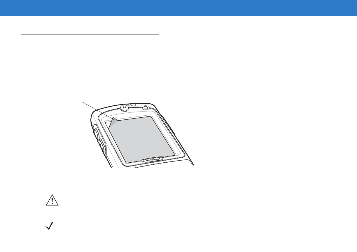
Removing the Screen Protector
A screen protector is applied to the MC75A. Motorola recommends using this to minimize wear and tear. Screen
protectors enhance the usability and durability of touch screen displays.
To remove the screen protector, lift the corner using a thin plastic card, such as a credit card, then carefully lift it off
the display.
Figure 8-1
Removing the Screen Protector
Battery Safety Guidelines
•
The area in which the units are charged should be clear of debris and combustible materials or chemicals.
Particular care should be taken where the device is charged in a non commercial environment.
•
Follow battery usage, storage, and charging guidelines found in the user's guide.
•
Improper battery use may result in a fire, explosion, or other hazard.
•
To charge the mobile device battery, the battery and charger temperatures must be between +32 ºF and
+104 ºF (0 ºC and +40 ºC)
•
Do not use incompatible batteries and chargers. Use of an incompatible battery or charger may present a risk
of fire, explosion, leakage, or other hazard. If you have any questions about the compatibility of a battery or a
charger, contact Motorola Enterprise Mobility support.
•
For devices that utilize a USB port as a charging source, the device shall only be connected to products that
bear the USB-IF logo or have completed the USB-IF compliance program.
•
To enable authentication of an approved battery, as required by IEEE1725 clause 10.2.1, all batteries will
carry a Motorola hologram. Do not fit any battery without checking it has the Motorola authentication
hologram.
•
Do not disassemble or open, crush, bend or deform, puncture, or shred.
Lift Screen
Protector
Corner
CAUTION Do not use a sharp object to remove the protector. Doing so can damage the display.
NOTE Not using a screen protector can affect warranty coverage. To purchase replacement protectors, contact your
local account manager or Motorola, Inc. These include screen protector installation instructions. Part number:
KT-67525-01R Screen Protector 3/pk.
DRAFT
Maintenance & Troubleshooting 8 - 3
•
Severe impact from dropping any battery-operated device on a hard surface could cause the battery to
overheat.
•
Do not short circuit a battery or allow metallic or conductive objects to contact the battery terminals.
•
Do not modify or remanufacture, attempt to insert foreign objects into the battery, immerse or expose to water
or other liquids, or expose to fire, explosion, or other hazard.
•
Do not leave or store the equipment in or near areas that might get very hot, such as in a parked vehicle or
near a radiator or other heat source. Do not place battery into a microwave oven or dryer.
•
Battery usage by children should be supervised.
•
Please follow local regulations to promptly dispose of used re-chargeable batteries.
•
Do not dispose of batteries in fire.
•
Seek medical advice immediately if a battery has been swallowed.
•
In the event of a battery leak, do not allow the liquid to come in contact with the skin or eyes. If contact has
been made, wash the affected area with large amounts of water and seek medical advice.
•
If you suspect damage to your equipment or battery, contact Motorola Enterprise Mobility support to arrange
for inspection.
Cleaning
Materials Required
•
Alcohol wipes
•
Lens tissue
•
Cotton tipped applicators
•
Isopropyl alcohol
•
Can of compressed air with a tube.
Cleaning the MC75A
Housing
Using the alcohol wipes, wipe the housing including keys and in-between keys.
WARNING!Avoid exposing this product to contact with hot oil or other flammable liquids. If such exposure
occurs, unplug the device and clean the product immediately in accordance with these guidelines.
CAUTION Always wear eye protection.
Read warning label on compressed air and alcohol product before using.
If you have to use any other solution for medical reasons please contact Motorola for more information.
DRAFT
8 - 4 MC75A Enterprise Digital Assistant User Guide
Display
The display can be wiped down with the alcohol wipes, but care should be taken not to allow any pooling of liquid
around the edges of the display. Immediately dried the display with a soft, non-abrasive cloth to prevent streaking.
Scanner Exit Window
Wipe the scanner exit window periodically with a lens tissue or other material suitable for cleaning optical material
such as eyeglasses.
Connector
1. Remove the main battery from mobile computer. See Replacing the Main Battery on page 1-9.
2. Close battery door.
3. Dip the cotton portion of the cotton tipped applicator in isopropyl alcohol.
4. Rub the cotton portion of the cotton tipped applicator back-and-forth across the connector on the bottom of the
MC75A. Do not leave any cotton residue on the connector.
5. Repeat at least three times.
6. Use the cotton tipped applicator dipped in alcohol to remove any grease and dirt near the connector area.
7. Use a dry cotton tipped applicator and repeat steps 4 through 6.
8. Spray compressed air on the connector area by pointing the tube/nozzle about ½ inch away from the surface.
9. Inspect the area for any grease or dirt, repeat if required.
Cleaning Cradle Connectors
To clean the connectors on a cradle:
1. Remove the DC power cable from the cradle.
2. Dip the cotton portion of the cotton tipped applicator in isopropyl alcohol.
3. Rub the cotton portion of the cotton tipped applicator along the pins of the connector. Slowly move the
applicator back-and-forth from one side of the connector to the other. Do not let any cotton residue on the
connector.
4. All sides of the connector should also be rubbed with the cotton tipped applicator.
5. Spray compressed air in the connector area by pointing the tube/nozzle about ½ inch away from the surface.
6. Ensure that there is no lint left by the cotton tipped applicator, remove lint if found.
7. If grease and other dirt can be found on other areas of the cradle, use lint free cloth and alcohol to remove.
CAUTION Do not point nozzle at yourself and others, ensure the nozzle or tube is away from your face.
CAUTION Do not point nozzle at yourself and others, ensure the nozzle or tube is away from your face.
DRAFT
Maintenance & Troubleshooting 8 - 5
8. Allow at least 10 to 30 minutes (depending on ambient temperature and humidity) for the alcohol to air dry
before applying power to cradle.
If the temperature is low and humidity is high, longer drying time is required. Warm temperature and dry
humidity requires less drying time.
Cleaning Frequency
The cleaning frequency is up to the customer’s discretion due to the varied environments in which the mobile
devices are used. They may be cleaned as frequently as required. However when used in dirty environments it
may be advisable to periodically clean the scanner exit window to ensure optimum scanning performance.
Troubleshooting
MC75A
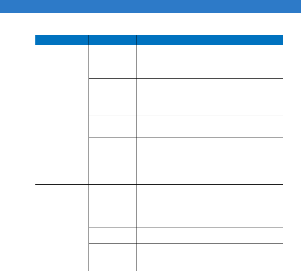
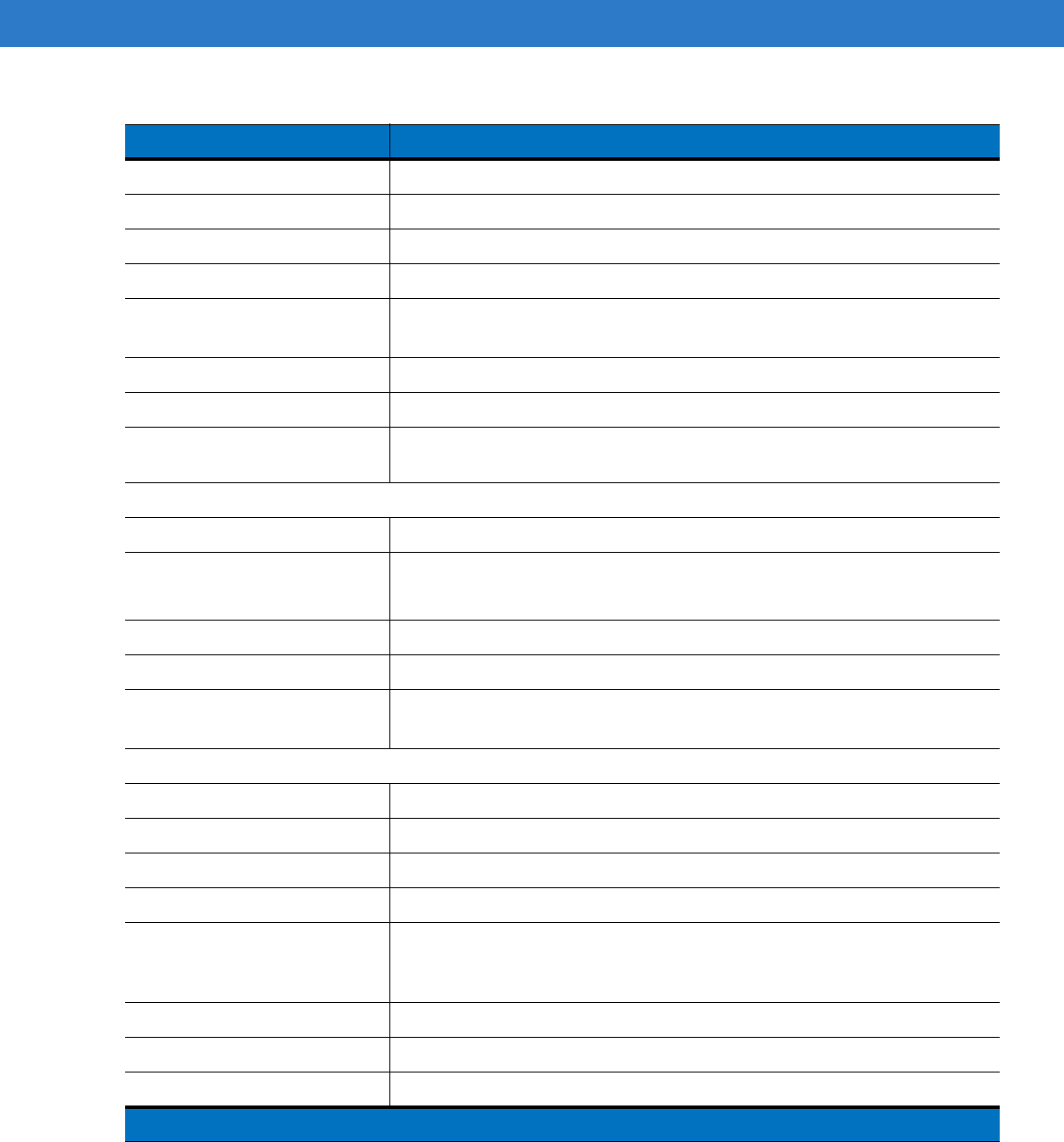
Table 8-1
Troubleshooting the MC75A
Problem Cause Solution
MC75A does not turn
on. Battery not charged. Charge or replace the battery.
Battery not installed
properly. Install the battery properly. See
Installing the Main Battery on page
1-4
.
System crash. Perform a warm boot. If the MC75A still does not turn on, perform a
cold boot. See
Resetting the MC75A on page 2-17
.
Rechargeable battery
did not charge. Battery failed. Replace battery. If the MC75A still does not operate, perform a
warm boot, then a cold boot. See
Resetting the MC75A on page
2-17
.
MC75A removed
from cradle while
battery was
charging.
Insert MC75A in cradle and allow to charge.
Extreme battery
temperature. Battery does not charge if ambient temperature is below 0°C (32°F)
or above 40°C (104°F).
Cannot see characters
on display. MC75A not
powered on. Press the red
Power
button.
DRAFT
8 - 6 MC75A Enterprise Digital Assistant User Guide
During data
communication, no
data transmitted, or
transmitted data was
incomplete.
MC75A removed
from cradle or
disconnected from
host computer
during
communication.
Replace the MC75A in the cradle, or reattach the communication
cable and re-transmit.
Incorrect cable
configuration. See the system administrator.
Communication
software was
incorrectly installed
or configured.
Perform setup. Refer to the MC75A Enterprise Digital Assistant
Integrator Guide for details.
No sound. Volume setting is
low or turned off. Adjust the volume. See
Adjusting Volume on page 2-12
.
MC75A shuts off. MC75A is inactive. The MC75A turns off after a period of inactivity. If the MC75A is
running on battery power, set this period from 1 to 5 minutes, in
one-minute intervals. If the MC75A is running on external power, set
this period to 1, 2, 5, 10, 15, or 30 minutes.
Check the
Power
window by selecting
Start
>
Settings
>
Power
icon. Select the
Advanced
tab and change the setting for a longer
delay before the automatic shutoff feature activates.
Battery is depleted. Recharge or replace the battery.
Battery is not
inserted properly. Insert the battery properly. See
Installing the Main Battery on page
1-4
.
Tapping the window
buttons or icons does
not activate the
corresponding feature.
Screen is not
calibrated correctly. Re-calibrate the screen. See
Calibrating the Screen on page 1-7
.
The system is not
responding. Warm boot the system. See
Resetting the MC75A on page 2-17
.
A message appears
stating that the MC75A
memory is full.
Too many files
stored on the
MC75A.
Delete unused memos and records. If necessary, save these
records on the host computer (or use an SD card for additional
memory).
Too many
applications
installed on the
MC75A.
Remove user-installed applications on the MC75A to recover
memory. Select
Start
>
Settings
>
System
and tap the
Remove
Programs
icon. Select the unused program and tap
Remove.
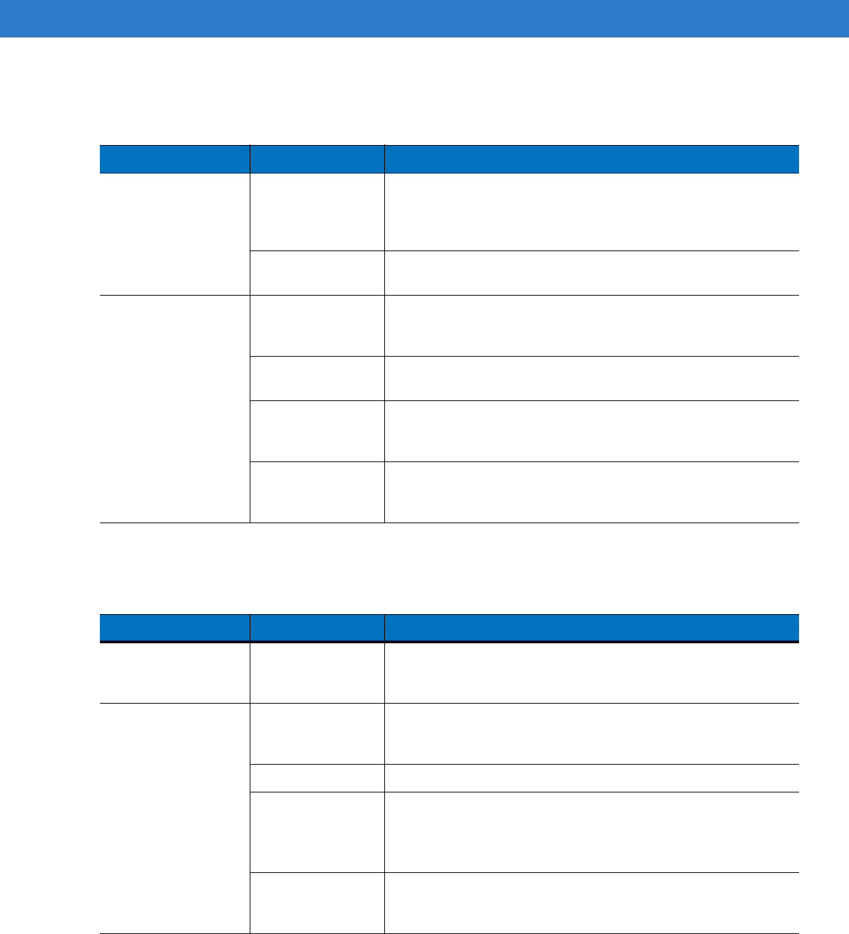
Table 8-1
Troubleshooting the MC75A (Continued)
Problem Cause Solution
DRAFT
Maintenance & Troubleshooting 8 - 7
Bluetooth Connection
MC75A keeps
powering down to
protect memory
contents.
The MC75A’s
battery is low. Recharge or replace the battery.
The internal
Bluetooth radio is
powered on for a
long time.
Because this mode requires battery power, power it off when not
needed.
The MC75A does not
accept data capture
input.
Scanning
application is not
loaded.
Load a scanning application on the MC75A. See the system
administrator.
Unreadable bar
code. Ensure the symbol is not defaced.
Distance between
exit window and bar
code is incorrect.
Place the MC75A within proper scanning range.
MC75A is not
programmed for the
bar code.
Program the MC75A to accept the type of bar code being scanned.
MC75A is not
programmed to
generate a beep.
If the MC75A does not beep on a good decode, set the application
to generate a beep on good decode.
Battery is low. If the scanner stops emitting a laser beam upon a trigger press,
check the battery level. When the battery is low, the scanner shuts
off before the MC75A low battery condition notification. Note: If the
scanner is still not reading symbols, contact the distributor or
Motorola.
Table 8-1
Troubleshooting the MC75A (Continued)
Problem Cause Solution
Table 8-2
Troubleshooting Bluetooth Connection
Problem Cause Solution
MC75A cannot find
any Bluetooth devices
nearby.
Too far from other
Bluetooth devices. Move closer to the other Bluetooth device(s), within a range of 10
meters.
The Bluetooth
device(s) nearby are
not turned on.
Turn on the Bluetooth device(s).
The Bluetooth
device(s) are not in
discoverable mode.
Set the Bluetooth device(s) to discoverable mode. If needed, refer to
the device’s user documentation for help.
DRAFT
8 - 8 MC75A Enterprise Digital Assistant User Guide
Single Slot USB/Serial Cradle
When trying to
connect a Bluetooth
phone and MC75A,
the phone thinks a
previously paired
MC75A is used.
The phone
remembers the
name and address
of the MC75A it last
paired with via the
Bluetooth radio.
Manually delete the pairing device and name from the phone. Refer
to the phone’s user documentation for instructions.
There is a delay in the
Bluetooth stack
re-initializing during a
resume from
suspend.
This is normal
behavior. No solution required.
The Bluetooth
connection drops. The MC75A
suspends and the
Bluetooth radio
power turns off.
When the MC75A suspends the Bluetooth connection is dropped.
Re-connect the Bluetooth connection when the MC75A returns from
suspend mode.
Table 8-2
Troubleshooting Bluetooth Connection (Continued)
Problem Cause Solution
Table 8-3
Troubleshooting the Single Slot USB/Serial Cradle
Symptom Possible Cause Action
LEDs do not light
when MC75A or spare
battery is inserted.
Cradle is not
receiving power. Ensure the power cable is connected securely to both the cradle
and to AC power.
MC75A is not
seated firmly in the
cradle.
Remove and re-insert the MC75A into the cradle, ensuring it is
firmly seated.
Spare battery is not
seated firmly in the
cradle.
Remove and re-insert the spare battery into the charging slot,
ensuring it is firmly seated.
DRAFT
Maintenance & Troubleshooting 8 - 9
MC75A battery is not
charging. MC75A was
removed from
cradle or cradle was
unplugged from AC
power too soon.
Ensure cradle is receiving power. Ensure MC75A is seated
correctly. Confirm main battery is charging under
Start
>
Settings
>
Power
.
Battery is faulty. Verify that other batteries charge properly. If so, replace the faulty
battery.
The MC75A is not
fully seated in the
cradle.
Remove and re-insert the MC75A into the cradle, ensuring it is
firmly seated.
Ambient
temperature of the
cradle is too warm.
Move the cradle to an area where the ambient temperature is
between 0°C (32°F) and 35°C (95°F).
Extreme battery
temperature. Battery does not charge if ambient temperature is below 0°C (32°F)
or above 40°C (104°F).
Spare battery is not
charging. Spare battery
inserted incorrectly. Re-insert the spare battery so the charging contacts on the battery
align with the contacts on the cradle.
Spare battery is
faulty. Verify that other batteries charge properly. If so, replace the faulty
battery.
Ambient
temperature of the
cradle is too warm.
Move the cradle to an area where the ambient temperature is
between 0°C (32°F) and 35°C (95°F).
During data
communication, no
data transmits, or
transmitted data was
incomplete.
MC75A removed
from cradle during
communications.
Replace MC75A in cradle and retransmit.
Incorrect cable
configuration. See the system administrator.
Communication
software is not
installed or
configured properly.
Perform setup as described in the MC75A Enterprise Digital
Assistant Integrator Guide.
Table 8-3
Troubleshooting the Single Slot USB/Serial Cradle (Continued)
Symptom Possible Cause Action
DRAFT
8 - 10 MC75A Enterprise Digital Assistant User Guide
Four Slot Ethernet Cradle
Vehicle Cradle
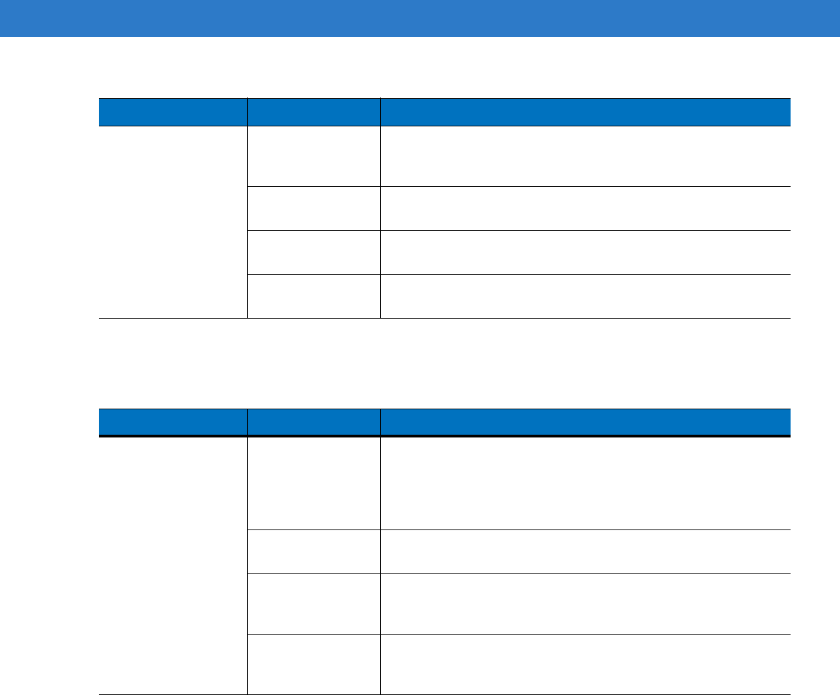
Table 8-4
Troubleshooting the Four Slot Ethernet Cradle
Symptom Cause Solution
During
communication, no
data transmits, or
transmitted data was
incomplete.
MC75A was
removed from
cradle during
communications.
Replace MC75A in cradle and retransmit.
MC75A has no
active connection. An icon is visible in the status bar if a connection is currently active.
Battery is not
charging. MC75A removed
from the cradle too
soon.
Replace the MC75A in the cradle.Tap
Start
>
Settings
>
Power
to
view battery status.
Battery is faulty. Verify that other batteries charge properly. If so, replace the faulty
battery.
MC75A is not
inserted correctly in
the cradle.
Remove the MC75A and reinsert it correctly. Verify charging is
active. Tap
Start
>
Settings
>
Power
to view battery status.
Ambient
temperature of the
cradle is too warm.
Move the cradle to an area where the ambient temperature is
between 0°C (32°F) and 35°C (95°F).
Table 8-5
Troubleshooting the Vehicle Cradle
Symptom Possible Cause Action
MC75A battery
charging LED does not
light up.
Cradle is not
receiving power. Ensure the power input cable is securely connected to the cradle’s
power port.
MC75A battery is not
recharging. MC75A was
removed from the
cradle too soon.
Replace the MC75A in the cradle.
Battery is faulty. Replace the battery.
MC75A is not
placed correctly in
the cradle.
Remove the MC75A from the cradle, and re-insert correctly. If the
battery still does not charge, contact customer support.
The MC75A battery charging LED slowly blinks amber when the
MC75A is correctly inserted and charging.
Ambient
temperature of the
cradle is too warm.
Move the cradle to an area where the ambient temperature is
between 0°C (32°F) and 35°C (95°F).
DRAFT
Maintenance & Troubleshooting 8 - 11
Four Slot Battery Charger
r
No data transmitted, or
transmitted data was
incomplete.
MC75A removed
from cradle during
communication.
Replace MC75A in cradle and retransmit.
No null modem
cable was used. Some external devices require a null modem cable. Retransmit
using a null modem cable.
Incorrect cable
configuration. See the system administrator.
Cable missing or
disconnected. Re-connect cable.
Table 8-5
Troubleshooting the Vehicle Cradle
Symptom Possible Cause Action
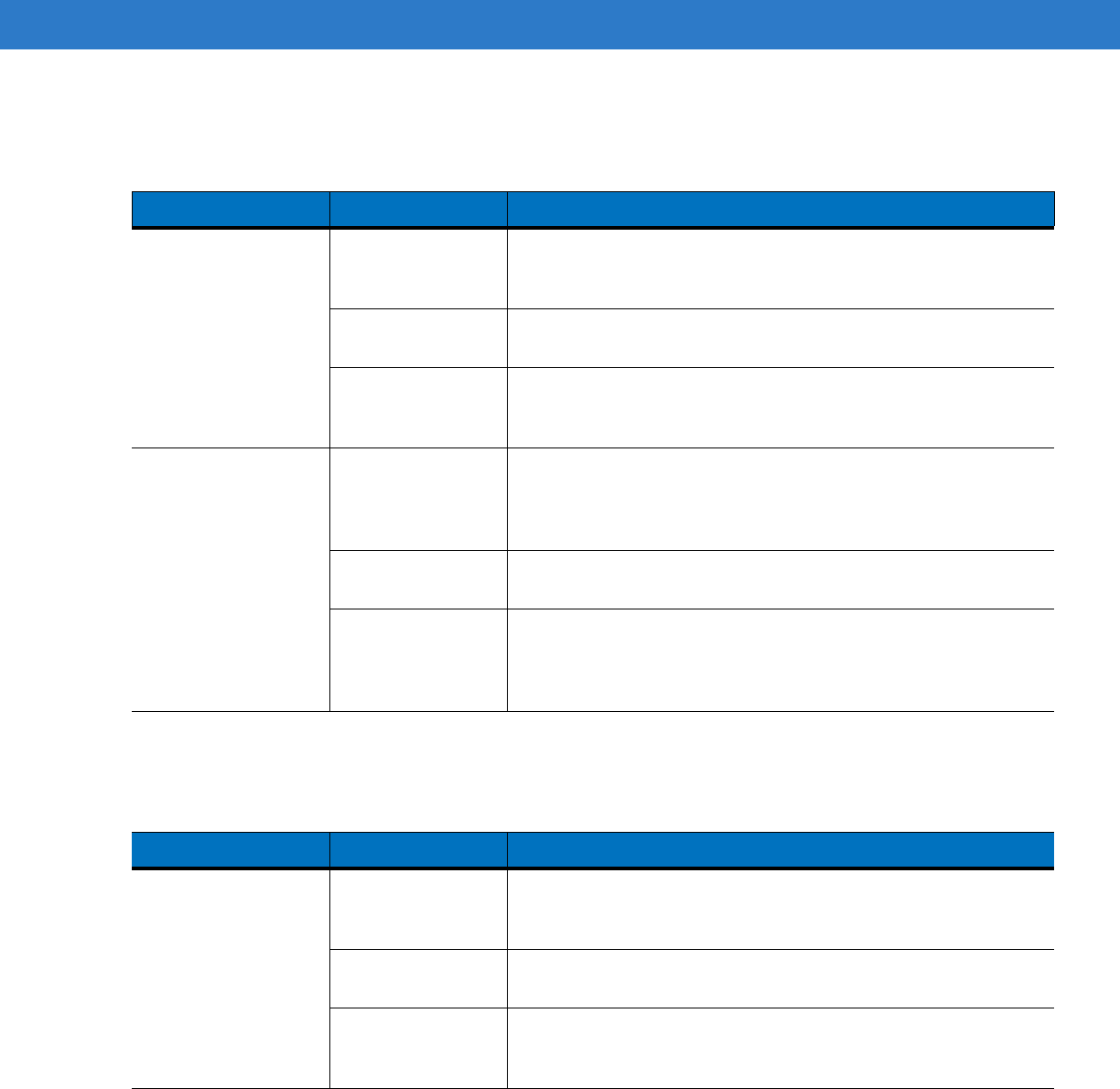
Table 8-6
Troubleshooting The Four Slot Battery Charger
Symptom Possible Cause Action
Battery not charging. Battery was
removed from the
charger or charger
was unplugged from
AC power too soon.
Re-insert the battery in the charger or re-connect the charger’s
power supply.
Battery is faulty. Verify that other batteries charge properly. If so, replace the faulty
battery.
Battery contacts not
connected to
charger.
Verify that the battery is seated in the battery well correctly with the
contacts facing down.
Ambient
temperature of the
cradle is too warm.
Move the cradle to an area where the ambient temperature is
between 0°C (32°F) and 35°C (95°F).
DRAFT
8 - 12 MC75A Enterprise Digital Assistant User Guide
Cables
Magnetic Stripe Reader
Table 8-7
Troubleshooting the Cables
Symptom Possible Cause Action
MC75A battery is not
charging. MC75A was
disconnected from
AC power too soon.
Connect the power cable correctly. Confirm main battery is charging
under
Start
>
Settings
>
Power
.
Battery is faulty. Verify that other batteries charge properly. If so, replace the faulty
battery.
The MC75A is not
fully attached to
power.
Detach and re-attach the power cable to the MC75A, ensuring it is
firmly connected.
During data
communication, no
data transmits, or
transmitted data was
incomplete.
Cable was
disconnected from
MC75A during
communications.
Re-attach the cable and retransmit.
Incorrect cable
configuration. See the system administrator.
Communication
software is not
installed or
configured properly.
Perform setup as described in the MC75A Integrator Guide.
Table 8-8
Troubleshooting the Magnetic Stripe Reader
Symptom Possible Cause Action
MSR cannot read
card. MSR removed from
MC75A during card
swipe.
Reattach MSR to MC75A and reswipe the card.
Faulty magnetic
stripe on card. See the system administrator.
MSR application is
not installed or
configured properly.
Ensure the MSR application is installed on the MC75A.
Ensure the MSR application is configured correctly.
DRAFT
Maintenance & Troubleshooting 8 - 13
MC75A battery is not
charging. MC75A was
removed from MSR
or MSR was
unplugged from AC
power too soon.
Ensure MSR is receiving power. Ensure MC75A is attached
correctly. Confirm main battery is charging under
Start
>
Settings
>
Power
.
Battery is faulty. Verify that other batteries charge properly. If so, replace the faulty
battery.
The MC75A is not
fully attached to the
MSR.
Detach and re-attach the MSR to the MC75A, ensuring it is firmly
connected.
During data
communication, no
data transmits, or
transmitted data was
incomplete.
MC75A detached
from MSR during
communications.
Reattach MC75A to MSR and retransmit.
Incorrect cable
configuration. See the system administrator.
Communication
software is not
installed or
configured properly.
Perform setup as described in the MC75A Integrator Guide.
Table 8-8
Troubleshooting the Magnetic Stripe Reader (Continued)
Symptom Possible Cause Action
DRAFT

8 - 14 MC75A Enterprise Digital Assistant User Guide
DRAFT
Appendix A Technical Specifications
MC75A Technical Specifications
The following tables summarize the MC75A’s intended operating environment and technical hardware
specifications.
MC75A
Table A-1
MC75A Technical Specifications
Item Description
Physical Characteristics
Dimensions MC75A0:
Length: 15.2 cm (6.00 in.)
Width: 8.4 cm (3.30 in.)
Depth: 4.4 cm (1.70 in.)
MC75A6/8:
Length: 17.9 cm (7.05 in.)
Width: 8.4 cm (3.30 in.)
Depth: 4.4 cm (1.70 in.)
Weight MC75A0:
364 g (12.84 oz) - with 1950 mAh battery
398g (14.04 oz) - with 3600 mAh battery
MC75A6/8:
389 g (13.72 oz) - with 1950 mAh battery
423 g (14.92 oz) - with 3600 mAh battery
Display Transflective color 3.5” VGA with backlight, TFT-LCD, 65K colors,
480 W x 640 L (VGA size)
Touch Panel Glass analog resistive touch
Note 1: Total output power can be either USB or serial or a combination of both that cannot exceed 200 mA.
DRAFT
A - 2 MC75A Enterprise Digital Assistant User Guide
Backlight LED backlight
Main Battery Rechargeable Lithium Ion 3.7V, 1950, 3800 or 4800 mAh Smart Battery
Backup Battery NiMH battery (rechargeable) 15 mAh 2.4V (not user-accessible)
Expansion Slot User accessible microSD slot (with secure cover).
Network Connections Ethernet (via cradle)
Full-speed USB, host or client, Bluetooth
Notification Vibrator and LED
Keypad Options Numeric, DSD, QWERTY, AZERTY and QWERTZ
Audio Speaker, receiver, microphone, headset jack, software support for full duplex
record and playback (stereo)
Performance Characteristics
CPU Marvell PXA320 processor at 806 MHz
Operating System MC75A0: Microsoft
®
Windows Mobile™ 6.5 Classic
MC75A6/8: Microsoft
®
Windows Mobile™ 6.5 Professional
Memory 256MB RAM/1GB FLASH
Interface/Communications RS-232, USB 1.1, IrDA
Output Power (Note 1) USB: 5 VDC @ 200 mA max.
Serial: 5 VDC @ 200 mA max.
User Environment
Operating Temperature -10°C to 50°C (14°F to 122°F)
Storage Temperature -40°C to 60°C (-40°F to 140°F) - without battery
Charging Temperature 32°F to 104°F / 0° C to 40° C
Humidity 95% non-condensing
Drop Specification 1.5 m (5 ft.) drop to concrete, at ambient temperature 23°C (73°F).
1.2 m (4 ft.) drop to concrete, over operating temperature range. Meets and
Exceeds MIL-STD 810G.
Tumble 1,000 0.5 m (1.6 ft.) tumbles (2,000 drops)
Electrostatic Discharge (ESD) +/-15kVdc air discharge, +/-8kVdc direct discharge, +/-8kVdc indirect discharge
Sealing IP54
Table A-1
MC75A Technical Specifications (Continued)
Item Description
Note 1: Total output power can be either USB or serial or a combination of both that cannot exceed 200 mA.
DRAFT