Symbol Technologies MC75A6 EDA (Enterprise Digital Assistant) User Manual MC75A User Guide
Symbol Technologies Inc EDA (Enterprise Digital Assistant) MC75A User Guide
UserManual.wiki
>
Symbol Technologies
>
MC75A6 User Manual
>
user manual 5
Contents
1.
User manual 1
2.
User manual 2
3.
User manual 3
4.
User manual 4
5.
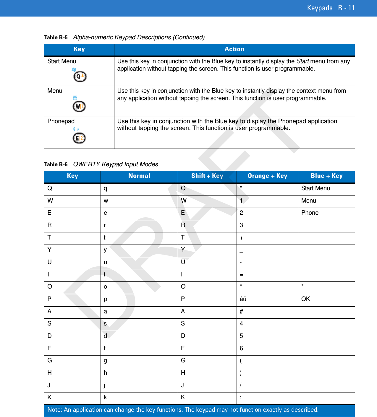
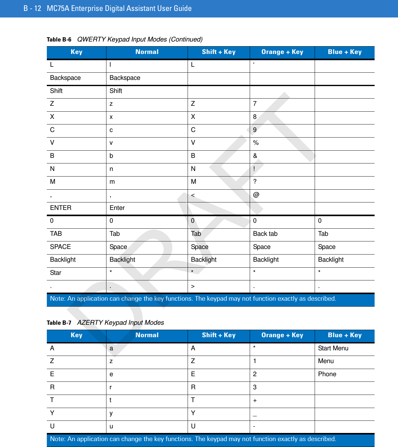
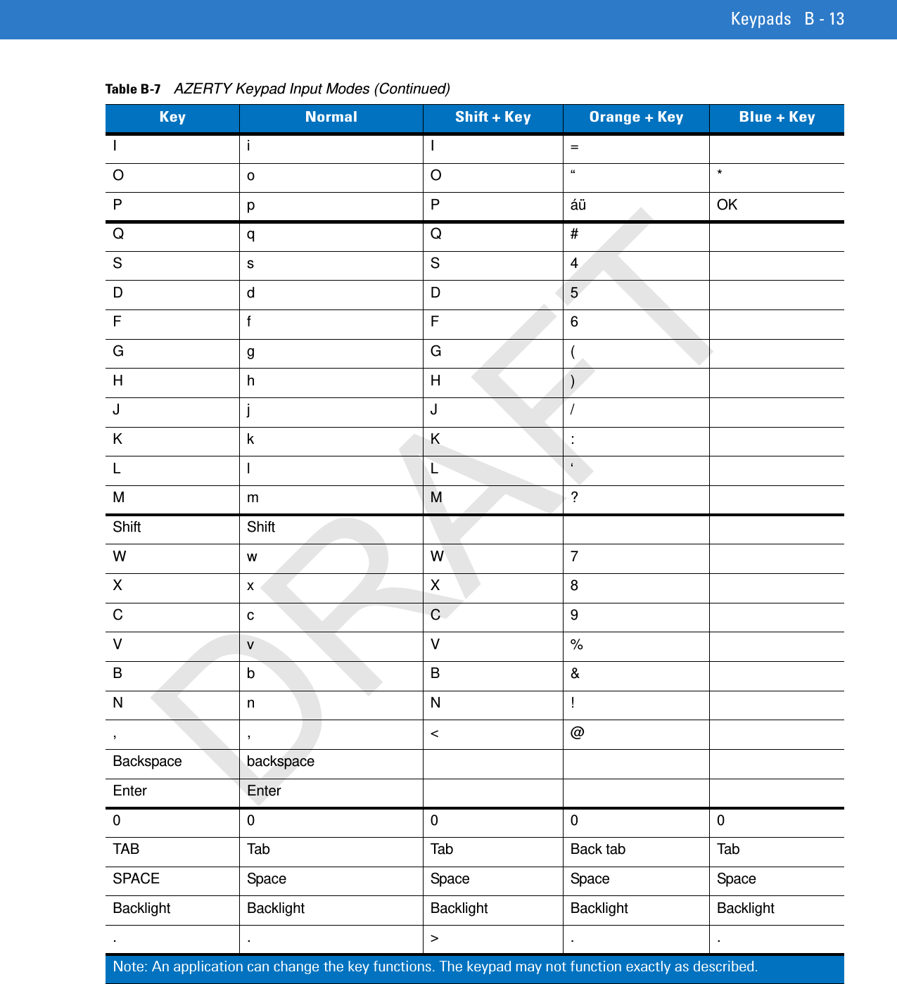
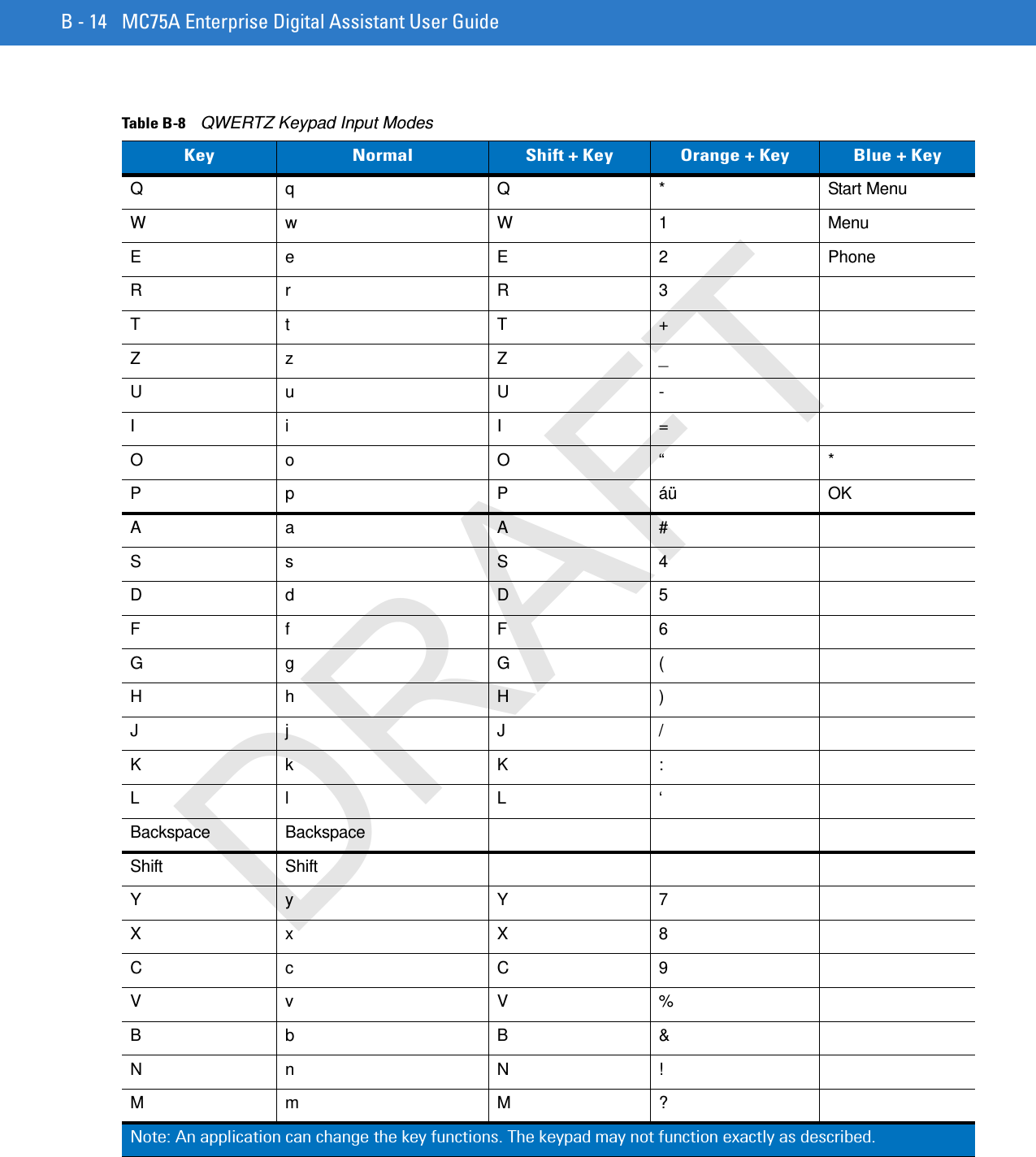
User manual 5
6.
User manual 6
7.
user manual 1
8.
user manual 2
9.
user manual 3
10.
user manual 4
11.
user manual 5
12.
user manual 6
user manual 5
Navigation menu
Upload a User Manual
Namespaces
Wiki Guide
HTML
PDF
Info
Views
User Manual
Discussion / Help
Navigation