Symbol Technologies MR100A Spread Spectrum Transmitter User Manual AR400
Symbol Technologies Inc Spread Spectrum Transmitter AR400
UserManual.wiki
>
Symbol Technologies
>
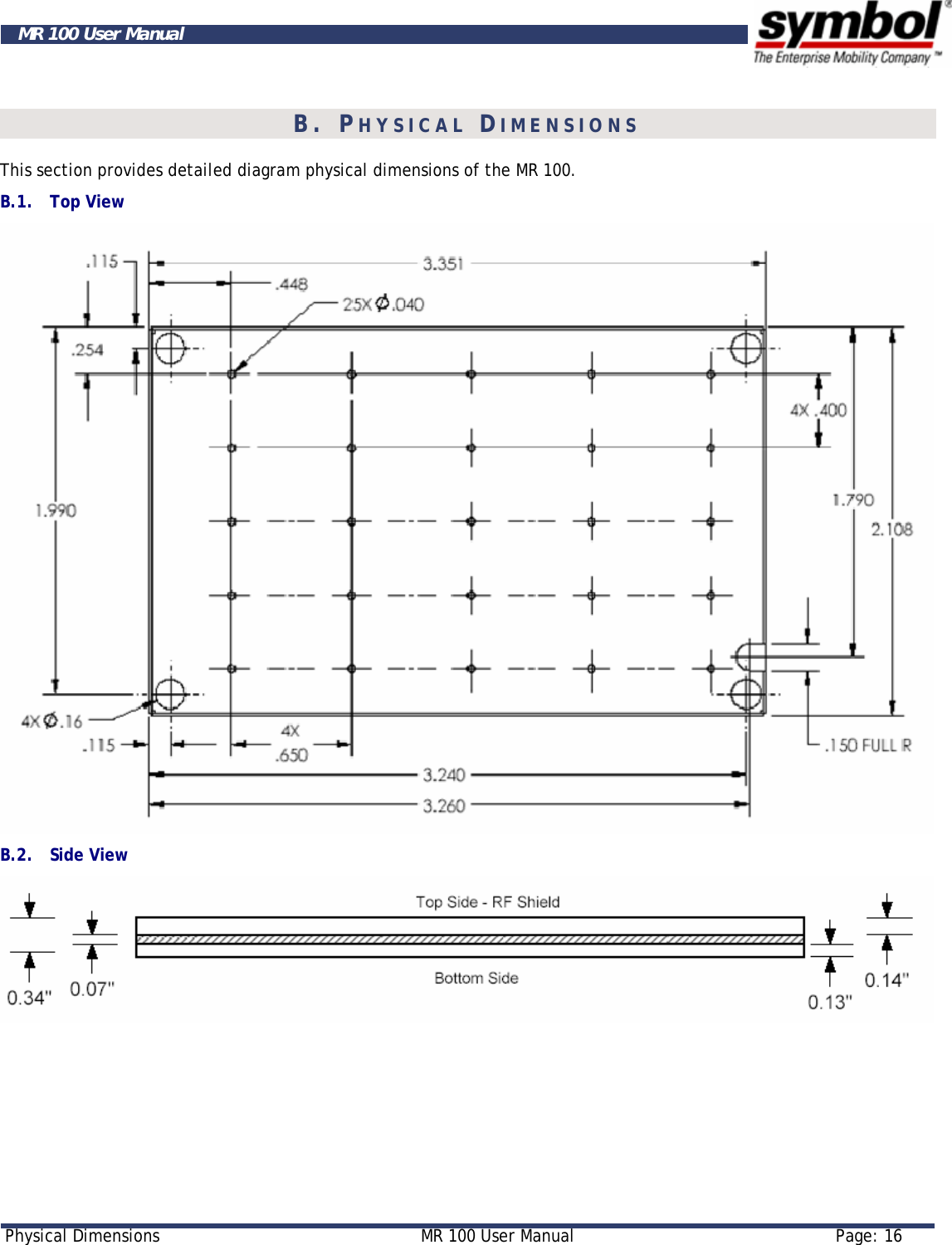
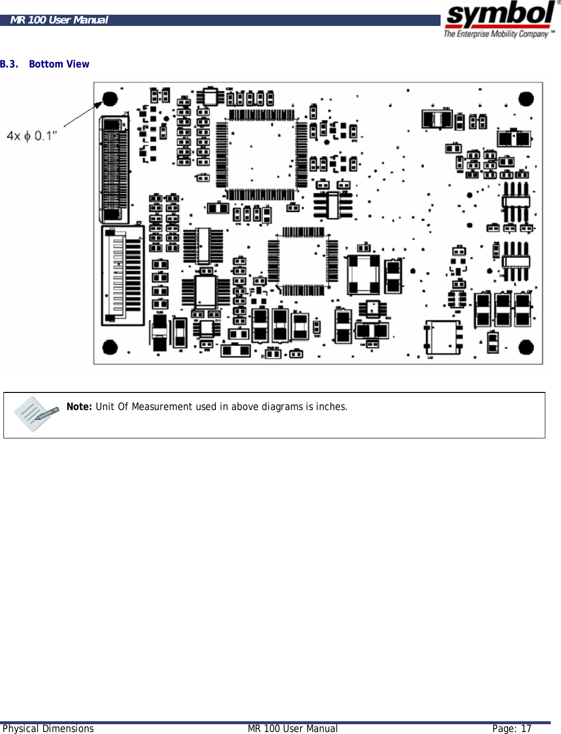
MR100A User Manual
Manual
Navigation menu
Upload a User Manual
Namespaces
Wiki Guide
HTML
PDF
Info
Views
User Manual
Discussion / Help
Navigation