Symbol Technologies MR100A Spread Spectrum Transmitter User Manual AR400
Symbol Technologies Inc Spread Spectrum Transmitter AR400
Manual
MR 100 User Manual
MR 100 User Manual
MR 100
User Manual
Document Version: Version 1.2
Document Category: Product Manuals
Symbol Technologies Inc.,
7361 Calhoun Place,
Suite 250
Rockville, MD 20855
Phone: (301) 610-6100
Fax: (301) 610-6101
http://www.symbol.com

MR 100 User Manual
MR 100 User Manual
Notices
Copyright © 2004 Symbol, Inc. All rights reserved.
This document is protected by copyright with all rights reserved. No part of the document may be reproduced or
transmitted by any means or in any form without prior consent in writing from Symbol, Inc.
Trademarks
Symbol is a registered trademark of Symbol, Inc. All other product names or logos mentioned herein are used for
identification purposes only, and are the trademarks of their respective owners.
Statement of Rights
Symbol products incorporate technology that is protected by U.S. patent and other intellectual property (IP) rights
owned by Symbol, Inc, and other rights owners. Use of these products constitutes your legal agreement to honor
Symbol’ IP rights as protected by applicable laws. Reverse engineering, de-compiling, or disassembly of Symbol
products is strictly prohibited. Violators will be prosecuted.
Disclaimer
While Symbol has committed its best efforts to providing accurate information in this document, we assume no
responsibility for any inaccuracies that may be contained herein, and we reserve the right to make changes to this
document without notice.

Table of Contents MR 100 User Manual Page ii
MR 100 User Manual
Table of Contents
Chapter 1. Introduction .................................................................................................................. 4
1.1. Scope............................................................................................................................... 4
1.1.1. Target Audience............................................................................................................... 4
1.1.2. Assumptions.................................................................................................................... 4
1.2. Document Organization......................................................................................................... 4
1.3. Document Conventions.......................................................................................................... 5
1.4. Abbreviations..................................................................................................................... 5
1.5. Additional Documentation Available.......................................................................................... 5
Chapter 2. An introduction to MR 100................................................................................................. 6
2.1. MR 100 Features.................................................................................................................. 6
2.1.1. Designed for Embedded Applications...................................................................................... 6
2.1.2. Robustness ..................................................................................................................... 6
2.1.3. Performance ................................................................................................................... 6
2.1.4. Support for Industry Standards ............................................................................................. 6
2.2. What’s shipped................................................................................................................... 6
2.3. Product Pictures ................................................................................................................. 7
2.4. Basic Connections................................................................................................................ 7
Chapter 3. Byte Stream Protocol with MR 100 ...................................................................................... 8
3.1. Byte Stream and MR 100 ........................................................................................................ 8
3.2. Generalized Request and Response Packets described .................................................................... 8
Chapter 4. Byte Stream Command List...............................................................................................10
4.1. Read Full Field Command (22hex).............................................................................................10
4.2. Set Parameter Block Command (23hex) ......................................................................................10
4.3. Get Parameter Block Command (24hex)......................................................................................10
4.4. Set Node Address Command (12hex) ..........................................................................................10
4.5. Get Reader Status Command (14hex) .........................................................................................10
4.6. Set Suspend Mode Command (18hex) .........................................................................................10
4.7. Get Node Address Command (19hex) .........................................................................................10
4.8. Set Baud Rate Command (1Dhex)..............................................................................................10
4.9. Read With Payload Command (31hex) ........................................................................................11
4.10. Kill Specific (32 hex).............................................................................................................11
4.11. Write Tag (33hex) ................................................................................................................11

Table of Contents MR 100 User Manual Page iii
MR 100 User Manual
A. Hardware and Technical Specifications ..........................................................................................14
A.1. Physical Dimensions ............................................................................................................14
A.2. Power .............................................................................................................................14
A.3. Environmental ...................................................................................................................14
A.4. Connectivity .....................................................................................................................14
A.5. Interface Pin Outs...............................................................................................................15
A.6. Operational Features...........................................................................................................15
A.7. Compliance ......................................................................................................................15
B. Physical Dimensions...................................................................................................................16
B.1. Top View .........................................................................................................................16
B.2. Side View.........................................................................................................................16
B.3. Bottom View .....................................................................................................................17
C. Compliance & Regulatory Information ............................................................................................18
Safety Information...................................................................................................................18

Introduction MR 100 User Manual Page: 4
MR 100 User Manual
Chapter 1.
INTRODUCTION
1.1. Scope
The Symbol MR100 Reader User Manual provides the following information pertaining to Symbol MR100 Receiver
Module:
Hardware Specifications and details.
Supported API calls.
1.1.1. Target Audience
This guide is targeted for developers who will be writing code that interfaces with MR 100 reader using the Byte
Stream Protocol.
1.1.2. Assumptions
This manual assumes that besides being familiar with windows based environment you also have a basic idea of the
following:
Basic RFID concepts and terminologies.
Proficieny with atleast one programming language which is capable of accessing the MR 100 API.
Basic networking terms e.g. IP Address, DHCP, Protocol etc.
The manual does not contain detailed information and material on the above-mentioned topics.
1.2. Document Organization
This document has been organized as described in the table below:
Chapter No. Chapter Title Information Contained in the Chapter
1 Introduction An overview of what the Document contains, who the
targeted audience is and how the document is organized.
2 An introduction to MR 100 A brief description of the Product and its features.
3 Byte Stream Protocol with MR
100 A Basic introduction to byte stream protocol and how it
can be used to interface with the MR 100 Reader.
4 Supported APIs Specifications of API supported by Symbol MR 100
readers.
Appendix A Hardware Specifications Hardware specifications and details of reader interfaces.
Appendix B Physical Dimensions Physical Dimensions of the MR 100
Introduction MR 100 User Manual Page: 5
MR 100 User Manual
1.3. Document Conventions
The following Conventions have been used in this Guide:
Document Convection Version
Bulleted List Provides Grouped Action and non procedural steps
1. Numbered List Procedural steps for performing an action.
A Note / Focus point that the reader might be interested in knowing.
A Warning Note.
A Caution Note.
1.4. Abbreviations
The Following acronyms and abbreviations have been used in the System Manual:
Acronym / Abbreviation Expansion / Explanation
RFID Radio Frequency Identification
EPC Electronic Product Code - industry-driven standard of identification scheme for RFID
Tags.
Read Point An individually addressable antenna
Read Point Class Configuration Parameters that may be applied to one or more read points
1.5. Additional Documentation Available
The following additional documentation may be useful to the users of this manual:
Matrics API Programmer’s Manual (PN: 110009-001).
MR 100 Data Sheet.
http://www.symbol.com (for FAQ and Product Updates)

An introduction to MR 100 MR 100 User Manual Page: 6
MR 100 User Manual
Chapter 2.
AN INTRODUCTION TO MR 100
The Symbol RF Receiver Module or MR 100 is a single port, lightweight reader designed for easy integration with RFID
printers, handhelds and applicators1. This chapter describes some of the important features of MR 100.
2.1. MR 100 Features
2.1.1. Designed for Embedded Applications
The Symbol MR 100 offers a simplified design and better utilization of board space, which results in a small and
lightweight device that can be used very effectively in embedded systems.
2.1.2. Robustness
The MR 100 Reader is highly robust and can be used in environment with extreme temperatures and humidity. It is
capable of functioning from temperatures ranging from –20DC to +60DC and 5% to 95% humidity.
2.1.3. Performance
The MR 100 uses a Symbol patented interrogation protocol, which makes it capable of Read rates of up to 200 tags per
second. The same protocol also enabled it to work in noisy environments.
The MR 100 has a read range of up to of 10+ feet, and a write range of up to 4+ feet. The range however, depends on
factors like Antenna Gain, interference and traffic.
2.1.4. Support for Industry Standards
The MR 100 provides all RF and control functions that are required for powering and communicating with industry
standard UHF passive tags. It has capabilities of interacting with both Class 0(Read Only) and Class 0 (Read Write) tags
2.2. What’s shipped
The customer has multiple options to choose from while purchasing the MR100.
Host Interface Æ the JST 14-Pin Connector can be used to connect the MR 100 to devices. the customer can
choose between RS 232 (serial) or TTL interface depending on the device to which the MR 100 will be
connected to.
Antenna Port Æ depending on, what the MR 100 needs to be deployed for, the customer has an option of
purchasing the single antenna port version (which uses the same antenna for both transmissing and receiving)
or dual port (which allows the use of separate antenna for transmitting and a separate antenna for receiving).
1 With appropriate regulatory certifications
An introduction to MR 100 MR 100 User Manual Page: 7
MR 100 User Manual
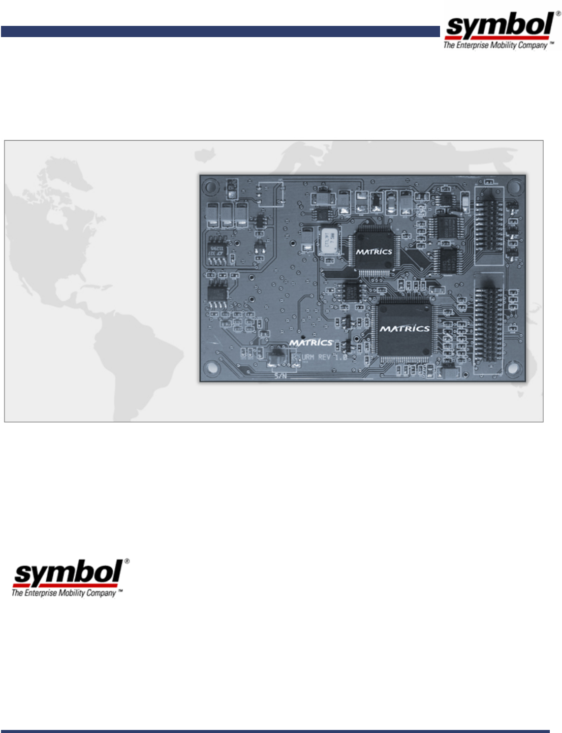
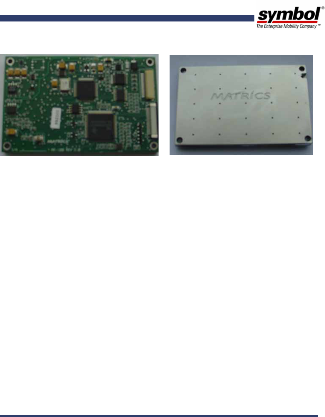
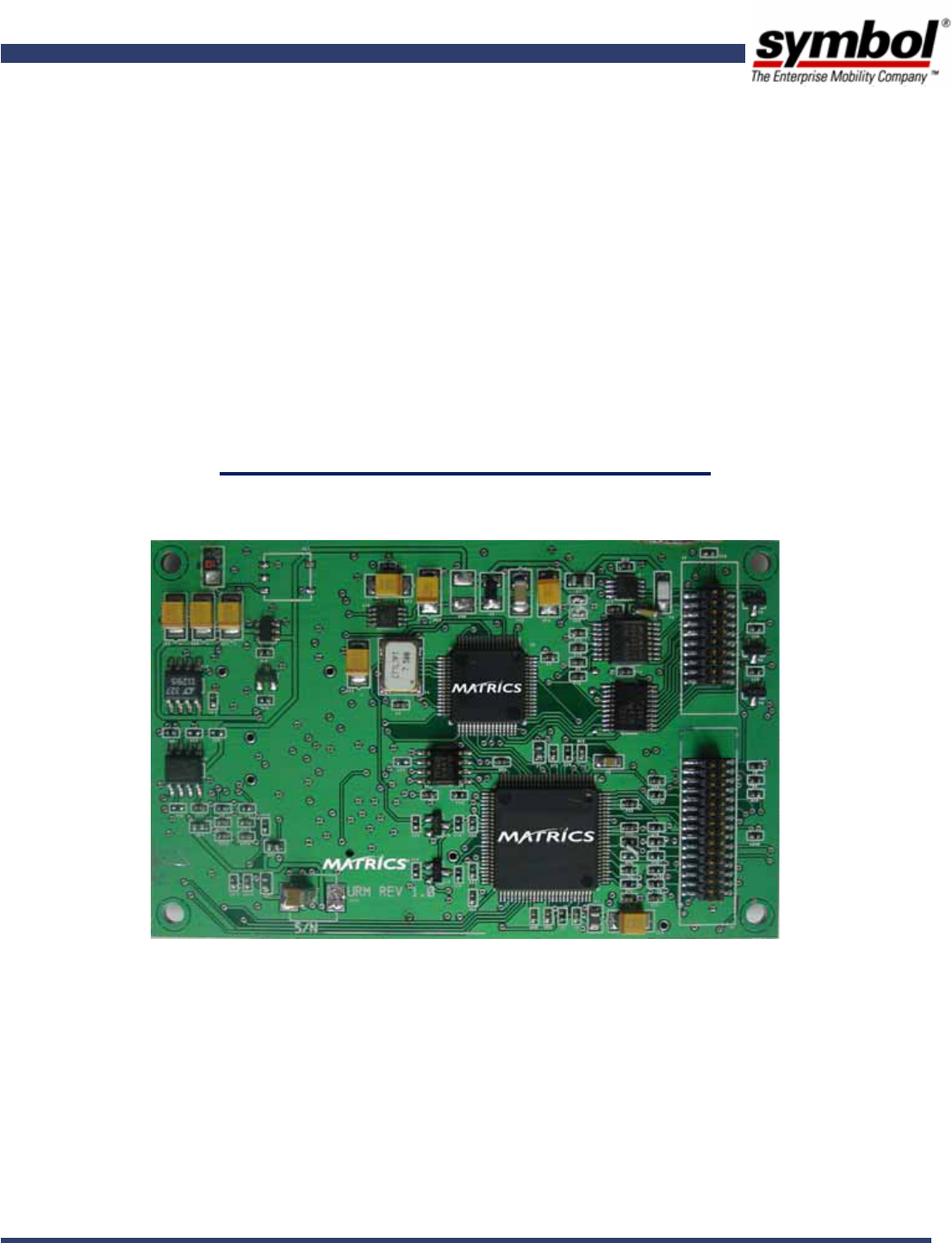
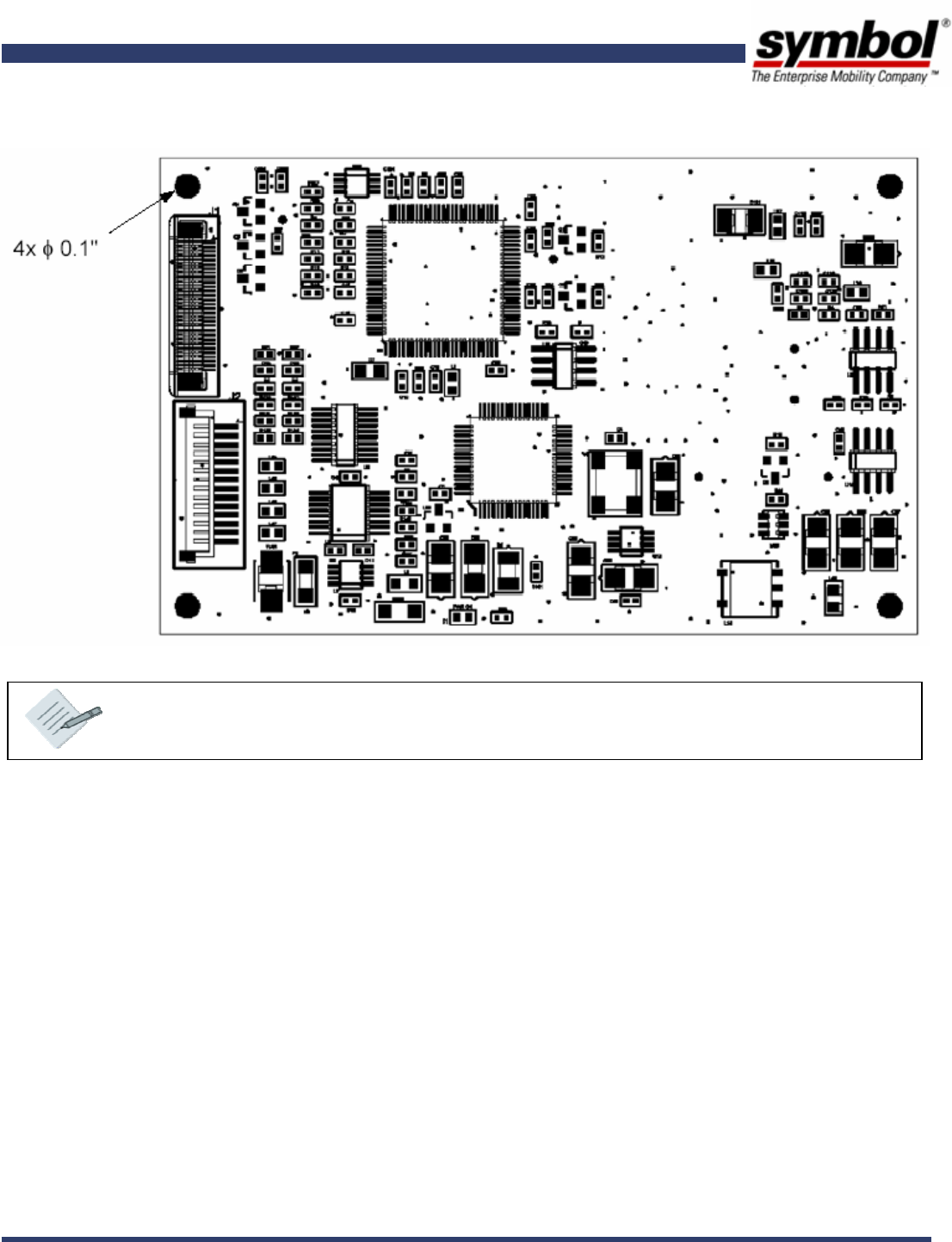
2.3. Product Pictures
Board View Top View
2.4. Basic Connections
Connecting the MR 100 to your system is fairly easy and includes a simple two step process:
Connect the MR 100 to the device you plan to use with the reader using the JST 14-Pin Connector. Depending
on the device you wish to connect to you should select between the RS 232 / TTL interfaces before ordering
your MR 100.
Connect the MR 100 antenna port to your antenna: If you are using a MR 100 with a dual antenna port
connect one to a transmitting and 1 to a receiving antenna. If you are using a MR 100 with a single antenna
port connect the antenna port to the antenna – in this case the single antenna acts as a transmitting and
receiving antenna. Your choice of antenna will vary depending upon the read write distance that you want with
your MR-100. e.g. For a typical read range of 10’ and a write range of 4’ an antenna of 6dBi gain must be
selected.

Byte Stream Protocol with MR 100 MR 100 User Manual Page: 8
MR 100 User Manual
Chapter 3.
BYTE STREAM PROTOCOL WITH MR 100
This chapter gives a brief introduction to Byte Stream Protocol and how it can be used to communicate with the MR
100 reader. If you are looking for more details of Byte Stream Protocol and how it can be used with other Symbol
Readers refer to Matrics API Programmers Manual.
3.1. Byte Stream and MR 100
Byte stream protocol can be used to send data to the host using a 2 wire serial link (RS-232) or TTL as factory option at
the following Baud Rates:
19200
38400
57600
115200
3.2. Generalized Request and Response Packets described
The byte stream packet follows generalized packet format for request and response packet. This section describes the
packet format which most request and response examples in this document will use. In practical implementation, most
of the times, these packets are arrays of bytes where elements are arranged as per specified format.
A general request packet that is being sent to MR 100 over host interface must be formatted as follows:
Field Number of Bytes
(Size) Value Description
SOF 1 0x01 Start Of Frame
Node Address 1 0~0x1F i.e. 0 to 31. Node address that had been set on the reader
Packet Length 1 See Description Size of the packet that is being sent. This should not
include the size of SOF but should include the size of CRC.
Command 1 See Description Each Reader API Command corresponds to a number. This
number tells the reader which command to fire. Populate
this byte with the value of the command which you want
the reader to fire.
Data Variable See Description Depending upon the command you are executing you may
need to send different number of bytes formatted
differently. See the definition of the command you want
to execute for more details. A Typical Request data
packet can be 0 to 64 bytes.
CRC 2
(1 for LSB & 1 for
MSB)
Dependent Bitwise inversion of the 16-bit CCITT-CRC of the packet
excluding SOF, with the LSB (Least Significant Byte) first.

Byte Stream Protocol with MR 100 MR 100 User Manual Page: 9
MR 100 User Manual
For every request sent to the reader there may be one / more response packets that the reader sends back to the host.
A Typical Response Packet has been described in the following table:
Field Number of Bytes
(Size) Value Description
SOF 1 0x01 Described in Request Packet description.
Node Address 1 0~0x1F Described in Request Packet description.
Packet Length 1 See Description Described in Request Packet description.
Command
Mirror 1 See Description Mirror of the original command in the response packet.
Status 1 See Description The result or status of a command execution. See Status
Field Description section for more details.
Data Variable See Description In a typical response packet the size of data field may
vary from 0 – to 250 bytes. The first byte of response data
usually contains the error code if error bit of status field
has been set. For more information on error bit see Status
Field Description section. For more information on error
codes see Error Codes Described section.
CRC 2
(1 for LSB & 1 for
MSB)
Dependent Bitwise inversion of the 16-bit CCITT-CRC of the packet
excluding SOF, with the LSB (Least Significant Byte) first.
For more information on the Byte Stream Protocol section of the Matrics API Programmers Manual.

Byte Stream Command List MR 100 User Manual Page: 10
MR 100 User Manual
Chapter 4.
BYTE STREAM COMMAND LIST
Below is a listing of all commands that are supported by the MR 100 reader. For more information of how to use each
command refer to the Matrics API Programmers Manual.
4.1. Read Full Field Command (22hex)
Read all RFID tags using one antenna port of the addressed reader. With the MR 100 you can use this command to read
tags using the first and only antenna port of the reader. Other antenna ports (2-4) should not be used while using the
command with the MR 100. For more information on this command refer to the Matrics API Programmers Manual.
4.2. Set Parameter Block Command (23hex)
Set parameters related to the first and only antenna port of the address MR 100 reader. For other readers this
command is capable of initializing more than one antenna simultaneously. However, for MR 100 only the first antenna
port must be initialized.
While using this command also ensure that you do not use combination features since MR 100 supports only one
antenna and does not support combination. For more information on this command refer to the Matrics API
Programmers Manual.
4.3. Get Parameter Block Command (24hex)
Get parameters for one specific antenna port. For the MR-100 this command should be used only by passing the logical
indicator of the first (only) antenna in the request packet. For more information on this command refer to the Matrics
API Programmers Manual.
4.4. Set Node Address Command (12hex)
For more information on this command refer to the Matrics API Programmers Manual.
4.5. Get Reader Status Command (14hex)
For more information on this command refer to the Matrics API Programmers Manual.
4.6. Set Suspend Mode Command (18hex)
For more information on this command refer to the Matrics API Programmers Manual.
4.7. Get Node Address Command (19hex)
For more information on this command refer to the Matrics API Programmers Manual.
4.8. Set Baud Rate Command (1Dhex)
With MR 100 this commands supports a maximum baud rate of 115200 bps. For more information on this command
refer to the Matrics API Programmers Manual.

Byte Stream Command List MR 100 User Manual Page: 11
MR 100 User Manual
4.9. Read With Payload Command (31hex)
Only the first antenna port must be passed in the request packet while using this command with the MR 100 reader. No
Antenna combination options should be used with this command when using it with the MR 100 since the MR 100 does
not support combination of antennas. For more information on this command refer to the Matrics API Programmers
Manual.
4.10. Kill Specific (32 hex)
This command can be used to kill a tag using the MR 100 to ensure that it is not read with further read operations.
While using this command with MR 100 always use the first antenna port of the reader while forming the request
packet. For more information on this command refer to the Matrics API Programmers Manual.
4.11. Write Tag (33hex)
While using this command with MR 100 always use the first antenna port of the reader while forming the request
packet. For more information on this command refer to the Matrics API Programmers Manual.

Index MR 100 User Manual Page: 12
MR 100 User Manual
Index
12hex .......................................................10
14hex .......................................................10
18hex .......................................................10
19hex .......................................................10
1Chex.......................................................10
22hex .......................................................10
23hex .......................................................10
24hex .......................................................10
31hex ...................................................... 11
32 hex...................................................... 11
33hex ...................................................... 11
EPC .........................................................5
Read Point.................................................5
Read Point Class..........................................5
RFID.........................................................5
Device Specifications MR 100 User Manual Page: 13
MR 100 User Manual
Device Specifications

Hardware and Technical Specifications MR 100 User Manual Page: 14
MR 100 User Manual
A. HARDWARE AND TECHNICAL SPECIFICATIONS
This section describes in details the specifications of hardware interfaces that are used with Symbol MR-100 Readers.
A.1. Physical Dimensions
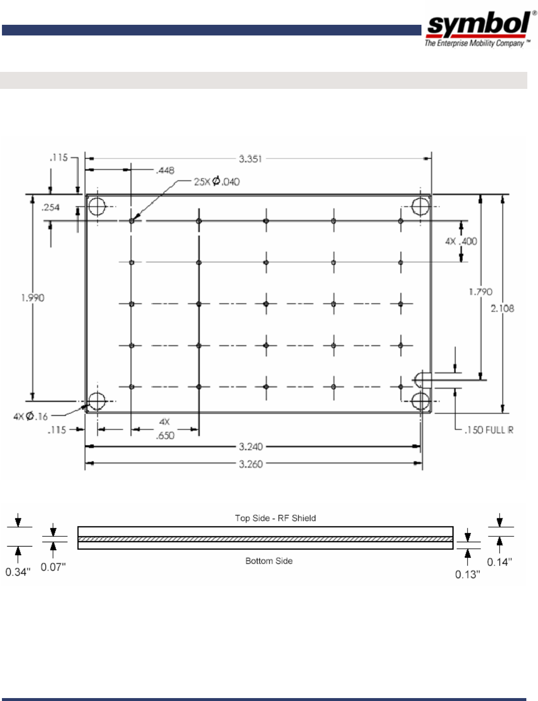
Dimensions Length 3.4” x Width 2.1” x Height 0.3” (85.6 mm x 54 mm x 8 mm)
Weight ~ 2.5 Ounces (70 Grams)
Visual Status Indicator On-board LED for Radio On/Off indication
A.2. Power
Power Supply +6vDC @ 1.2 Amp (Regulated)
Operational Power Consumption 4.8 Watts (800 mA @ 6V)
Idle Power Consumption
(for Hot Standby) 300 mW (50 mA @ 6V)
A.3. Environmental
Condition Standard Value
Operational: -20° to +60° C (-4° to +140° F)
Temperature IEC 60068-2-1/2/14 Storage: -40° to +85° C (-40° to +185° F)
Humidity IEC 60068-30/56 5-95% Non-condensing
Vibration IEC 60068-2-6
Mechanical (also MIL-STD-202 - 213/B)
Sinusoidal (also MIL-STD-202 - 204/B)
Random (also MIL-STD-1344 - 2005)
A.4. Connectivity
Connector Type JST 14-Pin Connector (Part Number: JST SM14B-SRSS-TB)
Factory Option: Serial or TTL
Data Rate: Variable 19.2 / 38.4 / 57.6 and 115.2
Operational Power Consumption
Data Structures: 8 Data / 1 Stop / No Parity / No Flow Control
RF Connector U.FL (Low Profile 1.9 mm Height, 0.81 mm Dia) Coaxial

Hardware and Technical Specifications MR 100 User Manual Page: 15
MR 100 User Manual
A.5. Interface Pin Outs
Pin Number Signal Dir Description
Pin 1: VIN I Regulated +6Vdc (min/max 5.4v/7v), 1.2A max, 2A fused
Pin 2: VIN I Regulated +6Vdc (min/max 5.4v/7v), 1.2A max, 2A fused
Pin 3: GND I Ground
Pin 4: GND I Ground
Pin 5: GPIO_1 I/O General purpose input or output #1, 3.3V TTL, configurable via board
stuff-in option, default to input.
Pin 6: GPIO_2 I/O General purpose input or output #2, 3.3V TTL, configurable via board
stuff-in option, default to input
Pin 7: GPIO_3 I/O General purpose input or output #3, 3.3V TTL, configurable via board
stuff-in option, default to input
Pin 8: GPO_0 O General purpose output #0, 3.3V TTL
Pin 9: GPI_0 I General purpose input #0, 3.3V TTL
Pin 10: RS-232-RxD I RS-232 Receive Data, configurable as host interface via board stuff-in
option
Pin 11: RS-232 TxD O RS-232 Transmit Data, configurable as host interface via board stuff-
in option
Pin 12: GND I Ground
Pin 13: TTL-RxD I 3.3V TTL Receive Data, 5V tolerant, default host interface
Pin 14: TTL-TxD O 3.3V TTL Transmit Data, 5V tolerant, default host interface
A.6. Operational Features
Frequency UHF band, 902-928 MHz
Method Frequency Hopping Spread Spectrum (FHSS); Host controlled On/Off of FH
Power Output Max 1 Watt (30 dBm, host adjustable in steps of 0.1 dB)
Read Range Typical 10’ (in free space using an antenna with 6 dBi gain)
Write Range Typical 4’ (in free space using an antenna with 6dBi gain)
A.7. Compliance
Safety EM / RF Emissions
Regulatory Region 1, FCC Part 15
Physical Dimensions MR 100 User Manual Page: 16
MR 100 User Manual
B. PHYSICAL DIMENSIONS
This section provides detailed diagram physical dimensions of the MR 100.
B.1. Top View
B.2. Side View
Physical Dimensions MR 100 User Manual Page: 17
MR 100 User Manual
B.3. Bottom View
Note: Unit Of Measurement used in above diagrams is inches.
Compliance & Regulatory Information MR 100 User Manual Page: 18
MR 100 User Manual
C. COMPLIANCE & REGULATORY INFORMATION
All Symbol devices are designed to be compliant with rules and regulations in locations they are sold and will be
labeled as required.
Any changes or modifications to Symbol Technologies equipment, not expressly approved by Symbol
Technologies, could void the user’s authority to operate the equipment.
Antennas: Use only the supplied or an approved replacement antenna. Unauthorized antennas, modifications,
or attachments could cause damage and may violate regulations.
FCC RF EXPOSURE GUIDELINES
C.1. Safety Information
The device complies with Internationally recognised standards covering Specific Absorption Rate (SAR) related
to human exposure to electromagnetic fields from radio devices.
C.2. Reducing RF Exposure
It is advisable to use the device only in the normal operating position and it is recomended that no part of the
human body be allowed to come too close to the antenna during operation of the equipment. The unit has been
evaluated and found to comply with the required Maximum Permissable Exposure limits at 20cm.
C.3. Hand Held / Wrist Worn Devices
This device is not certified for use as is in handheld devices. Such use will require additional testing and
certification.
C.4. Radio Frequency Interference Requirements-FCC
Note: This equipment has been tested and found to comply with the limits for a Class B digital device, pursuant
to Part 15 of the FCC rules. These limits are designed to provide reasonable protection against harmful
interference in a residential installation. This equipment generates, uses and can radiate radio frequency
energy and, if not installed and used in accordance with the instructions, may cause harmful interference to
radio communications. However there is no guarantee that interference will not occur in a particular
installation. If this equipment does cause harmful interference to radio or television reception, which can be

Compliance & Regulatory Information MR 100 User Manual Page: 19
MR 100 User Manual
determined by turning the equipment off and on, the user is encouraged to try to correct the interference by
one or more of the following measures:
• Reorient or relocate the receiving antenna
• Increase the separation between the equipment and receiver
• Connect the equipment into an outlet on a circuit different from that to which the receiver is connected
• Consult the dealer or an experienced radio/TV technician for help.
C.5. Radio Transmitters (Part 15)
This device complies with Part 15 of the FCC Rules. Operation is subject to the following two conditions: (1)
this device may not cause harmful interference, and (2) this device must accept any interference received,
including interference that may cause undesired operation.
C.6. Radio Frequency Interference Requirements – Canada
This Class B digital apparatus complies with Canadian ICES-003.
Cet appareil numérique de la classe B est conforme à la norme NMB-003 du Canada.
Radio Transmitters
This device complies with RSS 210 of Industry & Science Canada. Operation is subject to the following two
conditions: (1) this device may not cause harmful interference and (2) this device must accept any interference
received, including interference that may cause undesired operation.
Label Marking: The Term "IC:" before the radio certification only signifies that Industry Canada technical
specifications were met.
C.7 Regulatory
Symbol’s devices are designed to be compliant with rules and regulations in locations they are sold and are labeled
as required.
Any changes or modifications to Symbol Technologies equipment, not expressly approved by Symbol
Technologies, could void the user’s authority to operate the equipment.
Final Product Compliance
Final product will require Regulatory approvals; these include Product Safety, EMC, and SAR etc. As the integrator
it is your responsibility to comply with these requirements for each country in which the product is sold. The
compliance process may include submittal of prototype products for test purposes. Be prepared, the certification
process for your product may take from a few weeks to several months. Symbol advises the use of an accredited
test laboratory for advice and testing or the final product.

Compliance & Regulatory Information MR 100 User Manual Page: 20
MR 100 User Manual
United States
This module is approved for integration; to maintain the approval the integrator must address the following:
• FCC Part 15 (emissions class B) required for the final product
• SAR testing required on final product (Note: If final product, in normal usage, is operated more than 20cm from
the human body, MPE testing is required instead of SAR)
Final product markings must include:
• Contains FCC ID: H9PMR100A
Canada
In complying with the requirements for the FCC, this device also complies with all the technical requirements of
the Canadian Interference-Causing Equipment Regulations (ICES-003).
Final product markings must include:
• Contains IC: 1549D-MR100A