Symbol Technologies PDT687C Portable Data Terminal w/WLAN PC Module User Manual 3264502a
Symbol Technologies Inc Portable Data Terminal w/WLAN PC Module 3264502a
Contents
- 1. Product Reference Guide
- 2. Quick Reference Guide
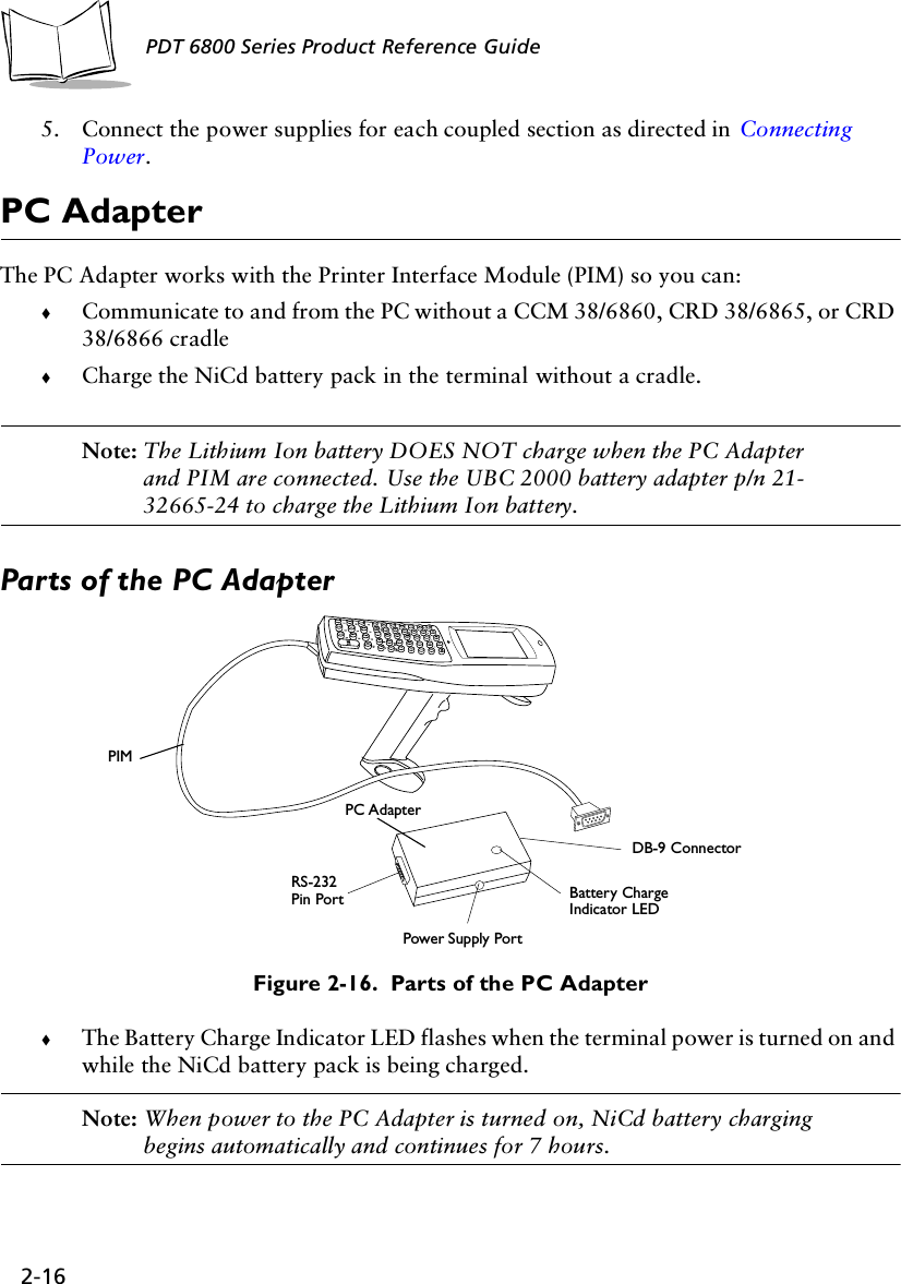
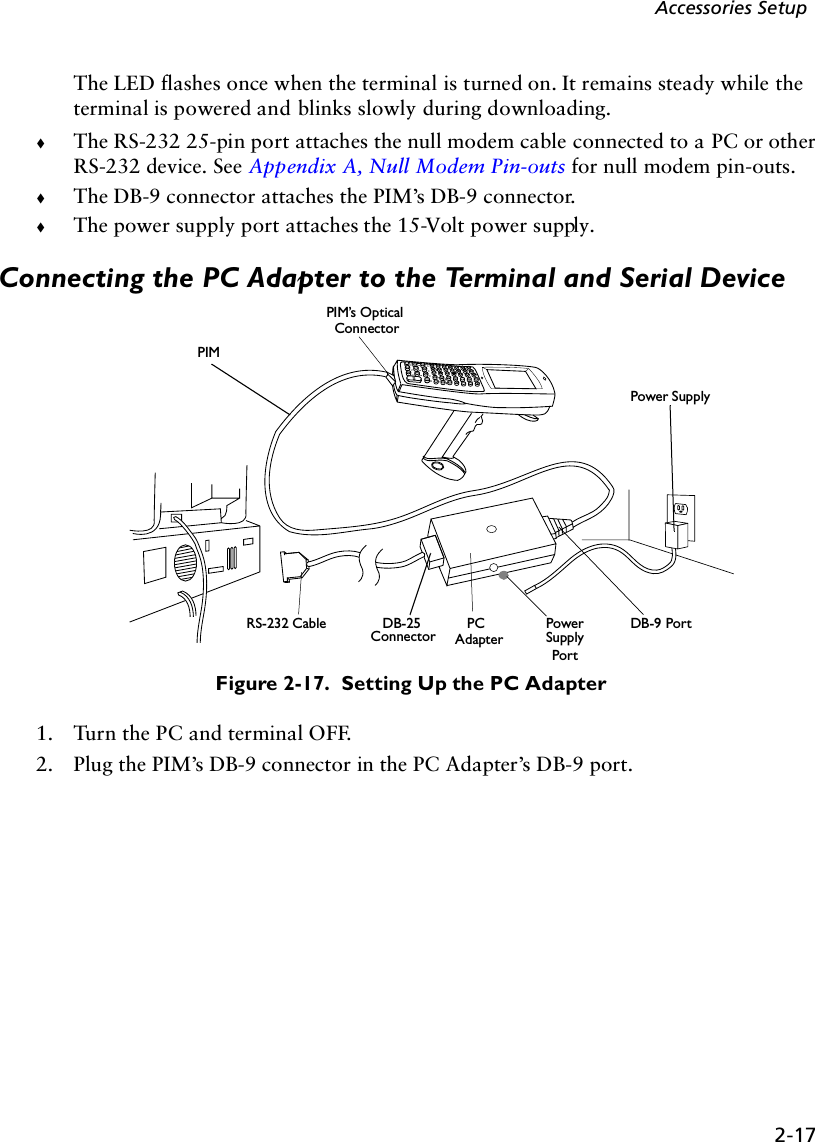
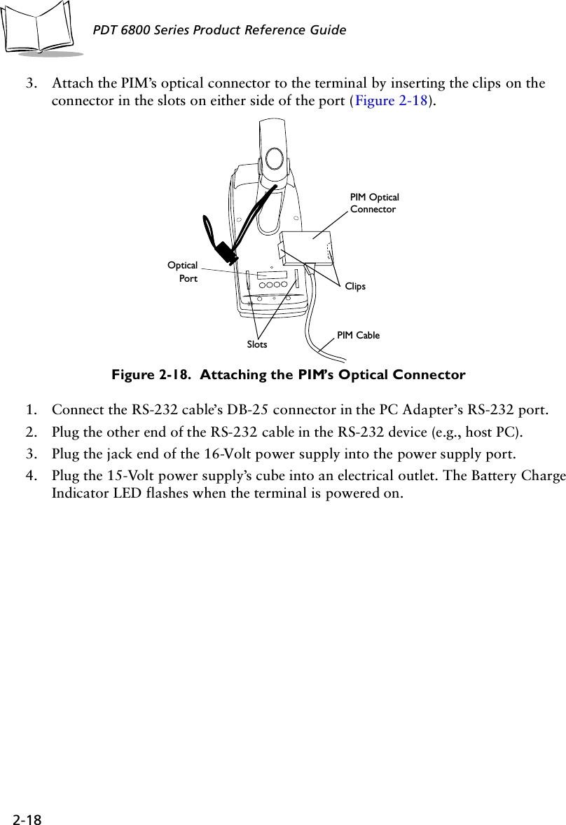
- 3. GRG Addendum
Product Reference Guide
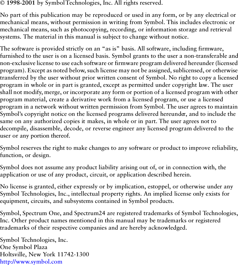

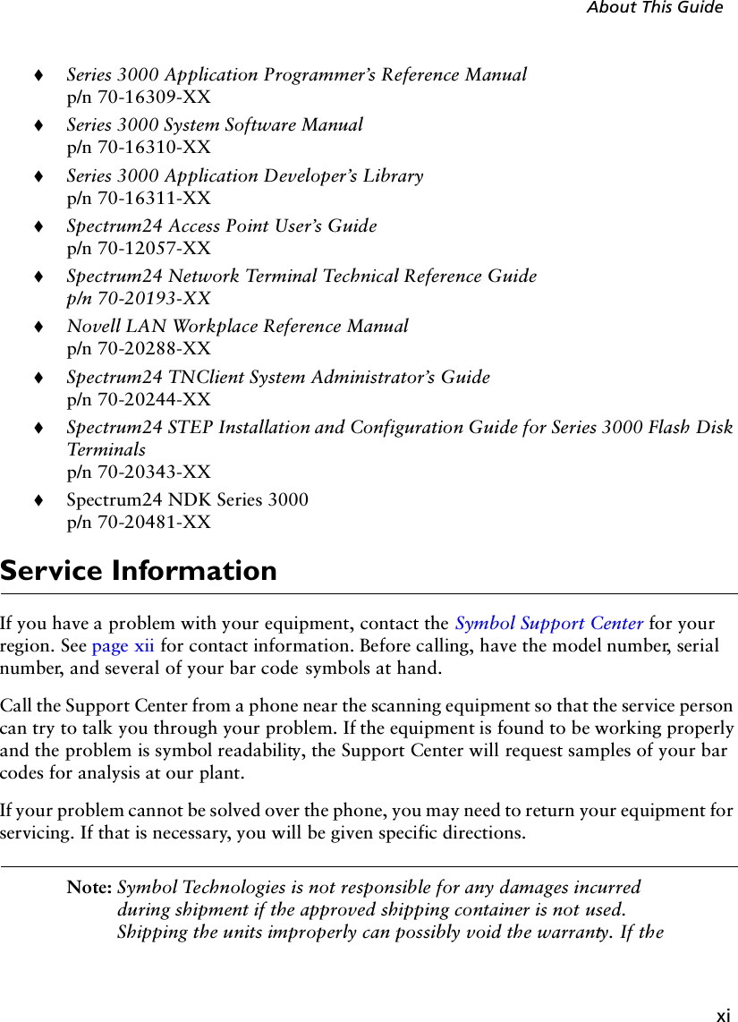
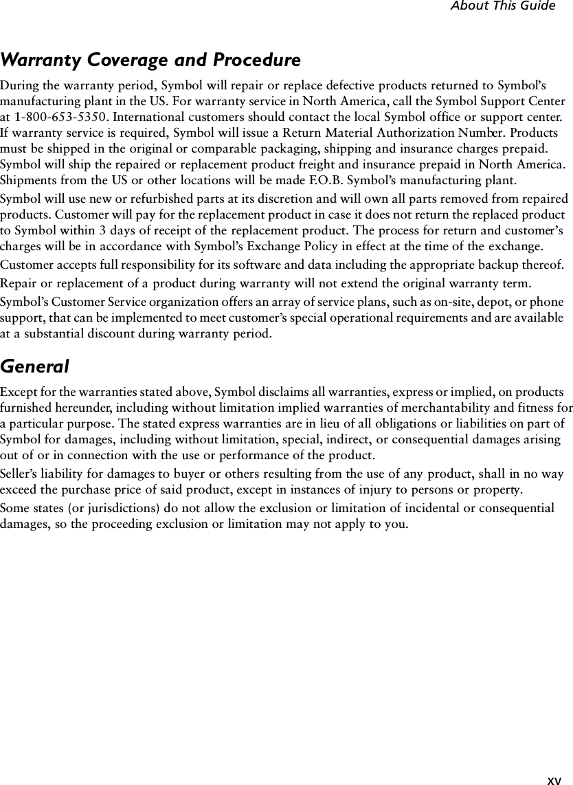

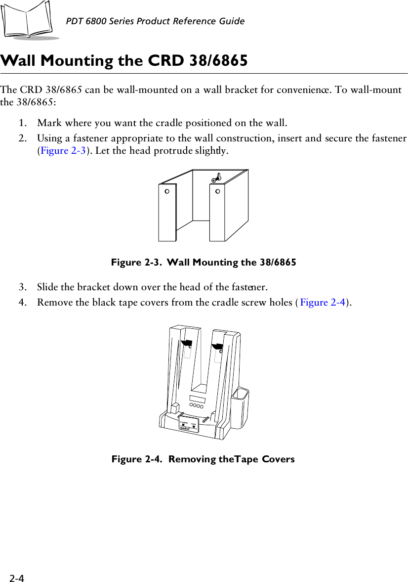
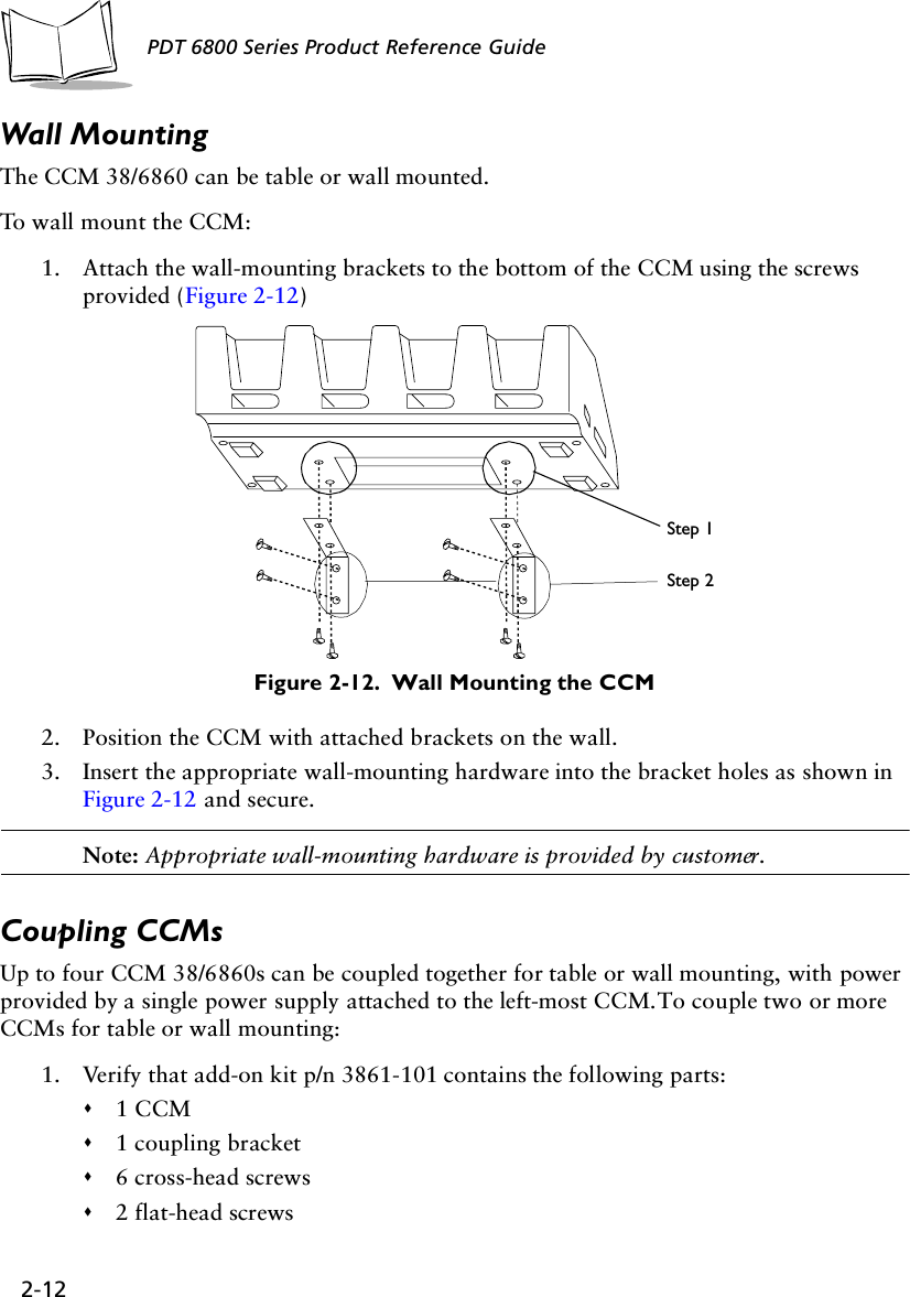
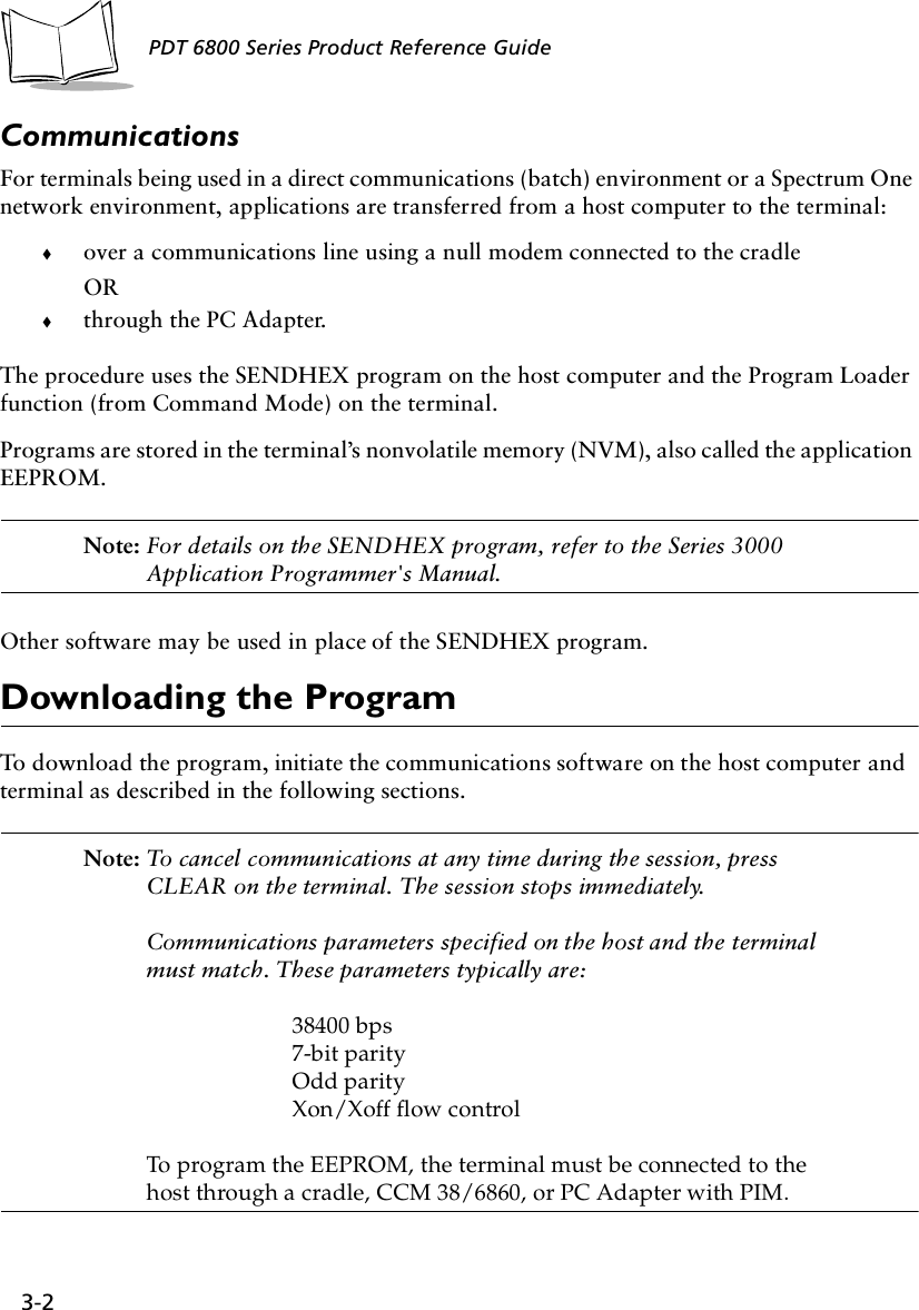
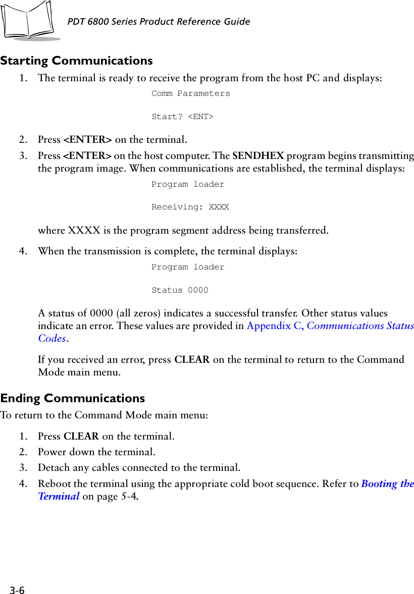

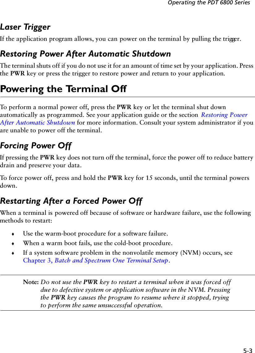

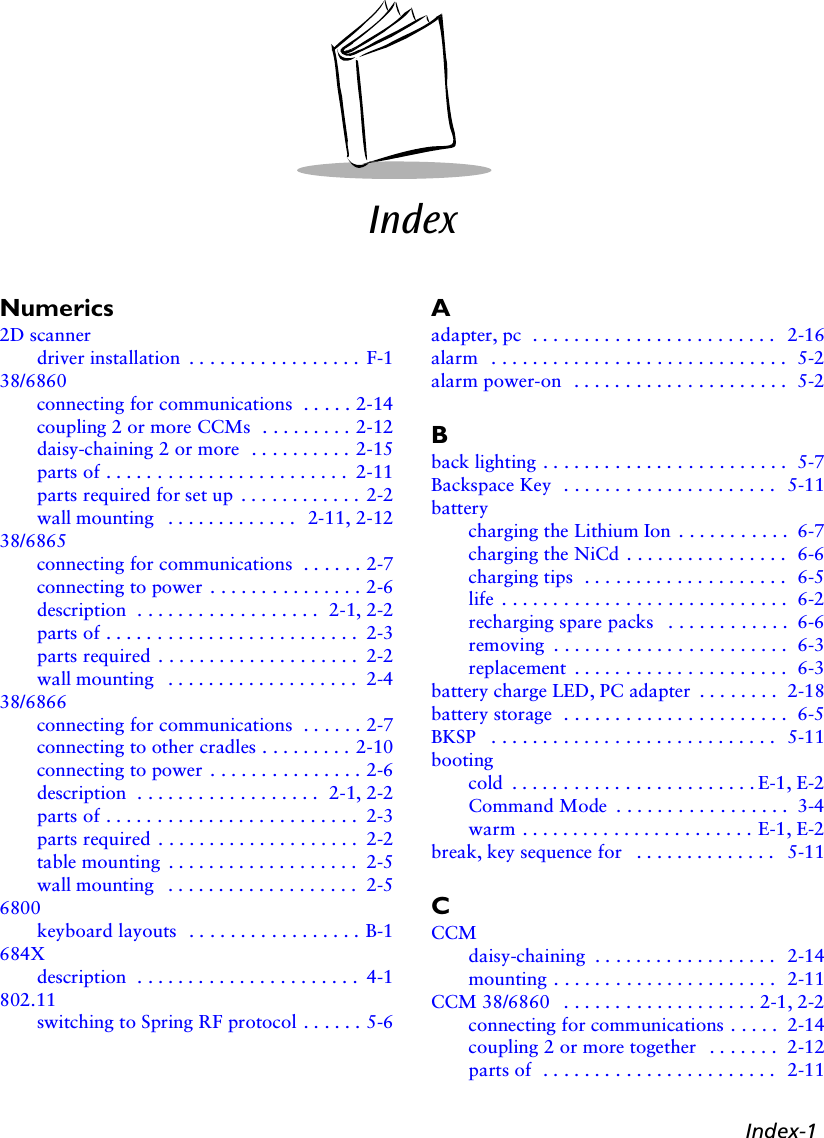
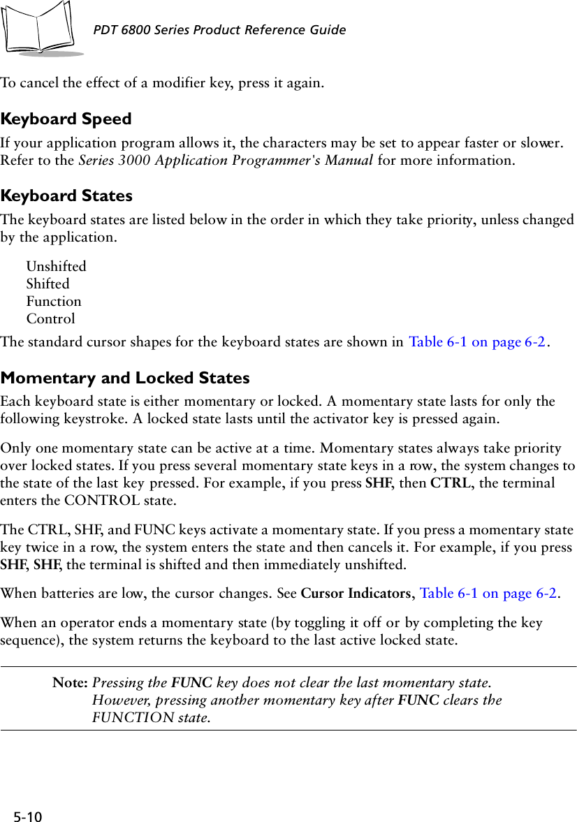
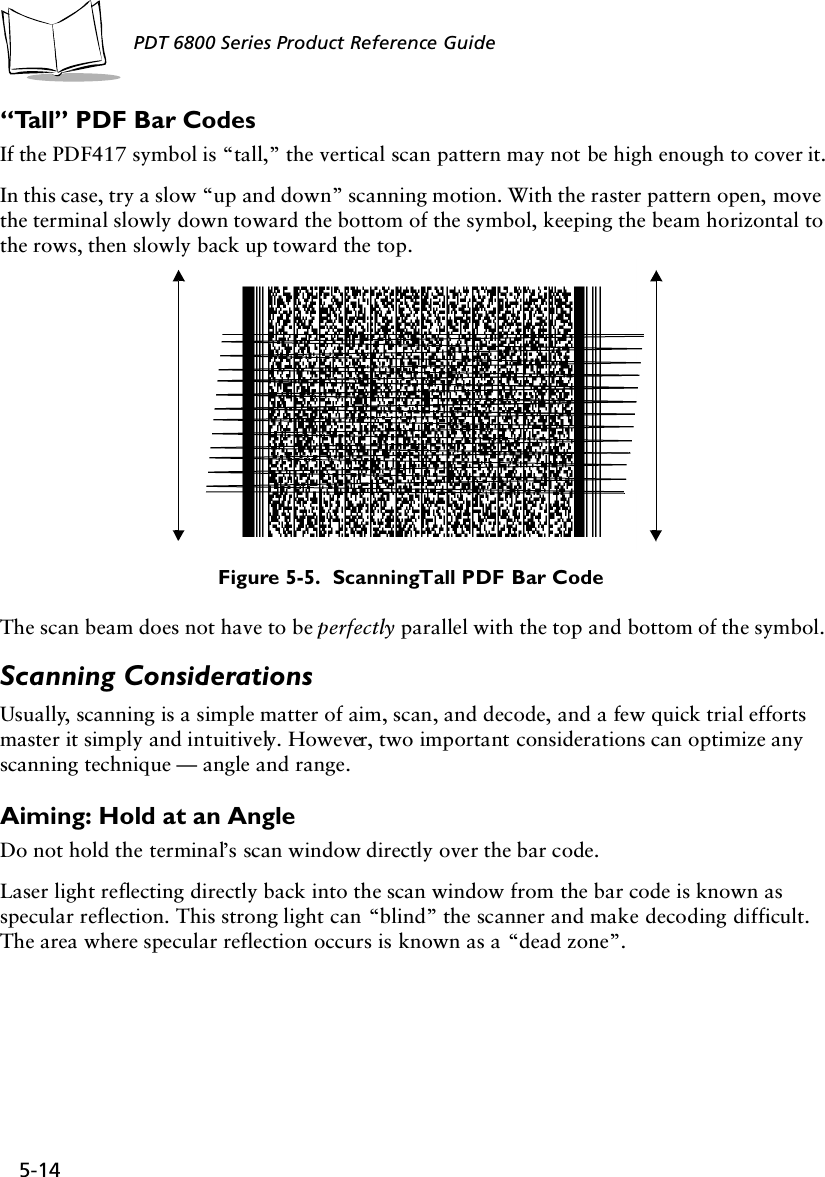
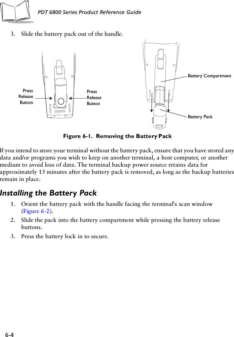
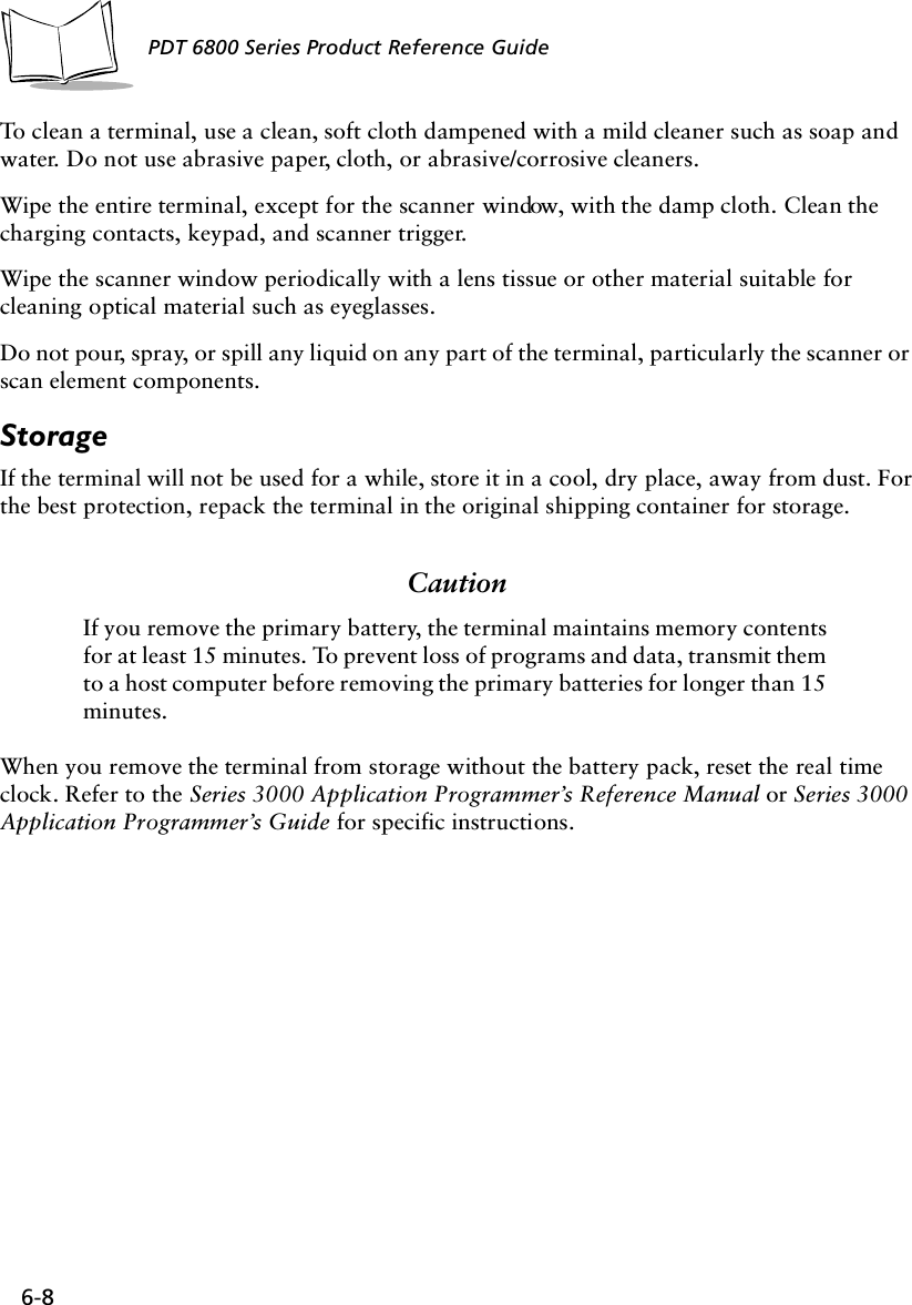
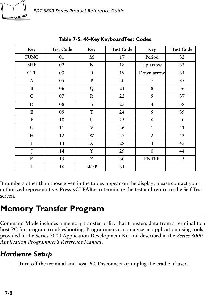
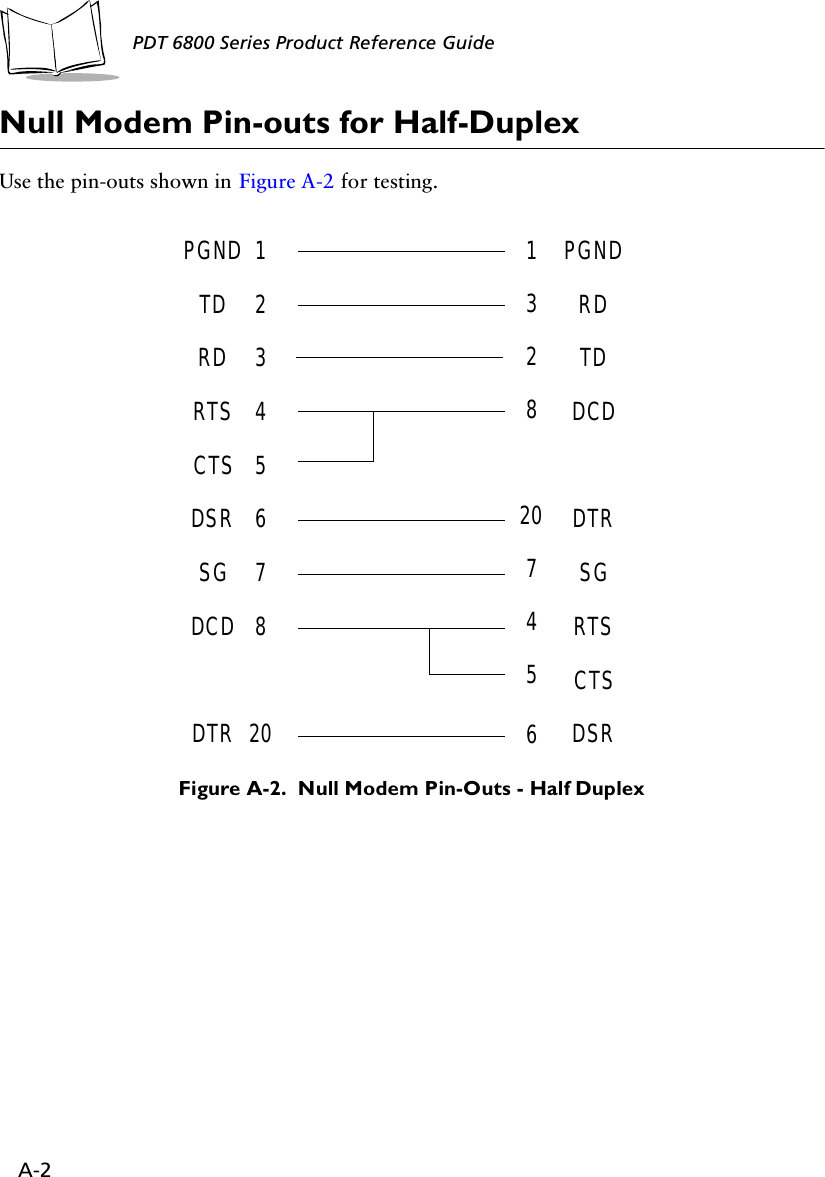
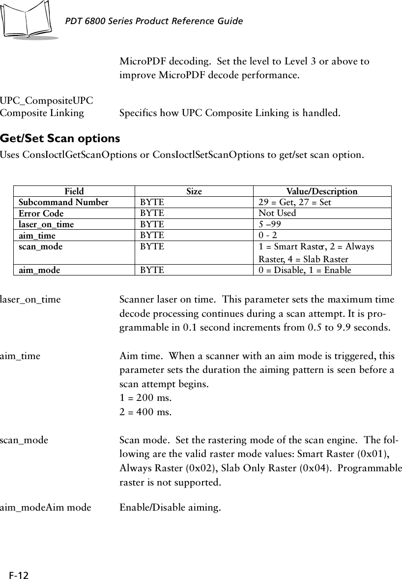
![5-6PDT 6800 Series Product Reference GuidePDT 6842 - Switching 802.11 to Spring RF ProtocolAfter a cold boot, the PDT 6842 boots up with the 802.11 RF protocol. If you are using the Spring RF protocol, do the following to switch from 802.11 to Spring:1. Cold boot the terminal. The following prompt displays:SOFTWARE UPDATEUpdate?[y/n]:2. Within four seconds, type the letter “y”. If you do not type the letter “y” within four seconds, the terminal boots up with the 802.11 RF protocol.The next prompt displays:RF PROTOCOL UPDATEOPPORTUNITYUpdate RF protocol[y/n]:3. Within ten seconds, type the letter “y”. If you do not type the letter “y” within ten seconds, the terminal boots up with the 802.11 RF protocol.The next prompt displays:RF ProtocolCurrently 802.111. Abort update2. Make pre-802.113. Make 802.11Select[1,2,3]:4. Select 2 to boot up with the Spring RF protocol.The next prompt displays:Enter password→5. Enter the password RFPROT, then press ENTER. The terminal continues to boot up.The procedure to switch to the Spring RF protocol is complete. If a compatibility problem exists, the terminal pauses with an error message. Contact your System Administrator.](https://usermanual.wiki/Symbol-Technologies/PDT687C.Product-Reference-Guide/User-Guide-326978-Page-53.png)
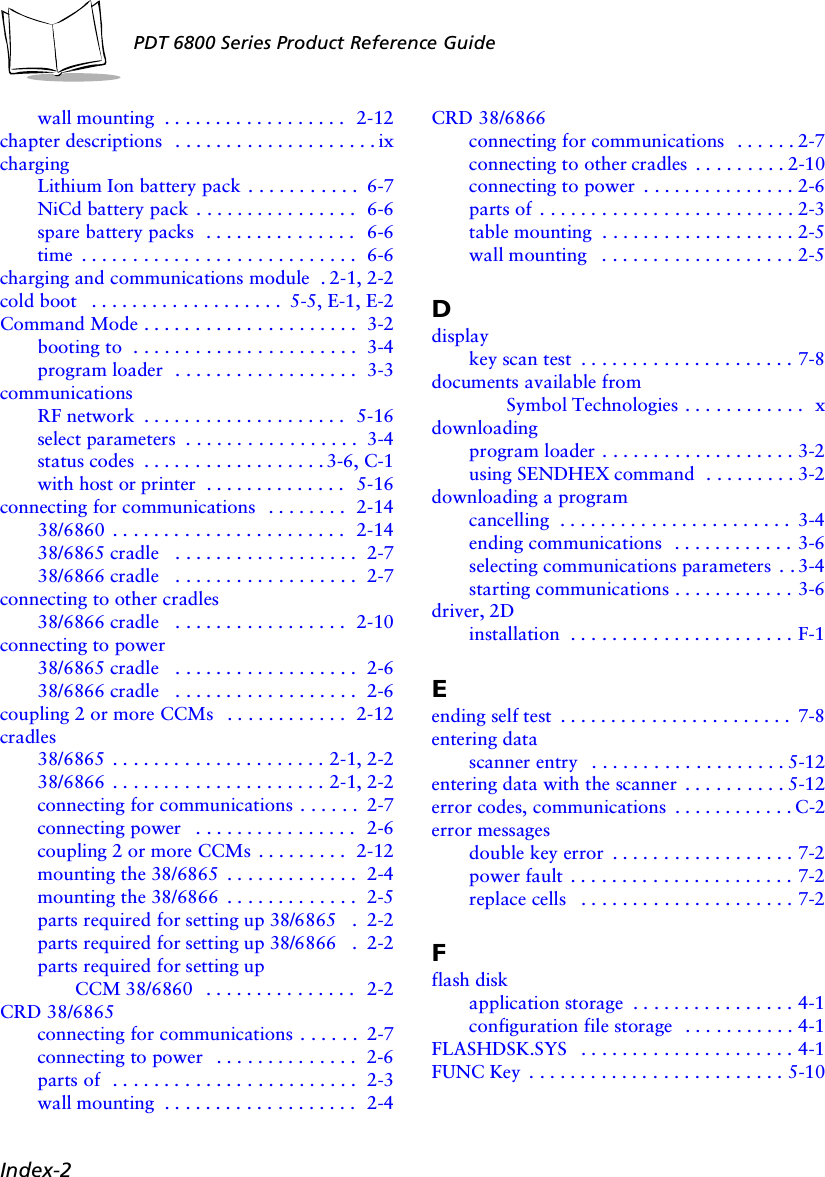
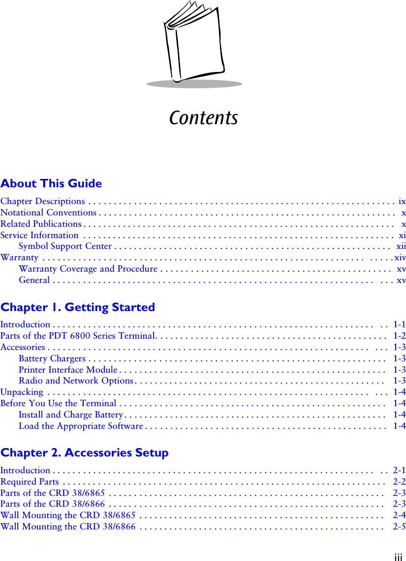
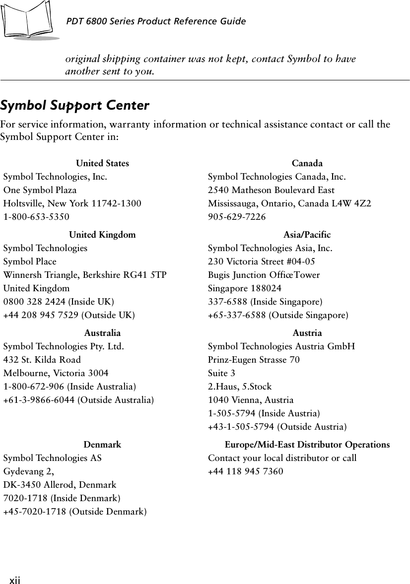
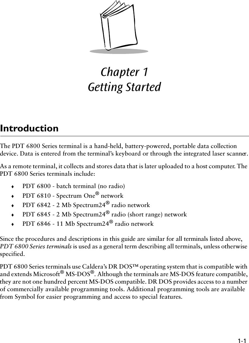
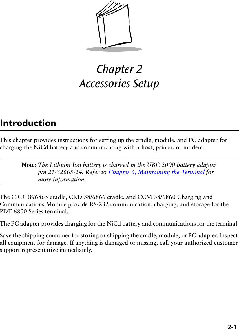
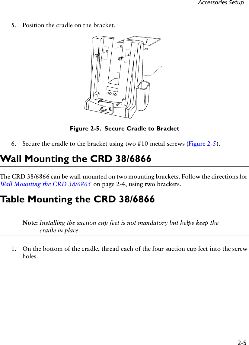
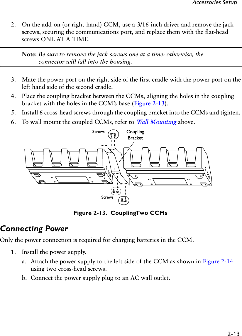
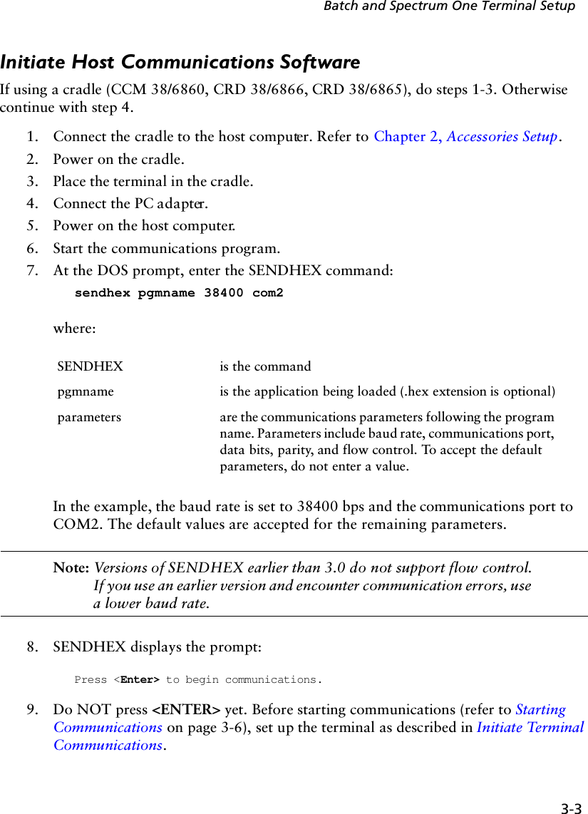
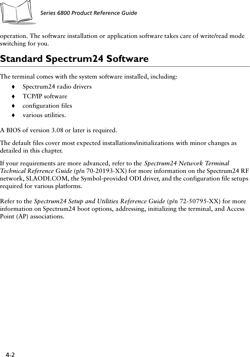
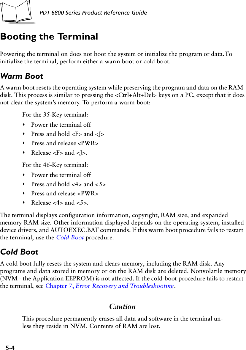
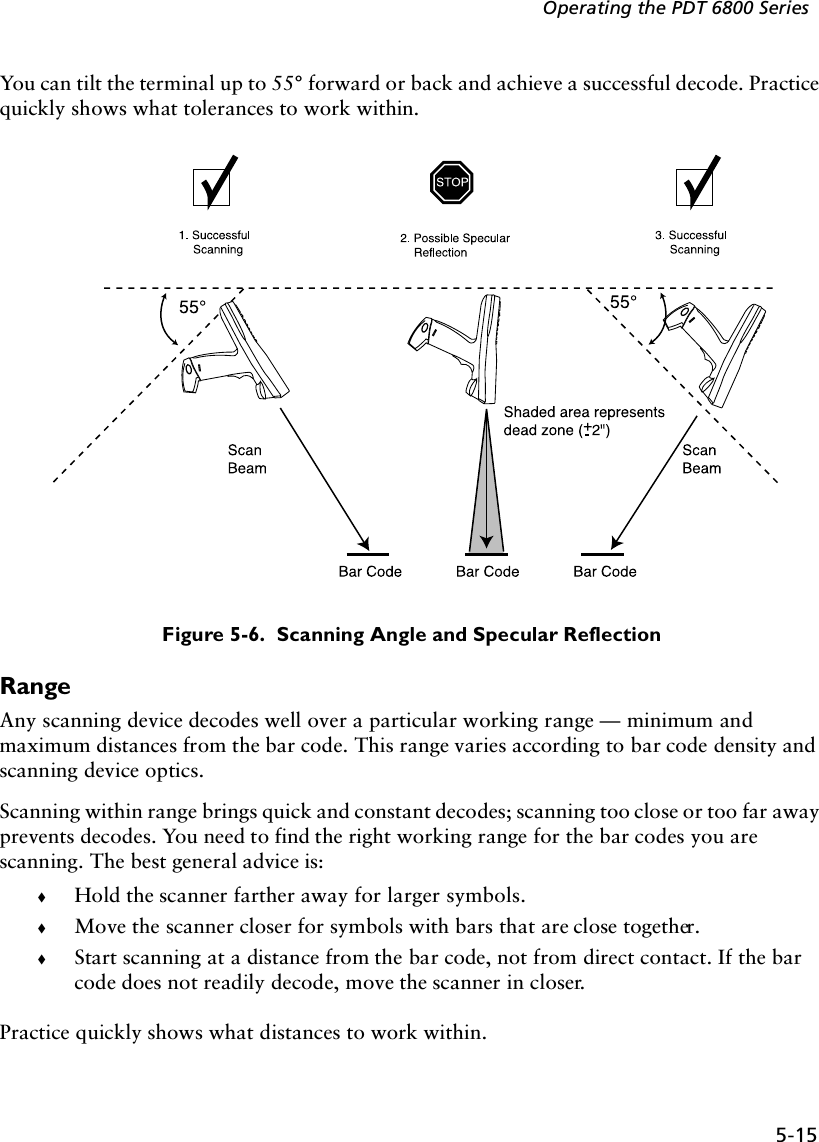
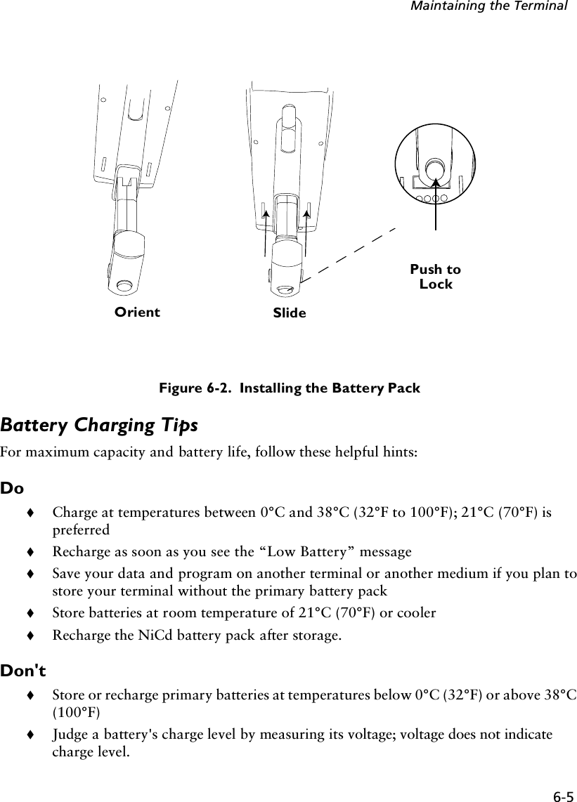
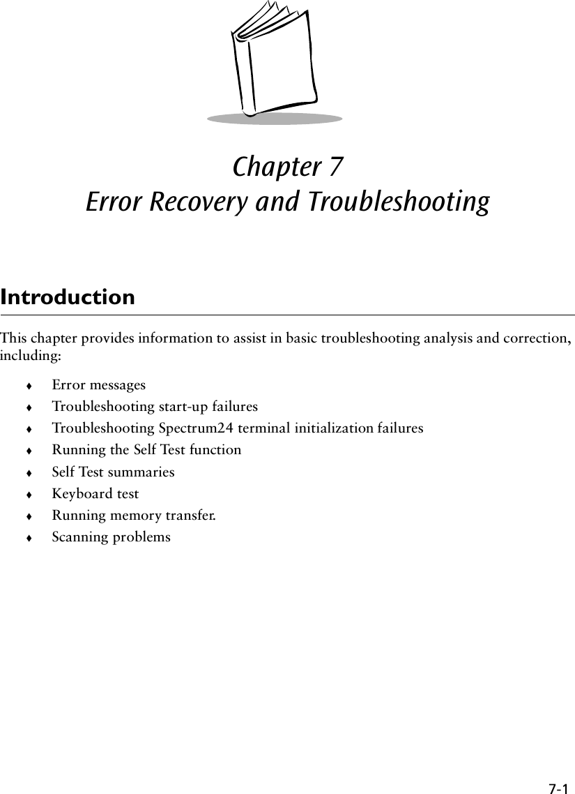
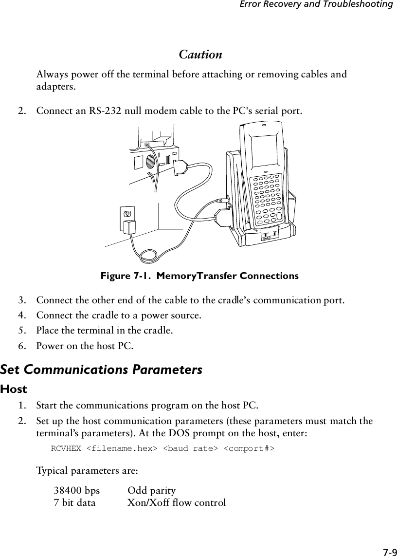
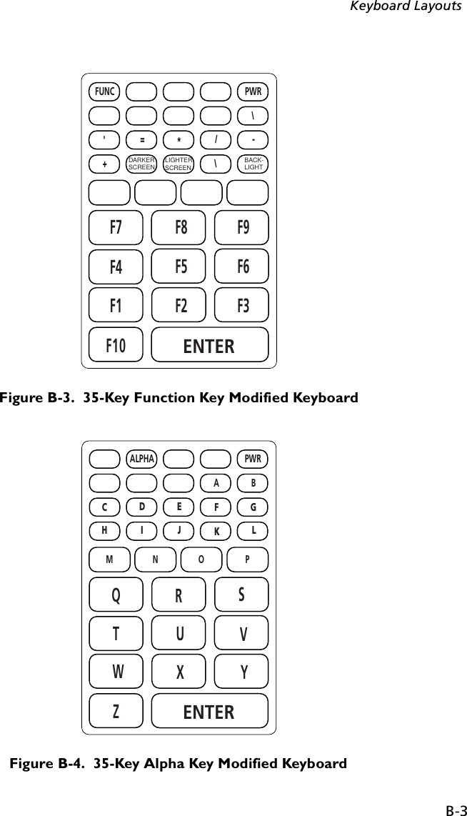
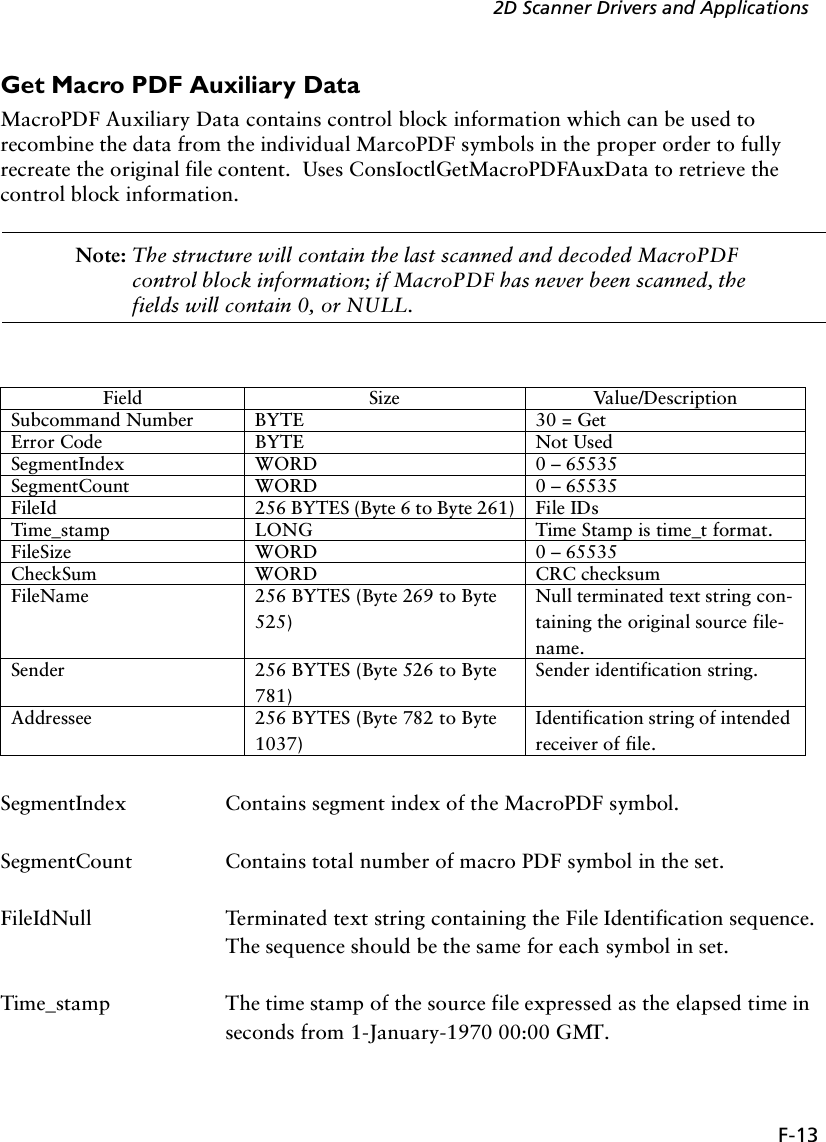
![5-8PDT 6800 Series Product Reference GuideNote: Use of backlighting can significantly reduce battery life.To turn the backlight on or off, press FUNC then L, or use the key sequence listed in your application guide. The backlight turns off automatically when the terminal is powered off or when the terminal has not been used for an amount of time set by the application. See the Series 3000 Application Programmer's Guide for more information.PDT 6800 Series KeyboardThe keyboard is used for entering data and issuing commands to the terminal. Figure 5-1 and Figure 5-2 illustrate the standard 35-key and 46-key keyboards respectively. The keys on the keyboard are distinguished as modifier keys and character keys. Because terminal keyboards have fewer keys than PC keyboards, each character key can produce more than the usual one or two characters. The modifier keys, SHF (Shift), CTL, and FUNC, used individually or in combination, determine which character or special function the character keys produce. Because the keyboard is programmable, your terminal may not work as described here. For more information and illustrations of other keyboard states, see the Series 3000 Application Programmer's Guide and your application guide.Figure 5-1. 35-Key KeyboardENTER0Z123698574F10WTQRUXYVSFUNC ALPHA CLEAR SHIFT PWRBKSP SPACE CTRL [ A ] B' C = D * E / F - G+ H . I , J \ K ; LMNO PF1 F2 F3F6F5F4F9F8F7](https://usermanual.wiki/Symbol-Technologies/PDT687C.Product-Reference-Guide/User-Guide-326978-Page-55.png)
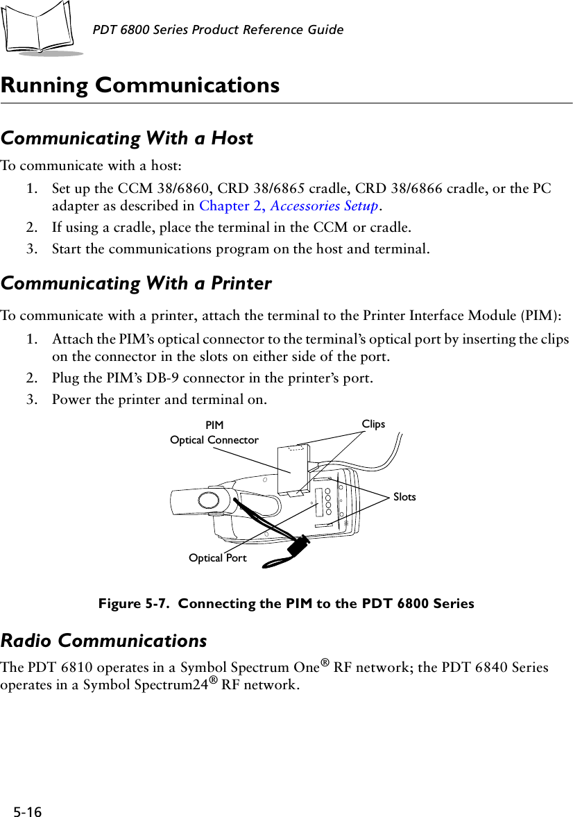
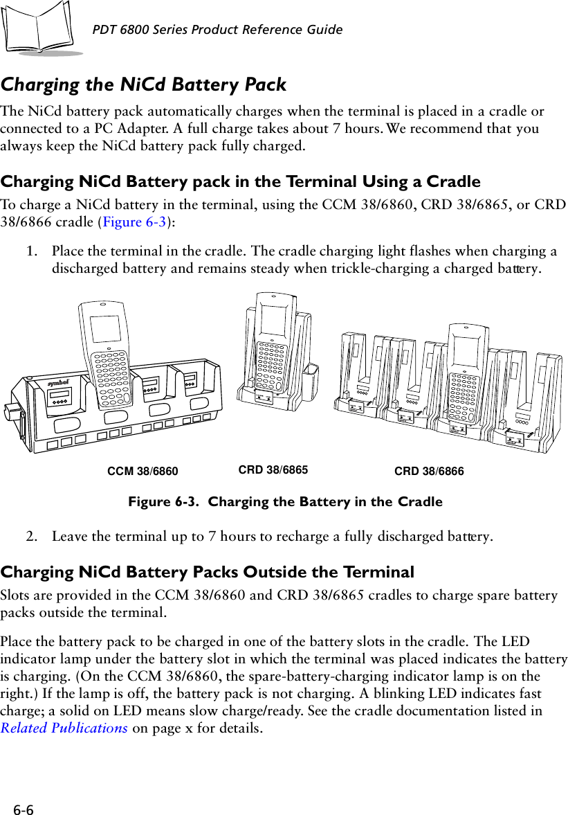
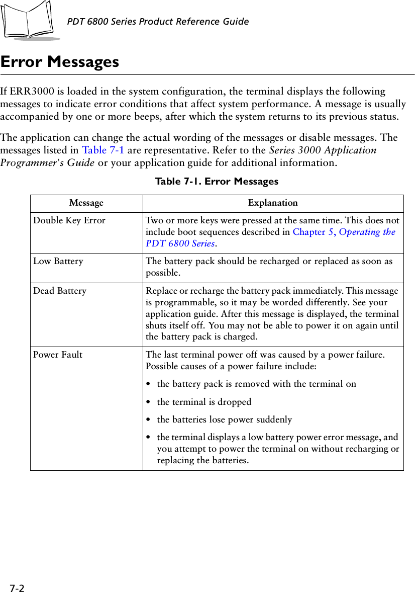
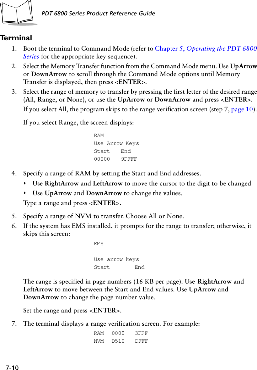
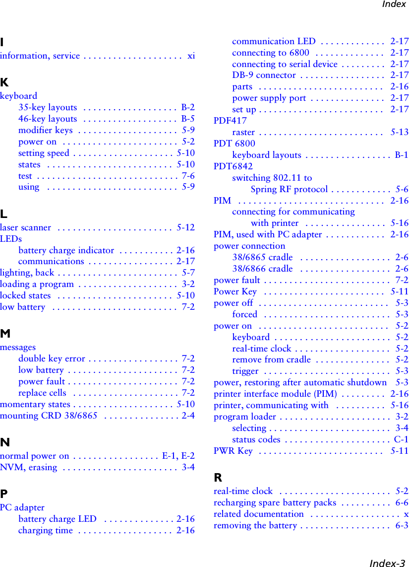
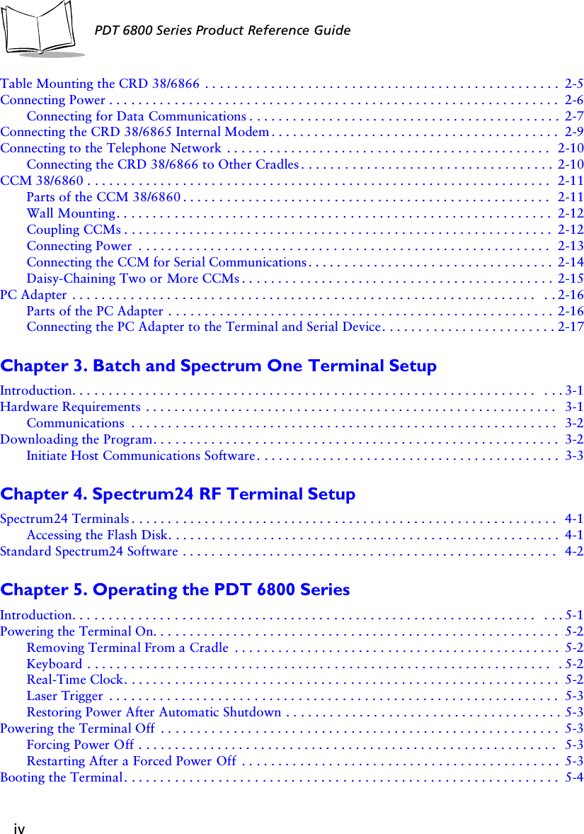
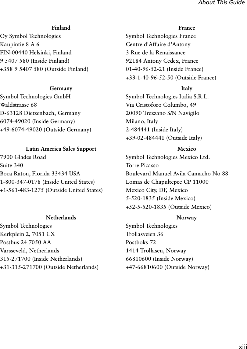
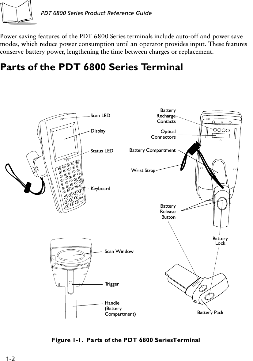
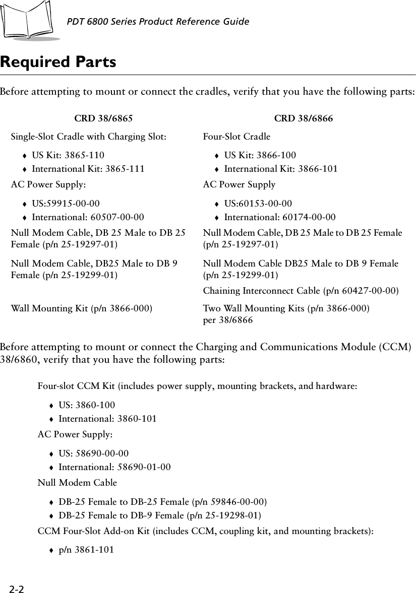
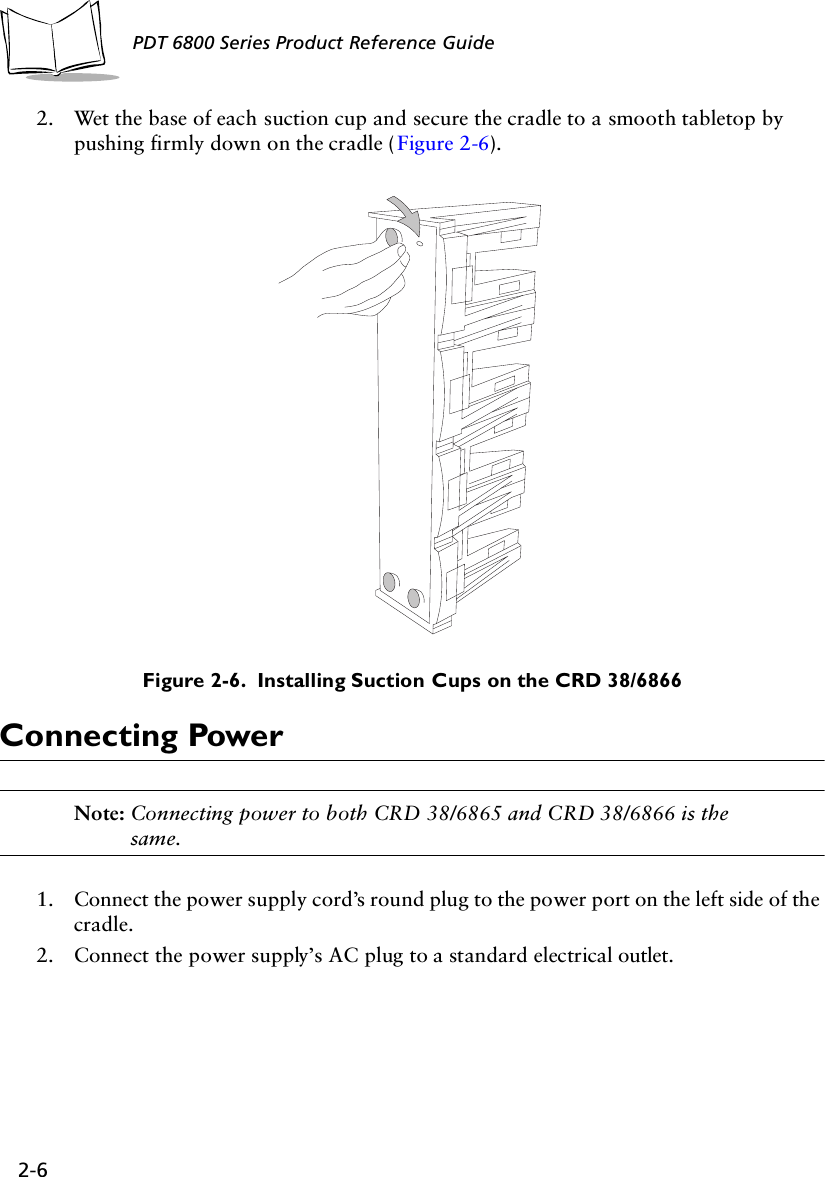
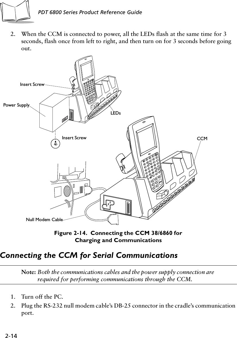
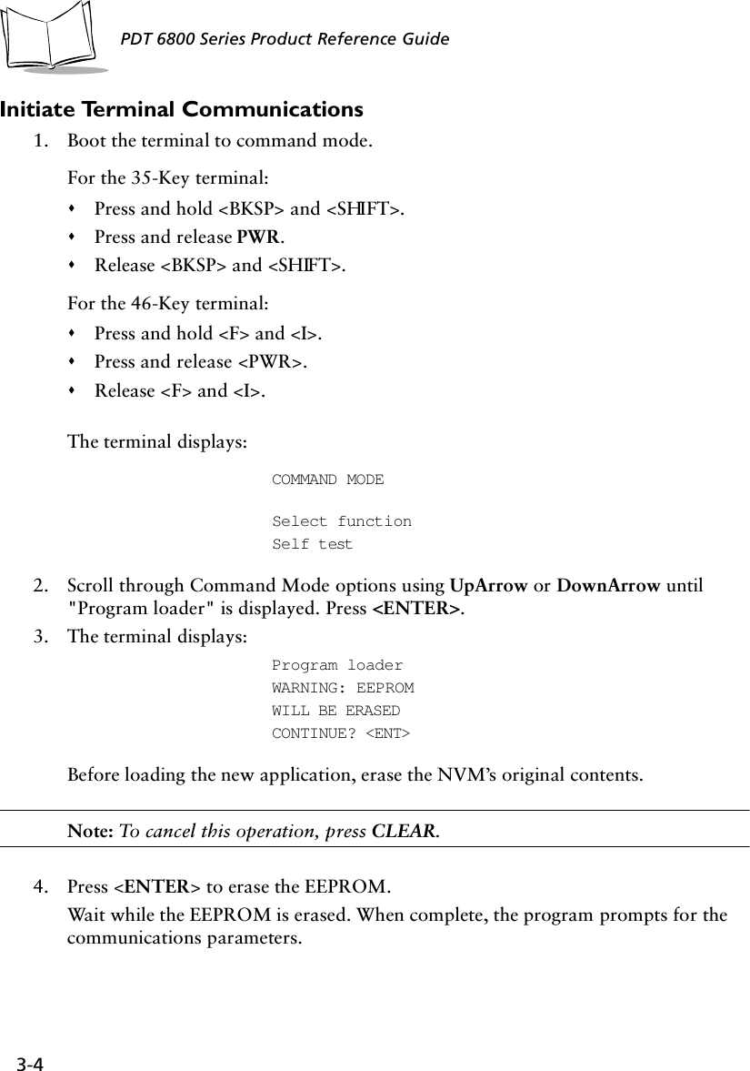
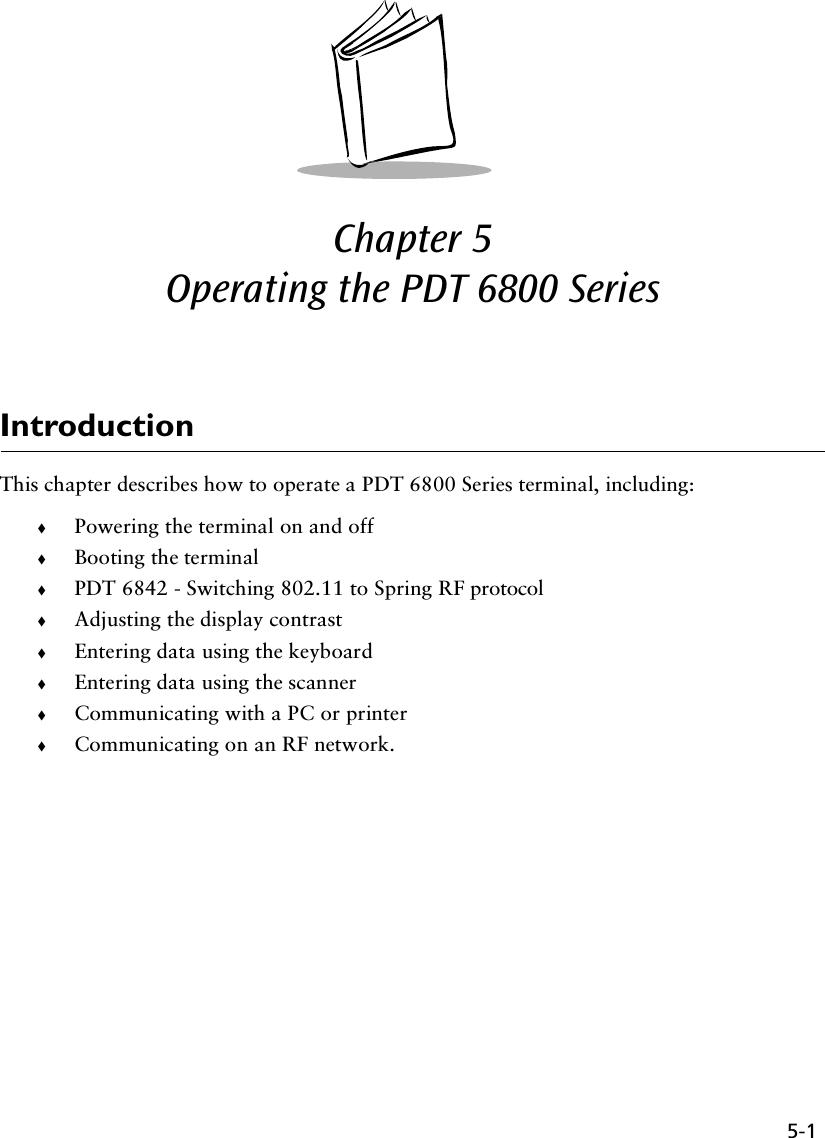
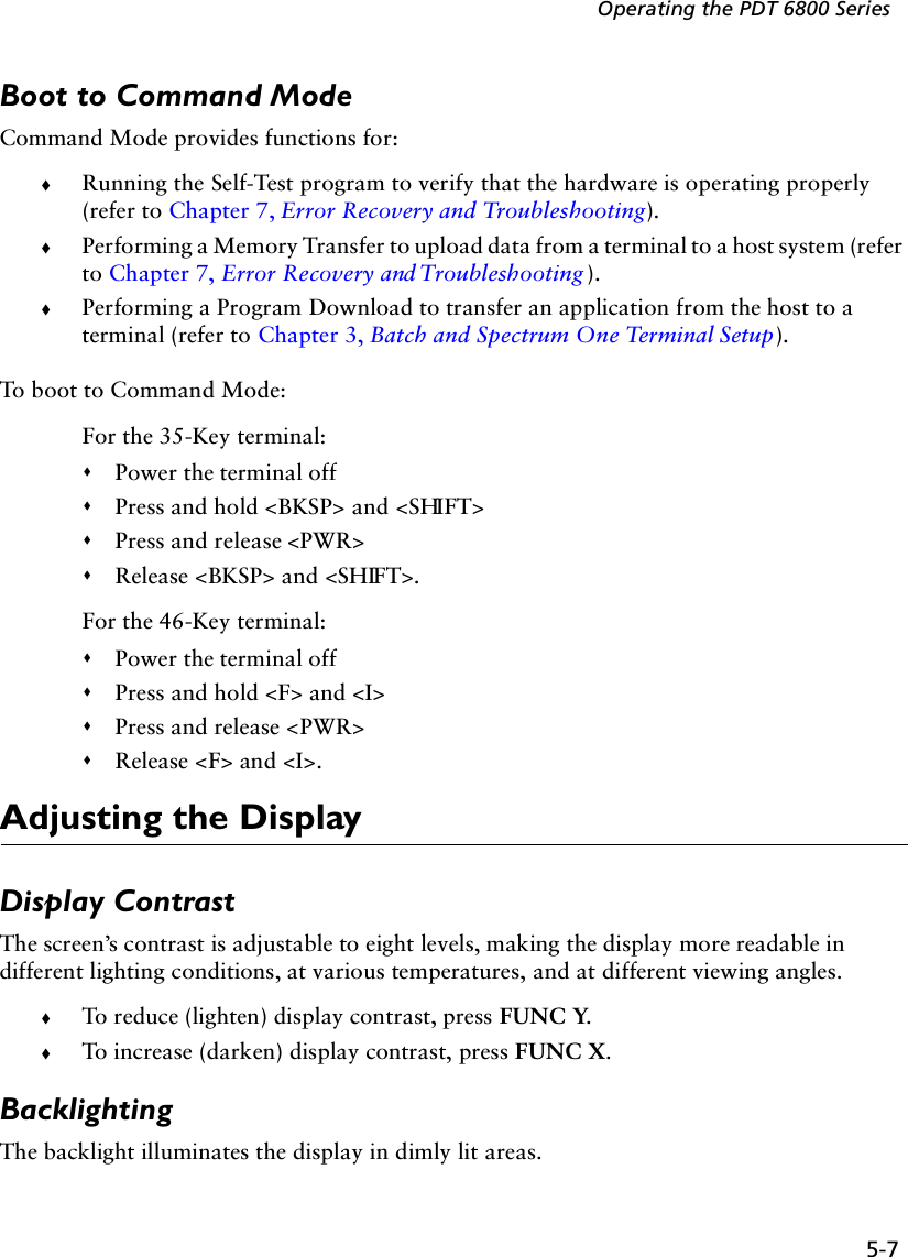
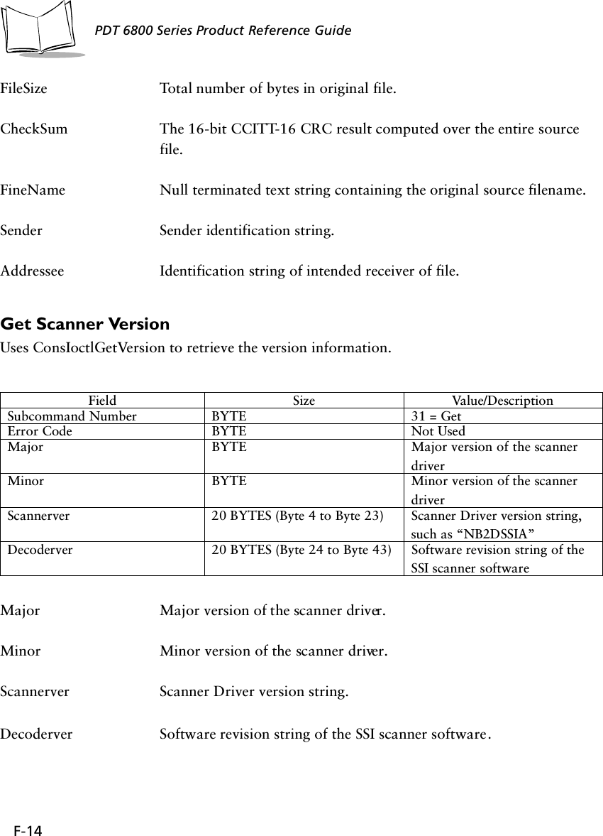
![B-2PDT 6800 Series Product Reference Guide35-Key KeyboardKey definitions can be changed by the application program. The captions indicate what sequence of modifier keys produce the keyboard.Figure B-1. 35-Key PDT 6800 Series KeyboardFigure B-2. 35-Key Unmodified KeyboardENTER0Z123698574F10WTQRUXYVSFUNC ALPHA CLEAR SHIFT PWRBKSP SPACE CTRL [ A ] B' C = D * E / F - G+ H . I , J \ K ; LMNO PF1 F2 F3F6F5F4F9F8F7ENTER0123698574FUNC ALPHA CLEAR SHIFT PWRBKSP SPACE CTRL [ ] ' = * /-+ . , \ ;](https://usermanual.wiki/Symbol-Technologies/PDT687C.Product-Reference-Guide/User-Guide-326978-Page-91.png)
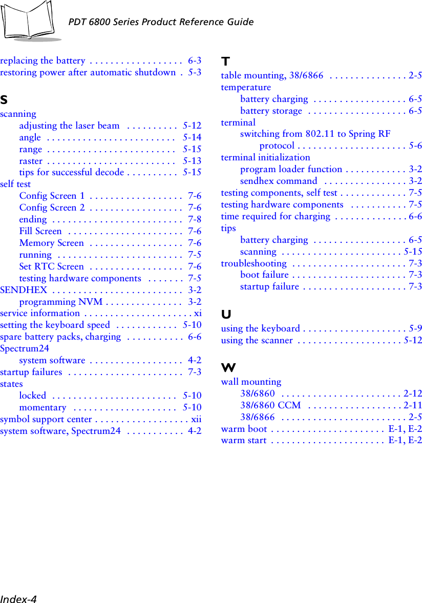
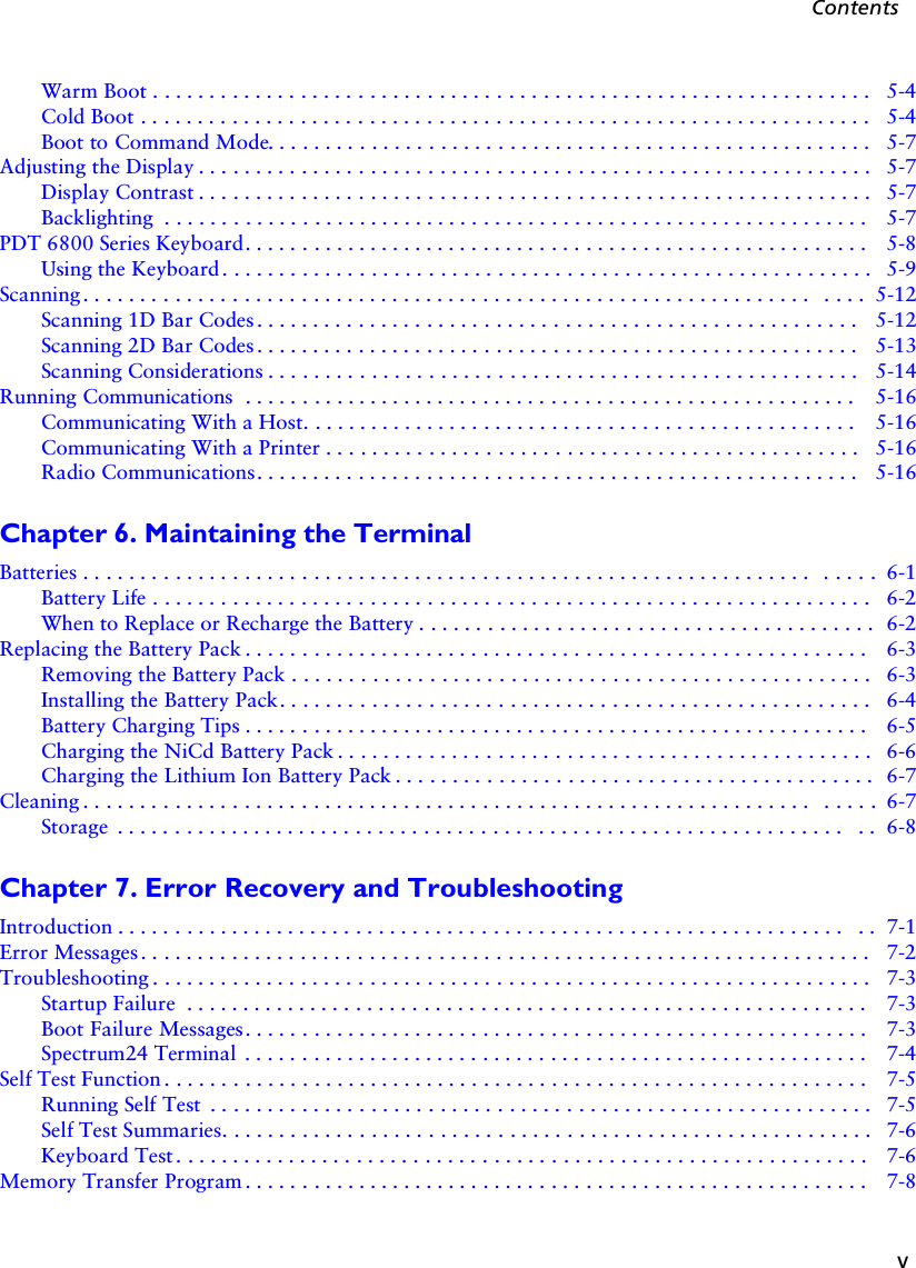
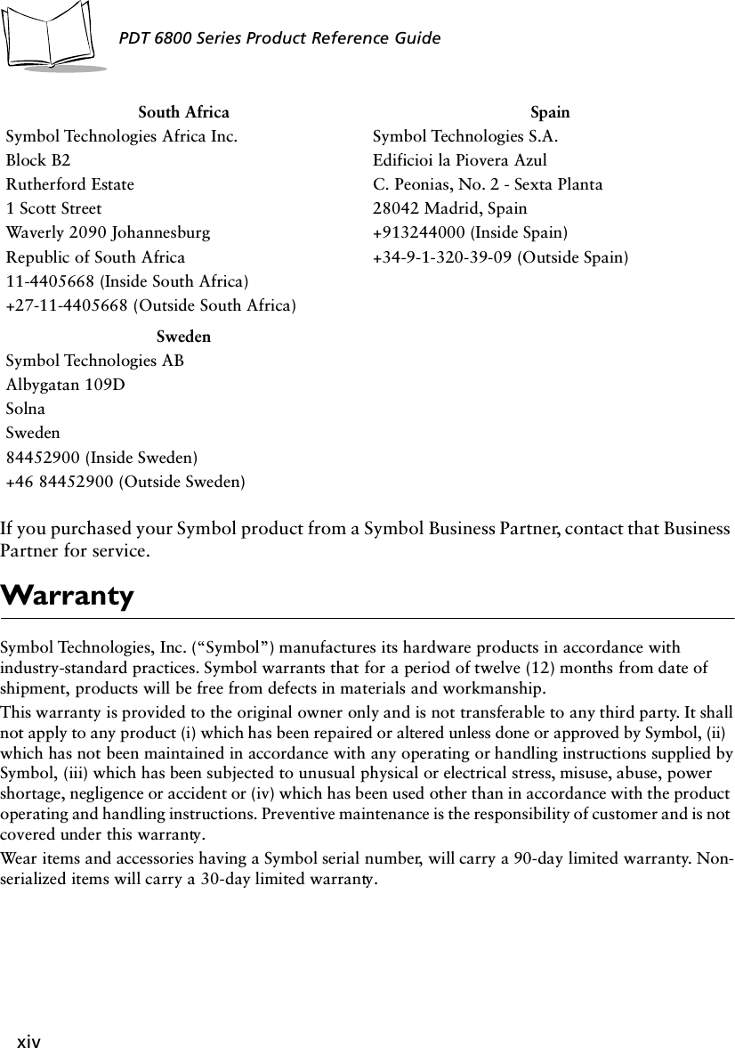
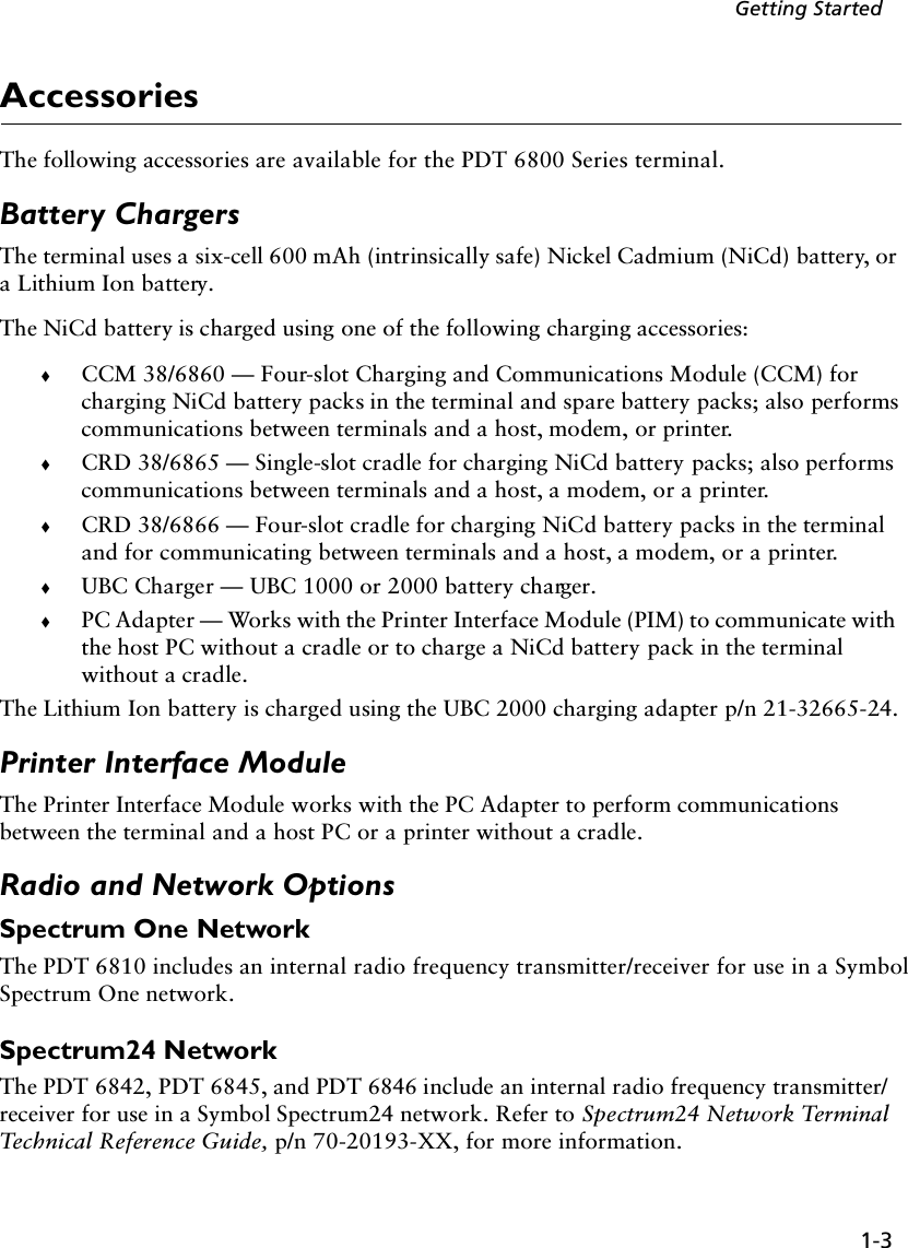
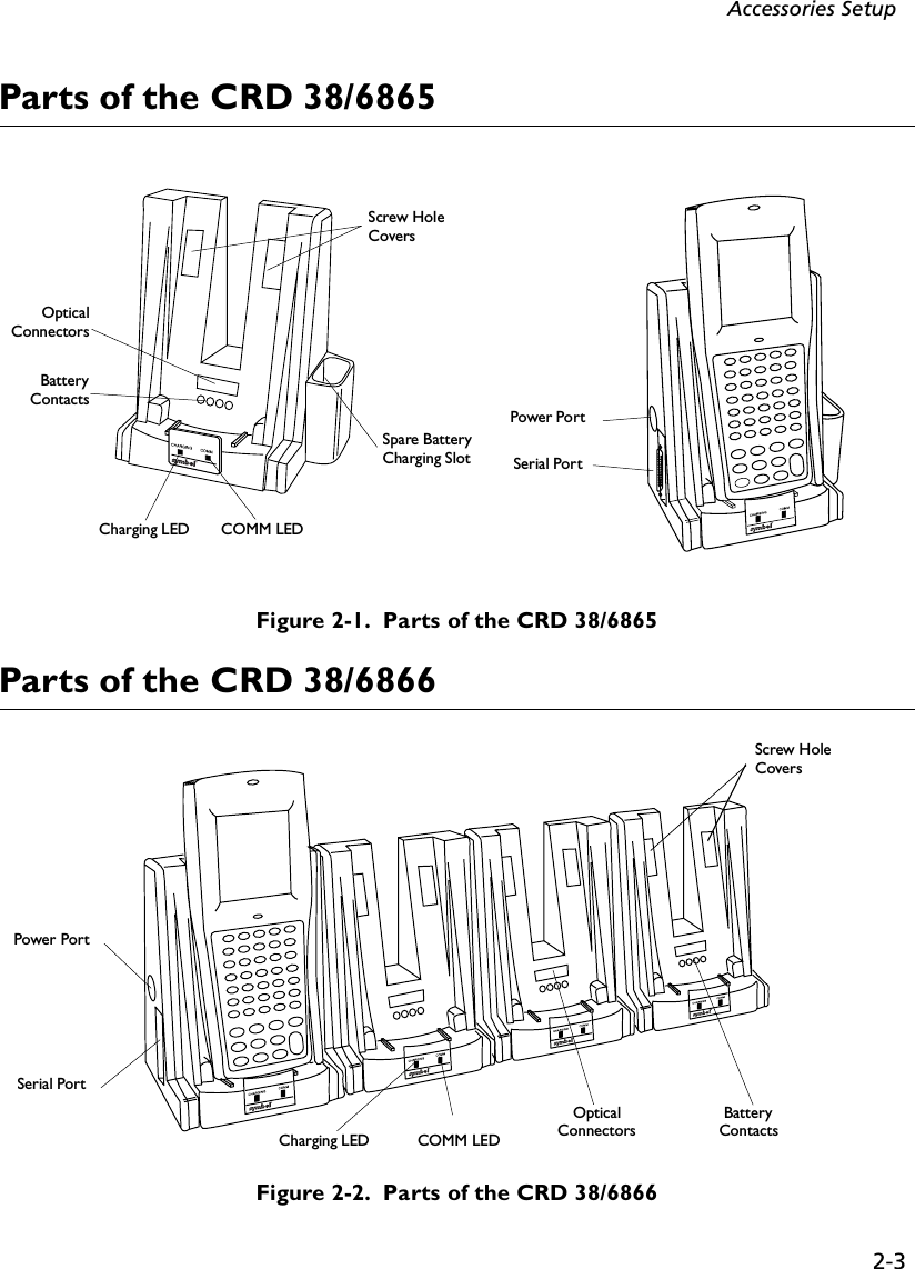
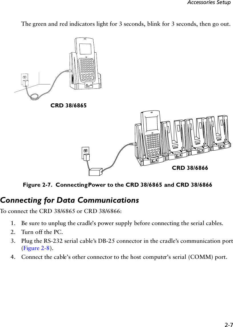
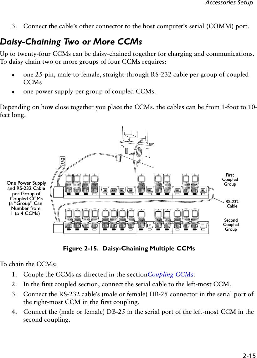
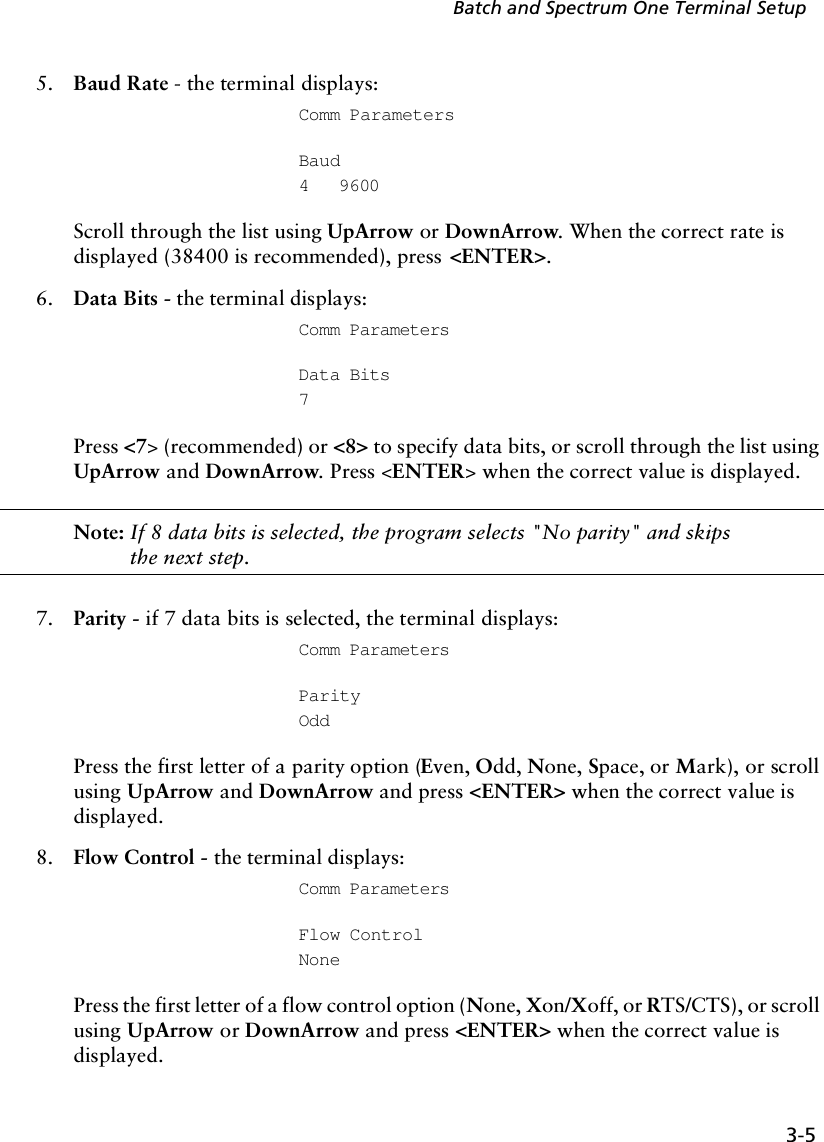
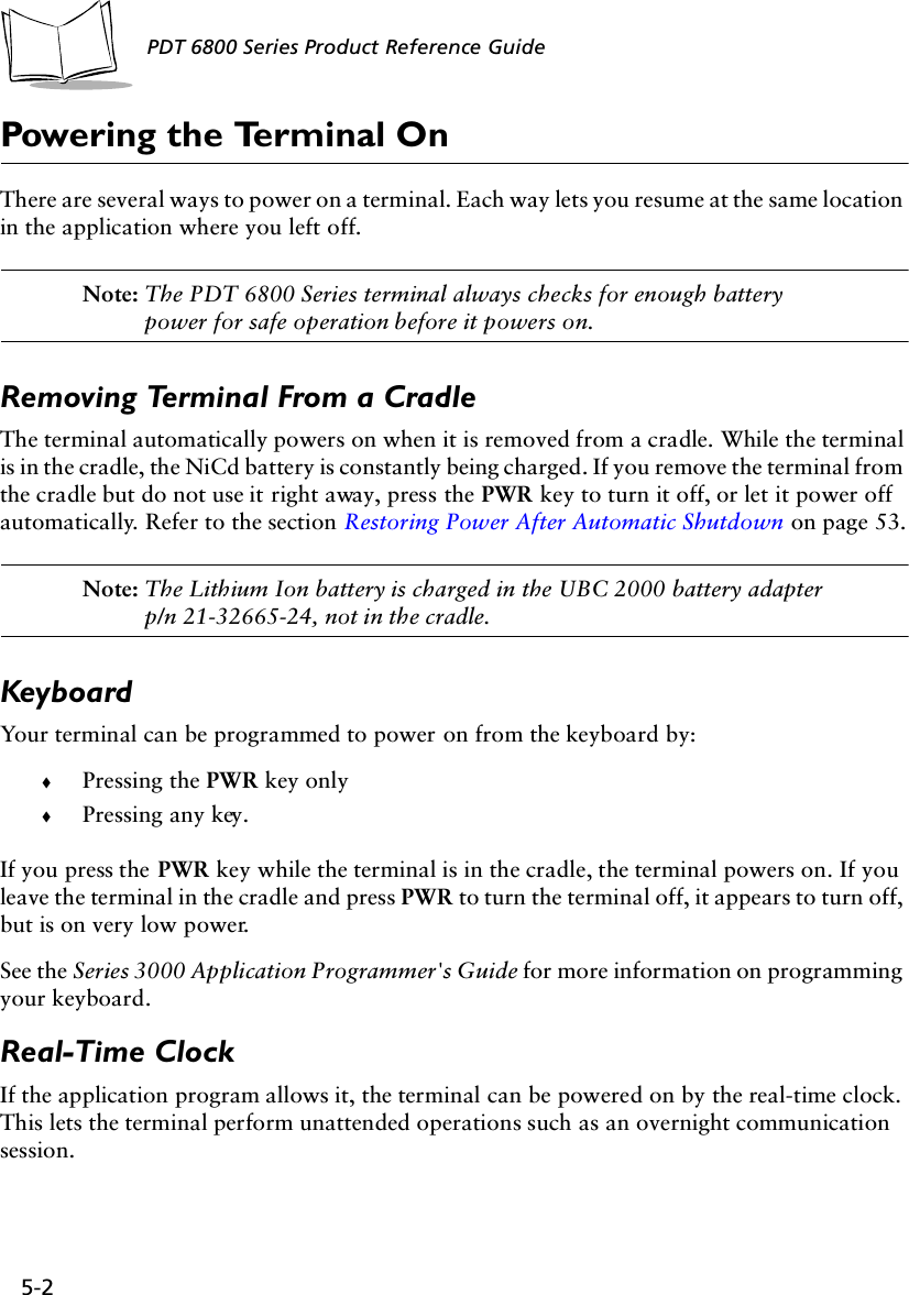
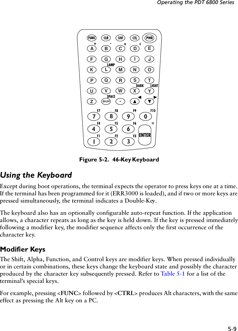
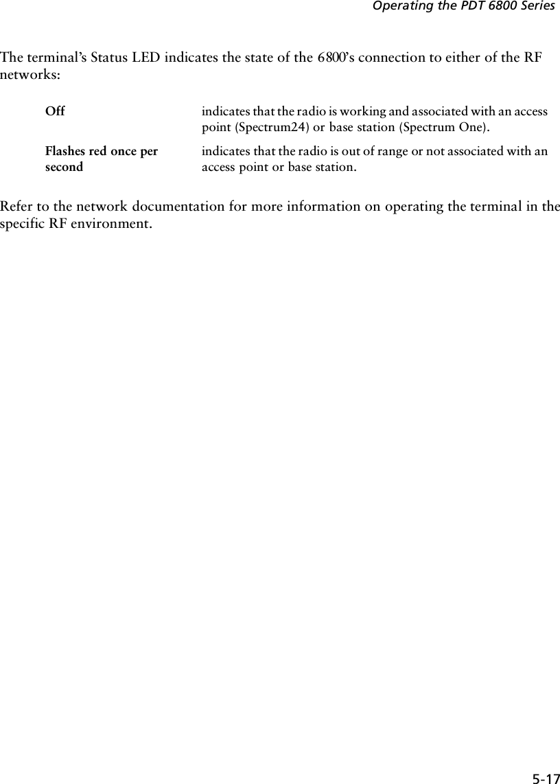
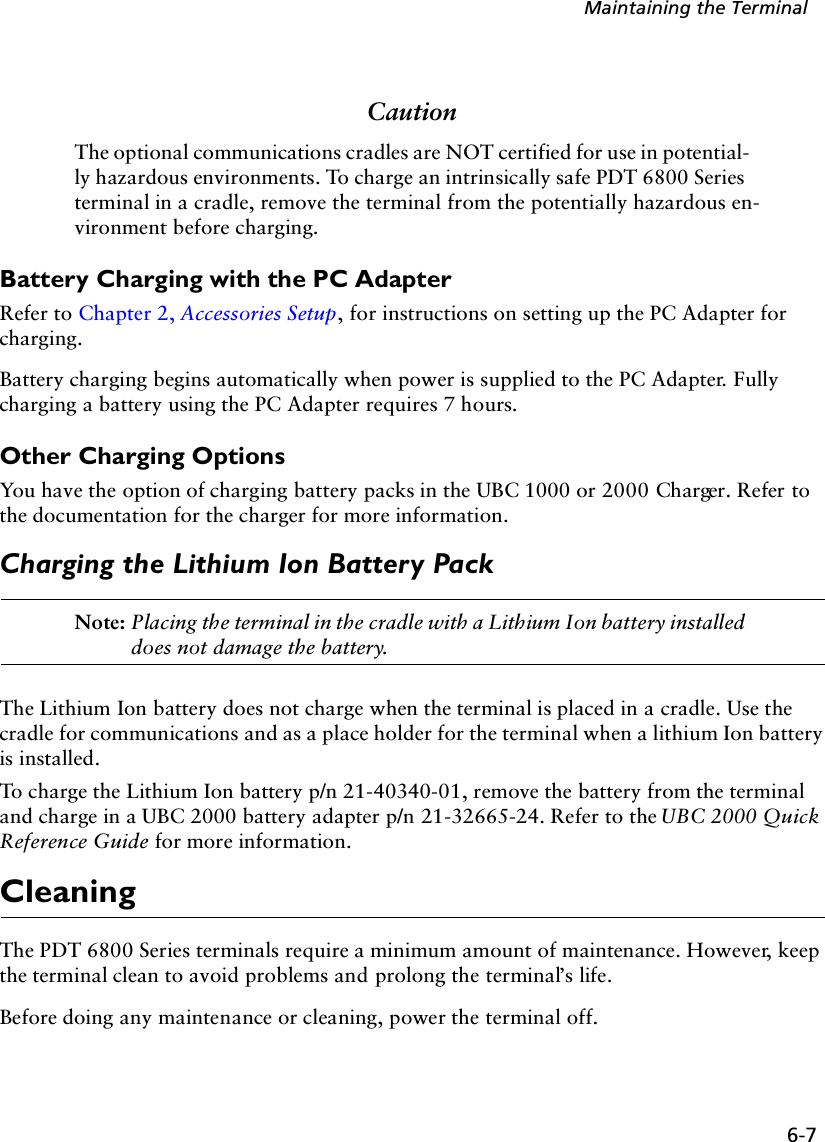
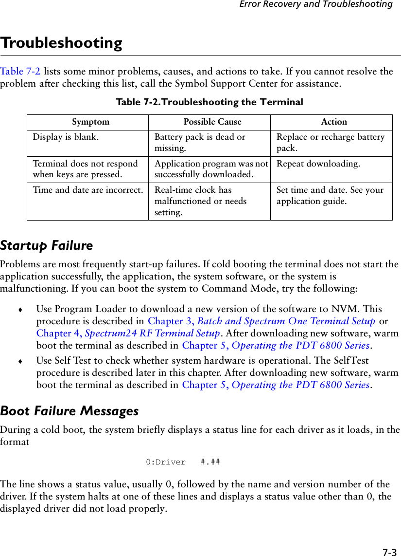
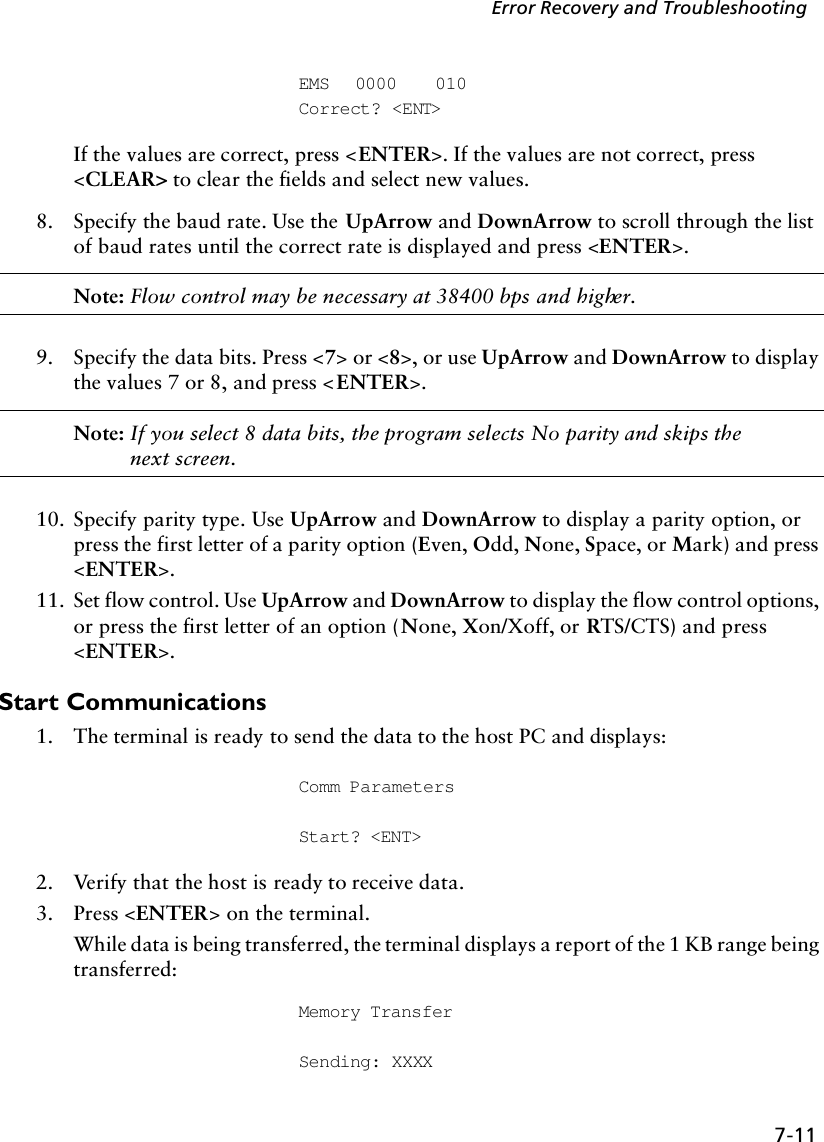
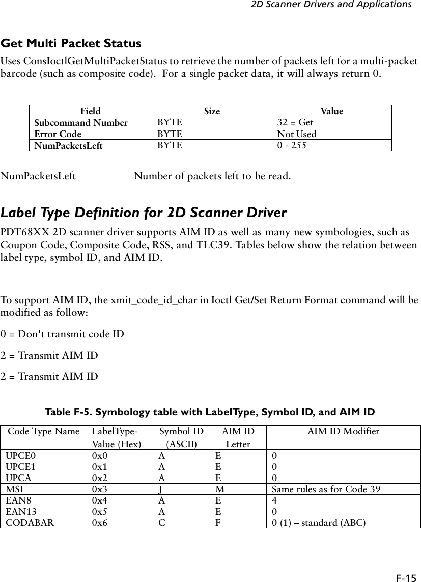
![B-6PDT 6800 Series Product Reference GuideFigure B-9. 46-Key Function Key Modified KeyboardFigure B-10. 46-Key Shift Key Modified Keyboard=*/',/\=\-[];F7 F8 F9 F10F4 F5 F6F1 F2 F3=>82&*()$%^!@#](https://usermanual.wiki/Symbol-Technologies/PDT687C.Product-Reference-Guide/User-Guide-326978-Page-95.png)
![B-7Keyboard LayoutsFigure B-11. 46-Key Control (CTL) Key Modified Keyboard=u[ ]!!](https://usermanual.wiki/Symbol-Technologies/PDT687C.Product-Reference-Guide/User-Guide-326978-Page-96.png)
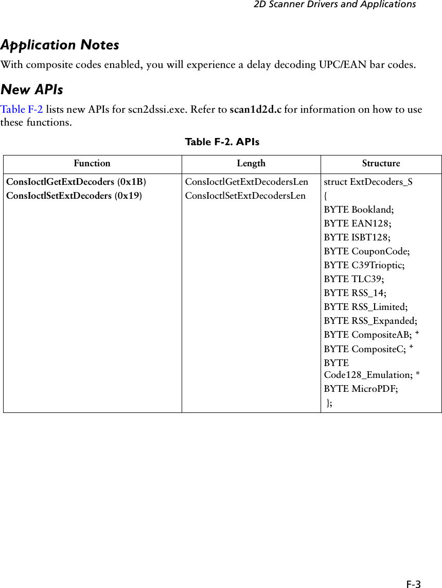
![F-52D Scanner Drivers and ApplicationsConsIoctlGetMacroPDF 0x1CConsIoctlSetMacroPDF 0x1AConsIoctlGetMacroPDFLenConsIoctlSetMacroPDFLenstruct MacroPDF_S{byte xmit_file_name;byte xmit_block_count;byte xmit_time_stamp;byte xmit_sender;byte xmit_addressee;byte xmit_csum;byte xmit_file_size;byte xmit_header;byte xmit_marker;};ConsIoctlGetMacroPDFAuxData (0x1E) ConsIoctlGetMacroPDFAuxDataLenstruct MacroPDFAuxData_S{WORD SegmentIndex;WORD SegmentCount;CHAR FileId[256];time_t Time_stamp;WORD FileSize;WORD CheckSum;CHAR FileName[256];CHAR Sender[256];CHAR Addressee[256];}; ++ConsIoctlGetVersion (0x1F) ConsIoctlGetVersionLen struct Version_S{BYTE Major;BYTE Minor;BYTE Scannerver[20];BYTE Decoderver[20];};Table F-2. APIs (Continued)Function Length Structure](https://usermanual.wiki/Symbol-Technologies/PDT687C.Product-Reference-Guide/User-Guide-326978-Page-110.png)
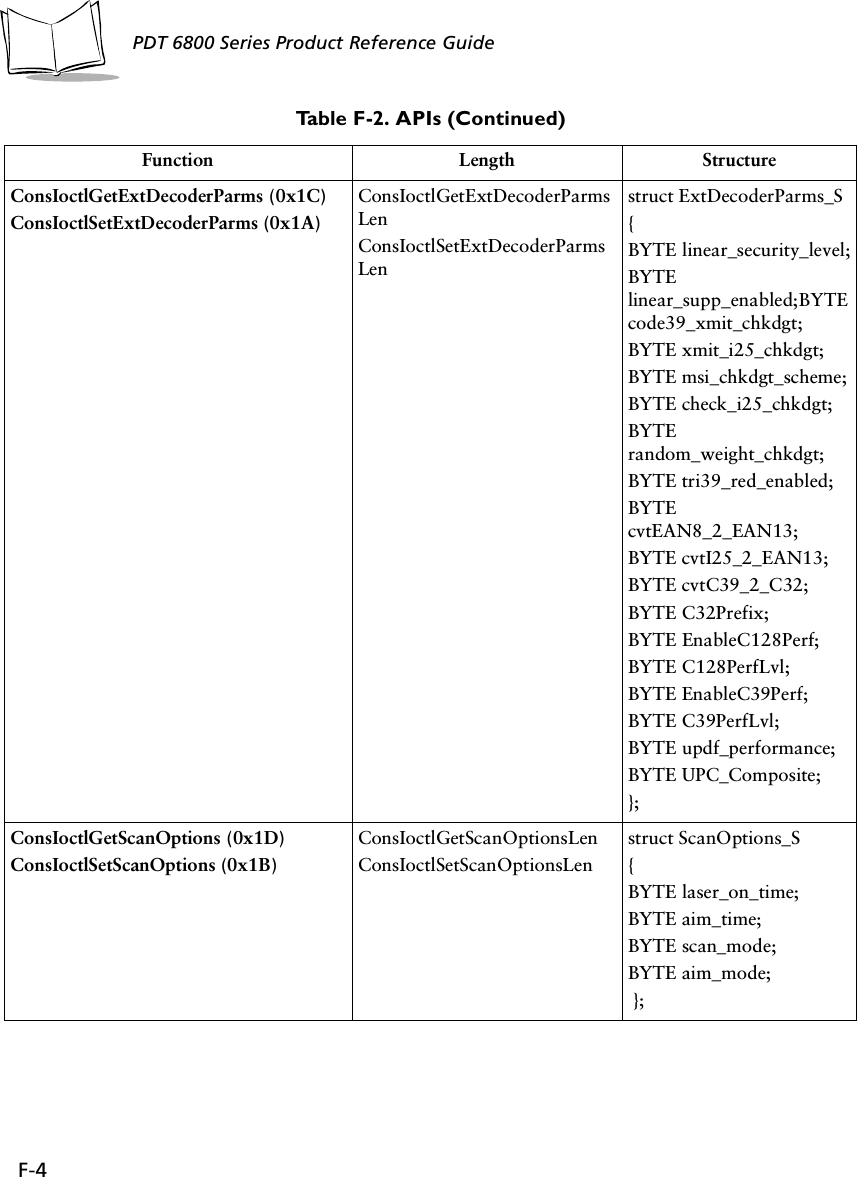
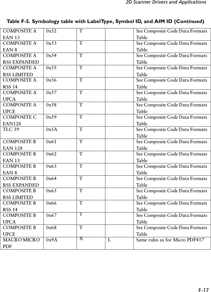
![F-16PDT 6800 Series Product Reference GuideCODE39 0x7 B A 0 – no check digit1 (3) – check digit included (exclude)D2OF5 0x8 G S 0I2OF5 0x9 F I Same rule as for Code39CODE11 0xA H H 0 (1) [2] – 1 (2) [0] check digits includedCODE93 0xB E G 0CODE128 0xC D C 0 (also see UCC/EAN-128)PDF417 0xD X L 0 – Conforms with 1994 PDF-417 spec1 – Backslash characters doubled2 – Backslash characters not dou-bledIATA2OF5 0xE G S 0EAN128 0xF K C 1 (2) – character 1 (2) is Function 1 (F1)BOOKLAND 0x11 L X 0TRIOPTIC39 0x12 M X 0COUPON 0x13 N E + C * 1POSTNET (US) 0x15 P+X0PLANET (US) 0x16 P+X0ISBT128 0x19 D C 0MICROPDF 0x1A X L 0,1 or 2 – same definition as PDF417 3 – Code128 emul: implied F1 in 1st position4 – Code 128 emul: F1 after 1st letter/digits5 – Code 128 emul: no implied F1CODE32 0x20 B A Same rules as for Code 39POSTBAR (CA) 0x26 P+X0POSTAL (UK) 0x27 P+X0MACROPDF 0x28 X L Same rules as for PDF-417RSS 14 0x30 R e 0RSS LIMITED 0x31 R e 0RSS EXPANDED 0x32 R e 0COMPOSITE A EAN 1280x51 T See Composite Code Data Formats TableTable F-5. Symbology table with LabelType, Symbol ID, and AIM ID (Continued)](https://usermanual.wiki/Symbol-Technologies/PDT687C.Product-Reference-Guide/User-Guide-326978-Page-121.png)
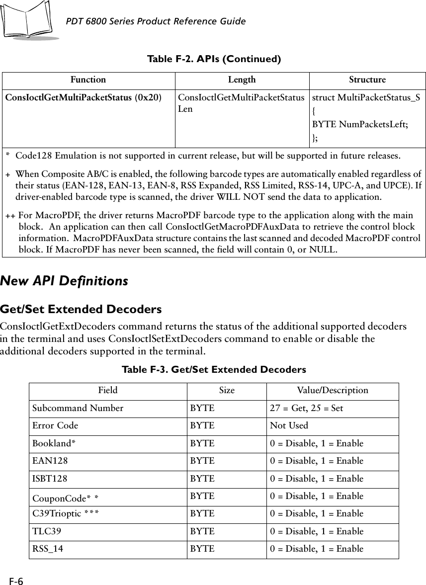
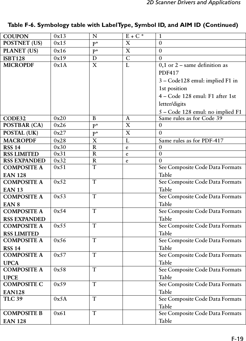
![F-18PDT 6800 Series Product Reference Guide+ For CodeID begin with ‘P’, actually it should contain three letters (such as “P01”); but forbackward compatible, only one letter will be returned.!CouponCode AIM ID: E + C denotes 2 AIM Ids are transmitted: the first prefixes the main UPC/EAN block; the second prefixes the EAN-128 block. The sample data format for CouponCode with AIM ID: ì]E0512345678902]C112345678î.All Function 1 characters in the 1D and 2D are sent as G S (29 10); the first Function 1 in the EAN-128 is not transmitted.Table F-6. Symbology table with LabelType, Symbol ID, and AIM IDCode Type Name LabelType-Val ue (Hex)Symbol ID(ASCII)AIM ID LetterAIM ID ModifierUPCE0 0x0 A E 0UPCE1 0x1 A E 0UPCA 0x2 A E 0MSI 0x3 J M Same rules as for Code 39EAN8 0x4 A E 4EAN13 0x5 A E 0CODABAR 0x6 C F 0 (1) – standard (ABC)CODE39 0x7 B A 0 – no check digit1 (3) – check digit included (exclude)D2OF5 0x8 G S 0I2OF5 0x9 F I Same rule as for Code39CODE11 0xA H H 0 (1) [2] – 1 (2) [0] check digits includedCODE93 0xB E G 0CODE128 0xC D C 0 (also see UCC/EAN-128)PDF417 0xD X L 0 – Conforms with 1994 PDF-417 spec1 – Backslash characters doubled2 – Backslash characters not dou-bledIATA2OF5 0xE G S 0EAN128 0xF K C 1 (2) – character 1 (2) is Function 1 (F1)BOOKLAND 0x11 L X 0TRIOPTIC39 0x12 M X 0Table F-5. Symbology table with LabelType, Symbol ID, and AIM ID (Continued)](https://usermanual.wiki/Symbol-Technologies/PDT687C.Product-Reference-Guide/User-Guide-326978-Page-123.png)
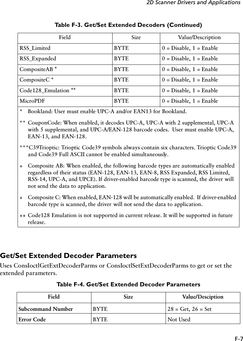
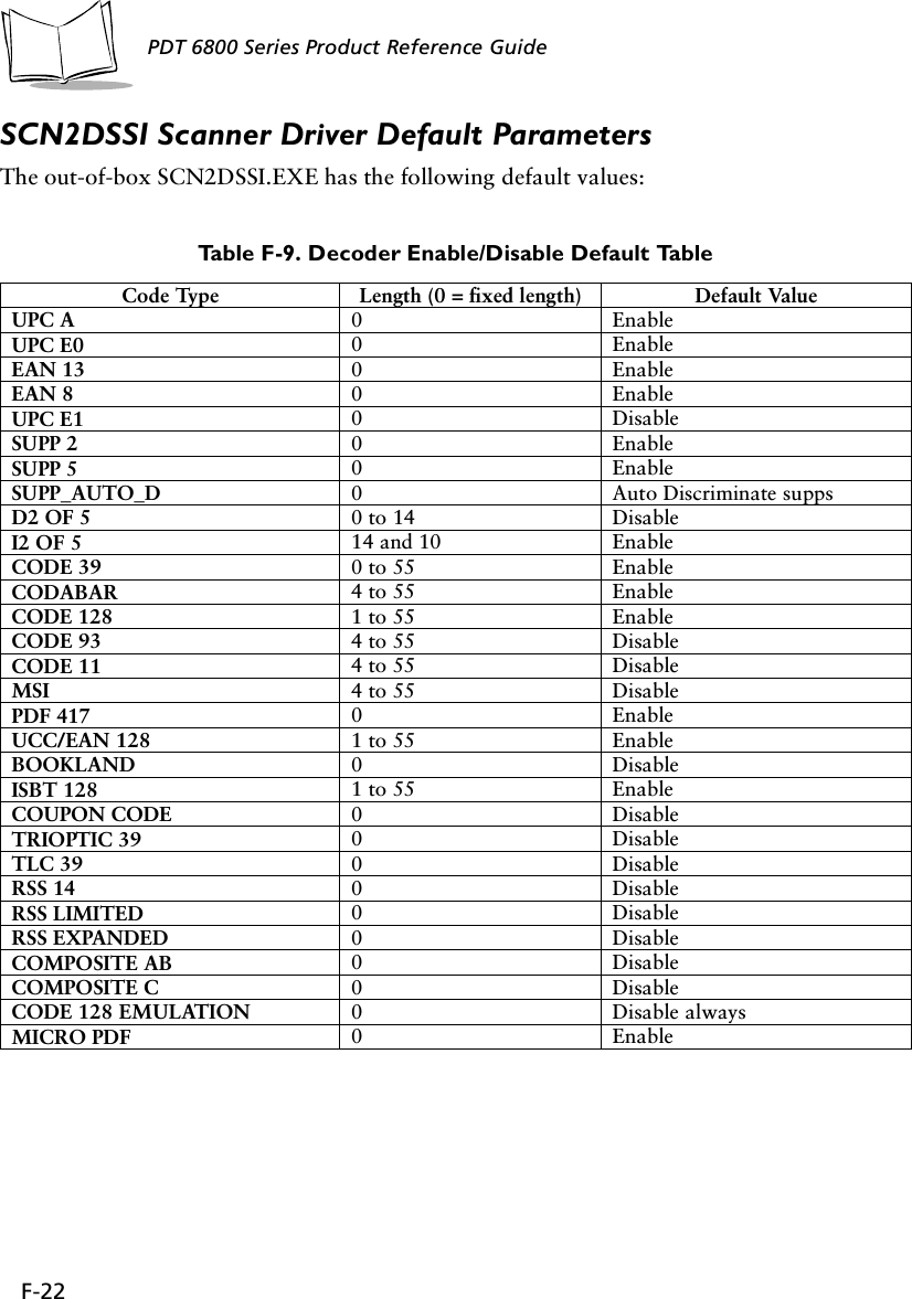
![F-20PDT 6800 Series Product Reference GuideCOMPOSITE B EAN 130x62 T See Composite Code Data Formats TableCOMPOSITE B EAN 80x63 T See Composite Code Data Formats TableCOMPOSITE B RSS EXPANDED0x64 T See Composite Code Data Formats TableCOMPOSITE B RSS LIMITED0x65 T See Composite Code Data Formats TableCOMPOSITE B RSS 140x66 T See Composite Code Data Formats TableCOMPOSITE B UPCA0x67 T See Composite Code Data Formats TableCOMPOSITE B UPCE0x68 T See Composite Code Data Formats TableMACRO MICRO PDF0x9A X L Same rules as for Micro PDF417+ For CodeID begin with ‘P’, actually it should contain three letters (such as “P01”); but for back-ward compatible, only one letter will be returned.* CouponCode AIM ID: E + C denotes 2 AIM Ids are transmitted: the first prefixes the main UPC/EAN block; the second prefixes the EAN-128 block. The sample data format for CouponCode with AIM ID: ì]E0512345678902]C112345678î.All Function 1 characters in the 1D and 2D are sent as G S (29 10); the first Function 1 in the EAN-128 is not transmitted.Table F-7. New AIM ID for UPC/EAN family with supplementalCode Type NameLabelType-Val ue (Hex)Symbol ID(ASCII)AIM ID LetterAIM ID ModifierUPCE0 + 2 0x0 A E + E 0 for main block; 1 for supplementalUPCE0 + 5 0x0 A E + E 0 for main block; 2 for supplementalUPCE1 + 2 0x01 A E + E 0 for main block; 1 for supplementalUPCE1 + 5 0x01 A E + E 0 for main block; 2 for supplementalUPCA +2 0x02 A E + E 0 for main block; 1 for supplementalUPCA + 5 0x02 A E + E 0 for main block; 2 for supplementalEAN8 + 2 0x04 A E + E 4 for main block; 1 for supplementalEAN8 + 5 0x04 A E + E 4 for main block; 2 for supplementalTable F-6. Symbology table with LabelType, Symbol ID, and AIM ID (Continued)](https://usermanual.wiki/Symbol-Technologies/PDT687C.Product-Reference-Guide/User-Guide-326978-Page-125.png)
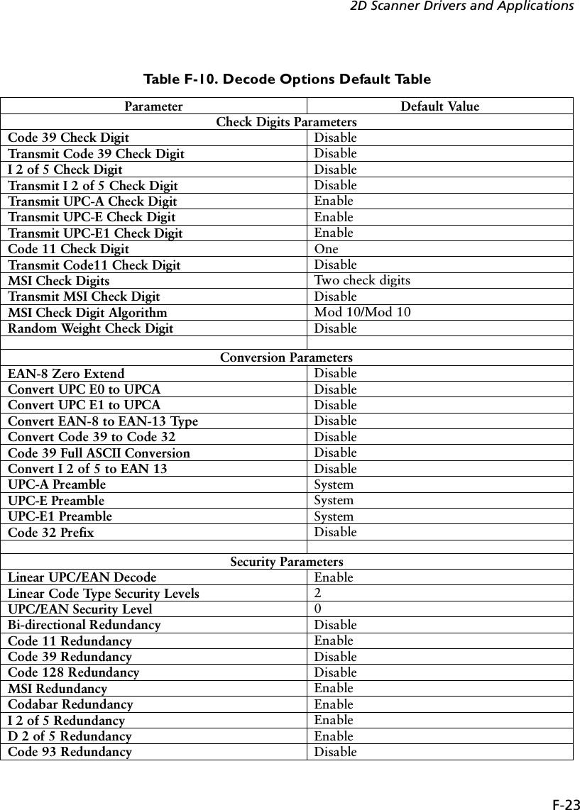
![F-212D Scanner Drivers and ApplicationsEAN13 + 2 0x05 A E + E 0 for main block; 1 for supplementalEAN13 + 5 0x05 A E + E 0 for main block; 2 for supplementalNote:E + E denotes 2 AIM Ids are transmitted: the first prefixes the main UPC/EAN block; the second prefixes the supplemental block. Sample data format: ì]E0123456]E112î.Table F-8. Composite Code Data Formats Table1D Component Data FormatStandard Mode EAN-128 Emulation ModeEAN-13, UPC-A,UPC-E1D: ]E02D: ]e0See note 1Not supportedEAN-8 1D: ]E42D: ]e0See note 1Not supportedRSS-14RSS Limited1D: ]e02D: ]e1See note 2Not supportedCode 39 (TLC39) ANSI MH10.8.3M syntax:06 Format: [)>R S 06 G S 6P 1D G S S 2D R S EOT05 Format: [)>R S 05 G S 906P 1D G S 8004 2D R S EOTSee note 3EAN-128RSS ExpandedIf the last AI in theEAN128 is a predefined,fixed length:]e0Otherwise, ]e0 GSSee note 2Not supportedNotes:1. If the UPC/EAN component has a supplemental, ]E1 precedes a 2-digit supplemental and ]E2 precedes the 5-digit supplemental 2. In standard mode, the data following symbol separator begins with AIM ID "]e1". The data fol-lowing the composite component escape mechanism begins with AIM ID "]e2" if ECI interpreta-tion is enabled, "]e3" if ECI interpretation is not enabled.3. RS is character 30 10 and EOT is character 04. The transmitted format (05 or 06) is data depen-dent.Table F-7. New AIM ID for UPC/EAN family with supplemental](https://usermanual.wiki/Symbol-Technologies/PDT687C.Product-Reference-Guide/User-Guide-326978-Page-126.png)
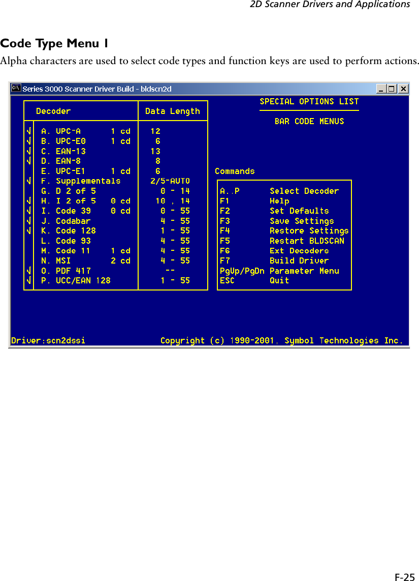
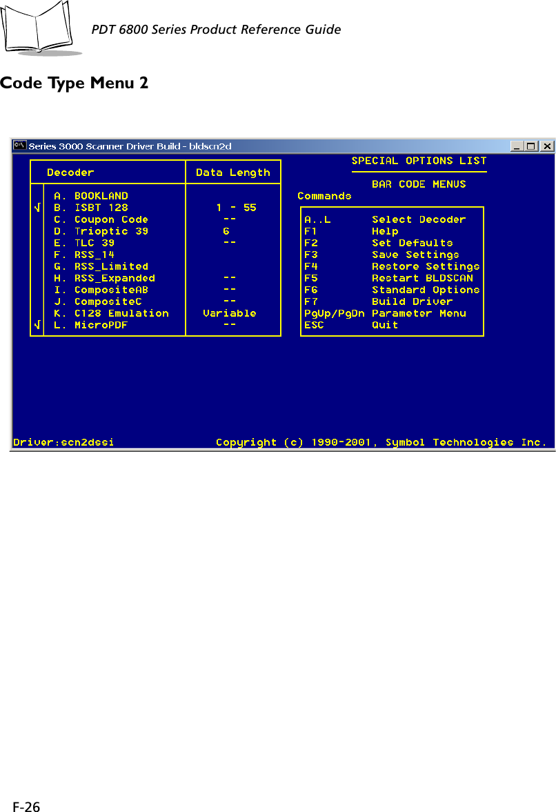
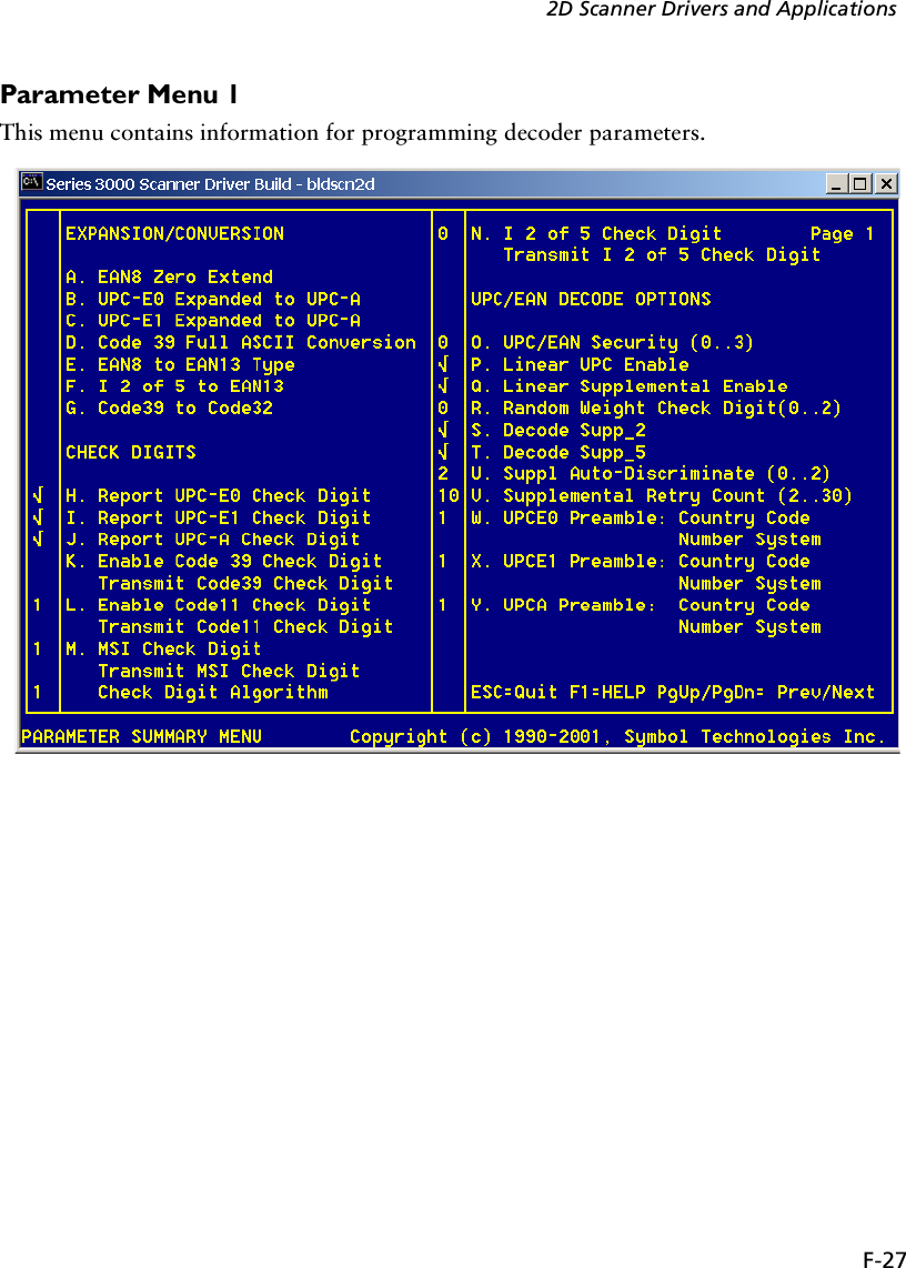
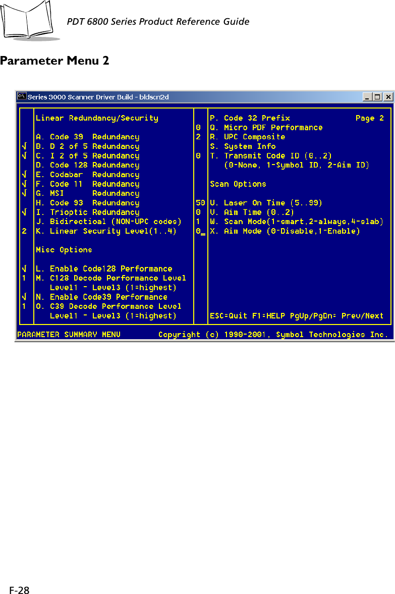
![F-24PDT 6800 Series Product Reference GuideUsing BldScn2D.exeThe Bldscn2d.exe is based on the bldscan.exe and should only be used to build SCN2DSSI.EXE. Install the PDT6800 scankit before unsing Bldscn2d.exe.Screen MenusTrioptic 39 Redundancy EnableDecode Redundancy for UPC/EAN without sup-plemental10Other ParametersCode 128 Decode Performance EnableCode 128 Decode Performance Level Level 1Code 39 Decode Performance EnableCode 39 Decode Performance Level Level 1MicroPDF Performance Level 0UPC Composite Linking Auto UPC linkageTransmit Code ID Character NoneLaser On Time 5 SecondsScanning Mode Smart RasterAim Mode Dot AimAim Time 0 Second (No Aiming)Tra n sm it “No Decode” Message DisableTable F-11. Start MenuBldScn2D Version 1.00Scn2dSSI scanner driver configuration tool.Copyright (c) 1990-2001, Symbol Technologies Inc.Usage: bldscn2d [output driver name]Hit anykey to continue...Table F-10. Decode Options Default Table (Continued)](https://usermanual.wiki/Symbol-Technologies/PDT687C.Product-Reference-Guide/User-Guide-326978-Page-129.png)