Symbol Technologies PDT687C Portable Data Terminal w/WLAN PC Module User Manual 3264502a
Symbol Technologies Inc Portable Data Terminal w/WLAN PC Module 3264502a
Contents
- 1. Product Reference Guide
- 2. Quick Reference Guide
- 3. GRG Addendum
Product Reference Guide

PDT 6800 Series
Product Reference Guide

PDT 6800 Series
Product Reference Guide
70-32645-02
Revision A
August 2001

ii
1998-2001 by Symbol Technologies, Inc. All rights reserved.
No part of this publication may be reproduced or used in any form, or by any electrical or
mechanical means, without permission in writing from Symbol. This includes electronic or
mechanical means, such as photocopying, recording, or information storage and retrieval
systems. The material in this manual is subject to change without notice.
The software is provided strictly on an “as is” basis. All software, including firmware,
furnished to the user is on a licensed basis. Symbol grants to the user a non-transferable and
non-exclusive license to use each software or firmware program delivered hereunder (licensed
program). Except as noted below, such license may not be assigned, sublicensed, or otherwise
transferred by the user without prior written consent of Symbol. No right to copy a licensed
program in whole or in part is granted, except as permitted under copyright law. The user
shall not modify, merge, or incorporate any form or portion of a licensed program with other
program material, create a derivative work from a licensed program, or use a licensed
program in a network without written permission from Symbol. The user agrees to maintain
Symbol’s copyright notice on the licensed programs delivered hereunder, and to include the
same on any authorized copies it makes, in whole or in part. The user agrees not to
decompile, disassemble, decode, or reverse engineer any licensed program delivered to the
user or any portion thereof.
Symbol reserves the right to make changes to any software or product to improve reliability,
function, or design.
Symbol does not assume any product liability arising out of, or in connection with, the
application or use of any product, circuit, or application described herein.
No license is granted, either expressly or by implication, estoppel, or otherwise under any
Symbol Technologies, Inc., intellectual property rights. An implied license only exists for
equipment, circuits, and subsystems contained in Symbol products.
Symbol, Spectrum One, and Spectrum24 are registered trademarks of Symbol Technologies,
Inc. Other product names mentioned in this manual may be trademarks or registered
trademarks of their respective companies and are hereby acknowledged.
Symbol Technologies, Inc.
One Symbol Plaza
Holtsville, New York 11742-1300
http://www.symbol.com

iii
Contents
About This Guide
Chapter Descriptions . . . . . . . . . . . . . . . . . . . . . . . . . . . . . . . . . . . . . . . . . . . . . . . . . . . . . . . . . . . . . ix
Notational Conventions . . . . . . . . . . . . . . . . . . . . . . . . . . . . . . . . . . . . . . . . . . . . . . . . . . . . . . . . . . . x
Related Publications . . . . . . . . . . . . . . . . . . . . . . . . . . . . . . . . . . . . . . . . . . . . . . . . . . . . . . . . . . . . . . x
Service Information . . . . . . . . . . . . . . . . . . . . . . . . . . . . . . . . . . . . . . . . . . . . . . . . . . . . . . . . . . . . . . xi
Symbol Support Center . . . . . . . . . . . . . . . . . . . . . . . . . . . . . . . . . . . . . . . . . . . . . . . . . . . . . . . xii
Warranty . . . . . . . . . . . . . . . . . . . . . . . . . . . . . . . . . . . . . . . . . . . . . . . . . . . . . . . . . . . . . . . . . . . . . xiv
Warranty Coverage and Procedure . . . . . . . . . . . . . . . . . . . . . . . . . . . . . . . . . . . . . . . . . . . . . . xv
General . . . . . . . . . . . . . . . . . . . . . . . . . . . . . . . . . . . . . . . . . . . . . . . . . . . . . . . . . . . . . . . . . . . xv
Chapter 1. Getting Started
Introduction . . . . . . . . . . . . . . . . . . . . . . . . . . . . . . . . . . . . . . . . . . . . . . . . . . . . . . . . . . . . . . . . . . 1-1
Parts of the PDT 6800 Series Terminal. . . . . . . . . . . . . . . . . . . . . . . . . . . . . . . . . . . . . . . . . . . . . . 1-2
Accessories . . . . . . . . . . . . . . . . . . . . . . . . . . . . . . . . . . . . . . . . . . . . . . . . . . . . . . . . . . . . . . . . . . . 1-3
Battery Chargers . . . . . . . . . . . . . . . . . . . . . . . . . . . . . . . . . . . . . . . . . . . . . . . . . . . . . . . . . . . 1-3
Printer Interface Module . . . . . . . . . . . . . . . . . . . . . . . . . . . . . . . . . . . . . . . . . . . . . . . . . . . . . 1-3
Radio and Network Options . . . . . . . . . . . . . . . . . . . . . . . . . . . . . . . . . . . . . . . . . . . . . . . . . . 1-3
Unpacking . . . . . . . . . . . . . . . . . . . . . . . . . . . . . . . . . . . . . . . . . . . . . . . . . . . . . . . . . . . . . . . . . . . 1-4
Before You Use the Terminal . . . . . . . . . . . . . . . . . . . . . . . . . . . . . . . . . . . . . . . . . . . . . . . . . . . . . 1-4
Install and Charge Battery . . . . . . . . . . . . . . . . . . . . . . . . . . . . . . . . . . . . . . . . . . . . . . . . . . . . 1-4
Load the Appropriate Software . . . . . . . . . . . . . . . . . . . . . . . . . . . . . . . . . . . . . . . . . . . . . . . . 1-4
Chapter 2. Accessories Setup
Introduction . . . . . . . . . . . . . . . . . . . . . . . . . . . . . . . . . . . . . . . . . . . . . . . . . . . . . . . . . . . . . . . . . . 2-1
Required Parts . . . . . . . . . . . . . . . . . . . . . . . . . . . . . . . . . . . . . . . . . . . . . . . . . . . . . . . . . . . . . . . . 2-2
Parts of the CRD 38/6865 . . . . . . . . . . . . . . . . . . . . . . . . . . . . . . . . . . . . . . . . . . . . . . . . . . . . . . . 2-3
Parts of the CRD 38/6866 . . . . . . . . . . . . . . . . . . . . . . . . . . . . . . . . . . . . . . . . . . . . . . . . . . . . . . . 2-3
Wall Mounting the CRD 38/6865 . . . . . . . . . . . . . . . . . . . . . . . . . . . . . . . . . . . . . . . . . . . . . . . . . 2-4
Wall Mounting the CRD 38/6866 . . . . . . . . . . . . . . . . . . . . . . . . . . . . . . . . . . . . . . . . . . . . . . . . . 2-5

iv
PDT 6800 Series Product Reference Guide
Table Mounting the CRD 38/6866 . . . . . . . . . . . . . . . . . . . . . . . . . . . . . . . . . . . . . . . . . . . . . . . . .2-5
Connecting Power . . . . . . . . . . . . . . . . . . . . . . . . . . . . . . . . . . . . . . . . . . . . . . . . . . . . . . . . . . . . . . 2-6
Connecting for Data Communications . . . . . . . . . . . . . . . . . . . . . . . . . . . . . . . . . . . . . . . . . . . 2-7
Connecting the CRD 38/6865 Internal Modem . . . . . . . . . . . . . . . . . . . . . . . . . . . . . . . . . . . . . . . . 2-9
Connecting to the Telephone Network . . . . . . . . . . . . . . . . . . . . . . . . . . . . . . . . . . . . . . . . . . . . . 2-10
Connecting the CRD 38/6866 to Other Cradles. . . . . . . . . . . . . . . . . . . . . . . . . . . . . . . . . . . 2-10
CCM 38/6860 . . . . . . . . . . . . . . . . . . . . . . . . . . . . . . . . . . . . . . . . . . . . . . . . . . . . . . . . . . . . . . . . 2-11
Parts of the CCM 38/6860 . . . . . . . . . . . . . . . . . . . . . . . . . . . . . . . . . . . . . . . . . . . . . . . . . . . 2-11
Wall Mounting. . . . . . . . . . . . . . . . . . . . . . . . . . . . . . . . . . . . . . . . . . . . . . . . . . . . . . . . . . . . 2-12
Coupling CCMs . . . . . . . . . . . . . . . . . . . . . . . . . . . . . . . . . . . . . . . . . . . . . . . . . . . . . . . . . . . 2-12
Connecting Power . . . . . . . . . . . . . . . . . . . . . . . . . . . . . . . . . . . . . . . . . . . . . . . . . . . . . . . . . 2-13
Connecting the CCM for Serial Communications . . . . . . . . . . . . . . . . . . . . . . . . . . . . . . . . . . 2-14
Daisy-Chaining Two or More CCMs . . . . . . . . . . . . . . . . . . . . . . . . . . . . . . . . . . . . . . . . . . . 2-15
PC Adapter . . . . . . . . . . . . . . . . . . . . . . . . . . . . . . . . . . . . . . . . . . . . . . . . . . . . . . . . . . . . . . . . . . 2-16
Parts of the PC Adapter . . . . . . . . . . . . . . . . . . . . . . . . . . . . . . . . . . . . . . . . . . . . . . . . . . . . .2-16
Connecting the PC Adapter to the Terminal and Serial Device. . . . . . . . . . . . . . . . . . . . . . . . 2-17
Chapter 3. Batch and Spectrum One Terminal Setup
Introduction. . . . . . . . . . . . . . . . . . . . . . . . . . . . . . . . . . . . . . . . . . . . . . . . . . . . . . . . . . . . . . . . . . . 3-1
Hardware Requirements . . . . . . . . . . . . . . . . . . . . . . . . . . . . . . . . . . . . . . . . . . . . . . . . . . . . . . . . . 3-1
Communications . . . . . . . . . . . . . . . . . . . . . . . . . . . . . . . . . . . . . . . . . . . . . . . . . . . . . . . . . . . 3-2
Downloading the Program. . . . . . . . . . . . . . . . . . . . . . . . . . . . . . . . . . . . . . . . . . . . . . . . . . . . . . . . 3-2
Initiate Host Communications Software. . . . . . . . . . . . . . . . . . . . . . . . . . . . . . . . . . . . . . . . . . 3-3
Chapter 4. Spectrum24 RF Terminal Setup
Spectrum24 Terminals . . . . . . . . . . . . . . . . . . . . . . . . . . . . . . . . . . . . . . . . . . . . . . . . . . . . . . . . . . . 4-1
Accessing the Flash Disk. . . . . . . . . . . . . . . . . . . . . . . . . . . . . . . . . . . . . . . . . . . . . . . . . . . . . . 4-1
Standard Spectrum24 Software . . . . . . . . . . . . . . . . . . . . . . . . . . . . . . . . . . . . . . . . . . . . . . . . . . . . 4-2
Chapter 5. Operating the PDT 6800 Series
Introduction. . . . . . . . . . . . . . . . . . . . . . . . . . . . . . . . . . . . . . . . . . . . . . . . . . . . . . . . . . . . . . . . . . . 5-1
Powering the Terminal On. . . . . . . . . . . . . . . . . . . . . . . . . . . . . . . . . . . . . . . . . . . . . . . . . . . . . . . . 5-2
Removing Terminal From a Cradle . . . . . . . . . . . . . . . . . . . . . . . . . . . . . . . . . . . . . . . . . . . . . 5-2
Keyboard . . . . . . . . . . . . . . . . . . . . . . . . . . . . . . . . . . . . . . . . . . . . . . . . . . . . . . . . . . . . . . . . . 5-2
Real-Time Clock. . . . . . . . . . . . . . . . . . . . . . . . . . . . . . . . . . . . . . . . . . . . . . . . . . . . . . . . . . . . 5-2
Laser Trigger . . . . . . . . . . . . . . . . . . . . . . . . . . . . . . . . . . . . . . . . . . . . . . . . . . . . . . . . . . . . . . 5-3
Restoring Power After Automatic Shutdown . . . . . . . . . . . . . . . . . . . . . . . . . . . . . . . . . . . . . . 5-3
Powering the Terminal Off . . . . . . . . . . . . . . . . . . . . . . . . . . . . . . . . . . . . . . . . . . . . . . . . . . . . . . . 5-3
Forcing Power Off . . . . . . . . . . . . . . . . . . . . . . . . . . . . . . . . . . . . . . . . . . . . . . . . . . . . . . . . . . 5-3
Restarting After a Forced Power Off . . . . . . . . . . . . . . . . . . . . . . . . . . . . . . . . . . . . . . . . . . . . 5-3
Booting the Terminal. . . . . . . . . . . . . . . . . . . . . . . . . . . . . . . . . . . . . . . . . . . . . . . . . . . . . . . . . . . . 5-4

v
Contents
Warm Boot . . . . . . . . . . . . . . . . . . . . . . . . . . . . . . . . . . . . . . . . . . . . . . . . . . . . . . . . . . . . . . . 5-4
Cold Boot . . . . . . . . . . . . . . . . . . . . . . . . . . . . . . . . . . . . . . . . . . . . . . . . . . . . . . . . . . . . . . . . 5-4
Boot to Command Mode. . . . . . . . . . . . . . . . . . . . . . . . . . . . . . . . . . . . . . . . . . . . . . . . . . . . . 5-7
Adjusting the Display . . . . . . . . . . . . . . . . . . . . . . . . . . . . . . . . . . . . . . . . . . . . . . . . . . . . . . . . . . . 5-7
Display Contrast . . . . . . . . . . . . . . . . . . . . . . . . . . . . . . . . . . . . . . . . . . . . . . . . . . . . . . . . . . . 5-7
Backlighting . . . . . . . . . . . . . . . . . . . . . . . . . . . . . . . . . . . . . . . . . . . . . . . . . . . . . . . . . . . . . . 5-7
PDT 6800 Series Keyboard. . . . . . . . . . . . . . . . . . . . . . . . . . . . . . . . . . . . . . . . . . . . . . . . . . . . . . . 5-8
Using the Keyboard . . . . . . . . . . . . . . . . . . . . . . . . . . . . . . . . . . . . . . . . . . . . . . . . . . . . . . . . . 5-9
Scanning . . . . . . . . . . . . . . . . . . . . . . . . . . . . . . . . . . . . . . . . . . . . . . . . . . . . . . . . . . . . . . . . . . . . 5-12
Scanning 1D Bar Codes . . . . . . . . . . . . . . . . . . . . . . . . . . . . . . . . . . . . . . . . . . . . . . . . . . . . . 5-12
Scanning 2D Bar Codes . . . . . . . . . . . . . . . . . . . . . . . . . . . . . . . . . . . . . . . . . . . . . . . . . . . . . 5-13
Scanning Considerations . . . . . . . . . . . . . . . . . . . . . . . . . . . . . . . . . . . . . . . . . . . . . . . . . . . . 5-14
Running Communications . . . . . . . . . . . . . . . . . . . . . . . . . . . . . . . . . . . . . . . . . . . . . . . . . . . . . . 5-16
Communicating With a Host. . . . . . . . . . . . . . . . . . . . . . . . . . . . . . . . . . . . . . . . . . . . . . . . . 5-16
Communicating With a Printer . . . . . . . . . . . . . . . . . . . . . . . . . . . . . . . . . . . . . . . . . . . . . . . 5-16
Radio Communications. . . . . . . . . . . . . . . . . . . . . . . . . . . . . . . . . . . . . . . . . . . . . . . . . . . . . 5-16
Chapter 6. Maintaining the Terminal
Batteries . . . . . . . . . . . . . . . . . . . . . . . . . . . . . . . . . . . . . . . . . . . . . . . . . . . . . . . . . . . . . . . . . . . . . 6-1
Battery Life . . . . . . . . . . . . . . . . . . . . . . . . . . . . . . . . . . . . . . . . . . . . . . . . . . . . . . . . . . . . . . . 6-2
When to Replace or Recharge the Battery . . . . . . . . . . . . . . . . . . . . . . . . . . . . . . . . . . . . . . . . 6-2
Replacing the Battery Pack . . . . . . . . . . . . . . . . . . . . . . . . . . . . . . . . . . . . . . . . . . . . . . . . . . . . . . . 6-3
Removing the Battery Pack . . . . . . . . . . . . . . . . . . . . . . . . . . . . . . . . . . . . . . . . . . . . . . . . . . . 6-3
Installing the Battery Pack. . . . . . . . . . . . . . . . . . . . . . . . . . . . . . . . . . . . . . . . . . . . . . . . . . . . 6-4
Battery Charging Tips . . . . . . . . . . . . . . . . . . . . . . . . . . . . . . . . . . . . . . . . . . . . . . . . . . . . . . . 6-5
Charging the NiCd Battery Pack . . . . . . . . . . . . . . . . . . . . . . . . . . . . . . . . . . . . . . . . . . . . . . . 6-6
Charging the Lithium Ion Battery Pack . . . . . . . . . . . . . . . . . . . . . . . . . . . . . . . . . . . . . . . . . . 6-7
Cleaning . . . . . . . . . . . . . . . . . . . . . . . . . . . . . . . . . . . . . . . . . . . . . . . . . . . . . . . . . . . . . . . . . . . . . 6-7
Storage . . . . . . . . . . . . . . . . . . . . . . . . . . . . . . . . . . . . . . . . . . . . . . . . . . . . . . . . . . . . . . . . . . 6-8
Chapter 7. Error Recovery and Troubleshooting
Introduction . . . . . . . . . . . . . . . . . . . . . . . . . . . . . . . . . . . . . . . . . . . . . . . . . . . . . . . . . . . . . . . . . . 7-1
Error Messages . . . . . . . . . . . . . . . . . . . . . . . . . . . . . . . . . . . . . . . . . . . . . . . . . . . . . . . . . . . . . . . . 7-2
Troubleshooting . . . . . . . . . . . . . . . . . . . . . . . . . . . . . . . . . . . . . . . . . . . . . . . . . . . . . . . . . . . . . . . 7-3
Startup Failure . . . . . . . . . . . . . . . . . . . . . . . . . . . . . . . . . . . . . . . . . . . . . . . . . . . . . . . . . . . . 7-3
Boot Failure Messages. . . . . . . . . . . . . . . . . . . . . . . . . . . . . . . . . . . . . . . . . . . . . . . . . . . . . . . 7-3
Spectrum24 Terminal . . . . . . . . . . . . . . . . . . . . . . . . . . . . . . . . . . . . . . . . . . . . . . . . . . . . . . . 7-4
Self Test Function . . . . . . . . . . . . . . . . . . . . . . . . . . . . . . . . . . . . . . . . . . . . . . . . . . . . . . . . . . . . . . 7-5
Running Self Test . . . . . . . . . . . . . . . . . . . . . . . . . . . . . . . . . . . . . . . . . . . . . . . . . . . . . . . . . . 7-5
Self Test Summaries. . . . . . . . . . . . . . . . . . . . . . . . . . . . . . . . . . . . . . . . . . . . . . . . . . . . . . . . . 7-6
Keyboard Test . . . . . . . . . . . . . . . . . . . . . . . . . . . . . . . . . . . . . . . . . . . . . . . . . . . . . . . . . . . . . 7-6
Memory Transfer Program . . . . . . . . . . . . . . . . . . . . . . . . . . . . . . . . . . . . . . . . . . . . . . . . . . . . . . . 7-8

vi
PDT 6800 Series Product Reference Guide
Hardware Setup . . . . . . . . . . . . . . . . . . . . . . . . . . . . . . . . . . . . . . . . . . . . . . . . . . . . . . . . . . . . 7-8
Set Communications Parameters. . . . . . . . . . . . . . . . . . . . . . . . . . . . . . . . . . . . . . . . . . . . . . . . 7-9
Internal Modem Problems . . . . . . . . . . . . . . . . . . . . . . . . . . . . . . . . . . . . . . . . . . . . . . . . . . . . . . . 7-12
Scanning Problems. . . . . . . . . . . . . . . . . . . . . . . . . . . . . . . . . . . . . . . . . . . . . . . . . . . . . . . . . . . . . 7-12
What If... . . . . . . . . . . . . . . . . . . . . . . . . . . . . . . . . . . . . . . . . . . . . . . . . . . . . . . . . . . . . . . . . 7-12
Appendix A. Null Modem Pin-outs
Null Modem Pin-Outs for Full Duplex . . . . . . . . . . . . . . . . . . . . . . . . . . . . . . . . . . . . . . . . . . . . . . A-1
Null Modem Pin-outs for Half-Duplex . . . . . . . . . . . . . . . . . . . . . . . . . . . . . . . . . . . . . . . . . . . . . . A-2
Appendix B. Keyboard Layouts
Introduction. . . . . . . . . . . . . . . . . . . . . . . . . . . . . . . . . . . . . . . . . . . . . . . . . . . . . . . . . . . . . . . . . . .B-1
35-Key Keyboard. . . . . . . . . . . . . . . . . . . . . . . . . . . . . . . . . . . . . . . . . . . . . . . . . . . . . . . . . . . . . . . B-2
46-Key Keyboard. . . . . . . . . . . . . . . . . . . . . . . . . . . . . . . . . . . . . . . . . . . . . . . . . . . . . . . . . . . . . . . B-5
Appendix C. Communications Status Codes
Introduction. . . . . . . . . . . . . . . . . . . . . . . . . . . . . . . . . . . . . . . . . . . . . . . . . . . . . . . . . . . . . . . . . . .C-1
Appendix D. Specifications
Environment . . . . . . . . . . . . . . . . . . . . . . . . . . . . . . . . . . . . . . . . . . . . . . . . . . . . . . . . . . . . . . . . . D-1
RF Communications . . . . . . . . . . . . . . . . . . . . . . . . . . . . . . . . . . . . . . . . . . . . . . . . . . . . . . . . . . . D-2
Scanning Decode Zones . . . . . . . . . . . . . . . . . . . . . . . . . . . . . . . . . . . . . . . . . . . . . . . . . . . . . . . . . D-3
Appendix E. Boot-Up Quick Reference
Introduction. . . . . . . . . . . . . . . . . . . . . . . . . . . . . . . . . . . . . . . . . . . . . . . . . . . . . . . . . . . . . . . . . . .E-1

vii
Contents
Appendix F. 2D Scanner Drivers and Applications
Introduction . . . . . . . . . . . . . . . . . . . . . . . . . . . . . . . . . . . . . . . . . . . . . . . . . . . . . . . . . . . . . . . . . . F-1
Using Scn2dssi.exe . . . . . . . . . . . . . . . . . . . . . . . . . . . . . . . . . . . . . . . . . . . . . . . . . . . . . . . . . . . . . F-1
Usage . . . . . . . . . . . . . . . . . . . . . . . . . . . . . . . . . . . . . . . . . . . . . . . . . . . . . . . . . . . . . . . . . . . F-1
Output Messages. . . . . . . . . . . . . . . . . . . . . . . . . . . . . . . . . . . . . . . . . . . . . . . . . . . . . . . . . . . F-2
Application Development . . . . . . . . . . . . . . . . . . . . . . . . . . . . . . . . . . . . . . . . . . . . . . . . . . . . F-2
New APIs . . . . . . . . . . . . . . . . . . . . . . . . . . . . . . . . . . . . . . . . . . . . . . . . . . . . . . . . . . . . . . . . F-3
Using Bldscan.exe . . . . . . . . . . . . . . . . . . . . . . . . . . . . . . . . . . . . . . . . . . . . . . . . . . . . . . . . . . . . . . F-5
Screen Menus . . . . . . . . . . . . . . . . . . . . . . . . . . . . . . . . . . . . . . . . . . . . . . . . . . . . . . . . . . . . . F-6
Index
Feedback

viii
PDT 6800 Series Product Reference Guide

ix
About This Guide
The PDT 6800 Series Product Reference Guide provides general instructions for setup,
initializing, operating, troubleshooting, and maintaining the PDT 6800 Series terminal.
Chapter Descriptions
Following are brief descriptions of each chapter in this guide.
!Chapter 1, Getting Started provides a product overview and information on terminal
parts, operation, accessories, batteries, and loading software.
!Chapter 2, Accessories Setup general information on the CCM 38/6860, CRD 38/
6865, CRD 38/6866, and PC adapter.
!Chapter 3, Batch and Spectrum One Terminal Setup provides information on batch
and Spectrum One hardware requirements and loading programs.
!Chapter 4, Spectrum24 RF Terminal Setup provides general information on
Spectrum24 software, initialization, and options.
!Chapter 5, Operating the PDT 6800 Series describes how to use the terminal.
!Chapter 6, Maintaining the Terminal includes tips on properly maintaining your
terminal and batteries.
!Chapter 7, Error Recovery and Troubleshooting basic information on terminal and
software troubleshooting.
!Appendix A, Null Modem Pin-outs provides the pin-outs for null modem
communication.
!Appendix B, Keyboard Layouts describes the 35-key and 46-key keyboards and the
associated key functions.
!Appendix C, Communications Status Codes provides communication status codes
and their meaning.

x
PDT 6800 Series Product Reference Guide
!Appendix D, Specifications provides the technical specifications for the terminal.
!Appendix E, Boot-Up Quick Reference provides the key sequence necessary to
initiate a warm boot, cold boot, or command mode start.
!Appendix F, 2D Scanner Drivers and Applications describes the installation of the
2D scan engine drivers and applications.
Notational Conventions
The following conventions are used in this document:
• Italics are used to highlight specific items in the general text, and to identify
chapters and sections in this and related documents.
• Bullets (•) indicate:
• action items
• lists of alternatives
• lists of required steps that are not necessarily sequential
!Sequential lists (e.g., those that describe step-by-step procedures) appear as
numbered lists.
Related Publications
The following is a list of documents and publications that you may find useful if you want to
know more about the PDT 6800 Series terminals or about the tools and utilities that are
available for writing applications for the terminals.
!PDT 6800 Series Quick Reference Guide
p/n 70-32644-XX
!CCM 38/6860 Quick Reference Guide
p/n 70-33400-XX
!CRD 38/6865 Quick Reference Guide
p/n 70-33401-XX
!CRD 38/6866 Quick Reference Guide
p/n 70-33402-XX
!Printer Interface Module Quick Reference Guide
p/n 59164-00-82
!Series 3000 Application Programmer's Guide
p/n 70-16308-XX

xi
About This Guide
!Series 3000 Application Programmer’s Reference Manual
p/n 70-16309-XX
!Series 3000 System Software Manual
p/n 70-16310-XX
!Series 3000 Application Developer’s Library
p/n 70-16311-XX
!Spectrum24 Access Point User’s Guide
p/n 70-12057-XX
!Spectrum24 Network Terminal Technical Reference Guide
p/n 70-20193-XX
!Novell LAN Workplace Reference Manual
p/n 70-20288-XX
!Spectrum24 TNClient System Administrator’s Guide
p/n 70-20244-XX
!Spectrum24 STEP Installation and Configuration Guide for Series 3000 Flash Disk
Ter minals
p/n 70-20343-XX
!Spectrum24 NDK Series 3000
p/n 70-20481-XX
Service Information
If you have a problem with your equipment, contact the Symbol Support Center for your
region. See page xii for contact information. Before calling, have the model number, serial
number, and several of your bar code symbols at hand.
Call the Support Center from a phone near the scanning equipment so that the service person
can try to talk you through your problem. If the equipment is found to be working properly
and the problem is symbol readability, the Support Center will request samples of your bar
codes for analysis at our plant.
If your problem cannot be solved over the phone, you may need to return your equipment for
servicing. If that is necessary, you will be given specific directions.
Note: Symbol Technologies is not responsible for any damages incurred
during shipment if the approved shipping container is not used.
Shipping the units improperly can possibly void the warranty. If the

xii
PDT 6800 Series Product Reference Guide
original shipping container was not kept, contact Symbol to have
another sent to you.
Symbol Support Center
For service information, warranty information or technical assistance contact or call the
Symbol Support Center in:
United States
Symbol Technologies, Inc.
One Symbol Plaza
Holtsville, New York 11742-1300
1-800-653-5350
Canada
Symbol Technologies Canada, Inc.
2540 Matheson Boulevard East
Mississauga, Ontario, Canada L4W 4Z2
905-629-7226
United Kingdom
Symbol Technologies
Symbol Place
Winnersh Triangle, Berkshire RG41 5TP
United Kingdom
0800 328 2424 (Inside UK)
+44 208 945 7529 (Outside UK)
Asia/Pacific
Symbol Technologies Asia, Inc.
230 Victoria Street #04-05
Bugis Junction Office Tower
Singapore 188024
337-6588 (Inside Singapore)
+65-337-6588 (Outside Singapore)
Australia
Symbol Technologies Pty. Ltd.
432 St. Kilda Road
Melbourne, Victoria 3004
1-800-672-906 (Inside Australia)
+61-3-9866-6044 (Outside Australia)
Austria
Symbol Technologies Austria GmbH
Prinz-Eugen Strasse 70
Suite 3
2.Haus, 5.Stock
1040 Vienna, Austria
1-505-5794 (Inside Austria)
+43-1-505-5794 (Outside Austria)
Denmark
Symbol Technologies AS
Gydevang 2,
DK-3450 Allerod, Denmark
7020-1718 (Inside Denmark)
+45-7020-1718 (Outside Denmark)
Europe/Mid-East Distributor Operations
Contact your local distributor or call
+44 118 945 7360

xiii
About This Guide
Finland
Oy Symbol Technologies
Kaupintie 8 A 6
FIN-00440 Helsinki, Finland
9 5407 580 (Inside Finland)
+358 9 5407 580 (Outside Finland)
France
Symbol Technologies France
Centre d'Affaire d'Antony
3 Rue de la Renaissance
92184 Antony Cedex, France
01-40-96-52-21 (Inside France)
+33-1-40-96-52-50 (Outside France)
Germany
Symbol Technologies GmbH
Waldstrasse 68
D-63128 Dietzenbach, Germany
6074-49020 (Inside Germany)
+49-6074-49020 (Outside Germany)
Italy
Symbol Technologies Italia S.R.L.
Via Cristoforo Columbo, 49
20090 Trezzano S/N Navigilo
Milano, Italy
2-484441 (Inside Italy)
+39-02-484441 (Outside Italy)
Latin America Sales Support
7900 Glades Road
Suite 340
Boca Raton, Florida 33434 USA
1-800-347-0178 (Inside United States)
+1-561-483-1275 (Outside United States)
Mexico
Symbol Technologies Mexico Ltd.
Torre Picasso
Boulevard Manuel Avila Camacho No 88
Lomas de Chapultepec CP 11000
Mexico City, DF, Mexico
5-520-1835 (Inside Mexico)
+52-5-520-1835 (Outside Mexico)
Netherlands
Symbol Technologies
Kerkplein 2, 7051 CX
Postbus 24 7050 AA
Varsseveld, Netherlands
315-271700 (Inside Netherlands)
+31-315-271700 (Outside Netherlands)
Norway
Symbol Technologies
Trollasveien 36
Postboks 72
1414 Trollasen, Norway
66810600 (Inside Norway)
+47-66810600 (Outside Norway)

xiv
PDT 6800 Series Product Reference Guide
If you purchased your Symbol product from a Symbol Business Partner, contact that Business
Partner for service.
Warranty
Symbol Technologies, Inc. (“Symbol”) manufactures its hardware products in accordance with
industry-standard practices. Symbol warrants that for a period of twelve (12) months from date of
shipment, products will be free from defects in materials and workmanship.
This warranty is provided to the original owner only and is not transferable to any third party. It shall
not apply to any product (i) which has been repaired or altered unless done or approved by Symbol, (ii)
which has not been maintained in accordance with any operating or handling instructions supplied by
Symbol, (iii) which has been subjected to unusual physical or electrical stress, misuse, abuse, power
shortage, negligence or accident or (iv) which has been used other than in accordance with the product
operating and handling instructions. Preventive maintenance is the responsibility of customer and is not
covered under this warranty.
Wear items and accessories having a Symbol serial number, will carry a 90-day limited warranty. Non-
serialized items will carry a 30-day limited warranty.
South Africa
Symbol Technologies Africa Inc.
Block B2
Rutherford Estate
1 Scott Street
Waverly 2090 Johannesburg
Republic of South Africa
11-4405668 (Inside South Africa)
+27-11-4405668 (Outside South Africa)
Spain
Symbol Technologies S.A.
Edificioi la Piovera Azul
C. Peonias, No. 2 - Sexta Planta
28042 Madrid, Spain
+913244000 (Inside Spain)
+34-9-1-320-39-09 (Outside Spain)
Sweden
Symbol Technologies AB
Albygatan 109D
Solna
Sweden
84452900 (Inside Sweden)
+46 84452900 (Outside Sweden)

xv
About This Guide
Warranty Coverage and Procedure
During the warranty period, Symbol will repair or replace defective products returned to Symbol’s
manufacturing plant in the US. For warranty service in North America, call the Symbol Support Center
at 1-800-653-5350. International customers should contact the local Symbol office or support center.
If warranty service is required, Symbol will issue a Return Material Authorization Number. Products
must be shipped in the original or comparable packaging, shipping and insurance charges prepaid.
Symbol will ship the repaired or replacement product freight and insurance prepaid in North America.
Shipments from the US or other locations will be made F.O.B. Symbol’s manufacturing plant.
Symbol will use new or refurbished parts at its discretion and will own all parts removed from repaired
products. Customer will pay for the replacement product in case it does not return the replaced product
to Symbol within 3 days of receipt of the replacement product. The process for return and customer’s
charges will be in accordance with Symbol’s Exchange Policy in effect at the time of the exchange.
Customer accepts full responsibility for its software and data including the appropriate backup thereof.
Repair or replacement of a product during warranty will not extend the original warranty term.
Symbol’s Customer Service organization offers an array of service plans, such as on-site, depot, or phone
support, that can be implemented to meet customer’s special operational requirements and are available
at a substantial discount during warranty period.
General
Except for the warranties stated above, Symbol disclaims all warranties, express or implied, on products
furnished hereunder, including without limitation implied warranties of merchantability and fitness for
a particular purpose. The stated express warranties are in lieu of all obligations or liabilities on part of
Symbol for damages, including without limitation, special, indirect, or consequential damages arising
out of or in connection with the use or performance of the product.
Seller’s liability for damages to buyer or others resulting from the use of any product, shall in no way
exceed the purchase price of said product, except in instances of injury to persons or property.
Some states (or jurisdictions) do not allow the exclusion or limitation of incidental or consequential
damages, so the proceeding exclusion or limitation may not apply to you.

xvi
PDT 6800 Series Product Reference Guide

1-1
Chapter 1
Getting Started
Introduction
The PDT 6800 Series terminal is a hand-held, battery-powered, portable data collection
device. Data is entered from the terminal’s keyboard or through the integrated laser scanner.
As a remote terminal, it collects and stores data that is later uploaded to a host computer. The
PDT 6800 Series terminals include:
!PDT 6800 - batch terminal (no radio)
!PDT 6810 - Spectrum One® network
!PDT 6842 - 2 Mb Spectrum24® radio network
!PDT 6845 - 2 Mb Spectrum24® radio (short range) network
!PDT 6846 - 11 Mb Spectrum24® radio network
Since the procedures and descriptions in this guide are similar for all terminals listed above,
PDT 6800 Series terminals is used as a general term describing all terminals, unless otherwise
specified.
PDT 6800 Series terminals use Caldera’s DR DOS™ operating system that is compatible with
and extends Microsoft® MS-DOS®. Although the terminals are MS-DOS feature compatible,
they are not one hundred percent MS-DOS compatible. DR DOS provides access to a number
of commercially available programming tools. Additional programming tools are available
from Symbol for easier programming and access to special features.
1-2
PDT 6800 Series Product Reference Guide
Power saving features of the PDT 6800 Series terminals include auto-off and power save
modes, which reduce power consumption until an operator provides input. These features
conserve battery power, lengthening the time between charges or replacement.
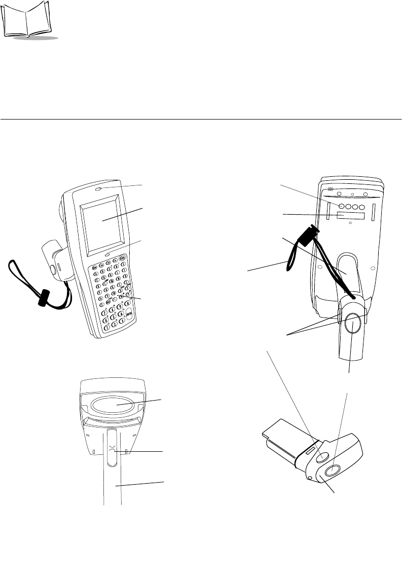
Parts of the PDT 6800 Series Terminal
Figure 1-1. Parts of the PDT 6800 Series Terminal
+
-
=
Status
-
Keyboa rd
Display
Battery
Recharge
Contacts
Wrist Strap
Battery Compartment
Battery
Release
Button
Scan LED
Battery
Lock
Scan Window
Trigger
Handle
(Battery
Compartment)
Optical
Connectors
Status LED
Battery Pack

1-3
Getting Started
Accessories
The following accessories are available for the PDT 6800 Series terminal.
Battery Chargers
The terminal uses a six-cell 600 mAh (intrinsically safe) Nickel Cadmium (NiCd) battery, or
a Lithium Ion battery.
The NiCd battery is charged using one of the following charging accessories:
!CCM 38/6860 — Four-slot Charging and Communications Module (CCM) for
charging NiCd battery packs in the terminal and spare battery packs; also performs
communications between terminals and a host, modem, or printer.
!CRD 38/6865 — Single-slot cradle for charging NiCd battery packs; also performs
communications between terminals and a host, a modem, or a printer.
!CRD 38/6866 — Four-slot cradle for charging NiCd battery packs in the terminal
and for communicating between terminals and a host, a modem, or a printer.
!UBC Charger — UBC 1000 or 2000 battery charger.
!PC Adapter — Works with the Printer Interface Module (PIM) to communicate with
the host PC without a cradle or to charge a NiCd battery pack in the terminal
without a cradle.
The Lithium Ion battery is charged using the UBC 2000 charging adapter p/n 21-32665-24.
Printer Interface Module
The Printer Interface Module works with the PC Adapter to perform communications
between the terminal and a host PC or a printer without a cradle.
Radio and Network Options
Spectrum One Network
The PDT 6810 includes an internal radio frequency transmitter/receiver for use in a Symbol
Spectrum One network.
Spectrum24 Network
The PDT 6842, PDT 6845, and PDT 6846 include an internal radio frequency transmitter/
receiver for use in a Symbol Spectrum24 network. Refer to Spectrum24 Network Terminal
Technical Reference Guide, p/n 70-20193-XX, for more information.

1-4
PDT 6800 Series Product Reference Guide
Unpacking
Remove the clear protective tape from the display and the optical connector.
Save the shipping container for later storage or shipping. Inspect all equipment for damage
and make sure you have received everything listed on the packing slip.
If you find anything unsatisfactory or missing, contact your authorized customer support
representative immediately.
Before You Use the Terminal
Install and Charge Battery
Prior to using the PDT 6800 Series terminal for the first time, install the battery pack. Be sure
to charge the battery pack before use. Refer to Chapter 6, Maintaining the Terminal.
If you hear a repeated tone or see a message on the display, recharge or replace the battery
pack. Refer to Chapter 6, Maintaining the Terminal.
Load the Appropriate Software
What software you load and how you load it depends on the environment in which you use it:
!If the terminal is intended for use in batch applications (PDT 6800) or in a Spectrum
One network environment (PDT 6810), refer to Chapter 3, Batch and Spectrum One
Terminal Setup for information on loading the software.
!If the terminal is intended for use in a Spectrum24 network environment (PDT 6842,
PDT 6845, or PDT 6846), refer to Chapter 4, Spectrum24 RF Terminal Setup for
information on loading the software.
!If you are using the 2D scan engine, install the appropriate drivers and applications.
Refer to Appendix F, 2D Scanner Drivers and Applications .

2-1
Chapter 2
Accessories Setup
Introduction
This chapter provides instructions for setting up the cradle, module, and PC adapter for
charging the NiCd battery and communicating with a host, printer, or modem.
Note: The Lithium Ion battery is charged in the UBC 2000 battery adapter
p/n 21-32665-24. Refer to Chapter 6, Maintaining the Terminal for
more information.
The CRD 38/6865 cradle, CRD 38/6866 cradle, and CCM 38/6860 Charging and
Communications Module provide RS-232 communication, charging, and storage for the
PDT 6800 Series terminal.
The PC adapter provides charging for the NiCd battery and communications for the terminal.
Save the shipping container for storing or shipping the cradle, module, or PC adapter. Inspect
all equipment for damage. If anything is damaged or missing, call your authorized customer
support representative immediately.

2-2
PDT 6800 Series Product Reference Guide
Required Parts
Before attempting to mount or connect the cradles, verify that you have the following parts:
Before attempting to mount or connect the Charging and Communications Module (CCM)
38/6860, verify that you have the following parts:
CRD 38/6865 CRD 38/6866
Single-Slot Cradle with Charging Slot:
!US Kit: 3865-110
!International Kit: 3865-111
Four-Slot Cradle
!US Kit: 3866-100
!International Kit: 3866-101
AC Power Supply:
!US:59915-00-00
!International: 60507-00-00
AC Power Supply
!US:60153-00-00
!International: 60174-00-00
Null Modem Cable, DB 25 Male to DB 25
Female (p/n 25-19297-01)
Null Modem Cable, DB25 Male to DB 9
Female (p/n 25-19299-01)
Null Modem Cable, DB 25 Male to DB 25 Female
(p/n 25-19297-01)
Null Modem Cable DB25 Male to DB 9 Female
(p/n 25-19299-01)
Chaining Interconnect Cable (p/n 60427-00-00)
Wall Mounting Kit (p/n 3866-000) Two Wall Mounting Kits (p/n 3866-000)
per 38/6866
Four-slot CCM Kit (includes power supply, mounting brackets, and hardware:
!US: 3860-100
!International: 3860-101
AC Power Supply:
!US: 58690-00-00
!International: 58690-01-00
Null Modem Cable
!DB-25 Female to DB-25 Female (p/n 59846-00-00)
!DB-25 Female to DB-9 Female (p/n 25-19298-01)
CCM Four-Slot Add-on Kit (includes CCM, coupling kit, and mounting brackets):
!p/n 3861-101
2-3
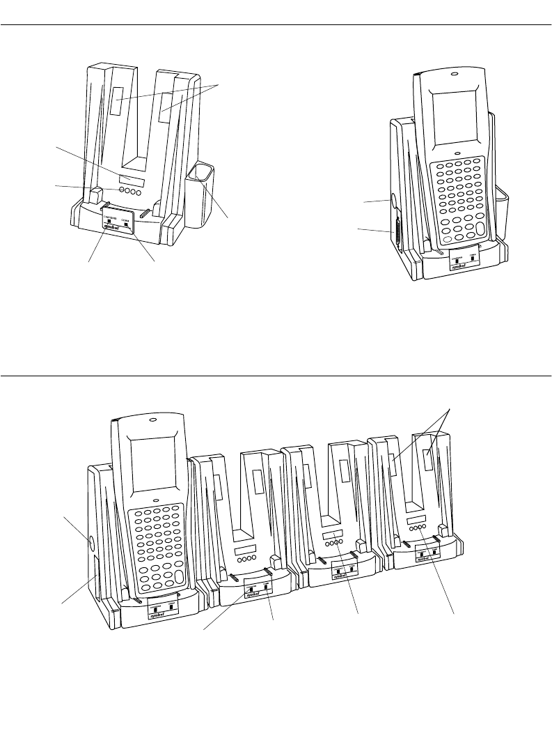
Accessories Setup
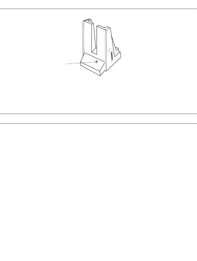
Parts of the CRD 38/6865
Figure 2-1. Parts of the CRD 38/6865
Parts of the CRD 38/6866
Figure 2-2. Parts of the CRD 38/6866
Screw Hole
Covers
Optical
Connectors
Battery
Contacts
Spare Battery
Charging Slot
Charging LED COMM LED
Power Port
Serial Port
Screw Hole
Covers
Battery
Contacts
Optical
Connectors
COMM LEDCharging LED
Power Port
Serial Port
2-4
PDT 6800 Series Product Reference Guide
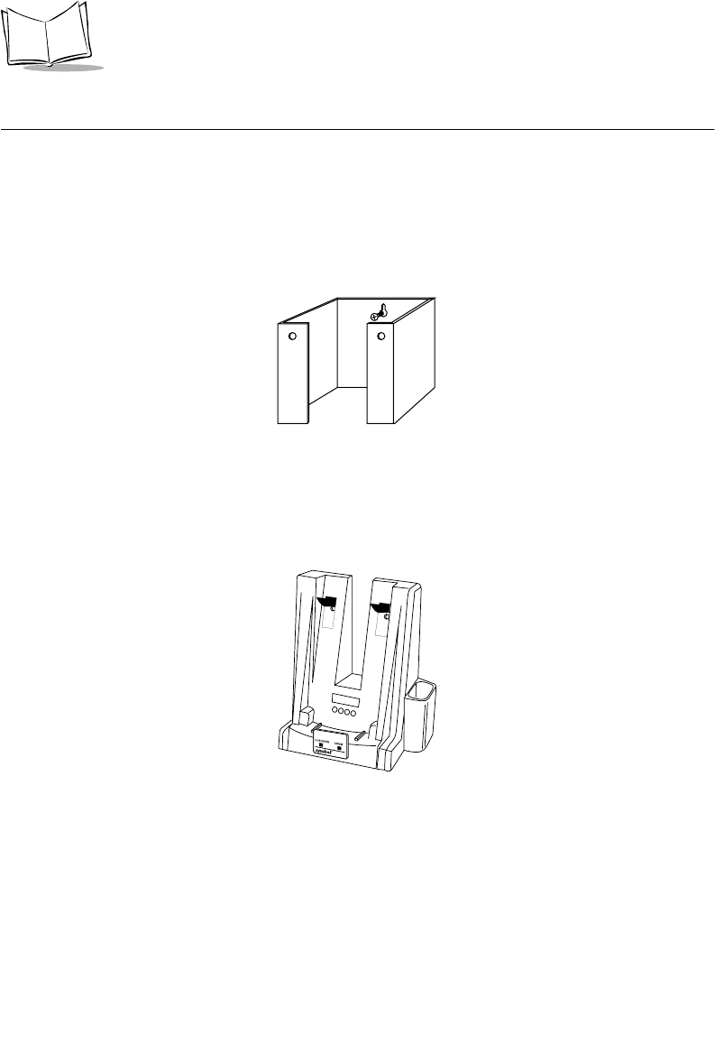
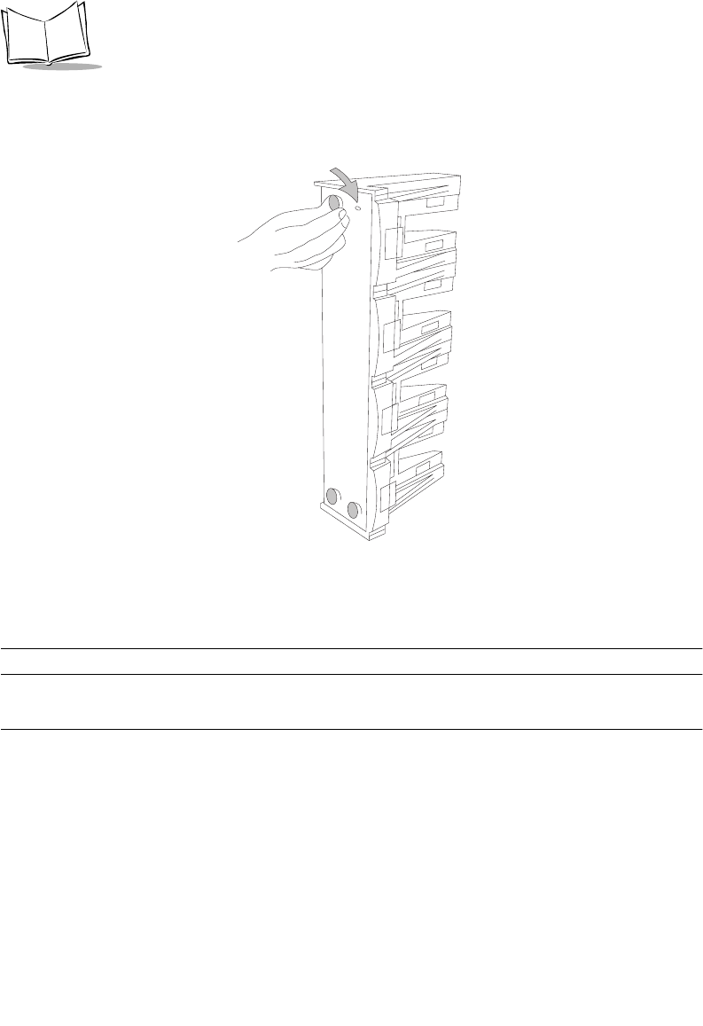
Wall Mounting the CRD 38/6865
The CRD 38/6865 can be wall-mounted on a wall bracket for convenience. To wall-mount
the 38/6865:
1. Mark where you want the cradle positioned on the wall.
2. Using a fastener appropriate to the wall construction, insert and secure the fastener
(Figure 2-3). Let the head protrude slightly.
Figure 2-3. Wall Mounting the 38/6865
3. Slide the bracket down over the head of the fastener.
4. Remove the black tape covers from the cradle screw holes ( Figure 2-4).
Figure 2-4. Removing the Tape Covers
2-5
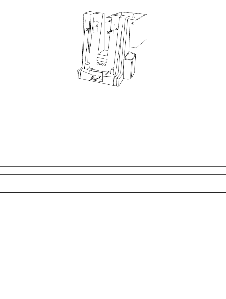
Accessories Setup
5. Position the cradle on the bracket.
Figure 2-5. Secure Cradle to Bracket
6. Secure the cradle to the bracket using two #10 metal screws (Figure 2-5).
Wall Mounting the CRD 38/6866
The CRD 38/6866 can be wall-mounted on two mounting brackets. Follow the directions for
Wall Mounting the CRD 38/6865 on page 2-4, using two brackets.
Table Mounting the CRD 38/6866
Note: Installing the suction cup feet is not mandatory but helps keep the
cradle in place.
1. On the bottom of the cradle, thread each of the four suction cup feet into the screw
holes.
2-6
PDT 6800 Series Product Reference Guide
2. Wet the base of each suction cup and secure the cradle to a smooth tabletop by
pushing firmly down on the cradle (Figure 2-6).
Figure 2-6. Installing Suction Cups on the CRD 38/6866
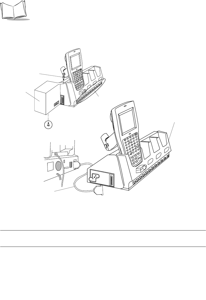
Connecting Power
Note: Connecting power to both CRD 38/6865 and CRD 38/6866 is the
same.
1. Connect the power supply cord’s round plug to the power port on the left side of the
cradle.
2. Connect the power supply’s AC plug to a standard electrical outlet.
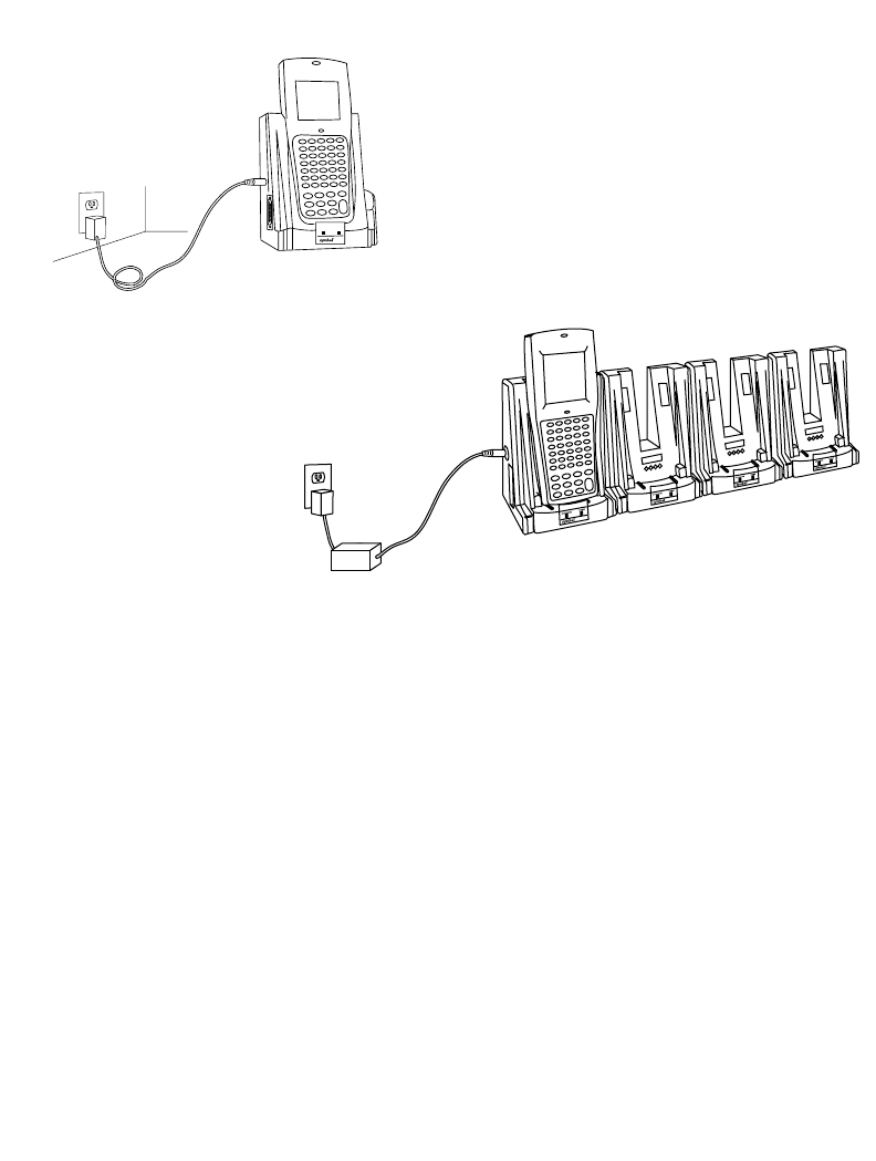
2-7
Accessories Setup
The green and red indicators light for 3 seconds, blink for 3 seconds, then go out.
Figure 2-7. Connecting Power to the CRD 38/6865 and CRD 38/6866
Connecting for Data Communications
To connect the CRD 38/6865 or CRD 38/6866:
1. Be sure to unplug the cradle’s power supply before connecting the serial cables.
2. Turn off the PC.
3. Plug the RS-232 serial cable’s DB-25 connector in the cradle’s communication port
(Figure 2-8).
4. Connect the cable’s other connector to the host computer’s serial (COMM) port.
CRD 38/6865
CRD 38/6866
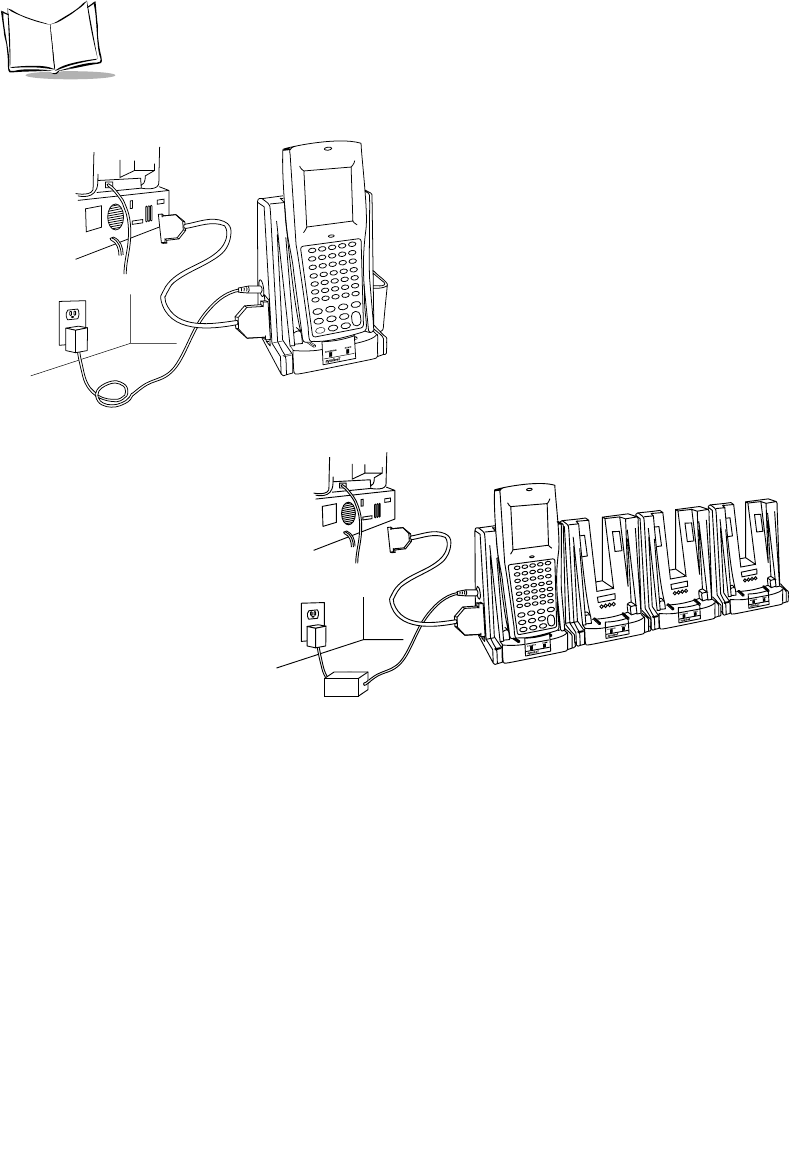
2-8
PDT 6800 Series Product Reference Guide
5. Reconnect the cradle’s power supply
Figure 2-8. Connecting the CRD 38/6865 and CRD 38/6866 for
Communications with Computer, Printer, or Modem
CRD 38/6865
CRD 38/6866
2-9
Accessories Setup
Connecting the CRD 38/6865 Internal Modem
Figure 2-9. RJ-11 Internal Modem Connection
Some cradles use an optional internal modem that communicates at rates of up to 14,400 bps
(with v.32 bit data compression). It can be connected directly to a telephone line through the
RJ-11 port shown in Figure 2-9.
Note: The four-slot cradle does not have an internal modem.
To connect the internal modem:
1. Connect the phone cord into the RJ-11 port on the back of the cradle.
2. Connect the other end of the phone cord into the wall phone jack.
Caution
When connecting the internal modem to the phone line, always connect the
phone line to the cradle first, then to the wall phone jack. When removing
the connection, always remove the telephone line from the wall phone jack,
then remove from the cradle.
There are specific firmware settings which are used to configure the modem’s hardware and
software for proper operation and regulatory compliance. The terminal’s application can
control these settings and enable you to view and amend the settings for country/region,
pulse/tone dialing, or repeat dial timing. Incorrectly defining these settings can lead to illegal
use of the modem and can create unreliable operation. The application developer should
consult the Series 3000 Application Programmer’s Reference Manual for correct settings.
RJ-11
Port
2-10
PDT 6800 Series Product Reference Guide
Connecting to the Telephone Network
A compliant telephone cord is required with an RJ-11 plug connection to the modem,
terminated with an appropriate and correctly wired local telecom connector compatible with
the telephone network. Such a cable may be obtained from your local supplier. Alternately,
compliant RJ-11 plugs to RJ-11 plug cables may be used with a range of adapters for
locations such as Europe.
Connecting the CRD 38/6866 to Other Cradles
Up to twenty-four CRD 38/6866 cradles can be connected in a series using an RS-232 inter-
cradle cable (p/n 60427-00-00) between each cradle.
Caution
Each cradle must have its own power supply; any other power hook-up
method is unsafe.
1. Plug one end of the inter-cradle cable into the communication port located on the
right end of the first cradle.
2. Plug the other end of the inter-cradle cable into the communication port located
below the power connector on the left end of the second cradle.
3. Connect the power supply to the second cradle as described in Connecting Power on
page 2-6.
4. Repeat the above steps for any additional cradles being added to the chain.
Figure 2-10. Connecting the CRD 38/6866 to Other Cradles
Chaining Interconnect Cable
(p/n 60427-00-00)
2-11
Accessories Setup
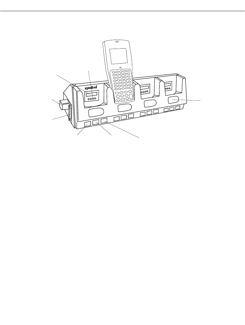
CCM 38/6860
Parts of the CCM 38/6860
Figure 2-11. Parts of the CCM 38/6860
Spare Battery
Charging Slot
Battery
Charge LED
Te r m i n a l
Charge LED
Terminal In
COMM LED
Battery
Charging
Contacts
Optical
Connectors
Power Port
Communications
Port
2-12
PDT 6800 Series Product Reference Guide
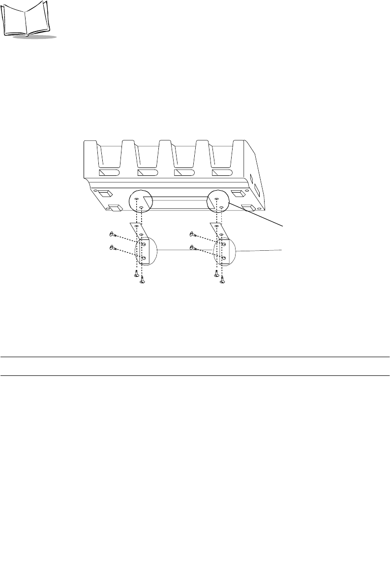
Wall Mounting
The CCM 38/6860 can be table or wall mounted.
To wall mount the CCM:
1. Attach the wall-mounting brackets to the bottom of the CCM using the screws
provided (Figure 2-12)
Figure 2-12. Wall Mounting the CCM
2. Position the CCM with attached brackets on the wall.
3. Insert the appropriate wall-mounting hardware into the bracket holes as shown in
Figure 2-12 and secure.
Note: Appropriate wall-mounting hardware is provided by customer.
Coupling CCMs
Up to four CCM 38/6860s can be coupled together for table or wall mounting, with power
provided by a single power supply attached to the left-most CCM. To couple two or more
CCMs for table or wall mounting:
1. Verify that add-on kit p/n 3861-101 contains the following parts:
"1 CCM
"1 coupling bracket
"6 cross-head screws
"2 flat-head screws
Step 1
Step 2
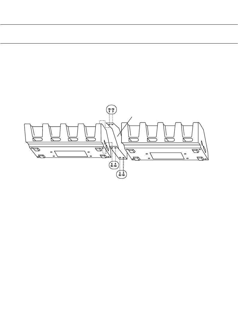
2-13
Accessories Setup
2. On the add-on (or right-hand) CCM, use a 3/16-inch driver and remove the jack
screws, securing the communications port, and replace them with the flat-head
screws ONE AT A TIME.
Note: Be sure to remove the jack screws one at a time; otherwise, the
connector will fall into the housing.
3. Mate the power port on the right side of the first cradle with the power port on the
left hand side of the second cradle.
4. Place the coupling bracket between the CCMs, aligning the holes in the coupling
bracket with the holes in the CCM’s base (Figure 2-13).
5. Install 6 cross-head screws through the coupling bracket into the CCMs and tighten.
6. To wall mount the coupled CCMs, refer to Wall Mounting above.
Figure 2-13. Coupling Two CCMs
Connecting Power
Only the power connection is required for charging batteries in the CCM.
1. Install the power supply.
a. Attach the power supply to the left side of the CCM as shown in Figure 2-14
using two cross-head screws.
b. Connect the power supply plug to an AC wall outlet.
Screws Coupling
Bracket
Screws
2-14
PDT 6800 Series Product Reference Guide
2. When the CCM is connected to power, all the LEDs flash at the same time for 3
seconds, flash once from left to right, and then turn on for 3 seconds before going
out.
Figure 2-14. Connecting the CCM 38/6860 for
Charging and Communications
Connecting the CCM for Serial Communications
Note: Both the communications cables and the power supply connection are
required for performing communications through the CCM.
1. Turn off the PC.
2. Plug the RS-232 null modem cable’s DB-25 connector in the cradle’s communication
port.
+-
+-
Power Supply
Insert Screw
Insert Screw
LEDs
CCM
Null Modem Cable
2-15
Accessories Setup
3. Connect the cable’s other connector to the host computer’s serial (COMM) port.
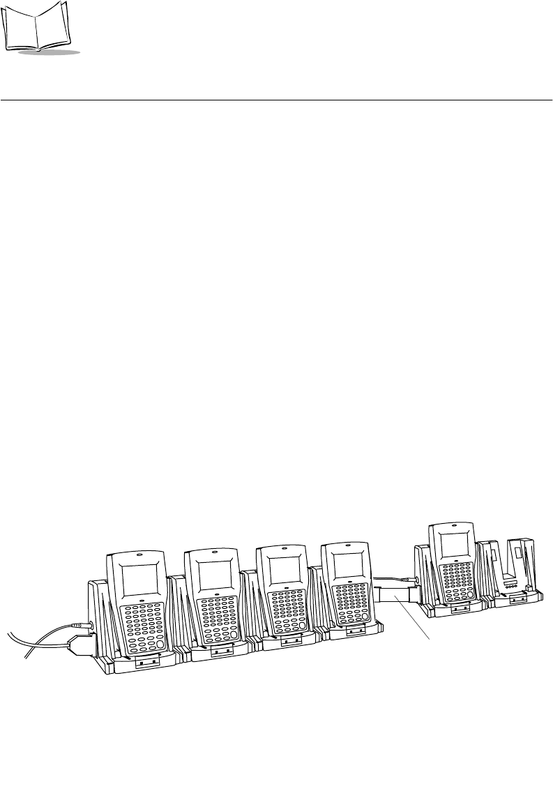
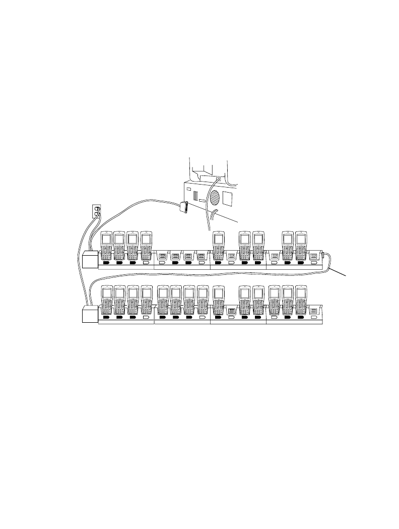
Daisy-Chaining Two or More CCMs
Up to twenty-four CCMs can be daisy-chained together for charging and communications.
To daisy chain two or more groups of four CCMs requires:
!one 25-pin, male-to-female, straight-through RS-232 cable per group of coupled
CCMs
!one power supply per group of coupled CCMs.
Depending on how close together you place the CCMs, the cables can be from 1-foot to 10-
feet long.
Figure 2-15. Daisy-Chaining Multiple CCMs
To chain the CCMs:
1. Couple the CCMs as directed in the section Coupling CCMs.
2. In the first coupled section, connect the serial cable to the left-most CCM.
3. Connect the RS-232 cable’s (male or female) DB-25 connector in the serial port of
the right-most CCM in the first coupling.
4. Connect the (male or female) DB-25 in the serial port of the left-most CCM in the
second coupling.
One Power Supply
and RS-232 Cable
per Group of
Coupled CCMs
First
Coupled
Group
Second
Coupled
Group
RS-232
Cable
(a “Group” Can
Number from
1 to 4 CCMs)
2-16
PDT 6800 Series Product Reference Guide
5. Connect the power supplies for each coupled section as directed in Connecting
Power.
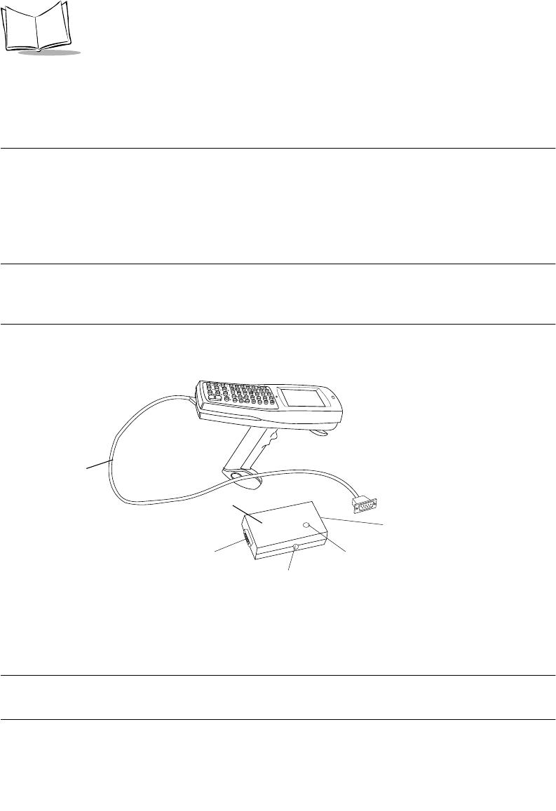
PC Adapter
The PC Adapter works with the Printer Interface Module (PIM) so you can:
!Communicate to and from the PC without a CCM 38/6860, CRD 38/6865, or CRD
38/6866 cradle
!Charge the NiCd battery pack in the terminal without a cradle.
Note: The Lithium Ion battery DOES NOT charge when the PC Adapter
and PIM are connected. Use the UBC 2000 battery adapter p/n 21-
32665-24 to charge the Lithium Ion battery.
Parts of the PC Adapter
Figure 2-16. Parts of the PC Adapter
!The Battery Charge Indicator LED flashes when the terminal power is turned on and
while the NiCd battery pack is being charged.
Note: When power to the PC Adapter is turned on, NiCd battery charging
begins automatically and continues for 7 hours.
PIM
RS-232
Pin Port
DB-9 Connector
Battery Charge
Indicator LED
Power Supply Port
PC Adapter
2-17
Accessories Setup
The LED flashes once when the terminal is turned on. It remains steady while the
terminal is powered and blinks slowly during downloading.
!The RS-232 25-pin port attaches the null modem cable connected to a PC or other
RS-232 device. See Appendix A, Null Modem Pin-outs for null modem pin-outs.
!The DB-9 connector attaches the PIM’s DB-9 connector.
!The power supply port attaches the 15-Volt power supply.
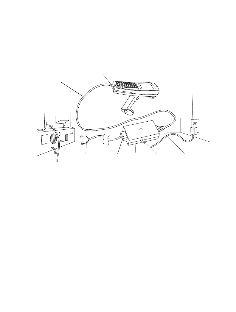
Connecting the PC Adapter to the Terminal and Serial Device
Figure 2-17. Setting Up the PC Adapter
1. Turn the PC and terminal OFF.
2. Plug the PIM’s DB-9 connector in the PC Adapter’s DB-9 port.
PIM
DB-9 Port
PIM’s Optical
Connector
PC
Adapter
DB-25RS-232 Cable
Connector
Power Supply
Power
Supply
Port

2-18
PDT 6800 Series Product Reference Guide
3. Attach the PIM’s optical connector to the terminal by inserting the clips on the
connector in the slots on either side of the port (Figure 2-18).
Figure 2-18. Attaching the PIM’s Optical Connector
1. Connect the RS-232 cable’s DB-25 connector in the PC Adapter’s RS-232 port.
2. Plug the other end of the RS-232 cable in the RS-232 device (e.g., host PC).
3. Plug the jack end of the 16-Volt power supply into the power supply port.
4. Plug the 15-Volt power supply’s cube into an electrical outlet. The Battery Charge
Indicator LED flashes when the terminal is powered on.
Clips
Slots
Optical
Port
PIM Cable
PIM Optical
Connector

3-1
Chapter 3
Batch and Spectrum One Terminal Setup
Introduction
Before using the PDT 6800 Series terminal, perform the following:
!Install the battery (refer to Chapter 6, Maintaining the Terminal)
!Charge the battery (refer to Chapter 6, Maintaining the Terminal)
!Load the system files and application(s) (refer to Series 3000 Application
Programmer’s Guide p/n 70-16308-XX).
Hardware Requirements
Following is the equipment required to initialize a batch or Spectrum One radio terminal:
!PDT 6800 (batch) or PDT 6810 (Spectrum One) terminal
!One or more CCM 38/6860 or CRD 38/6866, or a CRD 38/6865
!OR
!PC adapter with Printer Interface Module (PIM)
!RS-232 null modem cable
!Power Supply
!Host Computer.
Refer to Chapter 2, Accessories Setup for setting up the cradles or PC Adapter for
communications.

3-2
PDT 6800 Series Product Reference Guide
Communications
For terminals being used in a direct communications (batch) environment or a Spectrum One
network environment, applications are transferred from a host computer to the terminal:
!over a communications line using a null modem connected to the cradle
OR
!through the PC Adapter.
The procedure uses the SENDHEX program on the host computer and the Program Loader
function (from Command Mode) on the terminal.
Programs are stored in the terminal’s nonvolatile memory (NVM), also called the application
EEPROM.
Note: For details on the SENDHEX program, refer to the Series 3000
Application Programmer's Manual.
Other software may be used in place of the SENDHEX program.
Downloading the Program
To download the program, initiate the communications software on the host computer and
terminal as described in the following sections.
Note: To cancel communications at any time during the session, press
CLEAR on the terminal. The session stops immediately.
Communications parameters specified on the host and the terminal
must match. These parameters typically are:
38400 bps
7-bit parity
Odd parity
Xon/Xoff flow control
To program the EEPROM, the terminal must be connected to the
host through a cradle, CCM 38/6860, or PC Adapter with PIM.

3-3
Batch and Spectrum One Terminal Setup
Initiate Host Communications Software
If using a cradle (CCM 38/6860, CRD 38/6866, CRD 38/6865), do steps 1-3. Otherwise
continue with step 4.
1. Connect the cradle to the host computer. Refer to Chapter 2, Accessories Setup.
2. Power on the cradle.
3. Place the terminal in the cradle.
4. Connect the PC adapter.
5. Power on the host computer.
6. Start the communications program.
7. At the DOS prompt, enter the SENDHEX command:
sendhex pgmname 38400 com2
where:
In the example, the baud rate is set to 38400 bps and the communications port to
COM2. The default values are accepted for the remaining parameters.
Note: Versions of SENDHEX earlier than 3.0 do not support flow control.
If you use an earlier version and encounter communication errors, use
a lower baud rate.
8. SENDHEX displays the prompt:
Press <Enter> to begin communications.
9. Do NOT press <ENTER> yet. Before starting communications (refer to Starting
Communications on page 3-6), set up the terminal as described in Initiate Terminal
Communications.
SENDHEX is the command
pgmname is the application being loaded (.hex extension is optional)
parameters are the communications parameters following the program
name. Parameters include baud rate, communications port,
data bits, parity, and flow control. To accept the default
parameters, do not enter a value.

3-4
PDT 6800 Series Product Reference Guide
Initiate Terminal Communications
1. Boot the terminal to command mode.
For the 35-Key terminal:
"Press and hold <BKSP> and <SHIFT>.
"Press and release PWR.
"Release <BKSP> and <SHIFT>.
For the 46-Key terminal:
"Press and hold <F> and <I>.
"Press and release <PWR>.
"Release <F> and <I>.
The terminal displays:
COMMAND MODE
Select function
Self test
2. Scroll through Command Mode options using UpArrow or DownArrow until
"Program loader" is displayed. Press <ENTER>.
3. The terminal displays:
Program loader
WARNING: EEPROM
WILL BE ERASED
CONTINUE? <ENT>
Before loading the new application, erase the NVM’s original contents.
Note: To cancel this operation, press CLEAR.
4. Press <ENTER> to erase the EEPROM.
Wait while the EEPROM is erased. When complete, the program prompts for the
communications parameters.

3-5
Batch and Spectrum One Terminal Setup
5. Baud Rate - the terminal displays:
Comm Parameters
Baud
4 9600
Scroll through the list using UpArrow or DownArrow. When the correct rate is
displayed (38400 is recommended), press <ENTER>.
6. Data Bits - the terminal displays:
Comm Parameters
Data Bits
7
Press <7> (recommended) or <8> to specify data bits, or scroll through the list using
UpArrow and DownArrow. Press <ENTER> when the correct value is displayed.
Note: If 8 data bits is selected, the program selects "No parity" and skips
the next step.
7. Parity - if 7 data bits is selected, the terminal displays:
Comm Parameters
Parity
Odd
Press the first letter of a parity option (Even, Odd, None, Space, or Mark), or scroll
using UpArrow and DownArrow and press <ENTER> when the correct value is
displayed.
8. Flow Control - the terminal displays:
Comm Parameters
Flow Control
None
Press the first letter of a flow control option (None, Xon/Xoff, or RTS/CTS), or scroll
using UpArrow or DownArrow and press <ENTER> when the correct value is
displayed.

3-6
PDT 6800 Series Product Reference Guide
Starting Communications
1. The terminal is ready to receive the program from the host PC and displays:
Comm Parameters
Start? <ENT>
2. Press <ENTER> on the terminal.
3. Press <ENTER> on the host computer. The SENDHEX program begins transmitting
the program image. When communications are established, the terminal displays:
Program loader
Receiving: XXXX
where XXXX is the program segment address being transferred.
4. When the transmission is complete, the terminal displays:
Program loader
Status 0000
A status of 0000 (all zeros) indicates a successful transfer. Other status values
indicate an error. These values are provided in Appendix C, Communications Status
Codes.
If you received an error, press CLEAR on the terminal to return to the Command
Mode main menu.
Ending Communications
To return to the Command Mode main menu:
1. Press CLEAR on the terminal.
2. Power down the terminal.
3. Detach any cables connected to the terminal.
4. Reboot the terminal using the appropriate cold boot sequence. Refer to Booting the
Ter m in a l on page 5-4.

4-1
Chapter 4
Spectrum24 RF Terminal Setup
Spectrum24 Terminals
In Spectrum24 terminals, wireless connectivity is accomplished using standard
communications protocols. Because they are standard, the protocols are generalized and take
up considerably more space on the terminal’s NVM than is required for Spectrum One ®
terminals. Because there is less space available in NVM for application files, the terminal
operates with an additional megabyte of non-volatile memory or flash disk. This extra
memory is used to reduce not only the boot times but also the time and resources required to
load applications into the terminal. The flash disk also offers the possibility of running
multiple applications from the same terminal (refer to the Spectrum24 Setup and Utilities
Reference Guide p/n 72-50795-01 for more information). With version 3.03 or later of the
system software (LWP.HEX), the terminal can also run diagnostic tools.
Accessing the Flash Disk
The flash disk is accessed through a driver, FLASHDSK.SYS, which makes the flash disk
appear to a program as another disk drive (E:). The drive has characteristics of fast reading
but slow writing (for example, even for the smallest files, the write process takes 3-4 seconds).
These characteristics make it ideal for files that are written once, accessed often, and seldom
updated.
We recommend that you use the flash disk (E:) mainly for application and configuration file
storage. It is important to note that because of the slow writing time (3-4 seconds), writing
files during a power interruption (low battery, dead battery, suspend, power off, or power
failure) could corrupt the disk. Be sure to only write data to the disk with the terminal
connected to external power or with the battery fully charged to avoid problems. To avoid
overwriting the flash disk by mistake, the flash disk is set to read-only mode for normal

4-2
Series 6800 Product Reference Guide
operation. The software installation or application software takes care of write/read mode
switching for you.
Standard Spectrum24 Software
The terminal comes with the system software installed, including:
!Spectrum24 radio drivers
!TCP/IP software
!configuration files
!various utilities.
A BIOS of version 3.08 or later is required.
The default files cover most expected installations/initializations with minor changes as
detailed in this chapter.
If your requirements are more advanced, refer to the Spectrum24 Network Terminal
Technical Reference Guide (p/n 70-20193-XX) for more information on the Spectrum24 RF
network, SLAODI.COM, the Symbol-provided ODI driver, and the configuration file setups
required for various platforms.
Refer to the Spectrum24 Setup and Utilities Reference Guide (p/n 72-50795-XX) for more
information on Spectrum24 boot options, addressing, initializing the terminal, and Access
Point (AP) associations.

5-1
Chapter 5
Operating the PDT 6800 Series
Introduction
This chapter describes how to operate a PDT 6800 Series terminal, including:
!Powering the terminal on and off
!Booting the terminal
!PDT 6842 - Switching 802.11 to Spring RF protocol
!Adjusting the display contrast
!Entering data using the keyboard
!Entering data using the scanner
!Communicating with a PC or printer
!Communicating on an RF network.

5-2
PDT 6800 Series Product Reference Guide
Powering the Terminal On
There are several ways to power on a terminal. Each way lets you resume at the same location
in the application where you left off.
Note: The PDT 6800 Series terminal always checks for enough battery
power for safe operation before it powers on.
Removing Terminal From a Cradle
The terminal automatically powers on when it is removed from a cradle. While the terminal
is in the cradle, the NiCd battery is constantly being charged. If you remove the terminal from
the cradle but do not use it right away, press the PWR key to turn it off, or let it power off
automatically. Refer to the section Restoring Power After Automatic Shutdown on page 53.
Note: The Lithium Ion battery is charged in the UBC 2000 battery adapter
p/n 21-32665-24, not in the cradle.
Keyboard
Your terminal can be programmed to power on from the keyboard by:
!Pressing the PWR key only
!Pressing any key.
If you press the PWR key while the terminal is in the cradle, the terminal powers on. If you
leave the terminal in the cradle and press PWR to turn the terminal off, it appears to turn off,
but is on very low power.
See the Series 3000 Application Programmer's Guide for more information on programming
your keyboard.
Real-Time Clock
If the application program allows it, the terminal can be powered on by the real-time clock.
This lets the terminal perform unattended operations such as an overnight communication
session.

5-3
Operating the PDT 6800 Series
Laser Trigger
If the application program allows, you can power on the terminal by pulling the trigger.
Restoring Power After Automatic Shutdown
The terminal shuts off if you do not use it for an amount of time set by your application. Press
the PWR key or press the trigger to restore power and return to your application.
Powering the Terminal Off
To perform a normal power off, press the PWR key or let the terminal shut down
automatically as programmed. See your application guide or the section Restoring Power
After Automatic Shutdown for more information. Consult your system administrator if you
are unable to power off the terminal.
Forcing Power Off
If pressing the PWR key does not turn off the terminal, force the power off to reduce battery
drain and preserve your data.
To force power off, press and hold the PWR key for 15 seconds, until the terminal powers
down.
Restarting After a Forced Power Off
When a terminal is powered off because of software or hardware failure, use the following
methods to restart:
!Use the warm-boot procedure for a software failure.
!When a warm boot fails, use the cold-boot procedure.
!If a system software problem in the nonvolatile memory (NVM) occurs, see
Chapter 3, Batch and Spectrum One Terminal Setup.
Note: Do not use the PWR key to restart a terminal when it was forced off
due to defective system or application software in the NVM. Pressing
the PWR key causes the program to resume where it stopped, trying
to perform the same unsuccessful operation.

5-4
PDT 6800 Series Product Reference Guide
Booting the Terminal
Powering the terminal on does not boot the system or initialize the program or data. To
initialize the terminal, perform either a warm boot or cold boot.
Warm Boot
A warm boot resets the operating system while preserving the program and data on the RAM
disk. This process is similar to pressing the <Ctrl+Alt+Del> keys on a PC, except that it does
not clear the system’s memory. To perform a warm boot:
For the 35-Key terminal:
"Power the terminal off
"Press and hold <F> and <J>
"Press and release <PWR>
"Release <F> and <J>.
For the 46-Key terminal:
"Power the terminal off
"Press and hold <4> and <5>
"Press and release <PWR>
"Release <4> and <5>.
The terminal displays configuration information, copyright, RAM size, and expanded
memory RAM size. Other information displayed depends on the operating system, installed
device drivers, and AUTOEXEC.BAT commands. If this warm boot procedure fails to restart
the terminal, use the Cold Boot procedure.
Cold Boot
A cold boot fully resets the system and clears memory, including the RAM disk. Any
programs and data stored in memory or on the RAM disk are deleted. Nonvolatile memory
(NVM - the Application EEPROM) is not affected. If the cold-boot procedure fails to restart
the terminal, see Chapter 7, Error Recovery and Troubleshooting.
Caution
This procedure permanently erases all data and software in the terminal un-
less they reside in NVM. Contents of RAM are lost.

5-5
Operating the PDT 6800 Series
To perform a cold boot:
For the 35-Key terminal:
"Power the terminal off
"Press and hold <SPACE>, <FUNC>, and Up Arrow
"Press and release <PWR>
"Release <SPACE>, <FUNC>, and Up Arrow.
For the 46-Key terminal:
"Power the terminal off
"Press and hold <A>, <B>, and <D>
"Press and release <PWR>
"Release <A>, <B>, and <D>.
The terminal displays version information, copyright, RAM size, and installed expanded
memory RAM size. Other information displayed depends on the operating system, installed
device drivers, and AUTOEXEC.BAT commands.
Cold-Boot Failure
During a cold boot, the system briefly displays a status line for each driver as it loads in the
format:
0: Driver #.##
The line shows a status value, usually 0, followed by the name and version number of the
driver. If the system halts at one of these lines and displays a status value other than 0, the
displayed device driver failed to load properly.
If such a failure occurs, try cold booting the terminal again. If this does not solve the problem,
call the Symbol Support Center.
More troubleshooting information is provided in the publications listed in Related
Publications on page x.

5-6
PDT 6800 Series Product Reference Guide
PDT 6842 - Switching 802.11 to Spring RF Protocol
After a cold boot, the PDT 6842 boots up with the 802.11 RF protocol. If you are using the
Spring RF protocol, do the following to switch from 802.11 to Spring:
1. Cold boot the terminal. The following prompt displays:
SOFTWARE UPDATE
Update?[y/n]:
2. Within four seconds, type the letter “y”. If you do not type the letter “y” within four
seconds, the terminal boots up with the 802.11 RF protocol.
The next prompt displays:
RF PROTOCOL UPDATE
OPPORTUNITY
Update RF protocol
[y/n]:
3. Within ten seconds, type the letter “y”. If you do not type the letter “y” within ten
seconds, the terminal boots up with the 802.11 RF protocol.
The next prompt displays:
RF Protocol
Currently 802.11
1. Abort update
2. Make pre-802.11
3. Make 802.11
Select[1,2,3]:
4. Select 2 to boot up with the Spring RF protocol.
The next prompt displays:
Enter password
→
5. Enter the password RFPROT, then press ENTER. The terminal continues to boot up.
The procedure to switch to the Spring RF protocol is complete. If a compatibility problem
exists, the terminal pauses with an error message. Contact your System Administrator.

5-7
Operating the PDT 6800 Series
Boot to Command Mode
Command Mode provides functions for:
!Running the Self-Test program to verify that the hardware is operating properly
(refer to Chapter 7, Error Recovery and Troubleshooting).
!Performing a Memory Transfer to upload data from a terminal to a host system (refer
to Chapter 7, Error Recovery and Troubleshooting ).
!Performing a Program Download to transfer an application from the host to a
terminal (refer to Chapter 3, Batch and Spectrum One Terminal Setup).
To boot to Command Mode:
For the 35-Key terminal:
"Power the terminal off
"Press and hold <BKSP> and <SHIFT>
"Press and release <PWR>
"Release <BKSP> and <SHIFT>.
For the 46-Key terminal:
"Power the terminal off
"Press and hold <F> and <I>
"Press and release <PWR>
"Release <F> and <I>.
Adjusting the Display
Display Contrast
The screen’s contrast is adjustable to eight levels, making the display more readable in
different lighting conditions, at various temperatures, and at different viewing angles.
!To reduce (lighten) display contrast, press FUNC Y.
!To increase (darken) display contrast, press FUNC X.
Backlighting
The backlight illuminates the display in dimly lit areas.
5-8
PDT 6800 Series Product Reference Guide
Note: Use of backlighting can significantly reduce battery life.
To turn the backlight on or off, press FUNC then L, or use the key sequence listed in your
application guide. The backlight turns off automatically when the terminal is powered off or
when the terminal has not been used for an amount of time set by the application. See the
Series 3000 Application Programmer's Guide for more information.
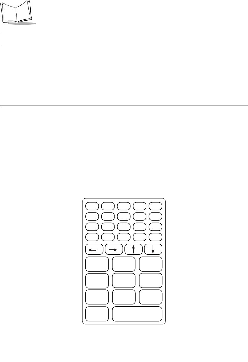
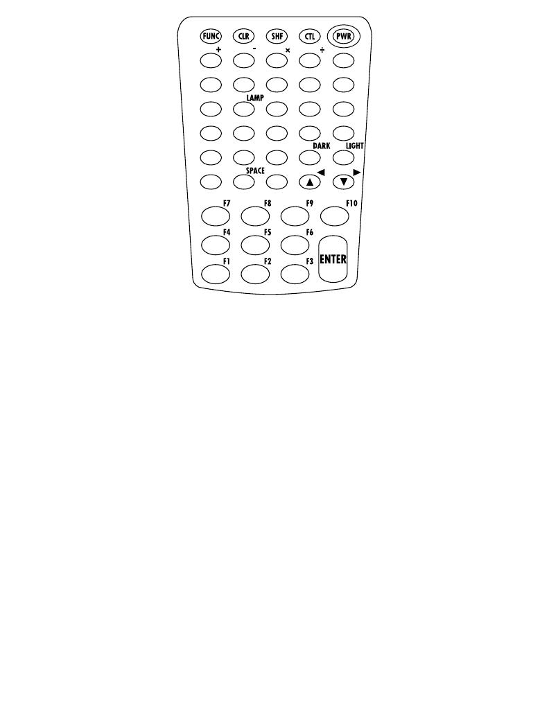
PDT 6800 Series Keyboard
The keyboard is used for entering data and issuing commands to the terminal. Figure 5-1 and
Figure 5-2 illustrate the standard 35-key and 46-key keyboards respectively. The keys on the
keyboard are distinguished as modifier keys and character keys. Because terminal keyboards
have fewer keys than PC keyboards, each character key can produce more than the usual one
or two characters. The modifier keys, SHF (Shift), CTL, and FUNC, used individually or in
combination, determine which character or special function the character keys produce.
Because the keyboard is programmable, your terminal may not work as described here. For
more information and illustrations of other keyboard states, see the Series 3000 Application
Programmer's Guide and your application guide.
Figure 5-1. 35-Key Keyboard
ENTER
0
Z
123
6
9
8
5
7
4
F10
W
T
QR
U
XY
V
S
FUNC ALPHA CLEAR SHIFT PWR
BKSP SPACE CTRL [ A ] B
' C = D * E / F - G
+ H . I , J \ K ; L
MNO P
F1 F2 F3
F6F5F4
F9F8F7
5-9
Operating the PDT 6800 Series
Figure 5-2. 46-Key Keyboard
Using the Keyboard
Except during boot operations, the terminal expects the operator to press keys one at a time.
If the terminal has been programmed for it (ERR3000 is loaded), and if two or more keys are
pressed simultaneously, the terminal indicates a Double-Key.
The keyboard also has an optionally configurable auto-repeat function. If the application
allows, a character repeats as long as the key is held down. If the key is pressed immediately
following a modifier key, the modifier sequence affects only the first occurrence of the
character key.
Modifier Keys
The Shift, Alpha, Function, and Control keys are modifier keys. When pressed individually
or in certain combinations, these keys change the keyboard state and possibly the character
produced by the character key subsequently pressed. Refer to Table 5-1 for a list of the
terminal’s special keys.
For example, pressing <FUNC> followed by <CTRL> produces Alt characters, with the same
effect as pressing the Alt key on a PC.
=
BKSP .
7890
456
123
ABCDE
FGH IJ
KLMNO
PQRST
UVWX Y
Z

5-10
PDT 6800 Series Product Reference Guide
To cancel the effect of a modifier key, press it again.
Keyboard Speed
If your application program allows it, the characters may be set to appear faster or slower.
Refer to the Series 3000 Application Programmer's Manual for more information.
Keyboard States
The keyboard states are listed below in the order in which they take priority, unless changed
by the application.
Unshifted
Shifted
Function
Control
The standard cursor shapes for the keyboard states are shown in Table 6-1 on page 6-2.
Momentary and Locked States
Each keyboard state is either momentary or locked. A momentary state lasts for only the
following keystroke. A locked state lasts until the activator key is pressed again.
Only one momentary state can be active at a time. Momentary states always take priority
over locked states. If you press several momentary state keys in a row, the system changes to
the state of the last key pressed. For example, if you press SHF, then CTRL, the terminal
enters the CONTROL state.
The CTRL, SHF, and FUNC keys activate a momentary state. If you press a momentary state
key twice in a row, the system enters the state and then cancels it. For example, if you press
SHF, SHF, the terminal is shifted and then immediately unshifted.
When batteries are low, the cursor changes. See Cursor Indicators, Table 6-1 on page 6-2.
When an operator ends a momentary state (by toggling it off or by completing the key
sequence), the system returns the keyboard to the last active locked state.
Note: Pressing the FUNC key does not clear the last momentary state.
However, pressing another momentary key after FUNC clears the
FUNCTION state.

5-11
Operating the PDT 6800 Series
Table 5-1. Special Keys
Key Name
35-Key
Key Name
46-Key
Description
CTRL (Control) CTL (Control) Invokes the control command.
FUNC (Function) FUNC (Function) Invokes the function command for certain utilities,
such as turning on the back light.
"Press FUNC and the corresponding numeric key
to produce function keys F1 to F10.
"Press FUNC, then to scroll left and FUNC to
scroll right.
"Press FUNC then BKSP to enter a blank space.
BKSP (Backspace) BKSP (Backspace) Erases information entered on the display one
character at a time. Information erased this way
cannot be recovered. This key is also used to
produce a break by pressing CTL, BKSP.
PWR (Power) PWR (Power) Turns the terminal on and off.
CLEAR CLR (Clear) Partially or completely escapes from an application
level or screen. CLR also clears all data typed from
the display.
SHIFT SHF (Shift) Accesses the shifted keyboard.
ENTER ENTER Places entered data into the terminal’s memory.
Move the cursor up, down. Press FUNC then to
scroll left; press FUNC then to scroll right.
Arrow key use depends on the application.
Moves the cursor up, down.
Move the cursor left, right.
ALPHA Shifts the keyboard to produce alphabetic
characters.
SPACE Places a blank space on a line of the display.
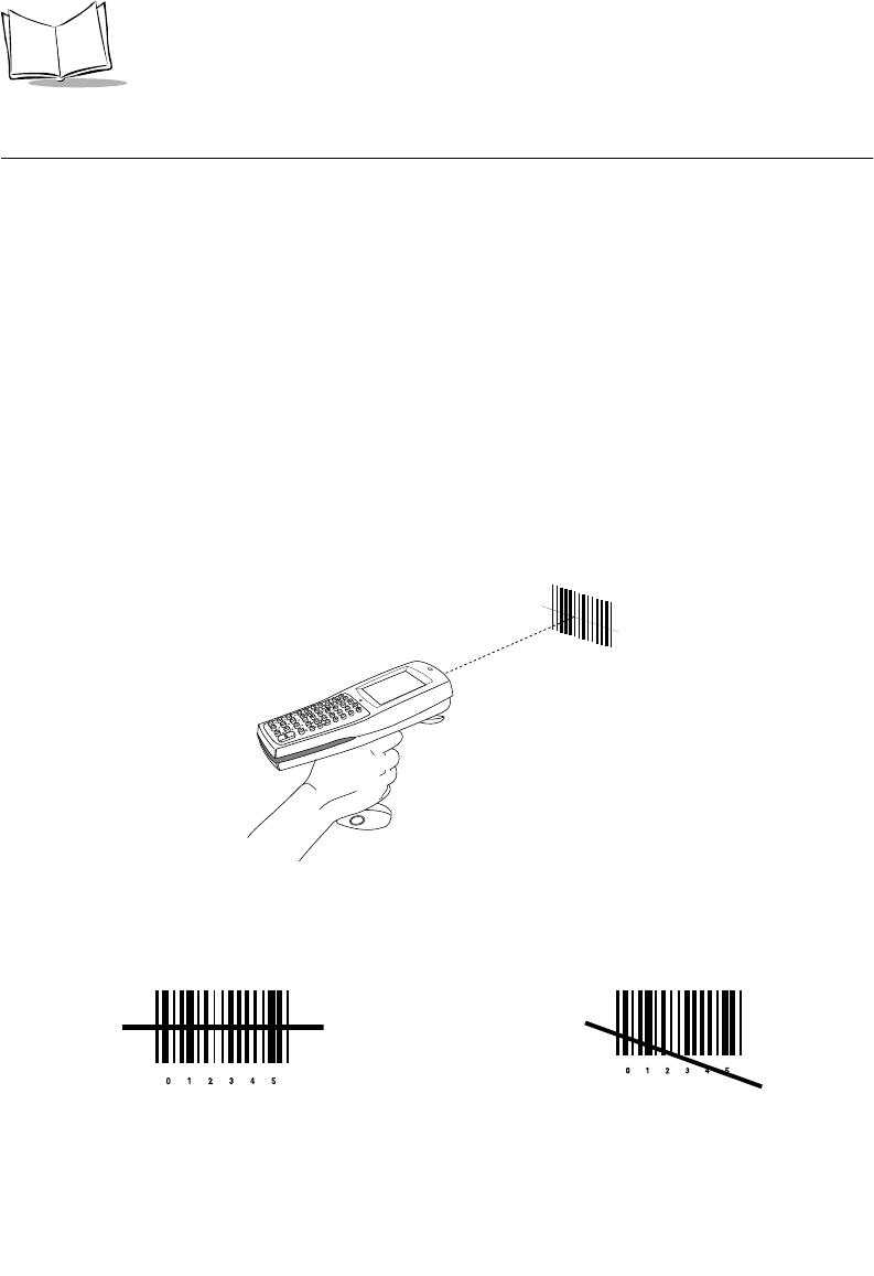
5-12
PDT 6800 Series Product Reference Guide
Scanning
The PDT 6800 has an integrated scanner which allows you to collect data by scanning 1 or
2 dimensional bar codes. See Appendix F, 2D Scanner Drivers and Applications for
information on enabling the 2D scanner.
Before scanning can occur, the terminal must be running an application that supports bar
code scanning. The terminal must also be programmed to scan the type of bar code you want,
such as Universal Product Code (UPC) or Code 3 of 9. For information on scanning
applications and on programming the scanner, refer to the Series 3000 Application
Developer’s Kit.
Scanning 1D Bar Codes
1. Pull the trigger on the handle to power on the terminal and laser scanner. The Scan
LED turns red if scanning is enabled and the laser is on.
2. Point the terminal at a slight angle to the bar code and pull the trigger.
Figure 5-3. Using the Laser Scanner
3. Ensure that the scan beam crosses all bars and spaces on the 1D bar code symbol, as
shown below. Do not hold the scanner directly over the bar code.
Right Wrong
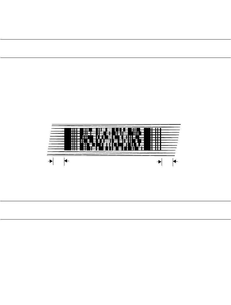
5-13
Operating the PDT 6800 Series
4. Hold the scanner farther away for larger symbols, and closer for symbols with bars
that are close together. Optimal scanning distance varies with bar code density and
scanner optics, but more combinations work within 4 to 10 inches.
5. If the decode is successful, the screen displays the code and the Scan LED turns from
red to green. The terminal may also beep.
Note: The procedure for your scanner may differ from the one given above.
Scanner use depends on the application.
Scanning 2D Bar Codes
The terminal supports PDF417 bar code scanning. The raster pattern has multiple scanning
rows to accommodate the PDF417 symbol’s multiple rows.
1. Point the scanner at the bar code and press the trigger.
2. As the raster pattern spreads, keep the pattern in the same horizontal plane as the
bar code.
Figure 5-4. Raster Pattern
3. If the decode is successful, the screen displays the code and the Scan LED turns from
red to green. The terminal may also beep.
Note: The procedure for your scanner may differ from the one given above.
Scanner use depends on the application.
3/4”3/4”
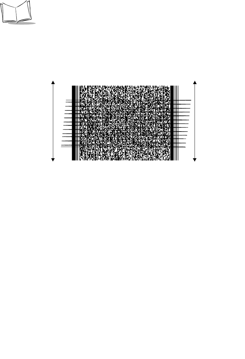
5-14
PDT 6800 Series Product Reference Guide
“Tall” PDF Bar Codes
If the PDF417 symbol is “tall,” the vertical scan pattern may not be high enough to cover it.
In this case, try a slow “up and down” scanning motion. With the raster pattern open, move
the terminal slowly down toward the bottom of the symbol, keeping the beam horizontal to
the rows, then slowly back up toward the top.
Figure 5-5. Scanning Tall PDF Bar Code
The scan beam does not have to be perfectly parallel with the top and bottom of the symbol.
Scanning Considerations
Usually, scanning is a simple matter of aim, scan, and decode, and a few quick trial efforts
master it simply and intuitively. However, two important considerations can optimize any
scanning technique — angle and range.
Aiming: Hold at an Angle
Do not hold the terminal’s scan window directly over the bar code.
Laser light reflecting directly back into the scan window from the bar code is known as
specular reflection. This strong light can “blind” the scanner and make decoding difficult.
The area where specular reflection occurs is known as a “dead zone”.
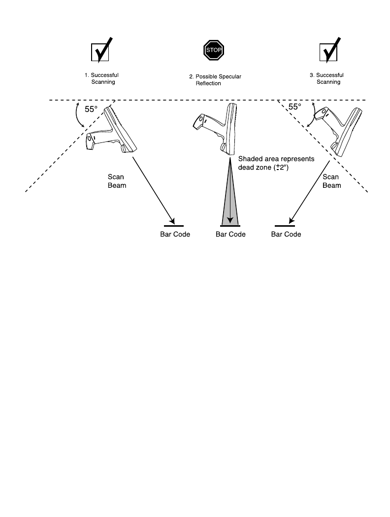
5-15
Operating the PDT 6800 Series
You can tilt the terminal up to 55° forward or back and achieve a successful decode. Practice
quickly shows what tolerances to work within.
Figure 5-6. Scanning Angle and Specular Reflection
Range
Any scanning device decodes well over a particular working range — minimum and
maximum distances from the bar code. This range varies according to bar code density and
scanning device optics.
Scanning within range brings quick and constant decodes; scanning too close or too far away
prevents decodes. You need to find the right working range for the bar codes you are
scanning. The best general advice is:
!Hold the scanner farther away for larger symbols.
!Move the scanner closer for symbols with bars that are close together.
!Start scanning at a distance from the bar code, not from direct contact. If the bar
code does not readily decode, move the scanner in closer.
Practice quickly shows what distances to work within.
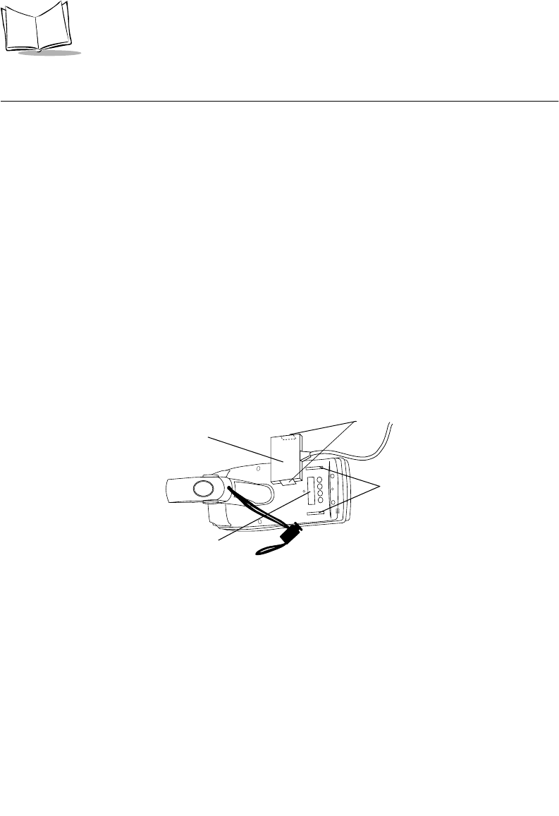
5-16
PDT 6800 Series Product Reference Guide
Running Communications
Communicating With a Host
To communicate with a host:
1. Set up the CCM 38/6860, CRD 38/6865 cradle, CRD 38/6866 cradle, or the PC
adapter as described in Chapter 2, Accessories Setup.
2. If using a cradle, place the terminal in the CCM or cradle.
3. Start the communications program on the host and terminal.
Communicating With a Printer
To communicate with a printer, attach the terminal to the Printer Interface Module (PIM):
1. Attach the PIM’s optical connector to the terminal’s optical port by inserting the clips
on the connector in the slots on either side of the port.
2. Plug the PIM’s DB-9 connector in the printer’s port.
3. Power the printer and terminal on.
Figure 5-7. Connecting the PIM to the PDT 6800 Series
Radio Communications
The PDT 6810 operates in a Symbol Spectrum One® RF network; the PDT 6840 Series
operates in a Symbol Spectrum24® RF network.
PIM
Optical Connector
Clips
Slots
Optical Port

5-17
Operating the PDT 6800 Series
The terminal’s Status LED indicates the state of the 6800’s connection to either of the RF
networks:
Refer to the network documentation for more information on operating the terminal in the
specific RF environment.
Off indicates that the radio is working and associated with an access
point (Spectrum24) or base station (Spectrum One).
Flashes red once per
second
indicates that the radio is out of range or not associated with an
access point or base station.

5-18
PDT 6800 Series Product Reference Guide

6-1
Chapter 6
Maintaining the Terminal
Batteries
The PDT 6800 Series terminal is powered by a rechargeable Nickel Cadmium (NiCd) or
Lithium Ion battery pack. Fully charged, the battery pack provides up to 8 hours of
continuous operation.
The NiCd battery pack is charged by:
!placing a terminal with the battery installed in a CCM 38/6860, CRD 38/6865, or
CRD 38/6866 cradle for 7 hours, or
!connecting the terminal to a PC Adapter, or
!placing the battery pack in a spare battery charging slot on the CCM 38/6860 or
CRD 38/6865 for up to 7 hours.
Note: The terminal can be used while the battery is being charged in the
CCM 38/6860 or connected to the PC Adapter.
The Lithium Ion battery pack p/n 21-40340-01 is charged by removing the battery from the
terminal and charging in a UBC 2000 battery adapter p/n 21-32665-24. Refer to the UBC
2000 Quick Reference Guide for more information.

6-2
PDT 6800 Series Product Reference Guide
Battery Life
Battery life is affected by many factors, including
!scanning
!radio communications
!very high or very low operating temperatures
!backlighting use
!battery age.
When to Replace or Recharge the Battery
The PDT 6800 Series terminals provide two types of indicators to notify you when battery
power is running low: warning messages and modified cursors. These indicators may be
changed or disabled by an application.
!LOW BATTERY - When the battery is low, the cursor changes as shown in Table 6-
1 on page 6-2. If ERR3000 is loaded, the message LOW BATTERY also appears. At
this level the terminal continues to operate, but there is probably less than 1 hour of
usable power left.
!VERY LOW - When the power is very low, the DEAD BATTERY message appears
and the system powers off. Replace or recharge the battery pack before attempting
to use the terminal. If the battery is not immediately recharged or replaced, data may
be lost.
Table 6-1. Cursor Indicators
Keyboard State Cursor Character
c
f
(inverted caret) (inverted solid caret)
(caret) (solid caret)
(up arrow) (solid up arrow)
(down arrow) (solid down arrow)
(underline c) (inverse c)
(underlined f) (inverse f)
Low Battery
Unshifted
Shifted
Momentary Shifted
Momentary Unshifted
Control
Function

6-3
Maintaining the Terminal
Backup Batteries
To prevent data loss during battery replacement, the terminal utilizes a super cap as a backup.
The super cap provides sufficient power to preserve memory contents for approximately 15
minutes while the primary battery is replaced. The super cap does not provide enough power
to operate the terminal. On receiving a low battery message, replace or recharge the primary
battery immediately.
Replacing the Battery Pack
Battery packs available from Symbol are listed below.
Note: The Series 3800 NiCd battery packs, 3872-103, 3872-105, and 3872-
115, CANNOT be used in the Series 6800 terminal.
Removing the Battery Pack
To remove the battery pack (Figure 6-1):
1. Power the terminal off.
2. Press the battery release buttons on both sides of the handle.
System P/N Battery Pack
NiCd Six-cell, 600 mAh IS 21-36474-01 Intrinsically safe rechargeable
in CCM 38/6860, CRD 38/
6865, CRD 38/6866, and PC
adapter
Lithium Ion 21-40340-01 Rechargeable in UBC 2000
battery adapter p/n 21-32665-
24
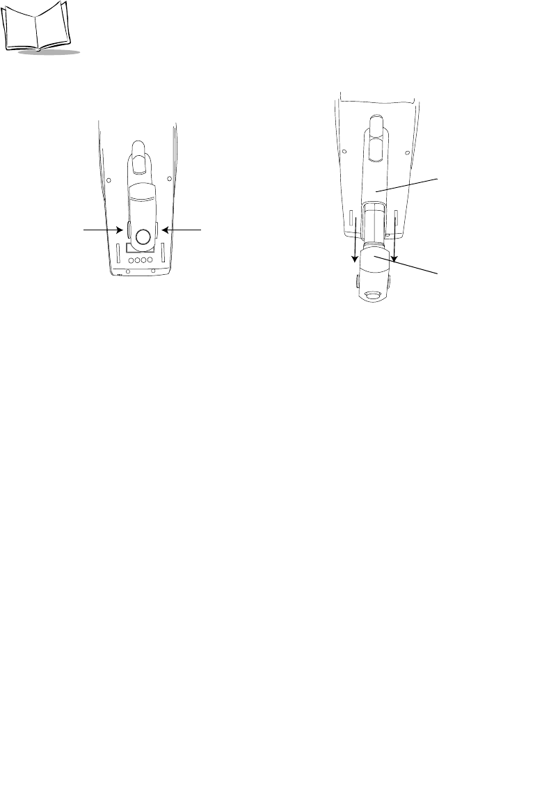
6-4
PDT 6800 Series Product Reference Guide
3. Slide the battery pack out of the handle.
Figure 6-1. Removing the Battery Pack
If you intend to store your terminal without the battery pack, ensure that you have stored any
data and/or programs you wish to keep on another terminal, a host computer, or another
medium to avoid loss of data. The terminal backup power source retains data for
approximately 15 minutes after the battery pack is removed, as long as the backup batteries
remain in place.
Installing the Battery Pack
1. Orient the battery pack with the handle facing the terminal’s scan window
(Figure 6-2).
2. Slide the pack into the battery compartment while pressing the battery release
buttons.
3. Press the battery lock in to secure.
Press
Release
Button
Press
Release
Button
Battery Compartment
Battery Pack
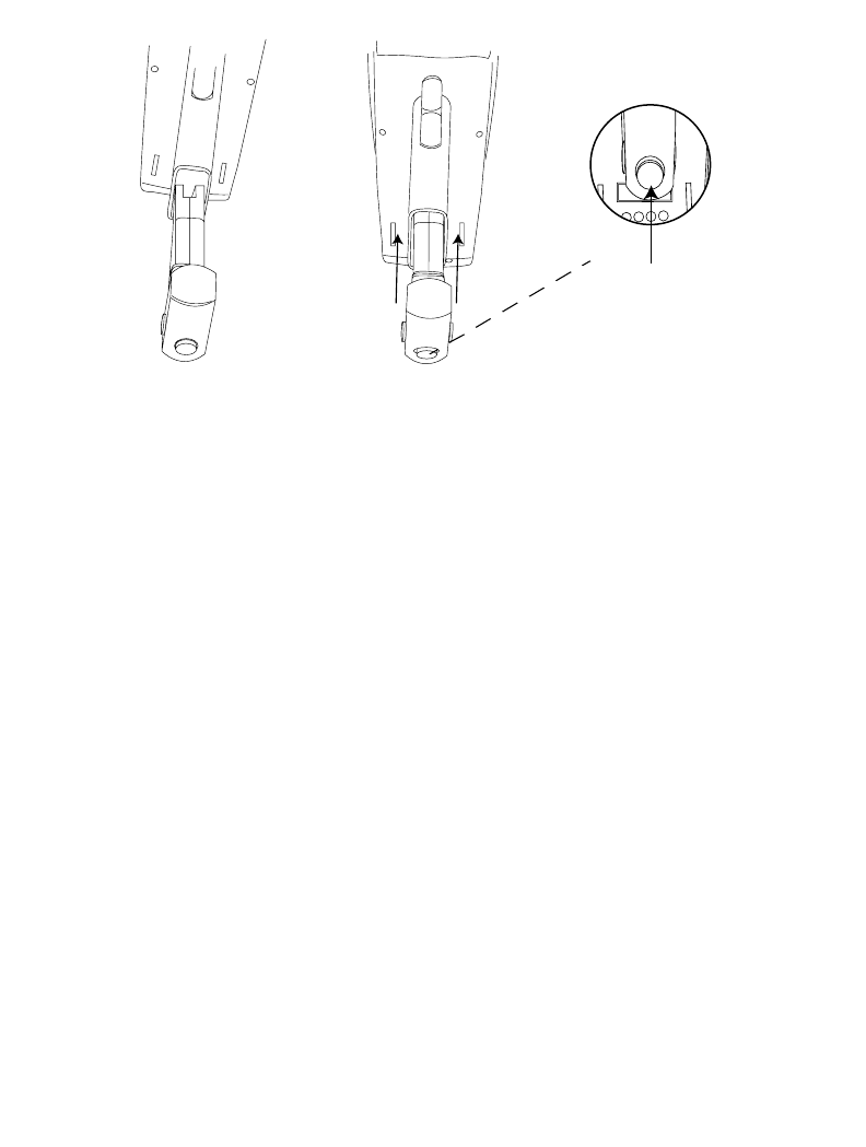
6-5
Maintaining the Terminal
Figure 6-2. Installing the Battery Pack
Battery Charging Tips
For maximum capacity and battery life, follow these helpful hints:
Do
!Charge at temperatures between 0°C and 38°C (32°F to 100°F); 21°C (70°F) is
preferred
!Recharge as soon as you see the “Low Battery” message
!Save your data and program on another terminal or another medium if you plan to
store your terminal without the primary battery pack
!Store batteries at room temperature of 21°C (70°F) or cooler
!Recharge the NiCd battery pack after storage.
Don't
!Store or recharge primary batteries at temperatures below 0°C (32°F) or above 38°C
(100°F)
!Judge a battery's charge level by measuring its voltage; voltage does not indicate
charge level.
Orient Slide
Push to
Lock
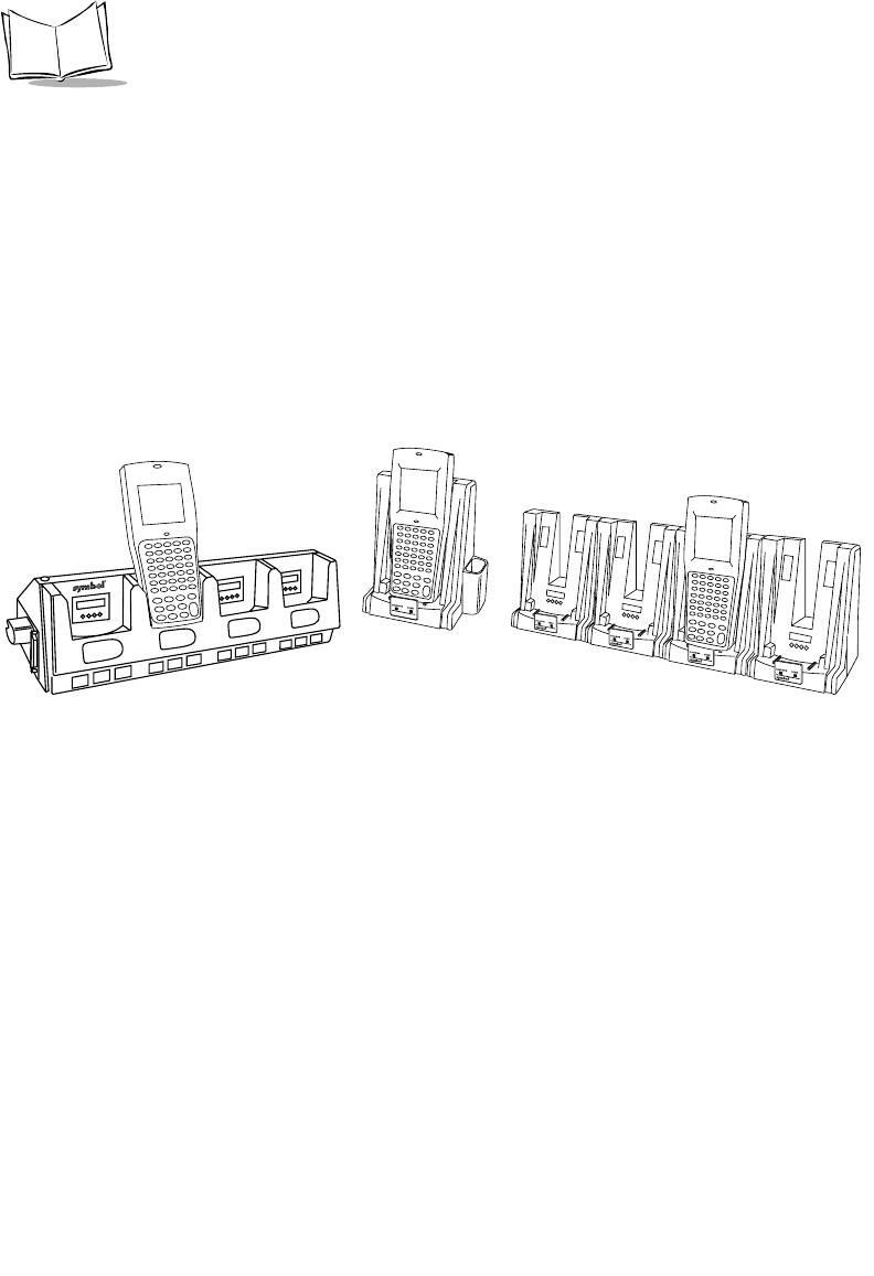
6-6
PDT 6800 Series Product Reference Guide
Charging the NiCd Battery Pack
The NiCd battery pack automatically charges when the terminal is placed in a cradle or
connected to a PC Adapter. A full charge takes about 7 hours. We recommend that you
always keep the NiCd battery pack fully charged.
Charging NiCd Battery pack in the Terminal Using a Cradle
To charge a NiCd battery in the terminal, using the CCM 38/6860, CRD 38/6865, or CRD
38/6866 cradle (Figure 6-3):
1. Place the terminal in the cradle. The cradle charging light flashes when charging a
discharged battery and remains steady when trickle-charging a charged battery.
Figure 6-3. Charging the Battery in the Cradle
2. Leave the terminal up to 7 hours to recharge a fully discharged battery.
Charging NiCd Battery Packs Outside the Terminal
Slots are provided in the CCM 38/6860 and CRD 38/6865 cradles to charge spare battery
packs outside the terminal.
Place the battery pack to be charged in one of the battery slots in the cradle. The LED
indicator lamp under the battery slot in which the terminal was placed indicates the battery
is charging. (On the CCM 38/6860, the spare-battery-charging indicator lamp is on the
right.) If the lamp is off, the battery pack is not charging. A blinking LED indicates fast
charge; a solid on LED means slow charge/ready. See the cradle documentation listed in
Related Publications on page x for details.
CCM 38/6860 CRD 38/6865 CRD 38/6866

6-7
Maintaining the Terminal
Caution
The optional communications cradles are NOT certified for use in potential-
ly hazardous environments. To charge an intrinsically safe PDT 6800 Series
terminal in a cradle, remove the terminal from the potentially hazardous en-
vironment before charging.
Battery Charging with the PC Adapter
Refer to Chapter 2, Accessories Setup, for instructions on setting up the PC Adapter for
charging.
Battery charging begins automatically when power is supplied to the PC Adapter. Fully
charging a battery using the PC Adapter requires 7 hours.
Other Charging Options
You have the option of charging battery packs in the UBC 1000 or 2000 Charger. Refer to
the documentation for the charger for more information.
Charging the Lithium Ion Battery Pack
Note: Placing the terminal in the cradle with a Lithium Ion battery installed
does not damage the battery.
The Lithium Ion battery does not charge when the terminal is placed in a cradle. Use the
cradle for communications and as a place holder for the terminal when a lithium Ion battery
is installed.
To charge the Lithium Ion battery p/n 21-40340-01, remove the battery from the terminal
and charge in a UBC 2000 battery adapter p/n 21-32665-24. Refer to the UBC 2000 Quick
Reference Guide for more information.
Cleaning
The PDT 6800 Series terminals require a minimum amount of maintenance. However, keep
the terminal clean to avoid problems and prolong the terminal’s life.
Before doing any maintenance or cleaning, power the terminal off.

6-8
PDT 6800 Series Product Reference Guide
To clean a terminal, use a clean, soft cloth dampened with a mild cleaner such as soap and
water. Do not use abrasive paper, cloth, or abrasive/corrosive cleaners.
Wipe the entire terminal, except for the scanner window, with the damp cloth. Clean the
charging contacts, keypad, and scanner trigger.
Wipe the scanner window periodically with a lens tissue or other material suitable for
cleaning optical material such as eyeglasses.
Do not pour, spray, or spill any liquid on any part of the terminal, particularly the scanner or
scan element components.
Storage
If the terminal will not be used for a while, store it in a cool, dry place, away from dust. For
the best protection, repack the terminal in the original shipping container for storage.
Caution
If you remove the primary battery, the terminal maintains memory contents
for at least 15 minutes. To prevent loss of programs and data, transmit them
to a host computer before removing the primary batteries for longer than 15
minutes.
When you remove the terminal from storage without the battery pack, reset the real time
clock. Refer to the Series 3000 Application Programmer’s Reference Manual or Series 3000
Application Programmer’s Guide for specific instructions.

7-1
Chapter 7
Error Recovery and Troubleshooting
Introduction
This chapter provides information to assist in basic troubleshooting analysis and correction,
including:
!Error messages
!Troubleshooting start-up failures
!Troubleshooting Spectrum24 terminal initialization failures
!Running the Self Test function
!Self Test summaries
!Keyboard test
!Running memory transfer.
!Scanning problems

7-2
PDT 6800 Series Product Reference Guide
Error Messages
If ERR3000 is loaded in the system configuration, the terminal displays the following
messages to indicate error conditions that affect system performance. A message is usually
accompanied by one or more beeps, after which the system returns to its previous status.
The application can change the actual wording of the messages or disable messages. The
messages listed in Table 7-1 are representative. Refer to the Series 3000 Application
Programmer's Guide or your application guide for additional information.
Table 7-1. Error Messages
Message Explanation
Double Key Error Two or more keys were pressed at the same time. This does not
include boot sequences described in Chapter 5, Operating the
PDT 6800 Series.
Low Battery The battery pack should be recharged or replaced as soon as
possible.
Dead Battery Replace or recharge the battery pack immediately. This message
is programmable, so it may be worded differently. See your
application guide. After this message is displayed, the terminal
shuts itself off. You may not be able to power it on again until
the battery pack is charged.
Power Fault The last terminal power off was caused by a power failure.
Possible causes of a power failure include:
•the battery pack is removed with the terminal on
•the terminal is dropped
•the batteries lose power suddenly
•the terminal displays a low battery power error message, and
you attempt to power the terminal on without recharging or
replacing the batteries.

7-3
Error Recovery and Troubleshooting
Troubleshooting
Table 7-2 lists some minor problems, causes, and actions to take. If you cannot resolve the
problem after checking this list, call the Symbol Support Center for assistance.
Startup Failure
Problems are most frequently start-up failures. If cold booting the terminal does not start the
application successfully, the application, the system software, or the system is
malfunctioning. If you can boot the system to Command Mode, try the following:
!Use Program Loader to download a new version of the software to NVM. This
procedure is described in Chapter 3, Batch and Spectrum One Terminal Setup or
Chapter 4, Spectrum24 RF Terminal Setup. After downloading new software, warm
boot the terminal as described in Chapter 5, Operating the PDT 6800 Series.
!Use Self Test to check whether system hardware is operational. The Self Test
procedure is described later in this chapter. After downloading new software, warm
boot the terminal as described in Chapter 5, Operating the PDT 6800 Series.
Boot Failure Messages
During a cold boot, the system briefly displays a status line for each driver as it loads, in the
format
0:Driver #.##
The line shows a status value, usually 0, followed by the name and version number of the
driver. If the system halts at one of these lines and displays a status value other than 0, the
displayed driver did not load properly.
Table 7-2. Troubleshooting the Terminal
Symptom Possible Cause Action
Display is blank. Battery pack is dead or
missing.
Replace or recharge battery
pack.
Terminal does not respond
when keys are pressed.
Application program was not
successfully downloaded.
Repeat downloading.
Time and date are incorrect. Real-time clock has
malfunctioned or needs
setting.
Set time and date. See your
application guide.

7-4
PDT 6800 Series Product Reference Guide
If such a failure occurs, cold boot the terminal again. If this does not solve the problem, call
Symbol Customer Support.
More troubleshooting information is found in the documentation listed in Related
Publications.
Spectrum24 Terminal
Typical initialization and operating problems and solutions for Spectrum24 terminals are
listed in Table 7-3.
Table 7-3. Troubleshooting Spectrum24 Terminal s
Problem Explanation/Action
Out of range Terminal is out of the Access Point’s range.
If you move the terminal during initialization, the
terminal may be out of range of the AP and unable to
complete the initialization process.
Move back in range and repeat the initialization process.
Startup process fails Boot server type (BOOTP or DHCP) doesn’t exist.
Verify that the boot server is operating and able to
respond to TCP/IP, BOOTP, or DHCP requests from the
terminal.
Low battery message Place the terminal in a cradle and recharge battery.
OR
Power terminal off and replace battery.
Battery is dead Battery not replaced after receiving low battery message
or terminal left on for more than 24 hours.
Recharge or replace the battery.
Terminal disassociated from
Access Point
Application does not respond to interactive operations.
Applications using internal batch mode continue to
function until required to transmit via radio, then fail to
work. No message displayed.

7-5
Error Recovery and Troubleshooting
Self Test Function
Command mode includes a Self Test function which verifies that terminal hardware
components are operating properly. Components tested include:
!Real-time clock (RTC)
!Battery power
!Keyboard codes
!Liquid crystal display (LCD) controller
!Read-only memory (ROM), random-access memory (RAM), expanded memory
(EMS), and non-volatile memory (NVM).
Run Self Test if you suspect a problem with the hardware. Except for keyboard testing, no
operator input is necessary after selecting a test screen.
Running Self Test
Access the Self Test function from the Command Mode Menu:
1. Boot to Command Mode (refer to Chapter 5, Operating the PDT 6800 Series for
boot sequence).
2. In the Command Mode Main Menu, use the UpArrow or DownArrow to scroll
through the options.
3. Highlight Self Test and press <Enter>.
Press <CLR> in any Self Test screen to return to the Self Test screen, or from the Self Test
screen to return to the Command Mode screen.

7-6
PDT 6800 Series Product Reference Guide
Self Test Summaries
Self test is divided into five functions or screens:
Config Screen 1 - Reports the terminal series, BIOS version, battery status, and current
power source.
Config Screen 2 - Reports information on the keyboard and display, including power
wakeup source.
Memory Screen - Tests ROM, RAM, and EMS (Expanded) memory, and reports the
amount of installed RAM and EMS.
Fill Screen - Fills the entire screen with a test pattern to verify that the entire screen
displays.
Set RTC Screen - Sets the time and date settings of the real-time clock.
Keyboard Test
Keyboard testing can be performed while the terminal displays Config Screen 1 results.
Test any keys except <CLEAR> and <PWR>. When you press a key, the corresponding key
code is displayed on the top row to the right of the test name. Table 7-4 lists the codes for the
35-key keyboard and Table 7-5 lists the codes for the 46-key keyboard.

7-7
Error Recovery and Troubleshooting
Table 7-4. 35-Key Keyboard Test Code s
Key Test Code Key Test Code
SPACE 00 L 19
ALPHA 01 M 20
CTRL 02 N 21
FUNC 03 O 22
BKSP 04 P 23
SHIFT 07 Q 24
A08R25
B09S26
C10T27
=11U28
E12V29
F13W30
G14X31
H15Y32
I16Z33
J17ENTER34
K18

7-8
PDT 6800 Series Product Reference Guide
If numbers other than those given in the tables appear on the display, please contact your
authorized representative. Press <CLEAR> to terminate the test and return to the Self Test
screen.
Memory Transfer Program
Command Mode includes a memory transfer utility that transfers data from a terminal to a
host PC for program troubleshooting. Programmers can analyze an application using tools
provided in the Series 3000 Application Development Kit and described in the Series 3000
Application Programmer’s Reference Manual.
Hardware Setup
1. Turn off the terminal and host PC. Disconnect or unplug the cradle, if used.
Table 7-5. 46-Key Keyboard Test Codes
Key Test Code Key Test Code Key Test Code
FUNC 01 M 17 Period 32
SHF 02 N 18 Up arrow 33
CTL 03 0 19 Down arrow 34
A05P20735
B06Q21836
C07R22937
D08 S 23 438
E09T24539
F10U25640
G11V26141
H12W27 2 42
I13X28343
J14Y29044
K15Z30ENTER45
L16BKSP31
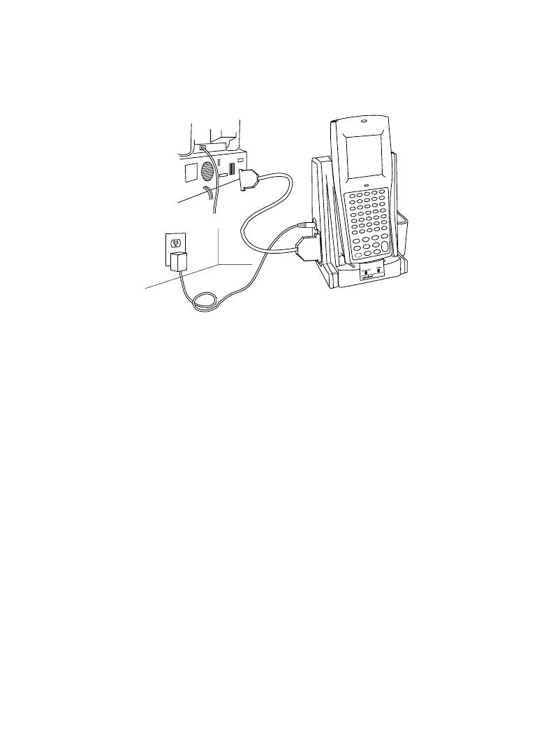
7-9
Error Recovery and Troubleshooting
Caution
Always power off the terminal before attaching or removing cables and
adapters.
2. Connect an RS-232 null modem cable to the PC's serial port.
Figure 7-1. Memory Transfer Connections
3. Connect the other end of the cable to the cradle’s communication port.
4. Connect the cradle to a power source.
5. Place the terminal in the cradle.
6. Power on the host PC.
Set Communications Parameters
Host
1. Start the communications program on the host PC.
2. Set up the host communication parameters (these parameters must match the
terminal’s parameters). At the DOS prompt on the host, enter:
RCVHEX <filename.hex> <baud rate> <comport#>
Typical parameters are:
38400 bps Odd parity
7 bit data Xon/Xoff flow control

7-10
PDT 6800 Series Product Reference Guide
Te r m i n a l
1. Boot the terminal to Command Mode (refer to Chapter 5, Operating the PDT 6800
Series for the appropriate key sequence).
2. Select the Memory Transfer function from the Command Mode menu. Use UpArrow
or DownArrow to scroll through the Command Mode options until Memory
Transfer is displayed, then press <ENTER>.
3. Select the range of memory to transfer by pressing the first letter of the desired range
(All, Range, or None), or use the UpArrow or DownArrow and press <ENTER>.
If you select All, the program skips to the range verification screen (step 7, page 10).
If you select Range, the screen displays:
RAM
Use Arrow Keys
Start End
00000 9FFFF
4. Specify a range of RAM by setting the Start and End addresses.
"Use RightArrow and LeftArrow to move the cursor to the digit to be changed
"Use UpArrow and DownArrow to change the values.
Type a range and press <ENTER>.
5. Specify a range of NVM to transfer. Choose All or None.
6. If the system has EMS installed, it prompts for the range to transfer; otherwise, it
skips this screen:
EMS
Use arrow keys
Start End
The range is specified in page numbers (16 KB per page). Use RightArrow and
LeftArrow to move between the Start and End values. Use UpArrow and
DownArrow to change the page number value.
Set the range and press <ENTER>.
7. The terminal displays a range verification screen. For example:
RAM 0000 3FFF
NVM D510 DFFF

7-11
Error Recovery and Troubleshooting
EMS 0000 010
Correct? <ENT>
If the values are correct, press <ENTER>. If the values are not correct, press
<CLEAR> to clear the fields and select new values.
8. Specify the baud rate. Use the UpArrow and DownArrow to scroll through the list
of baud rates until the correct rate is displayed and press <ENTER>.
Note: Flow control may be necessary at 38400 bps and higher.
9. Specify the data bits. Press <7> or <8>, or use UpArrow and DownArrow to display
the values 7 or 8, and press <ENTER>.
Note: If you select 8 data bits, the program selects No parity and skips the
next screen.
10. Specify parity type. Use UpArrow and DownArrow to display a parity option, or
press the first letter of a parity option (Even, Odd, None, Space, or Mark) and press
<ENTER>.
11. Set flow control. Use UpArrow and DownArrow to display the flow control options,
or press the first letter of an option (None, Xon/Xoff, or RTS/CTS) and press
<ENTER>.
Start Communications
1. The terminal is ready to send the data to the host PC and displays:
Comm Parameters
Start? <ENT>
2. Verify that the host is ready to receive data.
3. Press <ENTER> on the terminal.
While data is being transferred, the terminal displays a report of the 1 KB range being
transferred:
Memory Transfer
Sending: XXXX

7-12
PDT 6800 Series Product Reference Guide
The display is updated for every 1024 bytes (1 KB) of memory.
4. When the transmission completes or aborts, the terminal displays the transmission
status screen:
Memory Transfer
Status 0000
A status of 0000 (all zeros) indicates that the transfer was successful. Any other
status indicates failure. Refer to Appendix C, Communications Status Codes, for the
status codes which indicate the source of the error.
End Communications
To return to the Command Mode Main Menu, press <CLEAR>. Take whatever corrective
action is necessary and reboot the terminal.
Internal Modem Problems
If you are having difficulties with your internal modem, please check the following before
returning your product:
!Connection to the telephone network is correct.
!Any necessary special requirements such as dialing 9 and ignoring dial tone have
been considered in the event of using a PBX.
!Firmware settings described in the Series 3000 Application Programmer’s Guide have
been configured correctly.
Scanning Problems
What If...
Nothing happens when you follow the operating instructions?
!Check the system power.
!Verify that the scanner is programmed to read the symbology you are trying to read.
!Try scanning a test symbol of the symbology you are trying to read.
!Check the bar code to ensure that it is not defaced. A defaced bar code may not be
readable.

7-13
Error Recovery and Troubleshooting
!Check to see that you are scanning from the proper distance.
Your terminal operates but scanned data is not displayed correctly?
!Check the system power.
!Check that the communications parameters (baud rate, parity, stop bits, etc.) are set
properly for the receiving device.
The laser does not activate?
!You may have exceeded the allowable amount of scanning activity within the limits
of your laser class of operation; in this case, wait for a short interval before scanning
again.
!You may be scanning in an inappropriately hot environment. If so, remove the
equipment from the environment or allow the laser to cool down.

7-14
PDT 6800 Series Product Reference Guide


B-1
Appendix B
Keyboard Layouts
Introduction
The following pages show the characters and character sequences produced by the 35-
key and 46-key PDT 6800 Series keyboard when modified with the key sequence in the
figure caption. For instance, Figure B-4 shows what characters the keys produce when
you press the Alpha key first.
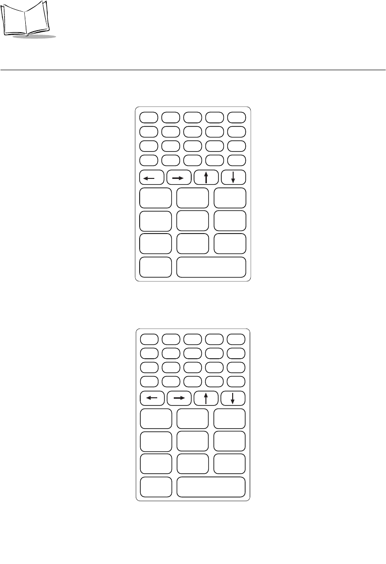
B-2
PDT 6800 Series Product Reference Guide
35-Key Keyboard
Key definitions can be changed by the application program. The captions indicate what
sequence of modifier keys produce the keyboard.
Figure B-1. 35-Key PDT 6800 Series Keyboard
Figure B-2. 35-Key Unmodified Keyboard
ENTER
0
Z
123
6
9
8
5
7
4
F10
W
T
QR
U
XY
V
S
FUNC ALPHA CLEAR SHIFT PWR
BKSP SPACE CTRL [ A ] B
' C = D * E / F - G
+ H . I , J \ K ; L
MNO P
F1 F2 F3
F6F5F4
F9F8F7
ENTER
0
123
6
9
8
5
7
4
FUNC ALPHA CLEAR SHIFT PWR
BKSP SPACE CTRL [ ]
' = * /
-
+ . , \ ;
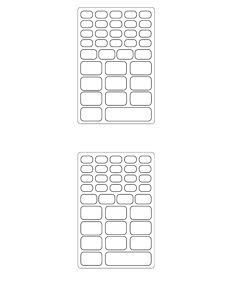
B-3
Keyboard Layouts
Figure B-3. 35-Key Function Key Modified Keyboard
Figure B-4. 35-Key Alpha Key Modified Keyboard
ENTER
F10
F1 F2 F3
F6
F9F8
F5
F7
F4
FUNC PWR
'=*/-
+\
\
DARKER
SCREEN LIGHTER
SCREEN
BACK-
LIGHT
ENTER
Z
WXY
V
S
R
U
Q
T
ALPHA PWR
AB
CDEFG
HIJ
K L
MNOP
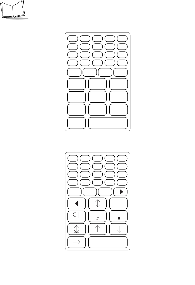
B-4
PDT 6800 Series Product Reference Guide
Figure B-5. 35-Key Shift Key Modified Keyboard
Figure B-6. 35-Key Control (CTRL) Key Modified Keyboard
ENTER
)
!@#
^
(
*
%
&
$
SHIFT PWR
{}
"+?_
+>< :
|
4682
ENTER
PWR
CTRL
!!
u
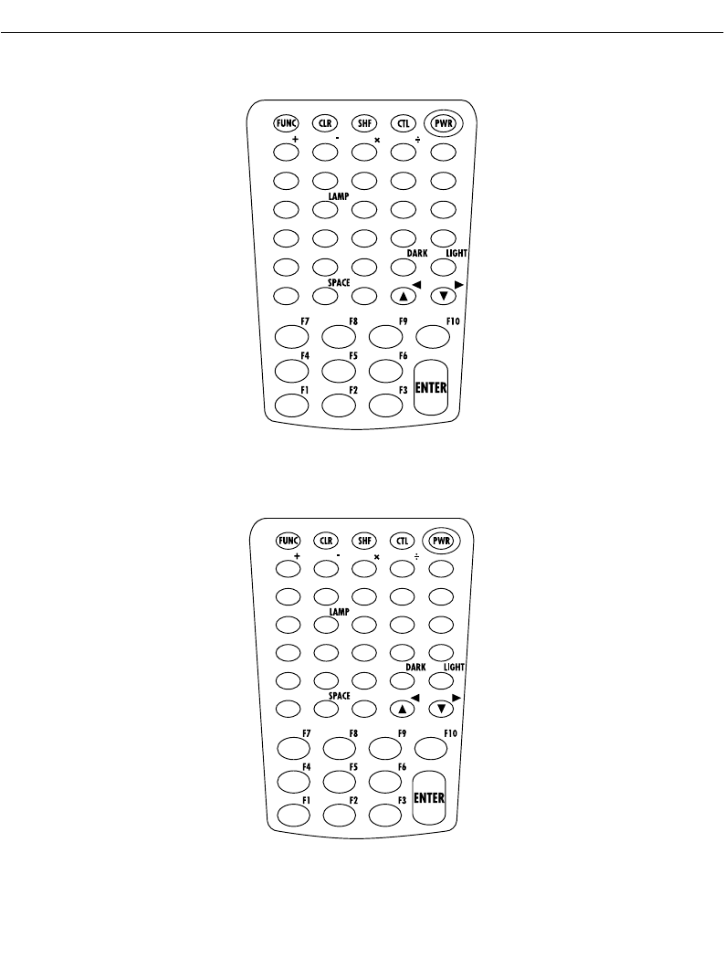
B-5
Keyboard Layouts
46-Key Keyboard
Key definitions can be changed by the application program. The captions indicate what
sequence of modifier keys produce the keyboard.
Figure B-7. 46-Key PDT 6800 Series Keyboard
Figure B-8. 46-Key Unmodified Keyboard
=
BKSP .
7890
456
123
ABCDE
FGH IJ
KLMNO
PQRST
UVWX Y
Z
=
abcde
fghi j
klmno
pqrst
uvwx y
zBKSP .
7890
456
123
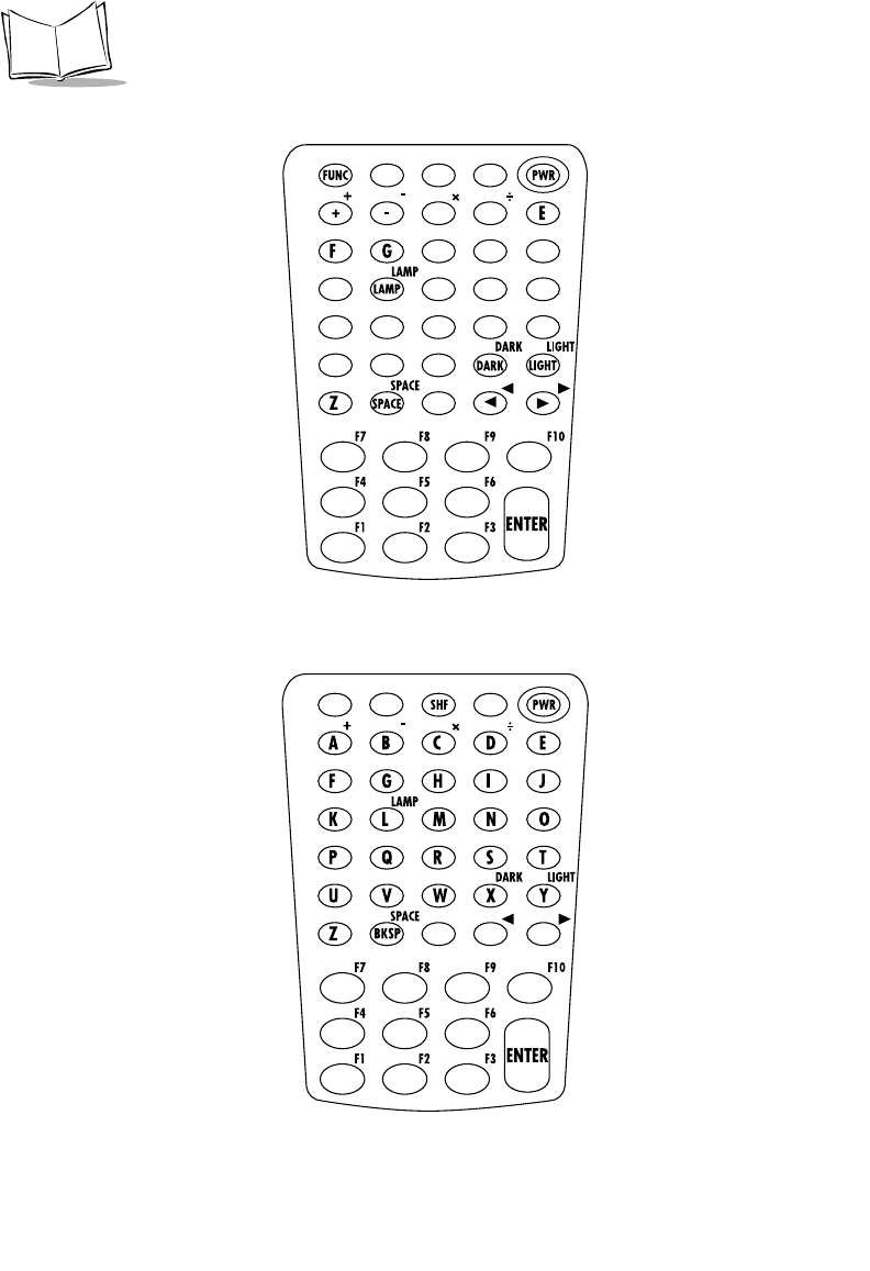
B-6
PDT 6800 Series Product Reference Guide
Figure B-9. 46-Key Function Key Modified Keyboard
Figure B-10. 46-Key Shift Key Modified Keyboard
=
*/
',/
\=\
-[];
F7 F8 F9 F10
F4 F5 F6
F1 F2 F3
=
>82
&*()
$%^
!@#
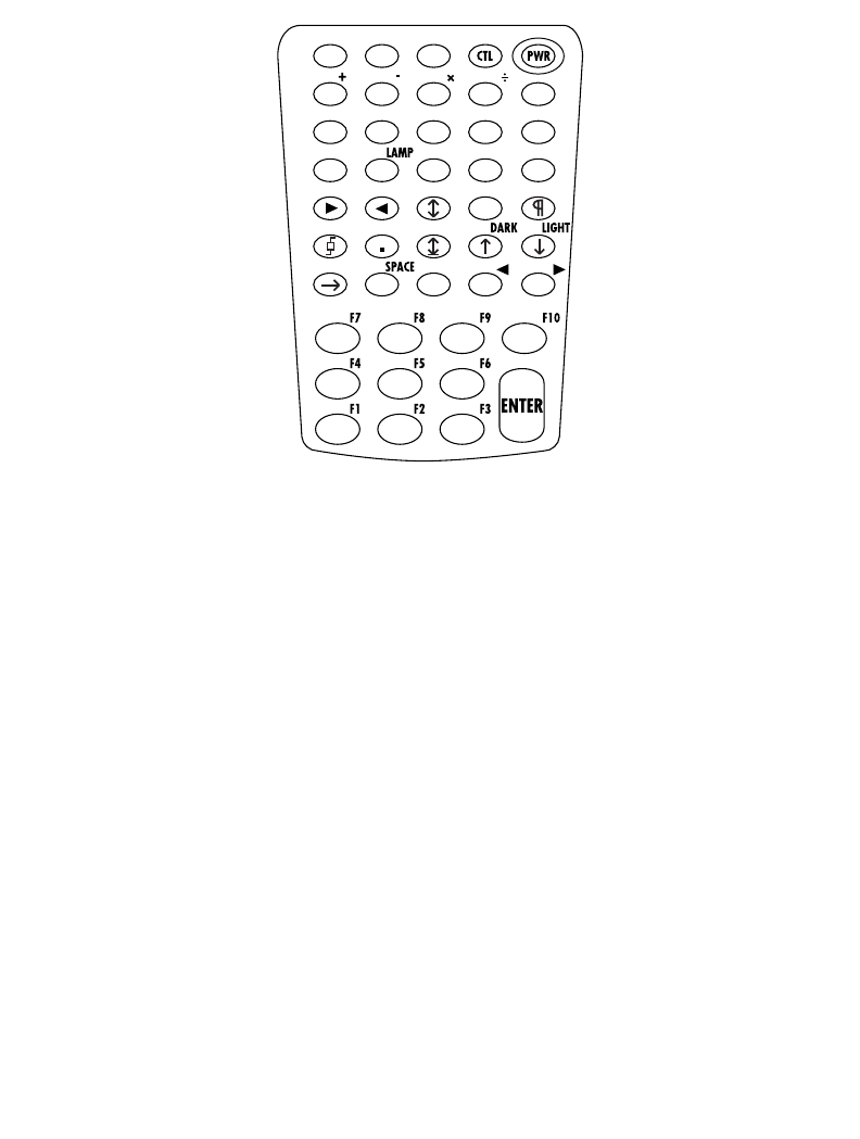
B-7
Keyboard Layouts
Figure B-11. 46-Key Control (CTL) Key Modified Keyboard
=
u
[ ]
!!

B-8
PDT 6800 Series Product Reference Guide

C-1
Appendix C
Communications Status Codes
Introduction
The program loader status code consists of four hexadecimal digits which indicate whether
or not the transfer was successful, and if not, the source of the communications error. A status
code of 0000 indicates success; any other code indicates failure.
Tab l e C- 1 lists the failures associated with the status codes. The values are additive.

C-2
PDT 6800 Series Product Reference Guide
Table C-1. Communications Status Codes
Status Code Meaning
0002 Receive overrun error
0004 Receive parity error
0008 Receive framing error
0010 Programming voltage not present
0020 Data Set Ready or Carrier Detect not
detected on open
0040 Lost DSR while receiving
0080 ABORT key hit during comm
0100 Insufficient NVM for image
0200 Illegal Intel hexadecimal record
0400 Unsupported Intel record
0600 NVM EEPROM failed to erase
0800 Receive time-out error
1000 Control start character time-out
2000 Clear To Send inactive time-out error
4000 Receive buffer full

D-1
Appendix D
Specifications
Environment
The terminal’s operating conditions are listed in Tabl e D-1 .
Table D-1. Environmental Specifications
Note: Batteries lose power faster at extremely high and low temperatures.
The LCD operates slowly at temperatures below 0oC.
Condition Range
Operating Temperature -13°F to 122°F (-20°C to 50°C)
Storage Temperature -13°F to 140°F (-20°C to 60°C)
Humidity (Operating) 95% relative humidity, noncondensing
Altitude Up to 10,000 feet
Electrostatic Up to 15 KV discharge to all surfaces (terminal
power may go off)
Shock Withstands multiple 4-foot drops to concrete
without malfunction or loss of data

D-2
PDT 6800 Series Product Reference Guide
RF Communications
Specification Spectrum One
(6810)
Spectrum24
(6842, 6845)
Spectrum24
(6846)
Spreading
Technique
Direct sequence Frequency hopping Frequency hopping
Data Rate 60.6 Kbps 1 Mbps/2 Mbps 11 Mbps
Range:
Open Space 1500 feet/454 meters Up to 1000 feet/303 meters Up to 1000 feet/303 meters
Frequency
Range
902-928 MHz Country dependent.
Typically 2.4 to 2.5 GHz
Country dependent.
Typically 2.4 to 2.5 GHz
Output Power 250 mW 500 mW (US)
100 mW (International)
500 mW (US)
100 mW (International)
Ethernet
Compatibility
Through NCU Dix Ethernet Dix Ethernet
Radio Channel
Access Method
CSMA/CA CSMA/CA CSMA/CA
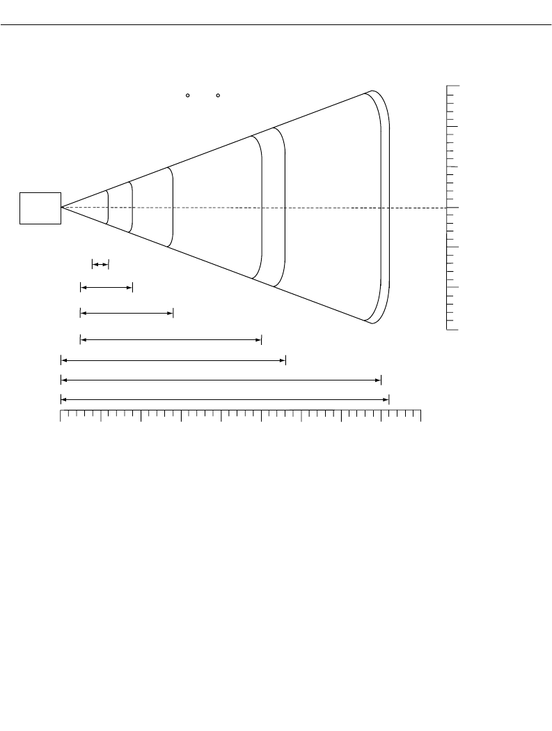
D-3
Specifications
Scanning Decode Zones
Figure D-1. 1D Scanning Decode Zones
In.
cm 0
05
12.7 10
25.4 15
38.1 20
50.8 25
63.5 30
76.2 35
88.9
Minimum distance determined by symbol length and scan angle
0
5
10
15
5
10
In. cm
W
i
d
t
h
o
f
F
i
e
l
d
Depth of Field
Note: Typical performance at 68 F (20 C)
on high quality symbols.
40
101.6 45
114.3
15
5 mil
6.0
4.0
7.5 mil 9.0
2.5
SE 1200
STANDARD
10 mil 14.0
2.5
15 mil 25.0
2.5
20 mil 28.0
*
*
40 mil 40.0
*55 mil 41.0
*
0
12.7
25.4
38.1
12.7
25.4
38.1

D-4
PDT 6800 Series Product Reference Guide

E-1
Appendix E
Boot-Up Quick Reference
Introduction
Tab l e E-1 and Ta ble E- 2 list the boot procedures for the 35 and 46-key keyboards.
Table E-1. 35-Key Boot Procedures
Boot Type Key Sequence Used For Results
Power On PWR, or Trigger, or
remove terminal
from cradle
Applying power Returns terminal to where it was when
it was turned off.
Warm Boot <F>
<J>
<PWR>
Choosing a
program that
resides in NVM.
If system software is present, returns
terminal to DOS. Otherwise, returns
terminal to command mode. Retains
contents of RAM.
Cold Boot <SPACE>
<FUNC>
Up Arrow
<PWR>
Resetting BIOS and
the operating
system.
Erases and recreates RAM disk. Only
data in NVM is retained.
Command
Mode Start
<BKSP>
<SHIFT>
<PWR>
Entering command
mode for Self Test
or communication
Takes terminal to beginning of
command mode. The first time you
turn the terminal on or after the
terminal has been stored without
batteries, acts the same as a Cold Boot
(resets BIOS, loses contents of RAM).

E-2
PDT 6800 Series Product Reference Guide
Table E-2. 46-Key Boot Procedures
Boot Type Key Sequence Used For Results
Power On PWR, or Trigger, or
remove terminal
from cradle
Applying power Returns terminal to where it was when
it was turned off.
Warm Boot <4>
<5>
<PWR>
Choosing a
program that
resides in NVM.
If system software is present, returns
terminal to DOS. Otherwise, returns
terminal to command mode. Retains
contents of RAM.
Cold Boot <A>
<B>
<D>
<PWR>
Resetting BIOS and
the operating
system.
Erases and recreates RAM disk. Only
data in NVM is retained.
Command
Mode Start
<F>
<I>
<PWR>
Entering command
mode for Self Test
or communication
Takes terminal to beginning of
command mode. The first time you
turn the terminal on or after the
terminal has been stored without
batteries, acts the same as a Cold Boot
(resets BIOS, loses contents of RAM).

F-1
Appendix F
2D Scanner Drivers and Applications
Introduction
The PDT 6800 Series terminal uses additional scanner drivers and applications to scan 2D
bar codes. This chapter covers the following:
!Using scn2dssi.exe
!Output messages
!Application development
!Application Notes
!New APIs
!New API definitions
!Label Type definition for 2D scanner driver
!SCN2DSSI scanner driver default parameters
!Using bldscn2D.exe
!Code type menus
!Parameter menus.
Using Scn2dssi.exe
Usage
!Scn2dssi.exe: Load the driver
!Scn2dssi.exe -o: Overwrite the previous driver

F-2
PDT 6800 Series Product Reference Guide
!Scn2dssi.exe -r: Remove the current driver
Output Messages
Application Development
The driver works with the standard Serial 3000 applications such as scan.exe. To use new
APIs (ioctl functions), the urm.gt and urm.gd files must be updated.
Table F-1. Output Messages
Screen Description
0:NB2DSSIA 1.03
PDF DRIVER LOADED
CRC Checksum:0x1949
NEW INTB6 INSTALLED
decoder: NBRWCAAE
|||||||||||||
The driver is successfully loaded. The driver version
string is NB2DSSIA; major revision 1.0, minor
revision 0.3. The checksum is 0x1949 (checksum
will be different based on the version number) with
decoder version string of NBRWCAAE.
0:NB2DSSIA 1.03
PDF DRIVER LOADED
CRC Checksum:0x1949
Re-Install Driver
NEW INTB6 INSTALLED
decoder: NBRWCAAE
|||||||||||||
The driver is successfully loaded. The driver version
string is NB2DSSIA; major revision 1.0, minor
revision 0.3. The checksum is 0x1949 (checksum
will be different based on the version number) with
decoder version string of NBRWCAAE.
0:NB2DSSIA 1.03
PDF DRIVER LOADED
CRC Checksum:0x1949
NEW INTB6 REMOVED
Driver Removed
The driver is successfully loaded. The driver version
string is NB2DSSIA; major revision 1.0, minor
revision 0.3. The checksum is 0x1949 (checksum
will be different based on the version number).

F-3
2D Scanner Drivers and Applications
Application Notes
With composite codes enabled, you will experience a delay decoding UPC/EAN bar codes.
New APIs
Tab l e F-2 lists new APIs for scn2dssi.exe. Refer to scan1d2d.c for information on how to use
these functions.
Table F-2. APIs
Function Length Structure
ConsIoctlGetExtDecoders (0x1B)
ConsIoctlSetExtDecoders (0x19)
ConsIoctlGetExtDecodersLen
ConsIoctlSetExtDecodersLen
struct ExtDecoders_S
{
BYTE Bookland;
BYTE EAN128;
BYTE ISBT128;
BYTE CouponCode;
BYTE C39Trioptic;
BYTE TLC39;
BYTE RSS_14;
BYTE RSS_Limited;
BYTE RSS_Expanded;
BYTE CompositeAB; +
BYTE CompositeC; +
BYTE
Code128_Emulation; *
BYTE MicroPDF;
};

F-4
PDT 6800 Series Product Reference Guide
ConsIoctlGetExtDecoderParms (0x1C)
ConsIoctlSetExtDecoderParms (0x1A)
ConsIoctlGetExtDecoderParms
Len
ConsIoctlSetExtDecoderParms
Len
struct ExtDecoderParms_S
{
BYTE linear_security_level;
BYTE
linear_supp_enabled;BYTE
code39_xmit_chkdgt;
BYTE xmit_i25_chkdgt;
BYTE msi_chkdgt_scheme;
BYTE check_i25_chkdgt;
BYTE
random_weight_chkdgt;
BYTE tri39_red_enabled;
BYTE
cvtEAN8_2_EAN13;
BYTE cvtI25_2_EAN13;
BYTE cvtC39_2_C32;
BYTE C32Prefix;
BYTE EnableC128Perf;
BYTE C128PerfLvl;
BYTE EnableC39Perf;
BYTE C39PerfLvl;
BYTE updf_performance;
BYTE UPC_Composite;
};
ConsIoctlGetScanOptions (0x1D)
ConsIoctlSetScanOptions (0x1B)
ConsIoctlGetScanOptionsLen
ConsIoctlSetScanOptionsLen
struct ScanOptions_S
{
BYTE laser_on_time;
BYTE aim_time;
BYTE scan_mode;
BYTE aim_mode;
};
Table F-2. APIs (Continued)
Function Length Structure

F-5
2D Scanner Drivers and Applications
ConsIoctlGetMacroPDF 0x1C
ConsIoctlSetMacroPDF 0x1A
ConsIoctlGetMacroPDFLen
ConsIoctlSetMacroPDFLen
struct MacroPDF_S
{
byte xmit_file_name;
byte xmit_block_count;
byte xmit_time_stamp;
byte xmit_sender;
byte xmit_addressee;
byte xmit_csum;
byte xmit_file_size;
byte xmit_header;
byte xmit_marker;
};
ConsIoctlGetMacroPDFAuxData (0x1E) ConsIoctlGetMacroPDFAuxDa
taLen
struct
MacroPDFAuxData_S
{
WORD SegmentIndex;
WORD SegmentCount;
CHAR FileId[256];
time_t Time_stamp;
WORD FileSize;
WORD CheckSum;
CHAR FileName[256];
CHAR Sender[256];
CHAR Addressee[256];
}; ++
ConsIoctlGetVersion (0x1F) ConsIoctlGetVersionLen struct Version_S
{
BYTE Major;
BYTE Minor;
BYTE Scannerver[20];
BYTE Decoderver[20];
};
Table F-2. APIs (Continued)
Function Length Structure

F-6
PDT 6800 Series Product Reference Guide
New API Definitions
Get/Set Extended Decoders
ConsIoctlGetExtDecoders command returns the status of the additional supported decoders
in the terminal and uses ConsIoctlSetExtDecoders command to enable or disable the
additional decoders supported in the terminal.
ConsIoctlGetMultiPacketStatus (0x20) ConsIoctlGetMultiPacketStatus
Len
struct MultiPacketStatus_S
{
BYTE NumPacketsLeft;
};
* Code128 Emulation is not supported in current release, but will be supported in future releases.
+ When Composite AB/C is enabled, the following barcode types are automatically enabled regardless of
their status (EAN-128, EAN-13, EAN-8, RSS Expanded, RSS Limited, RSS-14, UPC-A, and UPCE). If
driver-enabled barcode type is scanned, the driver WILL NOT send the data to application.
++ For MacroPDF, the driver returns MacroPDF barcode type to the application along with the main
block. An application can then call ConsIoctlGetMacroPDFAuxData to retrieve the control block
information. MacroPDFAuxData structure contains the last scanned and decoded MacroPDF control
block. If MacroPDF has never been scanned, the field will contain 0, or NULL.
Table F-3. Get/Set Extended Decoders
Field Size Value/Description
Subcommand Number BYTE 27 = Get, 25 = Set
Error Code BYTE Not Used
Bookland* BYTE 0 = Disable, 1 = Enable
EAN128 BYTE 0 = Disable, 1 = Enable
ISBT128 BYTE 0 = Disable, 1 = Enable
CouponCode* * BYTE 0 = Disable, 1 = Enable
C39Trioptic *** BYTE 0 = Disable, 1 = Enable
TLC39 BYTE 0 = Disable, 1 = Enable
RSS_14 BYTE 0 = Disable, 1 = Enable
Table F-2. APIs (Continued)
Function Length Structure

F-7
2D Scanner Drivers and Applications
Get/Set Extended Decoder Parameters
Uses ConsIoctlGetExtDecoderParms or ConsIoctlSetExtDecoderParms to get or set the
extended parameters.
RSS_Limited BYTE 0 = Disable, 1 = Enable
RSS_Expanded BYTE 0 = Disable, 1 = Enable
CompositeAB +BYTE 0 = Disable, 1 = Enable
CompositeC +BYTE 0 = Disable, 1 = Enable
Code128_Emulation ++ BYTE 0 = Disable, 1 = Enable
MicroPDF BYTE 0 = Disable, 1 = Enable
* Bookland: User must enable UPC-A and/or EAN13 for Bookland.
** CouponCode: When enabled, it decodes UPC-A, UPC-A with 2 supplemental, UPC-A
with 5 supplemental, and UPC-A/EAN-128 barcode codes. User must enable UPC-A,
EAN-13, and EAN-128.
***C39Trioptic: Trioptic Code39 symbols always contain six characters. Trioptic Code39
and Code39 Full ASCII cannot be enabled simultaneously.
+ Composite AB: When enabled, the following barcode types are automatically enabled
regardless of their status (EAN-128, EAN-13, EAN-8, RSS Expanded, RSS Limited,
RSS-14, UPC-A, and UPCE). If driver-enabled barcode type is scanned, the driver will
not send the data to application.
+ Composite C: When enabled, EAN-128 will be automatically enabled. If driver-enabled
barcode type is scanned, the driver will not send the data to application.
++ Code128 Emulation is not supported in current release. It will be supported in future
release.
Table F-4. Get/Set Extended Decoder Parameters
Field Size Value/Desciption
Subcommand Number BYTE 28 = Get, 26 = Set
Error Code BYTE Not Used
Table F-3. Get/Set Extended Decoders (Continued)
Field Size Value/Description

F-8
PDT 6800 Series Product Reference Guide
linear_security_level BYTE 1 = Level 1, 2 = Level 2, 3 =
Level 3, 4 = Level 4
linear_supp_enabled BYTE 0 = Disable, 1 = Enable
code39_xmit_chkdgt BYTE 0 = Disable, 1 = Enable
xmit_i25_chkdgt BYTE 0 = Disable, 1 = Enable
msi_chkdgt_scheme BYTE 0 = Mod11/Mod10,
1 = Mod10/Mod10
check_i25_chkdgt BYTE 0 = Disable
1 = USS check digit
2 = OPCC check digit
random_weight_chkdgt BYTE 0 = disable
1 = use four digit method
2 = use five digit method
tri39_red_enabled BYTE 0 = Disable, 1 = Enable
cvtEAN8_2_EAN13 BYTE 0 = Type is EAN-8
1 = Type is EAN-13
cvtI25_2_EAN13 BYTE 0 = Disable, 1 = Enable
cvtC39_2_C32 BYTE 0 = Disable, 1 = Enable
C32Prefix BYTE 0 = Disable, 1 = Enable
EnableC128Perf BYTE 0 = Disable, 1 = Enable
C128PerfLvl BYTE 1 = Level 1, 2 = Level 2, 3 =
Level 3
EnableC39Perf BYTE 0 = Disable, 1 = Enable
C39PerfLvl BYTE 1 = Level 1, 2 = Level 2, 3 =
Level 3
updf_performance BYTE 0 – 9; Level 0 to Level 9
UPC_Composite BYTE 0 = UPC is never linked
1 = UPC always linked
2 = AutoD UPC linkage
Table F-4. Get/Set Extended Decoder Parameters (Continued)
Field Size Value/Desciption

F-9
2D Scanner Drivers and Applications
linear_security_level Linear Code Type Security Level. Four levels of decode security for
linear code types (e.g., Code 39, Interleaved 2 of 5, Code128 etc).
Higher security levels are selected for decreasing levels of bar code
quality. As security levels increase, the scanner’s aggressiveness
decreases. Select the security level appropriate for your bar code
quality.
Level 1: The following code types must be successfully read twice before
being decoded:
Level 2: All code types must be successfully read twice before being decoded.
Level 3: Code types other than the following must be successfully read twice before
being decoded.
The following codes must be read three times:
Level 4: All code types must be successfully read three times before being decoded.
linear_supp_enabled This option applies to supplemental code types. When enabled, a
bar code is transmitted only when both blocks are successfully
decoded within one laser scan.
code39_xmit_chkdgt Enable to transmit the check digit with the data. Disable to trans-
mit the data without check digit
Code Type Length
Codabar All
MSI Plessey 4 or less
D 2 of 5 8 or less
I 2 of 5 8 or less
Code Type Length
MSI Plessey 4 or less
D 2 of 5 8 or less
I 2 of 5 8 or less

F-10
PDT 6800 Series Product Reference Guide
xmit_i25_chkdgt Enable to transmit the check digit with the data. Disable to
transmit the data without check digit.
msi_chkdgt_scheme Select which algorithm to use when the number of check digits is
set to 2 check digits.
0 = Mod11/Mod10
1 = Mod10/Mod10
check_i25_chkdgt Select I 2 of 5 check digit type:
0 = Do not use check digit
1 = Use USC (Uniform Symbology Specification) check
digit
2 = Use OPCC (Optical Product Code Council) check digit
random_weight_chkdgt This parameter applies to both EAN-13 and UPC-A:
0 = disable random weight check digit
1 = use four digit method to calculate check digit
2 = use five digit method to calculate check digit
tri39_red_enabled Enable TriopticCode39 redundancy.
cvtEAN8_2_EAN13 Convert EAN-8 barcode type to EAN-13. When EAN Zero
Extend is enabled, this parameter gives you the option of label-
ing the extended symbol as either an EAN-13 bar code, or an
EAN-8 bar code. This affects Transmit Code ID Character and
DECODE_DATA message. When EAN Zero Extend is disabled,
this parameter has no effect on bar code data. Uses
conv_ean8to13_b from decoder parameters to enable EAN Zero
Extend.
cvtI25_2_EAN13 Convert I 2 of 5 barcode type to EAN-13. This parameter con-
verts a 14 character I 2 of 5 code into EAN-13. To accomplish

F-11
2D Scanner Drivers and Applications
this, the I 2 of 5 code type must be enabled, one length must be
set to 14, and the code must have a leading zero and a valid
EAN-13 check digit.
cvtC39_2_C32 Convert Code39 to Code32. Code 39 must be enabled in order
for this parameter to function.
C32Prefix Code32 Prefix. Enable this parameter to add the prefix charac-
ter “A” to all Code 32 bar codes. Convert Code 39 to Code 32
must be enabled for this parameter to function.
EnableC128Perf Enable Code128 Performance. This option offers three levels of
decode performance or “aggressiveness” for Code 128 symbols.
Increasing the performance level reduces the amount of required
bar code orientation, which is useful if you are scanning very
long and/or truncated bar codes. Increased levels reduce decode
security. If you enable this option, you may select a Decode Per-
formance level to suit your performance needs.
C128PerfLvl Code128 Decode Performance Level. Valid from Level 1 to
Level 3.
EnableC39Perf Enable Code39 Decode Performance. This option offers three
levels of decode performance or “aggressiveness” for Code 39
symbols. Increasing the performance level reduces the amount of
required bar code orientation, which is useful if you are scanning
very long and/or truncated bar codes. Increased levels reduce
decode security. If you enable this option, you may select a
Decode Performance level to suit your performance needs. This
option only works with Code 39 One Discrete Length.
C39PerfLvl Code39 Decode Performance Level. Valid from Level 1 to Level
3.
updf_performance MicroPDF Performance. Controls performance level of

F-12
PDT 6800 Series Product Reference Guide
MicroPDF decoding. Set the level to Level 3 or above to
improve MicroPDF decode performance.
UPC_CompositeUPC
Composite Linking Specifics how UPC Composite Linking is handled.
Get/Set Scan options
Uses ConsIoctlGetScanOptions or ConsIoctlSetScanOptions to get/set scan option.
laser_on_time Scanner laser on time. This parameter sets the maximum time
decode processing continues during a scan attempt. It is pro-
grammable in 0.1 second increments from 0.5 to 9.9 seconds.
aim_time Aim time. When a scanner with an aim mode is triggered, this
parameter sets the duration the aiming pattern is seen before a
scan attempt begins.
1 = 200 ms.
2 = 400 ms.
scan_mode Scan mode. Set the rastering mode of the scan engine. The fol-
lowing are the valid raster mode values: Smart Raster (0x01),
Always Raster (0x02), Slab Only Raster (0x04). Programmable
raster is not supported.
aim_modeAim mode Enable/Disable aiming.
Field Size Value/Description
Subcommand Number BYTE 29 = Get, 27 = Set
Error Code BYTE Not Used
laser_on_time BYTE 5 –99
aim_time BYTE 0 - 2
scan_mode BYTE 1 = Smart Raster, 2 = Always
Raster, 4 = Slab Raster
aim_mode BYTE 0 = Disable, 1 = Enable

F-13
2D Scanner Drivers and Applications
Get Macro PDF Auxiliary Data
MacroPDF Auxiliary Data contains control block information which can be used to
recombine the data from the individual MarcoPDF symbols in the proper order to fully
recreate the original file content. Uses ConsIoctlGetMacroPDFAuxData to retrieve the
control block information.
Note: The structure will contain the last scanned and decoded MacroPDF
control block information; if MacroPDF has never been scanned, the
fields will contain 0, or NULL.
SegmentIndex Contains segment index of the MacroPDF symbol.
SegmentCount Contains total number of macro PDF symbol in the set.
FileIdNull Terminated text string containing the File Identification sequence.
The sequence should be the same for each symbol in set.
Time_stamp The time stamp of the source file expressed as the elapsed time in
seconds from 1-January-1970 00:00 GMT.
Field Size Value/Description
Subcommand Number BYTE 30 = Get
Error Code BYTE Not Used
SegmentIndex WORD 0 – 65535
SegmentCount WORD 0 – 65535
FileId 256 BYTES (Byte 6 to Byte 261) File IDs
Time_stamp LONG Time Stamp is time_t format.
FileSize WORD 0 – 65535
CheckSum WORD CRC checksum
FileName 256 BYTES (Byte 269 to Byte
525)
Null terminated text string con-
taining the original source file-
name.
Sender 256 BYTES (Byte 526 to Byte
781)
Sender identification string.
Addressee 256 BYTES (Byte 782 to Byte
1037)
Identification string of intended
receiver of file.

F-14
PDT 6800 Series Product Reference Guide
FileSize Total number of bytes in original file.
CheckSum The 16-bit CCITT-16 CRC result computed over the entire source
file.
FineName Null terminated text string containing the original source filename.
Sender Sender identification string.
Addressee Identification string of intended receiver of file.
Get Scanner Version
Uses ConsIoctlGetVersion to retrieve the version information.
Major Major version of the scanner driver.
Minor Minor version of the scanner driver.
Scannerver Scanner Driver version string.
Decoderver Software revision string of the SSI scanner software.
Field Size Value/Description
Subcommand Number BYTE 31 = Get
Error Code BYTE Not Used
Major BYTE Major version of the scanner
driver
Minor BYTE Minor version of the scanner
driver
Scannerver 20 BYTES (Byte 4 to Byte 23) Scanner Driver version string,
such as “NB2DSSIA”
Decoderver 20 BYTES (Byte 24 to Byte 43) Software revision string of the
SSI scanner software

F-15
2D Scanner Drivers and Applications
Get Multi Packet Status
Uses ConsIoctlGetMultiPacketStatus to retrieve the number of packets left for a multi-packet
barcode (such as composite code). For a single packet data, it will always return 0.
NumPacketsLeft Number of packets left to be read.
Label Type Definition for 2D Scanner Driver
PDT68XX 2D scanner driver supports AIM ID as well as many new symbologies, such as
Coupon Code, Composite Code, RSS, and TLC39. Tables below show the relation between
label type, symbol ID, and AIM ID.
To support AIM ID, the xmit_code_id_char in Ioctl Get/Set Return Format command will be
modified as follow:
0 = Don't transmit code ID
2 = Transmit AIM ID
2 = Transmit AIM ID
Field Size Value
Subcommand Number BYTE 32 = Get
Error Code BYTE Not Used
NumPacketsLeft BYTE 0 - 255
Table F-5. Symbology table with LabelType, Symbol ID, and AIM ID
Code Type Name LabelType-
Value (Hex)
Symbol ID
(ASCII)
AIM ID
Letter
AIM ID Modifier
UPCE0 0x0 A E 0
UPCE1 0x1 A E 0
UPCA 0x2 A E 0
MSI 0x3 J M Same rules as for Code 39
EAN8 0x4 A E 4
EAN13 0x5 A E 0
CODABAR 0x6 C F 0 (1) – standard (ABC)

F-16
PDT 6800 Series Product Reference Guide
CODE39 0x7 B A 0 – no check digit
1 (3) – check digit included
(exclude)
D2OF5 0x8 G S 0
I2OF5 0x9 F I Same rule as for Code39
CODE11 0xA H H 0 (1) [2] – 1 (2) [0] check digits
included
CODE93 0xB E G 0
CODE128 0xC D C 0 (also see UCC/EAN-128)
PDF417 0xD X L 0 – Conforms with 1994 PDF-417
spec
1 – Backslash characters doubled
2 – Backslash characters not dou-
bled
IATA2OF5 0xE G S 0
EAN128 0xF K C 1 (2) – character 1 (2) is Function
1 (F1)
BOOKLAND 0x11 L X 0
TRIOPTIC39 0x12 M X 0
COUPON 0x13 N E + C * 1
POSTNET (US) 0x15 P+X0
PLANET (US) 0x16 P+X0
ISBT128 0x19 D C 0
MICROPDF 0x1A X L 0,1 or 2 – same definition as
PDF417
3 – Code128 emul: implied F1 in
1st position
4 – Code 128 emul: F1 after 1st
letter/digits
5 – Code 128 emul: no implied F1
CODE32 0x20 B A Same rules as for Code 39
POSTBAR (CA) 0x26 P+X0
POSTAL (UK) 0x27 P+X0
MACROPDF 0x28 X L Same rules as for PDF-417
RSS 14 0x30 R e 0
RSS LIMITED 0x31 R e 0
RSS EXPANDED 0x32 R e 0
COMPOSITE A
EAN 128
0x51 T See Composite Code Data Formats
Table
Table F-5. Symbology table with LabelType, Symbol ID, and AIM ID (Continued)

F-17
2D Scanner Drivers and Applications
COMPOSITE A
EAN 13
0x52 T See Composite Code Data Formats
Table
COMPOSITE A
EAN 8
0x53 T See Composite Code Data Formats
Table
COMPOSITE A
RSS EXPANDED
0x54 T See Composite Code Data Formats
Table
COMPOSITE A
RSS LIMITED
0x55 T See Composite Code Data Formats
Table
COMPOSITE A
RSS 14
0x56 T See Composite Code Data Formats
Table
COMPOSITE A
UPCA
0x57 T See Composite Code Data Formats
Table
COMPOSITE A
UPCE
0x58 T See Composite Code Data Formats
Table
COMPOSITE C
EAN128
0x59 T See Composite Code Data Formats
Table
TLC 39 0x5A T See Composite Code Data Formats
Table
COMPOSITE B
EAN 128
0x61 T See Composite Code Data Formats
Table
COMPOSITE B
EAN 13
0x62 T See Composite Code Data Formats
Table
COMPOSITE B
EAN 8
0x63 T See Composite Code Data Formats
Table
COMPOSITE B
RSS EXPANDED
0x64 T See Composite Code Data Formats
Table
COMPOSITE B
RSS LIMITED
0x65 T See Composite Code Data Formats
Table
COMPOSITE B
RSS 14
0x66 T See Composite Code Data Formats
Table
COMPOSITE B
UPCA
0x67 TSee Composite Code Data Formats
Table
COMPOSITE B
UPCE
0x68 T See Composite Code Data Formats
Table
MACRO MICRO
PDF
0x9A XL Same rules as for Micro PDF417
Table F-5. Symbology table with LabelType, Symbol ID, and AIM ID (Continued)

F-18
PDT 6800 Series Product Reference Guide
+ For CodeID begin with ‘P’, actually it should contain three letters (such as “P01”); but
forbackward compatible, only one letter will be returned.
!CouponCode AIM ID: E + C denotes 2 AIM Ids are transmitted: the first prefixes the
main UPC/EAN block; the second prefixes the EAN-128 block. The sample data
format for CouponCode with AIM ID: ì]E0512345678902]C112345678î.
All Function 1 characters in the 1D and 2D are sent as G S (29 10); the first Function 1 in
the EAN-128 is not transmitted.
Table F-6. Symbology table with LabelType, Symbol ID, and AIM ID
Code Type Name LabelType-
Val ue (Hex)
Symbol ID
(ASCII)
AIM ID
Letter
AIM ID Modifier
UPCE0 0x0 A E 0
UPCE1 0x1 A E 0
UPCA 0x2 A E 0
MSI 0x3 J M Same rules as for Code 39
EAN8 0x4 A E 4
EAN13 0x5 A E 0
CODABAR 0x6 C F 0 (1) – standard (ABC)
CODE39 0x7 B A 0 – no check digit
1 (3) – check digit included
(exclude)
D2OF5 0x8 G S 0
I2OF5 0x9 F I Same rule as for Code39
CODE11 0xA H H 0 (1) [2] – 1 (2) [0] check digits
included
CODE93 0xB E G 0
CODE128 0xC D C 0 (also see UCC/EAN-128)
PDF417 0xD X L 0 – Conforms with 1994 PDF-417
spec
1 – Backslash characters doubled
2 – Backslash characters not dou-
bled
IATA2OF5 0xE G S 0
EAN128 0xF K C 1 (2) – character 1 (2) is Function
1 (F1)
BOOKLAND 0x11 L X 0
TRIOPTIC39 0x12 M X 0
Table F-5. Symbology table with LabelType, Symbol ID, and AIM ID (Continued)

F-19
2D Scanner Drivers and Applications
COUPON 0x13 N E + C * 1
POSTNET (US) 0x15 P+X0
PLANET (US) 0x16 P+X0
ISBT128 0x19 D C 0
MICROPDF 0x1A X L 0,1 or 2 – same definition as
PDF417
3 – Code128 emul: implied F1 in
1st position
4 – Code 128 emul: F1 after 1st
letter/digits
5 – Code 128 emul: no implied F1
CODE32 0x20 B A Same rules as for Code 39
POSTBAR (CA) 0x26 P+X0
POSTAL (UK) 0x27 P+X0
MACROPDF 0x28 X L Same rules as for PDF-417
RSS 14 0x30 R e 0
RSS LIMITED 0x31 R e 0
RSS EXPANDED 0x32 R e 0
COMPOSITE A
EAN 128
0x51 T See Composite Code Data Formats
Table
COMPOSITE A
EAN 13
0x52 T See Composite Code Data Formats
Table
COMPOSITE A
EAN 8
0x53 T See Composite Code Data Formats
Table
COMPOSITE A
RSS EXPANDED
0x54 T See Composite Code Data Formats
Table
COMPOSITE A
RSS LIMITED
0x55 T See Composite Code Data Formats
Table
COMPOSITE A
RSS 14
0x56 T See Composite Code Data Formats
Table
COMPOSITE A
UPCA
0x57 T See Composite Code Data Formats
Table
COMPOSITE A
UPCE
0x58 T See Composite Code Data Formats
Table
COMPOSITE C
EAN128
0x59 T See Composite Code Data Formats
Table
TLC 39 0x5A T See Composite Code Data Formats
Table
COMPOSITE B
EAN 128
0x61 T See Composite Code Data Formats
Table
Table F-6. Symbology table with LabelType, Symbol ID, and AIM ID (Continued)

F-20
PDT 6800 Series Product Reference Guide
COMPOSITE B
EAN 13
0x62 T See Composite Code Data Formats
Table
COMPOSITE B
EAN 8
0x63 T See Composite Code Data Formats
Table
COMPOSITE B
RSS EXPANDED
0x64 T See Composite Code Data Formats
Table
COMPOSITE B
RSS LIMITED
0x65 T See Composite Code Data Formats
Table
COMPOSITE B
RSS 14
0x66 T See Composite Code Data Formats
Table
COMPOSITE B
UPCA
0x67 T See Composite Code Data Formats
Table
COMPOSITE B
UPCE
0x68 T See Composite Code Data Formats
Table
MACRO MICRO
PDF
0x9A X L Same rules as for Micro PDF417
+ For CodeID begin with ‘P’, actually it should contain three letters (such as “P01”); but for back-
ward compatible, only one letter will be returned.
* CouponCode AIM ID: E + C denotes 2 AIM Ids are transmitted: the first prefixes the main UPC/
EAN block; the second prefixes the EAN-128 block. The sample data format for CouponCode
with AIM ID: ì]E0512345678902]C112345678î.
All Function 1 characters in the 1D and 2D are sent as G S (29 10); the first Function 1 in the EAN-
128 is not transmitted.
Table F-7. New AIM ID for UPC/EAN family with supplemental
Code Type
Name
LabelType-
Val ue (Hex)
Symbol ID
(ASCII)
AIM ID
Letter
AIM ID Modifier
UPCE0 + 2 0x0 A E + E 0 for main block; 1 for supplemental
UPCE0 + 5 0x0 A E + E 0 for main block; 2 for supplemental
UPCE1 + 2 0x01 A E + E 0 for main block; 1 for supplemental
UPCE1 + 5 0x01 A E + E 0 for main block; 2 for supplemental
UPCA +2 0x02 A E + E 0 for main block; 1 for supplemental
UPCA + 5 0x02 A E + E 0 for main block; 2 for supplemental
EAN8 + 2 0x04 A E + E 4 for main block; 1 for supplemental
EAN8 + 5 0x04 A E + E 4 for main block; 2 for supplemental
Table F-6. Symbology table with LabelType, Symbol ID, and AIM ID (Continued)

F-21
2D Scanner Drivers and Applications
EAN13 + 2 0x05 A E + E 0 for main block; 1 for supplemental
EAN13 + 5 0x05 A E + E 0 for main block; 2 for supplemental
Note:
E + E denotes 2 AIM Ids are transmitted: the first prefixes the main UPC/EAN block; the second prefixes
the supplemental block. Sample data format: ì]E0123456]E112î.
Table F-8. Composite Code Data Formats Table
1D Component Data Format
Standard Mode EAN-128 Emulation Mode
EAN-13, UPC-A,
UPC-E
1D: ]E0
2D: ]e0
See note 1
Not supported
EAN-8 1D: ]E4
2D: ]e0
See note 1
Not supported
RSS-14
RSS Limited
1D: ]e0
2D: ]e1
See note 2
Not supported
Code 39 (TLC39) ANSI MH10.8.3M syntax:
06 Format: [)>R S 06 G S 6P 1D G S S 2D R S EOT
05 Format: [)>R S 05 G S 906P 1D G S 8004 2D R S EOT
See note 3
EAN-128
RSS Expanded
If the last AI in the
EAN128 is a predefined,
fixed length:]e0
Otherwise, ]e0 GS
See note 2
Not supported
Notes:
1. If the UPC/EAN component has a supplemental, ]E1 precedes a 2-digit supplemental and ]E2
precedes the 5-digit supplemental
2. In standard mode, the data following symbol separator begins with AIM ID "]e1". The data fol-
lowing the composite component escape mechanism begins with AIM ID "]e2" if ECI interpreta-
tion is enabled, "]e3" if ECI interpretation is not enabled.
3. RS is character 30 10 and EOT is character 04. The transmitted format (05 or 06) is data depen-
dent.
Table F-7. New AIM ID for UPC/EAN family with supplemental

F-22
PDT 6800 Series Product Reference Guide
SCN2DSSI Scanner Driver Default Parameters
The out-of-box SCN2DSSI.EXE has the following default values:
Table F-9. Decoder Enable/Disable Default Table
Code Type Length (0 = fixed length) Default Value
UPC A 0 Enable
UPC E0 0 Enable
EAN 13 0 Enable
EAN 8 0 Enable
UPC E1 0Disable
SUPP 2 0 Enable
SUPP 5 0 Enable
SUPP_AUTO_D 0 Auto Discriminate supps
D2 OF 5 0 to 14 Disable
I2 OF 5 14 and 10 Enable
CODE 39 0 to 55 Enable
CODABAR 4 to 55 Enable
CODE 128 1 to 55 Enable
CODE 93 4 to 55 Disable
CODE 11 4 to 55 Disable
MSI 4 to 55 Disable
PDF 417 0 Enable
UCC/EAN 128 1 to 55 Enable
BOOKLAND 0Disable
ISBT 128 1 to 55 Enable
COUPON CODE 0Disable
TRIOPTIC 39 0Disable
TLC 39 0Disable
RSS 14 0Disable
RSS LIMITED 0Disable
RSS EXPANDED 0Disable
COMPOSITE AB 0Disable
COMPOSITE C 0Disable
CODE 128 EMULATION 0 Disable always
MICRO PDF 0 Enable

F-23
2D Scanner Drivers and Applications
Table F-10. Decode Options Default Table
Parameter Default Value
Check Digits Parameters
Code 39 Check Digit Disable
Transmit Code 39 Check Digit Disable
I 2 of 5 Check Digit Disable
Transmit I 2 of 5 Check Digit Disable
Transmit UPC-A Check Digit Enable
Transmit UPC-E Check Digit Enable
Transmit UPC-E1 Check Digit Enable
Code 11 Check Digit One
Transmit Code11 Check Digit Disable
MSI Check Digits Two check digits
Transmit MSI Check Digit Disable
MSI Check Digit Algorithm Mod 10/Mod 10
Random Weight Check Digit Disable
Conversion Parameters
EAN-8 Zero Extend Disable
Convert UPC E0 to UPCA Disable
Convert UPC E1 to UPCA Disable
Convert EAN-8 to EAN-13 Type Disable
Convert Code 39 to Code 32 Disable
Code 39 Full ASCII Conversion Disable
Convert I 2 of 5 to EAN 13 Disable
UPC-A Preamble System
UPC-E Preamble System
UPC-E1 Preamble System
Code 32 Prefix Disable
Security Parameters
Linear UPC/EAN Decode Enable
Linear Code Type Security Levels 2
UPC/EAN Security Level 0
Bi-directional Redundancy Disable
Code 11 Redundancy Enable
Code 39 Redundancy Disable
Code 128 Redundancy Disable
MSI Redundancy Enable
Codabar Redundancy Enable
I 2 of 5 Redundancy Enable
D 2 of 5 Redundancy Enable
Code 93 Redundancy Disable

F-24
PDT 6800 Series Product Reference Guide
Using BldScn2D.exe
The Bldscn2d.exe is based on the bldscan.exe and should only be used to build
SCN2DSSI.EXE. Install the PDT6800 scankit before unsing Bldscn2d.exe.
Screen Menus
Trioptic 39 Redundancy Enable
Decode Redundancy for UPC/EAN without sup-
plemental
10
Other Parameters
Code 128 Decode Performance Enable
Code 128 Decode Performance Level Level 1
Code 39 Decode Performance Enable
Code 39 Decode Performance Level Level 1
MicroPDF Performance Level 0
UPC Composite Linking Auto UPC linkage
Transmit Code ID Character None
Laser On Time 5 Seconds
Scanning Mode Smart Raster
Aim Mode Dot Aim
Aim Time 0 Second (No Aiming)
Tra n sm it “No Decode” Message Disable
Table F-11. Start Menu
BldScn2D Version 1.00
Scn2dSSI scanner driver configuration tool.
Copyright (c) 1990-2001, Symbol Technologies Inc.
Usage: bldscn2d [output driver name]
Hit anykey to continue...
Table F-10. Decode Options Default Table (Continued)
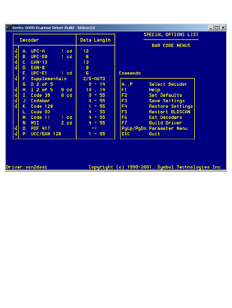
F-25
2D Scanner Drivers and Applications
Code Type Menu 1
Alpha characters are used to select code types and function keys are used to perform actions.
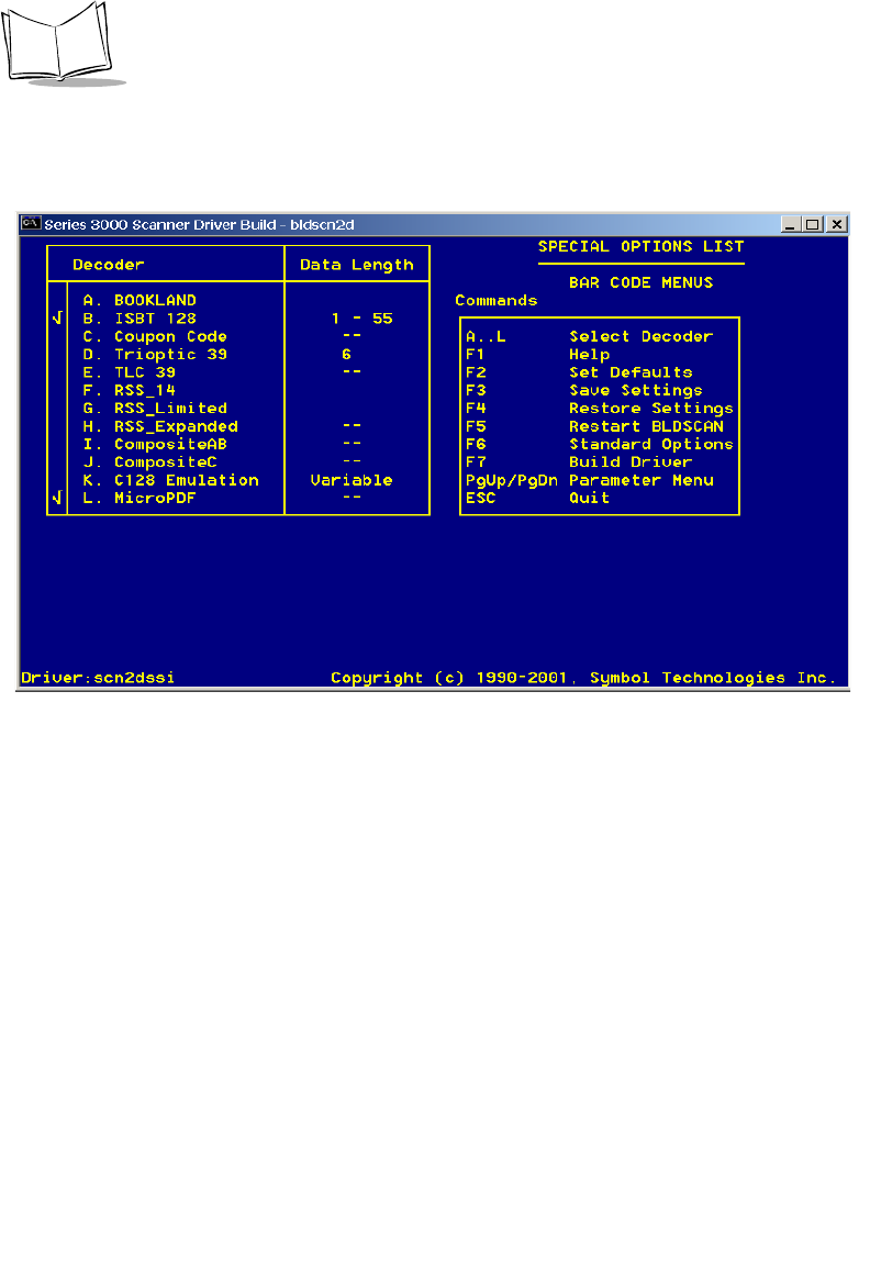
F-26
PDT 6800 Series Product Reference Guide
Code Type Menu 2
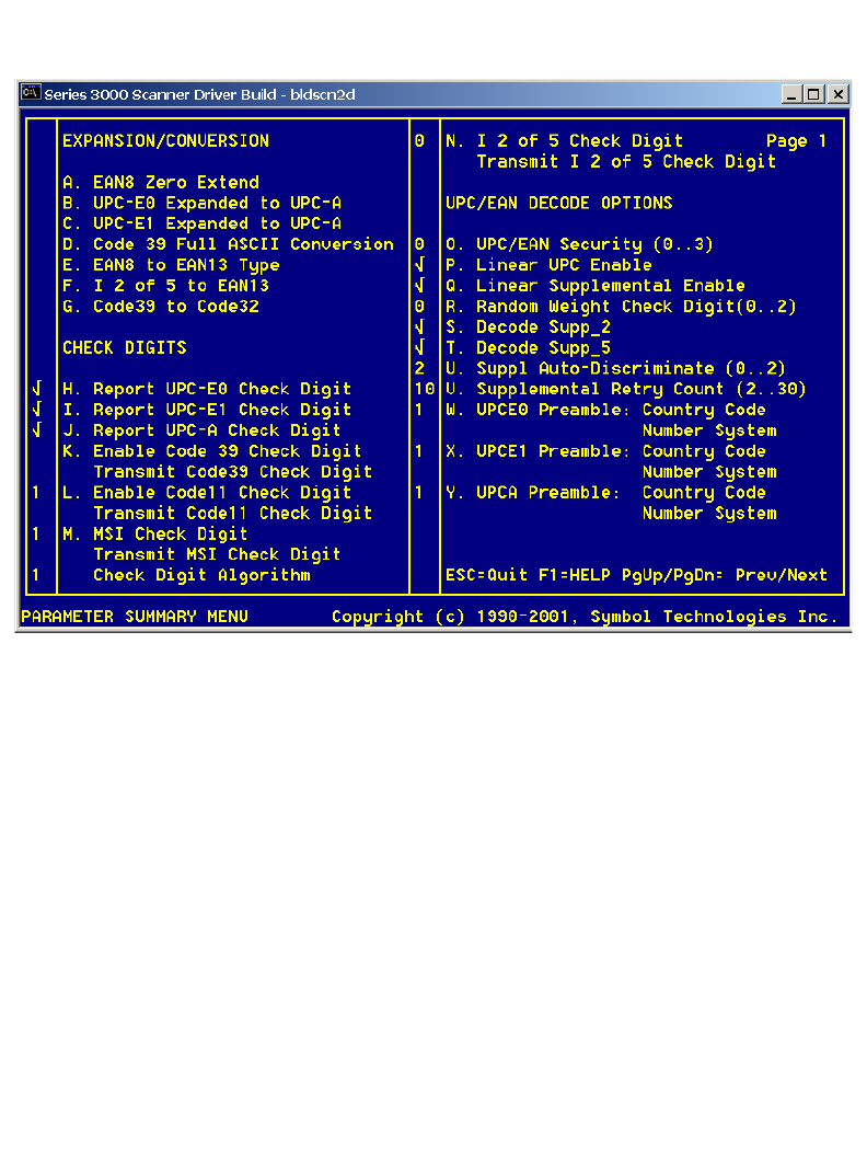
F-27
2D Scanner Drivers and Applications
Parameter Menu 1
This menu contains information for programming decoder parameters.
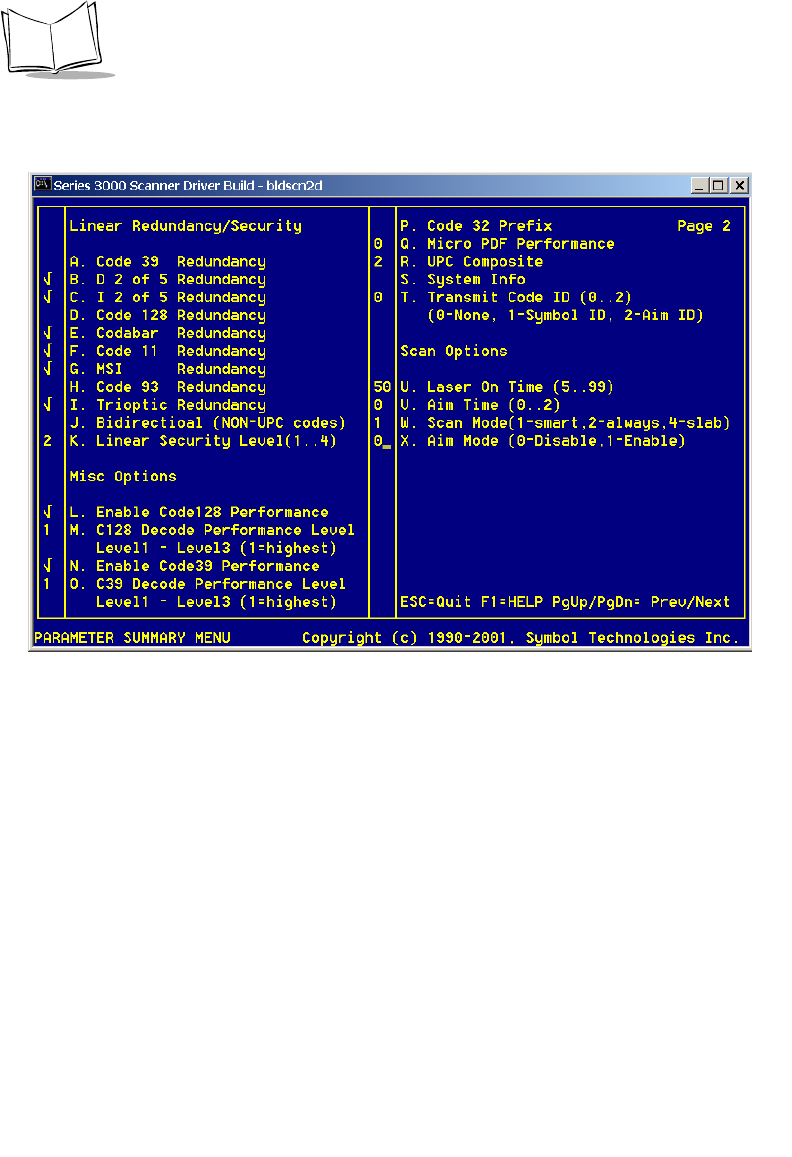
F-28
PDT 6800 Series Product Reference Guide
Parameter Menu 2

Index-1
Index
Numerics
2D scanner
driver installation . . . . . . . . . . . . . . . . . F-1
38/6860
connecting for communications . . . . . 2-14
coupling 2 or more CCMs . . . . . . . . . 2-12
daisy-chaining 2 or more . . . . . . . . . . 2-15
parts of . . . . . . . . . . . . . . . . . . . . . . . . 2-11
parts required for set up . . . . . . . . . . . . 2-2
wall mounting . . . . . . . . . . . . . 2-11, 2-12
38/6865
connecting for communications . . . . . . 2-7
connecting to power . . . . . . . . . . . . . . . 2-6
description . . . . . . . . . . . . . . . . . . 2-1, 2-2
parts of . . . . . . . . . . . . . . . . . . . . . . . . . 2-3
parts required . . . . . . . . . . . . . . . . . . . . 2-2
wall mounting . . . . . . . . . . . . . . . . . . . 2-4
38/6866
connecting for communications . . . . . . 2-7
connecting to other cradles . . . . . . . . . 2-10
connecting to power . . . . . . . . . . . . . . . 2-6
description . . . . . . . . . . . . . . . . . . 2-1, 2-2
parts of . . . . . . . . . . . . . . . . . . . . . . . . . 2-3
parts required . . . . . . . . . . . . . . . . . . . . 2-2
table mounting . . . . . . . . . . . . . . . . . . . 2-5
wall mounting . . . . . . . . . . . . . . . . . . . 2-5
6800
keyboard layouts . . . . . . . . . . . . . . . . . B-1
684X
description . . . . . . . . . . . . . . . . . . . . . . 4-1
802.11
switching to Spring RF protocol . . . . . . 5-6
A
adapter, pc . . . . . . . . . . . . . . . . . . . . . . . . 2-16
alarm . . . . . . . . . . . . . . . . . . . . . . . . . . . . . 5-2
alarm power-on . . . . . . . . . . . . . . . . . . . . . 5-2
B
back lighting . . . . . . . . . . . . . . . . . . . . . . . . 5-7
Backspace Key . . . . . . . . . . . . . . . . . . . . . 5-11
battery
charging the Lithium Ion . . . . . . . . . . . 6-7
charging the NiCd . . . . . . . . . . . . . . . . 6-6
charging tips . . . . . . . . . . . . . . . . . . . . 6-5
life . . . . . . . . . . . . . . . . . . . . . . . . . . . . 6-2
recharging spare packs . . . . . . . . . . . . 6-6
removing . . . . . . . . . . . . . . . . . . . . . . . 6-3
replacement . . . . . . . . . . . . . . . . . . . . . 6-3
battery charge LED, PC adapter . . . . . . . . 2-18
battery storage . . . . . . . . . . . . . . . . . . . . . . 6-5
BKSP . . . . . . . . . . . . . . . . . . . . . . . . . . . . 5-11
booting
cold . . . . . . . . . . . . . . . . . . . . . . . . E-1, E-2
Command Mode . . . . . . . . . . . . . . . . . 3-4
warm . . . . . . . . . . . . . . . . . . . . . . . E-1, E-2
break, key sequence for . . . . . . . . . . . . . . 5-11
C
CCM
daisy-chaining . . . . . . . . . . . . . . . . . . 2-14
mounting . . . . . . . . . . . . . . . . . . . . . . 2-11
CCM 38/6860 . . . . . . . . . . . . . . . . . . . 2-1, 2-2
connecting for communications . . . . . 2-14
coupling 2 or more together . . . . . . . 2-12
parts of . . . . . . . . . . . . . . . . . . . . . . . 2-11

Index-2
PDT 6800 Series Product Reference Guide
wall mounting . . . . . . . . . . . . . . . . . . 2-12
chapter descriptions . . . . . . . . . . . . . . . . . . . . ix
charging
Lithium Ion battery pack . . . . . . . . . . . 6-7
NiCd battery pack . . . . . . . . . . . . . . . . 6-6
spare battery packs . . . . . . . . . . . . . . . 6-6
time . . . . . . . . . . . . . . . . . . . . . . . . . . . 6-6
charging and communications module . 2-1, 2-2
cold boot . . . . . . . . . . . . . . . . . . . 5-5, E-1, E-2
Command Mode . . . . . . . . . . . . . . . . . . . . . 3-2
booting to . . . . . . . . . . . . . . . . . . . . . . 3-4
program loader . . . . . . . . . . . . . . . . . . 3-3
communications
RF network . . . . . . . . . . . . . . . . . . . . 5-16
select parameters . . . . . . . . . . . . . . . . . 3-4
status codes . . . . . . . . . . . . . . . . . .3-6, C-1
with host or printer . . . . . . . . . . . . . . 5-16
connecting for communications . . . . . . . . 2-14
38/6860 . . . . . . . . . . . . . . . . . . . . . . . 2-14
38/6865 cradle . . . . . . . . . . . . . . . . . . 2-7
38/6866 cradle . . . . . . . . . . . . . . . . . . 2-7
connecting to other cradles
38/6866 cradle . . . . . . . . . . . . . . . . . 2-10
connecting to power
38/6865 cradle . . . . . . . . . . . . . . . . . . 2-6
38/6866 cradle . . . . . . . . . . . . . . . . . . 2-6
coupling 2 or more CCMs . . . . . . . . . . . . 2-12
cradles
38/6865 . . . . . . . . . . . . . . . . . . . . . 2-1, 2-2
38/6866 . . . . . . . . . . . . . . . . . . . . . 2-1, 2-2
connecting for communications . . . . . . 2-7
connecting power . . . . . . . . . . . . . . . . 2-6
coupling 2 or more CCMs . . . . . . . . . 2-12
mounting the 38/6865 . . . . . . . . . . . . . 2-4
mounting the 38/6866 . . . . . . . . . . . . . 2-5
parts required for setting up 38/6865 . 2-2
parts required for setting up 38/6866 . 2-2
parts required for setting up
CCM 38/6860 . . . . . . . . . . . . . . . 2-2
CRD 38/6865
connecting for communications . . . . . . 2-7
connecting to power . . . . . . . . . . . . . . 2-6
parts of . . . . . . . . . . . . . . . . . . . . . . . . 2-3
wall mounting . . . . . . . . . . . . . . . . . . . 2-4
CRD 38/6866
connecting for communications . . . . . . 2-7
connecting to other cradles . . . . . . . . . 2-10
connecting to power . . . . . . . . . . . . . . . 2-6
parts of . . . . . . . . . . . . . . . . . . . . . . . . . 2-3
table mounting . . . . . . . . . . . . . . . . . . . 2-5
wall mounting . . . . . . . . . . . . . . . . . . . 2-5
D
display
key scan test . . . . . . . . . . . . . . . . . . . . . 7-8
documents available from
Symbol Technologies . . . . . . . . . . . . x
downloading
program loader . . . . . . . . . . . . . . . . . . . 3-2
using SENDHEX command . . . . . . . . . 3-2
downloading a program
cancelling . . . . . . . . . . . . . . . . . . . . . . . 3-4
ending communications . . . . . . . . . . . . 3-6
selecting communications parameters . . 3-4
starting communications . . . . . . . . . . . . 3-6
driver, 2D
installation . . . . . . . . . . . . . . . . . . . . . . F-1
E
ending self test . . . . . . . . . . . . . . . . . . . . . . . 7-8
entering data
scanner entry . . . . . . . . . . . . . . . . . . . 5-12
entering data with the scanner . . . . . . . . . . 5-12
error codes, communications . . . . . . . . . . . . C-2
error messages
double key error . . . . . . . . . . . . . . . . . . 7-2
power fault . . . . . . . . . . . . . . . . . . . . . . 7-2
replace cells . . . . . . . . . . . . . . . . . . . . . 7-2
F
flash disk
application storage . . . . . . . . . . . . . . . . 4-1
configuration file storage . . . . . . . . . . . 4-1
FLASHDSK.SYS . . . . . . . . . . . . . . . . . . . . . 4-1
FUNC Key . . . . . . . . . . . . . . . . . . . . . . . . . 5-10

Index-3
Index
I
information, service . . . . . . . . . . . . . . . . . . . . xi
K
keyboard
35-key layouts . . . . . . . . . . . . . . . . . . . B-2
46-key layouts . . . . . . . . . . . . . . . . . . . B-5
modifier keys . . . . . . . . . . . . . . . . . . . . 5-9
power on . . . . . . . . . . . . . . . . . . . . . . . 5-2
setting speed . . . . . . . . . . . . . . . . . . . . 5-10
states . . . . . . . . . . . . . . . . . . . . . . . . . 5-10
test . . . . . . . . . . . . . . . . . . . . . . . . . . . . 7-6
using . . . . . . . . . . . . . . . . . . . . . . . . . . 5-9
L
laser scanner . . . . . . . . . . . . . . . . . . . . . . . 5-12
LEDs
battery charge indicator . . . . . . . . . . . 2-16
communications . . . . . . . . . . . . . . . . . 2-17
lighting, back . . . . . . . . . . . . . . . . . . . . . . . . 5-7
loading a program . . . . . . . . . . . . . . . . . . . . 3-2
locked states . . . . . . . . . . . . . . . . . . . . . . . 5-10
low battery . . . . . . . . . . . . . . . . . . . . . . . . . 7-2
M
messages
double key error . . . . . . . . . . . . . . . . . . 7-2
low battery . . . . . . . . . . . . . . . . . . . . . . 7-2
power fault . . . . . . . . . . . . . . . . . . . . . . 7-2
replace cells . . . . . . . . . . . . . . . . . . . . . 7-2
momentary states . . . . . . . . . . . . . . . . . . . . 5-10
mounting CRD 38/6865 . . . . . . . . . . . . . . . 2-4
N
normal power on . . . . . . . . . . . . . . . . . E-1, E-2
NVM, erasing . . . . . . . . . . . . . . . . . . . . . . . 3-4
P
PC adapter
battery charge LED . . . . . . . . . . . . . . 2-16
charging time . . . . . . . . . . . . . . . . . . . 2-16
communication LED . . . . . . . . . . . . . 2-17
connecting to 6800 . . . . . . . . . . . . . . 2-17
connecting to serial device . . . . . . . . . 2-17
DB-9 connector . . . . . . . . . . . . . . . . . 2-17
parts . . . . . . . . . . . . . . . . . . . . . . . . . 2-16
power supply port . . . . . . . . . . . . . . . 2-17
set up . . . . . . . . . . . . . . . . . . . . . . . . . 2-17
PDF417
raster . . . . . . . . . . . . . . . . . . . . . . . . . 5-13
PDT 6800
keyboard layouts . . . . . . . . . . . . . . . . . B-1
PDT6842
switching 802.11 to
Spring RF protocol . . . . . . . . . . . . 5-6
PIM . . . . . . . . . . . . . . . . . . . . . . . . . . . . . 2-16
connecting for communicating
with printer . . . . . . . . . . . . . . . . 5-16
PIM, used with PC adapter . . . . . . . . . . . . 2-16
power connection
38/6865 cradle . . . . . . . . . . . . . . . . . . 2-6
38/6866 cradle . . . . . . . . . . . . . . . . . . 2-6
power fault . . . . . . . . . . . . . . . . . . . . . . . . . 7-2
Power Key . . . . . . . . . . . . . . . . . . . . . . . . 5-11
power off . . . . . . . . . . . . . . . . . . . . . . . . . . 5-3
forced . . . . . . . . . . . . . . . . . . . . . . . . . 5-3
power on . . . . . . . . . . . . . . . . . . . . . . . . . . 5-2
keyboard . . . . . . . . . . . . . . . . . . . . . . . 5-2
real-time clock . . . . . . . . . . . . . . . . . . . 5-2
remove from cradle . . . . . . . . . . . . . . . 5-2
trigger . . . . . . . . . . . . . . . . . . . . . . . . . 5-3
power, restoring after automatic shutdown 5-3
printer interface module (PIM) . . . . . . . . . 2-16
printer, communicating with . . . . . . . . . . 5-16
program loader . . . . . . . . . . . . . . . . . . . . . . 3-2
selecting . . . . . . . . . . . . . . . . . . . . . . . . 3-4
status codes . . . . . . . . . . . . . . . . . . . . . C-1
PWR Key . . . . . . . . . . . . . . . . . . . . . . . . . 5-11
R
real-time clock . . . . . . . . . . . . . . . . . . . . . . 5-2
recharging spare battery packs . . . . . . . . . . 6-6
related documentation . . . . . . . . . . . . . . . . . . x
removing the battery . . . . . . . . . . . . . . . . . . 6-3

Index-4
PDT 6800 Series Product Reference Guide
replacing the battery . . . . . . . . . . . . . . . . . . 6-3
restoring power after automatic shutdown . 5-3
S
scanning
adjusting the laser beam . . . . . . . . . . 5-12
angle . . . . . . . . . . . . . . . . . . . . . . . . . 5-14
range . . . . . . . . . . . . . . . . . . . . . . . . . 5-15
raster . . . . . . . . . . . . . . . . . . . . . . . . . 5-13
tips for successful decode . . . . . . . . . . 5-15
self test
Config Screen 1 . . . . . . . . . . . . . . . . . . 7-6
Config Screen 2 . . . . . . . . . . . . . . . . . . 7-6
ending . . . . . . . . . . . . . . . . . . . . . . . . . 7-8
Fill Screen . . . . . . . . . . . . . . . . . . . . . . 7-6
Memory Screen . . . . . . . . . . . . . . . . . . 7-6
running . . . . . . . . . . . . . . . . . . . . . . . . 7-5
Set RTC Screen . . . . . . . . . . . . . . . . . . 7-6
testing hardware components . . . . . . . 7-5
SENDHEX . . . . . . . . . . . . . . . . . . . . . . . . . 3-2
programming NVM . . . . . . . . . . . . . . . 3-2
service information . . . . . . . . . . . . . . . . . . . . . xi
setting the keyboard speed . . . . . . . . . . . . 5-10
spare battery packs, charging . . . . . . . . . . . 6-6
Spectrum24
system software . . . . . . . . . . . . . . . . . . 4-2
startup failures . . . . . . . . . . . . . . . . . . . . . . 7-3
states
locked . . . . . . . . . . . . . . . . . . . . . . . . 5-10
momentary . . . . . . . . . . . . . . . . . . . . 5-10
symbol support center . . . . . . . . . . . . . . . . . . xii
system software, Spectrum24 . . . . . . . . . . . 4-2
T
table mounting, 38/6866 . . . . . . . . . . . . . . . 2-5
temperature
battery charging . . . . . . . . . . . . . . . . . . 6-5
battery storage . . . . . . . . . . . . . . . . . . . 6-5
terminal
switching from 802.11 to Spring RF
protocol . . . . . . . . . . . . . . . . . . . . . 5-6
terminal initialization
program loader function . . . . . . . . . . . . 3-2
sendhex command . . . . . . . . . . . . . . . . 3-2
testing components, self test . . . . . . . . . . . . . 7-5
testing hardware components . . . . . . . . . . . 7-5
time required for charging . . . . . . . . . . . . . . 6-6
tips
battery charging . . . . . . . . . . . . . . . . . . 6-5
scanning . . . . . . . . . . . . . . . . . . . . . . . 5-15
troubleshooting . . . . . . . . . . . . . . . . . . . . . . 7-3
boot failure . . . . . . . . . . . . . . . . . . . . . . 7-3
startup failure . . . . . . . . . . . . . . . . . . . . 7-3
U
using the keyboard . . . . . . . . . . . . . . . . . . . . 5-9
using the scanner . . . . . . . . . . . . . . . . . . . . 5-12
W
wall mounting
38/6860 . . . . . . . . . . . . . . . . . . . . . . . 2-12
38/6860 CCM . . . . . . . . . . . . . . . . . . 2-11
38/6866 . . . . . . . . . . . . . . . . . . . . . . . . 2-5
warm boot . . . . . . . . . . . . . . . . . . . . . . E-1, E-2
warm start . . . . . . . . . . . . . . . . . . . . . . E-1, E-2

Thank you for your input—We value your comments.
Tell Us What You Think...
We’d like to know what you think about this Manual. Please take a moment
to fill out this questionnaire and fax this form to: (631) 738-3318, or mail
to:
Symbol Technologies, Inc.
One Symbol Plaza M/S B-4
Holtsville, NY 11742-1300
Attn: Technical Publications Manager
IMPORTANT: If you need product support, please call the appropriate cus-
tomer support number provided. Unfortunately, we cannot provide customer
support at the fax number above.
User’s Manual Title:________________________________________________
(please include revision level)
How familiar were you with this product before using this manual?
Did this manual meet your needs? If not, please explain._________________
_________________________________________________________________
What topics need to be added to the index, if applicable?_________________
_________________________________________________________________
What topics do you feel need to be better discussed? Please be specific.
_________________________________________________________________
What can we do to further improve our manuals?_______________________
_________________________________________________________________
_________________________________________________________________
Very familiar Slightly familiar Not at all familiar

2
70-32645-02
Revision A — August 2001
Symbol Technologies, Inc. One Symbol Plaza, Holtsville N.Y. 11742-1300
PDT 6800 Series Product Reference Guide